

Page 1

WA635SN-GN Wireless LAN Access Point
Quick Start Guide
HUAWEI TECHNOLOGIES CO., LTD.
Page 2

Copyright © Huawei Technologies Co., Ltd. 2012. All rights reserved.
No part of this document may be reproduced or transmitted in any form or by any means without prior written consent of
Huawei Technologies Co., Ltd.
Trademarks and Permissions
and other Huawei trademarks are trademarks of Huawei Technologies Co., Ltd.
All other trademarks and trade names mentioned in this document are the property of their respective holders.
Notice
The purchased products, services and features are stipulated by the contract made between Huawei and the customer. All or
part of the products, services and features described in this document may not be within the purchase scope or the usage
scope. Unless otherwise specified in the contract, all statements, information, and recommendations in this document are
provided "AS IS" without warranties, guarantees or representations of any kind, either express or implied.
The information in this document is subject to change without notice. Every effort has been made in the preparation
of this document to ensure accuracy of the contents, but all statements, information, and recommendations in this document
do not constitute the warranty of any kind, express or implied.
Huawei Technologies Co., Ltd.
Address: Administration Building,Huawei Technologies Co.,
Ltd.,Bantian,Longgang District,Shenzhen,People’s Republic of China
Postcode: 518129
Website: http://www.huawei.com
Email: [email protected]
1
Page 3
Symbol Conventions
The symbols that may be found in this document are defined as follows.
Symbol Description
CAUTION
NOTE
Indicates a potentially hazardous situation, which if not avoided, could
result in equipment damage, data loss, performance degradation, or
unexpected results.
Provides additional information to emphasize or supplement important
points of the main text.
Change History
Changes between document issues are cumulative. Therefore,the latest document issue contains all the changes in
previous issues.
Change in Issue 01 (2012-07-30)
Initial commercial release.
2
Page 4
WA635SN-GN
Quick Start Guide
Please download the detailed product documents from "http://support.huawei.com/support/".
The detailed path is as follows: Technical Support->Documentation->Wireless->Wireless WLAN->Wireless WLAN AP->Product
Documentation->WA635SN.
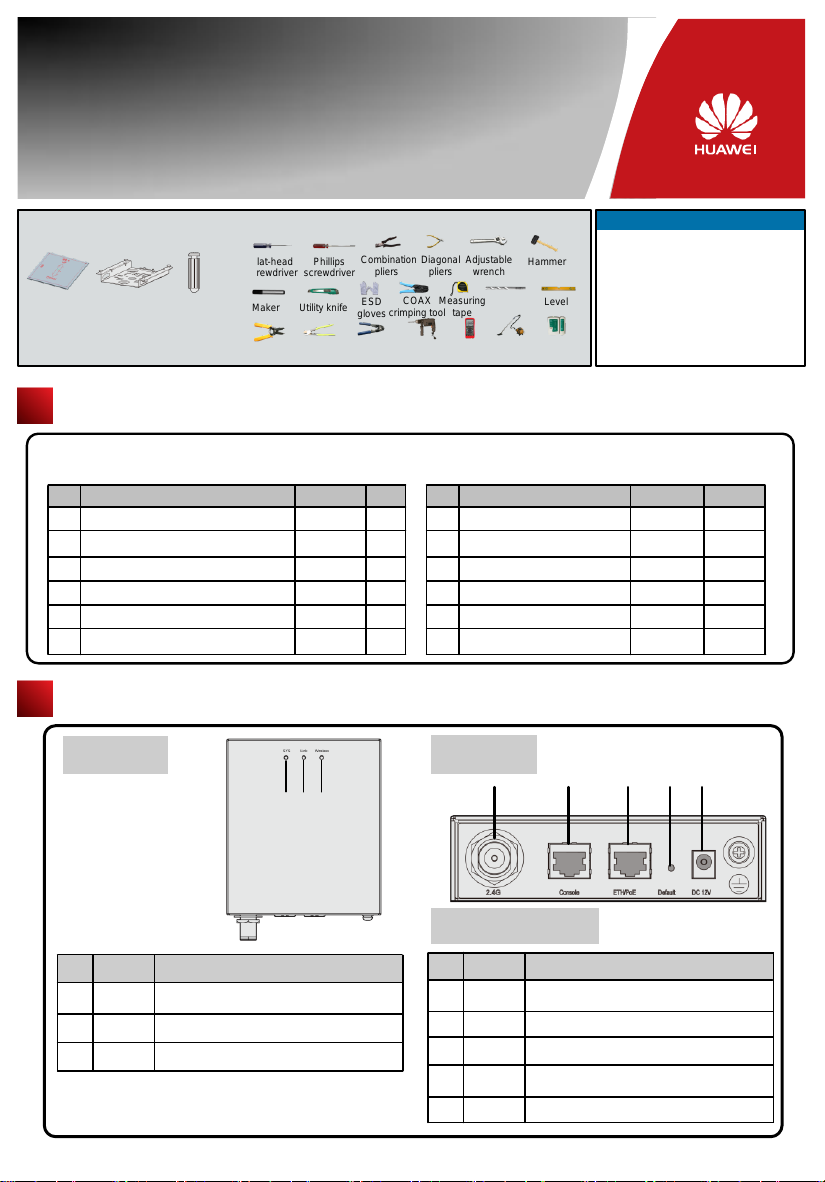
Before performing Installation, confirm that the installation accessories and tools are available.
Installation accessories:
Wall-mounting
template
Sheetmetal
wall-mounting
bracket
(Optional)
Expansion
Packing List
Unpack the equipment. Ensure that all items listed in the package list are included in the shipment. If any item is missing,
contact the supplier.
1
AP device
2
Power adapter (purchased independently)
Sheetmetal wall-mounting bracket (purchased
3
independently)
4
Expansion bolt
5
Wall-mounting template
6
Ground cable connector
Item
bolt
Installation tools:
Flat-head
screwdriver
Maker
Wire
stripper
Phillips
screwdriver
Utility knife
Cable
Crimping tool
cutter
Quantity
1
1
1
4
1
2
Combination
pliers
ESD
crimping tool
gloves
RJ45
Unit
PCS
PCS
PCS
PCS
PCS
PCS
Diagonal
Adjustable
pliers
wrench
Measuring
COAX
tape
Hammer
Multimeter
drill
Quick Start Guide (including the
7
printed packing list)
Toxic or Hazardous Substance &
8
Elements Declaration
9
Warranty card
10
Certificate of Conformance
6mm drill
bit
Vacuum
cleaner
Hammer
Level
Network
Cable tester
Item
Technical Support
Huawei Technologies Co., Ltd.
Address:Administration Building,Huawei
Technologies Co., Ltd.,Bantian,Longgang
District,Shenzhen,People’s Republic of
China
Postcode:518129
Email:[email protected]
Website:http://www.huawei.com
Quantity
Unit
PCS
1
PCS
1
PCS
1
PCS
1
Device Overview
Indicators
Name
No.
SYS status indicator,For details about indicator,
SYS
1
2
3
see the Power-on.
Link status indicator,For details about indicator,
Link
see the Power-on.
Wireless status indicator,For details about indicator,
Wireless
see the Power-on.
1 2 3
Description
3
Front view
4 5 6 7 8
Interfaces
Name
No.
2.4G
4
5
6
7
8
antenna port
Connected to an RF cable.
Console
Connected to the maintenance terminal.
Connected to a PoE power supply or switch, or
ETH/PoE
connected to the Ethernet.
Press and hold down the Reset button for 3 seconds
Default
to restore the factory settings and restart the AP.
12 V DC
Connected to the power adapter.
Description
Page 5
Installing the AP
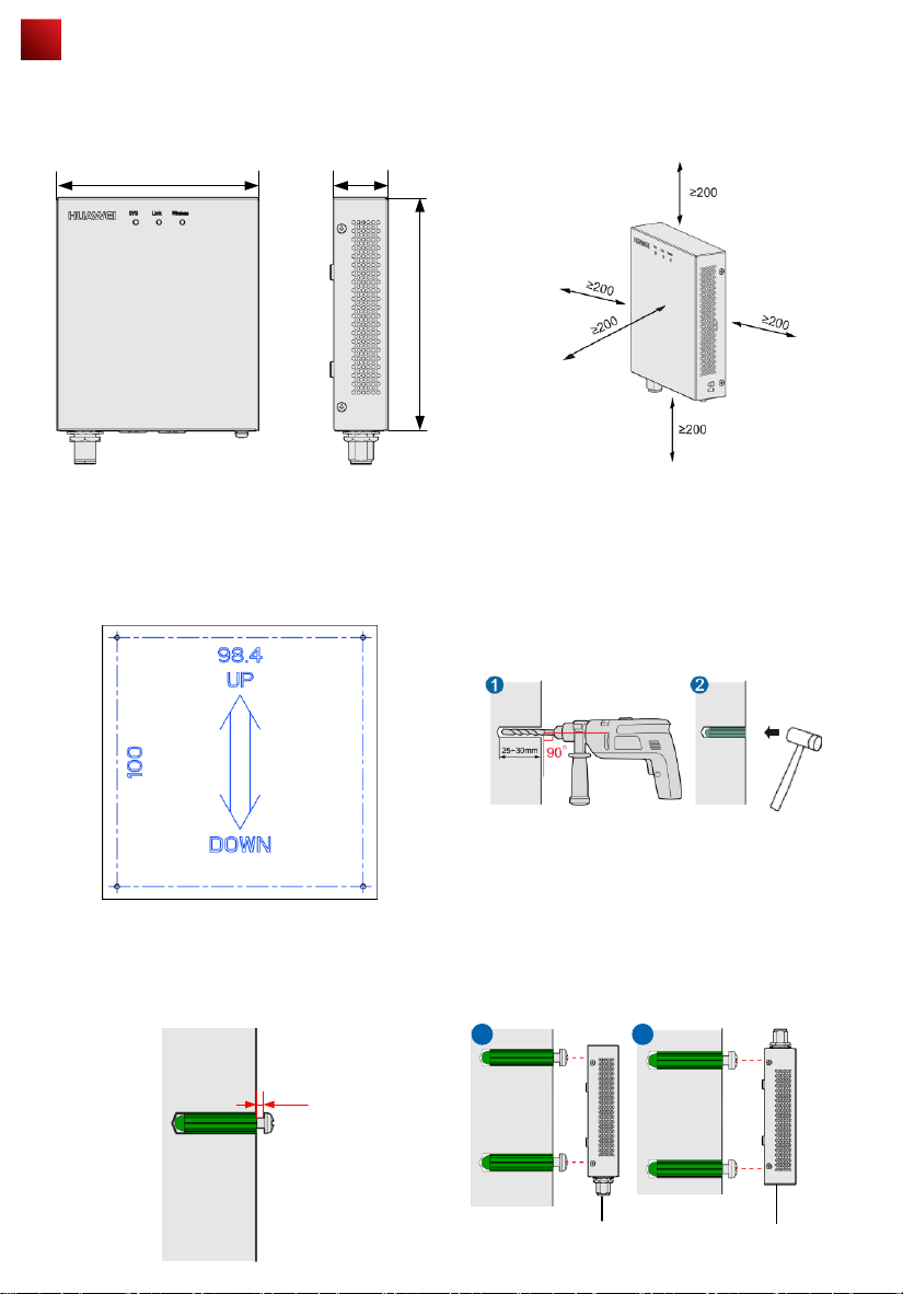
Select an appropriate installation position and leave more than 20 cm space above and around the device for cooling air
circulation.
WA635SN-GN dimensions (unit: mm) without a backplane
support
The WA635SN-GN can be installed using a wall-mounting template (for wall-mounting installation) or wall-mounting bracket
(for wall-mounting or ceiling-mounting installation).
To wall-mount the device using a wall-mounting template, perform the following operations:
130
35
Recommended WA635SN-GN installation space (unit: mm)
150
1. Use a marker to mark four installation holes on the wall.
3. Use a Phillips screwdriver to tighten four self-tapping
screws into the expansion tubes. Leave a 3 mm space
between the screw head and the wall.
3mm
2. Use #6 drill bit to drill 25-30 mm deep holes in the drilling
positions. Hammer the expansion tubes into the holes until
the expansion tubes are embedded into the wall.
4. Align the cucurbit holes at the rear side of the AP with the
screws on the wall and hang the AP on the screws. Hold
the AP with one hand and press the AP downwards with
another hand to secure the AP on the wall. The AP can be
installed with antennas upwards or downwards, which
depends on cable routing.
a b
Underfloor cabling
Overhead cabling
4
Page 6
Installing the AP
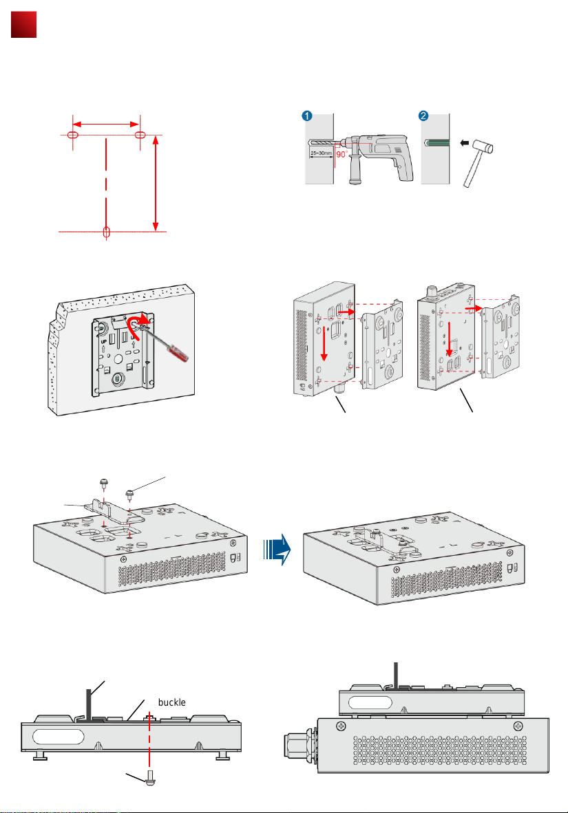
To wall-mount the device using a wall-mounting bracket, perform the following operations:
1) Attach the wall-mounting bracket to the wall, adjust
the installation position, and use the marker, level, and
measuring tape to mark the drilling positions where
expansion bolts are installed.
59mm
85mm
3) Fix the wall-mounting bracket to the wall, and use
the Phillips screwdriver to fasten three self-tapping
screws into the expansion tubes.
Field strength
场强示意
2) Use #6 drill bit to drill 25-30 mm deep holes in the drilling
positions. Hammer the expansion tubes into the holes until the
expansion tubes are embedded into the wall.
4) Align the holes at the rear side of the AP with the hooks on
the bracket and hang the AP on the bracket. Hold the AP with
one hand and press the AP downwards with another hand to
secure the AP on the bracket. The AP can be installed with
antennas upwards or downwards, which depends on cable
routing.
Install the T-rail:
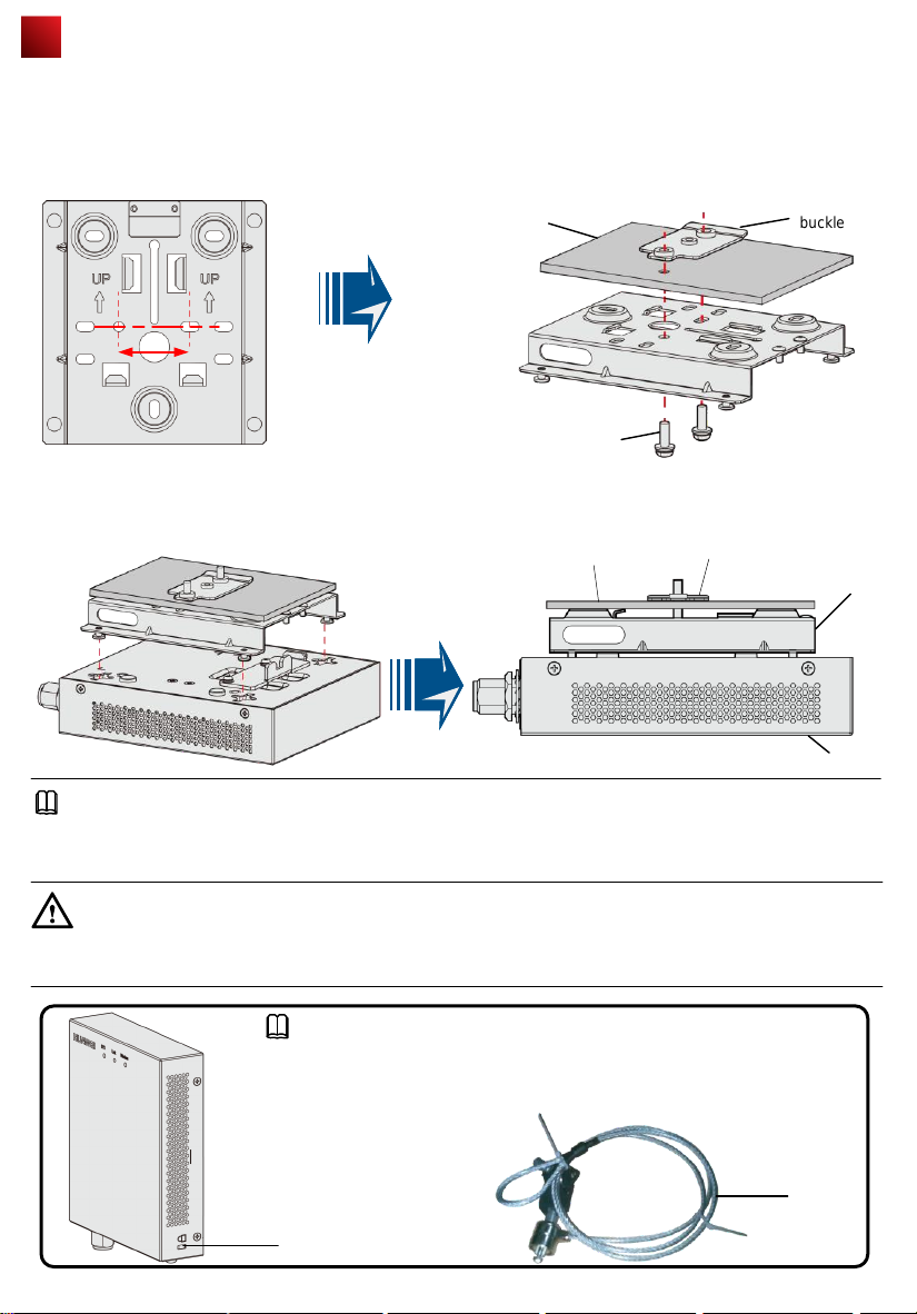
1. Fix a clip holder at the rear side of the AP with two M3*6 screws. The wall-mounting bracket is fixed at the ceiling, and
the AP is hung on the bracket. The clip holder prevents the AP from dropping.
M3*6 screw
Clip holder
2. Use screws to fix the adjustable buckle to the wallmounting bracket, hook the adjustable buckle to the T-rail,
and secure the screw on the adjustable hook to fasten the
wall-mounting bracket and T-rail.
T-rail
Adjustable
buckle
M3*6 screw
Underfloor cabling
3. Align the cucurbit holes at the rear side of the AP with
the foUr hooks on the bracket. Ensure that the AP is
installed in the correct direction; otherwise, the clip holder
cannot fix the AP.
Overhead cabling
5
Page 7
Installing the AP
Ceiling mount the AP:
1. Fix a clip holder at the rear side of the AP with two M3*6 screws. The wall-mounting bracket is fixed at the ceiling, and the
AP is hung on the bracket. The clip holder prevents the AP from dropping.
2. Remove the ceiling, determine locations of mounting holes based on the distance between two installation holes, use the
hammer drill to drill holes, and fix the wall-mounting bracket to the ceiling.
Ceiling
35mm
M4*30 screw
3. Align the cucurbit holes at the rear side of the AP with the four hooks on the bracket. Ensure that the AP is installed in the
correct direction; otherwise, the clip holder cannot fix the AP.
Adjustable
Ceiling
buckle
Adjustable
buckle
Wall-mounting
bracket
AP
NOTE
The screws provided for ceiling-mounting of APs are 30 mm long and can be used to fix an AP on a ceiling not thicker than
15 mm. To install APs on thicker ceilings, customers need to purchase longer screws.
CAUTION
Ensure that the AP is correctly installed on the wall-mounting bracket and there must be 20 cm space above and around
the AP for maintenance.
NOTE
To prevent unauthorized personnel from moving the AP, lock the AP. The preceding
figure shows the security lock. The carrier should purchase the security lock and
determine the position for installing the security lock.
Security
lock
Lock hole
6
Page 8
Connecting Cables
1
2
3
4
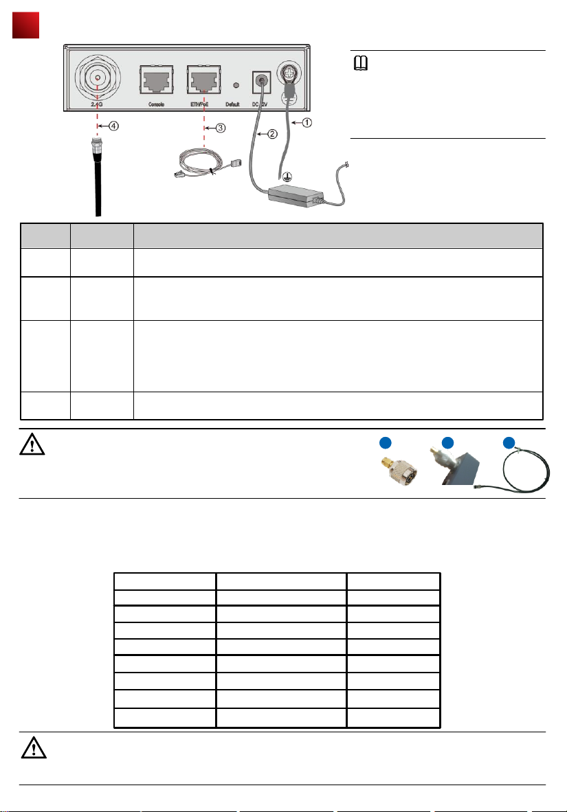
Ground cable
Power
adapter
12 V DC
Network
cable
RF cable
The M4 connector is connected to the WA635SN-GN and the M6 connector is connected to
the ground bar.
● The WA635SN-GN supports PoE power supply and DC power supply.
● Use the power adapter attached with the WA635SN-GN; otherwise, the WA635SN-GN
may be damaged.
● The network cables used are category-5 twisted pairs.
● If the AP needs to connect to the Ethernet, ensure that the Ethernet cable is working
properly. If the Ethernet cable is not working properly, for example, RJ45 connectors are
short-circuited, the AP may fail to be powered on or fail to work. Before connecting an
ethernet cable to the AP, use the cable test tool to check whether the cable is qualified. If the
cable is unqualified, replace it.
Connect AP interfaces with antennas to transmit signals, or connect the AP with a combiner
that uses the same DAS with the AP.
NOTE
1. The antennas used must comply with
local laws.
2. In North America or other regions that
Require FCC certification, use W5030H
antennas from Pulse.
DescriptionSN Name
CAUTION
When using WA635SN-GN Aps to replace WA633SNs, you need to prepare
adapters, such as SMA-to-N type adapters (figure a and b). Alternatively, make new
feeder lines matching the connectors of WA635SN-GN Aps (figure c).
Requirements for making a network cable:
● Cut the cable of proper length based on the distance between the AP and the PSE device, peel the insulation on
both ends of the network cable, and crimp the wires to RJ45 connectors.
● Connect RT45 connectors to the network cable tester to test cable connectivity. The following shows the pin
assignment.
X1 Pin
1
2
3
4
5
6
7
8
Wire Color
White and orange
Orange
White and green
Blue
White and blue
Green
White and brown
Brown
a b c
X2 Pin
1
2
3
4
5
6
7
8
CAUTION
The service network cable cannot be connected to the console port. Otherwise, the AP may be damaged when using
PoE power supply.
7
Page 9
Power-on
NOTE
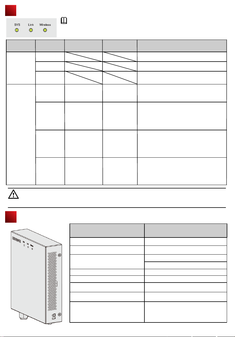
Power on the WA635SN-GN and check the indicator status to determine the System
running status.
Information
Type
Startup status
Running and
connection
CAUTION
The WA635SN-GN cannot be powered by a PoE power supply and a power adapter at the same time.
SYS WirelessLink Description
Steady green
Blinking green
Steady red
Blinking once
every 2s
Blinking once
every 2s
Blinking once
every 2s
Blinking once
every 2s
Off
Off
Steady or blinking
green
Steady or blinking
green
Off
Blinking green
Off
Blinking green
The device is being started.
The system is working properly.
The system fails to load the DRAM or System
software.
The system is working properly, but the
Ethernet is not connected and radios or all
VAPs are disabled.
The system is working properly, but the Ethernet
is not connected. The AP has wireless users
connected and is transmitting data traffic. The
indicator blinks more quickly when more data is
being transmitted.
The system is working properly, the Ethernet
is connected. Radios are disabled, and no
wireless users are connected to the AP. The
indicator blinks more quickly when more
data is being transmitted.
The system is working properly, and the
Ethernet is connected. The AP has wireless
users connected and is transmitting data traffic.
The indicator blinks more quickly when more
data is being transmitted.
Technical Specifications
Weight
Dimensions (H x W x D)
+12 V DC (Power adapter)
PoE power
Operating temperature
Relative humidity 10% to 95%
Pressure
Altitude
Item
Description
600g
35mmX150mmX130mm
Output: DC 12V ± 10%
Input: 100V~240V AC
–60 m to 4000 m,When the altitude is
between 1800 m and 4000 m, the operating
temperature decreases by 1°C each time the
altitude increases by 220 m.
-48V
-10℃ to +50℃
70kPa to 106kPa
8
Page 10
Logging In to the Router
After an AP is powered on, you can log in to the AP using the following methods.
1. Logging In to the AP Through the Console Port
This section describes how to log in to the AP through the console port. After logging in to the AP, you can configure
the AP using commands.
2. Logging In to the AP Using Telnet
This section describes how to log in to the AP using Telnet. After logging in to the AP, you can configure the AP using
commands.
1. Logging In to the AP Through the Console Port
This section describes how to log in to the AP through the console port. After logging in to the AP, you can configure the
AP using commands.
Procedure
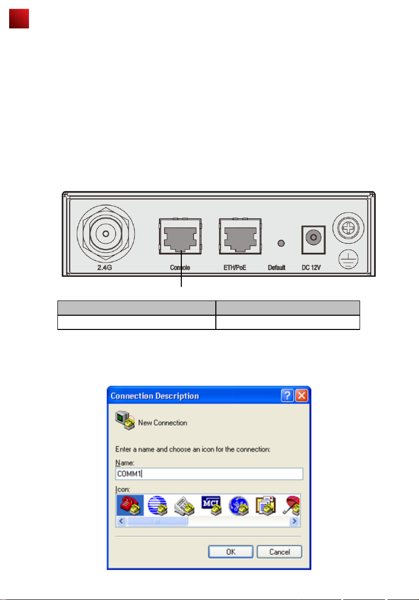
Step 1 Connect a PC to the AP with a console cable. Connect the RJ45 connector to the console port of the AP and
connect the DB9 connector to the serial port of the PC. Figure 1-1 shows the location of the AP's console port.
Figure 1-1 Location of the AP's console port
1
No Port
1
Console port
Step 2 Run the terminal emulation program on the PC. For example, to open the HyperTerminal of Windows XP on
the PC, choose Start > Programs > Accessories > Communications > HyperTerminal. Enter the name of
the new connection in the Name text box and click OK, as shown in Figure 1-2.
Figure 1-2 Setting up a connection
9
Page 11
Logging In to the Router
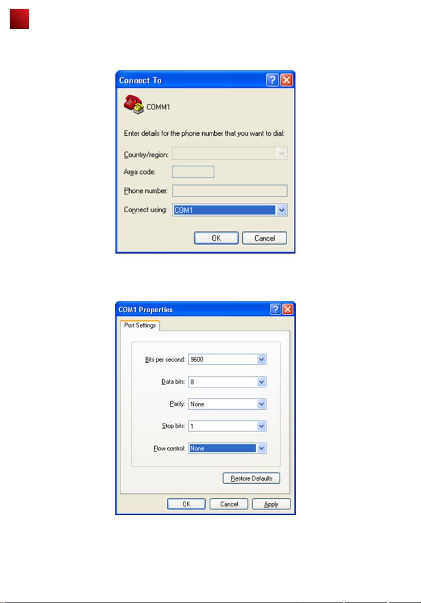
Step 3 Select the serial port used on the PC and click OK, as shown in Figure 1-3.
Figure 1-3 Selecting the connected port
Step 4 Click Restore Defaults, select 9600 bit/s from the Bits per second drop-down list box, and click OK, as shown
in Figure 1-4.
Figure 1-4 Setting communication parameters
Step 5 Press Enter on the subsequent dialog boxes until the command line prompt of the user view, such as
<Enterprise AP>, is displayed.
You can run commands to configure the AP. Enter a question mark (?) whenever you need help.
----End
10
Page 12
Logging In to the Router
2. Logging In to the AP Using Telnet
This section describes how to log in to the AP using Telnet. After logging in to the AP, you can configure the AP using
Commands.
Procedure
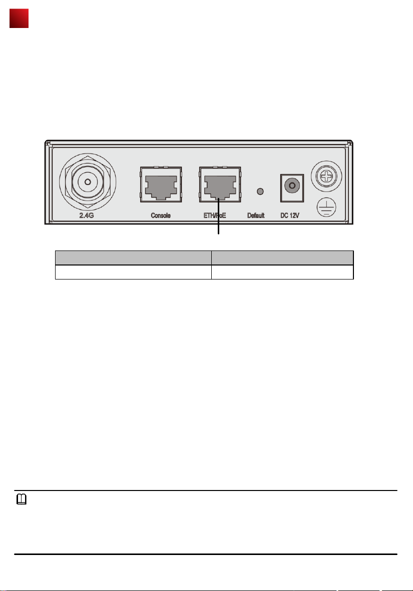
Step 1 Connect a PC to the uplink port of the AP with a network cable. Figure 1-5 shows the location of the AP's uplink
port.
Figure 1-1 Location of the AP's uplink port
1
No Port
1
Step 2 Configure a static IP address for the PC. The IP address must be on the network segment 192.168.0.1/24
(The IP address should not be same as the AP's default IP address 192.168.0.1.) and the subnet mask is
255.255.255.0.
After the configuration is complete, run the ping 192.168.0.1 command on the PC to check whether the PC
can be pinged. If the ping operation succeeds, the connection is set up successfully. If the ping operation fails,
The connection fails to be set up. Check whether the network cable works properly.
Step 3 Access the command line window on the PC. For example, if the PC runs Windows XP, choose Start > Run
And enter cmd in the displayed dialog box.
Step 4 Run the telnet 192.168.0.1 command to log in to the AP.
Step 5 Enter the default user name and password admin. If the user view is displayed, you have logged in
Successfully.
When you log in for the first time, the following page is displayed:
Username: admin
Password:
Enterprise AP:
----End
ETH/PoE
NOTE
Run the exit command to exit from the Telnet window. When the system fails to exit from the Telnet window:
● If you logged in to the AP from an AC or a switch, press Ctrl+T to return to the AC or switch view. This operation does
not affect the AP operation.
● If you logged in to the AP from a PC, directly close the Telnet window. This operation does not affect the AP operation.
11
Page 13

AP Local Configuration
WLAN services parameters of an AP are configured on the AC that is connected To the AP, and then delivered to the AP.
The following parameters are configured on the AP through Telnet or the console port.
1. Configuring the AP Access Mode
This section describes how to configure the mode in which an AP goes online.
2. Configuring VLANs on Wired Interfaces of an AP
This section describes how to configure VLANs on wired interfaces of an AP.
1. Configuring the AP Access Mode
This section describes how to configure the mode in which an AP goes online.
● AP Access Modes
After an AP starts, going online management module determines the mode in which the AP goes online. Users are
unaware of the AP access mode. In the AP startup phase, the AP obtains the its IP address, the gateway IP address,
and the AC IP address based on the access mode. After obtaining all the information, the AP sets up a Control And
Provisioning of Wireless Access Point (CAPWAP) link with the AC. The process is as follows:
1. The AP reads the configuration file and determines the mode to go online.
2. If the DHCP mode is used, the AP starts the DHCP process.
3. If the static mode is used, the AP starts the AC discovery process based on the static configuration, and
establishes a control tunnel with the discovered AC.
4. If the PPPoE mode is used, the AP initiates the PPPoE dial-up process. After obtaining the management IP
address and gateway address, the AP uses the statically configured AC IP address to discover the AC, and
establishes a control tunnel with the AC.
NOTE
By default, AP's go online in DHCP mode.
● Configuring the Mode for an AP to Go Online
● Configuring the AP to go online in DHCP mode
1. Use Telnet to log in to the AP from a PC.
login:admin
Password: //The default password is admin.
~ #
2. Configure the AP to go online in DHCP mode.
~ # cli
Enterprise AP# configure interface ethernet // Enter the AP interface view.
Enter Ethernet configuration commands, one per line.
Enterprise AP (if-ethernet) # ip mode dhcp // Set the mode in which the AP goes online.
Please reboot the AP, configuration will take effect
Enterprise AP (if-ethernet) #
3. Restart the AP to make the configuration take effect.
~ # reboot
● Configuring the AP to go online using a static IP address
1. Use Telnet to log in to the AP from a PC.
login: admin
Password: //The default password is admin.
~ #
2. Configure the AP to go online using a static IP address. The configuration items are the IP address of an AC that
is connected to the AP, the AP's IP address (mandatory), the mask address (mandatory), and the gateway
address (not required when in Layer 2 networking).
~ # cli
Enterprise AP# configure interface ethernet // Enter the AP interface view.
Enter Ethernet configuration commands, one per line.
Enterprise AP (if-ethernet) # ip mode static // Set the mode in which the AP goes online.
Enterprise AP (if-ethernet) # ac iplist 1.1.1.1 // Configure the IP address of an AC that is connected to the AP.
Enterprise AP (if-ethernet) # ip address 192.168.60.2 255.255.255.0 192.168.60.1 // Configure the IP
address of the AP.
Please reboot the AP, configuration will take effect
Enterprise AP (if-ethernet) #
3. Restart the AP to make the configuration take effect.
~ # reboot
12
Page 14

AP Local Configuration
● Configuring the AP to go online in PPPoE mode
1. Use Telnet to log in to the AP from a PC.
login: admin
Password: // The default password is admin.
~ #
2. Configure the AP to go online in PPPoE mode.
~ # cli
Enterprise AP# configure interface ethernet // Enter the AP interface view.
Enter Ethernet configuration commands, one per line.
Enterprise AP (if-ethernet) # ip mode pppoe // Set the mode in which the AP goes online.
Please reboot the AP, configuration will take effect
Enterprise AP (if-ethernet) #
3. Configure a user name and password for going online in PPPoE mode. By default, the user name and password are
both wlan@huawei and the password type is simple.
Enterprise AP (if-ethernet) # user admin password simple admin //Set the user name and password to admin.
4. Restart the AP to make the configuration take effect.
~ # reboot
NOTE
● After the configuration is complete, run the reboot command to restart the AP.
● After the configuration is complete, run the show sysinfo command to check the configuration.
Enterprise AP(if-ethernet) # show sysinfo
ap_ipmode=pppoe
ap_ipaddr=
ap_ipversion=4
ap_netmask=
ap_gateway=
ac_ip1=
ac_ip2=
ac_ip3=
ac_ip4=
pppoe_username=wlan@huawei
pppoe_pwd_type=simple
pppoe_password=wlan@huawei
2. Configuring VLANs on Wired Interfaces of an AP
This section describes how to configure VLANs on wired interfaces of an AP.
● Introduction to the Wired Interfaces
A wired interface on an AP is connected to an AC or a switch. When the AP assigns service VLANs to packets, you can
configure VLANs on wired interfaces of the AP.
● Configuring VLANs on a Wired Interface
NOTE
By default, the PVID of a wired-side interface is 0, and no VLAN is configured on the interface.
1. Use Telnet to log in to the AP from a PC.
login: admin
Password: //The default password is admin.
~ #
2. Configure VLANs and PVID on the wired interface.
~ # cli
Enterprise AP# configure interface ethernet // Enter the AP interface view.
Enter Ethernet configuration commands, one per line.
Enterprise AP (if-ethernet) # ether-port 0 [1-4095] [tag/untag] // Configure the VLANs allowed by the wired
interface.
Enterprise AP (if-ethernet) # ether-port 0 pvid [1-4095] //Configure the PVID of the wired interface.
NOTE
The configuration takes effect immediately, and you do not need to restart the AP.
13
Page 15
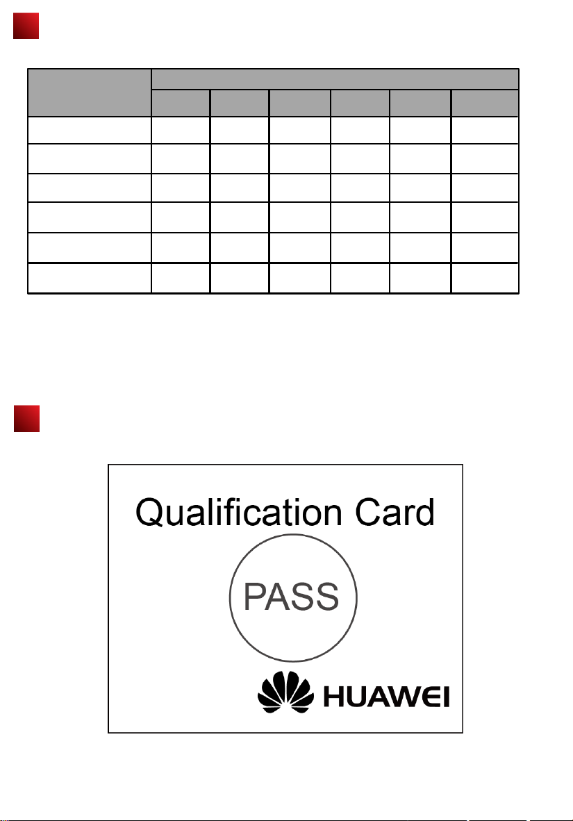
Declaration on Hazardous Substances in Electronic
Information Products
Hazardous Substances
Part
Pb Hg Cd Cr6+ PBB PBDE
Mechanical part
Board/circuit module
Signal cable
Cable connector
Power adapter
Auxiliary equipment
O:Indicates that the concentration of the hazardous substance contained in all the homogeneous materials of this
part is below the limit requirement of the SJ/T 11363-2006 standard.
X:Indicates that the Concentration of the hazardous substance contained in all the homogeneous materials of this
part is above the limit requirement.
O
O
O
O
O
O
O O O O O
O O O O O
O O O O O
O O O O O
O O O O O
O O O O O
QUALIFICATION CARD
14
Page 16
Warranty Card
Thank you for choosing HUAWEI Technologies Co., Ltd-a leading telecom solution provider. To get better services, please
read this warranty card carefully, fill in the required information and preserve this card in good condition.
Your Name
Address/Postal Code
Telephone
Product Type
Product Serial Number
Purchase Date
Invoice Number
Dealer Name
Dealer´s Address/Telephone
Preserve well. No reissue
Dealer´s Seal: Limited Warranty
Subject to the exclusions contained below, Huawei Technologies CO., Ltd. (hereinafter referred to as Huawei) warrants its
access terminals (“Products”) to be free from defects in materials and workmanship under normal consumer usage for one
year from the date of purchase of the product ("Warranty period"). During the warranty period,a Huawei authorized
service partner shall remedy defects in materials and workmanship free of charge.
Special Notice:
1. The warranty card shall be applicable only after being stamped by the dealer.
2. The warranty card must be preserved in good condition and free of any scratch or alteration.
3. To claim such service for defects that are not included in The following exclusion terms, the warranty card and the
invoice that records the product serial number shall be presented to a Huawei authorized service partner.
Exclusions:
In any of the following cases, the warranty card becomes unenforceable or inapplicable without prior notice:
1. The defects are caused by improper handling in transportation and assembly.
2. The defects are caused by the fact that the product is dismantled or altered by anyone that is not from a Huawei
authorized service partner.
3. The defects are caused by the fact that the product is used in a harsh environment that is not suitable for the operation
of the product.
4. The defects are caused by any force majeure including but not limited to fire, earthquake, lightning and tsunami.
5. The defects are caused by the fact that the product is used or handled improperly, roughly or not as instructed in the
applicable User Guide.
6. The normal wear and tear, including but not limited to the normal wear and tear of the shell and the power module, shall
not be covered by the limited warranty.
7. The warranty card is altered or illegible, or the product serial number recorded on the warranty card is inconsistent with
the actual one imprinted or labeled on the product.
In any case that is not covered by this limited warranty or should the warranty expire,Huawei shall charge for the
service(s) claimed for the products if the product is still remediable.
Huawei preserves the right for interpretation of this limited warranty.
Huawei Industrial Base, Bantian, Longgang,
Shenzhen 518129, People's Republic of China
http://www.huawei.com
Huawei Technologies Co., Ltd.
15
Page 17
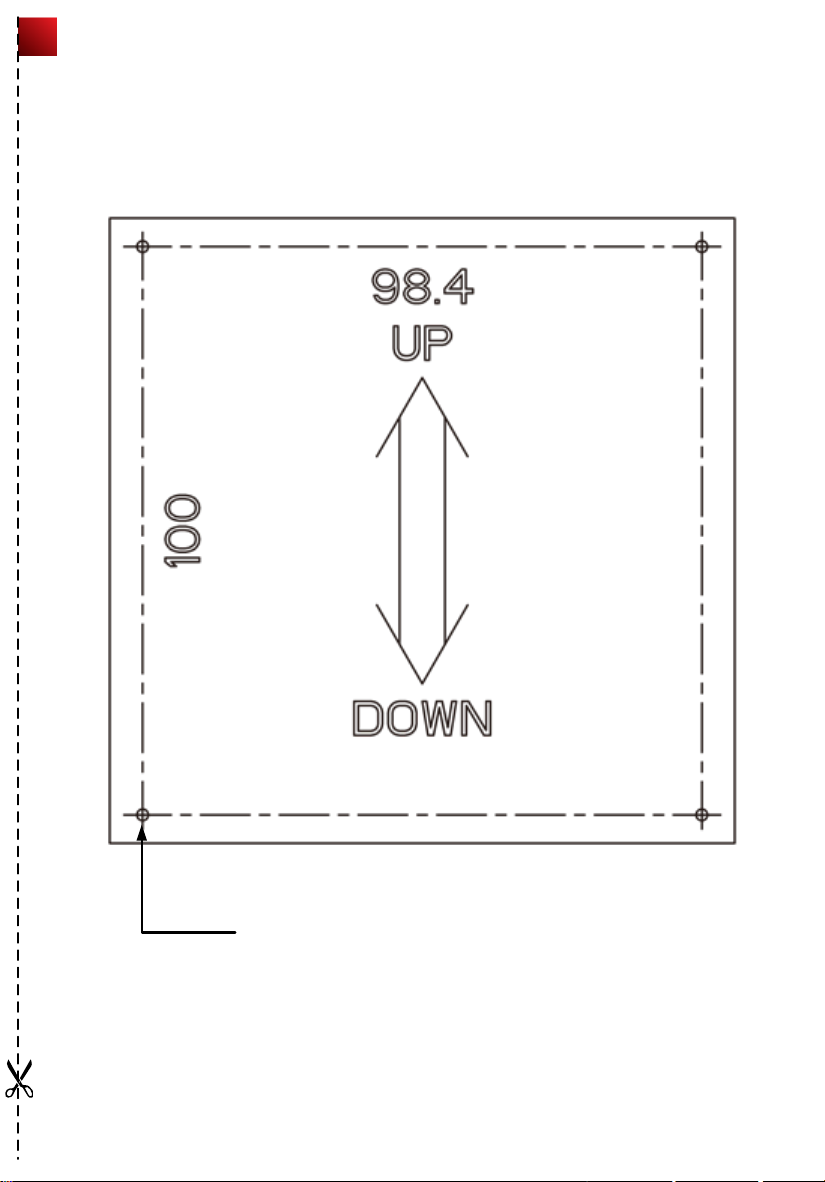
WA635SN-GN Installation Template
4-φ2
Mounting hole
16
Page 18

HUAWEI TECHNOLOGIES CO., LTD.
Huawei Industrial Base
Bantian, Longgang
Shenzhen 518129
People's Republic of China
www.huawei.com
Part Number: 31505364 Issue: 01
 Loading...