

Page 1
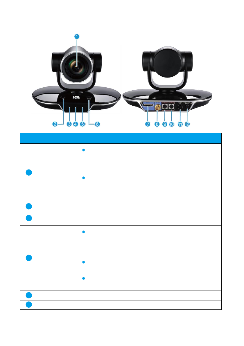
Appearance
No. Port
Description
1
Lens
VPC620
Specification 1: 12x optical zoom and 12x digital zoom
Specification 2: 4x optical zoom and 2.5x digital zoom
VPC600
Specification 1: 12x optical zoom and 12x digital zoom
Specification 2: 8x optical zoom (digital zoom not supported)
2
MODE button
Selects a parameter's mode.
3
Infrared
receiver module
Receives infrared signals.
4
Display
Displays the lens zoom information, such as C02-12X,
C02-8X, or C02-4X, when the camera starts. C02-12X,
C02-8X, and C02-4X indicate 12x, 8x, and 4x optical zoom,
respectively.
Displays settings information when the camera is working
properly.
Displays error codes if self-check or pan-tilt-zoom (PTZ)
errors occur.
5
Status indicator
Indicates running, sleep, faulty, and upgrade states.
6
SELECT button
Selects a parameter or its mode.
1
Page 2
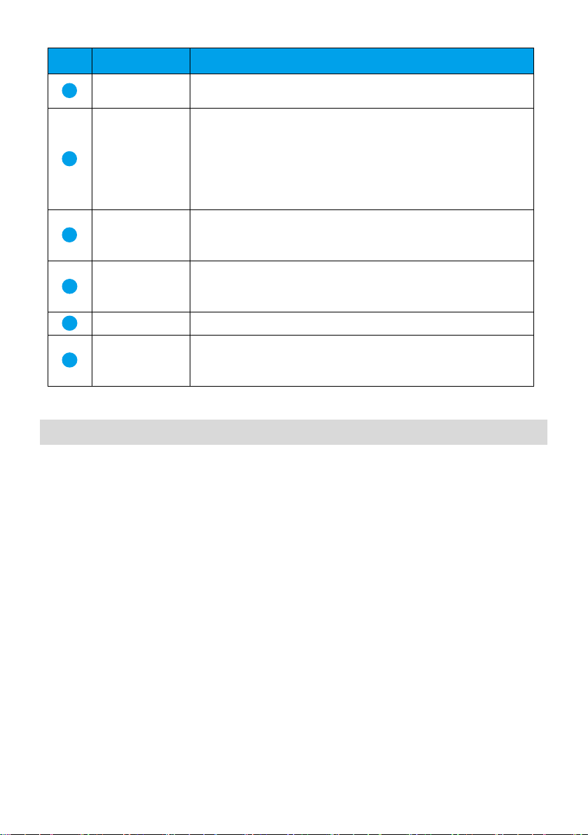
No. Port
Description
7
HD-VI port
Inputs serial control signals, infrared signals, and 12 V power.
Outputs digital visual interface (DVI) or YPbPr video signals.
8
3G-SDI port
Functions as a bayonet-neill-concelman (BNC) connector to
output 3G-SDI and HD-SDI signals.
3G = 3rd Generation
HD = high definition
SDI = serial digital interface
The VPC600 does not have this port.
9
COM OUT port
Cascades a lower-level camera. This port complies with the
Video System Control Architecture (VISCA) standard.
VISCA is a trademark of Sony Corporation.
10
COM IN port
Functions as a serial port to connect to an HD video terminal or
cascades to an upper-level camera. In addition, this port can be
used to upgrade the camera.
11
Power port
Functions as a 12 V DC power input port.
12
Power button
Powers the camera on or off.
This button is valid when the camera is connected to a power
adapter and is not used with TEX0 series video terminals.
Installation
Installing the Camera
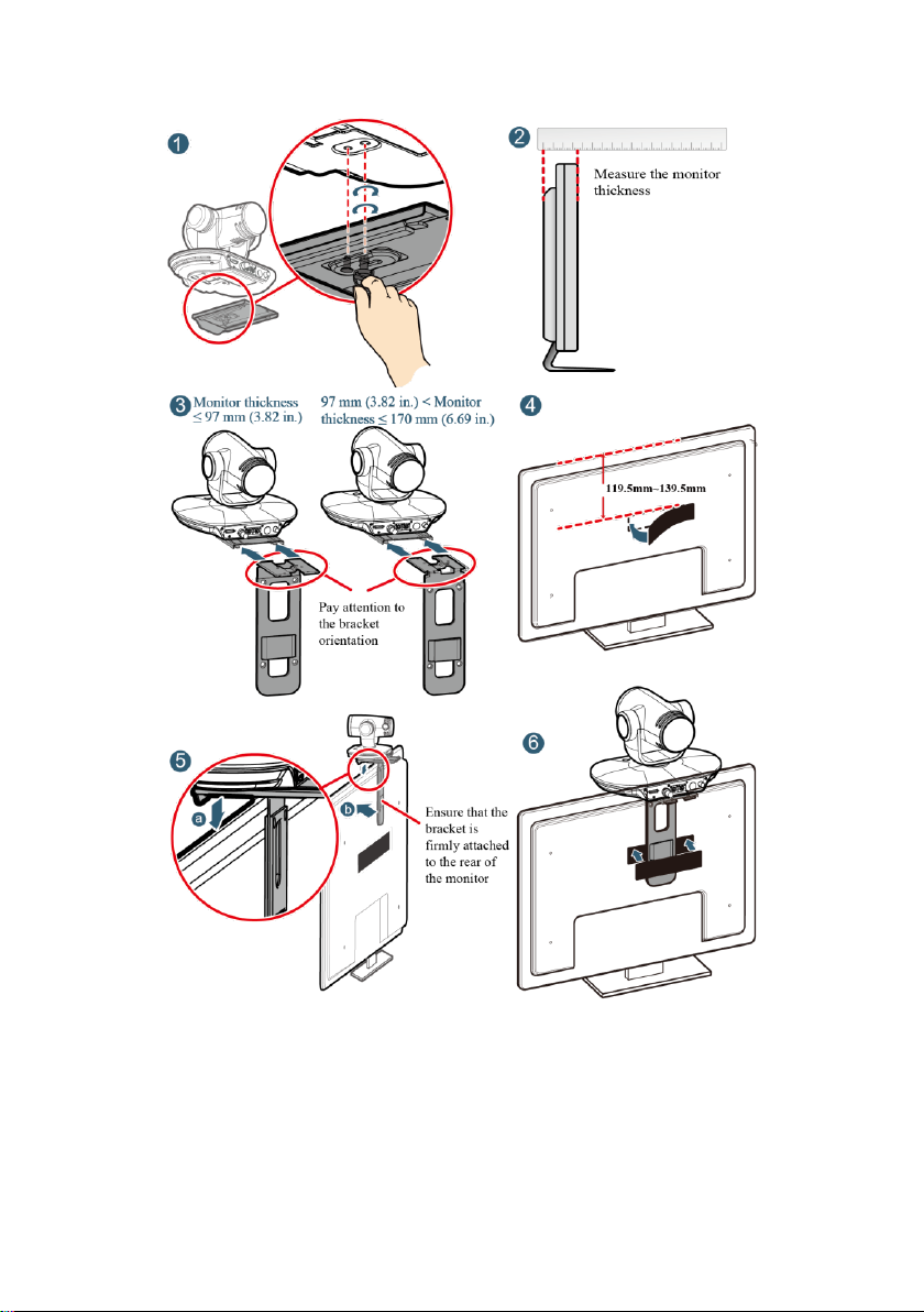
Standard
Mounting
If the monitor is 97 mm (3.82 in.) or slimmer, follow the steps in the following
figure.
If the monitor is 170 mm (6.69 in.) or thicker or is wall-mounted, use the
wall-mounting, free-standing, inverted installation, or other installation
options.
2
Page 3
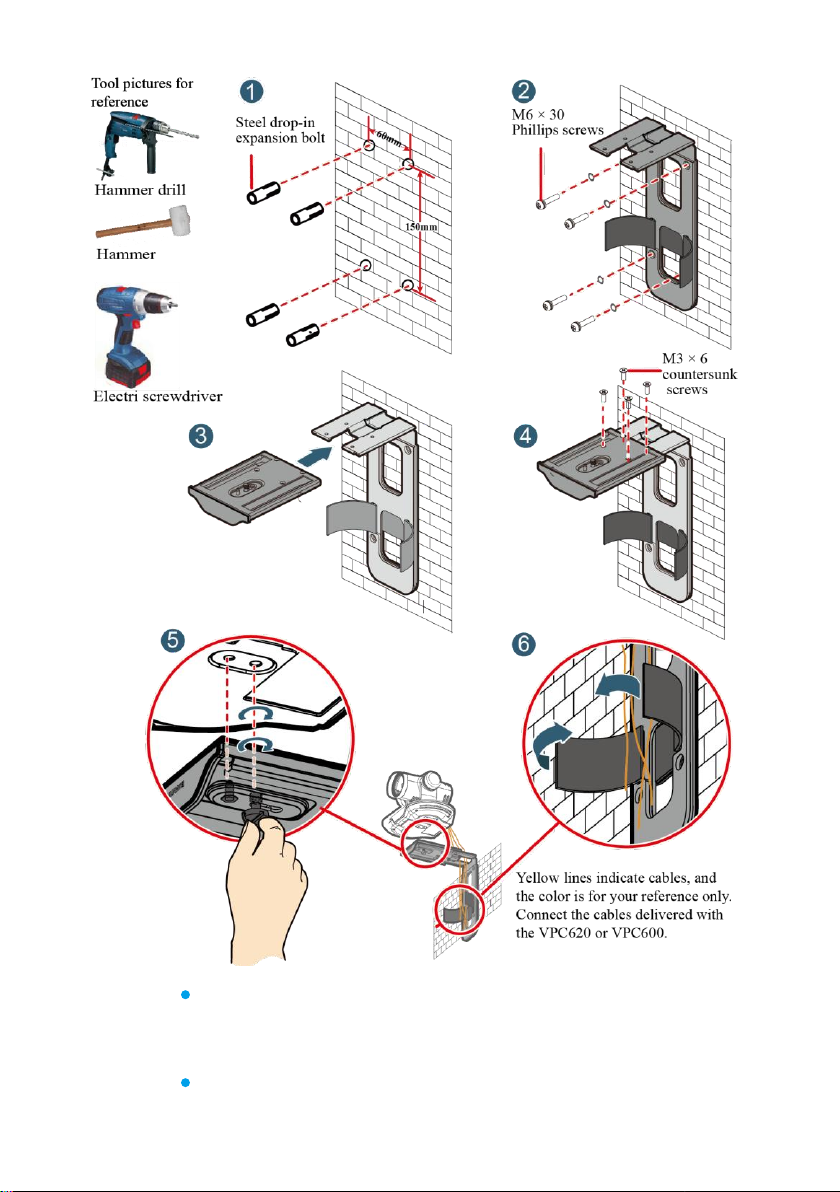
Wall-Mounting
Drill four holes in the wall for mounting the bracket, each with a diameter of 8
mm (0.31 in.) and depth of 35 mm (1.38 in.). The two holes in the upper part
must be parallel to the horizontal plane to ensure that the endpoint is
horizontally installed. Then follow the steps in the following figure to install
the VPC620 or VPC600.
3
Page 4
Normal
installation
Place the camera on a flat surface.
If you have to place the camera on a sloping surface, ensure that the slope is
less than ±15° or the camera may not function properly.
Use an optional L-shape bracket to mount the camera on a wall.
4
Page 5
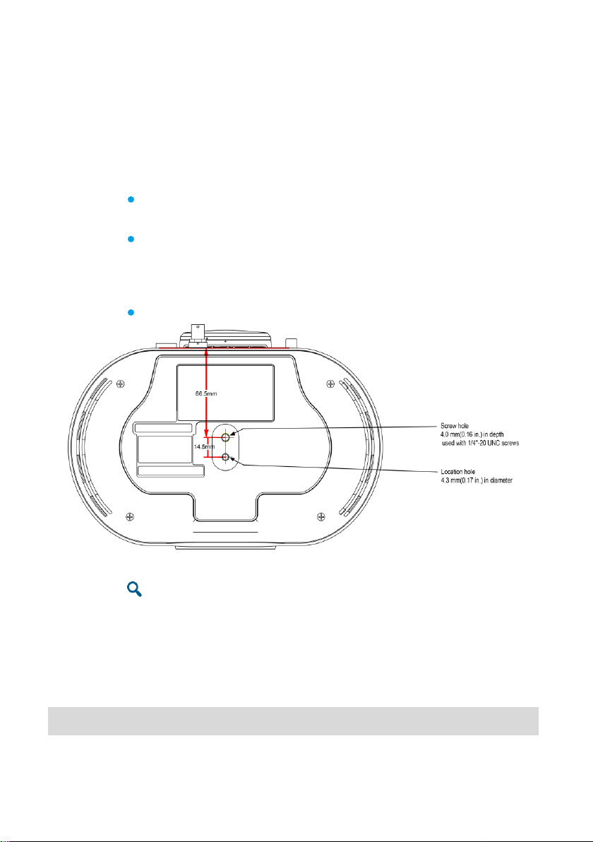
Install the camera on the bracket by fastening 1/4"-20UNC screws.
Reverse
installation
Purchase a bracket for reverse installation to mount the camera on a ceiling.
Install the camera on the bracket by fastening 1/4"-20UNC screws.
Inverted
installation
Purchase a bracket for inverted installation and mount the VPC620 or VPC600
onto the ceiling using the bracket. The bracket must meet the following
requirements:
It is able to bear a weight of at least 10.5 kg (18.74 lb) and has a thickness
between 2 mm (0.08 in.) to 3 mm (0.12 in.).
It comes with a location pillar, which can be inserted into the location hole
of the VPC620 or VPC600. The distance between the screw hole on the
bracket and location pillar must be 14.5 mm (0.57 in.), which is also the
distance between the two holes on the bottom of the VPC620 or VPC600.
It comes with a screw hole and one or more 1/4"-20UNC screws.
When attaching the purchased bracket and VPC620 or VPC600, it is recommended that you
use a 1/4"-20UNC screw delivered with the purchased bracket rather than a 1/4"-20UNC
screw delivered with the VPC620 or VPC600 because the length of the latter may be too long
or too short to hold up the purchased bracket.
Others
Install the camera on a tripod (separately purchased).
Powering the Camera On
Connect the cables and power adapter to the camera and press the power button. About 8
seconds later, video is displayed on the display device. The camera faces forward the first
5
Page 6
time you power it on. Afterward, the camera restores to the position before its power-off
each time the camera is powered on.
If the HD-VI port of the camera is connected to a TEX0 video terminal, you do not need to
connect the power adapter to the camera or press the power button. When the video terminal
is powered on, it supplies power to the camera to power the camera on.
Checking the Status Indicator
Steady green: The camera is working properly.
Steady red: The camera is in sleep mode.
Alternatively blinking red and green: The camera is upgrading.
Blinking red: The camera is faulty.
Controlling the Camera
The camera supports PTZ and lens control using an HD video terminal or remote control.
To control the camera using an HD video terminal, connect the camera to the video
terminal using a serial cable. The maximum control length (cable length) is 50 m.
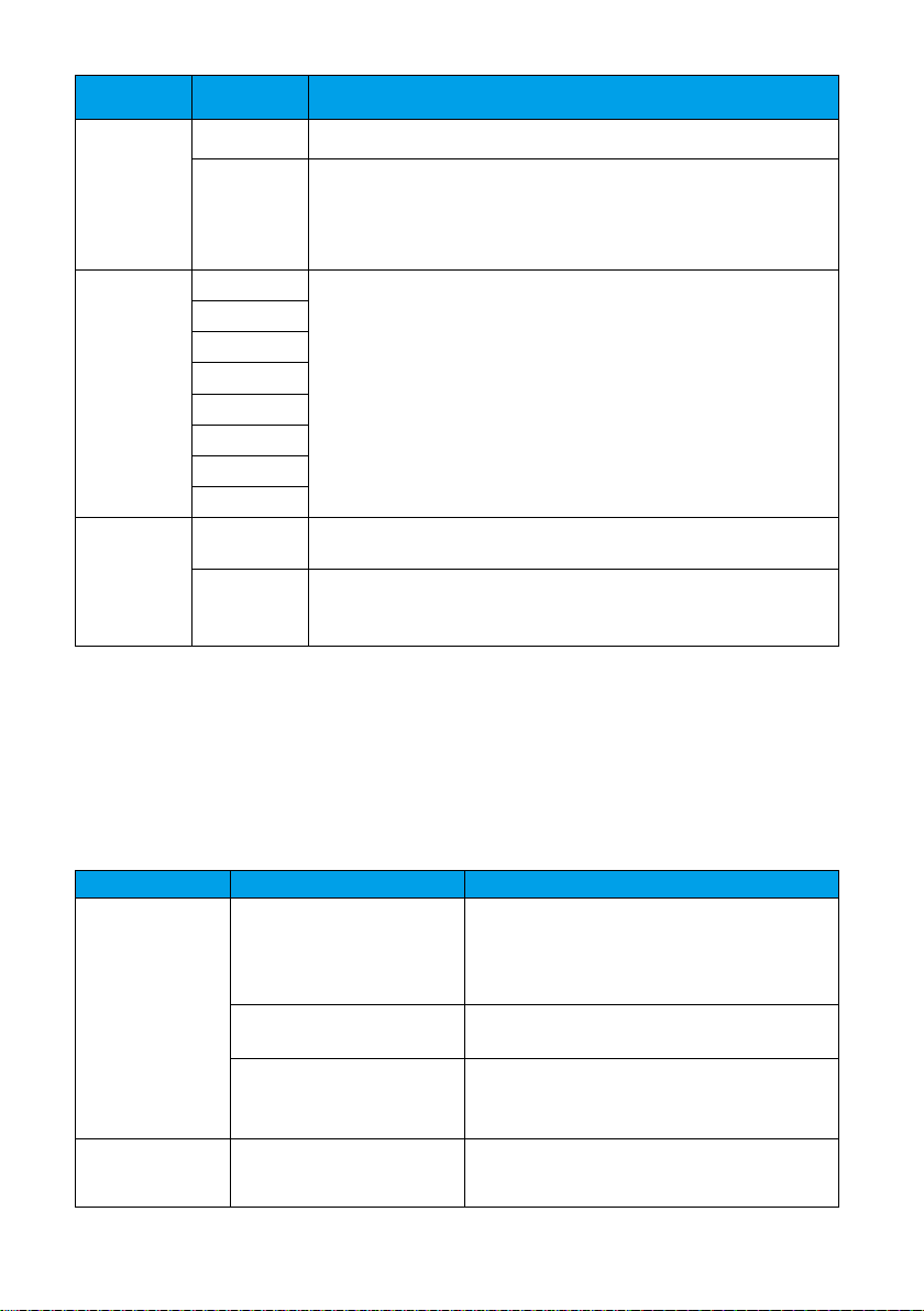
To control the camera using a remote control, set the infrared (IR) mode to LOCAL.
Parameter
Mode
Description
IR
REMOTE
The camera forwards IR signals to a video terminal and is
controlled by the video terminal. By default, IR is set to
REMOTE.
LOCAL
The camera is controlled by IR signals and stops forwarding
the signals to the video terminal.
HD-MODE
STANDARD
The video is displayed in standard mode.
If you select this option and set VEDIO to 720p 60, 1080p 30,
1080i 60, and 1080p 60, the actual video format are 720p 59.94
fps, 1080p 29.97 fps, 1080i 59.94 fps, and 1080p 59.94 fps,
respectively.
By default, HD-MODE is set to STANDARD, which is
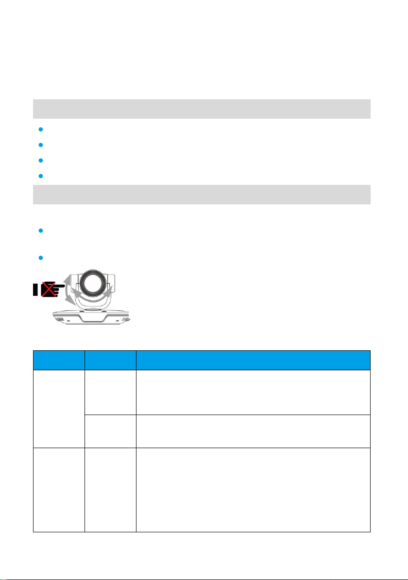
Do not manually rotate the camera or stop it from rotating when it is
powered on and working properly.
Settings
6
Page 7
Parameter
Mode
Description
recommended.
FULL
The video is displayed in full frame mode.
If you select this option, set VEDIO to 720p 60, 1080p 30,
1080i 60, or 1080p 60 based on the site requirements.
VIDEO
1080p 60
Select a video format.
Note: The VPC600 camera supports only 1080p 30, 1080p 25,
720p 60, and 720p 50 modes.
1080p 50
1080i 60
1080i 50
1080p 30
1080p 25
720p 60
720p 50
FLIP
ON
Set FLIP to ON if the camera is installed reversely.
OFF
To disable the video flip function, set FLIP to OFF (default
value).
Notes:
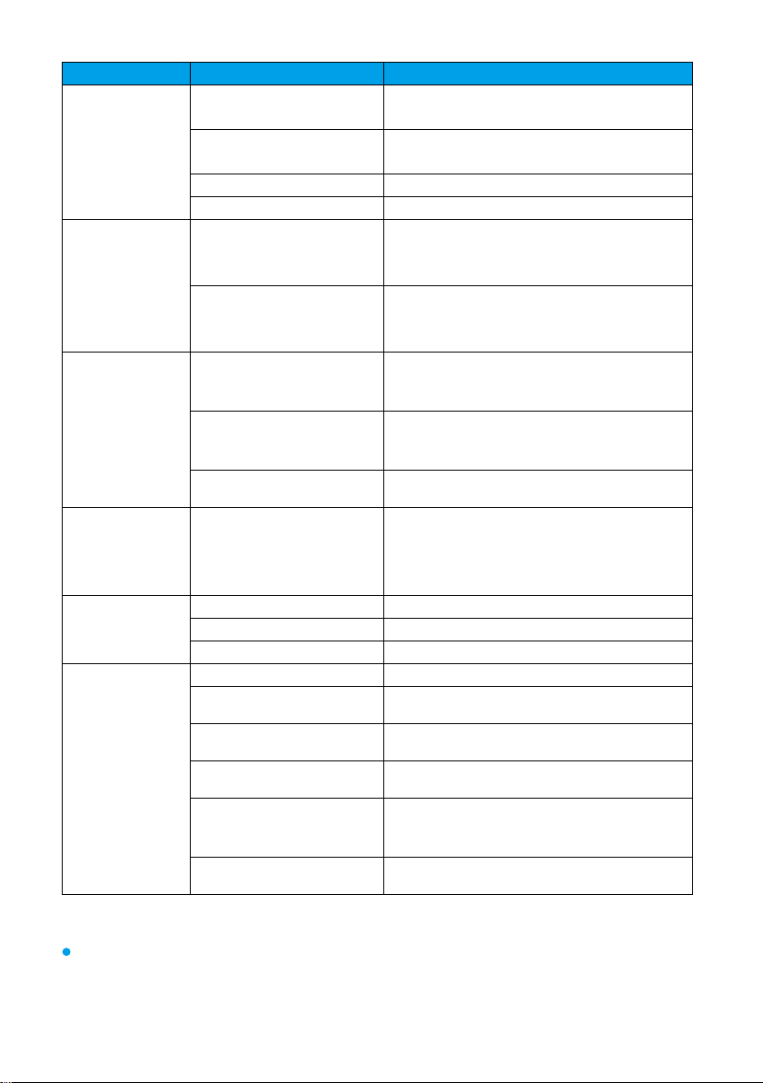
Category Item Specifications
Lens
Imaging component
2.38-megapixel and 1/2.8 type CMOS
imaging chip
CMOS = complementary
metal-oxide-semiconductor
Optical zoom
VPC620: 12x/4x
VPC600: 12x/8x
Focal length and aperture
12x: f = 3.9 mm to 46.8 mm (F1.8 to F2.8)
8x: f = 3.9 mm to 31.2 mm (F1.8 to F2.8)
4x: f = 3.9 mm to 15.6 mm (F1.8 to F2.2)
Video
Output video formats
1080p 60, 1080p 50, 1080i 60, 1080i 50,
1080p 30, 1080p 25, 720p 60, and 720p 50
1. Press the SELECT button to scroll to IR, VIDEO, or FLIP.
2. Press the MODE button to select the desired mode. The mode changes each time you press MODE.
3. Press the SELECT button to confirm your selection.
If the text blinks, the settings do not take effect. In this case, press the SET button for the settings to take effect.
Specifications
7
Page 8
Category Item Specifications
Horizontal angle of view
6.3° (TELE end) to 72° (WIDE end), with a
wide-angle lens installed
Lowest operating
luminance
2 lux (F1.8, 50 IRE)
IRE = Institute of Radio Engineers
Shutter speed
1/25 seconds to 1/10000 seconds
Local camera presets
30
PTZ capability
Horizontal
Range: ±100°
Speed: 2°/s to 100°/s
Relocation precision: ±0.1°
Vertical
Range: ±30°
Speed: 2°/s to 25°/s
Relocation precision: ±0.1°
Automatic
adjustment
Automatic white balance
(AWB)
Automatic, manual, and one-push
Automatic exposure (AE)
Automatic, manual, Iris priority, and shutter
priority
Automatic focus (AF)
Automatic and manual
Infrared remote
control
Infrared signal reception
Comply with the following standards:
Control distance: 6 m
Vertical angle: ±15°
Horizontal angle: ±30°
Power and
power supply
Input voltage
100–240 V AC, 50 Hz or 60 Hz
Output voltage
12 V DC
Power
< 22.4 W
Physical
specifications
Control port rate
9600 baud
Ambient temperature
0°C to 40°C
Operating humidity
0% to 90%
Operating height
≤ 5000 m (16.4 ft)
Dimensions (H x W x D)
157 mm × 234 mm × 163 mm (6.18 in. x
9.21 in. x 6.42 in.)
Weight (unpacked)
< 1.7 kg
Safety Precautions
Before you use the product, refer to the product vendor for version mapping information and to confirm
compatibility with other videoconferencing equipment.
8
Page 9
Keep the device dry and prevent it from colliding with other objects during storage, transportation, and
Question
Why can't I use PTZ to control the camera from an HD video terminal?
Answer
1. Th serial connection between the camera and the HD video terminal is
incorrect.
2. The serial port of the HD video terminal or the camera type is set incorrectly.
Question
Why does the camera fail its startup diagnosis along with one of the following
symptoms: 1) The camera fails to start. 2) The PTZ generates abnormal noise. 3)
Nothing is displayed on the camera screen?
Answer
A nonstandard power adapter may be used. The standard one provides a 12 V
DC output.
The connector at the low-voltage side of the camera's power adapter has been
reconstructed, or the cable of this power connector has been extended. If the
cable of the camera adapter is not long enough, extend the cable of the power
socket.
Question
Why is the camera video not displayed on the display connected to the HD video
terminal?
operations.
During installation and commissioning, ensure that the camera is properly grounded, and do not insert or
remove the camera video cables when the camera is powered on.
Do not use any power adapter other than the one provided with the device. In addition, do not refit the
adapter.
Do not attempt to dismantle the device. In case of any faults, contact an authorized maintenance center.
Position the device on stable surfaces only.
Keep the device or its accessories away from children. Swallowing the accessories may be fatal.
Keep the power plug clean and dry to prevent electric shocks or other hazards.
Before cleaning the device, shut it down and disconnect the power supply.
Do not press, scratch, or hit the lens and display with force.
Do not touch the lens or display with any rubber or plastic items as doing so may impair brightness.
Dispose packaging, batteries, and the devices according to the local regulations. Please recycle if possible.
To know more precautions, contact your device provider.
This is a class A product. In a domestic environment, this product may cause radio interference in which case
the user may be required to take preventative measures.
Troubleshooting
9
Page 10
Answer
1. The HD video terminal and camera are not connected correctly.
2. The input and output settings on the HD video terminal are incorrect.
3. The HD video terminal does not support the camera's video format.
4. The display does not support the video output format set on the HD video
terminal.
Question
Why does the display fail to display any video after the camera has worked for a
period?
Answer
Check the camera's working environment. For example, check whether the
cables are connected securely, whether the voltage is stable, and whether heat is
dissipated properly.
Question
Why is the camera video displayed unclearly or why cannot the camera
automatically adjust its focus after the camera is powered on?
Answer
The lens surface is not clean, with dust, fingerprint, or mist on it.
The camera is not in autofocus mode.
To set the camera to autofocus mode, perform the following operations:
Press on the remote control to access the camera control page. On the
remote control interface, select Adjust Focus, use the direction keys to select
on the remote control to set the camera to autofocus mode.
The distance between the object and the camera is less than 0.7 meters, or the
camera shooting angle is improperly set.
Question
Do the cameras support daisy chain cascade control? If daisy chain cascade
control is supported, how are the cameras connected and controlled? How are the
camera address codes set? Why cannot the cameras be controlled after they are
connected?
Answer
The Huawei VPC620 and VPC600 cameras support the Video System Control
Architecture (VISCA) protocol and cascade control.
Connection method: Use a keyboard that supports the VISCA protocol to
connect the cameras. Connect the COM IN port of the first camera to the VISCA
keyboard. Then, connect the COM OUT port of the first camera to the COM IN
port of the second camera, the COM OUT port of the second camera to the COM
IN port of the third camera, and so on. A maximum of seven cameras can be
connected in this serial connection mode.
The VISCA protocol supports cascade control of a maximum of seven cameras.
The address codes are automatically negotiated and increase by 1 from the first
10
Page 11
camera to the seventh camera.
If the control is abnormal, check the cables and their connections. Ensure that the
cables and their connections are normal. Ensure that the keyboard can properly
control the first camera. If the first camera can be properly controlled but the
other ones cannot, check the cable length. Ensure that the cable length does not
exceed 50 meters. If the fault persists, restart the keyboard and the cameras.
11
 Loading...