

Page 1
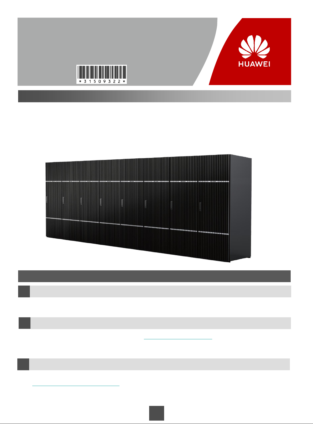
OceanStor 18000F V5 Series
V500R007
Quick Installation Guide
Issue: 09
Date: 2019-12-30
Introduction to OceanStor 18000F V5 Series
As Huawei's next-generation storage systems dedicated to large- and medium-scale data centers in the big data
era, the OceanStor 18500F V5/18800F V5 storage system fully meets the most demanding requirements for mass
data storage, data access, data availability, storage utilization, energy conservation, and ease of use.
The product models applicable to this document:
OceanStor 18000F V5 series: OceanStor 18500F V5/18800F V5
Before You Start
Overview
a
This guide describes how to quickly install OceanStor 18500F V5/18800F V5. For details, see the OceanStor
18000 and 18000F V5 Series V500R007 Installation Guide.
How to obtain help
b
You can obtain the product documentation from https://enterprise.huawei.com. You can also register for a
Huawei support account at this website to browse and download valuable information and sign up for product
updates.
Feedback
c
Your feedback is important to us. If you have any comments about this document, go to
https://support.huawei.com/enterprise (Huawei enterprise technical support website) to submit your
feedback and suggestions.
Copyright ©Huawei Technologies Co., Ltd. 2019
1
All rights reserved.
Page 2
Safety Information
Do not operate devices or handle cables on a stormy day.
To avoid eye injuries, do not look into the optical outlets without eye protection.
To avoid electric shock, do not wear an ESD wrist strap during the power-on process.
CAUTION
Before you handle devices, wear ESD clothes, wear a pair of ESD gloves or an ESD wrist strap, and remove
conductive objects such as ornaments and watches.
NOTICE
To prevent data loss, do not remove or insert controllers, disks, expansion modules, or cables during the
power-on process.
To prevent damage to a storage system, make sure each storage system is properly grounded before
powering it on.
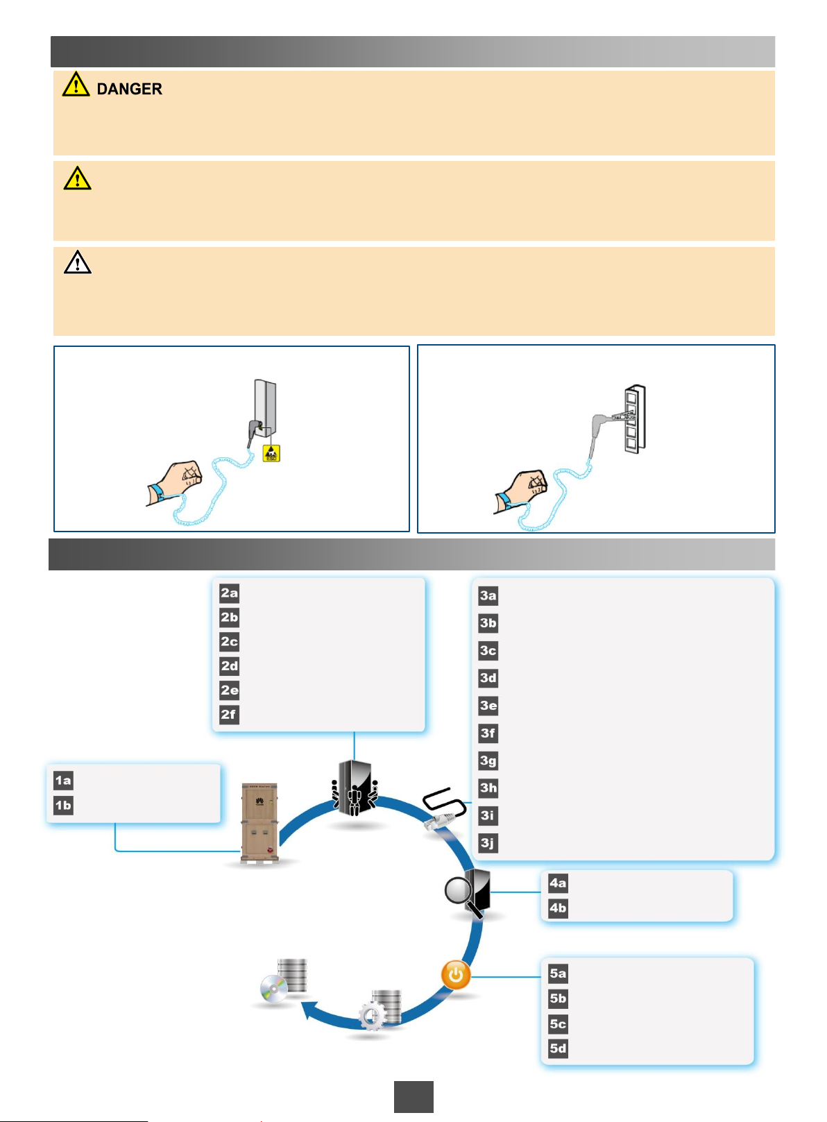
Scenario 1 Wearing an ESD wrist strap whose
ground terminal is a plug
Installation Process
Planning positions of bays
Planning positions of holes (for
underfloor cabling only)
(Optional) Removing side panels
Securing bays
(Optional) Connecting bays
(Optional) Removing the KVM
panel
Checking installation tools
Checking devices and
components
Preparing for the Installation
(Optional) Installing Host Software
Installing Bays
Scenario 2 Wearing an ESD wrist strap whose
ground terminal is a metal clip
Routing cables between bays
Connecting cables on the service processor
(SVP) and a controller enclosure
Connecting the SVP to controller enclosures or
controller enclosures to management networks
using network cables (for multiple system bays)
Connecting data switches to controller enclosures
using AOCs (for multiple system bays)
Connecting SAS cables (for a storage system
with both system bays and disk bays)
Connecting controller enclosures to application
servers
(Optional) Connecting the SVP to a maintenance
terminal
Connecting the controller enclosure to a
maintenance terminal
Connecting ground cables
Connecting
Assembling PDU connectors
Cables
Inspecting
Hardware Installation
Checking device installation
Checking cable connections
Powering On the
Storage System
Initializing the Storage System
2
Power-on procedure
Pressing the power button on
the controller enclosure
(Optional) Powering on the KVM
Verifying that the storage
system is powered on
Page 3
1 Preparing for the Installation
Checking installation tools
1a
Ensure that the following installation tools are ready:
Phillips screwdrivers (M3 to M6)
Diagonal pliers
Adjustable wrenches
1b Checking devices and components
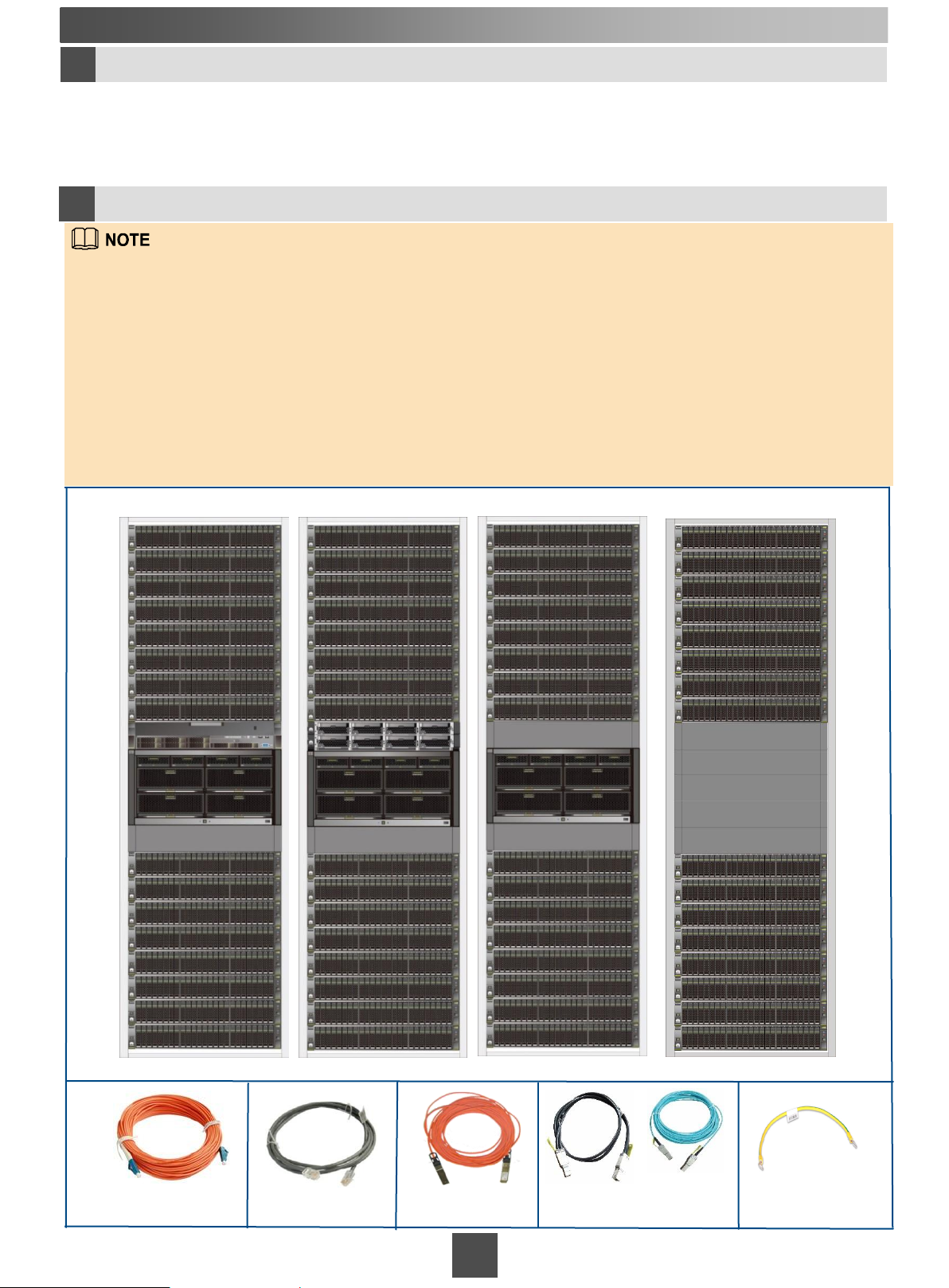
The delivered components vary depending on the disk configuration and number of system bays you have
purchased. For details about all required components and materials, see the Packing List.
Storage devices are debugged before delivery. If multiple sets of storage devices are delivered, ensure that
each set is installed in the correct system and that devices are not mixed up.
After arrival, devices are identified by the packing list No. (P/L No.) shown on the external carton. The P/L
No. is the same for devices in the same set. The packing list count (Site Count) indicates the number and ID
of the devices.
Before unpacking goods, identify different sets of storage devices and store them separately to prevent
device mix-up from causing a system failure. For details, see the OceanStor 18000 and 18000F V5 Series
V500R007 Installation Guide.
OceanStor 18500 V5 V500R007 supports DC power modules.
This document uses OceanStor 18500F V5 V500R007 as an example. The installation procedure of the
OceanStor 18800F V5 V500R007 is similar.
Check the integrity of the following devices and components.
System bay 0 System bay 1 System bay 2&3 Disk bay
Multimode optical
fiber
Network cable
Active optical cable
(AOC)
mini SAS HD
electric cable
mini SAS HD
optical cable
3
Ground cable
Page 4
2 Installing Bays
Planning positions of bays
2a
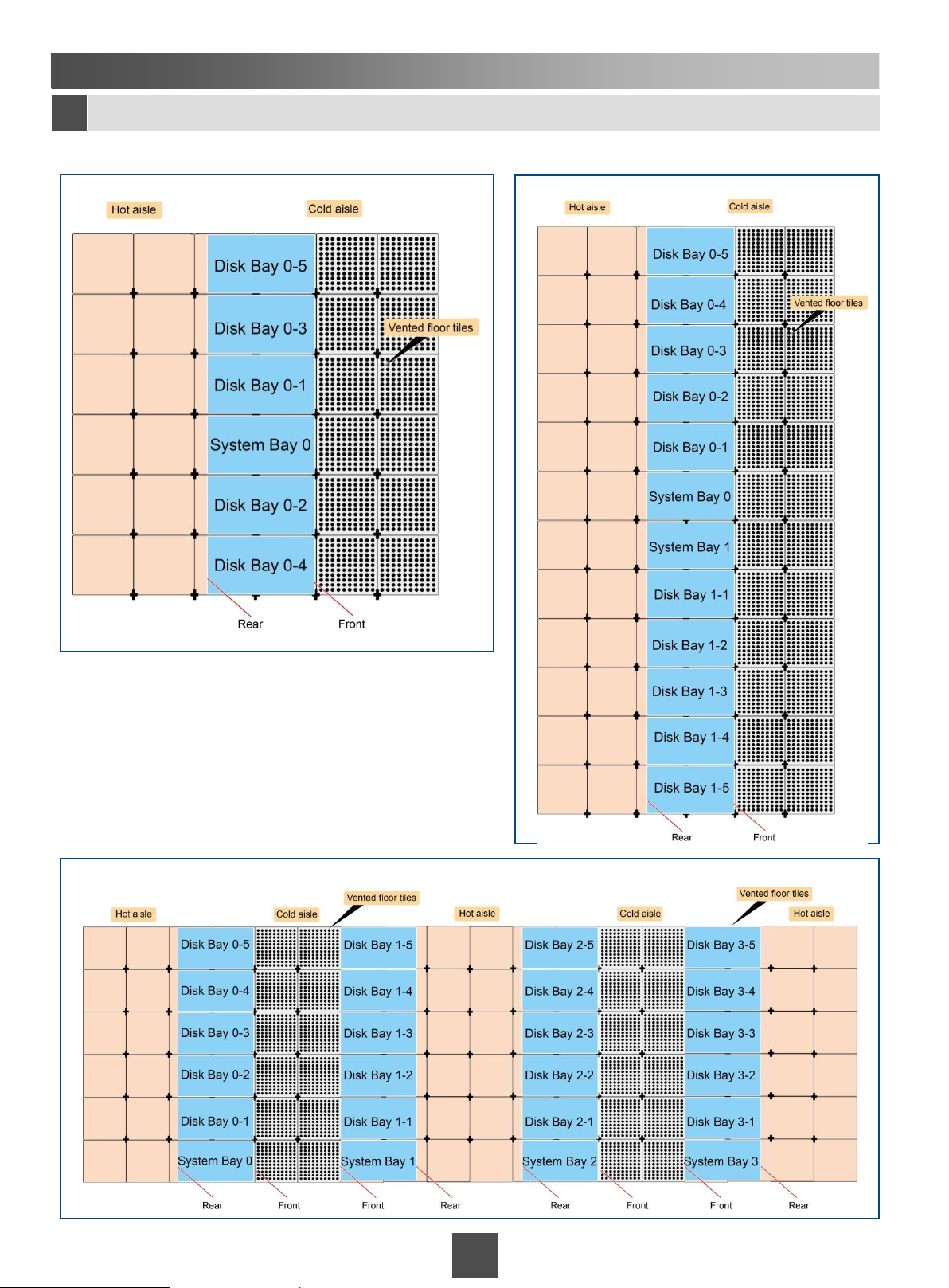
Standard bay layout
To facilitate cabling, you are advised to use the following standard layouts.
Scenario 1 Standard layout of 4 controllers
Scenario 2 Standard layout of 8 controllers
Scenario 3 Standard layout of 16 controllers
4
Page 5
Non-standard bay layout
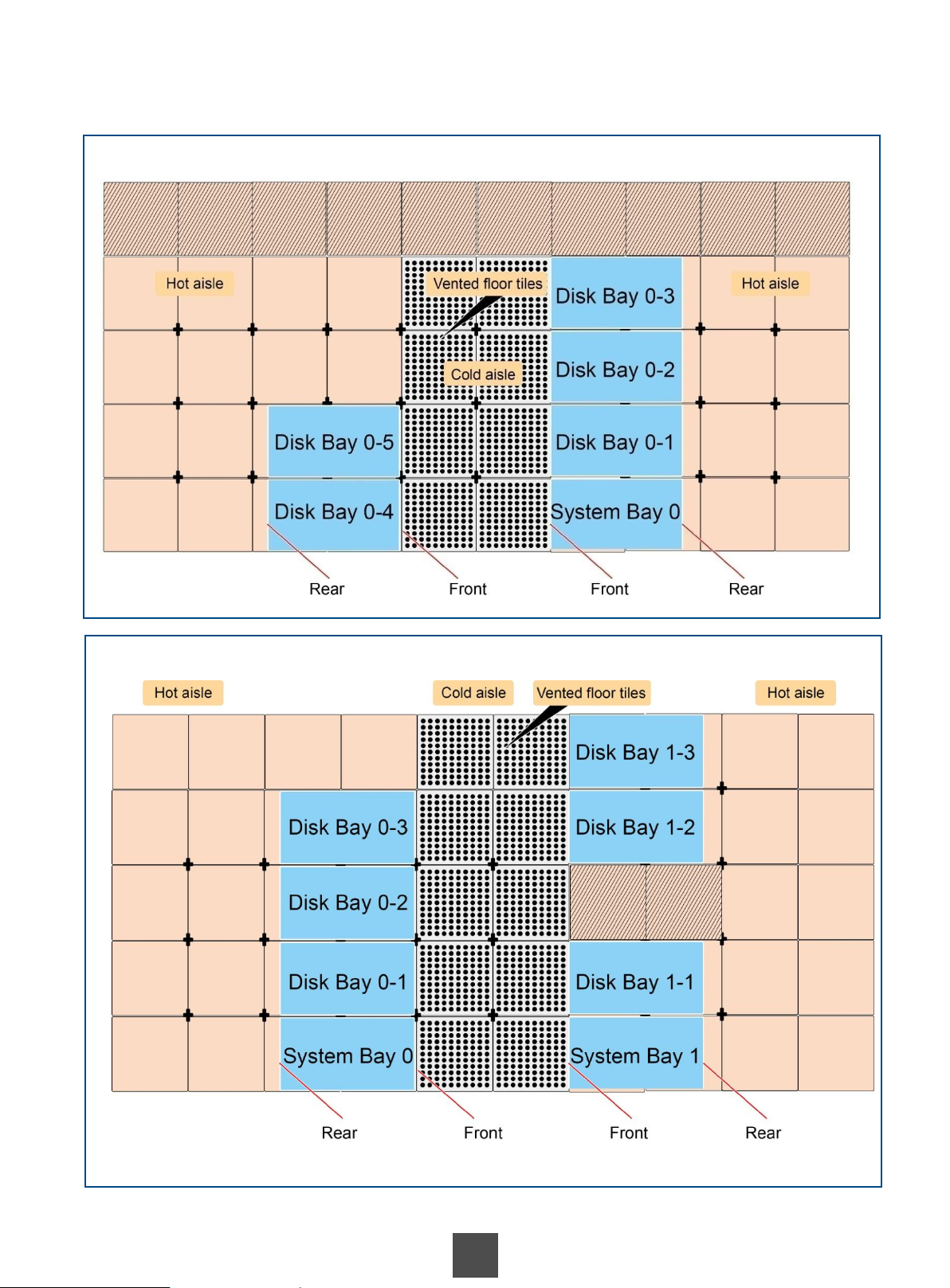
If system and disk bays cannot be placed in a row and the cables are long enough, you can place the system
and disk bays in two rows.
Scenario 1 Non-standard layout of 4 controllers
Scenario 2 Non-standard layout of 8 controllers
5
Page 6
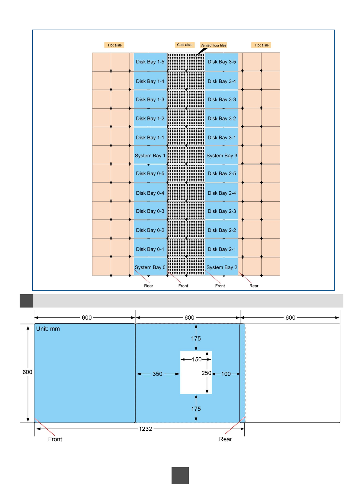
If the cables are long enough, you can use the following non-standard layout for 16-controller bays.
Scenario 3 Non-standard layout of 16 controllers
Planning positions of holes (for underfloor cabling only)
2b
Blue = Bottom of a system bay
White = Hole created in the equipment room
floor for cabling
1 inch = 25.4 mm
6
Page 7
2 Installing Bays
(Optional) Removing side panels
2c
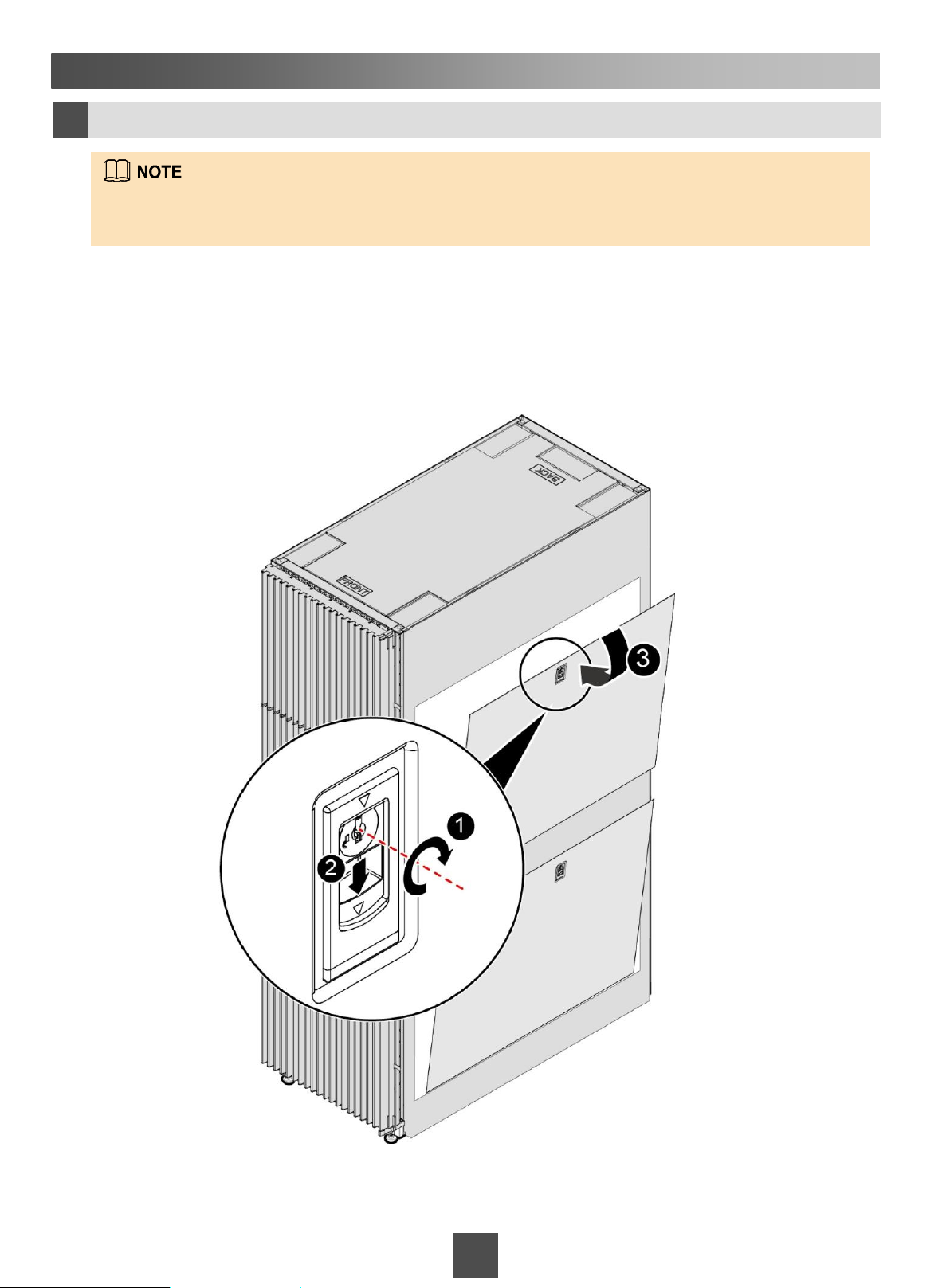
This is a required step when the storage system contains both a system bay and a disk bay. Remove
adjacent side panels from the two bays to allow for a direct SAS cable connection between them.
To remove a side panel, perform the following steps:
1. Insert the key delivered with the bay into the keyhole on the side panel and turn the key clockwise to open the
lock. Repeat for the other lock (locks on the front and rear doors and the side panels use the same key).
2. Use the handles below the two keyholes to pull the side panel away from the bay.
3. Remove the side panel.
7
7
Page 8
2 Installing Bays
Securing bays
2d
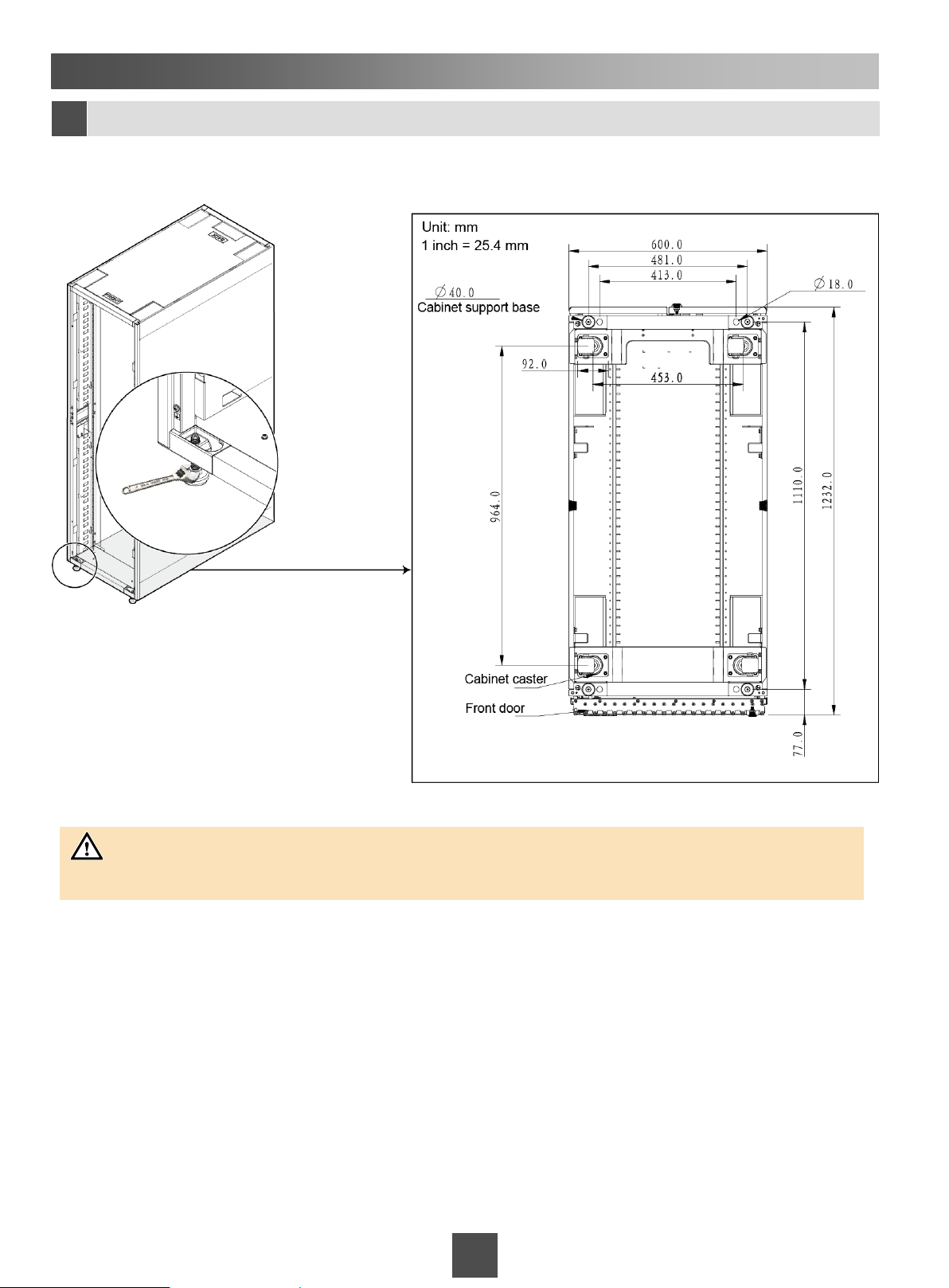
Move the bay to the desired location. Use an adjustable wrench to extend the leveling feet until the casters
no longer touch the ground and the bay is level.
Cabinet base
dimensions
NOTICE
Install the bays in the same row side by side.
8
8
Page 9
2 Installing Bays
(Optional) Connecting bays
2e
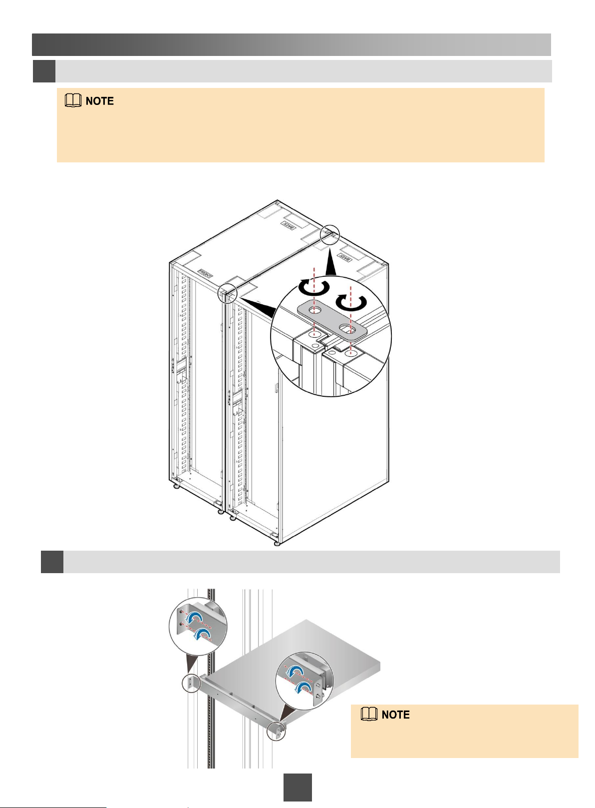
Connecting plates are delivered with the bays. Obtain the connecting plates at the bottom
of the bay near the rear door.
Connect two adjacent bays using two connecting plates (on the top of the bays).
Connect the two ends of a connecting plate to two neighboring bays using screws. Then fasten the other
connecting plates in the same way.
(Optional) Removing the KVM panel
2f
Loosen the two captive screws on each side of the KVM panel to remove the KVM panel.
If no KVM is configured for the storage
device, skip this step.
9
9
Page 10
3 Connecting Cables
Routing cables between bays
3a
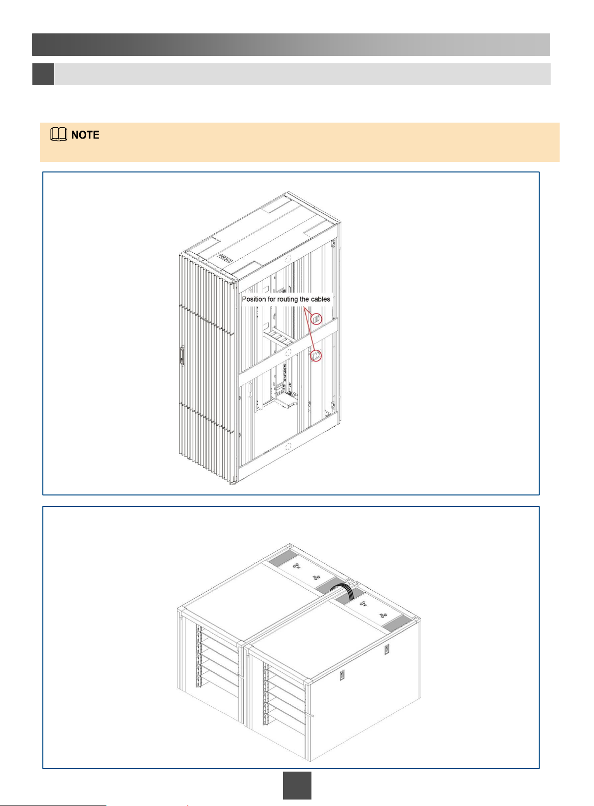
Route SAS cables (if both system and disk bays exist), network cables, optical fibers, and AOCs between bays
from sides or on the top of the bays.
You can also route the cables underfloor if there are cabling holes in the floor.
Scenario 1 Routing cables from cable holes on the two sides of the bay
Scenario 2 Routing cables on the top of the bays
10
10
Page 11

3 Connecting Cables
Connecting cables on the SVP and a controller enclosure
3b
Connects to the management network port of the controller enclosure.
Connects to the management network.
SVP
Connects to
a KVM.
Controller enclosure
Connects to
an SMS modem.
Connects to a
disk enclosure.
Connects to an
application server.
Connects to the
management network.
Connects to a data switch.
Connects to the SVP.
The SVP is optional. If the SVP is not delivered with the storage device, you must connect management
network port 0 of the controller enclosure to the management network.
11
11
Page 12
3 Connecting Cables
Connecting the SVP to controller enclosures or controller enclosures to
3c
management networks using network cables (for multiple system bays)
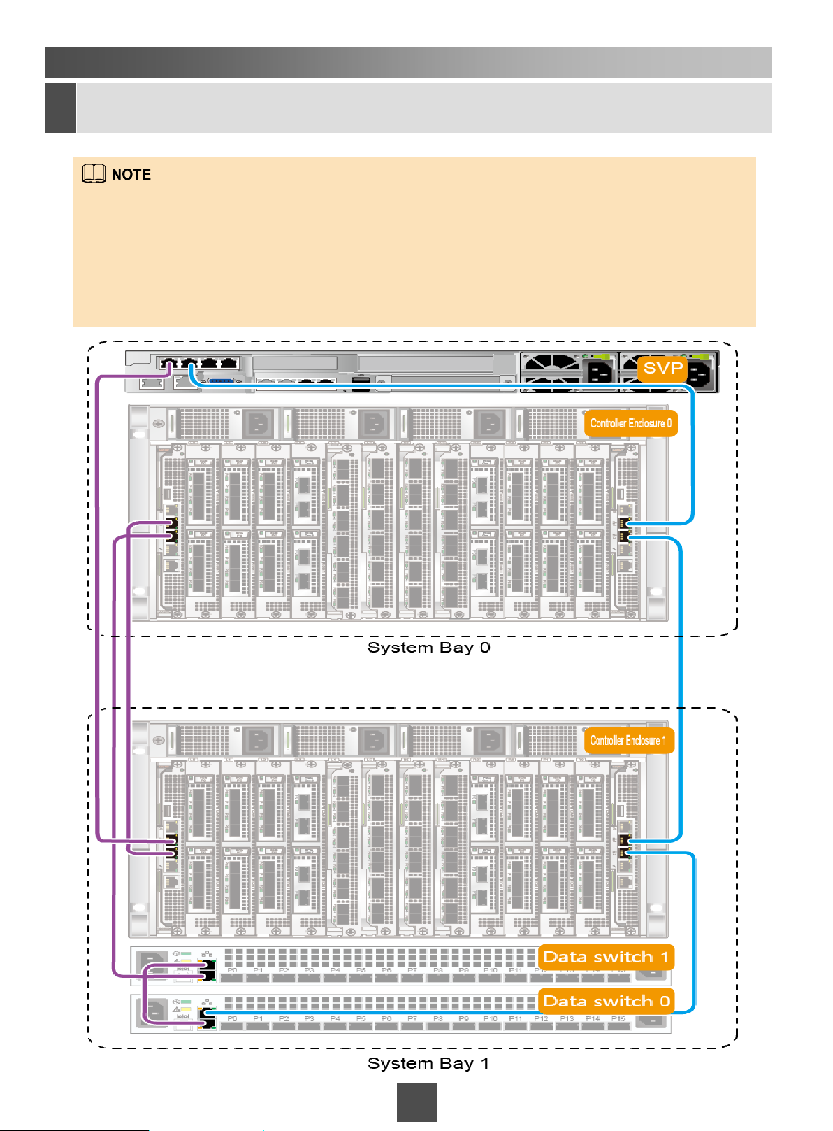
If your storage system has only one system bay, skip this step because the SVP and controller
enclosure are pre-connected before delivery. If your storage system has two or more system bays,
you must connect the management network ports on all controller enclosures to the SVP through
data switches in a loop.
The following describes how to connect cables in the scenario where a storage system has two
controller enclosures. In other scenarios, obtain help information from Enterprise Huawei Storage
Product Networking Assistant that is available at https://support.huawei.com/enterprise.
12
Page 13
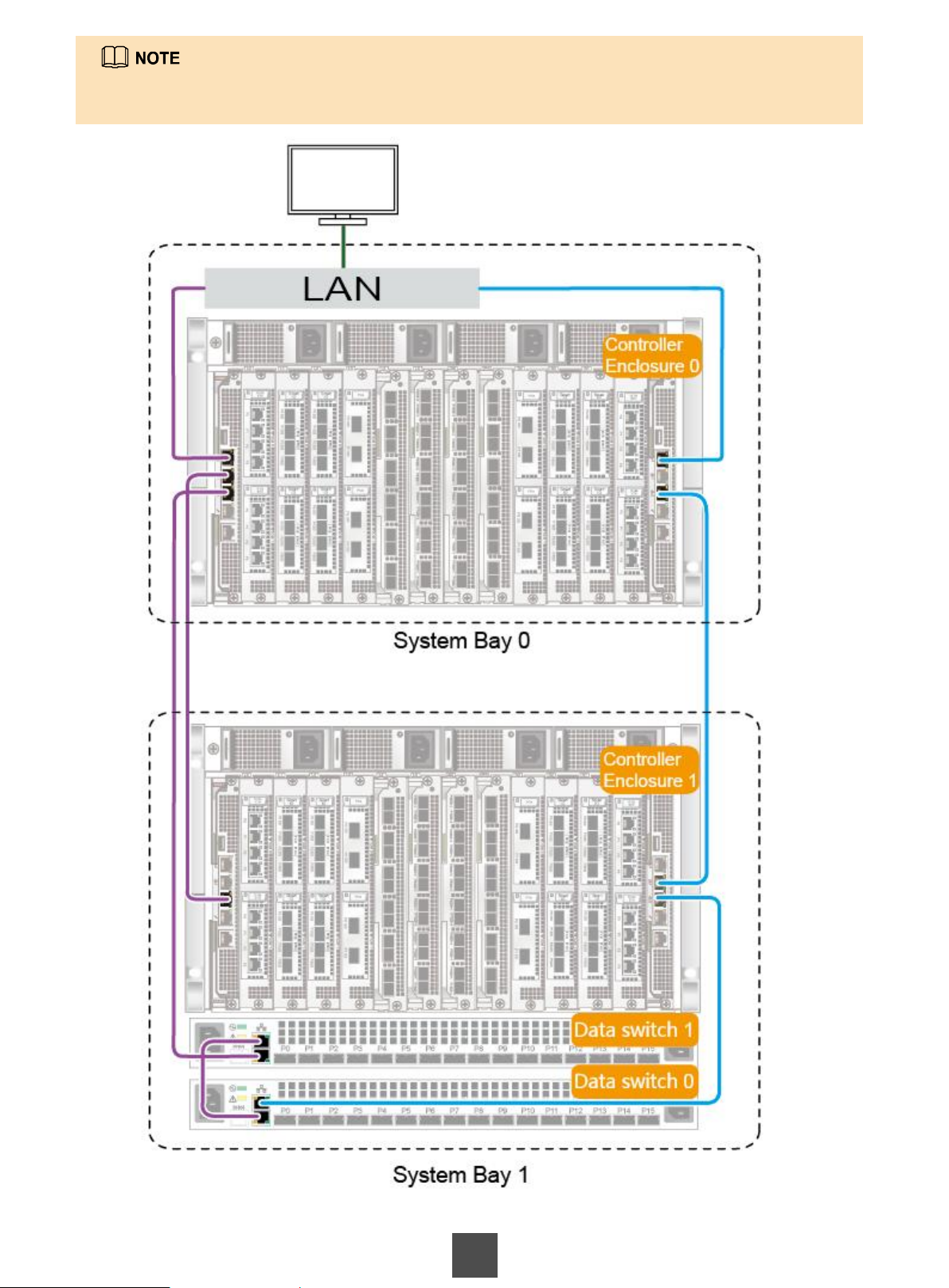
If the storage device is not configured with an SVP, the management network port of controller
enclosure 0 must connect to the management network.
13 13
Page 14
3 Connecting Cables
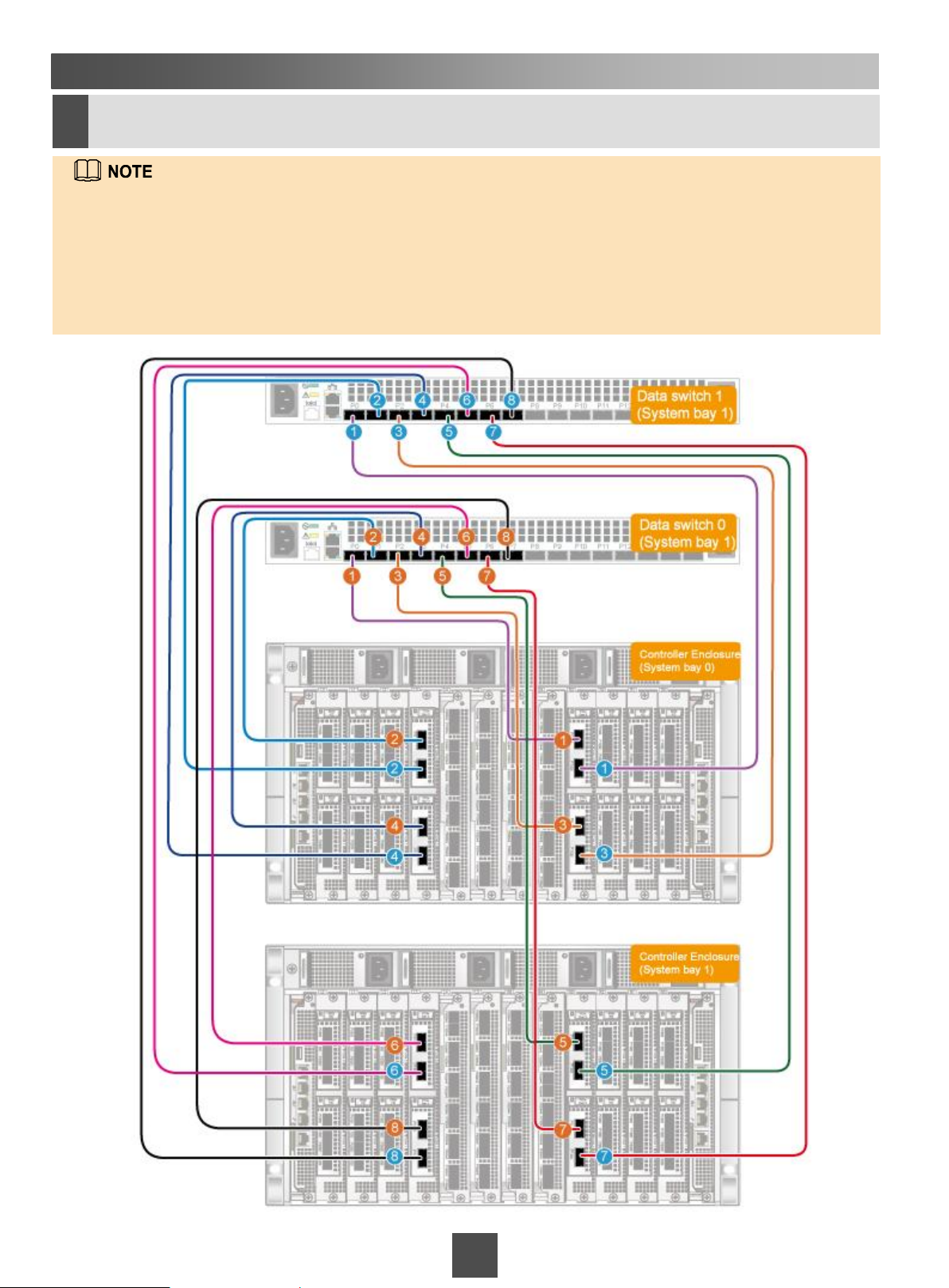
Connecting data switches to controller enclosures using AOCs (for
3d
multiple system bays)
If your storage system has only one system bay, skip this step. If your storage system has two or more
system bays, you must connect the controller enclosures in all system bays to the data switches in system
bay 1 using PCIe ports.
For further details about cable labels and cable routing, see Connecting Controller Enclosures to Data
Switches (Applicable to Two or More System Bays) in the OceanStor 18000 and 18000F V5 Series
V500R007 Installation Guide.
14
Page 15
3 Connecting Cables
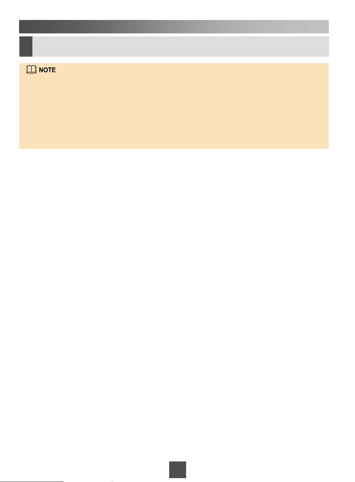
Connecting SAS cables (for a storage system with both system bays
3e
and disk bays)
If the disk bay is not in maximum configuration, comply with the following rules:
When connecting cables between two disk enclosures, connect the P0 port on one disk enclosure to the P1 port
on the other disk enclosure. When connecting a disk enclosure to a controller enclosure, connect the port on the
expansion module of the controller enclosure to the P0 port on the disk enclosure.
The SAS cables inside disk bays and system bays have been correctly connected before shipment.
The SAS cables between a disk bay and a system bay have been bound and connected to the disk bay before
delivery. At the site, you only need to connect the cables to the system bay according to the labels on the cables.
A SAS cable between a disk bay and a system bay is 15 meters long. Labels have been attached to the cables
before delivery. You do not need to prepare labels at site.
15 15
Page 16
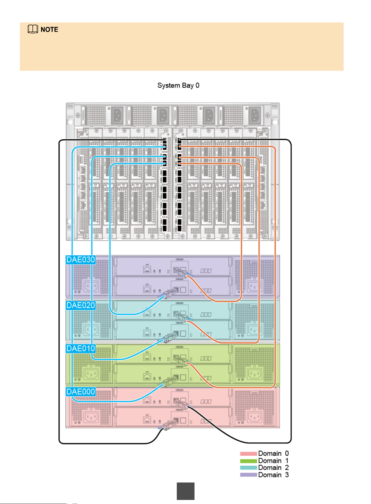
If the controller enclosure has two 12 Gbit/s SAS shared expansion modules, connect the ports on the
expansion modules to each disk enclosure in sequence, as shown in the following figure.
If the controller enclosure has four 12 Gbit/s SAS shared expansion modules, refer to the OceanStor 18000
and 18000F V5 Series V500R007 Installation Guide.
16
Page 17
3 Connecting Cables
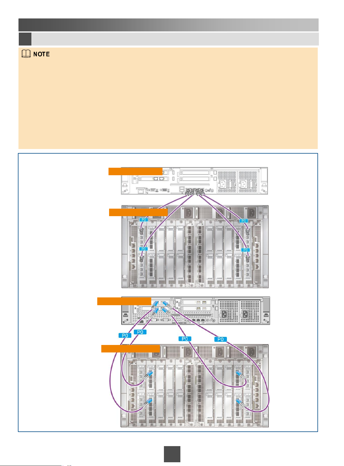
Connecting controller enclosures to application servers
3f
A controller enclosure can be connected to application servers using front-end ports (8 Gbit/s, 16 Gbit/s, or 32
Gbit/s Fibre Channel, 10GE, 10 Gbit/s FCoE, GE electrical, 10GE electrical, 56 Gbit/s InfiniBand, 25GE, 40GE,
or 100GE).
10GE electrical interface modules support GE/10GE auto-sensing.
The following figures are examples of cable connections. The details like cable appearance and types of
interface modules may be different from those at your site.
The following figures illustrate the network cable connection and optical fiber cable connection. If a storage
system is equipped with multiple system cabinets, connect the controller enclosures in the other system
cabinets to application servers as instructed in this section based on site requirements. For details about how to
connect front-end ports to an application server, see the OceanStor 18000 and 18000F V5 Series V500R007
Installation Guide.
Scenario 1 Directly connecting front-end ports to the application server
Network cable connection
Optical fiber cable connection
Application server
Controller enclosure
Application server
Controller enclosure
17 17
Page 18
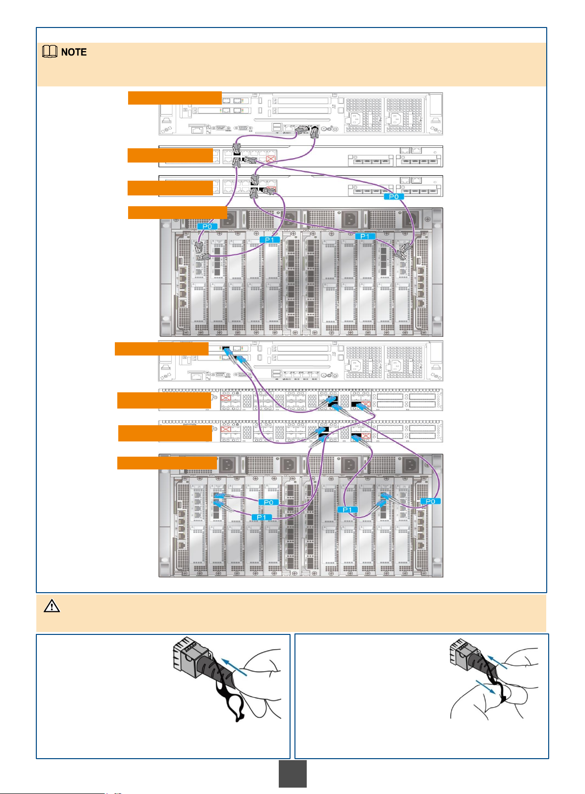
Scenario 2 Connecting front-end ports to the application server through switches
In the preceding network example, four redundant links connect to two controllers of a controller enclosure. The
networking of connections to four controllers is similar (that is, each controller connects to each switch).
Network cable
connection
Optical fiber
cable connection
Application server
Ethernet switch
Ethernet switch
Controller enclosure
Application server
Fibre Channel switch
Fibre Channel switch
Controller enclosure
NOTICE
Connect and remove high-speed cables as shown in the following figures.
Installing a high-speed cable Removing a high-speed cable
Insert the connector. After hearing a click, pull the
cable slightly. If the cable is not pulled out, the
connector is secured.
Push the connector slightly and pull the buckle as
shown in the figure to remove the high-speed cable.
18
Page 19
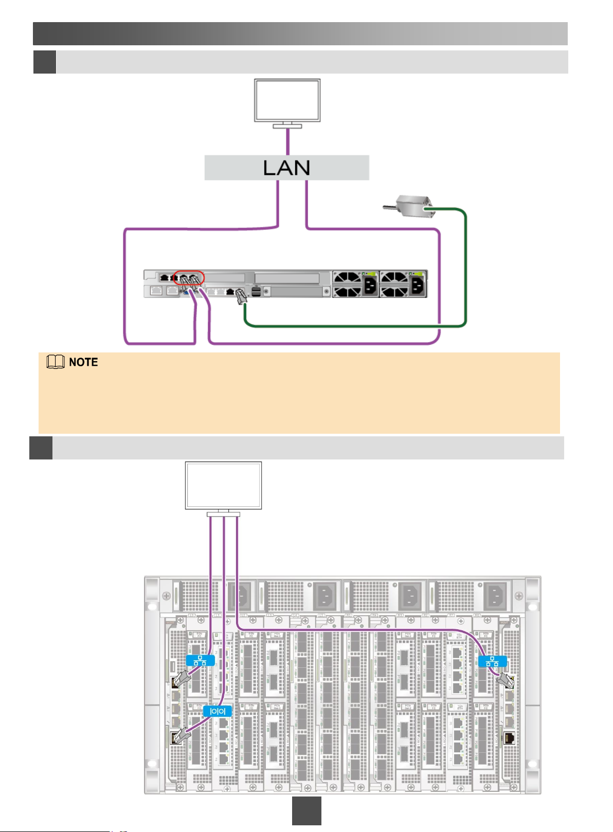
3 Connecting Cables
(Optional) Connecting the SVP to a maintenance terminal
3g
Maintenance terminal
SVP
SMS modem
The last two system management network ports on the SVP are bonded by default. The two ports have the same
IP address and the bonding cannot be removed. You are advised to connect both system management network
ports to the management network for link redundancy, thereby improving management network reliability. The red
box in the preceding figure indicates the positions of the two system management network ports.
If no KVM is configured for the storage device, skip this step.
Connecting the controller enclosure to a maintenance terminal
3h
Maintenance terminal
Controller
enclosure
19 19
Page 20
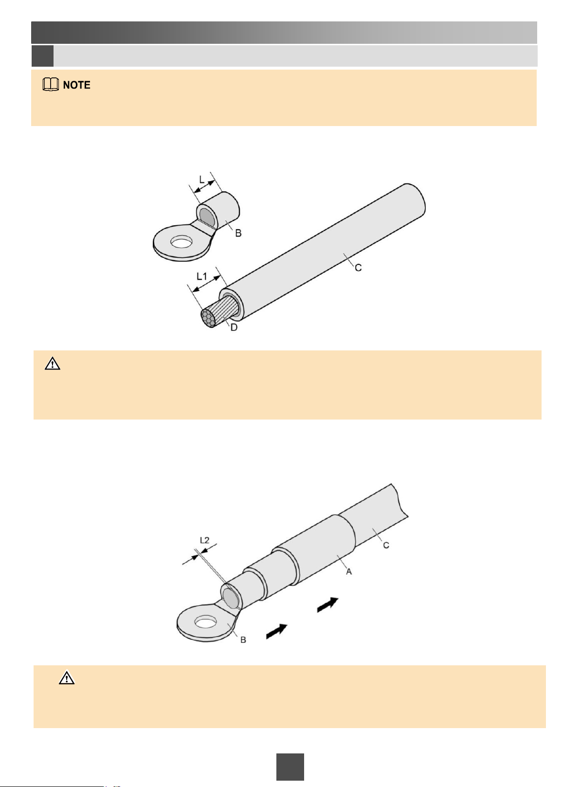
3 Connecting Cables
Connecting ground cables
3i
All devices in bays arrive pre-connected to ground terminals in the bays, use a ground cable to connect the
bay to a ground bar in the equipment room.
(1) Peel off a section of the insulation layer C from the ground cable to expose a section of ground cable
conductor D.
CAUTION
When peeling off the insulation layer of the ground cable, ensure that the conductor of the ground cable is not
scratched.
You can adjust L1 according to the length of the OT terminal. L1 = L + (1 to 2) mm (0.0394 or 0.0788 inch).
(2) Insert the ground cable into the heat shrink tube A. Insert the bare conductor of the ground cable into the OT
terminal B, and then press the OT terminal close to the insulation layer C.
CAUTION
After the OT terminal is installed, the length of the bare conductor outside the OT terminal (L2) must not be
greater than 2 mm (0.0788 inch). If L2 is greater than 2 mm (0.0788 inch), cut the redundant part by using the
diagonal pliers or wire clipper.
20
Page 21
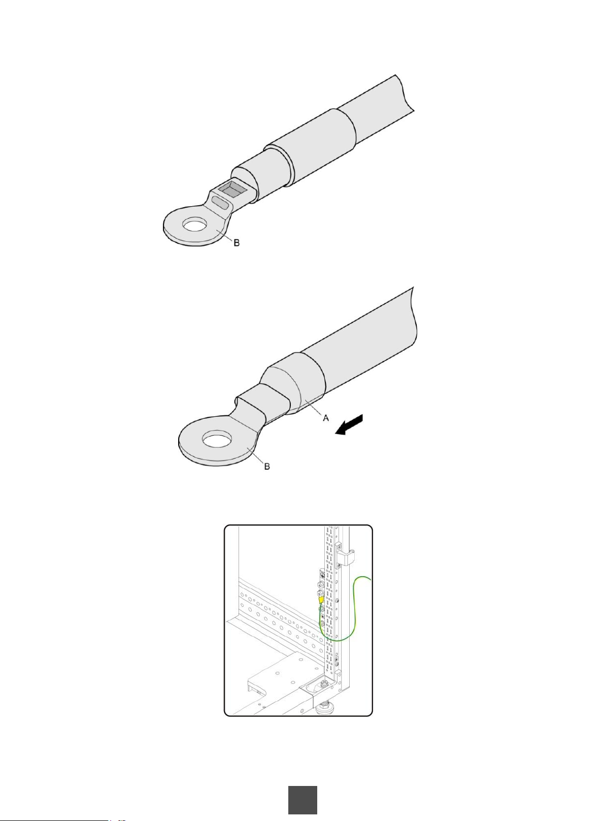
(3) Use the ground cable crimping tool to clamp the tail of the OT terminal and the contact part of the conductor.
(4) Push the heat shrink tube A towards the OT terminal, and cover the crimping area of the OT terminal and the
conductor. Use a heat gun to heat the heat shrink tube.
(5) Connect the OT terminal of the ground cable to one of the two upper ground terminals on the cabinet (in the
lower right corner of the rear door of the cabinet).
(6) Connect the other OT terminal of the ground cable to the ground terminal on the ground bar.
21
Page 22
3 Connecting Cables
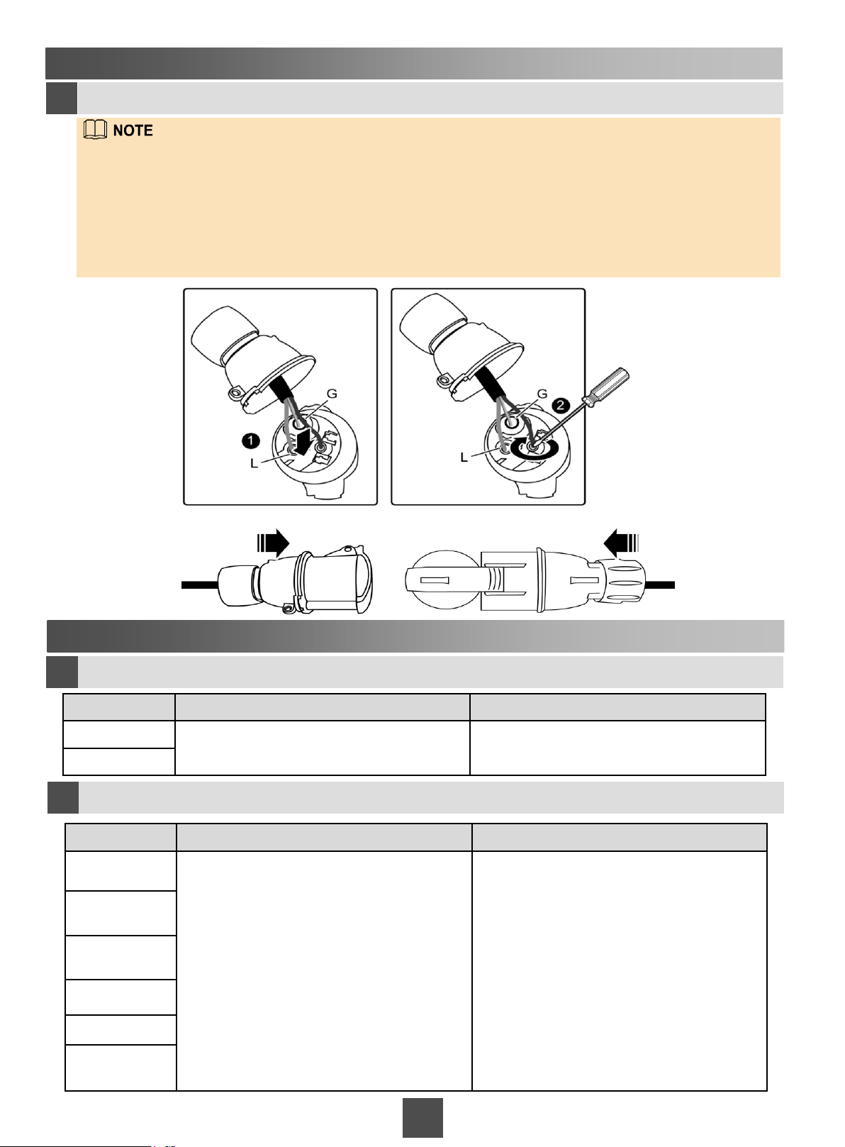
Assembling PDU connectors
3j
Power distribution unit (PDU) connectors are shipped with the storage system. Assemble the PDU
connectors, as shown in the following figures. After the external PDU power cable of a bay is connected,
bind the slack of the cable to the top or bottom of the bay. Skip this step if the pre-assembled PDU
connectors are already available.
Each PDU in a bay should be connected to an independent power supply. In a scenario where four
PDUs exist, four power supplies are required.
Connect the PDU connector to an external power source.
4 Inspecting Hardware Installation
Checking device installation
4a
Item Normal Abnormal
System bay
Disk bay
Checking cable connections
4b
Item Normal Abnormal
Optical fiber
Mini SAS HD
electric cable
The bay is stable on the ground. The bay slants or is misplaced.
Mini SAS HD
optical cable
AOC
Network cable
Power cable
The cables are securely fastened in the
ports.
22 22
The cables are loose or not connected
properly.
Page 23
5 Powering On the Storage System
Follow these basic rules to power on the storage system:
• For a storage system with both disk bays and system bays, first power on the disk bays and then the system bays.
• Power on the system bays in an ascending order from system bay 0 to system bay n.
• For a storage system with multiple controllers, power on all the controllers within three minutes.
To avoid electric shock, do not wear an ESD wrist strap during the power-on process.
Ensure that a storage system is properly grounded before powering it on to prevent the storage
system from being damaged.
Power-on procedure
5a
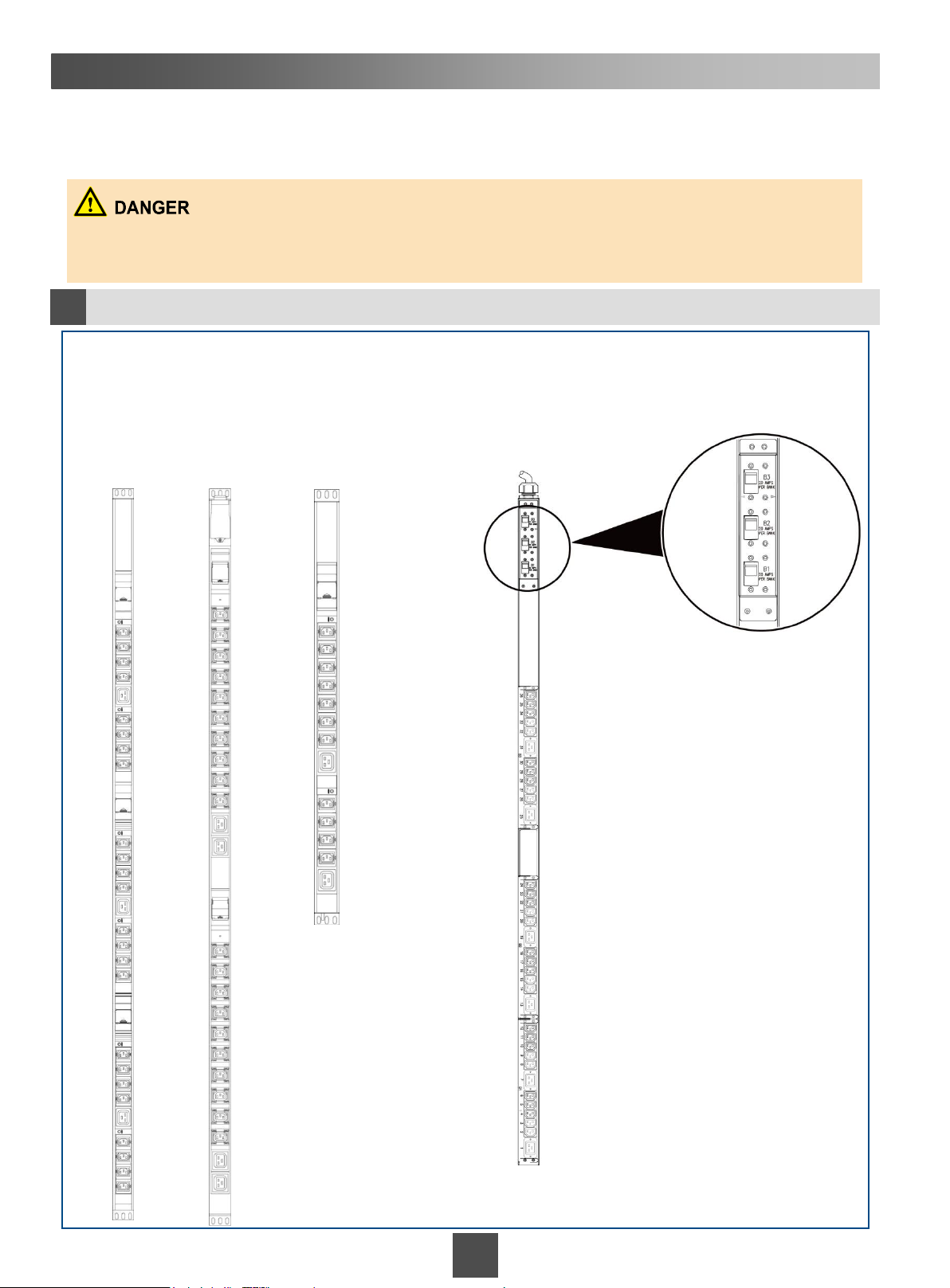
Scenario: When the cabinet uses AC power
Sequence of switching on PDUs: PDU switches on all disk bays → PDU switches on all system bays.
Powering on a storage system with European
standard PDUs
Three-phase
380 V 32 A
Single-phase
220 V 32 A
(disk bay)
Single-phase
220 V 32 A
(system bay)
Powering on a storage system with North
American standard PDUs
23
Page 24
5 Powering On the Storage System
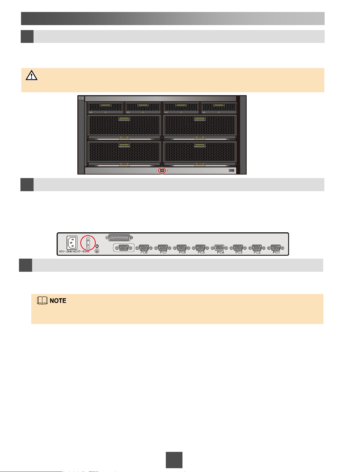
Pressing the power button on the controller enclosure
5b
Press the power button on the controller enclosure to power on the storage system. The disk enclosures will
automatically power on after the controller enclosure is powered on. The power-on of the storage system takes
15 to 30 minutes.
NOTICE
After a system is powered off, wait for at least 5 seconds to power it on.
(Optional) Powering on the KVM
5c
If the storage device is configured with the KVM but the KVM is not powered on, turn on the power switch
on the rear panel of the KVM to power it on (as shown in the red circle of following figure). After the KVM
is powered on, enter your user name and password to log in to the KVM console. The default user name
and password are empty. That is, you can log in to the system by pressing Enter twice. After the login,
select the channel that connects to the SVP to go to the Windows system (the default channel is 1).
Verifying that the storage system is powered on
5d
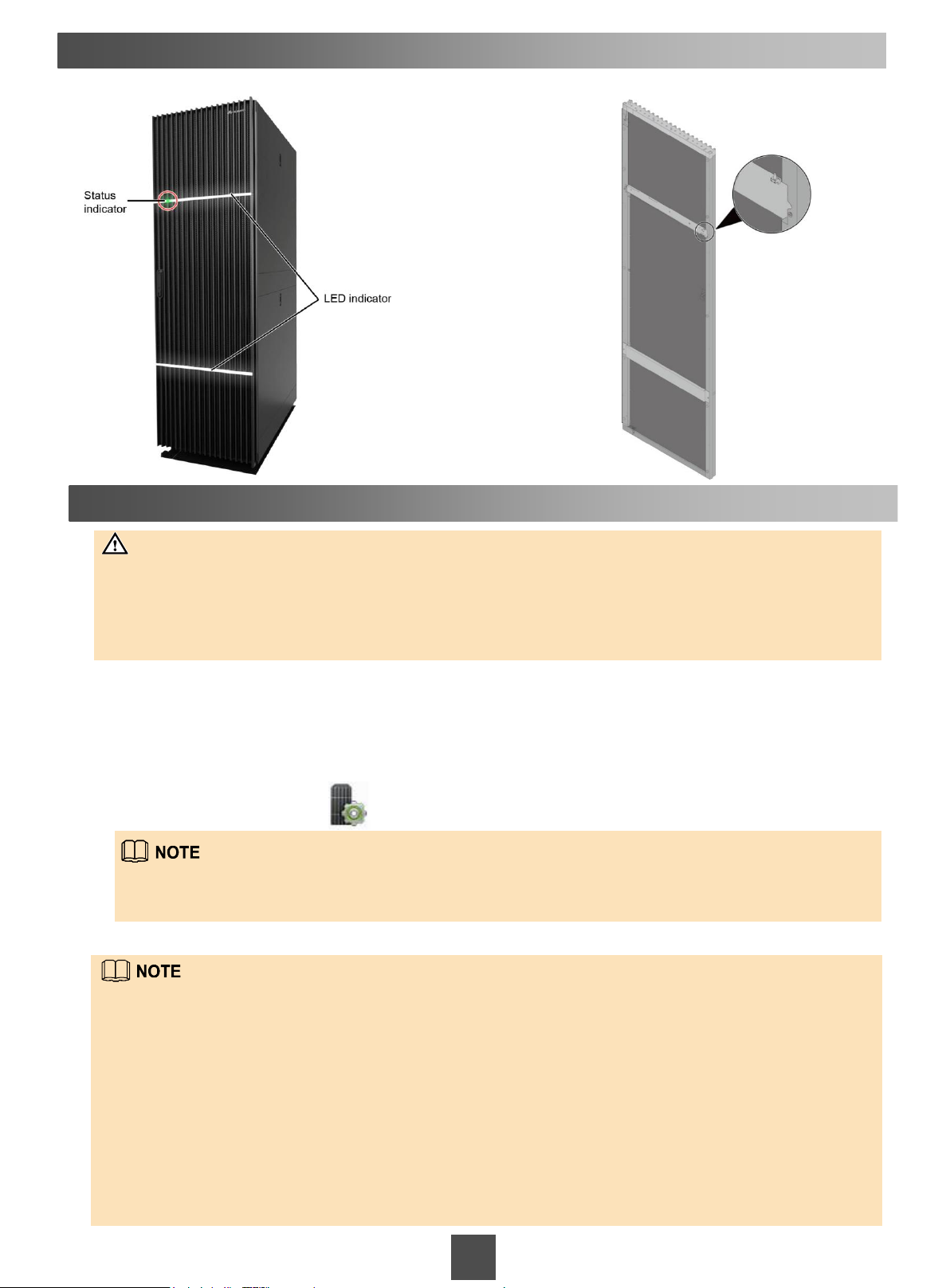
When the storage system is powering on, the status indicator on the front door of system bay 0 will blink
green. After the storage system has successfully powered on, the indicator will change to steady green.
The LED indicator is for decoration only. If you want to turn off the LED indicator, you can turn off the
LED indicator switch on the back of the cabinet's front door.
24
Page 25
5 Powering On the Storage System
Front door
6 Initializing the Storage System
Back of the front door
NOTICE
The SVP runs the management software and maintenance software that are delivered with the storage
system. They are critical storage system components. To prevent compatibility issues and function
failures, do not install any third-party software (such as antivirus software and packet capturing tools) or
uninstall the built-in software of the SVP. Third-party software installation and built-in software
uninstallation can result in storage system management failures and affect service stability and reliability.
After you have powered on the storage system, perform the following steps to initialize it:
1.Log in to the SVP and assign an IP address to the management network port.
2.Log in to the controller enclosure and assign an IP address to the management network port.
3.Change the login password of the SVP.
4.Log in to the OceanStor DeviceManager on the SVP.
a.On the desktop, double-click .
Your web browser may display a security certificate error. If the IP address is correct, you can neglect the prompt
and continue to access the storage system.
b.Type the user name and password in Username and Password.
If the storage device is not configured with an SVP, you can log in to the storage device using the IP address of the
management network port on the controller enclosure. For details, see the OceanStor 18000 and 18000F V5 Series
V500R007 Installation Guide.
For further details about how to initialize the storage system, see the OceanStor 18000 and 18000F V5 Series
V500R007 Installation Guide.
The default user name and password of the storage system are admin and Admin@storage.
You must change the default password immediately after you log in to the storage system for the first time and
periodically change your password in the future to maintain storage system security. The command to change password is
change user_password. For details about how to change the password in the DeviceManager, see the OceanStor 18000
and 18000F V5 Series V500R007 Administrator Guide.
For information about common user names and passwords involved in initializing the storage system, see Appendix.
25
Page 26
7 (Optional) Installing Host Software
Install the following host software on application servers:
1. BCManager eReplication. For details about how to install BCManager eReplication, refer to the OceanStor
BCManager eReplication User Guide.
2. UltraPath, a multipathing program. For details about how to install UltraPath, refer to the OceanStor
UltraPath for Windows User Guide, OceanStor UltraPath for Linux User Guide, OceanStor UltraPath for
Solaris User Guide, OceanStor UltraPath for AIX User Guide or OceanStor UltraPath for vSphere User
Guide.
Obtain the documentation related to the software from the Huawei technical support website.
Contacting Huawei Technical Support
If this document cannot help you resolve problems, contact Huawei technical support using one
of the following methods:
Huawei customer service center
Address: Huawei Industrial Base, Bantian, Longgang, Shenzhen 518129, People's Republic of China
Website: https://enterprise.huawei.com
Local Huawei technical support personnel
Obtain contact information for local Huawei offices at https://support.huawei.com/enterprise.
Huawei storage product information self-service platform
https://enterprise.huawei.com/topic/Self_service_2013_en/knowledge.html
26
Page 27
Appendix 1
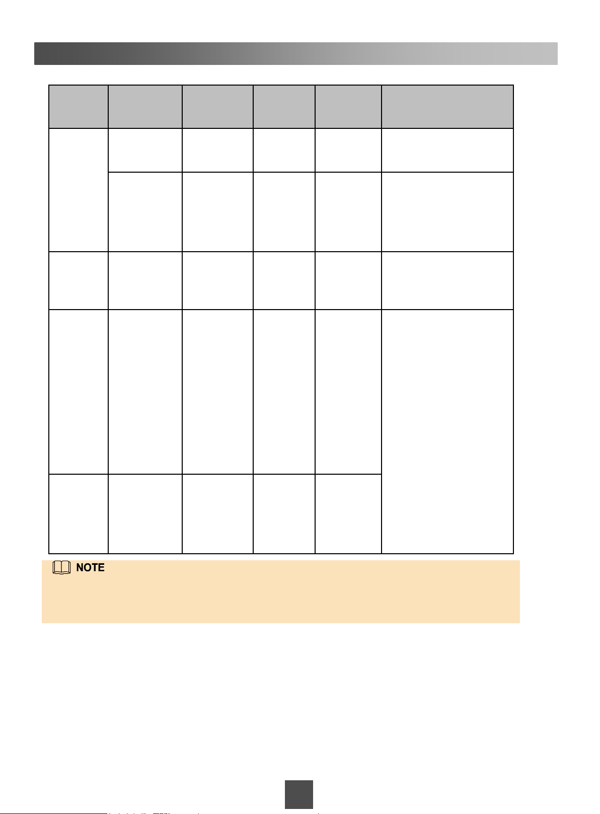
Information about common user names of initializing the storage system is shown as follows:
Account
Category
Built-in
SVP user
Built-in
iBMC
user
Built-in
controller
enclosure
user
User Level Usage Default
User
Name
Administrator Default user
for logging
in to HOST.
Administrator Default user
for logging
in to
Windows
VMs.
Administrator Default user
for logging
in to iBMC.
Super
administrator
The user
completely
controls the
storage
system and
can manage
users at the
same or a
lower level
and initialize
their
passwords.
svp_user Aguser@
maintainer Maintainer
Administra
tor
admin Admin@
Default
Password
12#$
@svp
Admin@90
00
storage
Password Changing
Method
Run passwd username to
change the password.
Change the password
using the password
changing method
provided by the Windows
operating system.
Log in to iBMC, choose
Configure > Local Users
on the iBMC to change
the user password.
For details about how to
change a password, see
section User
Management Solution in
chapter Installation
Planning in the
OceanStor 18000 and
18000F V5 Series
V500R007 Installation
Guide.
KVM - This is a
default user
account
used to
unlock KVM.
For more information about common user names and passwords involved in initializing the
storage system, see section User Management Solution in chapter Installation Planning in
the OceanStor 18000 and 18000F V5 Series V500R007 Installation Guide.
Null Null
27
Page 28
Appendix 2
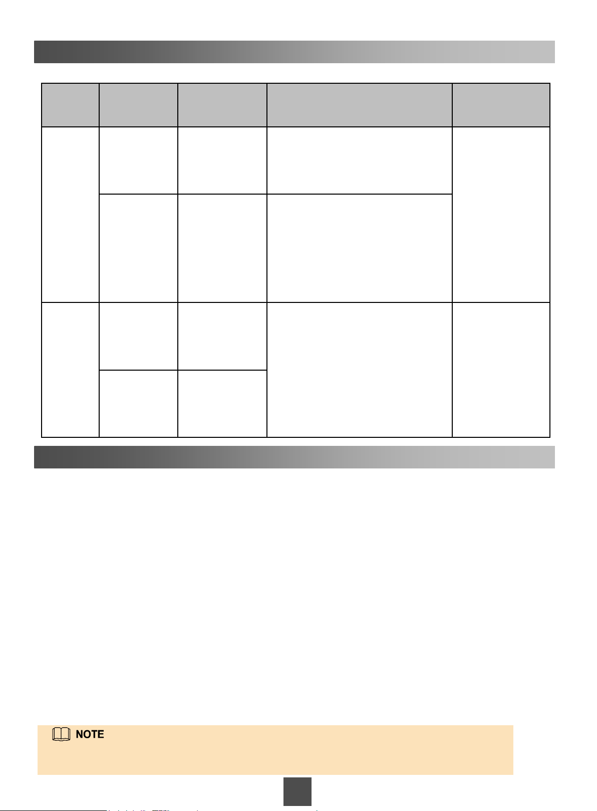
Information about the default IP addresses of the storage system is shown as follows:
Storage
Device
SVP Management
Controller
enclosure
Management
Network Port
network port
used to
manage the
SVP
Management
network port
Management
network port
of
management
module 0
Management
network port
of
management
module 1
Default IP
Address
192.168.2.100 The management network port used to
192.168.0.136 You can use the management network
192.168.128.101 You can log in to the storage system
192.168.128.102
Utility of the IP Address IP Address
manage the SVP is connected to a
maintenance terminal. You can use
the management network port to
remotely log in to and setting the SVP.
port to remotely log in to and setting
the SVP.
management page through the
management network port.
Setting Method
For details about
how to set the IP
address, see
section Setting IP
Addresses of the
SVP
Management
Network
Ports in the
OceanStor 18000
and 18000F V5
Series V500R007
Installation Guide.
Change the
management
network port IP
address through a
serial port, for
details, see the
change system
management_ip
command.
Appendix 3
The method for logging in to the Windows operating system built in the SVP is shown as follows:
If you use the KVM to operate the SVP, perform the following steps to log in to the Windows operating system
built in the SVP.
1. Log in to the SVP host as user svp_user. The default password is Aguser@12#$.
2. On the host desktop, choose Applications > System > Terminal > Xterm.
3. In the command window that is displayed, run vncviewer -fullscreen 127.0.0.1:1. The login page of the
Windows operating system built in the SVP is displayed.
4. Type the user name and password in the login page of the Windows operating system built in the SVP, and
press Enter. (The initial user name and password are maintainer and Maintainer@svp, respectively.)
If you visit the Windows operating system built in the SVP on a maintenance terminal using the RDP, perform
the following steps to log in to the Windows operating system built in the SVP. (The SVP's remote desktop
function requires network-level identity verification. Therefore, you must use operating systems and remote
desktop clients that support network-level identity verification to connect to the SVP. Windows XP and Windows
Server 2003 of certain versions do not support this function. You are advised to use Remote Desktop of Windows
7, Windows 8, or Windows 10.)
1. Choose Start > All Programs > Accessories > Remote Desktop Connection. The Remote Desktop
Connection dialog box is displayed.
2. Type the IP address of the management network port in the Computer text box and press Enter.
3. Type the user name and password to log in. The initial user name and password for logging in to the
Windows operating system built in the SVP are maintainer and Maintainer@svp respectively.
For more information about logging in to the storage system, see the OceanStor 18000 and
18000F V5 Series V500R007 Installation Guide.
28
Page 29
Product Statement
Supplier’s Declaration of Conformity (SDoC)
Unique Identifier:
trade name: HUAWEI; product name: Storage System;
model number: OceanStor 18000F V5
Responsible Party- U.S. Contact Information
Huawei Technologies USA Inc.
5700 Tennyson Parkway, Suite 500
Plano, Texas 75024
Main: 214-919-6000 / TAC Hotline: 877-448-2934
FCC Compliance Statement (for products subject to Part 15)
This device complies with part 15 of the FCC Rules. Operation is subject to the following two conditions: (1) This device
may not cause harmful interference, and (2) this device must accept any interference received, including interference that
may cause undesired operation.
29
 Loading...