

Page 1

HUAWEI
U-SYS MRS6100 Media Resource Server
Technical Manual
V100R002
Huawei Technologies Proprietary
Page 2

U-SYS MRS6100 Media Resource Server
Technical Manual
Manual Version
T2-020261-20051117-C-1.22
Product Version
V100R002
BOM
31026861
Huawei Technologies Co., Ltd. provides customers with comprehensive technical
support and service. Please feel free to contact our local office or company
headquarters.
Huawei Technologies Co., Ltd.
Address: Administration Building, Huawei Technologies Co., Ltd.,
Bantian, Longgang District, Shenzhen, P. R. China
Postal Code: 518129
Website:
http://www.huawei.com
Huawei Technologies Proprietary
Page 3

Copyright © Huawei Technologies Co., Ltd. 2006. All rights reserved.
No part of this document may be reproduced or transmitted in any form or by any
means without prior written consent of Huawei Technologies Co., Ltd.
Trademarks and Permissions
and other Huawei trademarks are trademarks of Huawei Technologies Co.,
Ltd.
All other trademarks and trade names mentioned in this document are the
property of their respective holders.
Notice
The information in this document is subject to change without notice. Every effort
has been made in the preparation of this document to ensure accuracy of the
contents, but all statements, information, and recommendations in this document
do not constitute the warranty of any kind, express or implied.
Huawei Technologies Proprietary
Page 4

About This Manual
Release Notes
This manual applies to the MRS6100 Media Resource Server V100R002 (the
MRS6100 for short).
Organization
The manual is organized as follows:
z Chapter 1 System Overview This chapter introduces the functions and
features of the MRS6100 and its position in NGN.
z Chapter 2 Hardware Structure This chapter introduces the hardware structure,
frames, boards, and typical configuration of the MRS6100.
z Chapter 3 Software Architecture This chapter introduces the overall
architecture, call processing system, and media processing system of the
MRS6100.
z Chapter 4 Media Resource Function This chapter introduces how to collect
and decode the DTMF signal, how the signal tone is generated and sent, how to
send the recorded voice announcement, audio conference, voice codec
algorithm conversion, voice recording, and video announcement.
z Chapter 5 MGCP and SIP This chapter introduces the MGCP and SIP
protocols and their applications with the MRS6100.
z Chapter 6 MRS6100 Terminal System This chapter introduces the
MRS6100 terminal system, the BAM server, operation and maintenance
workstation, emergency workstation, and the communication gateway software.
z Chapter 7 Operation and Maintenance This chapter introduces MRS6100
security management, data storage, data management, alarm management,
traffic statistics, and software patches.
z Chapter 8 Technical Specifications This chapter introduces technical
specifications of the MRS6100, including capacity, processing capability, power
supply and power consumption, and environment requirements.
z Chapter 9 Compliant Standards This chapter introduces the standards
followed by the MRS6100, including standards released by Ministry of
Information Industry of PRC, ITU-T, IEEE, and IETF
z Chapter 10 Reliability Design This chapter introduces the reliability design of
the MRS6100, including hardware design and software design.
z Appendix Acronyms and abbreviations
Huawei Technologies Proprietary
Page 5

Intended Audience
The manual is intended for the following readers:
z NGN planners
z NGN managers
z NGN system engineers
Conventions
The manual uses the following conventions:
I. General conventions
Convention Description
Arial Normal paragraphs are in Arial.
Arial Narrow
Warnings, Cautions, Notes and Tips are in Arial Narrow.
Boldface
Headings are in Boldface.
Courier New
Terminal Display is in Courier New.
II. GUI conventions
Convention Description
Boldface
Button names, menu items, window names, data table and
field names are in Boldface. For example, click OK.
->
Multi-level menus are in bold and separated by forward
slashes. For example, select the File -> Create -> Folder
menu.
III. Keyboard operation
Format Description
Key
Press the key with the key name in Boldface. For example,
Enter, Tab, Backspace, or A.
Key1+Key2
Press the keys concurrently. For example, Ctrl+Alt+A
means the three keys should be pressed at the same time.
Key1, Key2
Press the keys in turn. For example, Alt, A means the two
keys should be pressed in turn.
Huawei Technologies Proprietary
Page 6

IV. Symbols
Eye-catching symbols are also used in the manual to highlight the points worthy of
special attention during the operation. They are defined as follows:
Caution means reader should be extremely careful during the operation.
Note means a complementary description.
Environmental Protection
This product has been designed to comply with the requirements on environmental
protection. For the proper storage, use and disposal of this product, national laws and
regulations must be observed.
Huawei Technologies Proprietary
Page 7

Technical Manual
U-SYS MRS6100 Media Resource Server Table of Contents
Huawei Technologies Proprietary
i
Table of Contents
Chapter 1 System Overview.........................................................................................................1-1
1.1 System Functions .............................................................................................................. 1-1
1.2 System Networking............................................................................................................ 1-2
1.3 System Features................................................................................................................ 1-4
Chapter 2 Hardware Structure .....................................................................................................2-1
2.1 Logical Structure................................................................................................................ 2-1
2.2 Typical Configuration ......................................................................................................... 2-2
Chapter 3 Software Architecture .................................................................................................3-1
3.1 Overall Architecture ........................................................................................................... 3-1
3.2 Call Processing Subsystem ............................................................................................... 3-2
3.3 Media Processing Subsystem ........................................................................................... 3-3
Chapter 4 Media Resource Function...........................................................................................4-1
4.1 Collecting and Decoding the DTMF Signal........................................................................ 4-1
4.2 Generating and Sending Signal Tones.............................................................................. 4-1
4.3 Sending Recorded Announcements.................................................................................. 4-1
4.4 Audio Conference .............................................................................................................. 4-2
4.5 Converting Voice Codes .................................................................................................... 4-2
4.6 Recording........................................................................................................................... 4-2
4.7 Video Announcement ........................................................................................................ 4-2
Chapter 5 MGCP and SIP..............................................................................................................5-1
5.1 Using MGCP and SIP with the MRS6100 ......................................................................... 5-1
5.2 MGCP ................................................................................................................................ 5-1
5.2.1 Brief Introduction ..................................................................................................... 5-1
5.2.2 Terminologies that You Should Know..................................................................... 5-2
5.2.3 Protocol Stack ......................................................................................................... 5-8
5.2.4 Message Type......................................................................................................... 5-8
5.2.5 Message Structure ................................................................................................ 5-11
5.2.6 Call Flow................................................................................................................ 5-22
5.3 SIP ................................................................................................................................... 5-32
5.3.1 Basic Concepts ..................................................................................................... 5-32
5.3.2 Terms .................................................................................................................... 5-33
5.3.3 Protocol Stack ....................................................................................................... 5-36
5.3.4 Message Type....................................................................................................... 5-37
5.3.5 Message Structure ................................................................................................ 5-40
5.3.6 Call Flow................................................................................................................ 5-54
Page 8

Technical Manual
U-SYS MRS6100 Media Resource Server Table of Contents
Huawei Technologies Proprietary
ii
Chapter 6 MRS6100 Terminal System.........................................................................................6-1
6.1 System Overview............................................................................................................... 6-1
6.1.1 Structure of MRS6100 Terminal System ................................................................ 6-1
6.1.2 Structure of the Terminal System Software ............................................................6-1
6.2 BAM Server........................................................................................................................ 6-2
6.2.1 BAM Networking...................................................................................................... 6-3
6.2.2 Components of the BAM Software.......................................................................... 6-4
6.2.3 Characteristics of BAM............................................................................................ 6-5
6.3 Operation and Maintenance Workstation ..........................................................................6-8
6.4 Emergency Workstation..................................................................................................... 6-9
6.5 Communication Gateway Software ................................................................................. 6-10
Chapter 7 Operation and Maintenance........................................................................................7-1
7.1 Security Management........................................................................................................ 7-1
7.1.1 Command Group..................................................................................................... 7-1
7.1.2 Workstation Management ....................................................................................... 7-2
7.1.3 User Account Management..................................................................................... 7-2
7.1.4 Login Time............................................................................................................... 7-2
7.2 Data Storage...................................................................................................................... 7-3
7.2.1 BAM Data ................................................................................................................ 7-3
7.2.2 FAM System Data ................................................................................................... 7-3
7.3 Data Operation................................................................................................................... 7-4
7.4 Alarm Management ........................................................................................................... 7-6
7.4.1 Architecture ............................................................................................................. 7-6
7.4.2 Hardware Alarm Reporting Path ............................................................................. 7-7
7.4.3 Software Alarm Reporting Path............................................................................... 7-8
7.4.4 Alarm Levels............................................................................................................ 7-9
7.4.5 Alarm Types ............................................................................................................ 7-9
7.5 Traffic Statistics.................................................................................................................. 7-9
7.5.1 Traffic Statistics Type.............................................................................................. 7-9
7.5.2 Functions and Features of the Traffic Statistics System....................................... 7-10
7.6 Software Patch................................................................................................................. 7-12
7.6.1 Basic Concepts ..................................................................................................... 7-12
7.6.2 Features ................................................................................................................ 7-12
7.6.3 Structure................................................................................................................ 7-13
Chapter 8 Technical Specifications............................................................................................. 8-1
8.1 System Capacity ................................................................................................................ 8-1
8.2 System Processing Capability ........................................................................................... 8-1
8.2.1 Processing Capability.............................................................................................. 8-1
8.2.2 Delay Probability ..................................................................................................... 8-1
8.3 Physical Parameters.......................................................................................................... 8-2
8.4 Reliability Indexes.............................................................................................................. 8-2
8.5 Power Supply and Power Consumption ............................................................................ 8-2
Page 9

Technical Manual
U-SYS MRS6100 Media Resource Server Table of Contents
Huawei Technologies Proprietary
iii
8.6 Environment Requirements ............................................................................................... 8-4
8.6.1 Storage Environment .............................................................................................. 8-4
8.6.2 Transportation Environment....................................................................................8-6
8.6.3 Operating Environment ........................................................................................... 8-8
Chapter 9 Compliant Standards...................................................................................................9-1
9.1 PRC Standards.................................................................................................................. 9-1
9.2 ITU-T Standards ................................................................................................................ 9-1
9.3 IEEE Standard ................................................................................................................... 9-1
9.4 IETF Standards.................................................................................................................. 9-1
Chapter 10 Reliability Design.................................................................................................. ...10-1
10.1 Security .......................................................................................................................... 10-1
10.1.1 Network Security ................................................................................................. 10-1
10.1.2 System Protection ............................................................................................... 10-1
10.1.3 Data Security....................................................................................................... 10-1
10.1.4 Operation Security .............................................................................................. 10-2
10.2 Reliability........................................................................................................................ 10-2
10.2.1 Hardware Reliability ............................................................................................10-2
10.2.2 Software Reliability.............................................................................................. 10-3
Appendix A Acronyms and Abbreviations ................................................................................A-1
A
Page 10

Technical Manual
U-SYS MRS6100 Media Resource Server Chapter 1 System Overview
Huawei Technologies Proprietary
1-1
Chapter 1 System Overview
1.1 System Functions
The U-SYS MRS6100 Media Resource Server (the MRS6100 for short) is the core
resource component that provides value-added media services in the NGN. As the
core device, it implements the media resource function in 3G R5. The MRS6100
provides the following functions:
z Announcement
z Digit collecting
z Voice synthesis
z Voice recognition
z Recording
z Faxing
z Audio conference
z Video conference
The Control devices monitor the MRS6100, such as the SoftSwitch and the
application server (AS). In this way, the MRS6100 provides the special resource
functions for the services over the IP network. These functions include:
z Provide the resources
z Communicate with other entities
z Manage and maintain the resources
Page 11
Technical Manual
U-SYS MRS6100 Media Resource Server Chapter 1 System Overview
Huawei Technologies Proprietary
1-2
1.2 System Networking
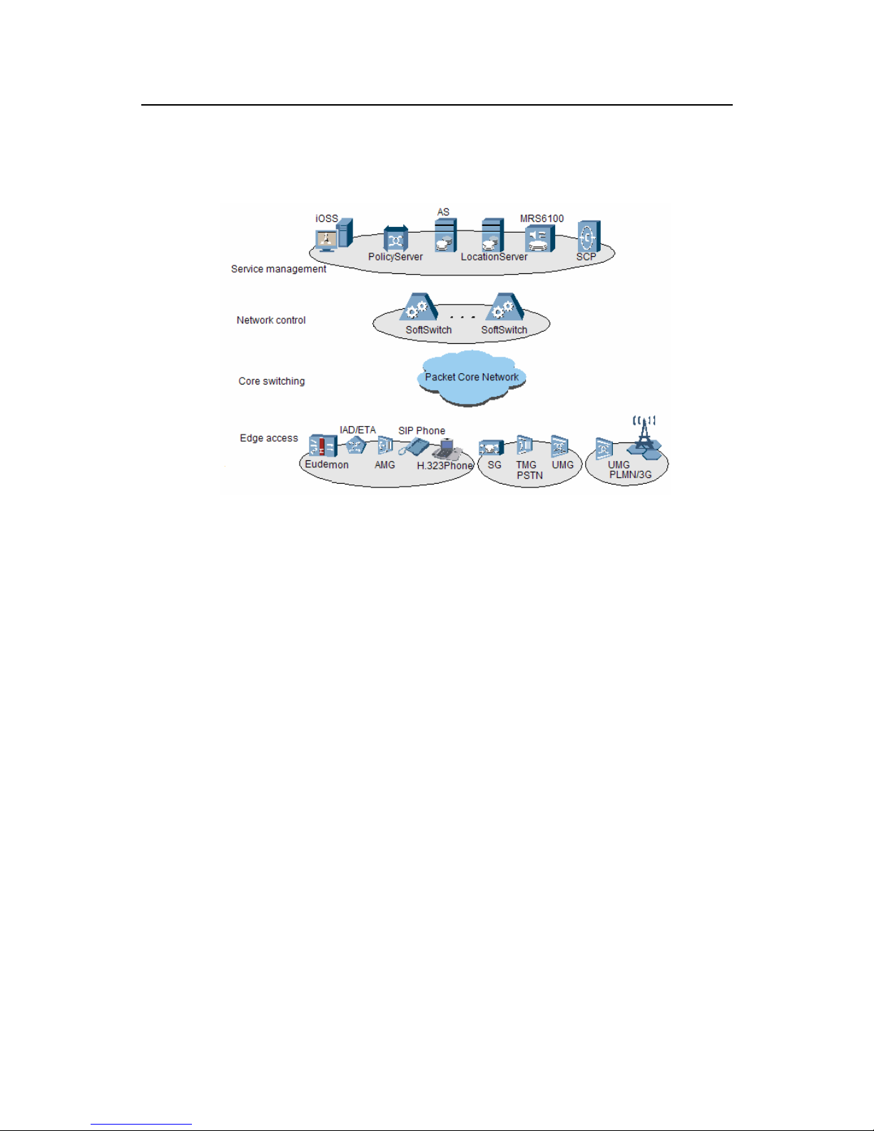
Figure 1-1 shows the MRS6100 in the NGN.
Figure 1-1 MRS6100 in the NGN
I. Service management layer
The service management layer provides value-added services and operation support
based on the established calls. It includes the following entities:
z MRS6100
It provides the media processing functions in the basic and enhanced services,
including service announcement, conference, interactive voice response (IVR),
notification, and advanced tone services.
z iOSS
The integrated operation support system (iOSS) includes the network
management system (NMS) and the integrated billing system.
z AS
The application server (AS) is a stand-alone device at the service management
layer. It provides the following functions:
1) Create and manage the logic related to the value-added services and
intelligent network services
2) Provide various open application programming interfaces (API).
3) Provide the development platform for the thirty-party services.
4) Separate service control from call control. This helps introduces new
services.
z Policy Server
It manages the policies for the following aspects:
Page 12

Technical Manual
U-SYS MRS6100 Media Resource Server Chapter 1 System Overview
Huawei Technologies Proprietary
1-3
1) Access control list (ACL)
2) Bandwidth
3) Traffic
4) Quality of Service (QoS).
z Location Server
It provides the following functions:
1) Mange the routing for the SoftSwitch devices in the NGN dynamically.
2) Indicate the accessibility of call destination.
3) Ensure high efficiency of the call routing table.
4) Reduce the complexity of routing.
z SCP
The Service Control Point (SCP) is the core component of the traditional
intelligent network. it stores the user data and service logic.
It provides the following functions:
1) Start different logic based on the call events reported by the Service
Switching Points (SSP).
2) Query the service database and user database based on the service logic.
z Send call control instructions to the related SSP to control its next action.
z Implement the intelligent calls.
II. Network control layer
The network control layer implements call control. It uses softswitch as core
technology to implement basic real-time call control and connection control.
As shown in
Figure 1-1, the SoftX3000 SoftSwitch is the core device in the NGN. It
implements the following functions:
1) Call control
2) Media gateway access control
3) Resource allocation
4) Protocol processing
5) Routing
6) Authentication
7) Charging
8) Provides basic voice services, mobile services, multimedia services, and APIs.
III. Core switching layer
The core switching layer adopts the packet technology. It is composed of the devices
like routers and layer-3 switches in the backbone network and the metropolitan area
network (MAN). It provides subscribers with a unified and integrated transmission
platform with high reliability, quality of service (QoS) assurance and a large capacity.
Page 13

Technical Manual
U-SYS MRS6100 Media Resource Server Chapter 1 System Overview
Huawei Technologies Proprietary
1-4
IV. Edge access layer
The edge access layer connects the subscribers and terminals with the network by
various access means. It converts the original information formats into those that can
be transferred over the network. The following devices can connect with the network:
z Integrated access device
The integrated access device (IAD) is a user access layer device in the NGN. It is
used to introduce the data, audio, and video services to the packet based
network.
z Access media gateway
The access media gateway (AMG) provides multi-service access, including
analog user access, integrated services digital network (ISDN), V5, and x digital
subscriber line (xDSL).
z SIP phone
The SIP phone is a kind of multimedia terminal device that supports the Session
initiation protocol (SIP).
z H.323 phone
The H.323 phone is a multimedia terminal device that supports the H.323
protocol.
z SG
The Signaling gateway (SG) connects the No.7 signaling network with the IP
network. It converts the N0.7 signaling of the public switched telephone network
(PSTN) and the signaling of the IP network.
z TMG
The Trunk media gateway (TMG) is located between the circuit switched network
and the IP packet switched network. It converts the formats between pulse code
modulation (PCM) signal streams and the IP media streams.
z UMG
The Universal media gateway (UMG) converts the media stream formats and the
signaling. It can act as a TMG, a built-in SG or an AMG. It can connect the
devices such as PSTN exchange, private branch exchange (PBX), access
network, network access server (NAS), and base station controller.
1.3 System Features
The MRS6100 provide the following features:
I. Open protocols and standard NMS interfaces
The MRS6100 supports open protocols like the SIP and the media gateway control
protocol (MGCP). It provides various interfaces to connect with the entities, such as
softswitch devices, AS, media gateways, IP intelligent terminals, and NM center. With
these interfaces, the MRS6100 can meet your special networking requirements.
Page 14

Technical Manual
U-SYS MRS6100 Media Resource Server Chapter 1 System Overview
Huawei Technologies Proprietary
1-5
z Open protocols
The MRS supports the following open protocols:
1) MGCP
2) SIP
3) Real-time transport protocol/RTP control protocol (RTP/RTCP)
4) Session description protocol (SDP)
5) Voice extensible markup language (VoiceXML or VXML) protocol, HTTP,
FTP, NFS and TCP/IP.
z The standard NMS interface is the man-machine language (MML) interface.
II. Large capacity and high integrity
z The MRS6100 supports up to 7200 voice channels to ensure smooth expansion.
z The MRS6100 supports up to 5,184,000 Busy Hour Call Attempts (BHCA).
z The MRS6100 uses standard frame, which is 9 U high, and 19 inches wide. This
ensures high integrity of the system.
III. High reliability design
The MRS6100 has the following reliability features:
z Supports redundancy design on the hardware and software.
For example, the MCCU and the SMUI use the “1+1” backup mode to ensure
high reliability of the devices.
z Provides auto-detection for faults and self-healing capability.
The MRS6100 can detect its hardware and software for faults automatically. if the
hardware or software is faulty, the MRS6100 reports alarms automatically. The
system then switches from the primary server to the secondary server to remove
the fault. If the fault cannot be removed, the system resets automatically for
recovery.
z Provide perfect protection functions against exceptions, including:
1) System power cut protection
2) System power switch protection against misoperation
3) Lightning protection for system power supply,
4) Overvoltage and undervoltage protection
5) Short circuit protection,
6) Overcurrent and overvoltage protection for power supply and interfaces
7) Internal temperature regulation and protection for power supply.
8) The system is protected when it receives any exceptional packet.
z Ensure data security
You can back up the system-class critical data to your hard disk or CDs,
including:
1) Device running parameters that you configure
2) Statistical information
3) Operator information
Page 15

Technical Manual
U-SYS MRS6100 Media Resource Server Chapter 1 System Overview
Huawei Technologies Proprietary
1-6
4) Administrator information
5) Logs.
z Ensure operation security
The MRS6100 ensure the system security on the following aspects:
1) Operator management
2) Login and logout control
3) Security control and protection
4) Operation logs.
5) Authority management
The MRS6100 authenticates the user before login and records the detailed operation
logs to ensure the system security and traceability.
IV. Handy and practical O&M functions
The MRS6100 provides the following handy and practical operation and maintenance
(O&M) functions:
z Flexible and diversified management modes
The MRS6100 provides you with multiple maintenance modes such as the
graphic user interface (GUI) client and MML You can set up your NMS network
flexibly based on the network structure, management requirements and
investment scale. The MRS6100 support multi-access to the system from local
or remote clients.
z GUI
The OMS uses the O&M interface with the navigation tree. The MML Client
works with the GUI to ease your O&M tasks.
z Powerful traffic statistics capability
The MRS6100 uses lists a graphics to analyze and display the performance data.
It monitors the real-time performance data and collects the background
performance data. The MRS6100 also can meet your customized traffic statistics
requirements.
z Real-time fault management
The MRS6100 receives and reports the faults about the network devices in real
time. It provides real-time audible and visible alarms through the topology, alarm
panel, or the alarm box. Also, the MRS6100 provides the fault management
system to report and filter leveled faults. This helps the carriers quickly locate
and remove the faults.
z Comprehensive help system
The online help is integrated in the MRS6100. You can retrieve the help system
whenever you want.
z Other functions
The MRS6100 also supports the following functions:
1) Install software patches online.
2) Debug the system online.
Page 16

Technical Manual
U-SYS MRS6100 Media Resource Server Chapter 1 System Overview
Huawei Technologies Proprietary
1-7
3) Maintain the system remotely.
4) Set the data dynamically.
5) Trace signaling and interfaces
6) Interpret the messages.
V. Smooth expansion
The MRS6100 features smooth expansion.
The hardware uses the modular structure. You can add new boards whenever you
want to expand the system capacity.
VI. Convenient update
z Easy to update
The MRS6100 setup interface features Windows style. It provides the similar
setup wizard. The default settings are most applicable. This helps you install,
upgrade or recover the system easily. The program design is separated from the
data design. This ensures that the updated system can inherit the legacy data.
z Safe to update
During the update, the MRS6100 setup program backs up the system database
in multiple modes several times to ensure system security. Also, the MRS6100
setup program backs up the loading files of the old version to ensure that the
system files can be restored to the old version if the new version fails to be
loaded.
z Online update
The MRS6100 provides uninterrupted online update for network services
z Separate update tool
The MRS6100 provides you with a separate tool to ensure update efficiency and
security.
Page 17
Technical Manual
U-SYS MRS6100 Media Resource Server Chapter 2 Hardware Structure
Huawei Technologies Proprietary
2-1
Chapter 2 Hardware Structure
2.1 Logical Structure
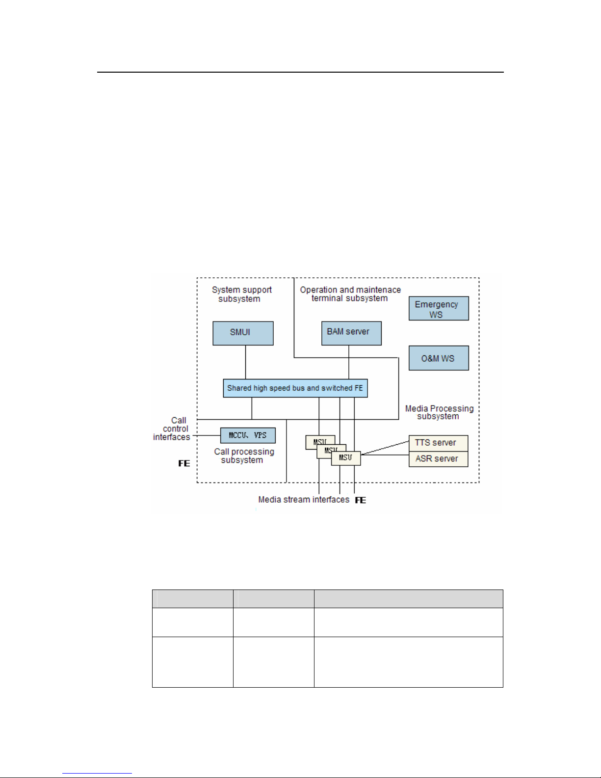
Logically, the MRS6100 hardware consists of the following subsystems:
z System support subsystem
z Call processing subsystem
z Media processing subsystem
z External O&M terminal
Figure 2-1 shows the logical hardware structure of the MRS6100.
Figure 2-1 MRS6100 hardware logical structure
Table 2-1 lists the buses for the MRS6100.
Table 2-1 MRS6100 buses
Bus Index Description
Shared resource
bus
4.8 Gbps
The bus is used for loading, data backup,
and system maintenance.
Switched fast
Ethernet (FE)
bus
Double-star
shaped, 100
Mbps
The signaling processing units and service
processing units use the Ethernet as
inter-board service communication channels
to ensure smooth service processing flow.
Page 18

Technical Manual
U-SYS MRS6100 Media Resource Server Chapter 2 Hardware Structure
Huawei Technologies Proprietary
2-2
I. System support subsystem
This subsystem loads the software or data, manages and maintains the devices, and
implements the inter-board communication.
It includes the System Management Unit (SMUI), the System Interface Unit (SIUI) of
the SMUI, and the Hot-Swap and Control Unit (HSCI).
z SMUI
The SMUI is the main control board of the frame. It loads the devices, configures the
data, and controls their working status.
z HSCI
The HSCI implements the bridging between the left and right shared resource buses,
board hot swap control, and intra-frame Ethernet bus switching.
The HSCI does not include a CPU. It is configured and maintained through the shared
resource bus by the SMUI.
II. Call processing subsystem
This subsystem provides the call processing function for the SIP and the MGCP.
The Media Call Control Unit (MCCU) resolves the SIP and the MGCP. The VPS
interprets the VXML script. The MCCU and the VPS communicates with the Media
Service Unit (MSU) through the internal Ethernet bus to control the MSU for media
processing.
III. Media processing subsystem
This subsystem processes the media streams, including
z RTP/RTCP
z Voice codec
z Conference bridge
z faxes
IV. O&M subsystem
This subsystem manages and maintains the entire system. It consists of the following
devices:
z Back Administration Module (BAM)
z Work Station (WS)
z Emergency WS
2.2 Typical Configuration
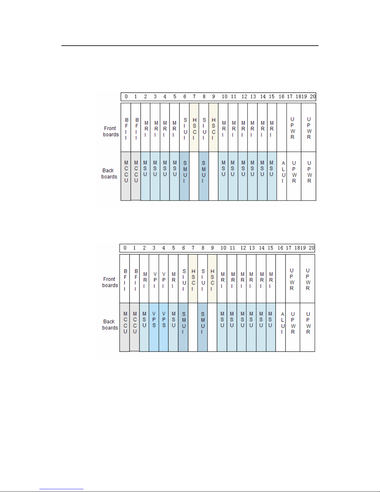
Figure 2-2 and Figure 2-3 shows the configuration of the MRS6100. The SMUI, SIUI,
HSCI, ALUI, MCCU, and the UPWR must be installed and fastened in the fixed slots.
Page 19
Technical Manual
U-SYS MRS6100 Media Resource Server Chapter 2 Hardware Structure
Huawei Technologies Proprietary
2-3
Each MSU can support up to 400 uncoded announcement voice channels or 240
codec IVR voice channels. You can configure the MSU as required.
I. Configuration without the VXML resolution unit
Figure 2-2 MRS6100 configuration without the VXML
II. Configuraiton with the VXML resolution unit
Figure 2-3 MRS6100 configuration with the VXML
Page 20
Technical Manual
U-SYS MRS6100 Media Resource Server Chapter 3 Software Architecture
Huawei Technologies Proprietary
3-1
Chapter 3 Software Architecture
3.1 Overall Architecture
The MRS6100 uses the hierarchical modular software architecture from the top down.
The design focuses on integration. This ensures that the system is highly reliable,
easy to maintain, and easy to expand. The MRS6100 is also a distributed software
system. It runs on the MCCU, MSU and the VPS.
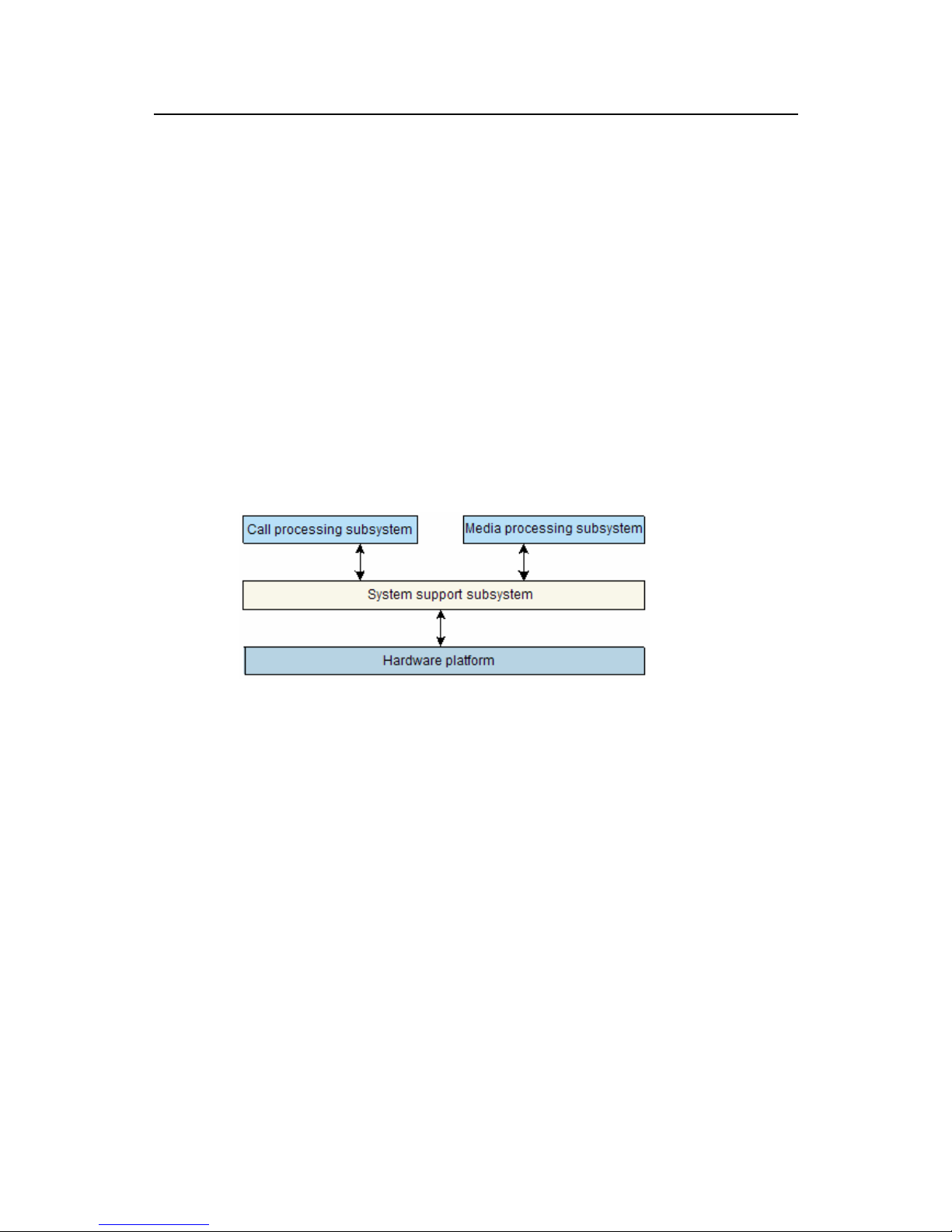
Logically, the MRS6100 software system consists of three modules:
z Call processing subsystem
z Media processing subsystem
z System support subsystem
Figure 3-1 shows the software architecture of the MRS6100.
Figure 3-1 MRS6100 software architecture
I. System support subsystem
This subsystem is the software platform of the MRS6100. It uses HUAWEI distributed
object-oriented programmable real-time architecture (DOPRA) platform middleware
to provide the application layer with the uniform APIs.
Also, the support subsystem provides the upper layer with the implementation
mechanisms on the following functions:
z O&M
z Alarm management
z Traffic statistics
z Signaling and user tracing
z Data backup
z Board switchover
z Online loading
Page 21
Technical Manual
U-SYS MRS6100 Media Resource Server Chapter 3 Software Architecture
Huawei Technologies Proprietary
3-2
II. Call processing subsystem
This subsystem interprets the MGCP, SIP, and the VXML scripts.
III. Media processing subsystem
This subsystem processes the media streams, including:
z Dual tone multi-frequency (DTMF) detection
z Audio record and announcement media streams
z Transcoding
3.2 Call Processing Subsystem
The MCCU board is responsible for call processing, including
z Lower layer interface processing
z Transport layer protocol processing
z Call control protocol processing.
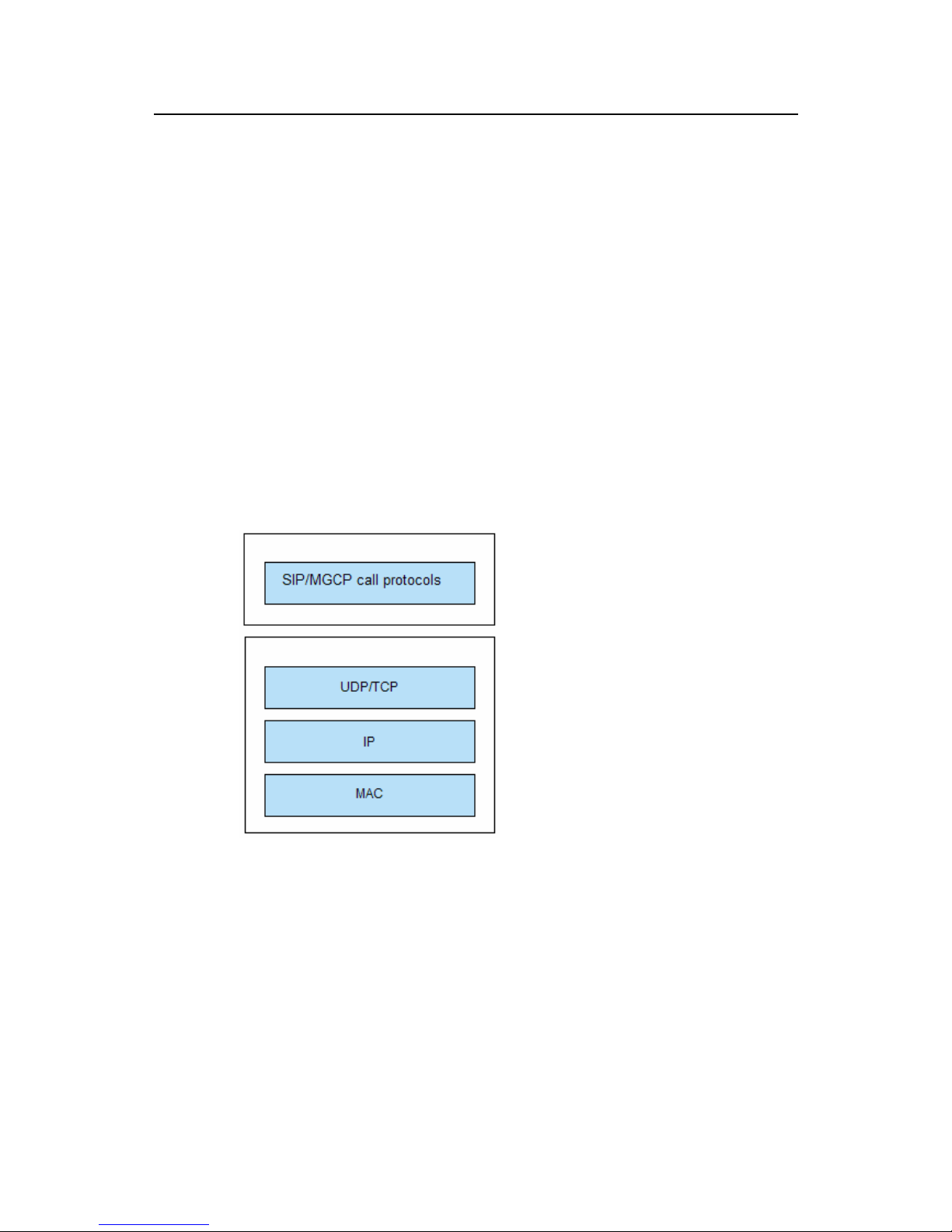
Figure 3-2 shows the software structure of the call processing subsystem.
Figure 3-2 Software structure
II. Lower layer interface processing
The Ethernet IP interface is the lower layer interface protocol of the call processing
subsystem. The MCCU board processes the media access control (MAC) protocol
and the IP packets.
Page 22

Technical Manual
U-SYS MRS6100 Media Resource Server Chapter 3 Software Architecture
Huawei Technologies Proprietary
3-3
III. Transport layer processing
The call processing subsystem processes the transport layer protocols like the UDP
and the TCP. These protocols bear the call control protocols like HTTP at the upper
layer over the IP network.
IV. Call control protocol processing
The MRS6100 supports the following call control protocols:
z MGCP
The MRS6100 processes the MGCP as follows:
1) Receive the call requests from the SoftSwitches.
2) Connect with the MGCP and the IAD or the AMG terminals.
3) Provide the announcement digit collecting or recording services for the terminals
based on the call requests sent by the SoftSwitches.
z SIP
1) Receive the call requests from the AS.
2) Connect with the SIP terminal.
z Provide the announcement digit collecting or recording services for the SIP
terminal based on the call requests sent by the AS.
z VXML
The MRS6100 process the VXML protocol as follows:
1) Receive the call requests from the AS.
2) Connect with the terminal.
3) Provide the announcement digit collecting or recording services for the terminals
based on the call requests sent by the AS.
3.3 Media Processing Subsystem
This subsystem performs the following tasks:
z Manage the media resources of the MRS6100.
z Control and process the service flows.
z RTP media stream transcoding.
z Provide the media processing resources for the external SoftSwitches or AS.
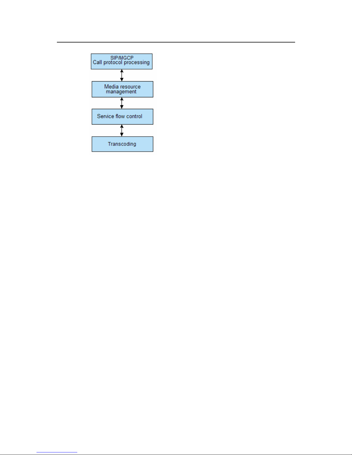
Figure 3-3 shows the software structure of the media processing subsystem.
Page 23
Technical Manual
U-SYS MRS6100 Media Resource Server Chapter 3 Software Architecture
Huawei Technologies Proprietary
3-4
Figure 3-3 Software structure of the media processing subsystem
I. Media resource management
The MRS6100 allocates and manages its resource through the media resource
management module. This module provides the following functions:
z Allocate the channel and conference resources to each SIP/MGCP call
z Reserve the resources.
z Recover the resources when the connection is released.
II. Service flow control
The MRS6100 serves as a media resource pool. It provides media services to the AS
or SoftSwitches. The MRS6100 also controls the service flows to simplify the
operation and control on the AS and SoftSwitches.
III. Media processing
Media processing includes:
z Transcoding
z Announcement
z Digit collecting
z Mixing
z Recording.
Page 24

Technical Manual
U-SYS MRS6100 Media Resource Server Chapter 4 Media Resource Function
Huawei Technologies Proprietary
4-1
Chapter 4 Media Resource Function
4.1 Collecting and Decoding the DTMF Signal
The MRS6100 can monitor the DTMF signal in the RTP voice payload or the RTP
payload in RFC2833 format.
The MRS6100 receives the DTMF signal from the DTMF phone under the control of
the AS or SoftSwitches. It recognizes the dialed number. Then, the MRS6100
converts the number into the related digits and encapsulates it in the signaling to
transfer it to the AS or SoftSwitch.
Based on the digit map delivered by the service logic, the MRS6100 receives the input
information. If the input digit sequence matches a digit template in the digit collecting
templates, the MRS6100 reports an event and the input data to the service logic. If the
digit sequence does not match any digit template in the digit map, this digit sequence
is invalid.
Also, the MRS6100 can receive the input information based on the special functional
keys delivered by the service logic. According to the definitions of the keys, the
MRS6100 interacts with the user.
4.2 Generating and Sending Signal Tones
The MRS6100 can recognize signal tone identifiers from the SoftSwitches or AS.
Then, it generates the related signal tones, such as dial tone or busy tone to the user.
These signal tones comply with the YDN 065-1997 specifications.
4.3 Sending Recorded Announcements
The MRS6100 plays the recorded announcements to the user in a specified voice
code format based on the requirements of the control device. The announcement
code can be G.711 A/u, G.729A, or G.723.1. The recorded announcements can be
loaded onto the boards of the MRS6100 or stored on the FTP server. Each MSU
board of the MRS6100 can load 200 MB audio files. The audio files on the server are
limited only by the space of the server.
In addition, the MRS6100 can play variable voices in a specified format. The voice
format and value are specified by the service logic.
Page 25

Technical Manual
U-SYS MRS6100 Media Resource Server Chapter 4 Media Resource Function
Huawei Technologies Proprietary
4-2
4.4 Audio Conference
Under the control of control devices, the MRS6100 provides the multiparty conference
function. It supports multi-coded terminals at the same time. The organizer can
control the conference in real time.
The MRS6100 supports IP based audio conference. The MRS6100 audio conference
function has the following features:
z Support up to 120 parties in a conference.
z Support up to 2,400 three-party conferences.
z Provide the recording and announcement functions for the conference.
z Provide the recording, announcement, and digit collecting functions for a party in
the conference.
z Provide the enhanced control function over the conference.
4.5 Converting Voice Codes
The MRS6100 supports various voice codec algorithms such as G.711A/u, G.723.1,
G.726, and G.729A. It can convert the codec algorithms as required.
4.6 Recording
The MRS6100 supports recording for a channel or for the conference. It supports
several audio file formats, such as G.711A/u and G.729A. The recorded audio files are
stored in the specified directory on the FTP server.
4.7 Video Announcement
Under the control of the SoftSwitches or AS, the MRS6100 provides the video
announcement function. This function has the following features:
z Support multiple video codes, such as H.263.
z Support multiple image formats, such as CIFand QCIF.
z Support multiple video rates ranging from 64 kbps to 384Kbps.
Page 26
Technical Manual
U-SYS MRS6100 Media Resource Server Chapter 5 MGCP and SIP
Huawei Technologies Proprietary
5-1
Chapter 5 MGCP and SIP
5.1 Using MGCP and SIP with the MRS6100
Figure 5-1 Using the MGCP and SIP with the MRS6100
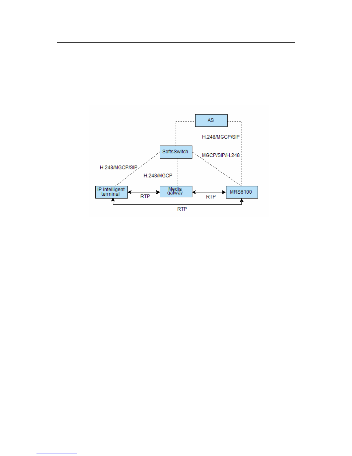
As shown in
Figure 5-1, the MRS6100 can be controlled by the SoftSwitch or the AS.
The control protocols include the MGCP, SIP, and the H.248.
z Under the control of the SoftSwitch, the protocols are used in the services
provided by the SoftSwitch, such as basic call services and supplementary
services.
z Under the control of the AS, the protocols are used in the services provided by
the AS, such as conferences, voice e-mail, and uniform communications.
5.2 MGCP
5.2.1 Brief Introduction
RFC2705 defines the API and the related MGCP. The MGCP is used to control the
voice over IP (VoIP) gateways from external call control units.
The MGCP defines a call control structure. In this structure, call control is separated
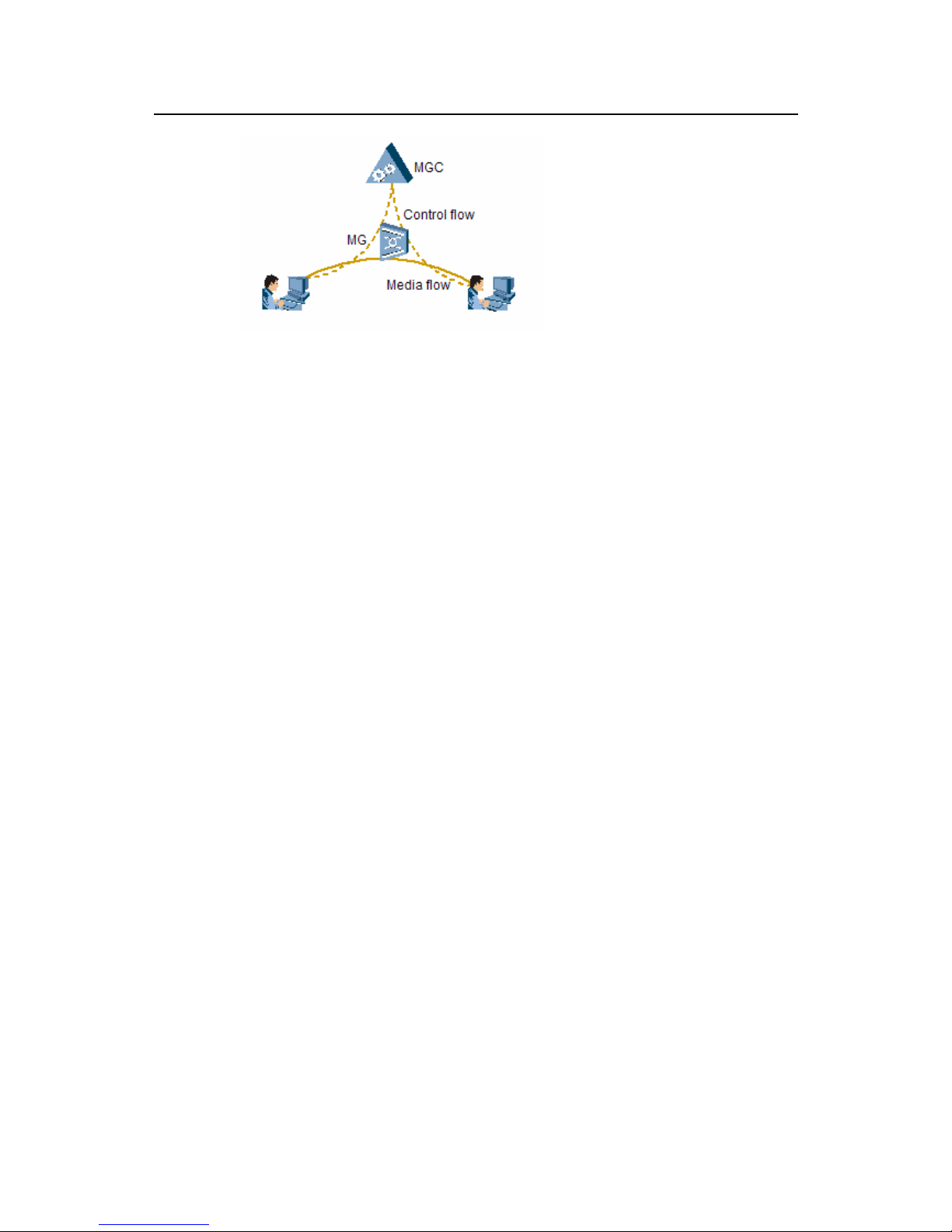
from the service bearer. As shown in
Figure 5-2, the call control function is separated
from the media gateways (MG). The function is implemented by the external call
control unit, such as the media gateway controller (MGC) or the call agent (CA). The
MG executes the commands sent from the MGC. Therefore, the MGCP is essentially
a master/slave protocol.
Page 27
Technical Manual
U-SYS MRS6100 Media Resource Server Chapter 5 MGCP and SIP
Huawei Technologies Proprietary
5-2
Figure 5-2 MGCP
5.2.2 Terminologies that You Should Know
I. Gateway
The gateway is a network element that implements interconnection and interworking
between networks with different architectures. In the NGN, the NGN interconnects
with other networks through the gateways likes TMG, AMG, or UMG.
II. Call agent
The call agent (CA) provides signaling and call processing functions. It is an external
call control element used to control the telephony gateways.
III. Endpoint
The endpoint is the data source or data sink. It can be a physical link or a virtual link
running on the physical link.
For example, the interface through which the trunk gateway terminal connects with
the PSTN exchange and the E-phone interface that the access gateway connects are
physical endpoints. The audio source in the MRS is a virtual endpoint.
To create a physical endpoint, you need to install the related hardware. To create a
virtual endpoint, you do not need to do so. You can use the related software to create
a virtual endpoint.
IV. Endpoint identifier
Endpoints are identified by endpoint identifiers. Endpoint identifiers are not case
insensitive.
An endpoint identifier consists of two parts:
z The local name of the endpoint in the gateway, and
z The domain name of the gateway.
Page 28

Technical Manual
U-SYS MRS6100 Media Resource Server Chapter 5 MGCP and SIP
Huawei Technologies Proprietary
5-3
The two parts are separated by @, for example, ms/cnf/1@ mrs6100.huawei.com.
The syntax of the local name depends on the type of the endpoint. The local name
can be leveled to forma naming path from the gateway name to other endpoints.
An endpoint identifier must comply with the following conversions:
z Each identification item in the naming path must be separated by a slash (/).
z Each identification item must be letters, numbers or other printable characters.
The item cannot include delimiters like /, @, or space.
z Wildcards like * or $ can be used in local names. * represents all the endpoints
above this level; $ represents one endpoint above this level.
In the MGCP, the gateway is identified by the domain name, for example,
mrs6100.huawei.com. The local name can consist of a physical interface name, for
example ms/cnf, and a terminal identifier, for example, the port number or identifier
that corresponds to the telephone number accessing the media gateway). The
terminal identifier is separated from the physical interface name by /.
For example, suppose that the AMG endpoint is ms/cnf/[email protected].
It represents the first endpoint of the ms/cnf interface of the MRS media gateway. The
domian name of the gateway is mrs6100.huawei.com.
For example, suppose that the endpoint name of the TMG is
X35V3+A4/[email protected].
It represents the thirteenth time division multiplexing (TDM) circuit on the X35V3+A4
interface of the 23# gateway in the example network.
V. Calls and connections
Connections may be either point to point (P2P) connections or multipoint connections.
A P2P connection is an association between two endpoints that send data to each
other. Once the association is set up on both sides, the data is transferred between
them. A multipoint connection is an association among multiple endpoints.
Connections can be set up over different bearer networks.
Connections are managed at endpoints and can be converged into calls.
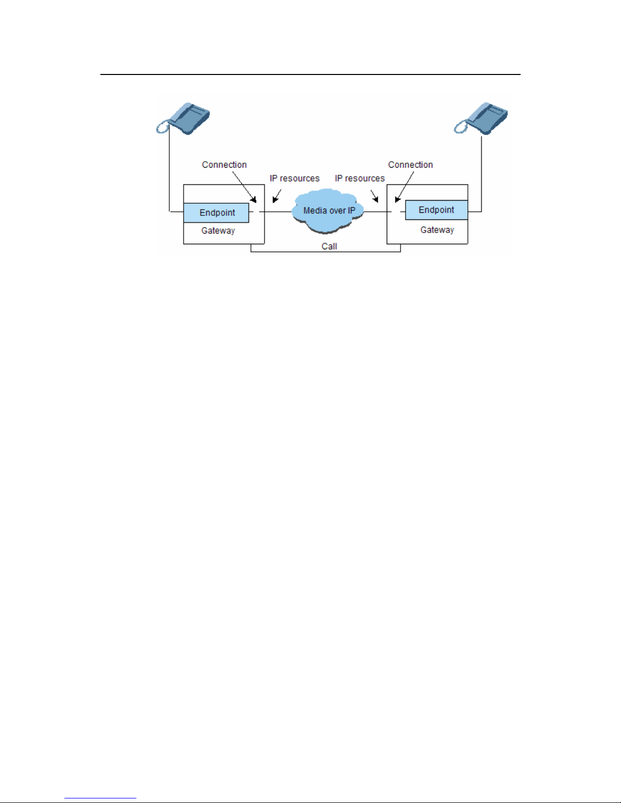
Connections are grouped by call. One call can include one or more connections. The
setup of connections and calls are initiated by of one or more MGCs.
Figure 5-3 shows the relations among endpoints, connections, calls, and gateways.
Page 29
Technical Manual
U-SYS MRS6100 Media Resource Server Chapter 5 MGCP and SIP
Huawei Technologies Proprietary
5-4
Figure 5-3 Relations among endpoints, connections, calls, and gateways
When the two gateways are managed by the same CA, the connection can be set up
through the following steps:
1) The CA asks the first gateway to create a connection on the first endpoint. The
gateway allocates resources to that connection and responds to the command
through a session description. The session description contains the information
necessary for a third party to send the packets to the connection, such as IP
address, UDP port, and packing parameters.
2) The CA then asks the second gateway to create a connection on the second
endpoint. The command carries the session description provided by the first
gateway. The gateway allocates resources to this connection and responds to
the command through a session description.
3) The CA provides the second session description to the first endpoint by using the
command for modifying connections. Once this process is complete, the two
endpoints can communicate with each other.
VI. Connection identifier
The gateway creates the connection. It assigns a unique identifier for the connection
on the local end. The connection identifier is a hexadecimal character string.
VII. Call identifier
Calls are identified by unique identifiers. The identifiers are created by the MGC. Call
identifiers can be considered as unstructured character strings. When an MGC builds
several connections for the same call, the connections must be associated with the
same call.
VIII. Naming CA and other entities
In the MGCP, the CAs are identified by domain names. To enhance the system
reliability, the MGCP can have a redundant CA. These CAs share the same domain
Page 30

Technical Manual
U-SYS MRS6100 Media Resource Server Chapter 5 MGCP and SIP
Huawei Technologies Proprietary
5-5
name but have different network addresses, such as IP addresses. Typically, the
gateway identifies a CA through its domain name. For lower-layer operations, the
gateway obtains the CA network addresses list from the domain name server (DNS),
and then uses an appropriate network address to communicate with the CA. The
redundancy mechanism is very helpful to enhance the reliability of the MRS6100.
Other entities, such as gateways and information servers, are also identified by their
domain names. Also, these entities can use the redundancy design to enhance the
reliability of the system. The CAs and gateways identify these entities through their
domain names.
With the domain names, you do not need to identify these entities using their network
addresses. The domain names are relatively stable while the network addresses can
be easily changed. For example, if an entity is moved to a different local access
network (LAN), the IP address of the entity will be changed. But you can keep using
the same domain name. The domain name lifetime ensures that other entities can
obtain the new IP addresses by updating the domain name information.
In the MGCP, CAs and other entities are represented by e-mail addresses.
For example:
[email protected] represents the CA in the example network
[email protected] represents the busy signal in the 12# information
server in the example network
IX. Events, signals, and packages
Events and signals are essential to the MGCP. The CA may ask to be notified about
certain events that occur at an endpoint, such as offhook, onhook, flash-hook, or
dialing. The CA may request certain signals to be applied to an endpoint, such as dial
tone, ring back tone, or busy tone.
Events and signals are integrated into packages. Each package is supported by a
specific endpoint.
An event is named in the following format:
Package name/event name
In the name, the package name is optional because each type of endpoint has a
related default package. If the package name is not included in the name, the default
package name is used.
The symbol @ with the event connection can be added after the event name. you can
also use the event range and a wildcard to indicate an event name. the wildcard *
represents “all” while the wildcard $ represents “current or any”.
Each signal has an associated signal type, such as on/off (OO), timeout (TO), and
brief (BR).
Table 5-1 lists some basic packages.
Page 31

Technical Manual
U-SYS MRS6100 Media Resource Server Chapter 5 MGCP and SIP
Huawei Technologies Proprietary
5-6
Table 5-1 Basic packages
Package Package ID
General media package
G
DTMF package
D
MF package
M
Trunk package
T
Line package
L
Handset emulation package
H
RTP package
R
Network access server package
N
Announcement server package
A
Script package
Script
Table 5-2 lists some valid event names.
Table 5-2 Event names
Event name Meaning
l/hd
Offhook event in the line packages
l/hu Onhook event in the line packages
l/dl Dial tone event in the line packages
l/hf
Flash-hook event in the line packages
l/aw
Answer tone event in the line packages
l/bz
Busy tone event in the line packages
l/wt
Call waiting tone event in the line packages
l/rg
Ringing event in the line packages
l/sl
Staccato dial tone event in the line packages
M/0
Digit 0 in the MF packages
M/[0-9]
Digits 0–9 in the MF packages
fh
Flash-hook event in the analog line default packages
G/rt@0A3F58
Ring back tone event in the general media packages on
connection 0A3F58
G/mt
Modem detected event in the general media packages
G/ft
Fax tone detected event in the general media packages
Page 32

Technical Manual
U-SYS MRS6100 Media Resource Server Chapter 5 MGCP and SIP
Huawei Technologies Proprietary
5-7
Event name Meaning
G/ld
Long-term connection event in the general media packages. If
a connection lasts for more than an hour, this event will be
detected.
[0-9*#A-D]
All digits and letters in the DTMF packages
T/$
All events in the trunk packages
R/qa@*
Quality alert event in the RTP packages in all connections
R/rt@$
Ring back tone event in the RTP packages on current
connection
X. Digit map
The CA may request the gateway to collect the dialed digits. For example, the MRS
collects the dialed number or the credit card number. In this case, the CA loads a digit
map to the gateway. Like a numbering plan, the digit map collects all the numbers,
and then sends the digits in a message. This helps to save the network resources.
This digit map is expressed using a strict syntax. It is composed of a list of digits and
letters. If collected dial sequence matches one of the defined strings, it indicates
necessary digits have been collected. What are supported in the definition of digit
strings include the digits from 0 to 9, the letters from A to D, the pound sign (#), the
asterisk sign (*), the letters T and x, and the dot sign (.). The digit strings separated by
| are alternative number schemes. The brackets ([]) indicates any of them. The
asterisk sign (*) indicates the digits are reported one by one if * is dialed. The letter T
indicates the timer is detected timeout. The letter x indicates any digit. The dot sign (.)
indicates any number of letters, including zero number of letters, can appear before it.
The pound sign (#) indicates to report the digits immediately.
For example, we can dial the following numbers using a phone.
Table 5-3 Digit map
0
Local call operator
00
Toll call operator
xxxx
Local area code
8xxxxxxx
Local call number
xxxxxxx#
Shortcut to local number at other corporate sites
*xx
Starts services
91xxxxxxxxxx Toll call number
9011 + up to 15 digits
International toll call number
Page 33

Technical Manual
U-SYS MRS6100 Media Resource Server Chapter 5 MGCP and SIP
Huawei Technologies Proprietary
5-8
The dial plan described above results in the following digit map:
(0T| 00T|[1-7]xxx|8xxxxxxx|xxxxxxx#|*xx|91xxxxxxxxxx|9011x.T)
5.2.3 Protocol Stack
MGCP is a both a definition of commands and a definition of signaling. By using
MGCP commands, media gateway controller (MGC) equipment can control
MRS6100. The commands and signals of MGCP are defined as IP packets, which
allow MGCP to be independent of the lower-layer bearer system. Through MGCP, a
call agent can run on a universal network computer platform.
Figure 5-4 shows the
structure of the MGCP protocol stack.
MAC
IP
UDP
MGCP
Figure 5-4 MGCP protocol stack
MGCP messages are transmitted over UDP/IP. The transport layer protocol is UDP
and the network layer protocol is IP.
5.2.4 Message Type
I. Command
Table 5-4 gives the names and corresponding meanings of MGCP commands, which
include connection processing and endpoint processing commands. There are nine
commands defined in this protocol.
Table 5-4 MGCP commands
Serial
No.
Command
name
Code Description
1
EndpointConfig
uration
EPCF
From MGC to MRS, used to show the
encoding feature of an endpoint circuit in the
gateway.
Page 34

Technical Manual
U-SYS MRS6100 Media Resource Server
Chapter 5 MGCP and SIP
Huawei Technologies Proprietary
5-9
Serial
No.
Command
name
Code Description
2
CreateConnecti
on
CRCX
From MGC to MRS, used by the call agent to
associate an endpoint with a specified IP
address and UDP port. Apart from that, a
CreateConnection command is also sent to
the remote endpoint, which is required to
create the connection between the two
endpoints.
3
ModifyConnecti
on
MDCX
From MGC to MRS, used to modify
parameters of established connections.
4
DeleteConnecti
on
DLCX
From MGC to MRS and MRS to MGC, used
to delete an existing connection.
5
NotificationReq
uest
RQNT
Used to instruct the gateway to monitor
specific events on a specified endpoint. If it
happens, the call agent will be notified.
6
Notify
NTFY
From MRS to MGC, used by the gateway to
notify the call agent that a specific event
requested to monitor takes place.
7
AuditEndpoints AUEP
From MGC to MRS, used by the call agent to
audit the status of an endpoint or a group of
endpoints.
8
AuditConnectio
n
AUCX
From MGC to MRS, used by the call agent to
audit the status of a connection on an
endpoint.
9
RestartInProgre
ss
RSIP
From MRS to MGC, used by the gateway to
notify the call agent that the gateway, or a
group of endpoints managed by the gateway,
is out of service or in service.
II. Response
All MGCP commands require responses. The response carries a return code which is
an integer, which can be within one of the following ranges:
100–199: indicates a provisional response.
200–299: indicates a successful completion of the command.
400–499: indicates that a transient error occurs.
500–599: indicates that a permanent error occurs.
Whether to return response parameters depends on specific commands.
Table 5-5 gives response codes that have been defined.
Page 35

Technical Manual
U-SYS MRS6100 Media Resource Server
Chapter 5 MGCP and SIP
Huawei Technologies Proprietary
5-10
Table 5-5 MGCP response codes
Response
code
Meaning
100
The transaction is currently being processed. An actual completion
message will follow on later.
200 The requested transaction is already processed normally.
250 The connection is already deleted.
400 The transaction can not be processed due to a transient error.
401 The phone is already off hook.
402 The phone is already on hook.
403
The transaction can not be processed because the endpoint does
not have sufficient resources at this time.
404 Insufficient bandwidth at this time.
500
The transaction can not be processed because the endpoint is
unknown.
501
The transaction can not be processed, because the endpoint is not
ready.
502
The transaction can not be processed because the endpoint does
not have sufficient resources.
510
The transaction can not be processed because a protocol error is
detected.
511
The transaction can not be processed because the command
contains an unrecognized extension name.
512
The transaction can not be processed because the gateway is not
equipped to detect one of the requested events.
513
The transaction can not be processed because the gateway is not
equipped to generate one of the requested signals.
514
The transaction can not be processed because the gateway
cannot send the specified announcement.
515
The transaction is related with an incorrect connection identifier
(may be already deleted).
516 The transaction is related with an unknown call identifier.
517 Unsupported or invalid mode.
518 Unsupported or unknown package.
519 Endpoint does not have a digit map.
520
The transaction can not be processed because the endpoint is
being restarted.
521 Endpoint is already redirected to another call agent.
Page 36

Technical Manual
U-SYS MRS6100 Media Resource Server
Chapter 5 MGCP and SIP
Huawei Technologies Proprietary
5-11
Response
code
Meaning
522 No such event or signal.
523 Unknown action or invalid combination of actions.
524 Internal inconsistency in LocalConnectionOptions.
525 Unknown extension name in LocalConnectionOptions.
526 Insufficient bandwidth.
527 Missing RemoteConnectionDescriptor.
528 Incompatible protocol version.
529 Internal hardware failure.
530 CAS signaling protocol error.
531 Trunk group failure (equipment failure for example).
5.2.5 Message Structure
I. Commands
1) Command format
Figure 5-5 shows the format of an MGCP command, which consists of a command
line and a group of parameter lines. A line feed character distinguishes the command
line and each parameter line.
Command name Transaction ID Point
Parameter name: value
:
…
Protocol Version
MML
Parameter line
Parameter name: value
Figure 5-5 Structure of MGCP command
2) Command parameters
z ResponseAck (K)
The response acknowledgement attribute indicates the identifiers of transactions that
have received the response command. It contains a comma-separated list of
confirmed transaction ID ranges, for example, K: 6234–6255, 6257, 19030–19044.
z BearerInformation (B)
Page 37

Technical Manual
U-SYS MRS6100 Media Resource Server
Chapter 5 MGCP and SIP
Huawei Technologies Proprietary
5-12
It refers to the bearer attribute. At present, only one attribute, namely “encoding” (the
code is “e”), is defined. Its values can be set to “A” which represents A-law and “µ”
which represents µ-law. For example, a BearerInformation code is B: e:mu.
z Call-ID (C)
Call-ID is a globally unique parameter that identifies the call (or session) to which this
connection belongs. Connections that belong to the same call share the same Call-ID.
The Call-ID can be used to identify calls for reporting and accounting purposes.
Call-ID identifies calls, which is a hexadecimal string of 32 characters at the
maximum.
z ConnectionId (I)
The ConnectionId parameter is a hexadecimal string of 32 characters at the
maximum.
z NotifiedEntity (N)
NotifiedEntity specifies where the notifications will be sent. If this parameter is absent,
the notifications will be sent to the originator of the NotificationRequest.
z RequestIdentifier (X)
RequestIdentifier is used to correlate this request with the notifications that it triggers.
RequestIdentifier is a hexadecimal string of 32 characters at the maximum.
z LocalConnectionOptions (L)
The local connection options describe the optional parameters that the call agent
recommends to the gateway. The parameters include: the packing period in
milliseconds (encoded as the keyword “p”), the preferred type of compression
algorithm (encoded as the keyword “a”), the bandwidth in kilobits per second
(encoded as the keyword “b”), the echo cancellation parameter (encoded as the
keyword “e”), the gain control parameter (encoded as the keyword “gc”), the silence
suppression parameter (encoded as the keyword “s”), the type of service parameter
(encoded as the keyword “t”), the resource reservation parameter (encoded as the
keyword “r”), the encryption key (encoded as the keyword “k”), and the type of
network (encoded as the keyword “nt”). All these parameters are optional. In the case
of multiple parameter values, commas are used for separation, for example:
L: p:10, a:PCMU
L: p:10, a:G726-32
L: p:10-20, b:64
L: b:32-64, e:off
z Connection Mode (M)
Table 5-6 gives connection modes and corresponding meanings.
Page 38

Technical Manual
U-SYS MRS6100 Media Resource Server
Chapter 5 MGCP and SIP
Huawei Technologies Proprietary
5-13
Table 5-6 Connection modes and meanings
Connection mode Meaning
sendonly The gateway only sends packets.
recvonly
The gateway only receives packets.
sendrecv The gateway sends and receives packets.
confrnce
The gateway places the connection in the conference
mode.
inactive The gateway neither sends nor receives packets.
loopback The gateway places the circuit in the loopback mode.
conttest The gateway places the circuit in the test mode.
netwloop
The gateway places the connection in the network
loopback mode.
netwtest
The gateway places the connection in the network
continuity test mode.
data
The gateway uses the circuit for network access for
data.
z RequestedEvents (R)
The RequestedEvents parameter provides a list of events that have been requested.
Each event can be restricted by a requested action, or by a list of actions. The actions,
when specified, are encoded as a list of keywords, enclosed in parenthesis and
separated by commas.
Table 5-7 lists the codes for various actions.
Table 5-7 Action codes
Code Action
N
Notify immediately
A
Accumulate
D Treat according to digit map
S Swap
I Ignore
K Keep signal(s) active
E Embedded notification request
When no action is specified, the default action is to notify the event. In this case, ft
equals to Ft (N). Events that are not listed are ignored.
Page 39

Technical Manual
U-SYS MRS6100 Media Resource Server
Chapter 5 MGCP and SIP
Huawei Technologies Proprietary
5-14
The digit-map action can only be specified for the digits, letters and inter-digit timers in
the MF and DTMF packets, or in other packages that need to define the encoding of
digits and timers.
The requested list is encoded on a single line, with event/action groups separated by
commas. The following is an example of RequestedEvents encoding.
R: hu(N), hf(S,N)
R: hu(N), [0-9#T](D)
z SignalRequests (S)
The SignalRequests parameter provides the name of the signals that have been
requested.
Several signals, such as announcement or ADSI display, can be qualified by
additional parameters:
the name and parameters of the announcement
the string that must be displayed
These parameters are encoded as a set of UTF8 character strings, separated by
commas and enclosed within parenthesis, as in:
S: adsi("123456 Francois Gerard")
S: ann(no-such-number, 1234567)
When several signals are requested, their codes are separated by commas, for
example:
S: asdi(123456 Your friend), rg
z ObservedEvents (O)
The ObservedEvents parameter provides a list of events that have been observed.
The following are examples of observed actions.
O: L/hu
O: 8295555T
O: 8,2,9,5,5,L/hf,5,5,T
O: L/hf, L/hf, L/hu
z ConnectionParameters (P)
Connection parameters are encoded as a string of type and value pairs, where the
type is either a letter identifier of the parameter or an extension type, and the value is
decimal integer. Types are separated from value by an equal sign (=). Parameters are
encoded from each other by a comma.
Table 5-8 shows the connection parameter types.
Page 40

Technical Manual
U-SYS MRS6100 Media Resource Server
Chapter 5 MGCP and SIP
Huawei Technologies Proprietary
5-15
Table 5-8 Connection parameter types
Code Name Connection parameter value
PS Packets sent
The number of packets that are sent on the
connection
OS
Octets sent
The number of octets that are sent on the
connection
PR
Packets
received
The number of packets that are received on the
connection
OR Octets received
The number of octets that are received on the
connection
PL Packets lost
The number of packets that are not received on the
connection, as deduced from gaps in the sequence
number
JI Jitter
The average inter-packet arrival jitter, in
milliseconds, expressed as an integer number
LA Latency
Average latency, in milliseconds, expressed as an
integer number
Example
P: PS=1245, OS=62345, PR=0, OR=0, PL=0, JI=0, LA=48
z ReasonCode (E)
Reason codes are used by the gateway when it deletes a connection to inform the call
agent about the reason for deleting the connection. They may also be used in a
RestartInProgress command to inform the gateway of the reason of the restart. The
reason code is an integer.
Table 5-9 lists the defined values.
Table 5-9 Command reason codes
Reason code Description
000
The endpoint is in a nominal status. (This code is used only
in response to audit requests.)
900 The endpoint is malfunctioning
901 The endpoint is taken out of service.
902 Lower-layer connection failed.
Reason codes are three-digit numeric values. The reason code is optionally followed
by a white space and commentary, for example:
900 Endpoint malfuctioning
z SpecificEndpointId (Z)
Page 41

Technical Manual
U-SYS MRS6100 Media Resource Server
Chapter 5 MGCP and SIP
Huawei Technologies Proprietary
5-16
The endpoint ID specified by the gateway is returned in a CreateConnection
response. The SpecificEndpointId is an optional parameter that identifies the
responding endpoint. It can be used when the EndpointId parameter uses any of
wildcard name. When a SpecificEndpointId is returned, the call agent must use it as
the EndpointId value in successive commands referring to this call.
z RequestedInfo (F)
When a non-wildcard EndpointId is specified, the (possibly empty) RequestedInfo
parameter describes the information that is requested for the EndpointId specified.
The following endpoint information can be audited with this command:
RequestedEvents, DigitMap, SignalRequests, RequestIdentifier, NotifiedEntity,
ConnectionIdentifiers, DetectEvents, ObservedEvents, EventStates, RestartReason,
RestartDelay, ReasonCode and Capabilities
The RequestedInfo parameter contains a comma separated list of parameter codes.
For example, if one wants to audit the value of the NotifiedEntity, RequestIdentifier,
RequestedEvents, SiganalRequests, DigitMap, QuarantineHandling, DetectEvents,
and Capabilities parameters, the value of the RequestedInfo parameter will be:
F:N,X,R,S,D,Q,T,A
z QuarantineHandling (Q)
The QuarantineHandling parameter specifies the handling of quarantine events, that
is, events that have been detected by the gateway before the arrival of the
NotificationRequest command, but have not yet been notified to the call agent. The
parameter provides a set of handling options:
z Whether the quarantined events must be processed or discarded. (The default is
to process them.)
z Whether the gateway is expected to generate at most one notification (step by
step), or multiple notifications (loop), in response to the request. (The default is
exactly one.)
Example
Q:loop
Q:process
Q:discard,loop
z DetectEvents (T)
The list of events that are currently detected in the quarantine mode. The DetectEvent
parameter is encoded as a comma separated list of events.
Example
T: hu,hd,hf,[0-9#*]
z RestartMethod (RM)
Page 42

Technical Manual
U-SYS MRS6100 Media Resource Server
Chapter 5 MGCP and SIP
Huawei Technologies Proprietary
5-17
The RestartMethod parameter specifies the type of restart, encoded as one of the
following keywords:
graceful: A “graceful” restart method indicates that the specified endpoints will be
taken out of service after the specified delay. The established connections are not yet
affected, but the call agent should refrain to establish new connections, and should try
to gracefully tear down the existing connections.
forced: A “forced” restart method indicates that the specified endpoints are taken
abruptly out of service. The established connections, if any, are lost.
restart: A “restart” method indicates that service will be restored on the endpoints after
the specified restart delay. There are no connections that are currently established on
the endpoints.
disconnected: A “disconnected” method indicates that the endpoint has become
disconnected and is now trying to establish connectivity. The restart delay specifies
the number of seconds the endpoint has been disconnected. Established connections
are not affected.
cancel-graceful: A “cancel-graceful” method indicates that a gateway is canceling a
previously issued “graceful” restart command.
Example
RM:restart
z RestartDelay (RD)
The restart delay parameter is expressed as a number of seconds. If the number is
absent, the delay value is considered null.
In the case of the “graceful” method, a null delay indicates that the call agent should
simply wait for the natural termination of the existing connections, without establishing
new connections. The restart delay is always considered null in the case of the
“forced” method. A restart delay of null for the “restart” method indicates that service
has already been restored. This will typically occur after gateway startup/reboot.
z EventStates (ES)
The EventStates parameter is encoded as a comma separated list of events.
Example
E: hu
z Capabilities (A)
The Capabilities parameters inform the call agent about capabilities of endpoints
when they are audited. The encoding of capabilities is based on the
LocalConnectionOptions encoding for the parameters that are common to both. The
parameters used are Event Packages (v), Modes (m), a list of supported codec (*),
type of network (nt), and so on.
Page 43

Technical Manual
U-SYS MRS6100 Media Resource Server
Chapter 5 MGCP and SIP
Huawei Technologies Proprietary
5-18
In addition, capabilities can also contain a list of supported packages and a list of
supported modes.
z RemoteConnectionDescriptor (RC)
The RemoteConnectionDescriptor includes the same fields as in the
LocalConnectionDescriptor, such as IP address, UDP port and packetization
parameters. For the CreateConnection command, this parameter may have a null
value when the information for the remote end is not known yet. This occurs because
the entity that builds a connection starts by sending a CreateConnection to one of
the two gateways involved in it. For the first CreateConnection issued, there is no
information available about the other side of the connection. This information may be
provided in SDP packets later through a ModifyConnection call.
z LocalConnectionDescriptor (LC)
The LocalConnectionDescriptor is a session description that contains information
about IP address and port number suitable for the local connection, as defined in SDP.
3) Command expressions
What are within the parenthesis preceded by the command name are input
parameters. Those enclosed by brackets are optional.
z EndpointConfiguration
EPCF (EndpointId, BearerInformation)
z NotificationRequest
RQNT
(EndpointId,[NotifiedEntity,][RequestedEvents,]RequestIdentifier,[DigitMap,][SignalR
equests,][QuarantineHandling,][DetectEvents,][encapsulated
EndpointConfiguration])
z Notify
NTFY (EndpointId,[NotifiedEntity,]RequestIdentifier,ObservedEvents)
z CreateConnection
CRCX
(Call-ID,EndpointId,[NotifiedEntity,]LocalConnectionOptions,]Mode,[RemoteConnecti
onDescriptor,][Encapsulated NotificationRequest,][Encapsulated
EndpointConfiguration])
z ModifyConnection
MDCX
(Call-ID,EndpointId,ConnectionId,[NotifiedEntity,][LocalConnectionOptions,][Mode,][
RemoteConnectionDescriptor,][Encapsulated NotificationRequest,][Encapsulated
EndpointConfiguration])
z DeleteConnection
DeleteConnection from the call agent:
Page 44

Technical Manual
U-SYS MRS6100 Media Resource Server
Chapter 5 MGCP and SIP
Huawei Technologies Proprietary
5-19
DLCX (Call-ID,EndpointId,ConnectionId,[Encapsulated
NotificationRequest,][Encapsulated EndpointConfiguration])
DeleteConnection from the VoIP gateway:
DLCX (Call-ID,EndpointId,ConnectionId,Reason-code,Connection-parameters)
DeleteConnection from the call agent to delete multiple connections:
DLCX (Call-ID,EndpointId)
z AuditEndpoint
AUEP (EndpointId,RequestedInfo)
z AuditConnection
AUCX (EndpointId,ConnectionId,RequestedInfo)
z RestartInProgress
RSIP (EndpointId,RestartMethod,[RestartDelay,][Reason-code])
4) Command example
The following is an MGCP command encoding example.
CRCX 693585490 ms/cnf/1@mrs6100 MGCP 1.0
C:a265
L:a:PCMA,P:20
M:sendrecv
v=0
c=IN IP4 182.20.40.4
m=audio 30002 RTP/AVP 8
The 1
st
line: The CreateConnection command. The transaction identifier is
693585490 and it is used to correlate this command with the responses that it triggers.
It indicates to create a connection between MGC and the first port of the MRS6100
whose domain name is mrs6100 and the interface name is ms/cnf. The protocol
version of MGCP is 1.0.
The 2
nd
line: The call identifier is a265.
The 3
rd
line: The local connection options. The call agent recommends to the MRS
that the compression algorithm is PCMA and the encapsulation delay is 20
milliseconds.
The 4
th
line: The connection mode is sendrecv, that is, both sending and receiving
packets are allowed.
The 5
th
line: Null, indicating what is preceded is an SDP session description.
The 6
th
line: The SDP protocol version is 0. It is the local connection descriptor at this
time.
Page 45

Technical Manual
U-SYS MRS6100 Media Resource Server
Chapter 5 MGCP and SIP
Huawei Technologies Proprietary
5-20
The 7
th
line: c in the response identifies the connection information. IN refers to
network type in the form of a text string. The currently defined IN is Internet. IP4
indicates the type of connection address is IP4. 182.20.40.4 represents the network
address of the remote gateway of MRS that has a connection with the MGC.
The 8
th
line: Media description. audio indicates the type of media is audio. (audio is
used for audio connections, and nas is used for data access.) 30002 is the number of
transport layer port to which media streams are transmitted. RTP/AVP is the transport
layer protocol. Its value is associated with the type of address in the c line. For IP4, a
great number of media service streams are transferred over RTP/UDP. There are two
classes of protocols defined: RTP/AVP, audio/video application document,
transported over UDP; Udp, the DUP protocol. At this time, the mapping relation from
RTP payload type to encoding is that 8 corresponds to the media encoding format
PCMA.
II. Responses
1) Response format
Similar to the format of MGCP commands, the response format is composed of a
response line followed by a group of optional parameter lines. The response line
consists of the response code, transaction identifier and an optional commentary that
is separated by a space, as shown in
Figure 5-6. The response code is a three-digit
numeric value, indicating the execution status of the command.
Response code Transaction ID Comment (optional)
Parameter name: value
…
MML
Parameter line
Parameter name: value
Figure 5-6 Structure of MGCP response
2) Response parameters
The response parameter lines are optional and depend on the specific commands.
For more information, refer to the section “Command parameters”, earlier in this
chapter.
3) Response expressions
What are within the parenthesis preceded by the command name are response
parameter values. Those enclosed by brackets are optional.
z EndpointConfiguration
EPCF (ReturnCode)
z NotificationRequest
Page 46

Technical Manual
U-SYS MRS6100 Media Resource Server
Chapter 5 MGCP and SIP
Huawei Technologies Proprietary
5-21
RQNT (ReturnCode)
z Notify
NTFY (ReturnCode)
z CreateConnection
CRCX (ReturnCode,ConnectionId,[SpecificEndpointId,][LocalConnectionDescriptor])
z ModifyConnection
MDCX (ReturnCode,[LocalConnectionDescriptor])
z DeleteConnection
DeleteConnection from the call agent:
DLCX (ReturnCode,Connection-parameters)
DeleteConnection from the VoIP gateway:
DLCX (ReturnCode)
DeleteConnection from the call agent to delete multiple connections:
DLCX (ReturnCode)
z AuditEndpoint
AUEP
(ReturnCode,EndpointIdList|{[RequestedEvents,][DigitMap,][SignalRequests,][Requ
estIdentifier,][NotifiedEntity,][ConnectionIdentifiers,][DetectEvents,][ObservedEvents,
][EventStates,][BearerInformation,][RestartReason,][RestartDelay,][ReasonCode,][C
apabilities]})
z AuditConnection
AUCX
(ReturnCode,[Call-ID,][NotifiedEntity,][LocalConnectionOptions,][Mode,][RemoteCon
nectionDescriptor,][LocalConnectionDescriptor,][ConnectionParameters])
z RestartInProgress
RSIP (ReturnCode,[NotifiedEntity])
4) Response example
The following is an example of connection response.
200 693585490 CRCX OK
I:1607901
v=0
c=IN IP4 182.20.50.101
m=audio 10000 RTP/AVP 8 0 18 4
a=ptime:20
Page 47

Technical Manual
U-SYS MRS6100 Media Resource Server
Chapter 5 MGCP and SIP
Huawei Technologies Proprietary
5-22
The 1
st
line: 200 indicates the successful receipt of the command. 693585490 is a
transaction identifier which is the same as the transaction identifier contained in the
CreateConnection command that triggers this response. CRCX OK is a
commentary.
The 2
nd
line: The connection identifier is 1607901.
The 3
rd
line: Null, indicating what is preceded is an SDP session description.
The 4
th
line: The SDP protocol version is 0. It is the local connection descriptor at this
time.
The 5
th
line: c in the response identifies the connection information. IN refers to
network type in the form of a text string. The currently defined IN is Internet. IP4
indicates the type of connection address is IP4. 182.20.50.101 represents the local
network address of MRS6100.
The 6
th
line: Media description. audio indicates that the type of media is audio. (audio
is used for audio connections, and nas used for data access.) 10000 is the number of
transport layer port to which media streams are transmitted. RTP/AVP is the transport
layer protocol. Its value is associated with the type of address in the c line. For IP4, a
great number of media service streams are transferred over RTP/UDP. There are two
classes of protocols defined: RTP/AVP, audio/video application document,
transported over UDP; Udp, the DUP protocol. For audio and video signals, 8 0
represents the type of media payload defined in the RTP audio/video application
document. It means that all the formats carried in the session might be used, but the
first one is the default format for the session. At this time, the mapping relation from
RTP payload type to encoding is that 34 corresponds to the media encoding format
H263 .8 corresponds to the media encoding format PCMA. 0 corresponds to the
media encoding format PCMU. 18 corresponds to the media encoding format G.729.
4 corresponds to the media encoding format G.723.
The 7
th
line: Attribute. Attribute is the basic method for SDP extension. It can be
defined as session-level attribute or media-level attribute. There are two forms of
attributes:
a=<flag>, as feature attribute. It is a binary attribute, indicating the session has this
nature. For example, a=recvonly indicates the feature is “receive only”.
a=<attribute>:<value>, as numeric value attribute. For example, a=ptime:20 indicates
the domain name of the media attribute is ptime and the value of the media attribute is
20.
5.2.6 Call Flow
I. MRS6100 registration flow
If the control protocol is MGCP, MRS6100 must register to MGC before it can proceed
to subsequent procedures. The registration flow of MRS6100 is shown in
Figure 5-7.
Page 48

Technical Manual
U-SYS MRS6100 Media Resource Server
Chapter 5 MGCP and SIP
Huawei Technologies Proprietary
5-23
MGCMRS6100
RSIP
RSIP_RSP
Figure 5-7 MRS6100 registration flow
1) Event 1: MRS sends an RSIP command to MGC, reporting the completion of a
load or restart and requesting to register to MGC.
An example of RSIP encoding:
RSIP 836 *@mrs6100 MGCP 1.0
RM:restart
The 1st line: the RestartInProgress command. The transaction identifier is 836, used
to correlate this command with responses that it triggers. The field *@mrs6100
indicates the restart of all endpoints with the domain name mrs6100. The MGCP
version is V1.0.
The 2nd line: The restart mode is restart. It indicates that the service will be restored
on endpoints of the media gateway (MG) after the specified restart delay. There are
no connections that are currently established on endpoints of MG.
2) Event 2: MGC sends a response to the registration request sent by MRS. The
following are RestartInProgress response examples.
Example 1:
200 836 OK
z The field 200 indicates the successful receipt of the command. The field 836 is a
transaction identifier, the same as the transaction identifier contained in the
command that triggers this response. OK is a comment. It indicates that MG
receives the response and the registration succeeds.
Example 2:
500 836 The endpoint is unknown
The field 500 indicates that the transaction cannot be carried out, because the
endpoint is unknown. The field 836 is a transaction identifier, the same as the
transaction identifier contained in the command that triggers this response. The
endpoint is unknown is a comment. It indicates that MG receives the response and
the registration fails.
II. MRS6100 announcement playing flow
Figure 5-8 shows the flow of MRS6100 announcement playing and calling under the
control of one MGC.
In the following example, it is assumed that:
Page 49

Technical Manual
U-SYS MRS6100 Media Resource Server
Chapter 5 MGCP and SIP
Huawei Technologies Proprietary
5-24
z The domain name of Endpoint1 is IDms/cnf/[email protected].
z The IP address of MRS is 182.20.50.101.
MRS6100MGC
CRCX
CRCX ACK
RQNT(pa,pc)
NTFY
(oc,of,digit)
NTFY ACK
RQNT ACK
DLCX
DLCX ACK
(1)
(2)
(3)
(4)
Figure 5-8 Flow of MRS6100 announcement playing and digit collection
1) Event 1: MGC specifies MRS6100 to send a CRCX command to the Endpoint1,
requesting to establish a connection.
z CRCX encoding
CRCX 693585490 ms/cnf/[email protected] MGCP 1.0
C:a265
L:a:PCMA,P:20
M:sendrecv
v=0
c=IN IP4 182.20.40.4
m=audio 30002 RTP/AVP 8
The 1st line: the CreateConnection command. The transaction identifier is 693585490,
used to correlate this command with responses that it triggers.MGC establishes a
connection with the Endpoint1 of MRS6100. MRS6100's domain name is
mrs6100.com and interface name is ms/cnf. The MGCP version is V1.0.
Page 50

Technical Manual
U-SYS MRS6100 Media Resource Server
Chapter 5 MGCP and SIP
Huawei Technologies Proprietary
5-25
The 2nd line: The Call-ID is a265.
The 3rd line: the local connection options. The Call Agent suggests MRS to set the
compression algorithm to PCMA and set the encapsulation delay to 20 milliseconds.
The 4th line: The connection mode is sendrecv, that is, both sending and receiving of
data packets are allowed.
The 5th
line: Null, indicating that the following is the SDP session description.
The 6th line: The version of SDP protocol is 0. It is the local connection descriptor.
The 7th line: The field c identifies the connection information. IN refers to network
indicator in the form of a text string. The currently defined IN is Internet. IP4 indicates
that the connection address type is IP4. 182.20.40.4 represents the network address
of the MRS peer gateway that has a connection with MGC.
The 8th line: media description. The field audio refers to the media type. 30002 is the
No. of the transport layer port to which media streams are transmitted. RTP/AVP is
the transport layer protocol. The field 8 corresponds to the media coding/encoding
format PCMA.
z CRCX ACK encoding
200 693585490 OK
I:1607901
v=0
c=IN IP4 182.20.50.101
m=audio 10000 RTP/AVP 8 0 18 4
a=ptime:20
The field 200 indicates the successful receipt of the command. 693585490 is a
transaction identifier, the same as the transaction identifier contained in the command
that triggers this response. OK is a comment. It indicates that MG has received and is
processing the request. The field I is the connection identifier. MRS returns the
connection identifier to MGC after establishing a connection. In addition, MRS returns
the SDP session description, MRS port number and IP address.
2) Event 2: After establishing a connection, MGC sends the RQNT announcement
playing command to MRS.
z RQNT encoding
RQNT 170983909 ms/cnf/[email protected] MGCP 1.0
X:1e000424
R:A/of(N),A/oc
S:BAU/pa@0(an=HWF001000B?lang=chi iv=10 it=20)
Page 51

Technical Manual
U-SYS MRS6100 Media Resource Server
Chapter 5 MGCP and SIP
Huawei Technologies Proprietary
5-26
The 1st line: the OperationRequest command. The endpoint is ms/cnf/1, and the
domain name is mrs6100.com.
The 2nd line: The request identifier is 1e000424, used to correlate this request with
notifications that it triggers.
The 3rd line: Request events include the oc (operation complete) event and the of
(operation fail) event in packet A.
The 4th line: The signal tone is the pa (play announcement) event in packet BAU. The
voice is HWF001000B. The playing language is Chinese. The parameter it indicates
the announcement playing is carried out for 20 times. The parameter iv indicates that
the announcement playing interval is one second.
z RQNT_ACK encoding
200 170983909 OK
The field 200 indicates the successful receipt of the command. 170983909 is a
transaction identifier that is the same as the transaction identifier contained in the
command that triggers this response. OK is a comment. It indicates that MG has
received and is executing the request.
3) Event 3: After playing announcements, MRS sends the NTFY command to MGC
to notify it of the completion.
z NTFY encoding
NTFY 170983911 ms/cnf/[email protected] MGCP 1.0
X:1e000424
O:oc
The 1st line: the Notify command. The endpoint is ms/cnf/1, and the domain name is
mrs6100.com.
The 2nd line: The request identifier is 1e000424. The value is the same as the value
of the parameter contained in the RQNT command that triggers this notification. It is
used to correlate the RQNT command with the NTFY command.
The 3rd line: The oc event is detected.
z NTFY ACK encoding
200 170983911 OK
The field 200 indicates the successful receipt of the command. 170983911 is a
transaction identifier, the same as the transaction identifier contained in the command
that triggers this response. OK is a comment. It indicates that MG has received and is
executing the request.
4) Event 4: MGC sends a DLCX command to MRS, requesting to delete the
existing connection.
z DLCX encoding
DLCX 171000292 ms/cnf/[email protected] MGCP 1.0
Page 52

Technical Manual
U-SYS MRS6100 Media Resource Server
Chapter 5 MGCP and SIP
Huawei Technologies Proprietary
5-27
I:1607901
O:oc
Line 1: the DeleteConnection command. The endpoint is ms/cnf/1, and the domain
name is mrs6100.com.
The 2nd line: The connection identifier is 1607901.
z DLCX ACK encoding
250 171000292 OK
P:PS=300,OS=3000,PR=1000,OR=10000,PL=0,JI=0,LA=0
250 indicates the connection is deleted.171000292 is a transaction identifier. OK is a
comment. The 2nd line is the returned statistics information.
III. MRS6100 digit collection flow
Figure 5-9 shows the flow of MRS6100 announcement playing and calling under the
control of one MGC.
The connection establishing and deleting have the same flow with the announcement
playing. Here we only describe the digit collection flow.
MRS6100
MGC
RQNT(pc)
NTFY
(digit)
NTFY ACK
RQNT ACK
(1)
(2)
Figure 5-9 MRS6100 digit collection flow
1) Event 1: After establishing a connection, MGC sends the RQNT digit collection
command to MRS.
z RQNT encoding
RQNT 1709839323 ms/cnf/[email protected] MGCP 1.0
X:1e000425
R:D/[0-9*#T](N),of
D:( 0xxxxxxxxxx|*|x.# )
Line 1: It indicates the operation request command. The endpoint is ms/cnf/1, and the
domain name is mrs6100.com.
Page 53

Technical Manual
U-SYS MRS6100 Media Resource Server
Chapter 5 MGCP and SIP
Huawei Technologies Proprietary
5-28
Line 2: The request ID is 1e000425. The ID associates the request with the
notification.
Line 3: The request events are the digit collecting event under packet D and the
operation fail (of) event.
Line 4: It indicates the Digit Map. The MGC delivers the dial scheme to the gateway
where the Endpoint1 is located. 0xxxxxxxxxx represents an 11-digit number starting
with 0. The asterisk (*) indicates that if you dial *, the number is reported one by one.
x.# indicates if you dial any number and then #, the number is reported immediately.
z RQNT ACK response encoding
200 1709839323 OK
200 indicates that the command is correctly received.
170983909 is a transaction identifier. It is similar to the identifier for the command that
triggers the response.
OK is a comment. Here, it indicates that the gateway has received and is executing
the requested command.
z RQNT ACK encoding
200 1709839323 OK
200 indicates the successful receipt of the command.
170983909 is a transaction identifier which is similar to the identifier for the command
that triggers this response.
OK is a comment. It indicates that MG has received and is executing the request.
2) Event 2: After completing the digit collection, MRS sends a NTFY command to
MGC, to notify it of the received numbers.
z NTFY encoding
NTFY 170983911 ms/cnf/[email protected] MGCP 1.0
X:1e000425
O:1,2,3,4,5
The 1st line: the Notify command. The endpoint is ms/cnf/1, and the domain name is
mrs6100.com.
The 2nd line: The request identifier is 1e000424. The value is the same as the value
of the parameter contained in the RQNT command that triggers this notification. The
request identifier is used to correlate the RQNT command with the NTFY command.
The 3rd line: The number detected by MRS is 12345.
z NTFY ACK encoding
200 170983911 OK
The field 200 indicates the successful receipt of the command. 170983911 is a
transaction identifier which is the same as the transaction identifier contained in the
Page 54

Technical Manual
U-SYS MRS6100 Media Resource Server
Chapter 5 MGCP and SIP
Huawei Technologies Proprietary
5-29
command that triggers this response. OK is a comment. It indicates that MG has
received and is executing the request.
IV. MRS6100 conference flow
Figure 5-10 shows the call flow of an MRS6100 three-party conference under the
control of one MGC. The flow is the simplest one. There are some more complex
flows that are alike in principle. To focus on the description of MGCP, we do not
introduce other flows here. In the following example, it is assumed that:
z The Endpoint1 ID is ms/cnf/[email protected].
z The IP address of MCCU of MRS6100 is 182.20.50.101.
MRS6100MGC
CRCX
CRCX ACK
RQNT(pa)
NTFY
NTFY ACK
RQNT ACK
DLCX
DLCX ACK
(1)
(2)
(3)
CRCX ACK
CRCX ACK
CRCX
CRCX
(4)
(5)
(6)
Figure 5-10 MRS6100 conference flow
1) Event 1: MGC specifies MRS6100 to send a CRCX command to the Endpoint1,
requesting to establish a connection. The connection mode must be confrnce.
z CRCX encoding
CRCX 693585490 ms/cnf/[email protected] MGCP 1.0
C:a265
L:a:PCMA,P:20
M:confrnce
v=0
c=IN IP4 182.20.40.4
m=audio 30002 RTP/AVP 8
z CRCX ACK encoding
Page 55

Technical Manual
U-SYS MRS6100 Media Resource Server
Chapter 5 MGCP and SIP
Huawei Technologies Proprietary
5-30
200 693585490 OK
I:1607901
v=0
c=IN IP4 182.20.50.101
m=audio 10000 RTP/AVP 8 0 18 4
2) Event 2: MGC specifies MRS6100 to send a CRCX command to the same
Endpoint1, requesting to establish the second-party connection. The mode is not
specified. While selecting the confrnce or the sendrecv mode, participants can
both listen and speak. While selecting the sendonly or the recvonly mode,
participants can only speak or only listen. Other parameters can also be modified
according to the successive MDCX.
z CRCX encoding
CRCX 693585491 ms/cnf/[email protected] MGCP 1.0
C:a265
L:a:PCMA,P:20
M:confrnce
v=0
c=IN IP4 182.20.40.5
m=audio 30004 RTP/AVP 8
z CRCX ACK encoding
200 693585491 OK
I:1607902
v=0
c=IN IP4 182.20.50.101
m=audio 10002 RTP/AVP 8 0 18 4
3) Event 3: MGC specifies MRS6100 to send a CRCX command to the same
Endpoint1, requesting to establish the third-party connection. The mode is not
specified. While selecting the confrnce or the sendrecv mode, participants can
both listen and speak. While selecting the sendonly or the recvonly mode,
participants can only speak or only listen. Other parameters can also be modified
according to the successive MDCX. Then the three-party conference has been
established.
z CRCX encoding
Page 56

Technical Manual
U-SYS MRS6100 Media Resource Server
Chapter 5 MGCP and SIP
Huawei Technologies Proprietary
5-31
CRCX 693585492 ms/cnf/[email protected] MGCP 1.0
C:a265
L:a:PCMA,P:20
M:confrnce
v=0
c=IN IP4 182.20.40.5
m=audio 30006 RTP/AVP 8
z CRCX ACK encoding
200 693585492 OK
I:1607903
v=0
c=IN IP4 182.20.50.101
m=audio 10004 RTP/AVP 8 0 18 4
4) Event 4: After establishing a connection, MGC sends the RQNT announcement
playing command to MRS, to play announcements for the entire conference. If
the command contains a connection identifier, MRS will play announcements to
a specified party.
z RQNT encoding
RQNT 170983709 ms/cnf/[email protected] MGCP 1.0
X:1e000324
R:of, oc
S:BAU/pa(an=HWF001000B?lang=chi)
z RQNT ACK encoding
200 170983709 OK
5) Event 5: After the announcement playing is completed, MRS sends a NTFY
command to MGC, to notify it of the completion of the announcement playing for
the entire conference.
z NTFY encoding
NTFY 170983917 ms/cnf/[email protected] MGCP 1.0
X:1e000429
O:oc
z NTFY ACK encoding
200 170983917 OK
Page 57

Technical Manual
U-SYS MRS6100 Media Resource Server
Chapter 5 MGCP and SIP
Huawei Technologies Proprietary
5-32
6) Event 6: MGC sends a DLCX command to MRS, requesting to delete the entire
conference. If the command does not contain a connection identifier, it indicates
the entire conference is to be deleted. Or a specified party of the conference is to
be deleted.
z DLCX encoding
DLCX 171000299 ms/cnf/[email protected] MGCP 1.0
z DLCX ACK encoding
250 171000292 OK
P:PS=300,OS=3000,PR=1000,OR=10000,PL=0,JI=0,LA=0
5.3 SIP
5.3.1 Basic Concepts
Put forward and studied by the IETF, Session Initiation Protocol (SIP) is an
application-layer control protocol for multimedia communication over IP network,
which can be used for creating, modifying and terminating sessions with one or more
participants. These sessions include Internet multimedia conferences, Internet
telephone calls, distance learning, telemedicine, and similar applications.
Multimedia sessions refer to two-party or multiparty interactive multimedia
communication activities on the Internet. Participants in a session can communicate
through multicast or through a mesh of unicast relations. Alternatively, they can
communicate through a combination mode of these two.
SIP learns from design concepts of other Internet standards and protocols and follows
Internet principles including the concision, openness, compatibility and expandability,
with security issues taken into account. On the other hand, SIP comprehensively
provides support to traditional PSTN services including IN and ISDN services.
SIP invitations with session descriptions are used to create sessions, which allow
participants to agree on a set of compatible media types. The protocol supports user
mobility by sending proxy and redirecting requests to the user’s current location.
Users can also register their current locations. SIP is not tied to any particular
conference control protocol. It is also designed to be independent of the lower-layer
transport protocol, so SIP can be extended with additional functions.
Being an application-layer multimedia session protocol, SIP can be used to initiate
sessions, as well as inviting members to sessions that have been advertised and
established by other means. Sessions can be advertised using multicast protocols
such as Session Announcement Protocol (SAP), electronic mail, web pages or
Lightweight Directory Access Protocol (LDAP). SIP supports name mapping and
redirection services, allowing the implementation of ISDN and IN services. These
facilities also enable personal mobility, that is, the ability of end users to request and
Page 58

Technical Manual
U-SYS MRS6100 Media Resource Server
Chapter 5 MGCP and SIP
Huawei Technologies Proprietary
5-33
access subscribed telecommunication services on any terminal in any location at any
time.
SIP supports five signaling functions of multimedia communications:
z User location: determination of the end system to be used for communication.
z User capabilities: determination of the media and media parameters to be used.
z User availability: determination of the willingness of the callee to engage in
communications.
z Call setup: establishment of call parameters at both caller and callee, including
ringing to the callee.
z Call handling and control: including call redirection, call transfer; and call
termination.
SIP can initiate multiparty sessions using the Multipoint Control Unit (MCU), unicast
mesh, or multicast, supporting gateway functionality between PSTN and Internet
calls.
SIP can be used in conjunction with other signaling systems or protocols for call setup.
Implementation of SIP is designed with expandability to other protocols taken into
consideration. For example, SIP could be used to determine that the callee can be
reached through H.323 protocol, obtain the H.245 gateway and user address and
then use H.225.0 protocol to establish the call. In another example, SIP might be used
to determine that the callee is reachable through the PSTN and indicate the phone
number to be called, possibly suggesting an Internet-to-PSTN gateway to be used.
SIP does not offer conference control services such as floor control or voting and
does not prescribe how a conference is to be managed, but SIP can be used to
introduce conference control protocols. SIP does not reserve resources, but can
convey to the invited system the information necessary to do this.
5.3.2 Terms
I. Call
A call refers to a conference where participants are all invited by a common source. It
is identified by a globally unique call-ID.
For example, all participants invited by a common source in a conference form one
call. A point-to-point Internet telephony conversation is one of the simplest sessions
and maps into a single SIP call.
A call is generally established by the caller. However, it can also be established by a
third party who does not participate in the media communication, where the caller of
the session is not the same as the inviter of the session. For multicast conferences,
when a user is invited to one multicast session by several people at the same time,
each of these invitations is a unique call. In an MCU-based call-in conference, each
participant uses a separate call to invite himself to the MCU.
Page 59

Technical Manual
U-SYS MRS6100 Media Resource Server
Chapter 5 MGCP and SIP
Huawei Technologies Proprietary
5-34
II. Transaction
SIP is a client/server protocol. A SIP transaction occurs between a client and a server
and comprises all messages from the first request to the final response sent from the
server to the client.
A normal call consists of three transactions. Call initiation consists of two operation
requests, INVITE and ACK. The former requires a response. The latter is used for
acknowledging the reception of the final response, and need not to send back a
response. Call termination consists of one operation request, BYE.
III. SIP URL
SIP uniform resource locators (URLs) are used for addressing purposes. The SIP
URL syntax is defined according to the uniform resource ID (URI) guidelines specified
in RFC 2396. The user name field could be a telephone number to support addressing
of IP telephony gateway and achieve the interworking between IP calls and PSTN.
A SIP URL has the syntax:
SIP: User name: Password @ Host: Port: Transmission Parameters: User
parameters: Method parameters: TTL parameters: Server address parameters?
header name= header value.
SIP indicates that SIP is used for the communication to the specified end system.
User name is composed of any characters. Generally, it can be a phone number or a
user name as in E-mail address.
Host is either a domain name or an IPv4 address.
Port refers to the port number to which a request message is sent. The default port
number is 5060, the public SIP port number.
Password can be included in a SIP URL, which is not recommended for the sake of
security.
Transport parameter indicates the used transport protocol, TCP or UDP. The default
transport parameter is UDP.
A function of SIP URL is to allow the host to be an IP telephony gateway with a
telephone number as the username. Because BNF syntax cannot distinguish
telephone number from general username, User parameter is added to follow the
domain name. Two values are available for this field: IP and phone. When the field is
set to phone, the username is a telephone number and the corresponding end
system is an IP telephony gateway.
Method parameter refers to the method (operation) to be used.
Lifetime parameter indicates the life of UDP multicast data packets. This parameter
is valid only when the transport parameter is set to UDP and the server address
parameter is set to multicast address.
Page 60

Technical Manual
U-SYS MRS6100 Media Resource Server
Chapter 5 MGCP and SIP
Huawei Technologies Proprietary
5-35
Server address parameter indicates the address of the server communicating with
the user, which overwrites the address in the host field. It is usually a multicast
address.
Transport parameter, Lifetime parameter, Server address parameter, and
Method parameter are URL parameters used only in a redirect address, that is, the
Contact field which will be mentioned later.
The following are some SIP URL examples.
Sip: [email protected];
55500200 is a username. 182.20.1.112 is the IP address of an IP telephony gateway.
Sip: [email protected]:5061; User=phone;
55500200 is a username. 127.0.0.1 is the IP address of a host. 5061 is a port number
of the host. The user parameter is phone, indicating the username is a telephone
number.
Sip: [email protected]; method=REGISTER;
Alice is a username. registrar.com is the domain name of a host. Register is the
method parameter.
IV. User location
User location is based on registration. After a SIP user terminal is powered on, it starts
to register to a registrar. For that specific purpose, REGISTER request and
registration procedure are defined in SIP.
V. Location service
A location service is used by a SIP redirect or proxy server to obtain information about
a callee's possible location. Location services are offered by location servers.
Location servers may be co-located with a SIP server, but the manner in which a SIP
server requests location services is beyond the scope of this document.
VI. Proxy server
Proxy server is a logical network entity that acts as both a server and a client for the
purpose of forwarding requests or responses on behalf of other clients. Proxy server
may be in one of the three states: Stateless, Stateful and Call Stateful. It attempts to
forward requests to multiple addresses with a branch or cycle method.
Proxy server implements the functions of routing, authentication, charging monitoring,
call control and service provision.
VII. Redirect server
Redirect server is a server that accepts a SIP request, maps the address into zero or
several new addresses, and returns these addresses to the client. Then the client can
directly initiate requests to these new addresses again. Redirect server implements
Page 61
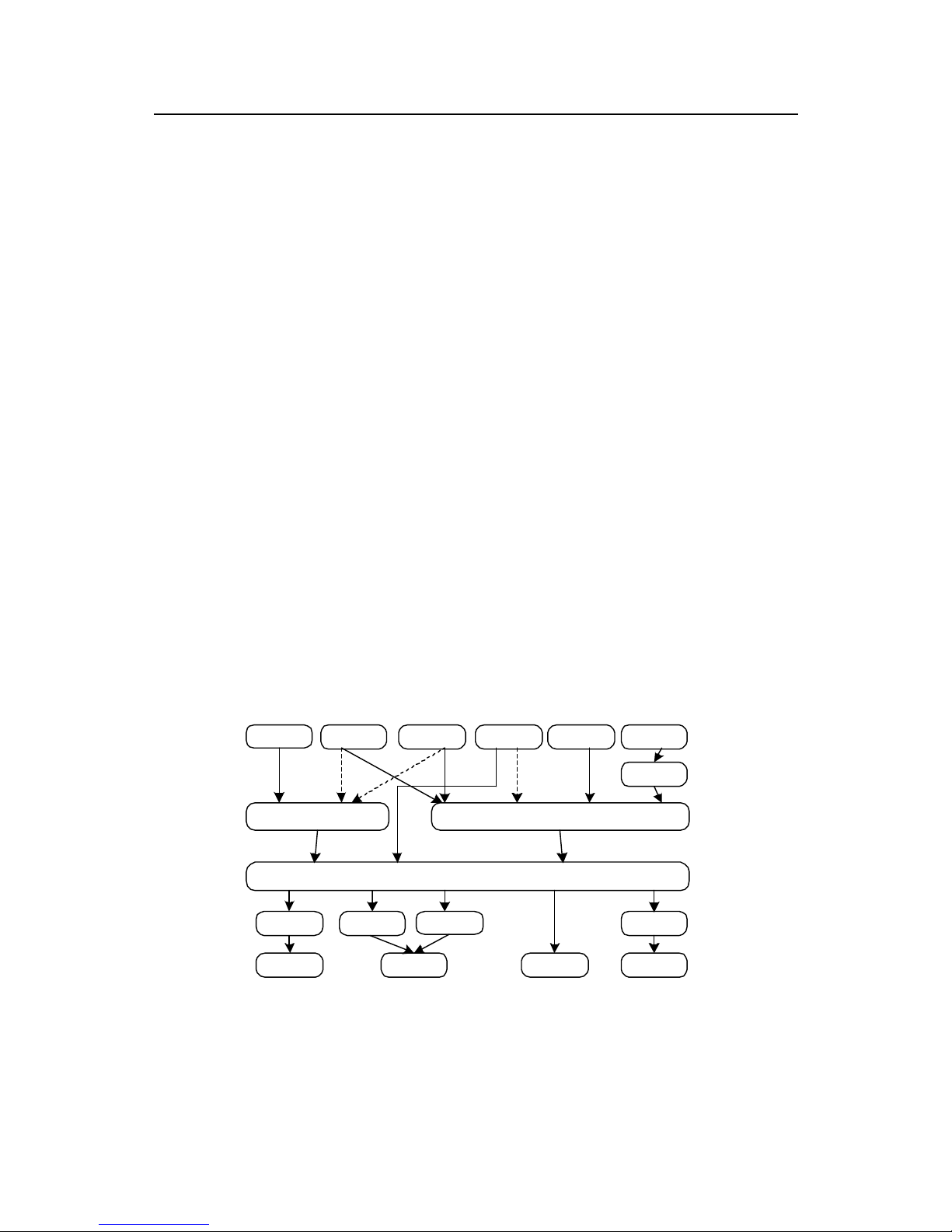
Technical Manual
U-SYS MRS6100 Media Resource Server
Chapter 5 MGCP and SIP
Huawei Technologies Proprietary
5-36
the routing function rather than receive or reject calls. Cooperating with a registration
process, it can support the mobility of SIP terminals.
VIII. Registrar
Register is a server that accepts REGISTER requests. A registrar is typically
co-located with a proxy or redirect server. Registrar needs to store the address
mapping relationship in REGISTER requests in a database for subsequent call
processes. Registrar can also offer location services.
IX. User Agent (UA)
UA is a logical entity that can initiates or receive SIP requests.
X. User Agent Client (UAC)
UAC is a client application that initiates the SIP request. For example, SIP Phone is
an application of UAC.
XI. User agent server (UAS)
UAS is a client application that receives the SIP request. For example, MRS6100 is
an application of UAS.
The distinguishing of UAC and UAS is based on one transaction.
5.3.3 Protocol Stack
Figure 5-11 shows the protocol stack structure of IETF multimedia data and control
architecture.
H.323 SIP RTSP RSVP RTCP H.263 etc.
RTP
TCP UDP
IP
PPP
Sonet
AAL3/4 AAL5
ATM Ethernet
PPP
V.34
Figure 5-11 Protocol stack structure of IETF multimedia data and control architecture
SIP is part of the overall IETF multimedia data and control architecture, cooperating
with other protocols such as:
Page 62

Technical Manual
U-SYS MRS6100 Media Resource Server
Chapter 5 MGCP and SIP
Huawei Technologies Proprietary
5-37
z RSVP (Resource ReServation Protocol) for reserving network resources
z RTP (Real-Time Transmit Protocol) for transmitting real-time data and providing
QoS feedback
z RTSP (Real-Time Stream Protocol) for controlling the transmission of media
streams in real time
z SAP (Session Announcement Protocol) for advertising multimedia sessions
through multicast
z SDP (Session Description Protocol) for describing multimedia sessions However,
the functionality and operation of SIP does not rely on any of these protocols
z Transport-layer support: SIP is borne over the IP network. The network-layer
protocol is IP and the transport-layer protocol is UDP
5.3.4 Message Type
SIP messages are encoded in text form. There are two types of messages, request
messages and response messages.
I. Request messages
Request messages are SIP messages sent from a client to a server, for invoking
particular operations. Request messages include INVITE, ACK, OPTIONS, BYE,
CANCEL and REGISTER messages. Functions of these messages are listed in
Table 5-10.
Table 5-10 Request messages
Request
messages
Message meanings
INVITE
The INVITE message indicates that the user is being invited to
participate in a session. The message body contains a
description of the session to which the callee is being invited.
For two-party calls, the caller indicates the type of media it is
able to receive as well as their parameters. A success response
must indicate in its message body which media the callee
hopes to receive and may indicate the media the callee is going
to send.
The callee can acknowledge the participating of the caller and
send the 200 (OK) response, according to the Call-ID or the
identifier in the session description.
ACK
The ACK request confirms that the client has received a final
response to an INVITE request. ACK is used only with INVITE
messages.
BYE
UAC uses BYE to indicate to the server that it hopes to release
the call.
CANCEL
The CANCEL request cancels a pending request, but does not
affect a completed request. (A request is considered completed
if the server has returned a final status response.)
Page 63

Technical Manual
U-SYS MRS6100 Media Resource Server
Chapter 5 MGCP and SIP
Huawei Technologies Proprietary
5-38
Request
messages
Message meanings
REGISTER
MG registers to MGC.
OPTIONS
The OPTIONS request is used to query servers about their
capabilities.
II. Response messages
Response messages are used to respond to request messages, indicating the
success or failure of calls. Different classes of response messages are distinguished
by status codes. The status-code is a 3-digit integer. The first digit defines the class of
response. The last two digits describe the response in detail.
Table 5-11 shows the
classification of response messages and their meanings.
Table 5-11 Response messages
Serial
No.
Status-Code Message functions
1xx
Informational
(provisional)
Indicating the request message has been received
and is being processed
100 Trying
180 Ringing
181 Call Is being forwarded
182 Queued
2xx
Success
The action is successfully received, understood, and
accepted.
200 OK
3xx
Redirection
Further action needs to be taken in order to complete
the request.
300
Multiple choices
301
Moved permanently
302
Moved temporarily
303
See others
305
User proxy
380
Alternative service
4xx
Client error
The request contains Syntactical errors or cannot be
processed at this server.
400 Bad request
Page 64

Technical Manual
U-SYS MRS6100 Media Resource Server
Chapter 5 MGCP and SIP
Huawei Technologies Proprietary
5-39
Serial
No.
Status-Code Message functions
401 Prohibited
402 Payment required
403 Forbidden
404 Not found
405 Method not allowed
406 Not acceptable
407 Proxy authentication required
408 Request time-out
410 Gone
413 Request entity too large
414 Request-URI too large
415
Unsupported media type
416 Unsupported URI scheme
420 No reply
421 Extension required
423 Interval too short
480 Temporarily unavailable
481 Call leg/transaction does not exist
482 Loop detected
483 Too many hops
484 Address incomplete
485 Ambiguous
486 Busy here
487 Request terminated
488 Not acceptable here
491 Request pending
493 Undecipherable
5xx Server error
The server failed to fulfill an apparently valid request.
500
Server internal error
Page 65

Technical Manual
U-SYS MRS6100 Media Resource Server
Chapter 5 MGCP and SIP
Huawei Technologies Proprietary
5-40
Serial
No.
Status-Code Message functions
501
Not implemented
502
Invalid gateway
503
Service unavailable
504
Server time-out
505
Version not supported
513
Message too large
6xx Global failure
The request cannot be fulfilled at any server.
600
All busy
603
Decline
604
Not exist anywhere
606
Not acceptable
Note:
Both the request and the response messages contain SIP fields and SIP message
fields.
SDP message fields are added into SIP messages.
5.3.5 Message Structure
I. Request messages
1) Request message format
A SIP request consists of the start line, message header, and message body. A line
feed character distinguishes each parameter line in the message header. Some
parameters are optional for different request messages, as shown in
Figure 5-12.
Page 66

Technical Manual
U-SYS MRS6100 Media Resource Server
Chapter 5 MGCP and SIP
Huawei Technologies Proprietary
5-41
To:Value
Cseq:Value
Space
Via:Value
Max-Forwards:Value
Allow:Value
Contact:Value
Supported:Value
Content-Lengh:Value
Content-Type:Value
... ...
Call-ID:Value
User-Agent:Value
SDP
From:Value
Command Peer UPI Version
Start
line
Message
head
Message
body
Figure 5-12 SIP request message format
2) Request message parameters
Here we describe some frequently used parameters.
z Call-ID
The Call-ID field uniquely identifies a particular invitation or all registrations of a
particular client.
A single multimedia conference can give rise to several calls. Each call has its own
Call-ID. For example, a user can invite a single individual several times to the same
(long-running) conference. A user may also receive several INVITEs to the same
conference or call with different Call-IDs. The user can judge the repetition of the
INVITEs by identifications in the session description, for example, session identifier
and version number carried in the o (source) field in the SDP.
Call-IDs have a generic format:
Call-ID: localID@host
Page 67

Technical Manual
U-SYS MRS6100 Media Resource Server
Chapter 5 MGCP and SIP
Huawei Technologies Proprietary
5-42
The host is a domain name defined globally or an IP address routable globally. The
local ID is composed of unique URI characters in the scope of host. Otherwise, the
local ID must be a globally unique value to ensure the global uniqueness of Call-ID.
Call-IDs are case-sensitive.
An example of Call-ID field :
Call-Id: [email protected]
182.20.20.105 is the IP address of a host. call-973636852-4 is a globally unique local
ID.
z From
All requests and responses must contain the From field that indicates the initiator of
the request. The server duplicates this field from the request message to response
messages.
This field has a generic format:
From: display-name<SIP-URL>;tag=xxxx
The display-name is the character displayed on the user interface. The system will
use the display name Anonymous if the identity of the client remains hidden. The
display-name is optional. The tag is a string of hexadecimal numbers in which the
hyphen (-) can be added. When two user instances sharing the same SIP address
use the same Call-ID to initiate a call invitation, this tag is used for distinguishing
purposes. The tag value must be globally unique. A user should maintain the same
Call-ID and tag value in the whole process of a call.
An example of From field:
From: <sip:[email protected]>;tag=1c17691
z To
The To field specifies the logical recipient of the request. The format of the To field is
the same as that of the From field except that the first key is replaced by To. All
requests and responses must contain this field.
The tag parameter in the field distinguishes different user instances that are identified
by the same SIP URL. A proxy server can concurrently deliver several requests, and
the same request might reach different instances (home telephone, for example) of
the user. Because the instances might all respond to the request, it is required to use
the tag to distinguish the responses from different instances. The tag in the To field is
put by each instance in the response message.
Examples of To field:
To: <Sip:[email protected]>
To: <sip:[email protected]>;tag=62beb3ca
In SIP, the Call-ID, From, and To fields identify one call branch. When a proxy server
concurrently distributes requests, a call might have several call branches.
Page 68

Technical Manual
U-SYS MRS6100 Media Resource Server
Chapter 5 MGCP and SIP
Huawei Technologies Proprietary
5-43
z CSeq
CSeq refers to command sequence. A CSeq field in a request contains a command
name and a single decimal sequence number. Request client defines the sequence
number, which is unique inside the Call-ID. The initial value of the sequence number
is arbitrary. The subsequent values share the same Call-ID. For a request with a
different command name and a different message body, the CSeq sequence number
must be increased by one. A retransmitted request contains the same sequence
number. The server replicates the CSeq value from the request to the response
message to correlate the request with the response it triggers.
The CSeq value (decimal sequence number) of an ACK or a CANCEL request is the
same as that of the corresponding INVITE request. The CSeq sequence number of a
BYE request must be greater than that of the corresponding INVITE request. The
server must remember the highest sequence number of an INVITE request having the
same Call-ID. Upon receipt of an INVITE request with a lower sequence number, the
server sends a response and discards the INVITE request.
Several requests concurrently delivered by the proxy server have the same CSeq
value. Strictly speaking, CSeq is required for any request that is cancelled by a BYE or
CANCEL request and also for continuous requests with the same Call-ID sent by the
client.
An example of CSeq field:
CSeq: 1 INVITE
z ViaF
The Via field indicates the path taken by the request. The field can avoid loops during
the transport of the request and ensure the same path taken by the responses, for
example, in firewall occasions.
The client originating a request must add its host name or network address in the Via
field of the request. When the client does not use the default port, it must add the used
port number in the field. During the forwarding of a request, the proxy server must add
its address in a new Via field that is put before the existing Via. If the proxy server
receives a request containing its address in a Via field, the proxy server returns a
response indicating a loop detection.
When a request is passing a network address translation (NAT) entity (firewall for
example), the requested source address and the port number may be changed and
thus the Via field cannot be the base for routing responses. To avoid that, the proxy
server must check the top Via field. If the value of the top Via is different from the
previous hop’s address that is detected by the proxy server, the server add the
receive parameter in the Via which is thus called the Via field tagged by the receiver.
For example,
Via:SIP/2.0/UDP softx3000.bell-telephone.com:5060
Via:SIP/2.0/UDP 10.0.0.1:5060;received=182.20.12.30
Page 69

Technical Manual
U-SYS MRS6100 Media Resource Server
Chapter 5 MGCP and SIP
Huawei Technologies Proprietary
5-44
When the request from the point 10.0.0.1 passes a NAT point with the external
address 182.20.12.30, the request reaches the proxy server
softx3000.bell-telephone.com. Noticing the inconsistence between the previous hop’s
address and the Via field address, the proxy server adds the actual sending address,
as a receiver’s tag, at the end of the top Via and then adds its own address in a new
Via that is put at the topmost.
If the proxy server sends a request to multicast address, the proxy server must add
the maddr parameter in the Via to indicate that.
The proxy server or UAC complies with the following rules to process the received
Via:
z Rule 1: The first Via field should indicate the proxy server or the UAC itself. If not,
the proxy server or UAC discards the message. Otherwise, the proxy server or
UAC deletes the Via field.
z Rule 2: If there is no a second Via field, the response should reach the
destination. Otherwise, proceed as follows.
z Rule 3: If the second Via field contains the maddr parameter, the proxy server or
UAC sends the response according to the multicast address indicated in the
parameter. The used port number is specified in the sent-by parameter. If not
specified, the proxy server or UAC uses a port number 5060. The lifetime of the
response should be specified in the ttl parameter. If not specified, the proxy
server or UAC sets it to 1.
z Rule 4: If the second Via field does not contain the maddr parameter but has a
field tagged by the receiver, the proxy server or UAC sends the response to the
address specified in the received parameter.
z Rule 5: If there is neither the maddr parameter nor a tag, the proxy server or
UAC sends the response to the address specified in the sent-by parameter.
The Via field has a general format:
Via: sent-protocol sent-by; hidden; ttl; maddr; received, branch
The sent-protocol is in the form of protocol-name/protocol-version/transport, in which
the default values for protocol-name and transport are SIP and UDP. The sent-by is
usually the host and port number of the sender. The hidden parameter has a key
word—hidden. If the hidden parameter exists, it indicates that the field has been
encrypted by the previous proxy for privacy purpose. For the meanings of the maddr
and received parameters, refer to earlier descriptions. The ttl and maddr parameters
are coordinated with each other. The branch parameter is used by the proxy server
concurrently delivering requests to tag the branches. If the response reaches the
destination, the proxy uses it to judge the branch from which the response comes.
An example of Via field:
Via:SIP/2.0/UDP182.20.1.116:5060;ttl=16;maddr=182.20.10.20;branch=z9hG4bkbc
427dad6
Page 70

Technical Manual
U-SYS MRS6100 Media Resource Server
Chapter 5 MGCP and SIP
Huawei Technologies Proprietary
5-45
z Contact
The Contact field is present in INVITE, ACK, and REGISTER requests, success
responses, call process responses, and redirection responses to provide an address
for direct communication with the user.
The Contact field in an INVITE or ACK request indicates the location where the
request is originated. With the field, the callee can directly send a request (BYE for
example) to that address, instead of asking a series of proxy servers to forward the
request by using the Via field.
A success response to INVITE can contain the Contact field, which helps to send the
subsequent SIP requests (ACK for example) directly to that address specified in the
field. That address usually indicates the host of the callee. If the host is behind a
firewall, that address indicates the proxy server.
Call process response message to an INVITE request contains a Contact field that
has the same meaning as the success response message. However, a CANCEL
request cannot be directly sent to that address. Instead, the CANCEL must be
forwarded through the same path of the original request.
The Contact field in a REGISTER request indicates the reachable location of the user.
The request also defines a wildcard Contact field * that can only be used with the
expires field with a value of 0 to remove all registrations of a user. In the Contact field,
the expires parameter (optional) can also be specified to indicate the expiration
interval of the registration. If the parameter is not specified, the expires field value is
taken as its default value. If neither case is adopted, it is considered that the expiration
interval of the SIP URI is one hour.
The Contact field in a success response to the REGISTER request returns all
locations that are currently reachable for the user.
The Contact field in a redirect response such as Moved Temporarily, Moved
Permanently, or Address Ambiguous specifies other alternative addresses for retry,
which can be used for a response to a BYE, INVITE or OPTIONS request.
The Contact field has a generic format:
Contact: address; q; action; expires; extension
The address is expressed in the same form as To and From. The q parameter has a
value range of [0, 1] indicating the relative priority of the given location. The greater
the value is, the higher the priority is. The action parameter is only used in a
REGISTER request, indicating the server is required to perform the proxy service or
redirection service on the subsequent requests to the client. If the Contact field does
not contain the parameter, the action to be performed depends on the configurations
of the server. The expires parameter indicates how long the URI is valid either in
seconds or by SIP date. The extension attribute is actually the extension name.
An example of Contact field:
Page 71

Technical Manual
U-SYS MRS6100 Media Resource Server
Chapter 5 MGCP and SIP
Huawei Technologies Proprietary
5-46
Contact: <Sip:[email protected]:5061>;q=0.7;expires=3600
z Max-Forwards
The Max-Forwards field serves to limit the number of hops a request can transit on the
way to its destination. It consists of an integer that is decremented by one at each hop.
If the Max-Forwards value reaches 0 before the request reaches its destination, it will
be rejected with a 483 (Too Many Hops) error response.
The purpose of inserting this field is to avoid consuming proxy server resources in an
event of loop. The default field value is 70.
The Max-Forwards field has a generic format:
Max-Forwards: decimal integer
z Allow
The Allow field gives a list of request types that can be supported by the proxy server.
An example of Allow field:
Allow: INVITE, ACK, OPTIONS, CANCEL, BYE
z Content-Length
The Content-Length field indicates the size of the message body, in decimal format.
Applications use this field to indicate the size of the message body to the transferred,
regardless of the media type of the entity. If the used transport protocol is based on
streams, TCP for example, this field must be used.
The size of the message body does not include the carriage return line feed (CRLF)
that separates the message header from the message body. The value of
Content-Length must be equal to or greater than 0. If a message does not contain a
message body, the value of the Content-Length field must be set to 0.
SDP serves to construct the message body of a request or 2xx response.
The Content-Length field has a generic format:
Content-Length: decimal value
An example of Content-Length field:
Content-Length: 349
The example indicates the length of the message body is 349 bytes.
z Content-Type
The Content-Type field indicates the media type of the message body. If the message
body is not null, the Content-Type field must be present. If the body is empty and a
Content-Type field is present, it indicates that the body length of the specific type is
zero (an empty audio file for example).
An example of Content-Type field:
Content-Type: application/sdp
Page 72

Technical Manual
U-SYS MRS6100 Media Resource Server
Chapter 5 MGCP and SIP
Huawei Technologies Proprietary
5-47
z Supported
Transportation of a 100 temporary response defined in SIP is not reliable. In other
words, it is not guaranteed that UAC can receive the provisional response sent by
UAS.
If the response is required to carry information about media, it must be guaranteed
that the message can be reliably transported to the peer. The 100rel extension
provides an appropriate mechanism for the reliable transportation of the 100
response. The acknowledgement request method for a provisional response in 100rel
is PRACK.
If UAC supports the extension, it adds the field of Supported: 100rel in the message
transmitted. If UAS supports the extension, it adds the field of Require: 100rel in the
100 response transmitted. Upon receipt of the response, UAC is required to send a
PRACK request to UAS, to notify it of the receipt of the provisional response. UAS
sends a 2xx response to UAC to terminate the acknowledgement process of the
provisional response.
If a UA wants to send a provisional response carrying a SDP message body, UAC and
UAS must support and use the 100rel extension to guarantee the reliable
transportation of the message.
An example of Supported field:
Supported: 100rel
z User-Agent
The User-Agent field contains information about the UAC originating the request.
Revealing the specific software version of UA may set the user in a position of being
more vulnerable to attacks against software that is known to contain security holes.
Therefore, the User-Agent field should be set to be a configurable option.
An example of Use-Agent field:
User-Agent: Softphone Beta1.5
z Expires
The Expires field gives the relative time after which the message (or content) will
expire.
An example of Expires field:
Expires: 5
z Accept-Language
The Accept-Language field is used in requests to indicate the preferred languages for
reason phrases, session descriptions, or status responses carried as message
bodies in the response. If no Accept-Language field is present, the server assumes all
languages are acceptable to the client.
An example of Accept-Language field:
Page 73

Technical Manual
U-SYS MRS6100 Media Resource Server
Chapter 5 MGCP and SIP
Huawei Technologies Proprietary
5-48
Accept-Language: en
z Authorization
The Authorization field contains authentication credentials of a UA.
The following introduces a general process for UA to request an authorization from
the server.
If the server requires authorizing the user when UA originates a request, a nonce is
generated at the local end for this authorization and all parameters necessary for the
authorization request field are returned to UA to initiate a user authorization process.
Upon receipt of the authorization request, UA generates an encrypted response using
a particular algorithm according to the information returned from the server and the
user configurations. UA sends the response through a new request message to the
server.
Upon the receipt of a new request with the authorization response, the server firstly
checks the correctness of the nonce. If the nonce is not generated locally, the server
returns a failure message. If the nonce is generated locally but the authorization
expires, the server regenerates a nonce and reinitiates a user authorization
procedure. The earlier nonce is returned with the cnonce parameter.
If the nonce passes the verification, the server generates a response with the same
algorithm as UA according to the nonce, URI, username and password (the server
can obtain the password of the user from the local user information). In addition, the
server compares the generated response with the response carried in the request
message. If they are identical, the user successfully passes the authorization.
Otherwise, the authorization fails.
The Authorization field has a generic format:
Authorization: method username, realm, nonce, response, URI, cnonce, algorithm
The authorization methods include digest, basic, chap-password, and carddigest.
Digest is an HTTP-digest method.
Username indicates the authenticated user.
Realm is used to identify the domain from which the authorization procedure is
initiated.
Nonce is an encryption factor that is generated by the entity initiating the
authorization procedure.
Response is a string of characters that UA generates, by using a particular algorithm,
according to the nonce, username, password, and URI from the server upon receipt of
the authorization request. The string contains the encrypted password of the user.
(During the authorization procedure, UA and the server exchange other information,
except password, in plain text in SIP messages.)
URI refers to the request-URI of the originated call request message. UA is required to
re-originate a request with the authorization response information to the server after
Page 74

Technical Manual
U-SYS MRS6100 Media Resource Server
Chapter 5 MGCP and SIP
Huawei Technologies Proprietary
5-49
receiving the authorization request. Some fields such as the Request-URI may be
modified while the request is transmitted through the network server. While UA
originates a request, the URI parameter in the authorization field is used to deliver the
Request-URI of the original message for authorization, to guarantee the correctness
of the authorization.
Cnonce: If UA does not return the new request with the authorization response
information to the server until the server expires, the server will regenerates a nonce
and reinitiates a user authorization procedure. The earlier nonce will be returned to
UA with the cnonce parameter.
Algorithm is used for exchanging algorithms that generate the RESPONSE.
An example of Authorization field:
Authorization: DIGEST USERNAME="6540012", REALM="huawei.com",
NONCE="200361722310491179922",
RESPONSE="b7c848831dc489f8dc663112b21ad3b6", URI="sip:182.20.150.30"
3) An example of request message
The following is an example of request message encoding.
INVITE sip:[email protected] SIP/2.0
From: sip:[email protected];tag=1c25759
To: sip:[email protected]
CSeq: 1 INVITE
Call-Id: [email protected]
Via: SIP/2.0/UDP 182.20.20.105:5061
Contact: <sip:[email protected]>
Supported: 100rel,100rel
Max-Forwards:70
Allow:INVITE,ACK,CANCEL,OPTIONS,BYE,REGISTER,PRACK,INFO,UPDATE,SU
BSCRIBE,NOTIFY,MESSAGE,REFER
Content-Length:230
Content-Type: application/sdp
v: 0
o: UNICA 1073741831 1073741831 IN IP4 182.20.20.105
s: Sip Call
c: IN IP4 182.20.70.1
t: 0 0
m: audio 30000 RTP/AVP 8 0 4 18
Page 75

Technical Manual
U-SYS MRS6100 Media Resource Server
Chapter 5 MGCP and SIP
Huawei Technologies Proprietary
5-50
a: rtpmap:8 PCMA/8000
a: rtpmap 0 PCMU/8000
a: rtpmap 4 G723/8000
a: rtpmap 18 G729/8000
The 1st line: The start line of the request is the INVITE request message. The request
URI, the current address of the invited user, is
sip:[email protected]. The dialog.vxml. digits.vxml indicates the
AS requests MRS to parse the local script file digits.vxml. The IP address of MRS is
182.20.50.1. The SIP protocol version is 2.0.
The 2nd line: This is a From field. It indicates that the address of the request initiator
AS is <sip:[email protected]. 20.105>. The tag is 1c25759. For all requests sent by one
AS to MRS, their From fields can be the same.
The 3rd line: This is a To field. It indicates that the IP address of MRS is
sip:dialog.vxml.digits.vxml @182.20.50.1. Its partial information is the same as the
request URI in the start line of the request.
The 4th line: This is a CSeq field. It is used to correlate the INVITE request with the
triggered responses and corresponding ACK and CANCLE requests.
The 5th line: This is a Call-ID field. It identifies an INVITE that is globally unique. The
Call-ID is [email protected], in which 182.20.20.105 is the IP
address of the caller AS and call-973668242-23 is the local ID.
The 6th line: This is a Via field. It indicates the path taken by the request.SIP/2.0/UDP
represents the protocol used for the transmission, in which SIP is the protocol name,
2.0 is the protocol version number, and UDP is the transport layer.
182.20.20.105:5060 represents the request sender AS, in which 182.20.20.105 is the
IP address and 5061 is the port number.
The 7th line: This is a Contact field. It indicates that subsequent requests (BYE for
example) can be directly sent to <sip:[email protected]>, without using the Via
field.
The 8th line: This is a 100rel extension. It provides an appropriate mechanism for the
reliable transportation of 100 response messages.
The 9th line: This is a Max-Forwards field. It indicates the maximum number of hops a
request can transit on the way to its destination is 70.
The 10th line: This is a Allow field. It gives a list of request types that can be supported
by the AS whose IP address is 182.20.20.105.
The 11th line: This is a Content-Length field. It indicates the length of the message
body.
The 12th line: This is a Content-Type field. It indicates that the message body is a
single one and is an SDP.
Page 76

Technical Manual
U-SYS MRS6100 Media Resource Server
Chapter 5 MGCP and SIP
Huawei Technologies Proprietary
5-51
The 13th line: Null. It indicates what is preceded is an SDP session description.
The 14th line: This is the SDP protocol version number. At present, it is the version 0.
The 15th line: This line contains the session owner/creator and the session identifier,
used to give the initiator (username and host address) of the session, the session
identifier, and the session version number. UNICA is the username that is used by the
user to log into the originating host. If the host does not support user ID, this field is
tagged to be a sign (-). The first 1073741831 is the session identifier. The session
identifier in the form of a digit string helps the multiple tuples (username, session
identifier, network type, address type, and address) to construct the globally unique
identifier of the session. The second 1073741831 is the version number of the
session announcement, which is provided for the proxy server to detect the latest one
from the several announcements of the same session. The basic principle is to
increment that version number once the session data is modified. IN refers to the
network indicator in the form of a text string. The currently defined IN is Internet. IP4
refers to the address type in the form of a text string. At present, IP4 and IP6 are
defined. 182.20.20.105 is the IP address of the host that creates the session.IP4
addresses can be expressed in full domain name or dotted decimal notation.IP6
addresses can be expressed in full domain name or compressed file form.
The 16th line: This line contains the session name. Each session description must
have one and only one session name.
The 17th line: This line contains the connection related data. At present, the network
type and the address type are defined to be IN and IP4. 182.20.70.1 may be the IP
address of an MG (the terminal type is ESL telephone connected to an IAD/AG) under
the control of the SoftX. 182.20.70.1 may also be the IP address of a SIP or H.323
terminal (the terminal type is SIP or H.323 phone).
The 18th line: This line contains the time description. It provides a time segment when
the session can be activated, allowing the session to periodically occur. The 0
represents the start time. The format for the field is t:<start time><end time>. The
values of start time and end time are expressed in the decimal form of network time
protocol (NTP) time values. The unit is second.
The 19th line: This line contains the media-level description. It provides information
that is suitable only for the media stream. The audio refers to the media type. At
present, five types of media are defined: audio, video, application, data, and control.
30000 represents the transport-layer port to which the media stream is transmitted,
that is, the UDP port number of the MG (the terminal type is ESL phone connected to
an IAD/AG) or the UDP port number of a SIP or H.323 terminal (the terminal type is
SIP or H.323 phone). RTP/AVP is the transport-layer protocol. Its value is associated
with the type of address in the c line. For IP4, a great number of media service
streams are transferred over RTP/UDP. There are two classes of protocols defined:
RTP/AVP, audio/video application document, transported over UDP; Udp, the DUP
protocol. The 8 0 4 18 is, for audio and video, the media payload type that is defined in
Page 77

Technical Manual
U-SYS MRS6100 Media Resource Server
Chapter 5 MGCP and SIP
Huawei Technologies Proprietary
5-52
the RTP audio/video application document. It means that all formats carried in the
session may be used, but the first one is the default format for the session.
The whole line indicates that A-law PCM single-channel audio signal is used by
default, its static payload type is numbered 8 in the RTP audio/video application
document, and the signal is transmitted to a UDP port 30000.
From the 20th line to 23rd line: These lines introduce rtpmap attributes, specifying
the mapping correspondence from RTP payload type to encoding. The format of such
a line is a: rtpmap:<payload type><encoding name>/<clock rate>[/<coding
parameter>]. In the format, coding parameter refers to the number of audio channels.
This parameter is unavailable to video signals.
II. Response messages
1) Response message format
Figure 5-13 shows the format for a SIP response. It is composed of a start line, a
message header, and a message body. A line feed character distinguishes each
parameter line in the message header. Some parameters are optional for different
response messages.
Page 78

Technical Manual
U-SYS MRS6100 Media Resource Server
Chapter 5 MGCP and SIP
Huawei Technologies Proprietary
5-53
To:Value
Cseq:Value
Space
Via:Value
Max-Forwards:Value
Allow:Value
Contact:Value
Supported:Value
Content-Lengh:Value
Content-Type:Value
... ...
Call-ID:Value
User-Agent:Value
SDP
From:Value
Command Peer UPI Version
Start
line
Message
head
Message
body
Figure 5-13 SIP response message structure
2) Response message parameters
Refer to Section 5.3.5 1, "Request messages".
3) An example of response message
The following is an example of SIP response message encoding.
SIP/2.0 180 Ringing
From: <sip:[email protected]>;tag=1c25759
To: <sip:[email protected]>;tag=57a39715
CSeq: 1 INVITE
Call-ID: [email protected]
Via: SIP/2.0/UDP 182.20.20.105:5061
Contact: <sip:[email protected]:5061;transport=udp>
Content-Length: 0
Page 79

Technical Manual
U-SYS MRS6100 Media Resource Server
Chapter 5 MGCP and SIP
Huawei Technologies Proprietary
5-54
The 1st line: The SIP protocol. The protocol version is 2.0. The status code is 180.
Ringing is a descriptive phrase, referring to sending the ringing tone to the callee.
The 2nd line and 3rd line: Refer to "An example of request message".
The 4th line: This is a CSeq field, used to correlate the INVITE request with the
triggered responses and corresponding ACK and CANCLE requests. The CSeq field
in this response has the same meaning as that in the request described earlier. Both
are 1 INVITE, indicating the response is trigger by the previous request.
The 5th to 8th lines: Refer to "An example of request message".
5.3.6 Call Flow
I. Successful call flow
Generally, MRS6100 only acts as a UAS to receive call requests sent from an AS.
After a session is created, AS can modify session attributes with the reINVITE
command. AS can also record, play announcements, collect digits, and specify a
VXML script to perform a series of operations through the URL.AS can also execute
these operations with INFO messages, except for modifying session channel
attributes, as shown in
Figure 5-14.
Page 80
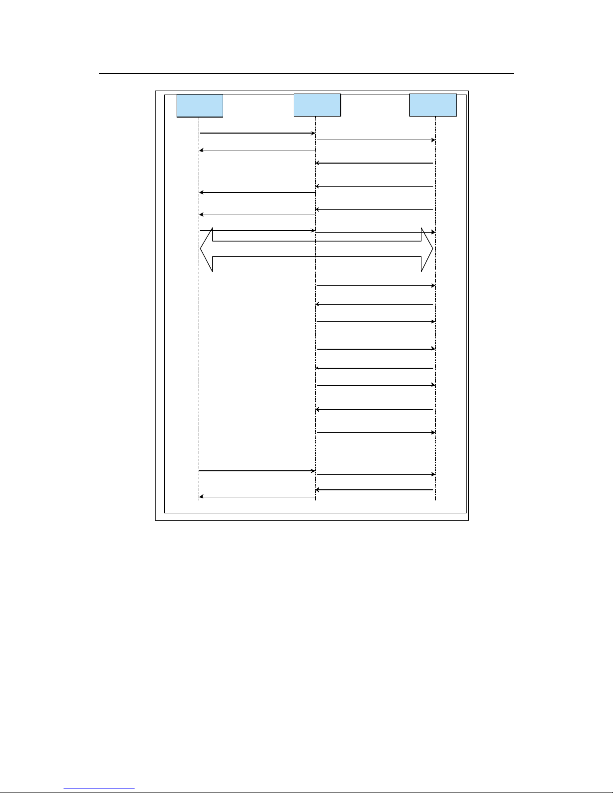
Technical Manual
U-SYS MRS6100 Media Resource Server
Chapter 5 MGCP and SIP
Huawei Technologies Proprietary
5-55
MRS6100AS
INVITE
100 Trying
180 Ringing
200 OK
AC K
reINVITE
Repuest
annoucement
200 OK
AC K
INFO
200 OK
BYE
200 OK
......
......
SIP
terminal
100 Trying
180 Ringing
200 OK
ACK
BYE
200 OK
RTP
reINVITE
Cancel
annoucem
ent
200 OK
AC K
INVITE
Figure 5-14 Successful call flow
Event 1: AS sends an INVITE request to MRS6100. The request contains SDP-1, the
session attribute of the remote caller SIP entity.
IINVITE sip:annc.BAU.pa%28an%3dfile%3a//welcome4%[email protected] SIP/2.0
From: <sip:[email protected]>;tag=8000
To: sip:annc.BAU.pa%28an%3dfile%3a//welcome4%[email protected]
Contact: sip:182.20.62.2
Call-ID: [email protected]
CSeq: 10 INVITE
Page 81

Technical Manual
U-SYS MRS6100 Media Resource Server
Chapter 5 MGCP and SIP
Huawei Technologies Proprietary
5-56
Content-Length: 214
Content-Type: application/sdp
Via: SIP/2.0/UDP 182.20.62.2:5060
User-Agent: MRS6100 DP
v=0
o=TestTeam 4000 4000 IN IP4 182.20.62.2
s=phone-call
c=IN IP4 182.20.70.2
t=0 0
m=audio 8000 RTP/AVP 0 4 8 96 97
a=rtpmap:96 telephone-event/8000/1
a=rtpmap:97 red/8000/1
a=ptime:20
a=x-ssrc:00a6a390
For interpretation of each line, refer to "Request message parameters" in Section
5.3.5 1, "Request messages".
Event 2: MRS6100 returns a 100 Trying response to AS, to notify it that MRS6100 has
received and is processing the request.
SIP/2.0 100 Trying
From: <sip:[email protected]>;tag=8000
To: <sip:annc.BAU.pa%28an%3dfile%3a//welcome4%[email protected]>
CSeq: 10 INVITE
Call-ID: [email protected]
Via: SIP/2.0/UDP 182.20.62.2:5060
Content-Length: 0
Event 3: MRS6100 sends 180 Ringing to AS, and then AS forwards it to the remote
caller SIP entity.
SIP/2.0 180 Ringing
From: <sip:[email protected]>;tag=8000
To:<sip:annc.BAU.pa%28an%3dfile%3a//welcome4%[email protected]>;tag=1a1e0a
19
CSeq: 10 INVITE
Call-ID: [email protected]
Via: SIP/2.0/UDP 182.20.62.2:5060
Page 82

Technical Manual
U-SYS MRS6100 Media Resource Server
Chapter 5 MGCP and SIP
Huawei Technologies Proprietary
5-57
Contact:<sip:annc.BAU.pa%28an%3dfile%3a//welcome4%[email protected]:5061;tr
ansport=udp>
Content-Length: 0
Event 4: MRS6100 sends the 200 OK message to AS, which contains the SDP-2.
SIP/2.0 200 OK
From: <sip:[email protected]>;tag=8000
To:<sip:annc.BAU.pa%28an%3dfile%3a//welcome4%[email protected]>;tag=1a1e0a
19
CSeq: 10 INVITE
Call-ID: [email protected]
Via: SIP/2.0/UDP 182.20.62.2:5060
Contact:<sip:annc.BAU.pa%28an%3dfile%3a//welcome4%[email protected]:5061;tr
ansport=udp>
Content-Length: 288
Content-Type: application/sdp
v=0
o=HuaweiMRS6100 1073743905 1073743905 IN IP4 182.20.60.1
s=Sip Call
c=IN IP4 182.20.60.30
t=0 0
m=audio 10008 RTP/AVP 0 4 8 96 97 18
a=rtpmap:0 PCMU/8000
a=rtpmap:4 G723/8000
a=rtpmap:8 PCMA/8000
a=rtpmap:96 telephone-event/8000
a=rtpmap:97 red/8000
a=rtpmap:18 G729/8000
For interpretation of each line, refer to "Request message parameters" in Section
5.3.5 1, "Request messages".
Event 5: AS sends an ACK message to MRS6100, acknowledging the receipt of the
final response to the INVITE request from MRS6100.
ACK sip:annc.BAU.pa%28an%3dfile%3a//welcome4%[email protected] SIP/2.0
From: <sip:[email protected]>;tag=8000
Page 83

Technical Manual
U-SYS MRS6100 Media Resource Server
Chapter 5 MGCP and SIP
Huawei Technologies Proprietary
5-58
To:<sip:annc.BAU.pa%28an%3dfile%3a//welcome4%[email protected]>;tag=1a1e0a
19
Call-ID: [email protected]
CSeq: 10 ACK
Via: SIP/2.0/UDP 182.20.62.2:5060
User-Agent: MRS6100 DP
Content-Length: 0
A call between AS and MRS6100 is established successfully. An RTP media stream
connection is established between MRS6100 and the remote caller SIP entity.
MRS6100 starts to play welcome4.chi files for the user.
Event 6: AS sends the request for canceling the announcement playing operation with
the reINVITE command.
INVITE sip:[email protected] SIP/2.0
From: <sip:[email protected]>;tag=8000
To:<sip:annc.BAU.pa%28an%3dfile%3a//welcome4%[email protected]>;tag=1a1e0a
19
Contact: sip:182.20.62.2
Call-ID: [email protected]
CSeq: 13 INVITE
Content-Length: 0
Content-Type: application/sdp
Via: SIP/2.0/UDP 182.20.62.2:5060
User-Agent: MRS6100 DP
Event 7:MRS6100 response the opration request.
SIP/2.0 100 Trying
From: <sip:[email protected]>;tag=8000
To:<sip:annc.BAU.pa%28an%3dfile%3a//welcome4%[email protected]>;tag=1a1e0a
19
CSeq: 13 INVITE
Call-ID: [email protected]
Via: SIP/2.0/UDP 182.20.62.2:5060
Content-Length: 0
Event 8: MRS6100 sends 200 OK, indicating the cancellation of announcement
playing.
SIP/2.0 200 OK
Page 84

Technical Manual
U-SYS MRS6100 Media Resource Server
Chapter 5 MGCP and SIP
Huawei Technologies Proprietary
5-59
From: <sip:[email protected]>;tag=8000
To:<sip:annc.BAU.pa%28an%3dfile%3a//welcome4%[email protected]>;tag=1a1e0a
19
CSeq: 13 INVITE
Call-ID: [email protected]
Via: SIP/2.0/UDP 182.20.62.2:5060
Contact:<sip:annc.BAU.pa%28an%3dfile%3a//welcome4%[email protected]:5061;tr
ansport=udp>
Content-Length: 0
Event 9: AS sends an ACK message to MRS6100, acknowledging the receipt of the
final response to the reINVITE request from MRS6100.
ACK sip:[email protected] SIP/2.0
From: <sip:[email protected]>;tag=8000
To:<sip:annc.BAU.pa%28an%3dfile%3a//welcome4%[email protected]>;tag=1a1e0a
19
Call-ID: [email protected]
CSeq: 13 ACK
Via: SIP/2.0/UDP 182.20.62.2:5060
User-Agent: MRS6100 DP
Content-Length: 0
Event 10: AS sends the announcement playing request with the reINVITE command,
while playing the welcome1.chi audio file.
INVITE sip:annc.BAU.pa%28an%3dfile%3a//welcome1%[email protected] SIP/2.0
From: <sip:[email protected]>;tag=8000
To:<sip:annc.BAU.pa%28an%3dfile%3a//welcome4%[email protected]>;tag=1a1e0a
19
Contact: sip:182.20.62.2
Call-ID: [email protected]
CSeq: 1163751 INVITE
Content-Length: 0
Content-Type: application/sdp
Via: SIP/2.0/UDP 182.20.62.2:5060
User-Agent: MRS6100 DP
SIP/2.0 100 Trying
From: <sip:[email protected]>;tag=8000
Page 85

Technical Manual
U-SYS MRS6100 Media Resource Server
Chapter 5 MGCP and SIP
Huawei Technologies Proprietary
5-60
To:<sip:annc.BAU.pa%28an%3dfile%3a//welcome4%[email protected]>;tag=1a1e0a
19
CSeq: 1163751 INVITE
Call-ID: [email protected]
Via: SIP/2.0/UDP 182.20.62.2:5060
Content-Length: 0
Event 11: MRS6100 sends 200 OK, indicating the success of announcement playing
request.
SIP/2.0 200 OK
From: <sip:[email protected]>;tag=8000
To:<sip:annc.BAU.pa%28an%3dfile%3a//welcome4%[email protected]>;tag=1a1e0a
19
CSeq: 1163751 INVITE
Call-ID: [email protected]
Via: SIP/2.0/UDP 182.20.62.2:5060
Contact:<sip:annc.BAU.pa%28an%3dfile%3a//welcome4%[email protected]:5061;tr
ansport=udp>
Content-Length: 0
Event 12: AS sends an ACK message to MRS6100, acknowledging the receipt of the
final response to the reINVITE request from MRS6100.
ACK sip:annc.BAU.pa%28an%3dfile%3a//welcome1%[email protected] SIP/2.0
From: <sip:[email protected]>;tag=8000
To:<sip:annc.BAU.pa%28an%3dfile%3a//welcome4%[email protected]>;tag=1a1e0a
19
Call-ID: [email protected]
CSeq: 1163751 ACK
Via: SIP/2.0/UDP 182.20.62.2:5060
User-Agent: MRS6100 DP
Content-Length: 0
Event 13: After playing announcements, MRS6100 reports the result to AS with the
INFO message, describing the success or failure of announcement playing.
INFO sip:182.20.62.2 SIP/2.0
From:<sip:annc.BAU.pa%28an%3dfile%3a//welcome4%[email protected]>;tag=1a1
e0a19
To: <sip:[email protected]>;tag=8000
Page 86

Technical Manual
U-SYS MRS6100 Media Resource Server
Chapter 5 MGCP and SIP
Huawei Technologies Proprietary
5-61
CSeq: 1 INFO
Call-ID: [email protected]
Via: SIP/2.0/UDP 182.20.60.1:5061;branch=z9hG4bK3e8156831
Max-Forwards: 70
Content-Length: 34
Content-Type: application/Huawei
Event-Type=ivr
Event-Content=OC
Event 14: AS returns the INFO message response.
SIP/2.0 200 OK
From:<sip:annc.BAU.pa%28an%3dfile%3a//welcome4%[email protected]>;tag=1a1
e0a19
To: <sip:[email protected]>;tag=8000
CSeq: 1 INFO
Call-ID: [email protected]
Via: SIP/2.0/UDP 182.20.60.1:5061;branch=z9hG4bK3e8156831
Content-Length: 0
Event 15: AS sends a BYE message, requesting to release the connection.
BYE sip:annc.BAU.pa%28an%3dfile%3a//welcome4%[email protected] SIP/2.0
From: <sip:[email protected]>;tag=8000
To:<sip:annc.BAU.pa%28an%3dfile%3a//welcome4%[email protected]>;tag=1a1e0a
19
Call-ID: [email protected]
CSeq: 352758950 BYE
Via: SIP/2.0/UDP 182.20.62.2:5060
User-Agent: MRS6100 DP
Content-Length: 0
Event 16: MRS6100 returns the BYE response, indicating the connection has been
released.
SIP/2.0 200 OK
From: <sip:[email protected]>;tag=8000
To:<sip:annc.BAU.pa%28an%3dfile%3a//welcome4%[email protected]>;tag=1a1e0a
19
CSeq: 352758950 BYE
Call-ID: [email protected]
Page 87
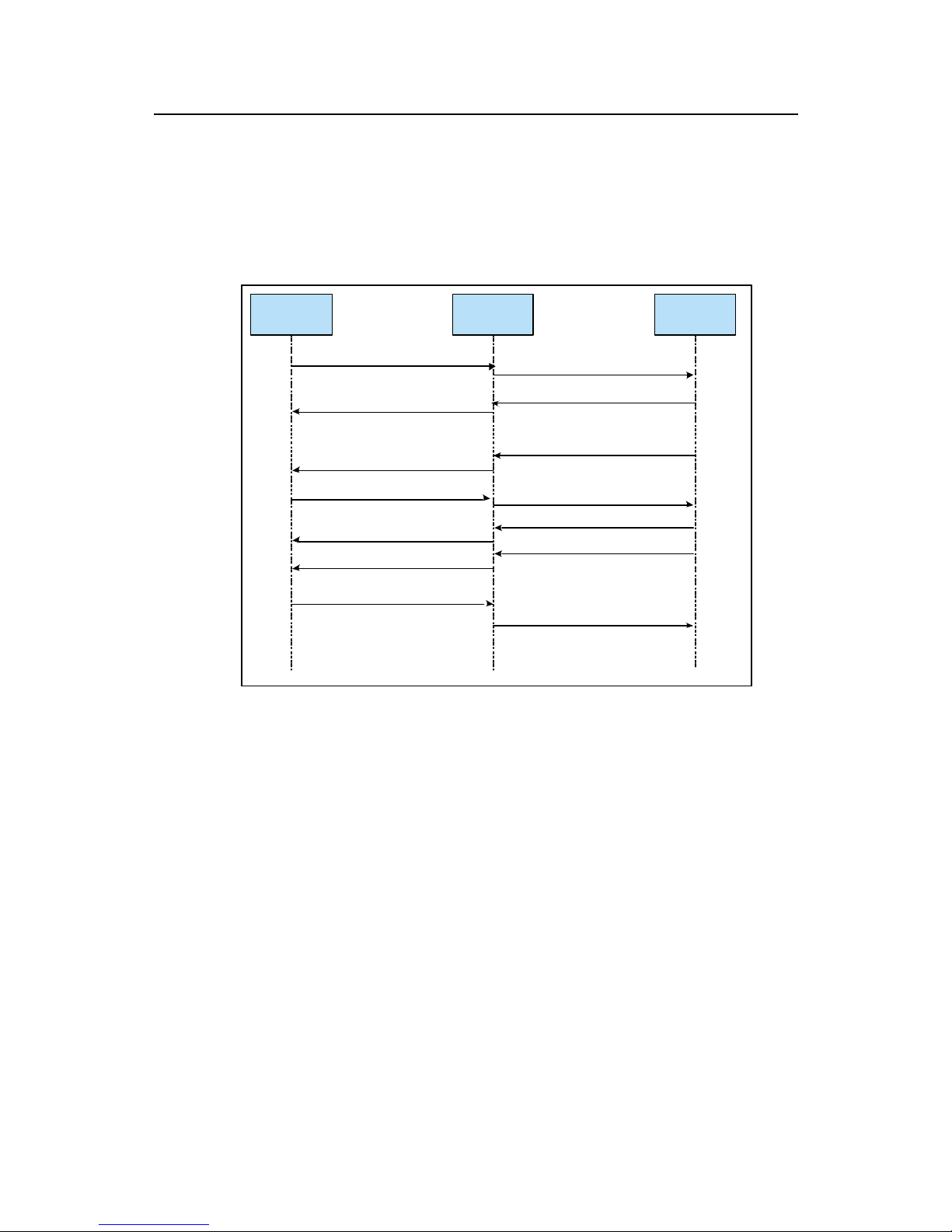
Technical Manual
U-SYS MRS6100 Media Resource Server
Chapter 5 MGCP and SIP
Huawei Technologies Proprietary
5-62
Via: SIP/2.0/UDP 182.20.62.2:5060
Content-Length: 0
II. Unsuccessful call flow
In an unsuccessful call flow shown in Figure 5-15, UA deletes the call in the process of
creating a session. It sends a CANCEL message that results in the call failure.
MR S6 10 0AS
INVITE
100 Trying
180 Ringing
CANCEL
200 for CANCEL
487 for INVITE
ACK
SIP
terminal
SIP
INVITE
100 Trying
180 Ringing
CANCEL
200 for CANCEL
4XX for INVITE
ACK
MR S6 10 0AS
INVITE
100 Trying
180 Ringing
CANCEL
200 for CANCEL
487 for INVITE
ACK
SIP
terminal
INVITE
100 Trying
180 Ringing
CANCEL
200 for CANCEL
4XX for INVITE
ACK
Figure 5-15 Unsuccessful call flow
Event 1: AS sends an INVITE request to MRS6100, containing SDP-1, the session
attribute of the remote caller SIP entity.
INVITE
sip:annc.BAU.pa%28an%3dfile%3a//welcome2%20it%3d2%20iv%3d20%[email protected]
0.60.1 SIP/2.0
From: <sip:[email protected]>;tag=5220000
To:sip:annc.BAU.pa%28an%3dfile%3a//welcome2%20it%3d2%20iv%3d20%29@18
2.20.60.1
Contact: sip:182.20.62.2
Call-ID: [email protected]
CSeq: 10 INVITE
Content-Length: 214
Content-Type: application/sdp
Page 88

Technical Manual
U-SYS MRS6100 Media Resource Server
Chapter 5 MGCP and SIP
Huawei Technologies Proprietary
5-63
Via: SIP/2.0/UDP 182.20.62.2:5060
User-Agent: MRS6100 DP
v=0
o=TestTeam 2000 2000 IN IP4 182.20.62.2
s=phone-call
c=IN IP4 182.20.69.4
t=0 0
m=audio 8766 RTP/AVP 0 4 8 96 97
a=rtpmap:96 telephone-event/8000/1
a=rtpmap:97 red/8000/1
a=ptime:20
a=x-ssrc:00a6a390
For interpretation to each line, refer to "Request message parameters" in Section
5.3.5 1, "Request messages".
Event 2: MRS6100 returns a 100 Trying response to AS, to notify it that MRS6100 has
received and is processing the request. .
SIP/2.0 100 Trying
From: <sip:[email protected]>;tag=5220000
To:<sip:annc.BAU.pa%28an%3dfile%3a//welcome2%20it%3d2%20iv%3d20%29@1
82.20.60.1>
CSeq: 10 INVITE
Call-ID: [email protected]
Via: SIP/2.0/UDP 182.20.62.2:5060
Content-Length: 0
Event 3: MRS6100 sends 180 Ringing to AS, and then AS sends it to the remote
caller SIP entity.
SIP/2.0 180 Ringing
From: <sip:[email protected]>;tag=5220000
To :
<sip:annc.BAU.pa%28an%3dfile%3a//welcome2%20it%3d2%20iv%3d20%29@182.
20.60.1>;tag=68a574c9
CSeq: 10 INVITE
Call-ID: [email protected]
Via: SIP/2.0/UDP 182.20.62.2:5060
Page 89

Technical Manual
U-SYS MRS6100 Media Resource Server
Chapter 5 MGCP and SIP
Huawei Technologies Proprietary
5-64
Contact:
<sip:annc.BAU.pa%28an%3dfile%3a//welcome2%20it%3d2%20iv%3d20%29@182.
20.60.1:5061;transport=udp>
Content-Length: 0
Event 4: AS sends a CANCEL message to MRS6100 to cancel the current session.
CANCEL
sip:annc.BAU.pa%28an%3dfile%3a//welcome2%20it%3d2%20iv%3d20%[email protected]
0.60.1 SIP/2.0
Via: SIP/2.0/UDP 182.20.62.2:5060
From: <sip:[email protected]>;tag=5220000
To:<sip:annc.BAU.pa%28an%3dfile%3a//welcome2%20it%3d2%20iv%3d20%29@1
82.20.60.1>
Call-ID: [email protected]
CSeq: 10 CANCEL
Content-Length: 0
User-Agent: MRS6100 DP
Event 5: MRS6100 returns the CANCEL response.
SIP/2.0 200 OK
From: <sip:[email protected]>;tag=5220000
To:<sip:annc.BAU.pa%28an%3dfile%3a//welcome2%20it%3d2%20iv%3d20%29@1
82.20.60.1>
CSeq: 10 CANCEL
Call-ID: [email protected]
Via: SIP/2.0/UDP 182.20.62.2:5060
Content-Length: 0
Event 6: MRS6100 returns the final response to the INVITE request.
SIP/2.0 487 Request Terminated
From: <sip:[email protected]>;tag=5220000
To:<sip:annc.BAU.pa%28an%3dfile%3a//welcome2%20it%3d2%20iv%3d20%29@1
82.20.60.1>;tag=68a574c9
CSeq: 10 INVITE
Call-ID: [email protected]
Via: SIP/2.0/UDP 182.20.62.2:5060
Content-Length: 0
Page 90

Technical Manual
U-SYS MRS6100 Media Resource Server
Chapter 5 MGCP and SIP
Huawei Technologies Proprietary
5-65
Event 7: AS sends an ACK message to MRS6100, acknowledging the receipt of the
final response to the INVITE request from MRS6100.
ACK
sip:annc.BAU.pa%28an%3dfile%3a//welcome2%20it%3d2%20iv%3d20%[email protected]
0.60.1 SIP/2.0
Via: SIP/2.0/UDP 182.20.62.2:5060
From: <sip:[email protected]>;tag=5220000
To:<sip:annc.BAU.pa%28an%3dfile%3a//welcome2%20it%3d2%20iv%3d20%29@1
82.20.60.1>;tag=68a574c9
Call-ID: [email protected]
CSeq: 10 ACK
User-Agent: MRS6100 DP
Content-Length: 0
Page 91
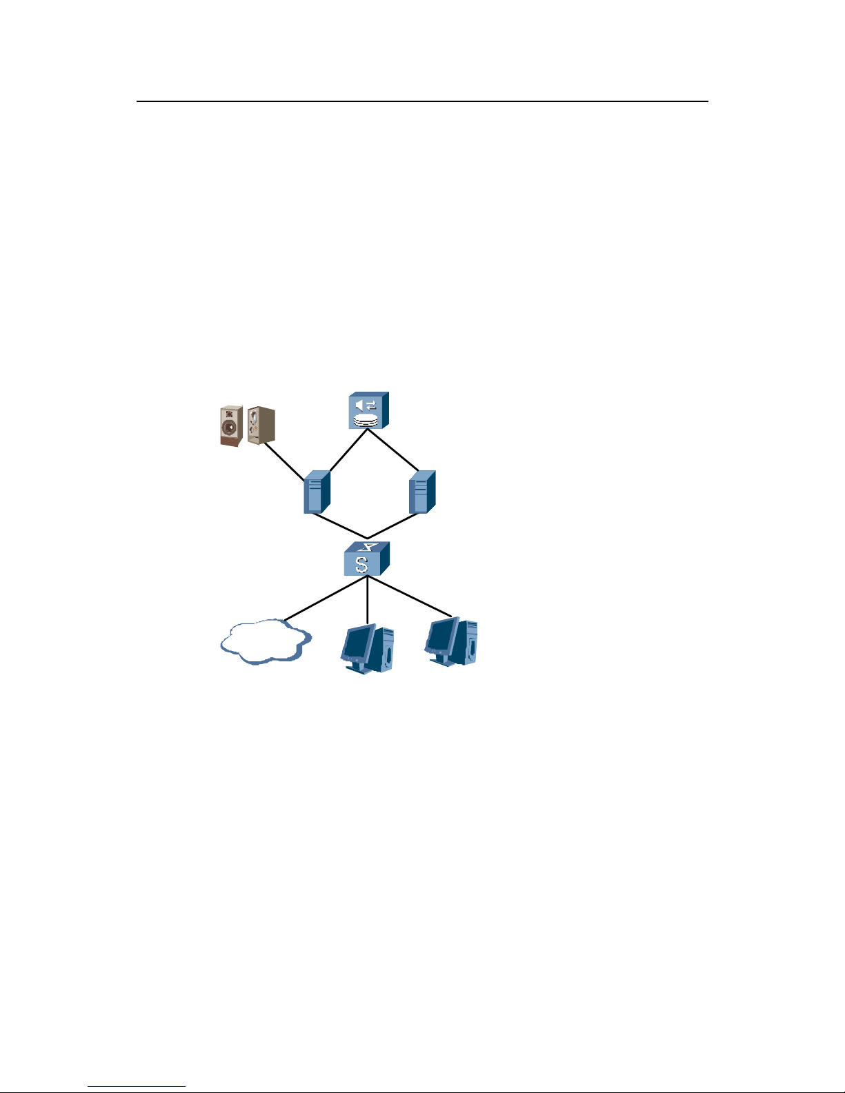
Technical Manual
U-SYS MRS6100 Media Resource Server
Chapter 6 MRS6100 Terminal System
Huawei Technologies Proprietary
6-1
Chapter 6 MRS6100 Terminal System
6.1 System Overview
The MRS6100 terminal system, composed of the BAM server, the O&M WS and the
emergency WS, is responsible for management and maintenance of the entire
system.
6.1.1 Structure of MRS6100 Terminal System
Figure 6-1 shows the structure of the MRS6100 terminal system.
Lan Switch
WS
BAM Server
Emergency Server
To Network
Management Center
WAN
Alarm Box
WS
Figure 6-1 Structure of MRS6100 terminal system
The EAM board in the figure is the BAM server of MRS6100 system.
6.1.2 Structure of the Terminal System Software
The software of MRS6100 terminal system includes a local maintenance system
(BAM, WS and communication gateway) and a network management system (NMS).
The local maintenance system is the compulsory part of MRS6100 terminal system,
while the NMS is optional. The logic structure of MRS6100 terminal system is shown
in
Figure 6-2.
Page 92
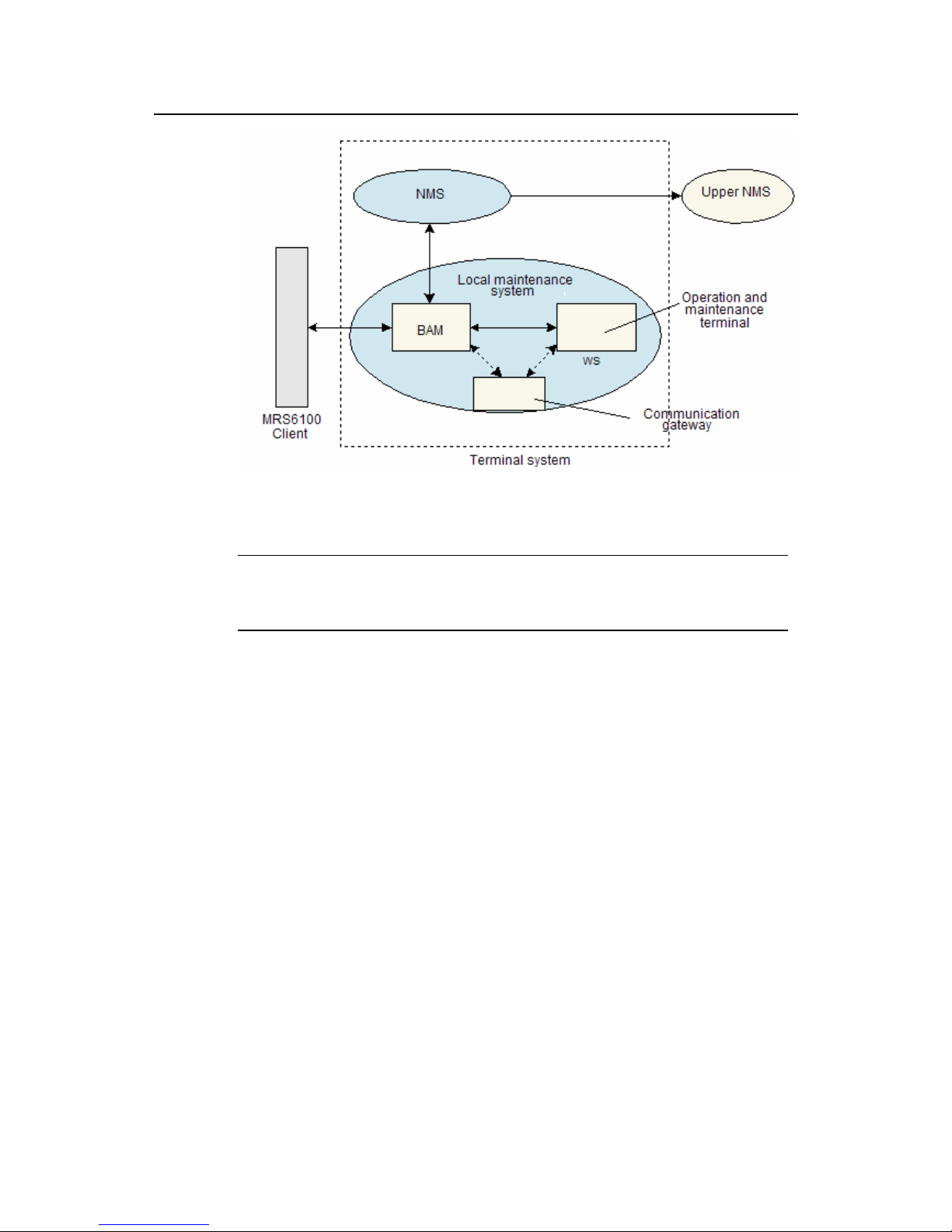
Technical Manual
U-SYS MRS6100 Media Resource Server
Chapter 6 MRS6100 Terminal System
Huawei Technologies Proprietary
6-2
Figure 6-2 Logic structure of the terminal system
Note:
For working principles of the NMS software, refer to the related user manual.
The BAM communicates with the FAM, implementing system operation and
maintenance, and bill management.
The BAM and the NMS interact through the standard man-machine language
(MML)/simple network management protocol (SNMP), thereby realizing the
centralized maintenance and management of MRS6100 by the NMS. The NMS
provides an access interface to its upper NMS.
The BAM and workstations communicate with each other using TCP/IP through
Ethernet. They can also communicate using serial port through communication
gateway.
6.2 BAM Server
The BAM is the server of the MRS6100 operation and maintenance system (OMS). It
works as a bridge between the OMS and the terminals. The BAM sends the local or
remote OMS commands to the host. The host then directs the response to the related
terminal devices to dump or forward the alarm messages or service statistics. The
MRS6100 uses HUAWEI C5210 server as the BAM server.
The BAM software is used to manage and maintain the MRS6100, including the
operating data of the MRS6100, traffic statistics and alarm information. The MRS6100
Page 93
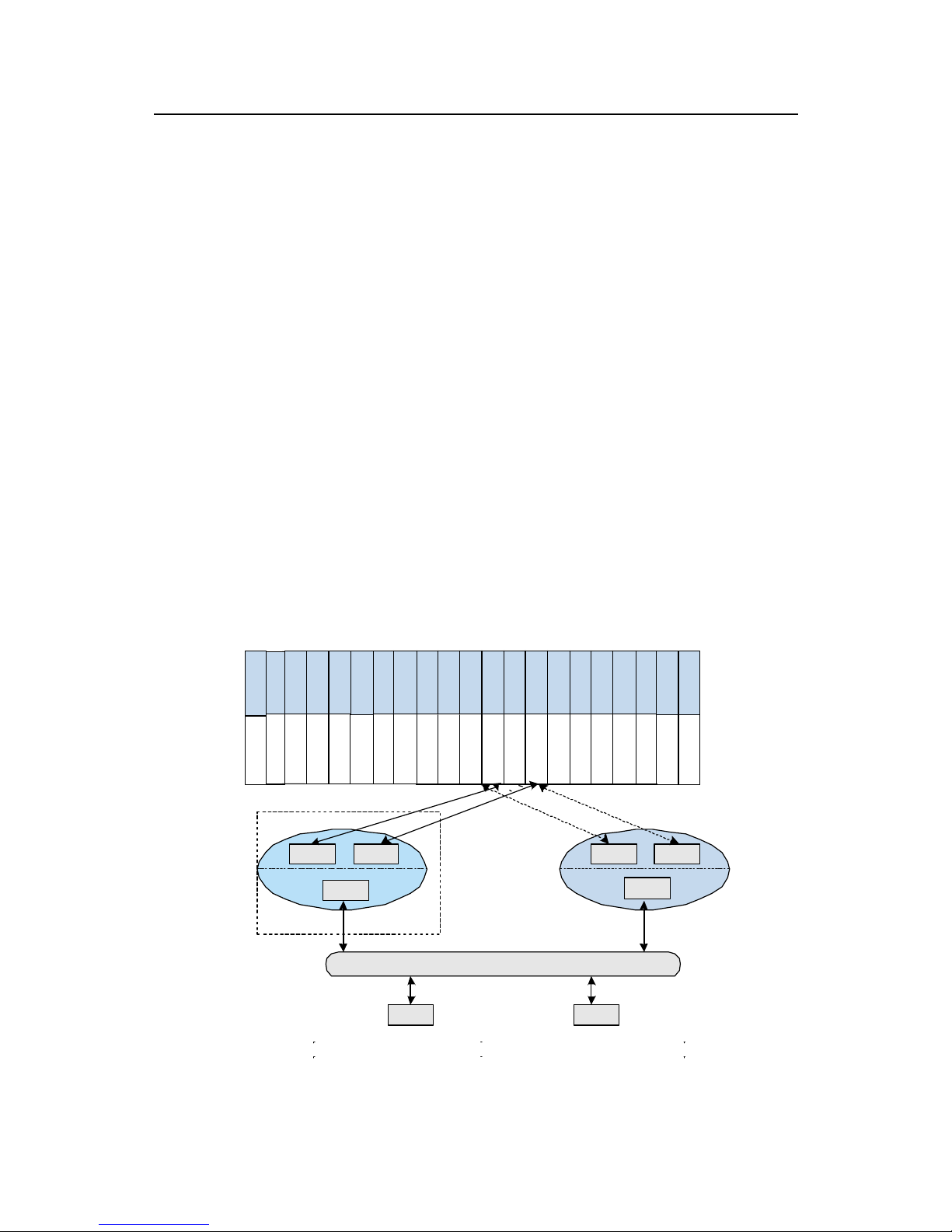
Technical Manual
U-SYS MRS6100 Media Resource Server
Chapter 6 MRS6100 Terminal System
Huawei Technologies Proprietary
6-3
provides a complete set of practical operation and maintenance methods and tools, to
guarantee the normal running of the system, minimize the business cost, and improve
the quality of communication service.
6.2.1 BAM Networking
The BAM is the core of the local operation and maintenance system. Being the
TCP/IP server, the BAM responds to connection requests from clients (or
workstations), creates connections, analyzes commands from clients, and carries out
appropriate processing. Meanwhile, the BAM responds to connection requests from
the equipment, creates connections, achieves the communication between the BAM
and the equipment, and receives and processes data loading requests and alarms
from the equipment.
The BAM provides two network interfaces to core LAN Switches, thereby being
connected to the HSCIs in the basic frames. The two network interfaces provided by
the BAM are respectively in the same network segment with the active/standby
SMUIs (two closed LANs connected to the equipment). The connection to a client
belongs to a different network segment (an open operation and maintenance LAN).
The three network segments are not seeable with each other. In this way, the network
security is ensured to a certain extent and the dependence on the system security is
reduced. The network configuration of the BAM is shown in
Figure 6-3.
S
M
U
I
NIC1
NIC2
NIC3
NIC1
NIC2
NIC3
LAN
WS0 WS1
BAM s erver
Emergency ws
MR S6100
H
S
C
I
S
I
U
I
S
M
U
I
H
S
C
I
S
I
U
I
BAM: Back administration module WS: Work station
NIC: Network interface card LAN: Local area network
Page 94
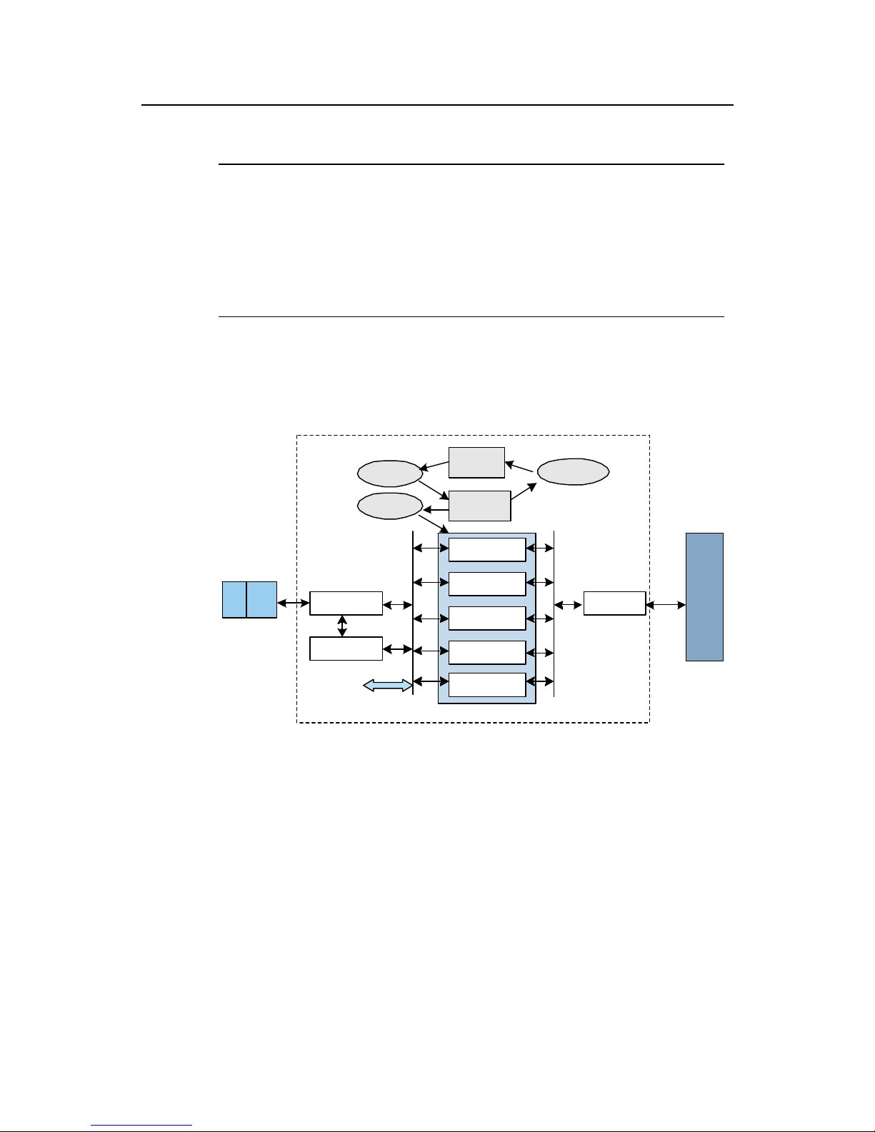
Technical Manual
U-SYS MRS6100 Media Resource Server
Chapter 6 MRS6100 Terminal System
Huawei Technologies Proprietary
6-4
Figure 6-3 BAM networking
Note:
z The BAM server implements the back administration function of the MRS6100.
z The NIC1 and the NIC2 of the BAM communicate with other boards through the
HSCI.
z The fixed IP address of the NIC1 is 172.20.200.0. The fixed IP address of the NIC2
is 172.30.200.0.
6.2.2 Components of the BAM Software
The components of the BAM software are shown in Figure 6-4.
Warn
Maintain
Dataman
Stats
Security
Manager
BAM
Service
Monitor
Monitor
Shake hand
ExchangeMML Server
LogMan
SQL Server
DeviceMML GUI
WS
BAM
SNTPClient
Figure 6-4 BAM software components
The BAM software is composed of the following parts:
z SQL (sequential query language) Server: Storing various service data and
providing database support for various service servers.
z Logman: An operation log process, responsible for recording the operation log
and providing the log query function and malicious operation tracing function for
clients.
z MML Server: Communicating with workstations, managing operator authorities,
interpreting WS input commands, and dispatching WS commands.
z SNMP Agent: Providing a standard SNMP interface for the NMS.
Page 95

Technical Manual
U-SYS MRS6100 Media Resource Server
Chapter 6 MRS6100 Terminal System
Huawei Technologies Proprietary
6-5
z Exchange: A communication module between the BAM and the equipment,
responsible for providing program and data loading functions and dispatching
messages returned from the equipment.
z Security Manager: A management functional module of the whole equipment
software, responsible for managing other service processing modules, including
monitoring their running state.
z BAM Service: Monitoring the Security Manager, when appropriate, restarting the
BAM server.
z Statistics: A traffic measurement (or called traffic statistics) process, responsible
for processing traffic measurement data, for example, creating traffic
measurement tasks and querying measurement results.
z SNTPClient: The SNTP Client. It collects the server time and synchronizes the
client time.
z Warn: A warning process, responsible for processing equipment alarms and
BAM alarms, providing alarm reports and alarm query functions for workstations,
and driving the alarm box.
z Maintain: A maintenance process, responsible for processing equipment
maintenance commands, such as patching programs and tracing signaling.
z Dataman: A data configuration process, responsible for processing data
configuration and data backup, such as processing call prefixes and equipment
data.
6.2.3 Characteristics of BAM
1) High reliability
A carrier-class SQL Server is used as a large database system. The programs are
designed with multi-layer self-monitoring measures so as to achieve data backup and
recovery conveniently, and ensure data security.
2) Client/Server structure
The BAM software is integrated with communication server and database server.
Various maintenance tasks are carried out in the Client/Server mode. The software
supports local and remote maintenance tasks to set data simultaneously.
Maintenance operations can be performed conveniently and quickly.
3) Remote maintenance
The MRS6100 provides remote maintenance functions and supports flexible
networking modes. It can be connected with a remote maintenance system through
Internet.
The following details a commonly used method, iWeb remote maintenance solution.
As shown in
Figure 6-5, HUAWEI iWeb remote maintenance system, based on
Internet, enhances remote monitoring and encrypted data transmission, thereby
ensuring the security of the equipment running.
Page 96
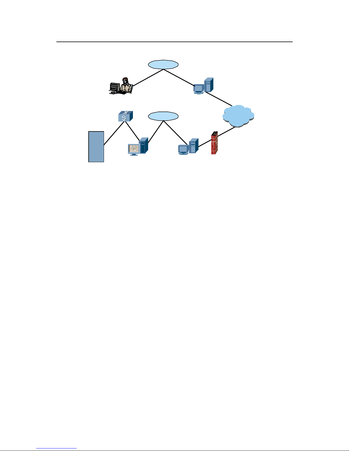
Technical Manual
U-SYS MRS6100 Media Resource Server
Chapter 6 MRS6100 Terminal System
Huawei Technologies Proprietary
6-6
Device
Remote WS Proxy Host
Internet
FirewallBAM
LAN Switch
Server Agent
Client Agent
LAN
LAN
Client Agent:
Client Agent: Receiving data from remote maintenance workstations and
transferring the data to the Server Agent
Server Agent:
Server Agent: Receiving data from the Client Agent and transferring the
data to the BAM
Proxy HOST: Proxy server
Figure 6-5 Networking model of iWeb remote maintenance solution
The iWeb remote maintenance system has the following characteristics:
z Unnecessary to change the original system: Operation and maintenance
personnel can maintain MRS6100 through the iWeb remote maintenance
system in a remote mode.
z Data transfer: A bi-directional data channel is established between the Client
Agent and the Server Agent and between the remote maintenance workstation
and the BAM, to transfer ordinary requests and active reports between the
remote maintenance workstation and the BAM.
z Supporting to traverse Proxy and firewall: MRS6100 supports user
authentication and WindowsNT Challenge/Response (NTLM) authentication at
the Proxy Server. Through the tunnel technique based on hyper text transport
protocol (HTTP), the firewall can open an HTTP port to achieve the traverse
through firewall.
z Encrypting and compressing data: Before being transferred, data are encrypted
to ensure security and is compressed to save the bandwidth.
z Access policy control: authorization based on the IP address of a remote
maintenance workstation, authorization based on a time segment and real-time
authorization for an unauthorized remote maintenance workstation.
z Remote maintenance communication: MRS6100 supports the communication
between remote maintenance personnel and local maintenance personnel in the
text form, thus saving phone call fees during the maintenance.
Page 97

Technical Manual
U-SYS MRS6100 Media Resource Server
Chapter 6 MRS6100 Terminal System
Huawei Technologies Proprietary
6-7
z Remote maintenance monitoring in real time: MRS6100 supports to monitor
maintenance operations and requests from remote clients in real time. In addition,
it supports the disconnection with suspicious clients.
z Remote maintenance logs and reports: MRS6100 supports to record all
maintenance operations at the client for future reference and supports to
generate a report recording the maintenance operations at the client.
4) Man-machine command line and GUI interface
It provides MML command line interfaces conforming to the ITU-T recommendation,
and also provides GUIs.
z MML
A user can conduct data configuration, performance management, operation and
maintenance on MRS6100 through MML.
z GUI
A user can manage alarm information, trace signaling and interfaces, and observe
device state through GUI.
5) Openness
It uses the standard TCP/IP protocol and distributed database technology, conforming
to the Open Systems Interconnection (OSI) reference of the International Standard
Organization (ISO). The MRS6100 can be connected to various large databases with
transparent access, thereby easily providing various value-added services and
IN-supported services. When necessary, a user can install peripheral devices such as
optical disk drive, hard disk array, tape drive and printer. Moreover, it is easy to add
more operation and maintenance terminals.
6) Optimized security measures
z The log function provided by the BAM enables operators to correctly record all
operations.
z The MRS6100 supports to isolate a private network from the public network,
thereby achieving screening from outside.
z The relationship among configured data is not visible to users, which ensures
data consistency.
z The MRS6100 supports to back up data on schedule, thereby improving the
system ability of resisting emergencies.
Page 98

Technical Manual
U-SYS MRS6100 Media Resource Server
Chapter 6 MRS6100 Terminal System
Huawei Technologies Proprietary
6-8
6.3 Operation and Maintenance Workstation
The Windows 2000 Server operating system, the Windows 2000 Professional
operating system or the Windows XP operation system is installed on the operation
and maintenance workstation, running the software at the operation and maintenance
client. It communicates with BAM, achieving local and remote operation and
maintenance functions. Workstations and the BAM can communicate through local
area network (LAN), wide area network (WAN), or serial port.
In the client/server mechanism, an MRS6100 operation and maintenance terminal
functions as a client and the BAM as a server. A client provides operation and
maintenance interfaces for users. The OMC software provides MML-based graphical
terminals, mainly window operation interfaces. The OMC software is composed of the
service maintenance system, the alarm console, and the traffic measurement report
system.
I. Service maintenance system
The MML-based graphical terminal software is composed of the following functional
modules:
1) MML navigation tree module
The MML navigation tree provides an operator with basic operation command sets of
MRS6100. Command sets with the same properties are classified on the same
branch of the navigation tree. Expand the MML command tree, and the operator can
find a number of MML command nodes. Double click an MML command node, and
the corresponding command input window and prompt window can be opened. The
operator only needs to type a command and set values for parameters, and the MML
module automatically generates a command report to dispatch. Through the MML
module, the operator can perform various operations on MRS6100, such as data
configuration, performance management, and subscriber management.
2) Maintenance navigation tree module
The maintenance navigation tree provides an operator with maintenance command
sets. The maintenance includes trace maintenance and device panel maintenance.
The maintenance navigation tree module provides the following functions:
z Maintenance management
The system provides multiple maintenance control methods such as query, display,
switchover, reset, isolation, block and activation. With these maintenance control
methods, efficient management and maintenance can be performed on the hardware
components, system resources, signaling links, clock links and physical ports of the
SoftSwitch system, as well as the gateways and terminals under its control.
z Tracing management
Page 99

Technical Manual
U-SYS MRS6100 Media Resource Server
Chapter 6 MRS6100 Terminal System
Huawei Technologies Proprietary
6-9
The system provides functions such as connection tracing, signaling tracing, interface
tracing and message interpretation. With these functions, a real-time and dynamic
trace can be conducted on the connection process, state transition, resource usage,
telephone number information transfer and control information streams related to
terminal users, trunk circuits, signaling links and interface protocols. The tracing
information can be preserved for future reference. In this way, the system provides
powerful fault analysis and location capabilities for users.
z Signaling analysis
The system provides embedded signaling analysis tool software developed
independently by Huawei. The software works along with the trace management
functions to analyze the signaling interaction processes in an online or offline mode.
The system provides strong maintenance approaches to quickly locate fault causes
and optimize the signaling link configuration.
II. Alarm console
The alarm console correctly reflects the alarms recorded in the BAM in real time.
Through the alarm console, an operator can query and view all alarms, and manage
the alarms as well.
Alarm information includes the alarm name, generation (and restoration) time, alarm
level, location information, and restoration suggestions.
III. Traffic measurement report system
The traffic measurement (traffic statistics) system performs measurements and
statistics on the services and objects of various call types. By analyzing the statistic
data, the system knows the running conditions of the SoftSwitch, the gateways, the
whole network and the terminals. Therefore, it provides the basic data for the planning,
design, operation, management and maintenance of the telecommunication network.
6.4 Emergency Workstation
The emergency workstation software is installed on the emergency workstation. It can
automatically synchronize (back up) data contents in the BAM server through the
network (a synchronization request is originated every four hours by default). Once
the BAM server stops running, the emergency workstation can restore the BAM
database by using these backup data, and serve as the BAM server temporarily.
When the BAM server is recovered, the emergency workstation then is switched over
to the original working mode. Therefore, the emergency workstation is mainly used as
the backup device for the system BAM data.
The MRS6100 emergency WS uses HUAWEI C5210 server.
Table 6-1 lists its basic
hardware configuration.
Page 100

Technical Manual
U-SYS MRS6100 Media Resource Server
Chapter 6 MRS6100 Terminal System
Huawei Technologies Proprietary
6-10
Table 6-1 Basic configuration for the emergency WS
Item Configuration
CPU 2 × Intel Xeon DP 2.4 GHz or higher
Hard disk 2 × 36 GB 10000RPM SCSI hard disks or more
Memory 1 GB or more
Network adapter
2 × 1000M integrated network adapters
2 × 1000M extended network adapters
RAID card Built-in RAID. RAID 0 and RAID 1 are supported.
Video adapter
Integrated ATI Rage XL video controller with 8 MB
buffer
6.5 Communication Gateway Software
Except Ethernet, the communication gateway provides another communication way
between the BAM and workstations, namely, serial communication. To achieve such
communication, you can interconnect the BAM and respective workstations through
serial cables. Communication gateways include MRS6100 Server Gateway Tool and
MRS6100 WorkStation Gateway Tool. They fulfill the protocol conversion between
the TCP/IP network interface and the RS232 serial port.
The communication gateway software of the BAM and workstations includes the
communication gateway software at the BAM and that at the WS. The BAM can be
accessed to the alarm box after the MRS6100 Server Gateway Tool is configured,
including setting serial port numbers and setting the client application type (New
AlarmBox Class).It is suggested that the alarm box be accessed to the emergency
workstation, as shown in
Figure 6-6.
 Loading...