

Huawei USG6600, USG6305-W, USG6308, USG6306, USG6500 Hardware Manual
...
HUAWEI USG6000 Series
V100R001 & V500R001
Hardware Guide
Issue 08
Date 2017-06-30
HUAWEI TECHNOLOGIES CO., LTD.

Copyright © Huawei Technologies Co., Ltd. 2017. All rights reserved.
No part of this document may be reproduced or transmitted in any form or by any means without prior written
consent of Huawei Technologies Co., Ltd.
Trademarks and Permissions
and other Huawei trademarks are trademarks of Huawei Technologies Co., Ltd.
All other trademarks and trade names mentioned in this document are the property of their respective
holders.
Notice
The purchased products, services and features are stipulated by the contract made between Huawei and the
customer. All or part of the products, services and features described in this document may not be within the
purchase scope or the usage scope. Unless otherwise specified in the contract, all statements, information,
and recommendations in this document are provided "AS IS" without warranties, guarantees or
representations of any kind, either express or implied.
The information in this document is subject to change without notice. Every effort has been made in the
preparation of this document to ensure accuracy of the contents, but all statements, information, and
recommendations in this document do not constitute a warranty of any kind, express or implied.
Huawei Technologies Co., Ltd.
Address: Huawei Industrial Base
Bantian, Longgang
Shenzhen 518129
People's Republic of China
Website: http://e.huawei.com
Issue 08 (2017-06-30) Huawei Proprietary and Confidential
Copyright © Huawei Technologies Co., Ltd.
i

HUAWEI USG6000 Series
Hardware Guide
Related Version
The following table lists the product version related to this document.
About This Document
About This Document
Issue 08 (2017-06-30) Huawei Proprietary and Confidential
Copyright © Huawei Technologies Co., Ltd.
ii
HUAWEI USG6000 Series
Hardware Guide
Product Name Version
About This Document
The USG6000 series has the
following models:
l USG6300
– USG6305
– USG6305-W
– USG6306
– USG6308
– USG6310S
– USG6310S-W
– USG6310S-WL-OVS
– USG6310
– USG6320
– USG6330
– USG6350
– USG6360
– USG6370
– USG6380
– USG6390
– USG6390E
l USG6500
– USG6507
– USG6510
– USG6510-WL
– USG6530
– USG6550
– USG6570
l USG6600
– USG6620
– USG6630
– USG6650
– USG6660
– USG6670
– USG6680
V100R001
V500R001
Intended Audience
This document describes hardware structure, installation guide, and hardware maintenance.
The content of this document includes the appearance and specifications of the product, the
Issue 08 (2017-06-30) Huawei Proprietary and Confidential
Copyright © Huawei Technologies Co., Ltd.
iii
NOTE
HUAWEI USG6000 Series
Hardware Guide
supported expansion cards, preparation before the installation, installation, cabling, and
hardware replacement.
This document is intended for installation personnel and administrators who install and
maintain USG. The installation personnel or administrators must have experience in the
installation and maintenance of networking devices.
Symbol Conventions
The symbols that may be found in this document are defined as follows.
About This Document
Symbol
Description
Indicates an imminently hazardous situation which, if not
avoided, will result in death or serious injury.
Indicates a potentially hazardous situation which, if not
avoided, could result in death or serious injury.
Indicates a potentially hazardous situation which, if not
avoided, may result in minor or moderate injury.
Indicates a potentially hazardous situation which, if not
avoided, could result in equipment damage, data loss,
performance deterioration, or unanticipated results.
NOTICE is used to address practices not related to personal
injury.
Calls attention to important information, best practices and
tips.
NOTE is used to address information not related to
personal injury, equipment damage, and environment
deterioration.
Command Conventions
The command conventions that may be found in this document are defined as follows.
Convention
Boldface The keywords of a command line are in boldface.
Italic Command arguments are in italics.
[ ] Items (keywords or arguments) in brackets [ ] are optional.
Issue 08 (2017-06-30) Huawei Proprietary and Confidential
Copyright © Huawei Technologies Co., Ltd.
Description
iv
HUAWEI USG6000 Series
Hardware Guide
Convention Description
{ x | y | ... } Optional items are grouped in braces and separated by
[ x | y | ... ] Optional items are grouped in brackets and separated by
About This Document
vertical bars. One item is selected.
vertical bars. One item is selected or no item is selected.
{ x | y | ... }
[ x | y | ... ]
&<1-n> The parameter before the & sign can be repeated 1 to n
# A line starting with the # sign is comments.
GUI Conventions
The GUI conventions that may be found in this document are defined as follows.
Convention
Boldface Buttons, menus, parameters, tabs, window, and dialog titles
> Multi-level menus are in boldface and separated by the ">"
*
*
Optional items are grouped in braces and separated by
vertical bars. A minimum of one item or a maximum of all
items can be selected.
Optional items are grouped in brackets and separated by
vertical bars. Several items or no item can be selected.
times.
Description
are in boldface. For example, click OK.
signs. For example, choose File > Create > Folder.
Update History
Updates between document issues are cumulative. Therefore, the latest document issue
contains all updates made in previous issues.
Updates in Issue 08 (2017-06-30) of Product Version V500R001C60
The eighth commercial release has the following update:
Added the support of the megabit optical transceiver for the
USG6306/6308/6330/6350/6360/6507/6530. For details, see Megabit Optical Transceiver.
Updates in Issue 07 (2017-03-28) of Product Version V500R001C50
The seventh commercial release has the following updates:
l Added the support of hard disk combination SM-HDD-SAS1200G-B for the 1 U device
(USG6306/6308/6330/6350/6360/6370/6380/6390/6390E/
Issue 08 (2017-06-30) Huawei Proprietary and Confidential
Copyright © Huawei Technologies Co., Ltd.
v

HUAWEI USG6000 Series
Hardware Guide
6507/6530/6550/6570/6620/6630). For details, see Hard Disk Combination SM-HDD-
SAS1200G-B. If you use SM-HDD-SAS1200G-B hard disk combination on
V500R001C50 earlier versions, the SM-HDD-SAS1200G-B hard disk combination will
be identified as non-Huawei hard disks. You need to upgrade the FW version.
l Added the support of hard disk unit SM-HDD-SAS1200G-A for the 3 U device
(USG6650/6660/6670 and USG6680-AC). For details, see Hard Disk Unit SM-HDD-
SAS1200G-A. If you use SM-HDD-SAS1200G-A hard disks on V500R001C50 earlier
versions, the SM-HDD-SAS1200G-A hard disks will be identified as non-Huawei hard
disks. You need to upgrade the FW version.
l The 1 U model (USG6306/6308/6330/6350/6360/6370/6380/6390/6390E/
6507/6530/6550/6570/6620/6630) and 3 U model (USG6650/6660/6670/6680) can be
installed into a 19-inch standard cabinet using the extension guide rail (part number:
21242247).
About This Document
Updates in Issue 06 (2016-08-19) of Product Version V500R001C30SPC100
The sixth commercial release has the following updates:
l Added descriptions of desktop devices USG6305, USG6305-W, USG6310S,
USG6310S-W, USG6310S-WL, USG6510, and USG6510-WL.
l Added the description of the 1 U USG6390E.
l The USG6650/6660/6670 and USG6680-AC support the hard disk unit SM-HDD-
SAS600G-A. For details, see Hard Disk Unit SM-HDD-SAS600G-A. If you use SMHDD-SAS600G-A hard disks on V500R001C20SPC200 earlier versions, the SM-HDDSAS600G-A hard disks will be identified as non-Huawei hard disks. You need to
upgrade the FW version.
l The 1 U model (USG6306/6308/6330/6350/6360/6370/6380/6390/6390E/
6507/6530/6550/6570/6620/6630) supports SM-HDD-SAS600G-B hard disk
combination. For details, see Hard Disk Combination SM-HDD-SAS600G-B. If you
use SM-HDD-SAS600G-B hard disk combination on V500R001C30SPC100 earlier
versions, the SM-HDD-SAS600G-B hard disk combination will be identified as nonHuawei hard disks. You need to upgrade the FW version.
Updates in Issue 05 (2015-07-30) of Product Version V100R001C30SPC100
The fifth commercial release has the following updates:
l Changed the matching power adapter of the USG6320 from 60 W to 36 W. For details,
see USG6310/6320 Power Supply System.
l Changed the BOM code of the 10GE optical module with an 80 km transmission
distance from 02310JFE to 02310SNN, and the corresponding external model from
LE2MXSC80FF0 to SFP-10G-ZR.
Updates in Issue 04 (2015-03-25) of Product Version V100R001C30
The fourth commercial release has the following updates:
l Added the USG6306/6308.
l Added the USG6507.
Updates in Issue 03 (2015-01-26) of Product Version V100R001C20SPC700
The third commercial release has the following updates:
Issue 08 (2017-06-30) Huawei Proprietary and Confidential
Copyright © Huawei Technologies Co., Ltd.
vi

HUAWEI USG6000 Series
Hardware Guide
l The AC power module of the USG6680 is increased from 350 W to 700 W. For details,
see USG6680 Hardware Overview.
l The 1 U device and 3 U device can be mounted in a 19-inch standard cabinet through
adjustable guide rails. For details, see Mounting a 1 U Device in a Cabinet and
Mounting a 3 U Device in a Cabinet.
About This Document
Updates in Issue 02 (2014-10-20) of Product Version V100R001C20SPC200
The second commercial release has the following updates.
The following hardware models are added based on V100R001C10:
l USG6310
l USG6330/6350/6360
l USG6530
l 2.3.1 USG6620/6630
Updates in Issue 01 (2014-06-13) of Product Version V100R001C10SPC100
Initial commercial release.
Issue 08 (2017-06-30) Huawei Proprietary and Confidential
Copyright © Huawei Technologies Co., Ltd.
vii

HUAWEI USG6000 Series
Hardware Guide Contents
Contents
About This Document.....................................................................................................................ii
1 Software Versions Compatible with Hardware...................................................................... 1
2 Hardware Overview......................................................................................................................2
2.1 USG6300 Product Series................................................................................................................................................ 2
2.1.1 USG6305..................................................................................................................................................................... 2
2.1.1.1 Device Overview...................................................................................................................................................... 2
2.1.1.2 Front Panel................................................................................................................................................................3
2.1.1.3 Rear Panel.................................................................................................................................................................4
2.1.1.4 Power Supply System...............................................................................................................................................5
2.1.1.5 Heat Dissipation System...........................................................................................................................................7
2.1.1.6 Technical Specifications........................................................................................................................................... 7
2.1.2 USG6305-W................................................................................................................................................................ 9
2.1.2.1 Device Overview...................................................................................................................................................... 9
2.1.2.2 Front Panel..............................................................................................................................................................10
2.1.2.3 Rear Panel............................................................................................................................................................... 11
2.1.2.4 Power Supply System.............................................................................................................................................13
2.1.2.5 Heat Dissipation System.........................................................................................................................................15
2.1.2.6 Technical Specifications......................................................................................................................................... 15
2.1.3 USG6310S................................................................................................................................................................. 17
2.1.3.1 Device Overview.................................................................................................................................................... 17
2.1.3.2 Front Panel..............................................................................................................................................................18
2.1.3.3 Rear Panel...............................................................................................................................................................19
2.1.3.4 Power Supply System.............................................................................................................................................20
2.1.3.5 Heat Dissipation System.........................................................................................................................................22
2.1.3.6 Technical Specifications......................................................................................................................................... 22
2.1.4 USG6310S-W............................................................................................................................................................24
2.1.4.1 Device Overview.................................................................................................................................................... 24
2.1.4.2 Front Panel..............................................................................................................................................................25
2.1.4.3 Rear Panel...............................................................................................................................................................26
2.1.4.4 Power Supply System.............................................................................................................................................28
2.1.4.5 Heat Dissipation System.........................................................................................................................................30
2.1.4.6 Technical Specifications......................................................................................................................................... 30
Issue 08 (2017-06-30) Huawei Proprietary and Confidential
Copyright © Huawei Technologies Co., Ltd.
viii

HUAWEI USG6000 Series
Hardware Guide Contents
2.1.5 USG6310S-WL-OVS................................................................................................................................................ 32
2.1.5.1 Device Overview.................................................................................................................................................... 32
2.1.5.2 Front Panel..............................................................................................................................................................33
2.1.5.3 Rear Panel...............................................................................................................................................................35
2.1.5.4 Power Supply System.............................................................................................................................................37
2.1.5.5 Heat Dissipation System.........................................................................................................................................38
2.1.5.6 Technical Specifications......................................................................................................................................... 38
2.1.6 USG6310/6320.......................................................................................................................................................... 41
2.1.6.1 Device Overview.................................................................................................................................................... 41
2.1.6.2 Front Panel..............................................................................................................................................................42
2.1.6.3 Rear Panel...............................................................................................................................................................43
2.1.6.4 Power Supply System.............................................................................................................................................44
2.1.6.5 Heat Dissipation System.........................................................................................................................................46
2.1.6.6 Technical Specifications......................................................................................................................................... 46
2.1.7 USG6306/6308/6330/6350/6360...............................................................................................................................48
2.1.7.1 Device Overview.................................................................................................................................................... 48
2.1.7.2 Front Panel..............................................................................................................................................................50
2.1.7.3 Rear Panel...............................................................................................................................................................55
2.1.7.4 Power Supply System.............................................................................................................................................56
2.1.7.5 Heat Dissipation System.........................................................................................................................................61
2.1.7.6 Technical Specifications......................................................................................................................................... 62
2.1.8 USG6370/6380/6390................................................................................................................................................. 64
2.1.8.1 Device Overview.................................................................................................................................................... 64
2.1.8.2 Front Panel..............................................................................................................................................................67
2.1.8.3 Rear Panel...............................................................................................................................................................72
2.1.8.4 Power Supply System.............................................................................................................................................73
2.1.8.5 Heat Dissipation System.........................................................................................................................................76
2.1.8.6 Technical Specifications......................................................................................................................................... 76
2.1.9 USG6390E.................................................................................................................................................................79
2.1.9.1 Device Overview.................................................................................................................................................... 79
2.1.9.2 Front Panel..............................................................................................................................................................81
2.1.9.3 Rear Panel...............................................................................................................................................................86
2.1.9.4 Power Supply System.............................................................................................................................................87
2.1.9.5 Heat Dissipation System.........................................................................................................................................90
2.1.9.6 Technical Specifications......................................................................................................................................... 91
2.2 USG6500 Product Series.............................................................................................................................................. 93
2.2.1 USG6510................................................................................................................................................................... 93
2.2.1.1 Device Overview.................................................................................................................................................... 93
2.2.1.2 Front Panel..............................................................................................................................................................94
2.2.1.3 Rear Panel...............................................................................................................................................................95
2.2.1.4 Power Supply System.............................................................................................................................................96
2.2.1.5 Heat Dissipation System.........................................................................................................................................98
Issue 08 (2017-06-30) Huawei Proprietary and Confidential
Copyright © Huawei Technologies Co., Ltd.
ix

HUAWEI USG6000 Series
Hardware Guide Contents
2.2.1.6 Technical Specifications......................................................................................................................................... 98
2.2.2 USG6510-WL..........................................................................................................................................................100
2.2.2.1 Device Overview.................................................................................................................................................. 100
2.2.2.2 Front Panel............................................................................................................................................................101
2.2.2.3 Rear Panel.............................................................................................................................................................103
2.2.2.4 Power Supply System...........................................................................................................................................104
2.2.2.5 Heat Dissipation System.......................................................................................................................................106
2.2.2.6 Technical Specifications....................................................................................................................................... 106
2.2.3 USG6507/6530........................................................................................................................................................ 109
2.2.3.1 Device Overview.................................................................................................................................................. 109
2.2.3.2 Front Panel............................................................................................................................................................ 111
2.2.3.3 Rear Panel............................................................................................................................................................. 116
2.2.3.4 Power Supply System........................................................................................................................................... 117
2.2.3.5 Heat Dissipation System.......................................................................................................................................122
2.2.3.6 Technical Specifications....................................................................................................................................... 123
2.2.4 USG6550/6570........................................................................................................................................................ 125
2.2.4.1 Device Overview.................................................................................................................................................. 125
2.2.4.2 Front Panel............................................................................................................................................................127
2.2.4.3 Rear Panel.............................................................................................................................................................132
2.2.4.4 Power Supply System...........................................................................................................................................133
2.2.4.5 Heat Dissipation System.......................................................................................................................................136
2.2.4.6 Technical Specifications....................................................................................................................................... 136
2.3 USG6600 Product Series............................................................................................................................................ 139
2.3.1 USG6620/6630........................................................................................................................................................ 139
2.3.1.1 Device Overview.................................................................................................................................................. 139
2.3.1.2 Front Panel............................................................................................................................................................141
2.3.1.3 Rear Panel.............................................................................................................................................................146
2.3.1.4 Power Supply System...........................................................................................................................................147
2.3.1.5 Heat Dissipation System.......................................................................................................................................150
2.3.1.6 Technical Specifications....................................................................................................................................... 150
2.3.2 USG6650/6660........................................................................................................................................................ 153
2.3.2.1 Device Overview.................................................................................................................................................. 153
2.3.2.2 Front Panel............................................................................................................................................................156
2.3.2.3 Rear Panel.............................................................................................................................................................158
2.3.2.4 Power Supply System...........................................................................................................................................164
2.3.2.5 Heat Dissipation System.......................................................................................................................................169
2.3.2.6 Technical Specifications....................................................................................................................................... 172
2.3.3 USG6670................................................................................................................................................................. 175
2.3.3.1 Device Overview.................................................................................................................................................. 175
2.3.3.2 Front Panel............................................................................................................................................................178
2.3.3.3 Rear Panel.............................................................................................................................................................180
2.3.3.4 Power Supply System...........................................................................................................................................186
Issue 08 (2017-06-30) Huawei Proprietary and Confidential
Copyright © Huawei Technologies Co., Ltd.
x

HUAWEI USG6000 Series
Hardware Guide Contents
2.3.3.5 Heat Dissipation System.......................................................................................................................................191
2.3.3.6 Technical Specifications....................................................................................................................................... 194
2.3.4 USG6680................................................................................................................................................................. 197
2.3.4.1 Device Overview.................................................................................................................................................. 197
2.3.4.2 Front Panel............................................................................................................................................................200
2.3.4.3 Rear Panel.............................................................................................................................................................202
2.3.4.4 Power Supply System...........................................................................................................................................209
2.3.4.5 Heat Dissipation System.......................................................................................................................................214
2.3.4.6 Technical Specifications....................................................................................................................................... 217
2.4 Expansion Card...........................................................................................................................................................220
2.4.1 8GE WSIC Interface Card.......................................................................................................................................220
2.4.2 2XG8GE WSIC Interface Card............................................................................................................................... 222
2.4.3 8GEF WSIC Interface Card.....................................................................................................................................224
2.4.4 4GE-BYPASS WSIC Card...................................................................................................................................... 226
2.5 Hard Disk....................................................................................................................................................................228
2.5.1 Hard Disk Unit SM-HDD-SAS300G-A.................................................................................................................. 228
2.5.2 Hard Disk Unit SM-HDD-SAS600G-A.................................................................................................................. 230
2.5.3 Hard Disk Unit SM-HDD-SAS1200G-A................................................................................................................ 232
2.5.4 Hard Disk Combination SM-HDD-SAS300G-B.................................................................................................... 234
2.5.5 Hard Disk Combination SM-HDD-SAS600G-B.................................................................................................... 236
2.5.6 Hard Disk Combination SM-HDD-SAS1200G-B.................................................................................................. 238
2.6 4G LTE Data Card...................................................................................................................................................... 240
3 Hardware Installation...............................................................................................................242
3.1 Installation Preparation...............................................................................................................................................242
3.1.1 Precautions...............................................................................................................................................................242
3.1.2 Installation Environment Check.............................................................................................................................. 243
3.1.3 Instruments Required for the Installation................................................................................................................ 244
3.2 Installing a Desktop Device (USG6305/6305-W/6310S/6310S-W/6310S-WL-OVS/6510/6510-WL).................... 245
3.2.1 Mounting a Device to a Specified Location............................................................................................................ 245
3.2.1.1 Mounting a Device into a Cabinet........................................................................................................................245
3.2.1.2 Mounting a Device on a Workbench.................................................................................................................... 249
3.2.1.3 Mounting a Device Against a Wall.......................................................................................................................251
3.2.2 Connecting a PGND Cable......................................................................................................................................253
3.2.3 Installing a Micro SD Card......................................................................................................................................254
3.2.4 Installing a SIM Card (USG6310S-WL-OVS/6510-WL)....................................................................................... 256
3.2.5 Installing an Antenna (USG6305-W/6310S-W/6310S-WL-OVS/6510-WL).........................................................258
3.2.6 Connecting a Console Cable....................................................................................................................................263
3.2.7 Connecting an Ethernet Cable................................................................................................................................. 265
3.2.8 Connecting a Power Adapter...................................................................................................................................267
3.2.9 Powering On or Off the USG6305/6305-W/6310S/6310S-W/6310S-WL-OVS/6510/6510-WL.......................... 268
3.3 Installing a Desktop Device (USG6310/6320)...........................................................................................................269
3.3.1 Mounting a Device to a Specified Location............................................................................................................ 270
Issue 08 (2017-06-30) Huawei Proprietary and Confidential
Copyright © Huawei Technologies Co., Ltd.
xi

HUAWEI USG6000 Series
Hardware Guide Contents
3.3.1.1 Mounting a Device in a Cabinet........................................................................................................................... 270
3.3.1.2 Mounting a Device on a Workbench.................................................................................................................... 273
3.3.1.3 Mounting a Device Against a Wall.......................................................................................................................275
3.3.2 Connecting a PGND Cable......................................................................................................................................277
3.3.3 Connecting a Console Cable....................................................................................................................................278
3.3.4 Connecting an Ethernet Cable................................................................................................................................. 281
3.3.5 Connecting a Power Adapter...................................................................................................................................283
3.3.6 Powering On or Off the USG6310/6320................................................................................................................. 284
3.4 Installing a 1 U Device (USG6306/6308/6330/6350/6360/6370/6380/6390/6390E/
6507/6530/6550/6570/6620/6630)................................................................................................................................... 285
3.4.1 Mounting a Device to a Specified Location............................................................................................................ 286
3.4.1.1 Mounting a Device in a Cabinet........................................................................................................................... 286
3.4.1.2 Mounting a Device on a Workbench.................................................................................................................... 292
3.4.2 Connecting a PGND Cable......................................................................................................................................294
3.4.3 Installing an Expansion Card...................................................................................................................................295
3.4.4 Installing a Hard Disk Combination........................................................................................................................296
3.4.5 Connecting a Console Cable....................................................................................................................................298
3.4.6 Connecting an Ethernet Cable................................................................................................................................. 300
3.4.7 Installing Optical Transceivers and Connecting Optical Fibers..............................................................................302
3.4.8 Connecting AC Power Cables................................................................................................................................. 304
3.4.9 Powering On or Off the USG6306/6308/6330/6350/6360/6370/6380/6390/6390E/
6507/6530/6550/6570/6620/6630.....................................................................................................................................305
3.5 Installing a 3 U Device (USG6650/6660/6670/6680)................................................................................................ 307
3.5.1 Mounting a Device in a Cabinet.............................................................................................................................. 307
3.5.2 Connecting a PGND Cable......................................................................................................................................314
3.5.3 Installing an Expansion Card...................................................................................................................................315
3.5.4 Installing Hard Disk Units.......................................................................................................................................318
3.5.5 Connecting a Console Cable....................................................................................................................................321
3.5.6 Connecting an Ethernet Cable................................................................................................................................. 325
3.5.7 Installing Optical Transceivers and Connecting Optical Fibers..............................................................................326
3.5.8 Connecting Power Cables........................................................................................................................................329
3.5.8.1 Connecting AC Power Cables.............................................................................................................................. 329
3.5.8.2 Connecting DC Power Cables.............................................................................................................................. 330
3.5.9 Powering On or Off the USG6650/6660/6670/6680...............................................................................................333
4 Maintaining the Hardware...................................................................................................... 336
4.1 Replacing an Expansion Card.....................................................................................................................................336
4.2 Replacing the Hard Disk.............................................................................................................................................339
4.3 Expanding the Hard Disk........................................................................................................................................... 343
4.4 Replacing a Power Module.........................................................................................................................................357
4.5 Replacing a Fan Module.............................................................................................................................................363
4.6 Replacing a Micro SD Card (USG6305/6305-W/6310S/6310S-W/6310S-WL-OVS/6510/6510-WL)....................365
4.7 Replacing a SIM Card (USG6310S-WL-OVS/6510-WL).........................................................................................368
Issue 08 (2017-06-30) Huawei Proprietary and Confidential
Copyright © Huawei Technologies Co., Ltd.
xii

HUAWEI USG6000 Series
Hardware Guide Contents
A Appendix....................................................................................................................................371
A.1 Cable.......................................................................................................................................................................... 371
A.1.1 PGND Cable........................................................................................................................................................... 371
A.1.2 AC Power Cables....................................................................................................................................................373
A.1.3 DC Power Cables ...................................................................................................................................................375
A.1.4 Console Cable.........................................................................................................................................................376
A.1.5 USB Configuration Cable.......................................................................................................................................378
A.1.6 Ethernet Cable........................................................................................................................................................ 379
A.1.7 Optical Fiber........................................................................................................................................................... 384
A.1.8 LTE Antenna...........................................................................................................................................................387
A.1.9 WiFi Antenna..........................................................................................................................................................388
A.2 Optical Transceiver....................................................................................................................................................389
A.3 Requirements for Installation Environment...............................................................................................................392
A.3.1 Device Position.......................................................................................................................................................392
A.3.2 Humidity, Temperature, and Cleanness..................................................................................................................392
A.3.3 ESD Requirements..................................................................................................................................................394
A.3.4 Lightning Protection and Grounding...................................................................................................................... 395
A.3.5 Power Supply..........................................................................................................................................................398
A.3.6 Electromagnetic Protection.....................................................................................................................................400
Issue 08 (2017-06-30) Huawei Proprietary and Confidential
Copyright © Huawei Technologies Co., Ltd.
xiii
HUAWEI USG6000 Series
Hardware Guide
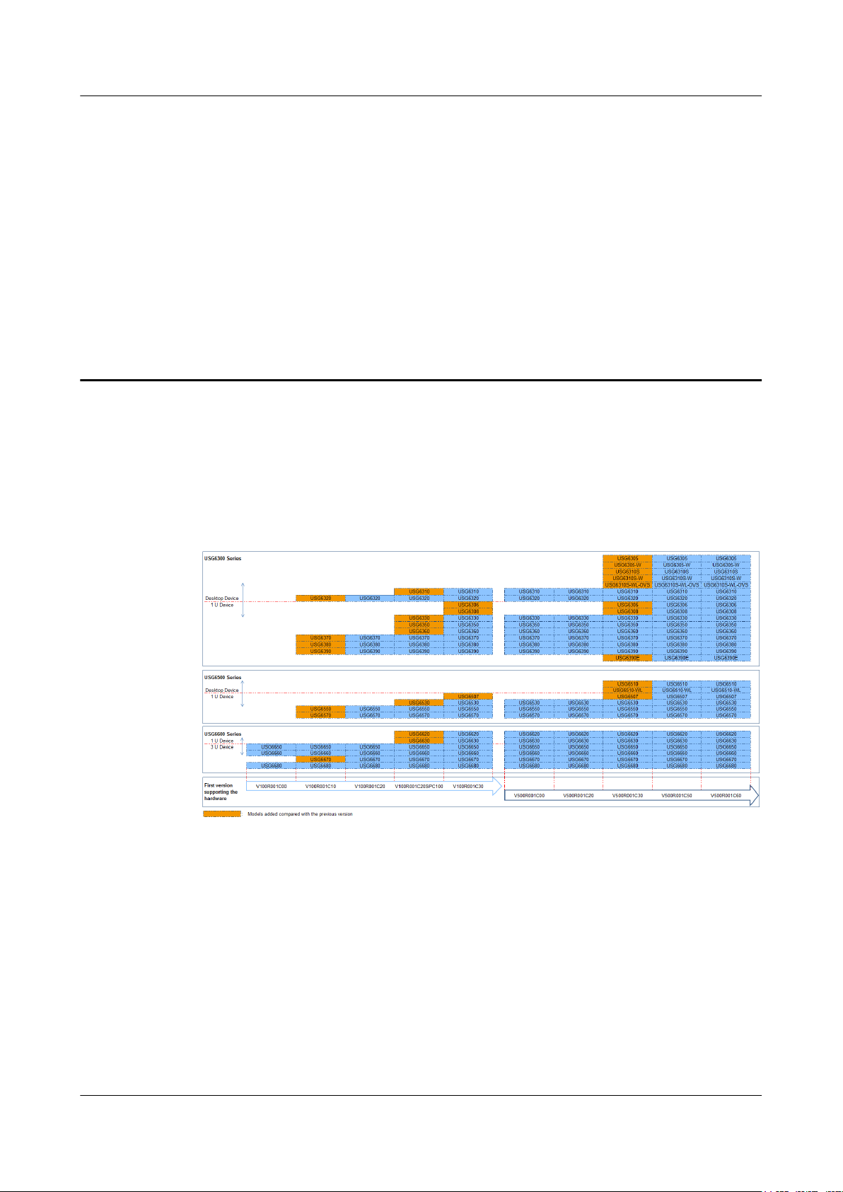
1 Software Versions Compatible with
This section describes software versions compatible with the USG hardware.
The USG has its software versions constantly updated and optimized ever since its launch.
Figure 1-1 displays software versions compatible with the USG and version evolution.
1 Software Versions Compatible with Hardware
Hardware
Figure 1-1 Software Versions Compatible with Hardware
Issue 08 (2017-06-30) Huawei Proprietary and Confidential
Copyright © Huawei Technologies Co., Ltd.
1
Front view
Rear view
Secospace USG6000
02
13
RST
micro
SD
12V ; 2A
CONSOLE
PWR SYS ALM USB
micro
SD
Secospace USG6000
0123
ETH
XXXXXXXXXXXXXXXXXXXXXXXXXXX
HUAWEI USG6000 Series
Hardware Guide
2.1 USG6300 Product Series
The USG6300 product series includes USG6305/6305-W/6310S/6310S-W/6310S-WL-OVS/
6310/6320/6306/6308/6330/6350/6360/6370/6380/6390/6390E. These models are 1 U
devices with an integrated structure and fit into a 19-inch standard cabinet. A larger model
number indicates a higher performance.
2 Hardware Overview
2 Hardware Overview
2.1.1 USG6305
The USG6305 is a 1-U desktop device that provides fixed ports and does not support
expansion.
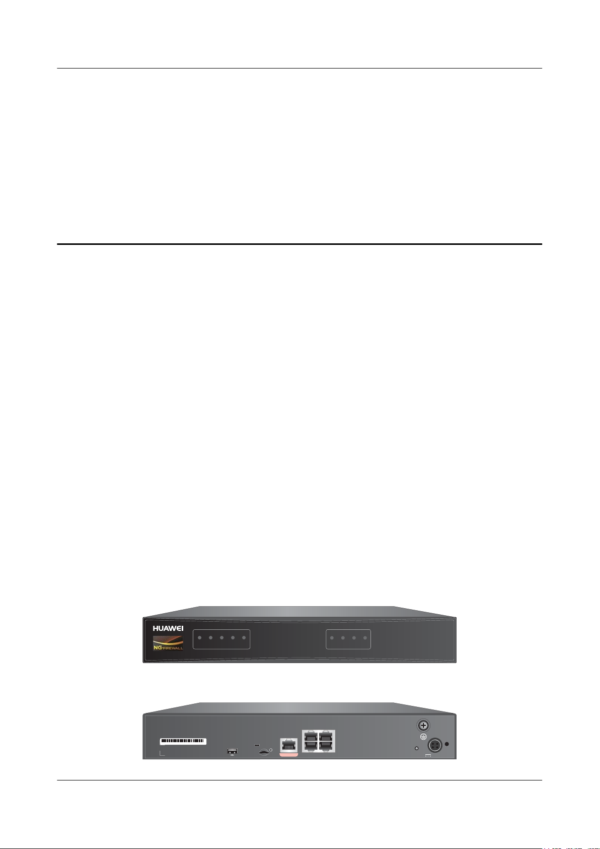
2.1.1.1 Device Overview
The USG6305 is a 1-U desktop device with an integrated structure. The device uses natural
cooling, provides fixed ports, and uses an external power adapter to supply power. The device
does not support port expansion.
Appearance
Figure 2-1 illustrates the appearance of the USG6305.
Figure 2-1 Appearance of USG6305
Issue 08 (2017-06-30) Huawei Proprietary and Confidential
Copyright © Huawei Technologies Co., Ltd.
2
PWR SYS ALM USB
micro
SD
Secospace USG6000
0123
ETH
PWR SYS ALM USB
micro
SD
0123
ETH
Interface status indicators
System status indicators
HUAWEI USG6000 Series
Hardware Guide
Ports
The USG6305 provides the following fixed ports:
l 1 console port (RJ45)
l 1 USB 2.0 port
l 1 micro SD card slot
l 4 10/100/1000M autosensing Ethernet electrical ports
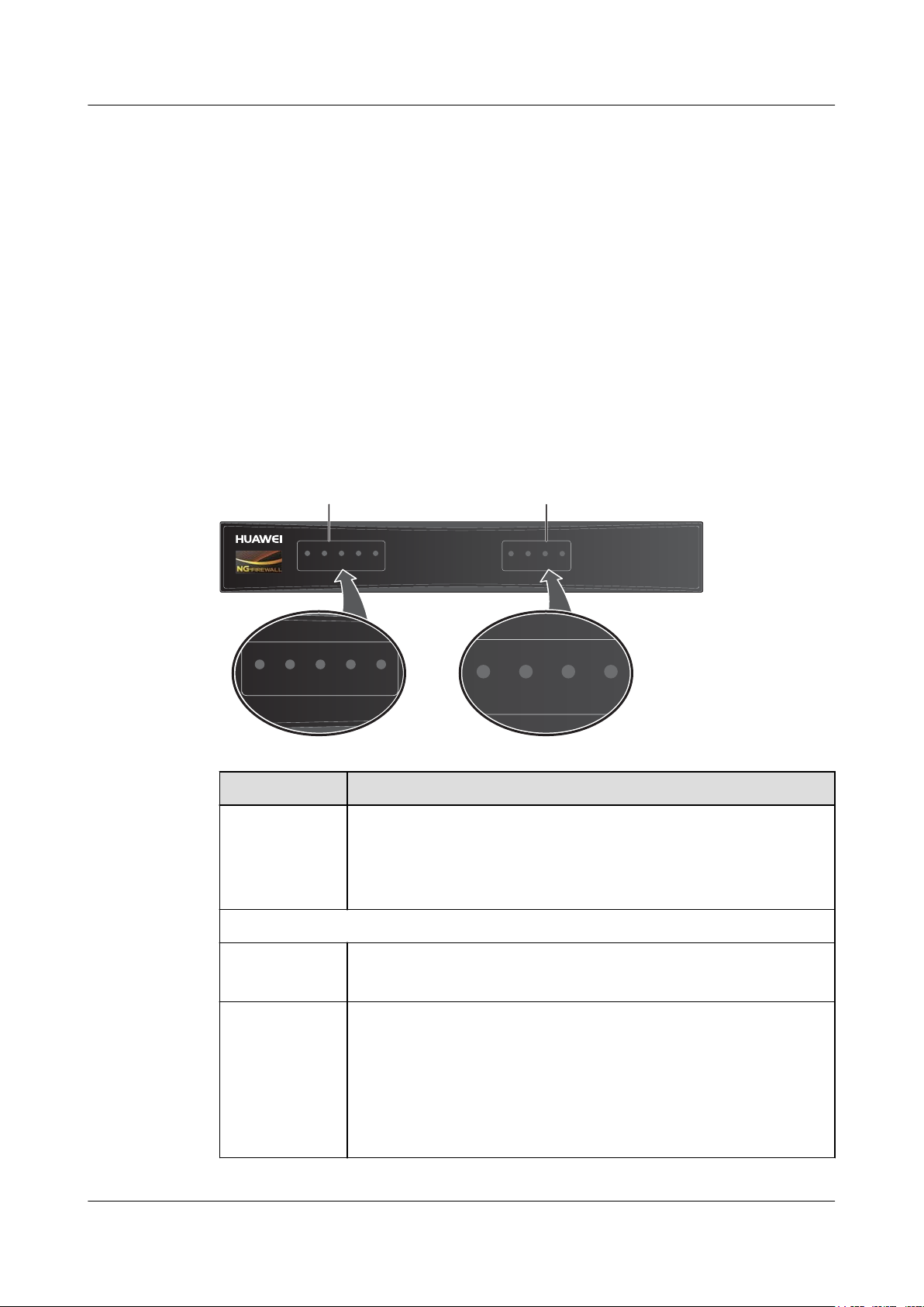
2.1.1.2 Front Panel
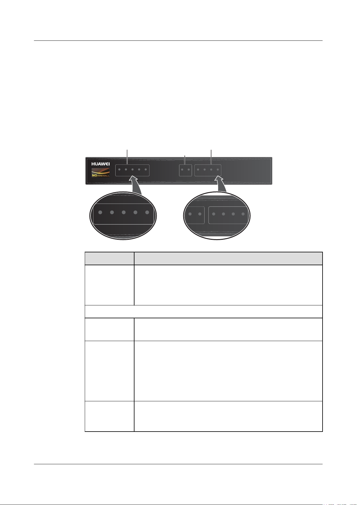
The USG6305 front panel provides system and port status indicators.
Figure 2-2 illustrates the front panel of the USG6305.
Figure 2-2 USG6305 front panel
2 Hardware Overview
Issue 08 (2017-06-30) Huawei Proprietary and Confidential
Name
Interface status
indicators 0 to 3
(green)
Description
l Steady on: The link is connected.
l Blink eight times every second (8 Hz): Data is being sent or
received.
l Off: The link is disconnected.
System status indicators
PWR indicator
(green)
SYS indicator
(green)
l Steady on: The power module works properly.
l Off: The power module is faulty or the power cable is disconnected.
l Steady on: The system is being powered on or restarted.
l Blink every two seconds (0.5 Hz): The system is running normally.
l Blink twice every second (2 Hz): The system is starting.
l Blink eight times every second (8 Hz): The system software or
configuration file is being upgraded.
l Off: The system is faulty.
Copyright © Huawei Technologies Co., Ltd.
3
Secospace USG6000
02
13
RST
micro
SD
12V ; 2A
CONSOLE
02
13
CONSOLE
SN
XXXXXXXXXXXXXXXXXXXXXXXXXXX
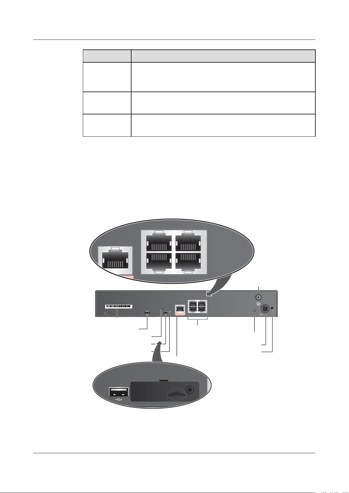
Protective ground
terminal
USB2.0 port
A
nti-theft locating hole
Micro SD card slot
RST button
10/100/1000M
autosensing
Ethernet
electrical ports
Console port
Power receptacle
Clip hole
micro
SD
C
Anti-theft mounting hole
HUAWEI USG6000 Series
Hardware Guide
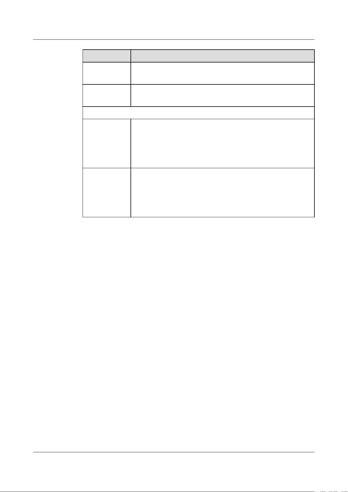
Name Description
2 Hardware Overview
ALM indicator
(red)
USB indicator
(green)
Micro SD
indicator (green)
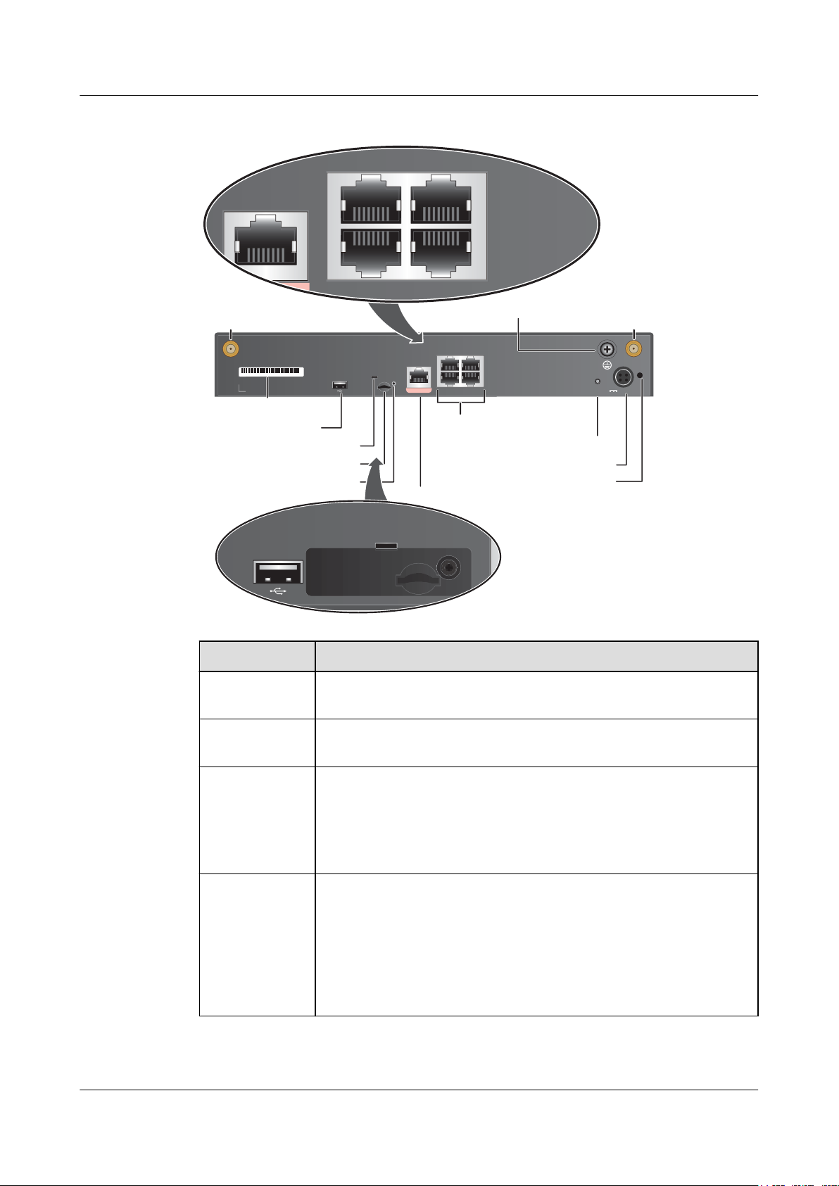
2.1.1.3 Rear Panel
The rear panel of the USG6305 provides fixed ports, a protective ground terminal, RST
button, and power socket.
Figure 2-3 illustrates the rear panel of the USG6305.
Figure 2-3 USG6305 rear panel
l Steady on: The system is faulty. For example, the power-on self test
(POST), power voltage, or temperature is abnormal.
l Off: The system is running normally.
l Steady on: The USB 2.0 port is connected.
l Off: The USB 2.0 port is disconnected.
l Steady on: The micro SD card is present.
l Off: The micro SD card is not detected.
Issue 08 (2017-06-30) Huawei Proprietary and Confidential
Copyright © Huawei Technologies Co., Ltd.
4
HUAWEI USG6000 Series
Hardware Guide
Name Description
SN The serial number that uniquely identifies the device. When applying
2 Hardware Overview
for a license file, you must provide the SN of the device.
USB 2.0 port
l USB ports allow you to insert USB devices for system software
upgrades. For details on upgrades through USB devices, refer to the
Upgrade Guide delivered with the device.
l USB ports allow you to insert 4G LTE data cards. For details on the
4G LTE data cards, refer to 2.6 4G LTE Data Card.
Micro SD card
slot
The micro SD card slot allows you to insert a micro SD card to record
logs and reports in real time. The micro SD card is optional. You can
purchase one (BOM code: 06010308, model: SDSDQAE-064G,
capacity: 64GB, dimensions (H x W x D): 1 mm x 15.00 mm x 11.00
mm) from Huawei if needed.
You are advised to install an anti-theft board delivered with the device
to protect the micro SD card.
Console port
(RJ45)
Console ports allow you to locally connect a PC to the device.
You can use a console cable to connect the console port (RJ45) on the
device to the COM port on your PC and use a serial port terminal
program on your PC to access, configure, and manage the device.
0 to 3 (RJ45) 4 10/100/1000M autosensing Ethernet electrical ports, numbered from
GigabitEthernet 0/0/0 to GigabitEthernet 0/0/3.
GigabitEthernet 0/0/0 is an inband management port and its default IP
address is 192.168.0.1. After this port is connected to your PC through
network cables, you can log in to the device using Telnet, STelnet, or
web UI to configure or manage the device.
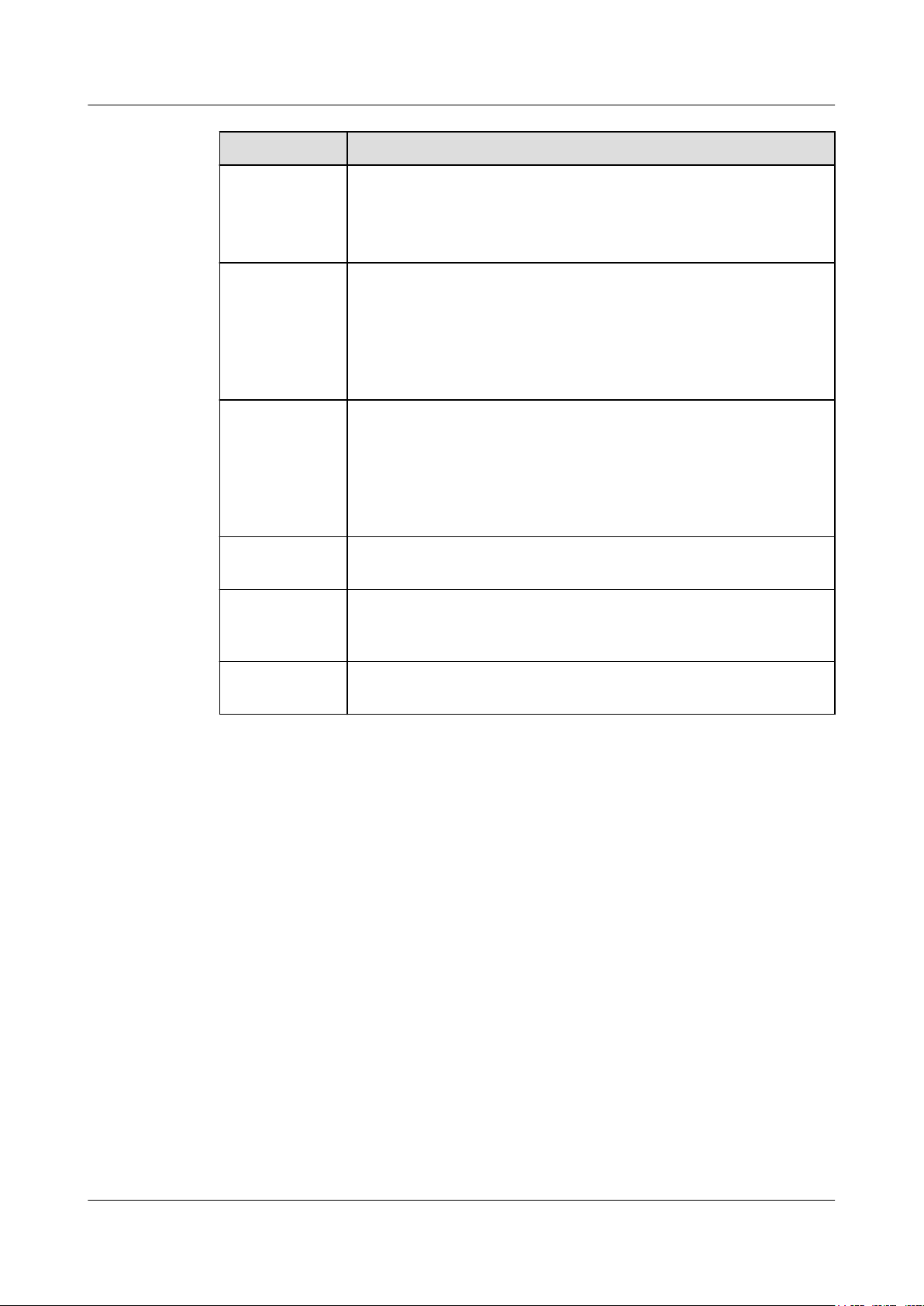
RST button To restart the device, press the RST button. Ensure that the running
Power
receptacle
Protective
ground terminal
Clip hole The hole is used to install the power cable clip, which is used to bind
2.1.1.4 Power Supply System
The USG6305 does not have a built-in power module and requires an external 24W power
adapter.
configuration is saved before pressing the RST button.
The RST button can also be used to restore the default settings. To do
so, press and hold down the RST button and power on the device. Three
to five seconds later, when the SYS and ALM indicators on the front
panel are both blinking, release the RST button.
Connects to the 4-pin plug of the power adapter.
The M4 OT terminal connects the PGND cable to the ground point of
the cabinet, workbench, or wall, or the ground bar in an equipment
room.
and fix the power cable.
Issue 08 (2017-06-30) Huawei Proprietary and Confidential
Copyright © Huawei Technologies Co., Ltd.
5
HUAWEI USG6000 Series
Hardware Guide
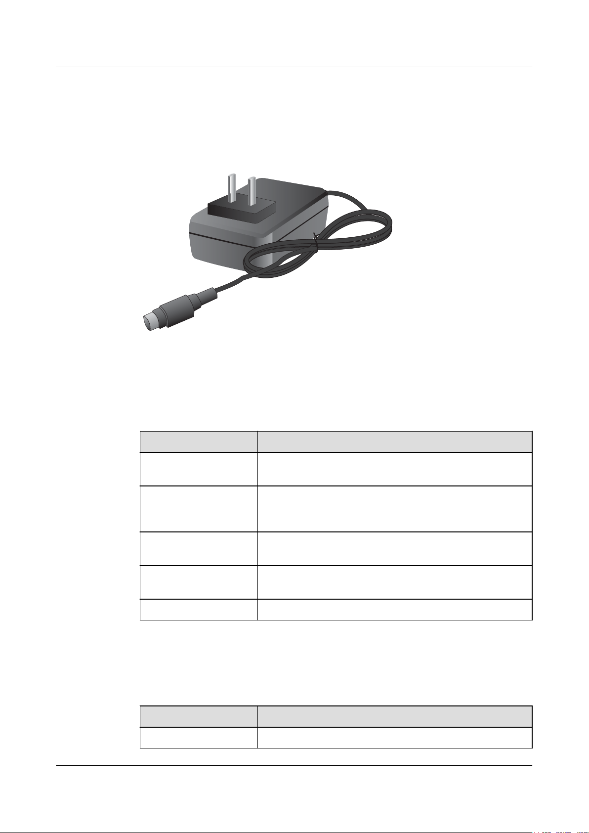
24W Power Adapter
The 24W power adapter converts AC power to DC power for the device. Figure 2-4
illustrates the appearance of the power adapter.
Figure 2-4 Appearance of the 24W power adapter
2 Hardware Overview
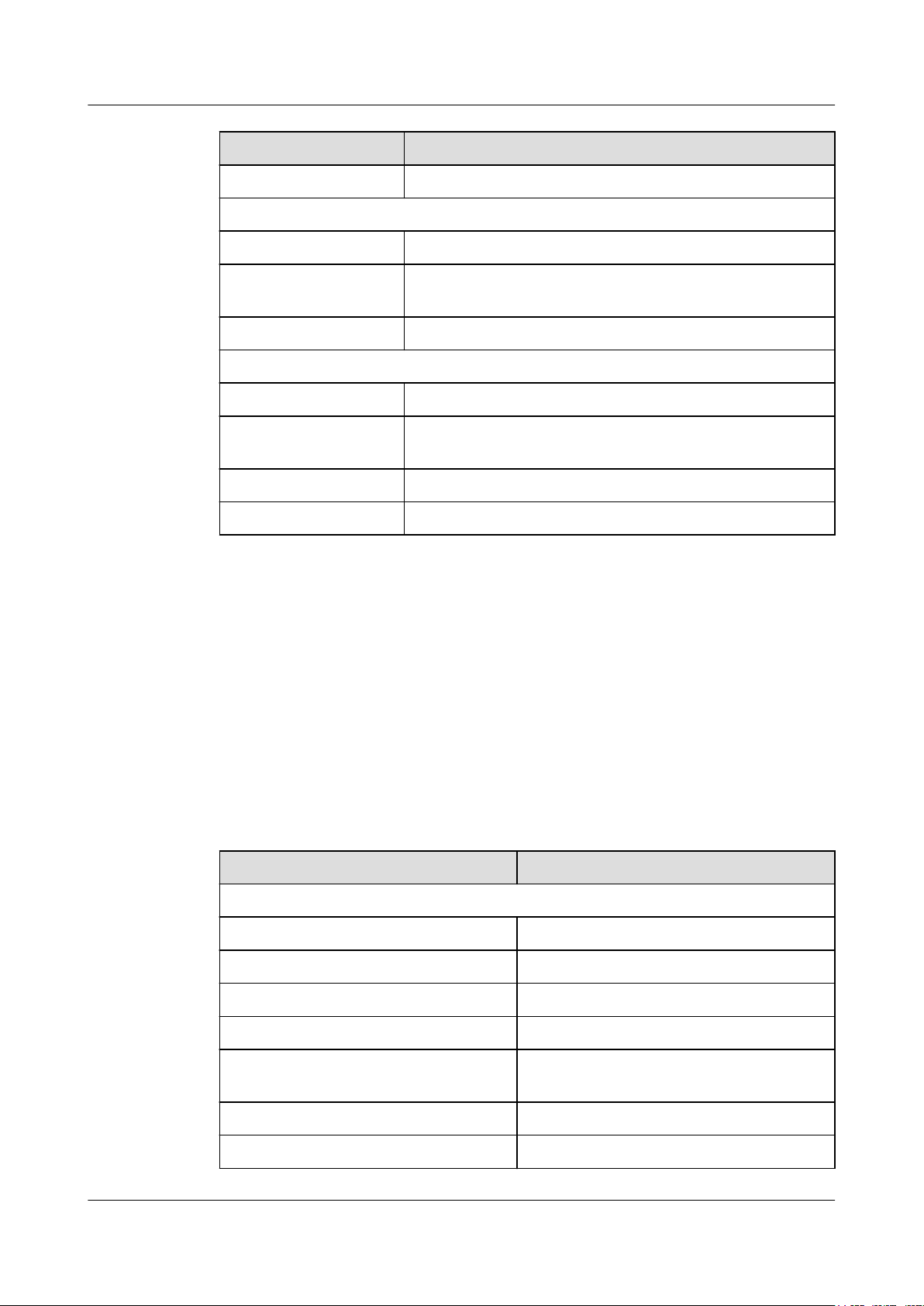
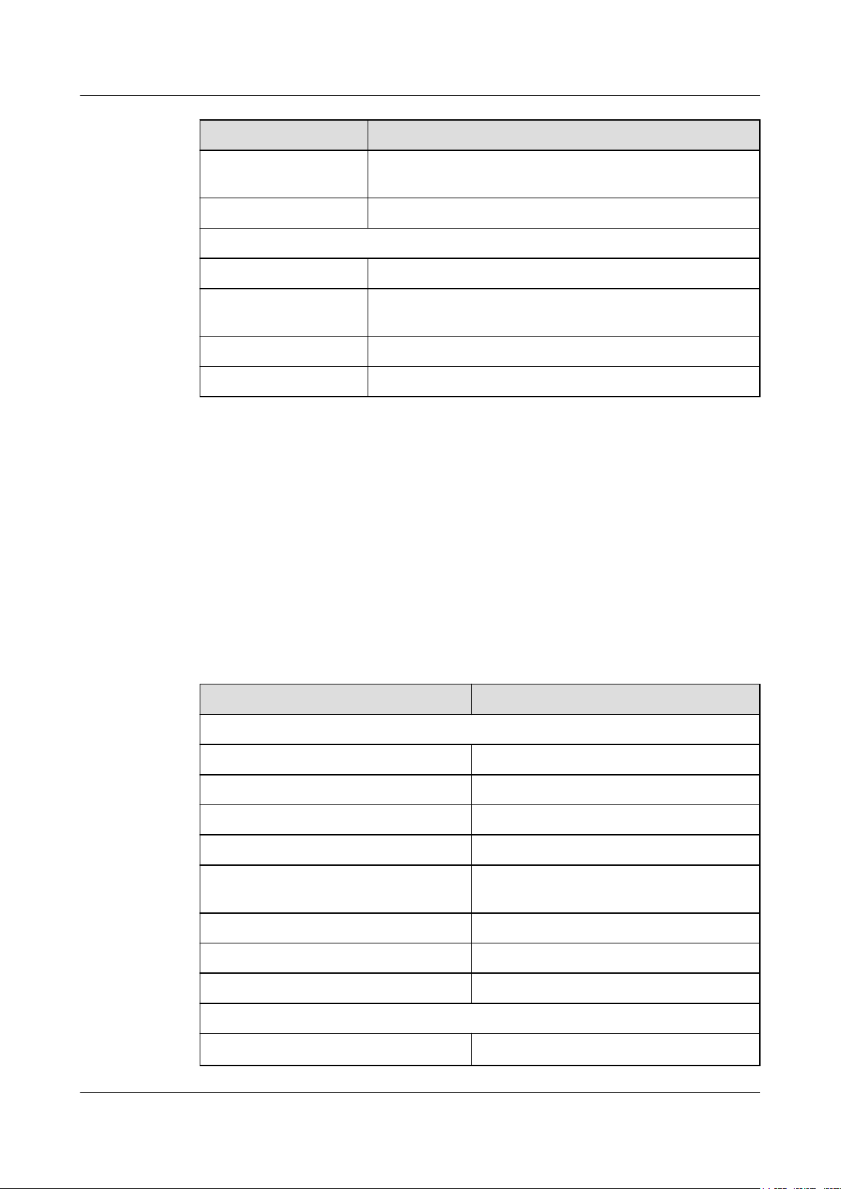
Table 2-1 lists the functions of the 24W power adapter.
Table 2-1 Functions of the 24W power adapter
Item
Input overcurrent
protection
Output current limiting
protection
Description
Stops power output and does not automatically restore power
output after the input current becomes normal.
Intermittently provides output and automatically restores
normal output after the output current falls within a normal
range.
Output overvoltage
protection
Output short circuit
protection
Intermittently stops output and automatically restores output
after the overvoltage condition is removed.
Intermittently provides output and automatically restores
normal output after the output short circuit is removed.
Heat dissipation The power adapter does not have fans and uses natural cooling.
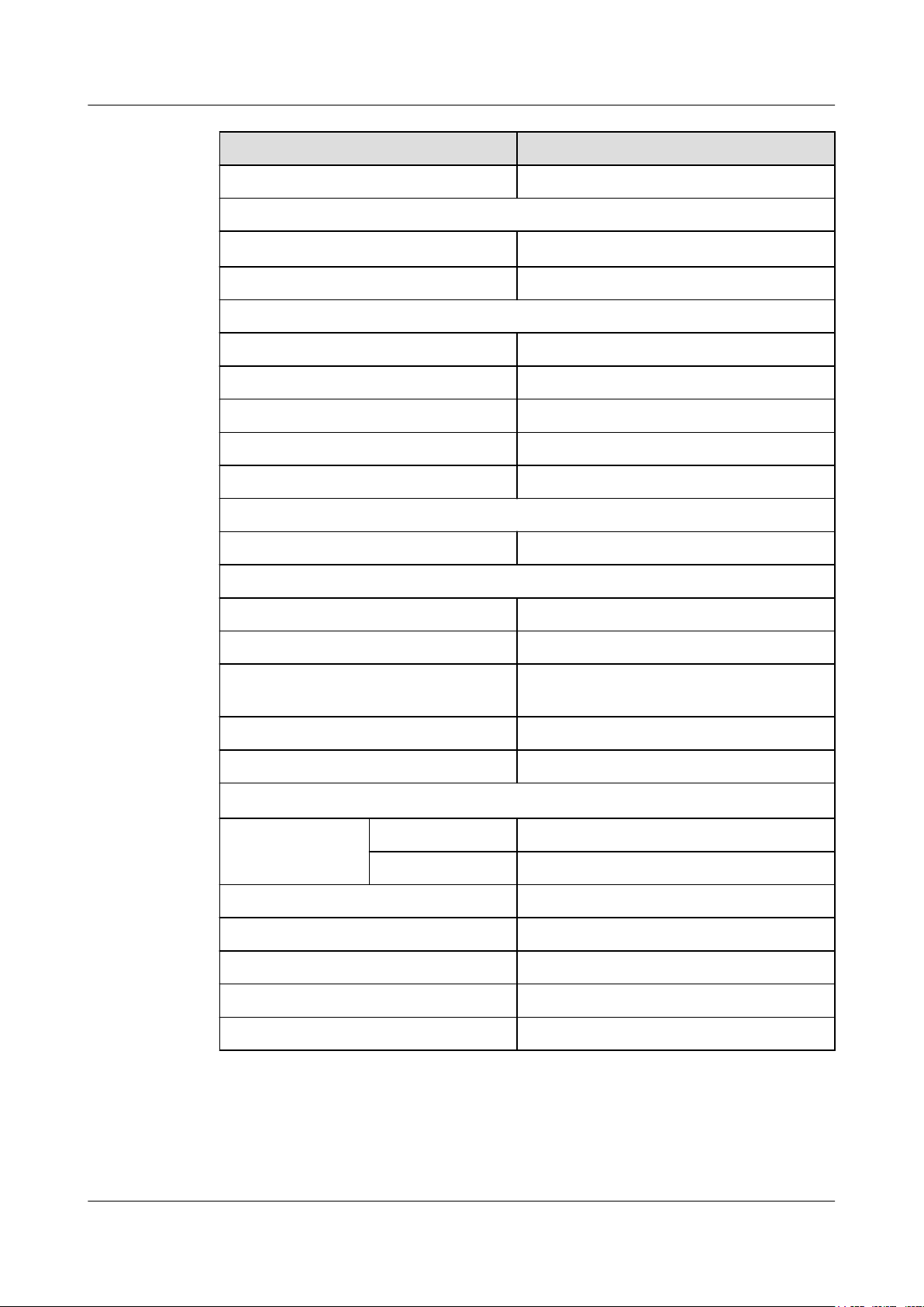
Table 2-2 lists the technical specifications of the 24W power adapter.
Table 2-2 Technical specifications of the 24W power adapter
Item
Description
Dimensions (H x W x D) 28 mm x 51 mm x 86 mm
Issue 08 (2017-06-30) Huawei Proprietary and Confidential
Copyright © Huawei Technologies Co., Ltd.
6
HUAWEI USG6000 Series
Hardware Guide
Item Description
Weight 0.15 kg
Input
Rated input voltage range 100 V AC to 240 V AC (50 Hz/60 Hz)
2 Hardware Overview
Maximum input voltage
range
Maximum input current 0.8 A
Output
Rated output voltage 12 V DC
Maximum output voltage
range
Maximum output current 2 A
Maximum output power 24 W
2.1.1.5 Heat Dissipation System
The USG6305 does not have fans and uses natural cooling.
2.1.1.6 Technical Specifications
This section describes the dimensions, weight, and power and environment specifications of
the USG6305.
90 V AC to 264 V AC (47 Hz to 63 Hz)
11.4 V DC to 12.6 V DC
Table 2-3 lists the technical specifications of the USG6305.
Table 2-3 USG6305 Technical Specifications
Item
System specifications
CPU Multi-core 1.0 GHz processor
Memory DDR3 1 GB
Flash 32 MB
NAND Flash 512 MB
Micro SD card Optional. Purchase one 64-GB micro SD card
Hard disk Not supported
SPUB (the service engine) Not supported
Issue 08 (2017-06-30) Huawei Proprietary and Confidential
Copyright © Huawei Technologies Co., Ltd.
Description
from Huawei as required.
7
HUAWEI USG6000 Series
Hardware Guide
Item Description
4G LTE Data Card Supported
Dimensions and weight
2 Hardware Overview
Dimensions (Hb x Wa x D)
44 mm x 300 mm x 220 mm
Weight 1.55 kg
Power specifications
AC power Supported (external AC power adapter)
Rated input voltage (AC) 100 V to 240 V, 50 Hz/60 Hz
Maximum input voltage (AC) 90 V to 264 V, 47 Hz to 63 Hz
Maximum input current 0.8 A
Maximum output power 24 W
Heat dissipation
Fan module Has no fan and uses natural cooling.
Port density
Console port 1 (RJ45)
USB 2.0 port 1
Mandatory service ports 4 10/100/1000M autosensing Ethernet
electrical ports
Micro SD card slot 1
Expansion slot None
Environment specifications
c
System reliability MTBF (year) 14.08
MTTR (hour) 1
Long term operating temperature 0°C to 45°C
Storage temperature -40°C to 70°C
Operating relative humidity 5% RH to 95% RH, non-condensing
Storage relative humidity 5% RH to 95% RH, non-condensing
Altitude 5,000 m
Issue 08 (2017-06-30) Huawei Proprietary and Confidential
Copyright © Huawei Technologies Co., Ltd.
8
Rear view
PWR SYS ALM USB
micro
SD
Secospace USG6000
0123
ETH
2.4G
WLAN
5G
Secospace USG6000
02
13
RST
micro
SD
12V ; 2A
CONSOLE
WiFi 0
WiFi 1
XXXXXXXXXXXXXXXXXXXXXXXXXXX
Front view
HUAWEI USG6000 Series
Hardware Guide
Item Description
NOTE
l a. The width does not include the size of mounting ears.
l b. The height is 1 U (1 U = 1.75 inches, or about 44.45 mm), which is a height unit defined in
International Electrotechnical Commission (IEC) 60297 standards.
l c. Temperature and humidity are measured 1.5 m above the floor and 0.4 m in front of the rack when
no protection plate exists before or after the rack.
2.1.2 USG6305-W
The USG6305-W is a 1-U desktop device that provides fixed ports, supports WLAN access,
and does not support expansion.
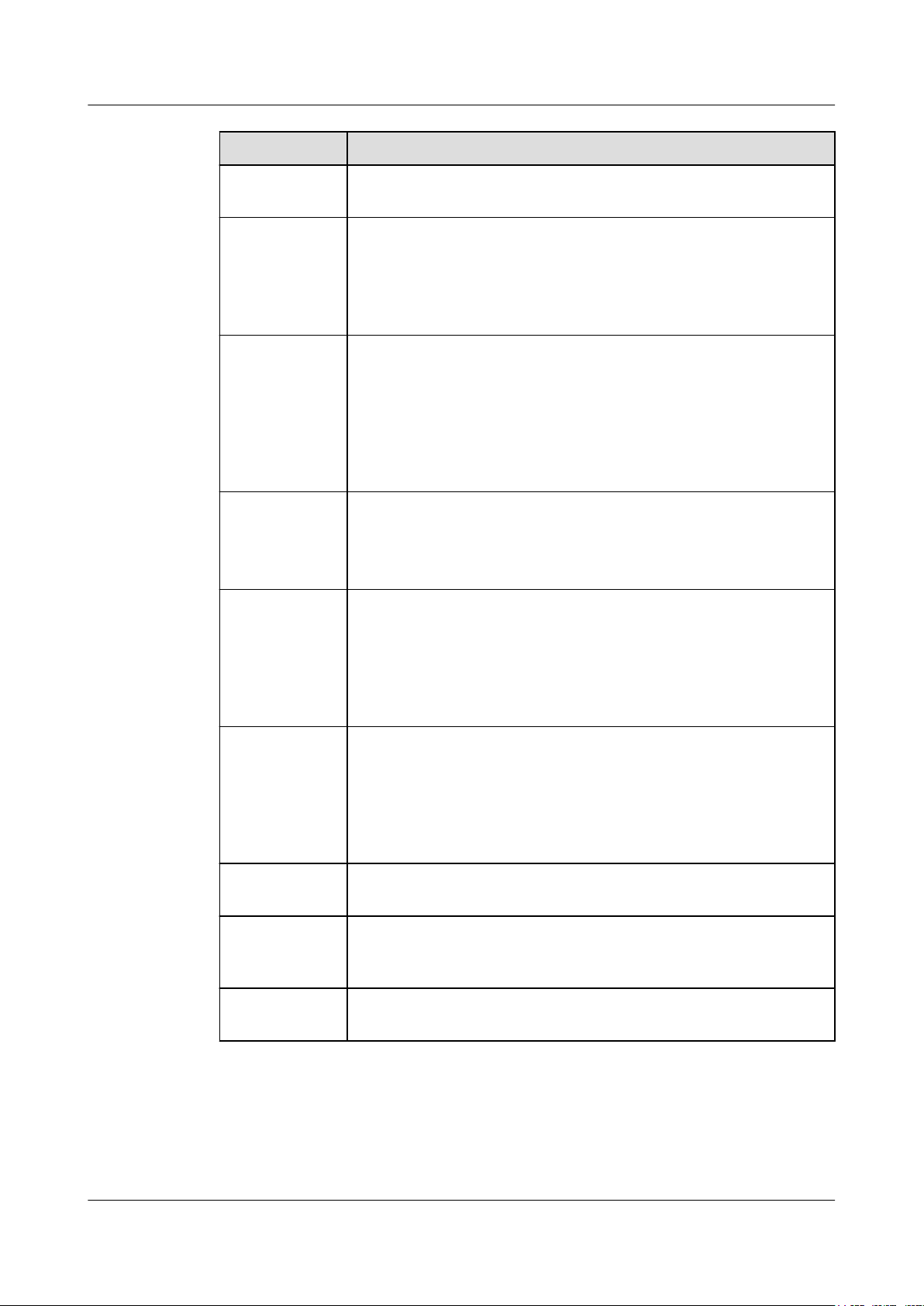
2.1.2.1 Device Overview
The USG6305-W is a 1-U desktop device with an integrated structure. The device uses
natural cooling, provides fixed ports, supports WLAN access, and uses an external power
adapter to supply power. The device does not support port expansion.
2 Hardware Overview
Appearance
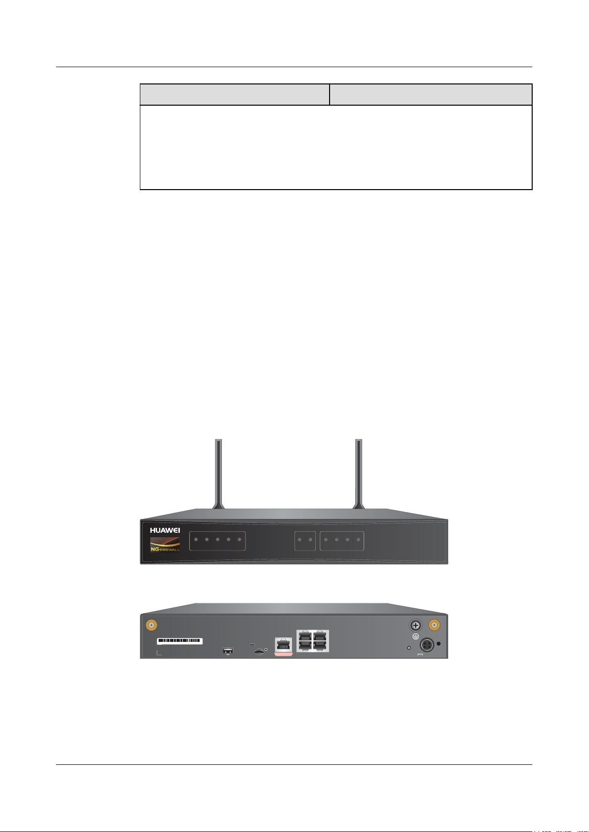
Figure 2-5 illustrates the appearance of the USG6305-W.
Figure 2-5 Appearance of USG6305-W
Ports
l 1 console port (RJ45)
l 1 USB 2.0 port
Issue 08 (2017-06-30) Huawei Proprietary and Confidential
The USG6305-W provides the following fixed ports:
Copyright © Huawei Technologies Co., Ltd.
9
PWR SYS ALM USB
micro
SD
Secospace USG6000
0123
ETH
2.4G
WLAN
5G
PWR SYS ALM USB
micro
SD
0123
ETH
2.4G
WLAN
5G
Interface status indicators
WiFi status indicators
System status indicators
HUAWEI USG6000 Series
Hardware Guide
l 1 micro SD card slot
l 2 WiFi antenna connectors (IEEE 802.11 a/b/g/n/ac)
l 4 10/100/1000M autosensing Ethernet electrical ports
2.1.2.2 Front Panel
The USG6305-W front panel provides system, WiFi and port status indicators.
Figure 2-6 illustrates the front panel of the USG6305-W.
Figure 2-6 USG6305-W front panel
2 Hardware Overview
Name
Interface status
indicators 0 to 3
(green)
Description
l Steady on: The link is connected.
l Blink eight times every second (8 Hz): Data is being sent or
received.
l Off: The link is disconnected.
System status indicators
PWR indicator
(green)
SYS indicator
(green)
l Steady on: The power module works properly.
l Off: The power module is faulty or the power cable is disconnected.
l Steady on: The system is being powered on or restarted.
l Blink every two seconds (0.5 Hz): The system is running normally.
l Blink twice every second (2 Hz): The system is starting.
l Blink eight times every second (8 Hz): The system software or
configuration file is being upgraded.
l Off: The system is faulty.
ALM indicator
(red)
l Steady on: The system is faulty. For example, the power-on self test
(POST), power voltage, or temperature is abnormal.
l Off: The system is running normally.
Issue 08 (2017-06-30) Huawei Proprietary and Confidential
10
Copyright © Huawei Technologies Co., Ltd.
HUAWEI USG6000 Series
Hardware Guide
Name Description
2 Hardware Overview
USB indicator
(green)
Micro SD
indicator (green)
WiFi status indicators
WLAN 2.4G
indicator (green)
WLAN 5G
indicator (green)
l Steady on: The USB 2.0 port is connected.
l Off: The USB 2.0 port is disconnected.
l Steady on: The micro SD card is present.
l Off: The micro SD card is not detected.
l Steady on: The channel is enabled, the SSID is allocated, but no
device is connecting.
l Blink every two seconds (0.5 Hz): The device is accessing WiFi.
l Blink twice every second (2 Hz): Data is being sent or received.
l Off: The channel is disabled, and the SSID is not allocated.
l Steady on: The channel is enabled, the SSID is allocated, but no
device is connecting.
l Blink every two seconds (0.5 Hz): The device is accessing WiFi.
l Blink twice every second (2 Hz): Data is being sent or received.
l Off: The channel is disabled, and the SSID is not allocated.
2.1.2.3 Rear Panel
The rear panel of the USG6305-W provides fixed ports, a protective ground terminal, RST
button, and power socket.
Figure 2-7 illustrates the rear panel of the USG6305-W.
Issue 08 (2017-06-30) Huawei Proprietary and Confidential
Copyright © Huawei Technologies Co., Ltd.
11
Secospace USG6000
02
13
RST
micro
SD
12V ; 2A
CONSOLE
WiFi 0
WiFi 1
XXXXXXXXXXXXXXXXXXXXXXXXXXX
02
13
CONSOLE
SN
Power receptacle
Clip hole
RST button
10/100/1000M
autosensing
Ethernet
electrical ports
Anti-theft locating hole
A
nti-theft mounting hole
Console port
WiFi antenna
connectors
WiFi antenna
connectors
Protective ground
terminal
micro
SD
C
USB2.0 port
Micro SD card slot
HUAWEI USG6000 Series
Hardware Guide
Figure 2-7 USG6305-W rear panel
2 Hardware Overview
Name Description
WiFi antenna
connector
SN The serial number that uniquely identifies the device. When applying
USB 2.0 port
Micro SD card
slot
Connect to the WiFi antennas to receive or send data in WLAN
network. For details, see A.1.9 WiFi Antenna.
for a license file, you must provide the SN of the device.
l USB ports allow you to insert USB devices for system software
upgrades. For details on upgrades through USB devices, refer to the
Upgrade Guide delivered with the device.
l USB ports allow you to insert 4G LTE data cards. For details on the
4G LTE data cards, refer to 2.6 4G LTE Data Card.
The micro SD card slot allows you to insert a micro SD card to record
logs and reports in real time. The micro SD card is optional. You can
purchase one (BOM code: 06010308, model: SDSDQAE-064G,
capacity: 64GB, dimensions (H x W x D): 1 mm x 15.00 mm x 11.00
mm) from Huawei if needed.
You are advised to install an anti-theft board delivered with the device
to protect the micro SD card.
Issue 08 (2017-06-30) Huawei Proprietary and Confidential
12
Copyright © Huawei Technologies Co., Ltd.
HUAWEI USG6000 Series
Hardware Guide
Name Description
2 Hardware Overview
Console port
(RJ45)
0 to 3 (RJ45) 4 10/100/1000M autosensing Ethernet electrical ports, numbered from
RST button To restart the device, press the RST button. Ensure that the running
Power
receptacle
Protective
ground terminal
Console ports allow you to locally connect a PC to the device.
You can use a console cable to connect the console port (RJ45) on the
device to the COM port on your PC and use a serial port terminal
program on your PC to access, configure, and manage the device.
GigabitEthernet 0/0/0 to GigabitEthernet 0/0/3.
GigabitEthernet 0/0/0 is an inband management port and its default IP
address is 192.168.0.1. After this port is connected to your PC through
network cables, you can log in to the device using Telnet, STelnet, or
web UI to configure or manage the device.
configuration is saved before pressing the RST button.
The RST button can also be used to restore the default settings. To do
so, press and hold down the RST button and power on the device. Three
to five seconds later, when the SYS and ALM indicators on the front
panel are both blinking, release the RST button.
Connects to the 4-pin plug of the power adapter.
The M4 OT terminal connects the PGND cable to the ground point of
the cabinet, workbench, or wall, or the ground bar in an equipment
room.
Clip hole The hole is used to install the power cable clip, which is used to bind
2.1.2.4 Power Supply System
The USG6305-W does not have a built-in power module and requires an external 24W power
adapter.
24W Power Adapter
The 24W power adapter converts AC power to DC power for the device. Figure 2-8
illustrates the appearance of the power adapter.
and fix the power cable.
Issue 08 (2017-06-30) Huawei Proprietary and Confidential
Copyright © Huawei Technologies Co., Ltd.
13

HUAWEI USG6000 Series
Hardware Guide
Figure 2-8 Appearance of the 24W power adapter
Table 2-4 lists the functions of the 24W power adapter.
2 Hardware Overview
Table 2-4 Functions of the 24W power adapter
Item
Input overcurrent
protection
Output current limiting
protection
Description
Stops power output and does not automatically restore power
output after the input current becomes normal.
Intermittently provides output and automatically restores
normal output after the output current falls within a normal
range.
Output overvoltage
protection
Output short circuit
protection
Intermittently stops output and automatically restores output
after the overvoltage condition is removed.
Intermittently provides output and automatically restores
normal output after the output short circuit is removed.
Heat dissipation The power adapter does not have fans and uses natural cooling.
Table 2-5 lists the technical specifications of the 24W power adapter.
Table 2-5 Technical specifications of the 24W power adapter
Item
Description
Dimensions (H x W x D) 28 mm x 51 mm x 86 mm
Weight 0.15 kg
Input
Rated input voltage range 100 V AC to 240 V AC (50 Hz/60 Hz)
Issue 08 (2017-06-30) Huawei Proprietary and Confidential
Copyright © Huawei Technologies Co., Ltd.
14
HUAWEI USG6000 Series
Hardware Guide
Item Description
2 Hardware Overview
Maximum input voltage
range
Maximum input current 0.8 A
Output
Rated output voltage 12 V DC
Maximum output voltage
range
Maximum output current 2 A
Maximum output power 24 W
2.1.2.5 Heat Dissipation System
The USG6305-W does not have fans and uses natural cooling.
2.1.2.6 Technical Specifications
This section describes the dimensions, weight, and power and environment specifications of
the USG6305-W.
90 V AC to 264 V AC (47 Hz to 63 Hz)
11.4 V DC to 12.6 V DC
Table 2-6 lists the technical specifications of the USG6305-W.
Table 2-6 USG6305-W Technical Specifications
Item
System specifications
CPU Multi-core 1.0 GHz processor
Memory DDR3 1 GB
Flash 32 MB
NAND Flash 512 MB
Micro SD card Optional. Purchase one 64-GB micro SD card
Hard disk Not supported
SPUB (the service engine) Not supported
4G LTE Data Card Supported
Dimensions and weight
Description
from Huawei as required.
Dimensions (Hb x Wa x D)
Issue 08 (2017-06-30) Huawei Proprietary and Confidential
Copyright © Huawei Technologies Co., Ltd.
44 mm x 300 mm x 220 mm
15

HUAWEI USG6000 Series
Hardware Guide
Item Description
Weight 1.60 kg
Power specifications
AC power Supported (external AC power adapter)
Rated input voltage (AC) 100 V to 240 V, 50 Hz/60 Hz
Maximum input voltage (AC) 90 V to 264 V, 47 Hz to 63 Hz
Maximum input current 0.8 A
Maximum output power 24 W
Heat dissipation
Fan module Has no fan and uses natural cooling.
Port density
Console port 1 (RJ45)
2 Hardware Overview
USB 2.0 port 1
Mandatory service ports
l 4 10/100/1000M autosensing Ethernet
electrical ports
l 2 WiFi antenna connectors
Micro SD card slot 1
Expansion slot None
WiFi access specifications
Wireless standards IEEE 802.11 a/b/g/n/ac
Wireless rate 300 Mbit/s
Frequency bands
l 2.412 GHz to 2.472 GHz
l 5.18 GHz to 5.825 GHz
Maximum transmit power
c
l 2.4 GHz: 15 dBm
l 5 GHz: 20 dBm
Environment specifications
d
System reliability MTBF (year) 13.8
MTTR (hour) 1
Long term operating temperature 0°C to 45°C
Storage temperature -40°C to 70°C
Operating relative humidity 5% RH to 95% RH, non-condensing
Storage relative humidity 5% RH to 95% RH, non-condensing
Issue 08 (2017-06-30) Huawei Proprietary and Confidential
Copyright © Huawei Technologies Co., Ltd.
16
 Loading...