

Huawei UPS5000-E-400 kVA, UPS5000-E-480 kVA, UPS5000-E-360 kVA, UPS5000-E-440 kVA User Manual
Page 1

UPS5000-E-(360 kVA-480 kVA)
User Manual (40 kVA Power
Modules)
Issue
07
Date
2020-01-10
HUAWEI TECHNOLOGIES CO., LTD.
Page 2

Issue 07 (2020-01-10)
Copyright © Huawei Technologies Co., Ltd.
i
Copyright © Huawei Technologies Co., Ltd. 2020 . All rights reserved.
No part of this document may be reproduced or transmitted in any form or by any means without prior
written consent of Huawei Technologies Co., Ltd.
Trademarks and Permissions
and other Huawei trademarks are trademarks of Huawei Technologies Co., Ltd.
All other trademarks and trade names mentioned in this document are the property of their respective
holders.
Notice
The purchased products, services and features are stipulated by the contract made between Huawei and
the customer. All or part of the products, services and features described in this document may not be
within the purchase scope or the usage scope. Unless otherwise specified in the contract, all statements,
information, and recommendations in this document are provided "AS IS" without warranties, guarantees
or representations of any kind, either express or implied.
The information in this document is subject to change without notice. Every effort has been made in the
preparation of this document to ensure accuracy of the contents, but all statements, information, and
recommendations in this document do not constitute a warranty of any kind, express or implied.
Huawei Technologies Co., Ltd.
Address:
Huawei Industrial Base
Bantian, Longgang
Shenzhen 518129
People's Republic of China
Website:
https://e.huawei.com
Page 3
UPS5000-E-(360 kVA-480 kVA)
User Manual (40 kVA Power Modules)
About This Document
Issue 07 (2020-01-10)
Copyright © Huawei Technologies Co., Ltd.
ii
Purpose
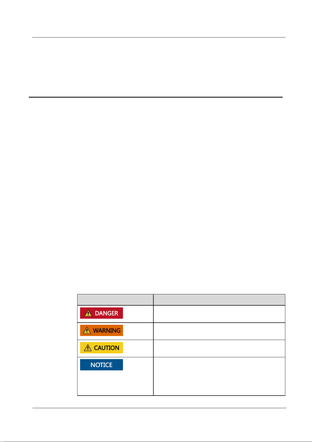
Symbol
Description
Indicates a hazard with a high level of risk which, if not
avoided, will result in death or serious injury.
Indicates a hazard with a medium level of risk which, if
not avoided, could result in death or serious injury.
Indicates a hazard with a low level of risk which, if not
avoided, could result in minor or moderate injury.
Indicates a potentially hazardous situation which, if not
avoided, could result in equipment damage, data loss,
performance deterioration, or unanticipated results.
NOTICE is used to address practices not related to
personal injury.
This document describes the UPS5000-E-(360 kVA-480 kVA) in terms of its features,
performance, working principles, appearance as well as instructions for installation, and
operation and maintenance (O&M).
Intended Audience
This document is intended for:
About This Document
Sales engineers
Technical support engineers
System engineers
Hardware installation engineers
Commissioning engineers
Data configuration engineers
Maintenance engineers
Symbol Conventions
The symbols that may be found in this document are defined as follows.
Page 4

UPS5000-E-(360 kVA-480 kVA)
User Manual (40 kVA Power Modules)
About This Document
Issue 07 (2020-01-10)
Copyright © Huawei Technologies Co., Ltd.
iii
Symbol
Description
Supplements the important information in the main text.
NOTE is used to address information not related to
personal injury, equipment damage, and environment
deterioration.
Change History
Changes between document issues are cumulative. The latest document issue contains all the
changes made in earlier issues.
Issue 07 (2020-01-10)
Added SNMP descriptions to the sections about site configuration.
Added the SNMP V1 and V2 protocol description.
Updated the safety information.
Issue 06 (2017-11-17)
Updated the section "Battery Electrical specifications".
Issue 05 (2017-10-09)
Updated the recommended cable data.
Issue 04 (2017-02-22)
Updated the voltage data of the monitoring interface card and the content of routine
maintenance.
Issue 03 (2016-01-20)
Updated the maximum voltage and current which the monitoring interface card can support,
optimized the dual bus scenario, and updated the routine maintenance.
Issue 02 (2015-08-20)
Deleted V100R001 from the version information.
Issue 01 (2015-04-02)
This is the first release.
Page 5

UPS5000-E-(360 kVA-480 kVA)
User Manual (40 kVA Power Modules)
Contents
Issue 07 (2020-01-10)
Copyright © Huawei Technologies Co., Ltd.
iv
Contents
About This Document ............................................................................................................... ii
1 Safety Information ................................................................................................................... 1
1.1 General Safety ....................................................................................................................................................... 1
1.2 Personnel Requirements ........................................................................................................................................ 4
1.3 Electrical Safety .................................................................................................................................................... 4
1.4 Installation Environment Requirements .................................................................................................................. 6
1.5 Mechanical Safety ................................................................................................................................................. 7
1.6 Device Running Safety .........................................................................................................................................10
1.7 Battery Safety ....................................................................................................................................................... 11
1.8 Others ..................................................................................................................................................................14
2 Overview ................................................................................................................................. 15
2.1 Model Description ................................................................................................................................................15
2.2 Working Principle ................................ ................................................................................................ .................15
2.2.1 Conceptual Diagram ..........................................................................................................................................15
2.2.2 Working Modes .................................................................................................................................................16
2.2.2.1 Normal Mode .................................................................................................................................................16
2.2.2.2 Bypass Mode ..................................................................................................................................................17
2.2.2.3 Battery Mode ..................................................................................................................................................18
2.2.2.4 Maintenance Bypass Mode .............................................................................................................................19
2.2.2.5 ECO Mode .....................................................................................................................................................20
2.3 Product Description ................................ .............................................................................................................. 22
2.3.1 Appearance ........................................................................................................................................................22
2.3.2 Product Structure ............................................................................................................................................... 23
2.4 Control Module ....................................................................................................................................................24
2.4.1 Overview ...........................................................................................................................................................24
2.4.2 ECM .................................................................................................................................................................25
2.4.3 Dry contact card ................................................................................................................................................27
2.4.4 (Optional) Backfeed Protection Card ..................................................................................................................29
2.4.5 (Optional) Dry Contact Extended Card ...............................................................................................................29
2.4.6 Monitoring Interface Card ..................................................................................................................................29
2.5 MDU....................................................................................................................................................................34
2.6 Typical configurations ..........................................................................................................................................36
Page 6

UPS5000-E-(360 kVA-480 kVA)
User Manual (40 kVA Power Modules)
Contents
Issue 07 (2020-01-10)
Copyright © Huawei Technologies Co., Ltd.
v
2.6.1 Single UPS ........................................................................................................................................................36
2.6.2 Parallel System ..................................................................................................................................................36
2.6.3 Dual-Bus System ............................................................................................................................................... 37
2.7 Optional Components ...........................................................................................................................................38
3 Installation .............................................................................................................................. 40
3.1 Installation Preparations .......................................................................................................................................40
3.1.1 Site ....................................................................................................................................................................40
3.1.2 Tools and Instruments ................................................................ ........................................................................42
3.1.3 Power Cables .....................................................................................................................................................44
3.1.4 Unpacking and Checking ................................................................................................ ...................................47
3.1.5 (Optional) Splitting the Power Cabinet and Bypass Cabinet ................................................................................50
3.1.6 Optional) Combining the Power Cabinet and Bypass Cabinet .............................................................................59
3.2 Single UPS Installation .........................................................................................................................................60
3.2.1 Installing a UPS .................................................................................................................................................60
3.2.2 Installing Antiseismic Kits .................................................................................................................................65
3.2.3 Installing an IP21 Component ............................................................................................................................67
3.2.4 (Optional) Installing an Ambient Temperature and Humidity Sensor ...................................................................68
3.2.5 Installing Batteries .............................................................................................................................................68
3.2.6 (Optional) Installing Fuses .................................................................................................................................70
3.2.7 Routing Cables ..................................................................................................................................................73
3.2.7.1 Top Cable Routing ................................................................ ..........................................................................73
3.2.7.2 Bottom Cable Routing ....................................................................................................................................75
3.2.8 Connecting Ground Cables ................................................................................................................................79
3.2.9 Connecting AC Input Power Cables ...................................................................................................................80
3.2.9.1 Single Mains ...................................................................................................................................................80
3.2.9.2 Dual Mains ................................................................ .....................................................................................81
3.2.10 Connecting AC Output Power Cables ...............................................................................................................85
3.2.11 Connecting Battery Cables ...............................................................................................................................85
3.2.12 Remote EPO ....................................................................................................................................................87
3.2.13 Connecting Communications Cables ................................................................................................................88
3.3 Parallel System Installation ................................................................ ...................................................................88
3.3.1 Connecting Power Cables ..................................................................................................................................88
3.3.2 Connecting Signal Cables ..................................................................................................................................92
3.4 Installation Verification .........................................................................................................................................94
4 User Interface .......................................................................................................................... 97
4.1 LCD Interface ......................................................................................................................................................97
4.1.1 LCD ..................................................................................................................................................................97
4.1.2 LCD Menu ........................................................................................................................................................98
4.1.2.1 Menu Hierarchy ..............................................................................................................................................98
4.1.2.2 Initial Startup ..................................................................................................................................................99
4.1.2.3 Main Menu ................................................................ .....................................................................................99
Page 7

UPS5000-E-(360 kVA-480 kVA)
User Manual (40 kVA Power Modules)
Contents
Issue 07 (2020-01-10)
Copyright © Huawei Technologies Co., Ltd.
vi
4.1.3 System Info Screen .......................................................................................................................................... 101
4.1.3.1 Module Data Screen ...................................................................................................................................... 101
4.1.3.2 Runn Info Screen ................................................................ .......................................................................... 102
4.1.3.3 Alarms Screen............................................................................................................................................... 107
4.1.3.4 Settings Screen ............................................................................................................................................. 109
4.1.3.5 Maintenance ................................................................................................................................................. 132
4.1.3.6 About Screen ................................................................................................................................................ 136
4.1.4 System Status Screen ....................................................................................................................................... 137
4.1.5 Common Functions Screen .............................................................................................................................. 137
4.2 WebUI ................................................................................................................................................................ 138
4.2.1 Login............................................................................................................................................................... 138
4.2.2 Monitoring Page .............................................................................................................................................. 140
4.2.2.1 Active Alarms Page ....................................................................................................................................... 141
4.2.2.2 Real-time Data Page ..................................................................................................................................... 142
4.2.2.3 Param. Settings Page ..................................................................................................................................... 142
4.2.2.4 Comm. Config. Page ..................................................................................................................................... 143
4.2.2.5 Control Page ................................................................................................................................................. 143
4.2.3 Query Page ...................................................................................................................................................... 144
4.2.3.1 Historical Alarms Page ................................................................................................................................ .. 144
4.2.3.2 Logs Page ..................................................................................................................................................... 144
4.2.4 Config. Page .................................................................................................................................................... 145
4.2.5 Maint. Page ................................................................ ..................................................................................... 147
5 Operations ............................................................................................................................. 150
5.1 Single UPS Operations ....................................................................................................................................... 150
5.1.1 Powering On and Starting the UPS ................................................................................................................... 150
5.1.2 Shutting Down and Powering Off the UPS ....................................................................................................... 161
5.1.3 Starting the UPS in Battery Mode .................................................................................................................... 164
5.1.4 Transferring to Bypass Mode ........................................................................................................................... 165
5.1.5 Setting ECO Mode........................................................................................................................................... 166
5.1.6 Testing Batteries .............................................................................................................................................. 168
5.1.6.1 Forced Equalized Charging Test .................................................................................................................... 168
5.1.6.2 Shallow Discharge Test ................................................................................................................................. 168
5.1.6.3 Capacity Test ................................................................................................................................................ 170
5.1.6.4 Test Data Download ...................................................................................................................................... 171
5.1.7 Transferring to Maintenance Bypass Mode ....................................................................................................... 172
5.1.8 Transferring from Maintenance Bypass Mode to Normal Mode ........................................................................ 173
5.1.9 Performing EPO .............................................................................................................................................. 174
5.1.10 Clearing the EPO State .................................................................................................................................. 175
5.2 Setting Hibernation Mode ................................................................................................................................... 175
5.2.1 LCD ................................................................................................................................................................ 176
5.2.2 WebUI ............................................................................................................................................................. 177
Page 8

UPS5000-E-(360 kVA-480 kVA)
User Manual (40 kVA Power Modules)
Contents
Issue 07 (2020-01-10)
Copyright © Huawei Technologies Co., Ltd.
vii
5.3 Setting Intelligent Power Mode ........................................................................................................................... 178
5.3.1 LCD ................................................................................................................................................................ 178
5.3.2 WebUI ............................................................................................................................................................. 183
5.3.3 Reused Scenario .............................................................................................................................................. 187
5.3.4 ATS Scenario ................................................................................................................................................... 188
5.4 Parallel System Operations ................................................................................................................................. 189
6 Routine Maintenance ........................................................................................................... 190
6.1 UPS Maintenance ................................................................................................ ............................................... 190
6.1.1 Monthly Maintenance ...................................................................................................................................... 190
6.1.2 Quarterly Maintenance..................................................................................................................................... 191
6.1.3 Annual Maintenance ........................................................................................................................................ 191
6.2 Battery Maintenance ........................................................................................................................................... 192
6.2.1 Precautions for Battery Maintenance ................................................................................................................ 193
6.2.2 Monthly Maintenance ...................................................................................................................................... 193
6.2.3 Quarterly Maintenance..................................................................................................................................... 194
6.2.4 Annual Maintenance ........................................................................................................................................ 195
7 Troubleshooting ................................................................................................................... 196
8 Technical Specifications ...................................................................................................... 198
8.1 hysical Characteristics ........................................................................................................................................ 198
8.2 Environment Features ......................................................................................................................................... 198
8.3 Safety Regulations and EMC ................................ .............................................................................................. 199
8.4 Mains Input Electrical Specifications .................................................................................................................. 199
8.5 Bypass Input Electrical Specifications ................................................................................................................. 200
8.6 Battery Electrical specifications .......................................................................................................................... 200
8.7 Output Electrical Specifications .......................................................................................................................... 201
8.8 System Electrical Specifications ......................................................................................................................... 201
A Menu Hierarchy .................................................................................................................. 202
A.1 Menus on the LCD ............................................................................................................................................ 202
A.2 Menus on the WebUI ......................................................................................................................................... 204
B Alarm List ............................................................................................................................. 220
C Acronyms and Abbreviations ............................................................................................ 229
Page 9

UPS5000-E-(360 kVA-480 kVA)
User Manual (40 kVA Power Modules)
1 Safety Information
Issue 07 (2020-01-10)
Copyright © Huawei Technologies Co., Ltd.
1
1.1 General Safety
Statement
Before installing, operating, and maintaining the equipment, read this document and observe
all the safety instructions on the equipment and in this document.
1 Safety Information
The "NOTICE", "CAUTION", "WARNING", and "DANGER" statements in this document
do not cover all the safety instructions. They are only supplements to the safety instructions.
Huawei will not be liable for any consequence caused by the violation of general safety
requirements or design, production, and usage safety standards.
Ensure that the equipment is used in environments that meet its design specifications.
Otherwise, the equipment may become faulty, and the resulting equipment malfunction,
component damage, personal injuries, or property damage are not covered under the warranty.
Follow local laws and regulations when installing, operating, or maintaining the equipment.
The safety instructions in this document are only supplements to local laws and regulations.
Huawei will not be liable for any consequences of the following circumstances:
Operation beyond the conditions specified in this document
Installation or use in environments which are not specified in relevant international or
national standards
Unauthorized modifications to the product or software code or removal of the product
Failure to follow the operation instructions and safety precautions on the product and in
this document
Equipment damage due to force majeure, such as earthquakes, fire, and storms
Damage caused during transportation by the customer
Storage conditions that do not meet the requirements specified in this document
General Requirements
Do not install, use, or operate outdoor equipment and cables (including but not limited to
moving equipment, operating equipment and cables, inserting connectors to or removing
connectors from signal ports connected to outdoor facilities, working at heights, and
performing outdoor installation) in harsh weather conditions such as lightning, rain,
snow, and level 6 or stronger wind.
Page 10
UPS5000-E-(360 kVA-480 kVA)
User Manual (40 kVA Power Modules)
1 Safety Information
Issue 07 (2020-01-10)
Copyright © Huawei Technologies Co., Ltd.
2
Before installing, operating, or maintaining the equipment, remove any conductive
objects such as watches or metal jewelry like bracelets, bangles, and rings to avoid
electric shock.
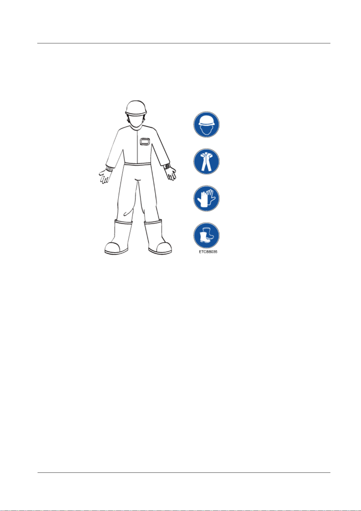
When installing, operating, or maintaining the equipment, wear dedicated protective
gears such as insulation gloves, goggles, and safety clothing, helmet, and shoes, as
shown in the following figure.
Follow the specified procedures for installation, operation, and maintenance.
Before handling a conductor surface or terminal, measure the contact point voltage and
ensure that there is no risk of electric shock.
After installing the equipment, remove idle packing materials such as cartons, foam,
plastics, and cable ties from the equipment area.
In the case of a fire, immediately leave the building or the equipment area, and turn on
the fire alarm bell or make an emergency call. Do not enter the building on fire in any
case.
Do not stop using protective devices. Pay attention to the warnings, cautions, and related
precautionary measures in this document and on the equipment. Promptly replace
warning labels that have worn out.
Keep irrelevant people away from the equipment. Only operators are allowed to access
the equipment.
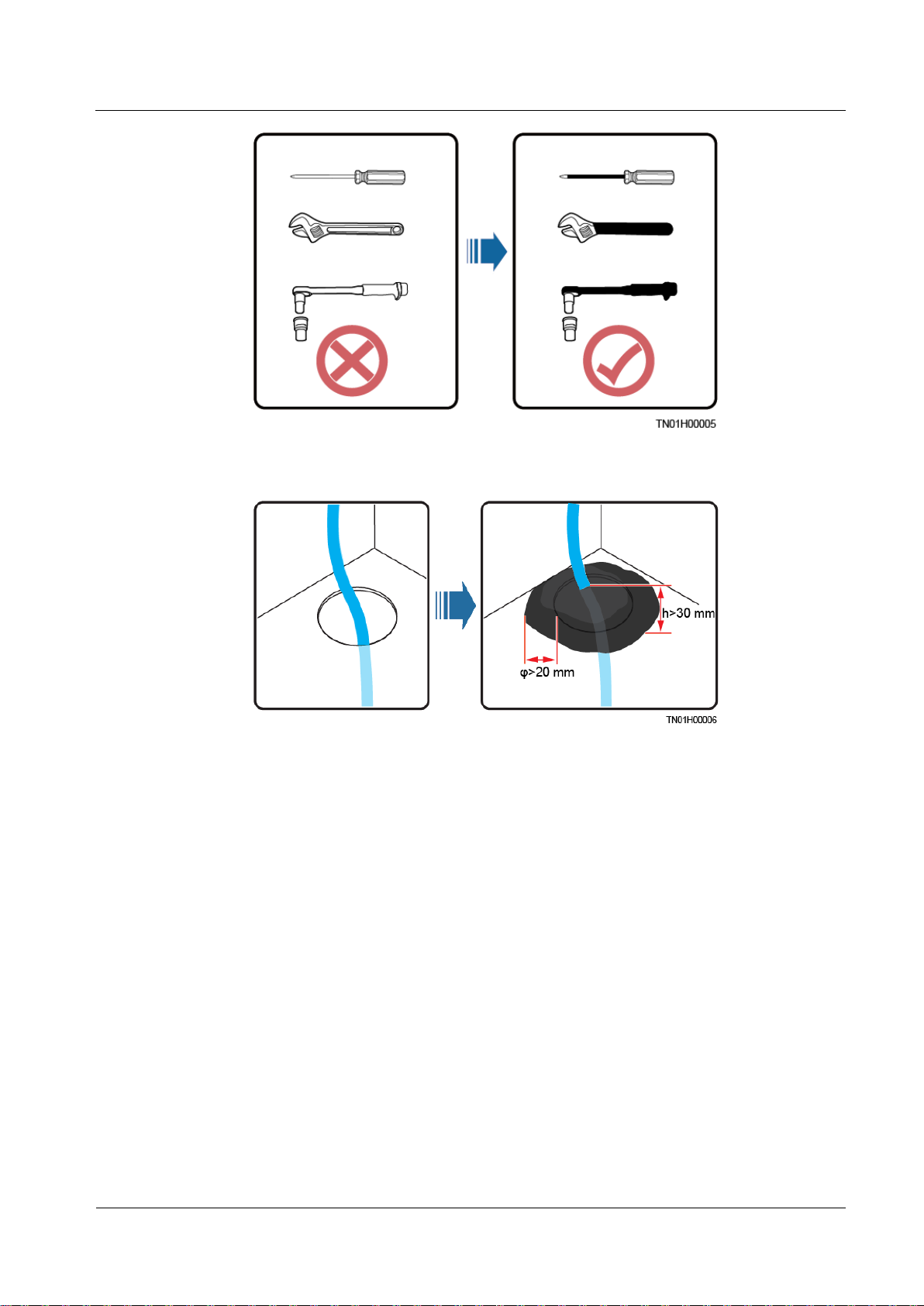
Use insulated tools or tools with insulated handles, as shown in the following figure.
Page 11
UPS5000-E-(360 kVA-480 kVA)
User Manual (40 kVA Power Modules)
1 Safety Information
Issue 07 (2020-01-10)
Copyright © Huawei Technologies Co., Ltd.
3
All cable holes should be sealed. Seal the used cable holes with firestop putty. Seal the
unused cable holes with the caps delivered with the cabinet. The following figure shows
the criteria for correct sealing with firestop putty.
Personal Safety
Do not scrawl, damage, or block any warning label on the equipment.
Tighten the screws using tools when installing the equipment.
Do not work with power on during installation.
Repaint any paint scratches caused during equipment transportation or installation in a
timely manner. Equipment with scratches cannot be exposed to an outdoor environment
for a long period of time.
Before operations, ensure that the equipment is firmly secured to the floor or other solid
objects, such as a wall or an installation rack.
Do not use water to clean electrical components inside or outside of a cabinet.
Do not change the structure or installation sequence of equipment without permission.
Do not touch a running fan with your fingers, components, screws, tools, or boards
before the fan is powered off or stops running.
If there is a probability of personal injury or equipment damage during operations on the
equipment, immediately stop the operations, report the case to the supervisor, and take
feasible protective measures.
To avoid electric shock, do not connect safety extra-low voltage (SELV) circuits to
telecommunication network voltage (TNV) circuits.
Page 12

UPS5000-E-(360 kVA-480 kVA)
User Manual (40 kVA Power Modules)
1 Safety Information
Issue 07 (2020-01-10)
Copyright © Huawei Technologies Co., Ltd.
4
Do not power on the equipment before it is installed or confirmed by professionals.
1.2 Personnel Requirements
Personnel who plan to install or maintain Huawei equipment must receive thorough
training, understand all necessary safety precautions, and be able to correctly perform all
operations.
Only qualified professionals or trained personnel are allowed to install, operate, and
maintain the equipment.
Only qualified professionals are allowed to remove safety facilities and inspect the
equipment.
Personnel who will operate the equipment, including operators, trained personnel, and
professionals, should possess the local national required qualifications in special
operations such as high-voltage operations, working at heights, and operations of special
equipment.
Professionals: personnel who are trained or experienced in equipment operations and are
clear of the sources and degree of various potential hazards in equipment installation,
operation, maintenance
Trained personnel: personnel who are technically trained, have required experience, are
aware of possible hazards on themselves in certain operations, and are able to take
protective measures to minimize the hazards on themselves and other people
Operators: operation personnel who may come in contact with the equipment, except
trained personnel and professionals
Only professionals or authorized personnel are allowed to replace the equipment or
components (including software).
1.3 Electrical Safety
Grounding
For the equipment that needs to be grounded, install the ground cable first when
installing the equipment and remove the ground cable last when removing the
equipment.
Do not damage the ground conductor.
Do not operate the equipment in the absence of a properly installed ground conductor.
Ensure that the equipment is connected permanently to the protective ground. Before
operating the equipment, check its electrical connection to ensure that it is securely
grounded.
General Requirements
Use dedicated insulated tools when performing high-voltage operations.
AC and DC Power
Page 13

UPS5000-E-(360 kVA-480 kVA)
User Manual (40 kVA Power Modules)
1 Safety Information
Issue 07 (2020-01-10)
Copyright © Huawei Technologies Co., Ltd.
5
Cabling
Do not connect or disconnect power cables with power on. Transient contact between the core
of the power cable and the conductor will generate electric arcs or sparks, which may cause
fire or personal injury.
If a "high electricity leakage" tag is attached on the equipment, ground the protective
ground terminal on the equipment enclosure before connecting the AC power supply;
otherwise, electric shock as a result of electricity leakage may occur.
Before installing or removing a power cable, turn off the power switch.
Before connecting a power cable, check that the label on the power cable is correct.
If the equipment has multiple inputs, disconnect all the inputs before operating the
equipment.
A circuit breaker equipped with a residual current device (RCD) is not recommended.
A damaged power cable must be replaced by the manufacturer, service agent, or
professionals to avoid risks.
High voltage operations and installation of AC-powered facilities must be performed by
qualified personnel.
When routing cables, ensure that a distance of at least 30 mm exists between the cables
and heat-generating components or areas. This prevents damage to the insulation layer of
the cables.
Do not route cables behind the air intake and exhaust vents of the equipment.
Ensure that cables meet the VW-1 flame spread rating requirements.
Bind cables of the same type together. When routing cables of different types, ensure that
they are at least 30 mm away from each other.
If an AC input power cable is connected to the cabinet from the top, bend the cable in a
U shape outside the cabinet and then route it into the cabinet.
When the temperature is low, violent impact or vibration may damage the plastic cable
sheathing. To ensure safety, comply with the following requirements:
Cables can be laid or installed only when the temperature is higher than 0°C. Handle
cables with caution, especially at a low temperature.
Cables stored at subzero temperatures must be stored at room temperature for at least 24
hours before they are laid out.
Do not perform any improper operations, for example, dropping cables directly from a
vehicle.
When selecting, connecting, and routing cables, follow local safety regulations and rules.
ESD
The static electricity generated by human bodies may damage the electrostatic-sensitive
components on boards, for example, the large-scale integrated (LSI) circuits.
Page 14
UPS5000-E-(360 kVA-480 kVA)
User Manual (40 kVA Power Modules)
1 Safety Information
Issue 07 (2020-01-10)
Copyright © Huawei Technologies Co., Ltd.
6
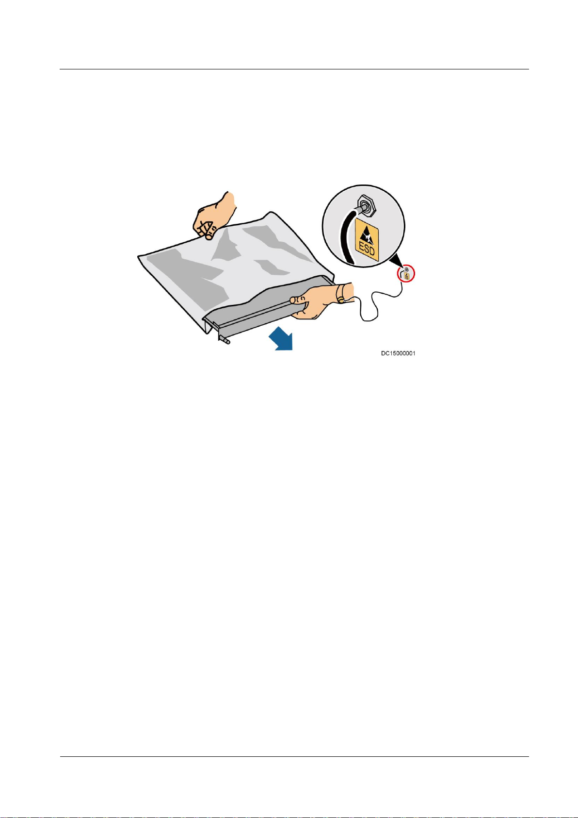
Wear ESD gloves or a well-grounded ESD wrist strap when touching the device or
handling boards or application-specific integrated circuits (ASICs).
When holding a board, hold its edge without touching any components. Do not touch the
components with your bare hands.
Package boards with ESD packaging materials before storing or transporting them.
Figure 1-1 Wearing an ESD wrist strap
Neutral-Ground Voltage
It is recommended that the three-phase loads be equalized and the neutral-ground voltage be
kept at less than 2 V to meet power distribution requirements.
1.4 Installation Environment Requirements
To prevent fire due to high temperature, ensure that the ventilation vents or heat
dissipation system are not blocked when the equipment is running.
Install the equipment in an area far away from liquids. Do not install it under areas prone
to condensation, such as under water pipes and air exhaust vents, or areas prone to water
leakage, such as air conditioner vents, ventilation vents, or feeder windows of the
equipment room. Ensure that no liquid enters the equipment to prevent faults or short
circuits.
If any liquid is detected inside the equipment, immediately disconnect the power supply
and contact the administrator.
Do not expose the equipment to flammable or explosive gas or smoke. Do not perform
any operation on the equipment in such environments.
Ensure that the equipment room provides good heat insulation, and the walls and floor
are dampproof.
Install a rat guard at the door of the equipment room.
Page 15

UPS5000-E-(360 kVA-480 kVA)
User Manual (40 kVA Power Modules)
1 Safety Information
Issue 07 (2020-01-10)
Copyright © Huawei Technologies Co., Ltd.
7
Installation at Heights
Working at heights refers to operations that are performed at least 2 meters above the
ground.
Do not work at heights if the steel pipes are wet or other potential danger exists. After the
preceding conditions no longer exist, the safety director and relevant technical personnel
need to check the involved equipment. Operators can begin working only after obtaining
consent.
When working at heights, comply with local relevant laws and regulations.
Only trained and qualified personnel are allowed to work at heights.
Before working at heights, check the climbing tools and safety gears such as safety
helmets, safety belts, ladders, springboards, scaffolding, and lifting equipment. If they do
not meet the requirements, take corrective measures or disallow working at heights.
Wear personal protective equipment such as the safety helmet and safety belt or waist
rope and fasten it to a solid structure. Do not mount it on an insecure moveable object or
metal object with sharp edges. Make sure that the hooks will not slide off.
Set a restricted area and eye-catching signs for working at heights to warn away
irrelevant personnel.
Carry the operation machinery and tools properly to prevent them from falling off and
causing injuries.
Personnel involving working at heights are not allowed to throw objects from the height
to the ground, or vice versa. Objects should be transported by tough slings, hanging
baskets, highline trolleys, or cranes.
Ensure that guard rails and warning signs are set at the edges and openings of the area
involving working at heights to prevent falls.
Do not pile up scaffolding, springboards, or other sundries on the ground under the area
involving working at heights. Do not allow people to stay or pass under the area
involving working at heights.
Inspect the scaffolding, springboards, and workbenches used for working at heights in
advance to ensure that their structures are solid and not overloaded.
Any violations must be promptly pointed out by the site manager or safety supervisor
and the involved personnel should be prompted for correction. Personnel who fail to stop
violations will be forbidden from working.
1.5 Mechanical Safety
Hoisting Devices
Do not walk under hoisted objects.
Only trained and qualified personnel should perform hoisting operations.
Check that hoisting tools are available and in good condition.
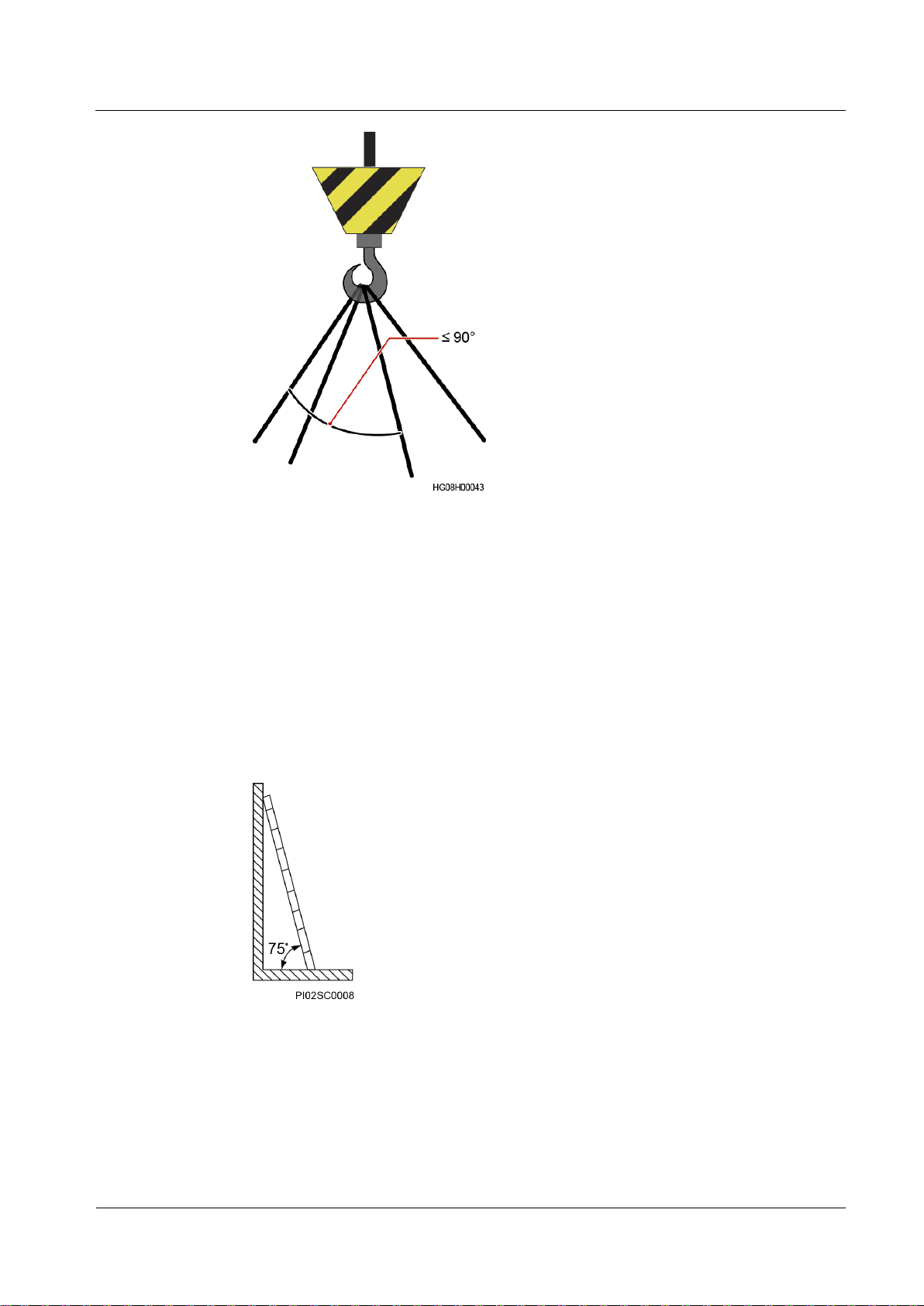
Before hoisting objects, ensure that hoisting tools are firmly secured onto a load-bearing
object or wall.
Ensure that the angle formed by two hoisting cables is no more than 90 degrees, as
shown in the following figure.
Page 16
UPS5000-E-(360 kVA-480 kVA)
User Manual (40 kVA Power Modules)
1 Safety Information
Issue 07 (2020-01-10)
Copyright © Huawei Technologies Co., Ltd.
8
Do not drag steel ropes and hoisting tools or bump hoisted objects against hard objects
during hoisting.
Using Ladders
Use wooden or fiberglass ladders when you need to perform live working at heights.
When a step ladder is used, ensure that the pull ropes are secured and the ladder is held
firm.
Before using a ladder, check that it is intact and confirm its load bearing capacity. Do not
overload it.
Ensure that the ladder is securely positioned. The recommended angle for a ladder
against the floor is 75 degrees, as shown in the following figure. An angle rule can be
used to measure the angle. Ensure that the wider end of the ladder is at the bottom, or
protective measures have been taken at the bottom to prevent the ladder from sliding.
When climbing a ladder, take the following precautions to reduce risks and ensure
safety:
Keep your body steady.
Do not climb higher than the fourth rung of the ladder from the top.
Ensure that your body's center of gravity does not shift outside the legs of the ladder.
Page 17
UPS5000-E-(360 kVA-480 kVA)
User Manual (40 kVA Power Modules)
1 Safety Information
Issue 07 (2020-01-10)
Copyright © Huawei Technologies Co., Ltd.
9
Drilling Holes
When drilling holes into a wall or floor, observe the following safety precautions:
Do not drill holes into the equipment. Doing so may affect the electromagnetic shielding of
the equipment and damage components or cables inside. Metal shavings from drilling may
short-circuit boards inside the equipment.
Obtain the consent from the customer, subcontractor, and Huawei before drilling.
Wear goggles and protective gloves when drilling holes.
When drilling holes, protect the equipment from shavings. After drilling, clean up any
shavings that have accumulated inside or outside the equipment.
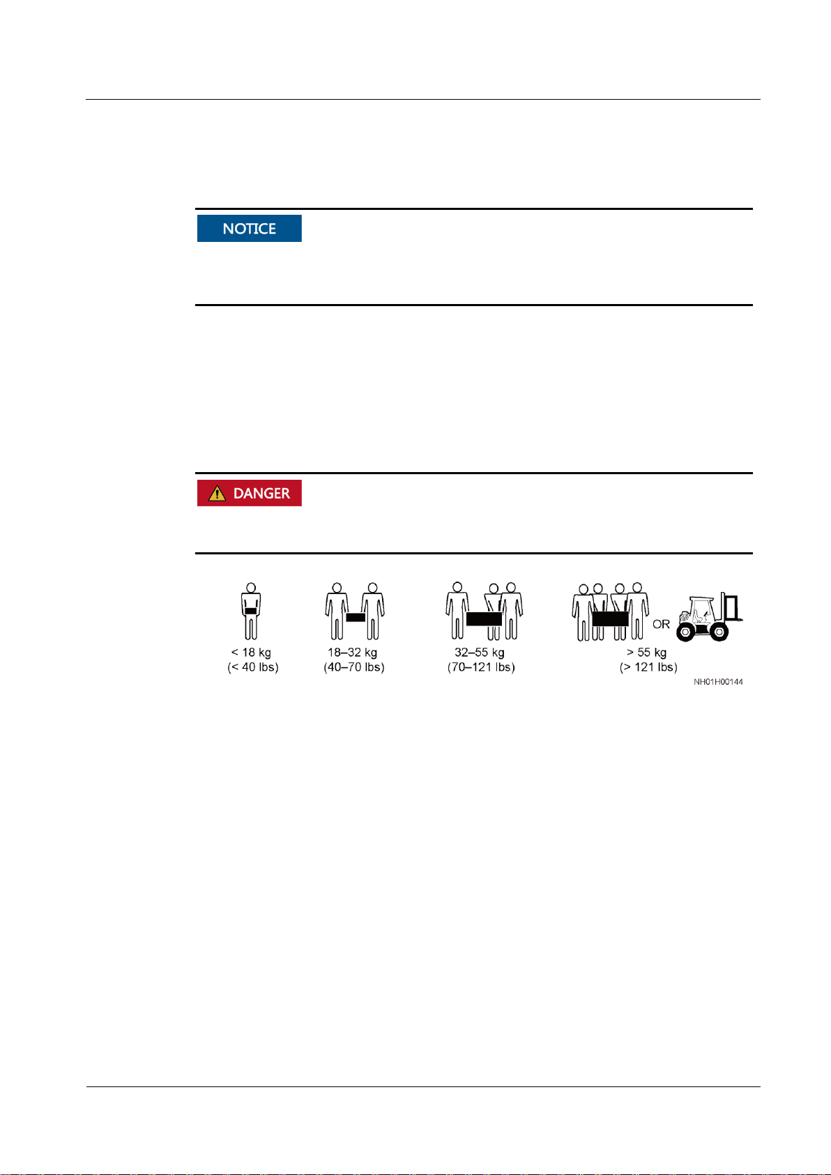
Moving Heavy Objects
When removing a heavy or unstable component from a cabinet, be aware of unstable or heavy
objects on the cabinet.
Be cautious to avoid injury when moving heavy objects.
When moving the equipment by hand, wear protective gloves to prevent injuries.
Move or lift the equipment by holding its handles or lower edges. Do not hold the
handles of modules (such as power supply units, fans, and boards) that are installed in
the equipment because they cannot support the weight of the equipment.
Avoid scratching the cabinet surface or damaging cabinet components and cables during
equipment transportation.
When transporting the equipment using a forklift truck, ensure that the forks are properly
positioned to ensure that the equipment does not topple. Before moving the equipment,
secure it to the forklift truck using ropes. When moving the equipment, assign dedicated
personnel to take care of it.
Choose railways, sea, or a road with good condition for transportation to ensure
equipment safety. Avoid tilt or jolt during transportation.
Move a cabinet with caution. Any bumping or falling may damage the equipment.
Page 18
UPS5000-E-(360 kVA-480 kVA)
User Manual (40 kVA Power Modules)
1 Safety Information
Issue 07 (2020-01-10)
Copyright © Huawei Technologies Co., Ltd.
10
1.6 Device Running Safety
The UPS is used for commercial and industrial purposes only. It cannot be used as a power
supply for life support devices.
For power supply systems that are critical to significant economic interests or public order,
such as the national computing center, military command system, emergency command
center, railway signal system and control center, civil aviation and air traffic control center,
airport command center, financial clearing center, and transaction center, the Tier 4 or 3 power
architecture specified in TIA-942 must be used. That is, two power supplies must be used to
supply power to loads.
Ensure that the equipment is used in an environment that meets the product design
specifications (including power grid, temperature, and humidity). Otherwise, the equipment
may become faulty, and the resulting equipment malfunction and component damage are not
covered under the warranty.
The UPS operating environment must meet the requirements for the climate indicator,
mechanically active substance indicator, and chemically active substance indicator in ETSI
EN 300 019-1 class 3.6.
After unpacking the UPS, you are advised to power on the UPS as soon as possible. If you
temporarily do not use the UPS, take appropriate measures to prevent moisture, dust, and
foreign matter from entering the UPS.
After unpacking batteries, you are advised to connect the battery supply as soon as
possible. If you temporarily do not use the batteries, store them in a dry and clean
environment. If batteries are stored for more than 90 days, charge them in time. Otherwise,
the battery lifespan may be affected.
Install the UPS in an area far away from liquids. Do not install it under areas prone to
water leakage, such as air conditioner vents, ventilation vents, or feeder windows of the
equipment room. Ensure that no liquid enters the UPS to prevent short circuits. Ensure that
there is no condensation inside the equipment or equipment room.
If any liquid is detected inside the equipment, immediately disconnect the power supply
and contact the administrator.
Do not expose the equipment to flammable or explosive gas or smoke. Do not perform any
operation on the equipment in such environments.
During installation and maintenance, ensure that sundries do not enter the UPS. Otherwise,
equipment damage, load power derating, power failure, and personal injury may occur.
If the valid mains voltage exceeds 320 V AC, the UPS may be damaged.
A UPS can be used to serve resistive-capacitive loads, resistive loads, and micro-inductive
loads. It is recommended that a UPS not be used for pure capacitive loads, pure inductive
loads, and half-wave rectification loads. A UPS does not apply to regeneration loads.
Page 19

UPS5000-E-(360 kVA-480 kVA)
User Manual (40 kVA Power Modules)
1 Safety Information
Issue 07 (2020-01-10)
Copyright © Huawei Technologies Co., Ltd.
11
Any operation on any electrical device in an environment that has inflammable air can cause
extreme danger. Strictly obey the operating environmental requirements specified in related
user manuals when using or storing the device.
The UPS can be configured with a backfeed protection dry contact to work with an external
automatic circuit breaker, preventing the voltage from flowing back to input terminals over
static bypass circuits. If the installation and maintenance personnel do not need backfeed
protection, paste labels on external mains and bypass input switches, informing that the UPS
is connected to a backfeed protection card. Disconnect the backfeed protection card from the
UPS before operating the UPS.
Do not use the UPS in the following places:
Environments that are close to flammable or explosive materials, dust, corrosive gases or
dust, conductive or magnetic dust, abnormal vibration, or collision
Rooms or outdoor environments where temperature and humidity are not controlled
(with high temperature, low temperature, moisture, direct sunlight, or heat sources)
Non-confined environments near the ocean (0–3.7 km) and indoor or semi-indoor
environments where the temperature and humidity are not controllable, such as simple
equipment rooms, civil houses, garages, corridors, and direct ventilation cabinets near
the sea; or houses with only roofs, railway station platforms, gymnasiums, and
aquariums
Environments that are conducive for the growth of microorganisms such as fungus or
mildew
Environments where rodents (such as mice) and insects exist
1.7 Battery Safety
Basic Requirements
Before operating batteries, carefully read the safety precautions for battery handling and
master the correct battery connection methods.
Do not expose batteries at high temperatures or around heat-generating devices, such as
sunlight, fire sources, transformers, and heaters. Excessive heat exposure may cause the
batteries to explode.
Do not burn batteries. Otherwise, the batteries may explode.
To avoid leakage, overheating, fire, or explosions, do not disassemble, alter, or damage
batteries, for example, insert sundries into batteries or immerse batteries in water or other
liquids.
Wear goggles, rubber gloves, and protective clothing to prevent skin contact with
electrolyte in the case of electrolyte overflow. If a battery leaks, protect the skin or eyes
from the leaking liquid. If the skin or eyes come in contact with the leaking liquid, wash
it immediately with clean water and go to the hospital for medical treatment.
Use dedicated insulated tools.
Move batteries in the required direction. Do not place a battery upside down or tilt it.
Page 20

UPS5000-E-(360 kVA-480 kVA)
User Manual (40 kVA Power Modules)
1 Safety Information
Issue 07 (2020-01-10)
Copyright © Huawei Technologies Co., Ltd.
12
Keep the battery loop disconnected during installation and maintenance.
Use batteries of specified models. Using batteries of other models may damage the
batteries.
Dispose of waste batteries in accordance with local laws and regulations. Do not dispose
of batteries as household waste. If a battery is disposed of improperly, it may explode.
The site must be equipped with qualified fire extinguishing facilities, such as firefighting
sands and powder fire extinguishers.
To ensure battery safety and battery management accuracy, use batteries provided with the
UPS by Huawei. Huawei is not responsible for any battery faults caused by batteries not
provided by Huawei.
Battery Installation
Before installing batteries, observe the following safety precautions:
Install batteries in a well-ventilated, dry, and cool environment that is far away from heat
sources, flammable materials, moistures, extensive infrared radiation, organic solvents,
and corrosive gases. Take fire prevention measures.
Place and secure batteries horizontally.
Note the polarities when installing batteries. Do not short-circuit the positive and
negative poles of the same battery or battery string. Otherwise, the battery may be shortcircuited.
Check battery connections periodically, ensuring that all bolts are securely tightened.
When installing batteries, do not place installation tools on the batteries.
Battery Short Circuit
Battery short circuits can generate high instantaneous current and release a great amount of
energy, which may cause equipment damage or personal injury.
To avoid battery short-circuit, do not maintain batteries with power on.
Flammable Gas
Page 21
UPS5000-E-(360 kVA-480 kVA)
User Manual (40 kVA Power Modules)
1 Safety Information
Issue 07 (2020-01-10)
Copyright © Huawei Technologies Co., Ltd.
13
Lead-acid batteries emit flammable gas when used. Ensure that batteries are kept in a wellventilated area and take preventive measures against fire.
Battery Leakage
Battery overheating causes deformation, damage, and electrolyte spillage.
When the electrolyte overflows, absorb and neutralize the electrolyte immediately. When
moving or handling a battery whose electrolyte leaks, note that the leaking electrolyte may
hurt human bodies.
Do not use unsealed lead-acid batteries.
To prevent fire or corrosion, ensure that flammable gas (such as hydrogen) is properly
exhausted for lead-acid batteries.
Lithium Battery
The safety precautions for lithium batteries are similar to those for lead-acid batteries except
that you also need to note the precautions described in this section.
There is a risk of explosion if a battery is replaced with an incorrect model.
If the battery temperature exceeds 60°C, check for and promptly handle any leakage.
Electrolyte overflow may damage the equipment. It will corrode metal parts and boards,
and ultimately damage the boards.
If the electrolyte overflows, follow the instructions of the battery manufacturer or
neutralize the electrolyte by using sodium bicarbonate (NaHCO3) or sodium carbonate
(Na2CO3).
A battery can be replaced only with a battery of the same or similar model recommended
by the manufacturer.
When handling a lithium battery, do not place it upside down, tilt it, or bump it with
other objects.
Keep the lithium battery loop disconnected during installation and maintenance.
Do not charge a battery when the ambient temperature is below the lower limit of the
operating temperature (charging is forbidden at 0°C). Low-temperature charging may
cause crystallization, which will result in a short circuit inside the battery.
Page 22

UPS5000-E-(360 kVA-480 kVA)
User Manual (40 kVA Power Modules)
1 Safety Information
Issue 07 (2020-01-10)
Copyright © Huawei Technologies Co., Ltd.
14
1.8 Others
Use batteries within the allowed temperature range; otherwise, the battery performance
and safety will be compromised.
Do not throw a lithium battery in fire.
When maintenance is complete, return the waste lithium battery to the maintenance
office.
Exercise caution when manually shutting down the UPS inverter for transferring to
bypass mode, or when adjusting the UPS output voltage level or frequency. Doing so
may affect the power supply to equipment.
Exercise caution when setting battery parameters. Incorrect settings will affect the power
supply and battery lifespan.
Page 23
UPS5000-E-(360 kVA-480 kVA)
User Manual (40 kVA Power Modules)
2 Overview
Issue 07 (2020-01-10)
Copyright © Huawei Technologies Co., Ltd.
15
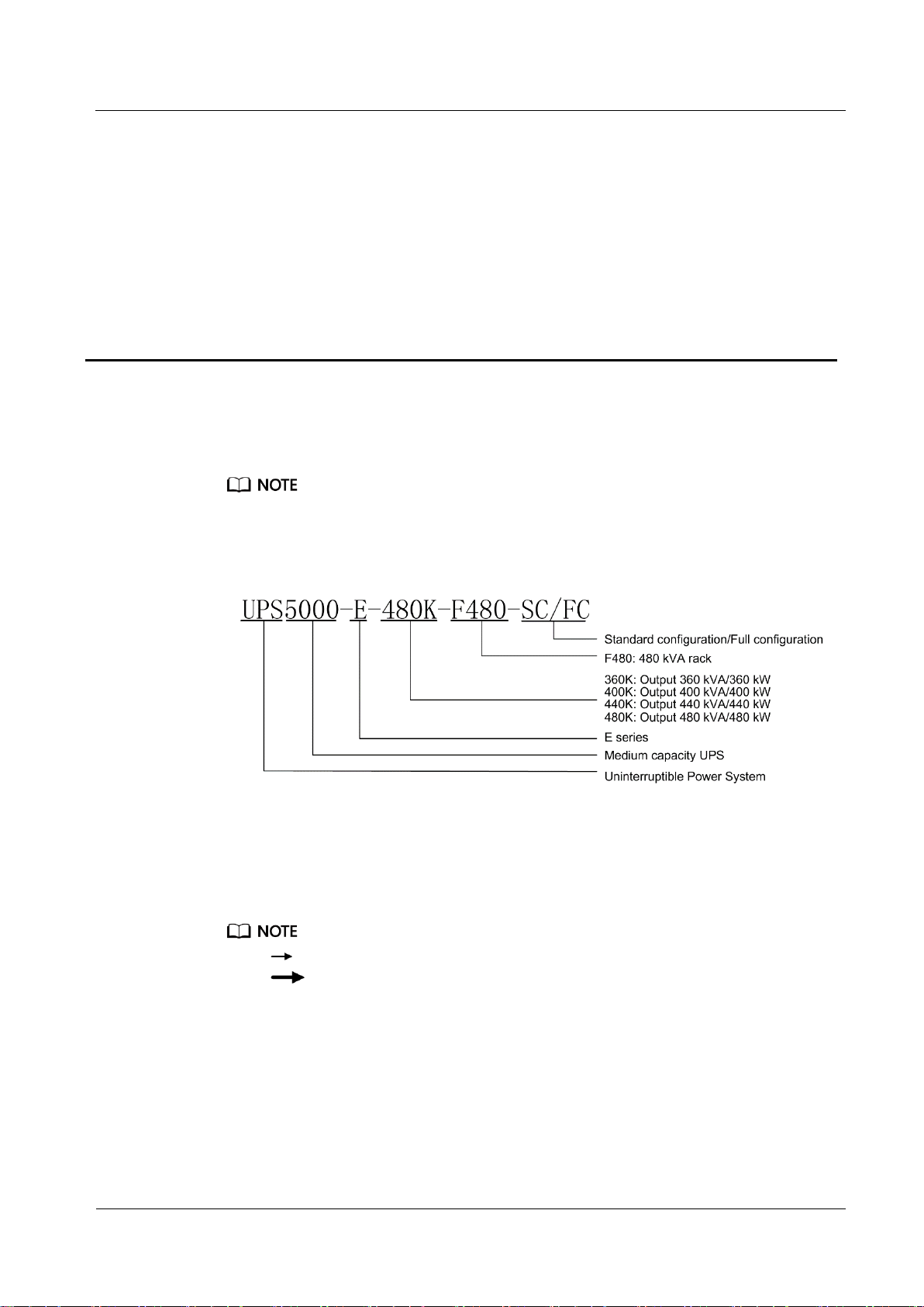
2.1 Model Description
The structural drawings and graphical user interface (GUI) appeared in this document are those of
UPS5000-E-480 kVA.
Figure 2-1 Model number
2 Overview
2.2 Working Principle
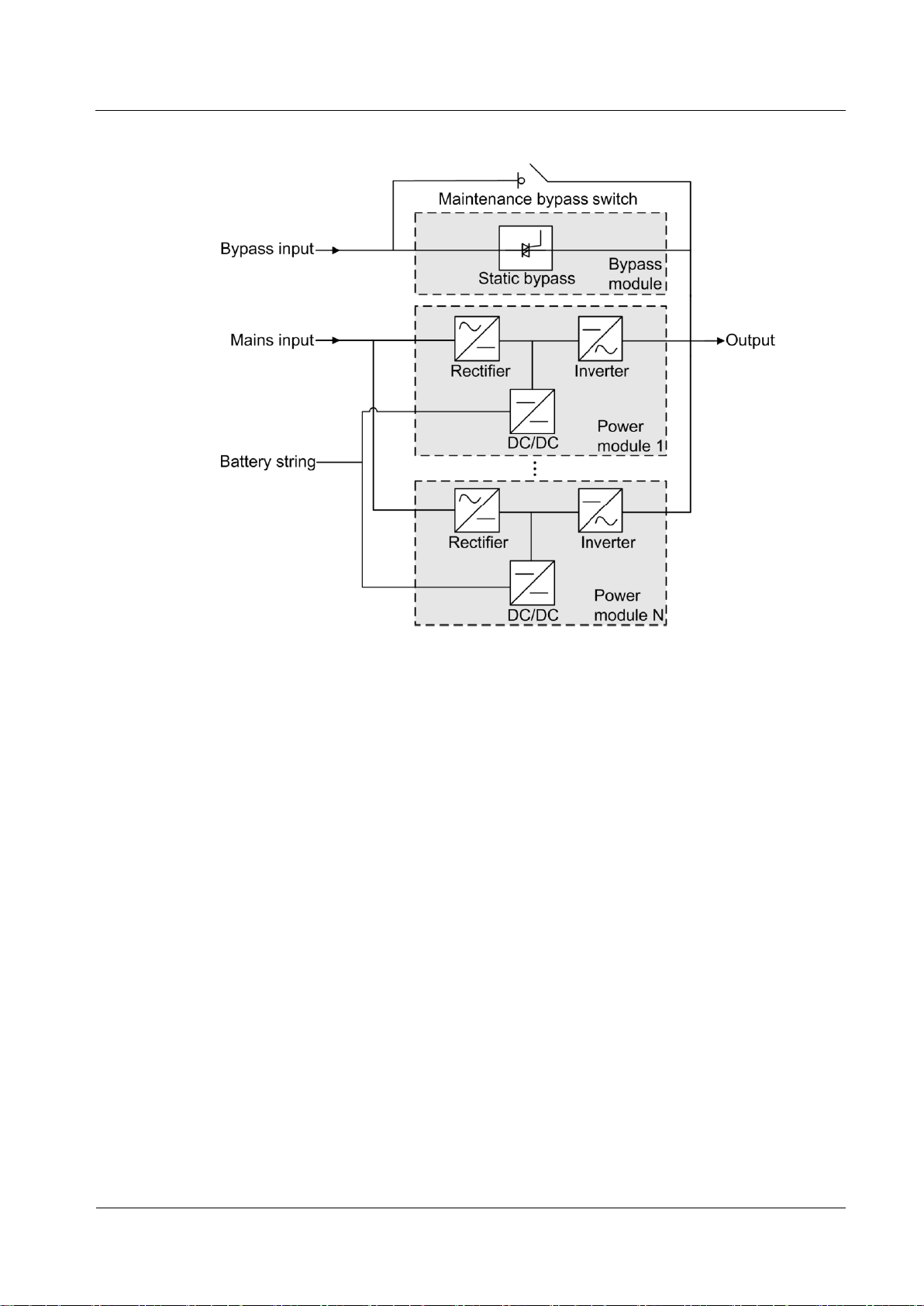
2.2.1 Conceptual Diagram
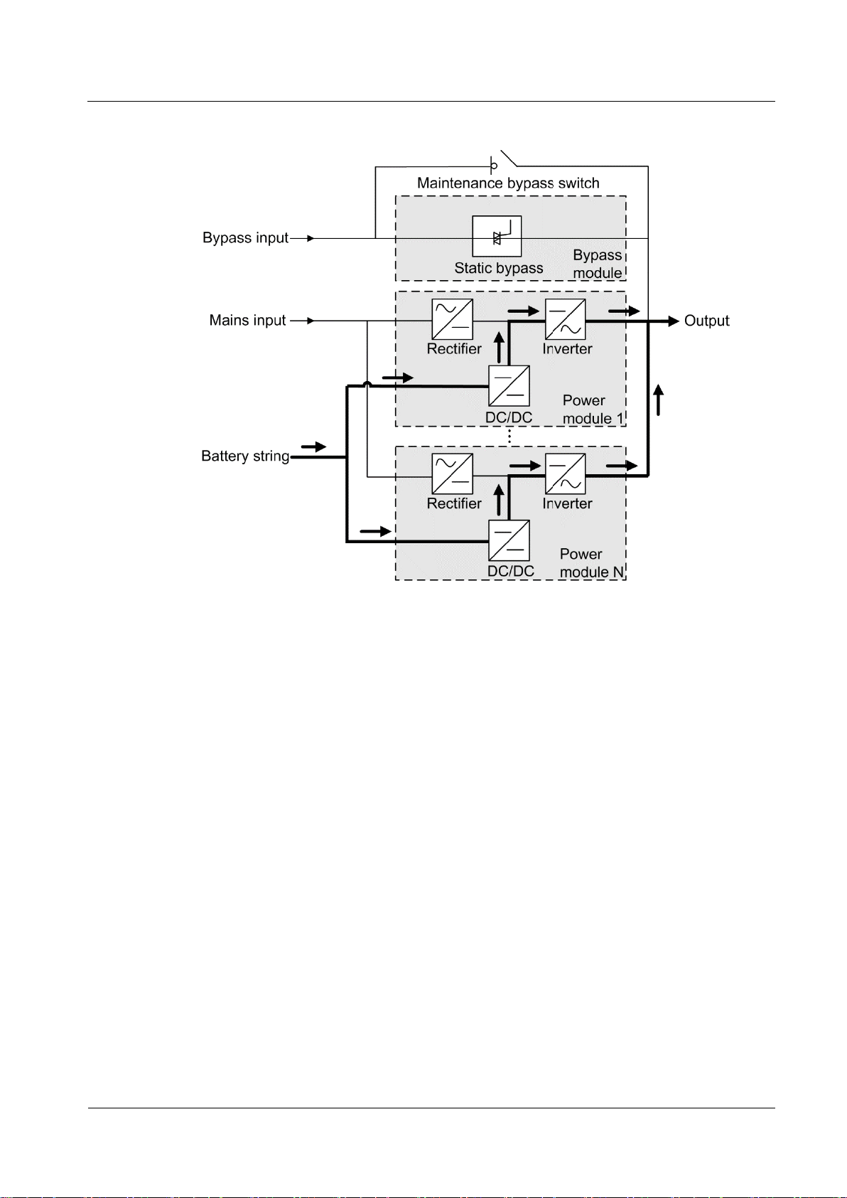
The UPS5000 is an online product. It uses a modular design, which facilitates maintenance
and capacity expansion. The UPS5000 adopts intelligent control. Its power module consists of
a rectifier, inverter, and DC/DC converter. The UPS5000 converts inputs into pure highquality sine wave outputs by using the high-frequency switching technology.
indicates an input mode.
indicates the energy flow direction.
Page 24
UPS5000-E-(360 kVA-480 kVA)
User Manual (40 kVA Power Modules)
2 Overview
Issue 07 (2020-01-10)
Copyright © Huawei Technologies Co., Ltd.
16
Figure 2-2 UPS conceptual diagram
2.2.2 Working Modes
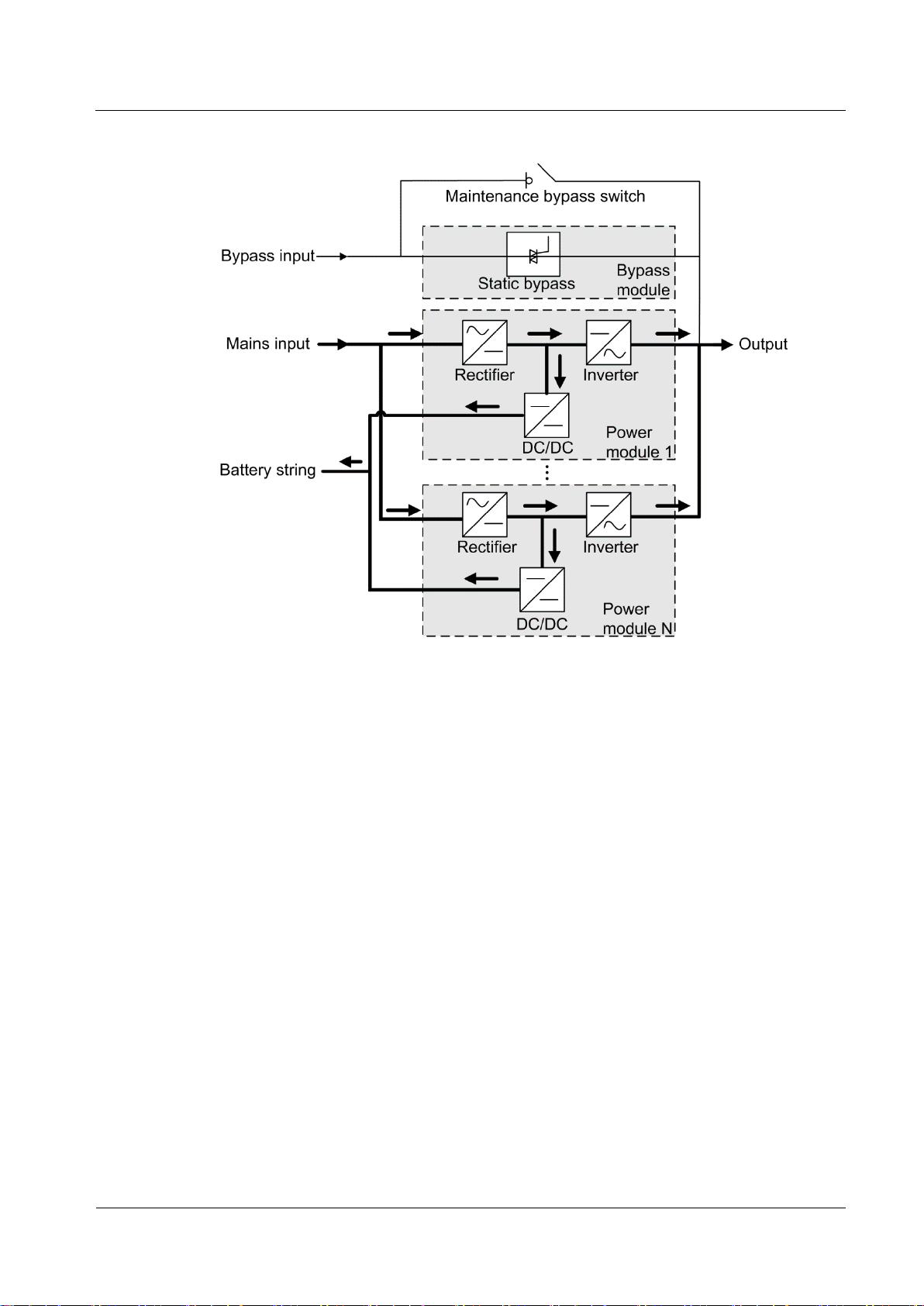
2.2.2.1 Normal Mode
In normal mode, the rectifier converts AC power into DC power, then the inverter converts
DC power into high-precision AC outputs. The conversions protect loads from interference
such as input harmonics, glitches, and voltage transients.
Page 25
UPS5000-E-(360 kVA-480 kVA)
User Manual (40 kVA Power Modules)
2 Overview
Issue 07 (2020-01-10)
Copyright © Huawei Technologies Co., Ltd.
17
Figure 2-3 UPS conceptual diagram in normal mode
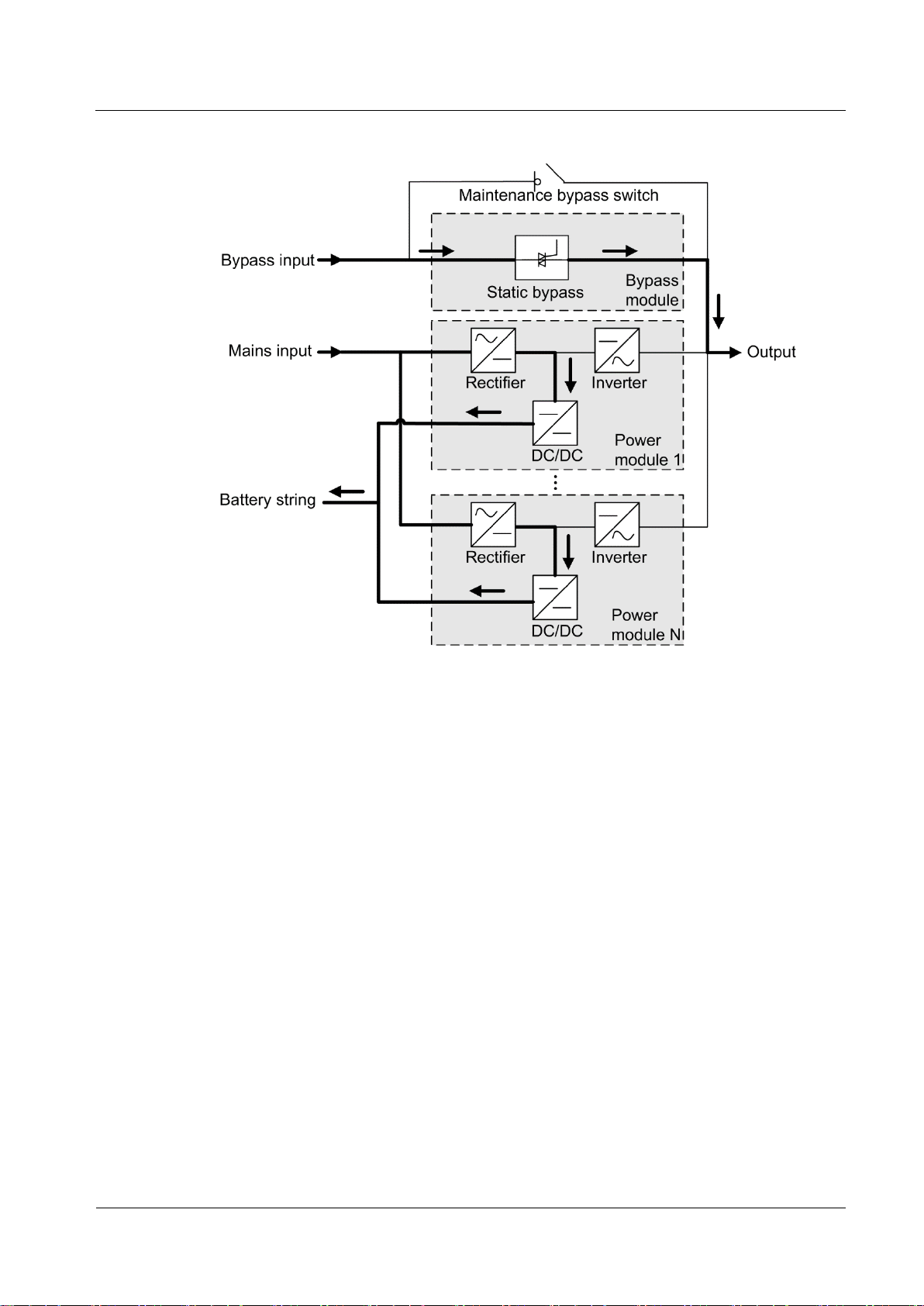
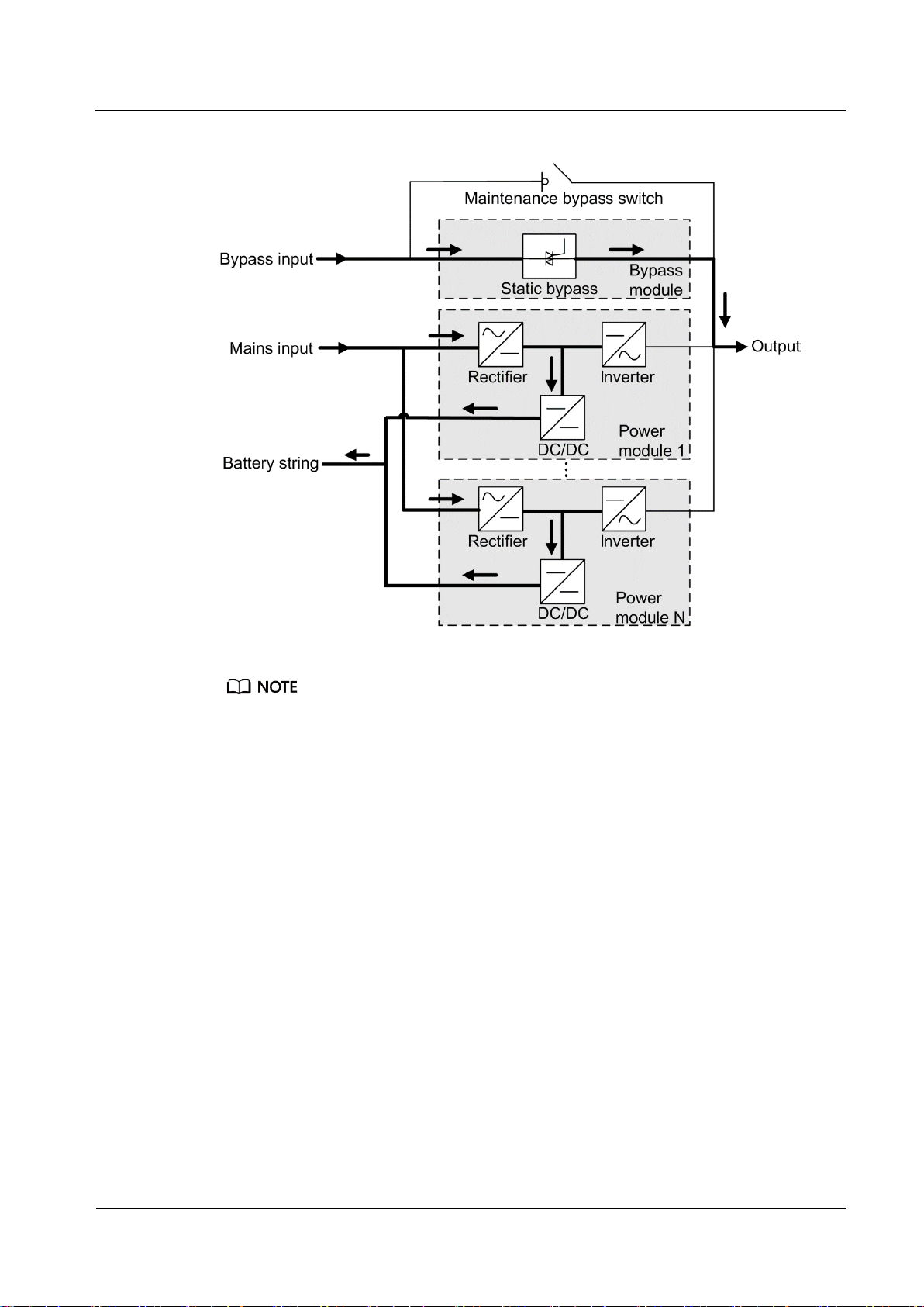
2.2.2.2 Bypass Mode
The UPS automatically transfers to bypass mode upon detecting power module
overtemperature, overload, or other faults that may cause the inverter to shut down. The
bypass power supply is not protected by the UPS which means it may be affected by mains
outage, and incorrect AC voltage or frequency.
Page 26
UPS5000-E-(360 kVA-480 kVA)
User Manual (40 kVA Power Modules)
2 Overview
Issue 07 (2020-01-10)
Copyright © Huawei Technologies Co., Ltd.
18
Figure 2-4 UPS conceptual diagram in bypass mode
2.2.2.3 Battery Mode
If the mains input is abnormal or the rectifier becomes abnormal, the UPS transfers to battery
mode. The power module obtains DC power from batteries, and the power is converted into
AC output by the inverter.
Page 27
UPS5000-E-(360 kVA-480 kVA)
User Manual (40 kVA Power Modules)
2 Overview
Issue 07 (2020-01-10)
Copyright © Huawei Technologies Co., Ltd.
19
Figure 2-5 UPS conceptual diagram in battery mode
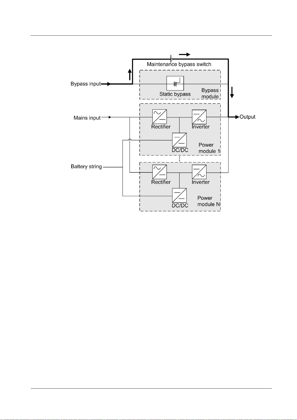
2.2.2.4 Maintenance Bypass Mode
When the UPS works in maintenance bypass mode, the current flows through the
maintenance bypass instead of the power module. You can maintain the circuit inside the
cabinet.
Page 28
UPS5000-E-(360 kVA-480 kVA)
User Manual (40 kVA Power Modules)
2 Overview
Issue 07 (2020-01-10)
Copyright © Huawei Technologies Co., Ltd.
20
Figure 2-6 UPS conceptual diagram in maintenance bypass mode
2.2.2.5 ECO Mode
The economic control operation (ECO) mode is an economical working mode, which can be
configured on the LCD or web user interface (WebUI). In ECO mode, when the bypass input
is within the ECO voltage and frequency ranges and other ECO power supply conditions are
met, the UPS works in bypass mode and the inverter is in standby state. When the bypass
voltage is outside the ECO voltage range, the UPS transfers from bypass mode to normal
mode. In bypass mode or normal mode, the rectifier keeps working and charges batteries
using a charger. The ECO mode delivers a high efficiency.
Page 29
UPS5000-E-(360 kVA-480 kVA)
User Manual (40 kVA Power Modules)
2 Overview
Issue 07 (2020-01-10)
Copyright © Huawei Technologies Co., Ltd.
21
Figure 2-7 UPS conceptual diagram in ECO mode
Manual startup is required to ensure that the inverter is in standby state and the power flow has reached
the inverter.
Page 30
UPS5000-E-(360 kVA-480 kVA)
User Manual (40 kVA Power Modules)
2 Overview
Issue 07 (2020-01-10)
Copyright © Huawei Technologies Co., Ltd.
22
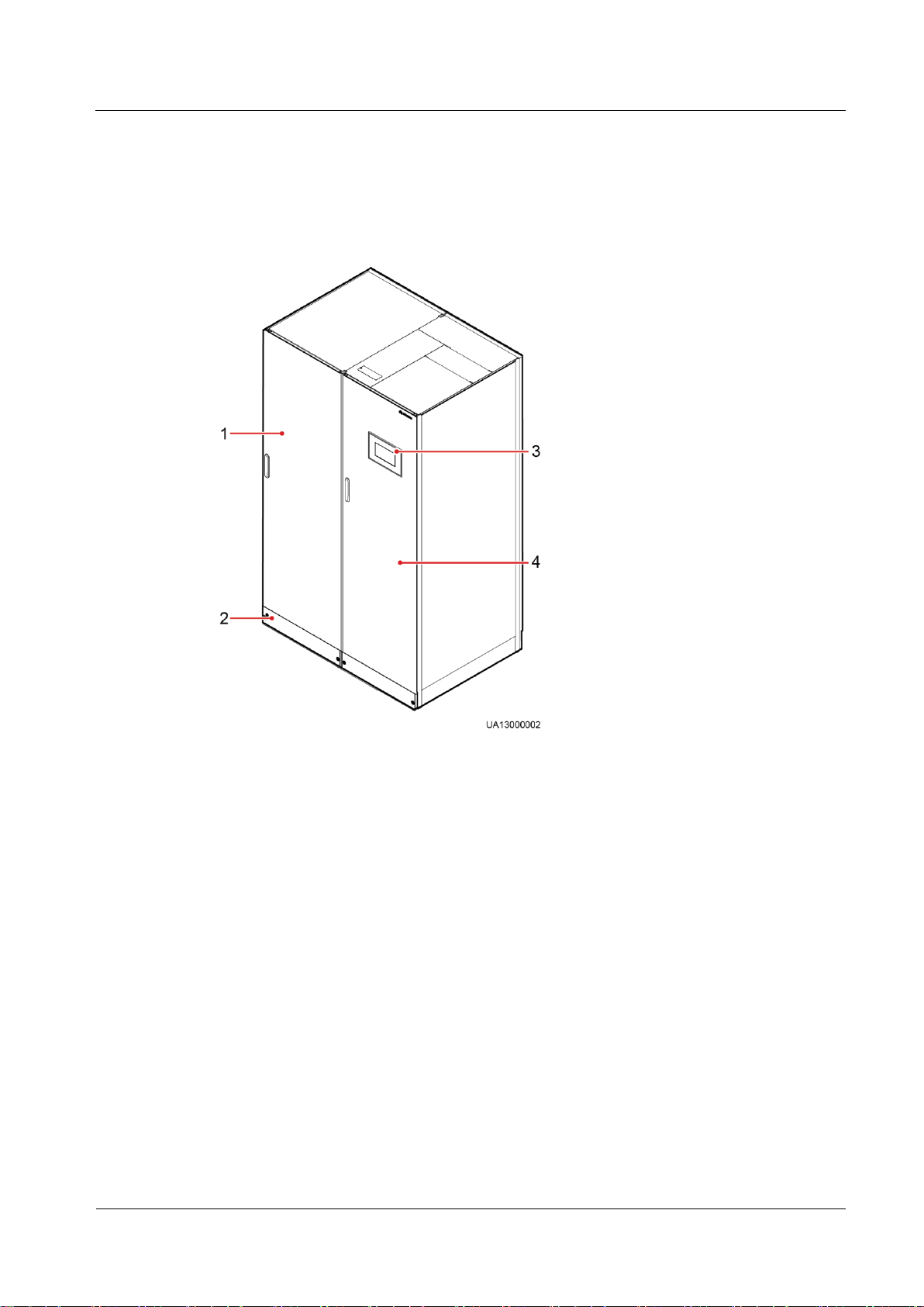
2.3 Product Description
(1) Power
cabinet
(2) Anchor baffle
plates
(3) Monitor display unit
(MDU)
(4) Bypass
cabinet
2.3.1 Appearance
Figure 2-8 UPS
Page 31

UPS5000-E-(360 kVA-480 kVA)
User Manual (40 kVA Power Modules)
2 Overview
Issue 07 (2020-01-10)
Copyright © Huawei Technologies Co., Ltd.
23
2.3.2 Product Structure
(1) Power modules
(2) Control module
(3) Optional card slot
(behind the filler panel)
(4) Power distribution unit (PDU)
covers (four pieces)
(5) Maintenance
bypass switch
(6) Bypass module
Figure 2-9 Product structure (UPS with standard line configurations)
Page 32

UPS5000-E-(360 kVA-480 kVA)
User Manual (40 kVA Power Modules)
2 Overview
Issue 07 (2020-01-10)
Copyright © Huawei Technologies Co., Ltd.
24
Figure 2-10 Product structure (UPS with full copper bar configurations)
(1) Power modules
(2) Control module
(3) Optional card slot (behind the filler
panel)
(4) Mains input switch
(5) Output switch
(6) Power distribution unit covers (four
pieces)
(7) Maintenance bypass
switch
(8) Bypass input
switch
(9) Bypass module
A UPS in standard configurations has only one switch, that is, the maintenance bypass switch. A UPS in
full configurations has four switches. They are the mains input switch, mains output switch, maintenance
bypass switch, and bypass input switch from the top to the bottom.
2.4 Control Module
2.4.1 Overview
In a standard configuration, the control module consists of two ECMs, one dry contact card,
and one monitoring interface card (from left to right). The four cards are hot swappable. One
Page 33

UPS5000-E-(360 kVA-480 kVA)
User Manual (40 kVA Power Modules)
2 Overview
Issue 07 (2020-01-10)
Copyright © Huawei Technologies Co., Ltd.
25
subrack is reserved above the dry contact card. A backfeed protection card or dry contact
(1) Ground terminal
(2) Parallel port 1
(3) BSC port
1
(4) Ready switch
on ECM 1
(5) Indicators for ECM 1
(6) Parallel port 2
(7) BSC port
2
(8) Ready switch
on ECM 2
(9) Indicators for ECM 2
(10) Dry contact card
(11) Dry
contacts
(12) MDU port
(13) RS485 port
(14) Fast Ethernet (FE)
port
(15) COM2
port
(16) COM1 port
(17) Battery temperature
sensor port
(18) Optional card
subrack cover
extended card can be inserted into this subrack.
Figure 2-11 Signal panel on the control module
2.4.2 ECM
Appearance
Ports are protected by a security mechanism.
The control module consists of two energy control modules (ECMs) in active/standby mode.
Figure 2-12 ECM
Page 34

UPS5000-E-(360 kVA-480 kVA)
User Manual (40 kVA Power Modules)
2 Overview
Issue 07 (2020-01-10)
Copyright © Huawei Technologies Co., Ltd.
26
Table 2-1 Ports on the ECM
Silk Screen
Description
PARALLEL
The PARALLEL port transmits parallel signals between racks.
BSC
The BSC port is used in a dual-bus system to synchronize output
frequencies and phases between UPS systems, ensuring that two buses
can switch with each other.
BSC cables are hot-swappable.
Indicator
Color
Status
Description
NORMAL
Green
Steady on
This ECM is the active ECM.
Blinking at
0.5 Hz
This ECM is the standby ECM and it is ready.
Off
This ECM is not ready or the CPLD of this
ECM is being upgraded.
Blinking at
4 Hz
The DSP of the ECM is being upgraded or not
configured.
ALM
Yellow
Steady on
The ECM has a minor alarm, but it does not
need to be replaced.
Off
The ECM has no minor alarm or the DSP of the
ECM is being upgraded.
FAULT
Red
Steady on
The ECM has a critical alarm.
Off
The ECM has no critical alarm or the DSP of the
ECM is being upgraded.
For a single UPS, the parallel cable is not needed.
Table 2-2 Indicator description
Functions
As a control interface for the entire system, the ECM communicates with each module
and provides a bus to communicate with the dry contact card. The ECM ensures
equalized output currents between modules so that load power is equally shared.
Provides module running information for the MDU.
Controls the running of a single UPS5000 and a parallel system, and reports the
UPS5000 status information to other monitoring modules.
The system provides three types of CAN communication: monitoring CAN
communication, intra-rack parallel CAN communication, and inter-rack parallel CAN
communication.
Page 35

UPS5000-E-(360 kVA-480 kVA)
User Manual (40 kVA Power Modules)
2 Overview
Issue 07 (2020-01-10)
Copyright © Huawei Technologies Co., Ltd.
27
Specifications
Silk Screen
Description
Status
Initial Status
BTG
Port for detecting battery
grounding faults
Connected: battery
grounding fault
Disconnected: no
battery grounding
fault
Disconnected
0V
Port for signal ground
GEN
Port for detecting diesel
generator (D.G.) mode
Connected: D.G.
mode
Disconnected:
non-D.G. mode
Disconnected
0V
Port for signal ground
Figure 2-13 Logical connections for CAN communication
Hot-swappable
1 U high
2.4.3 Dry contact card
Appearance
Figure 2-14 Dry contact card
Table 2-3 Ports on the dry contact card
Page 36

UPS5000-E-(360 kVA-480 kVA)
User Manual (40 kVA Power Modules)
2 Overview
Issue 07 (2020-01-10)
Copyright © Huawei Technologies Co., Ltd.
28
Silk Screen
Description
Status
Initial Status
BCB_OL
Port for detecting the BCB
box
Grounded: BCB
box connected
Disconnected:
BCB box not
connected
Grounded
BCB_STA
Port for monitoring the
battery switch
Connected: battery
switch ON
Disconnected:
battery switch
OFF
Disconnected
BCB_DRV
Controls battery circuit
breaker trip. When the
voltage is +12 V, the circuit
breaker trips.
0 V: battery switch
not tripped
12 V: battery
switch tripped
0 V
BCB_0V
Port for signal ground
EPO_NO
Emergency power-off (EPO)
port
If the normally open
(NO) port is
connected to the
EPO_12V port, EPO
is triggered.
Disconnected
EPO_12V
+12 V
EPO_NC
EPO port
If the normally closed
(NC) port is
disconnected from the
EPO_12V port, EPO
is triggered.
Connected
EPO_12V
+12 V
SWITCH
STATUS_OUT
Port for monitoring the UPS
output circuit breaker
Connected: circuit
breaker ON
Disconnected:
circuit breaker
OFF
Connected
SWITCH
STATUS_0V
Port for signal ground
SWITCH
STATUS_MT
Port for monitoring the
maintenance circuit breaker
Disconnected:
circuit breaker ON
Connected: circuit
breaker OFF
Disconnected
SWITCH
STATUS_0V
Port for signal ground
SWITCH
STATUS_BP
Port for monitoring the
bypass input circuit breaker
Connected: circuit
breaker ON
Disconnected:
circuit breaker
OFF
Connected
SWITCH
STATUS_0V
Port for signal ground
SPD
Port for monitoring the input
AC surge protective device
(SPD)
Connected: SPD
enabled
Disconnected:
SPD disabled
Connected
0V
Port for signal ground
Page 37

UPS5000-E-(360 kVA-480 kVA)
User Manual (40 kVA Power Modules)
2 Overview
Issue 07 (2020-01-10)
Copyright © Huawei Technologies Co., Ltd.
29
The dry contact interface card takes effect only after it is set on the monitoring system. Set the
unused dry contact signal to the unused status.
Set the EPO port to NO or NC as required.
When multiple UPSs are paralleled, all dry contact signals to be used need to connect to each UPS.
Single cables require dual-insulated twisted cables. If the length of a power cable is within 25–50 m,
its cross-sectional area must be 0.5 mm2 to 1.5 mm2.
Functions
The dry contact card allows the UPS to detect and manage the switch status of the battery
system (including the external battery switch) and implement remote emergency power-off
(EPO).
Specifications
Hot-swappable
0.5 U high
2.4.4 (Optional) Backfeed Protection Card
Backfeed can cause damage to the UPS, loads, and maintenance personnel. If backfeed
occurs, the backfeed protection card triggers alarm signals, or disconnects the backfeed loop.
The backfeed protection card uses relay contact signals. The signal ports support any power
signals with a voltage of no more than 240 V AC and a current of less than 4 A. For details,
see the UPS5000 Backfeed Protection Card User Manual (03021KQQ).
2.4.5 (Optional) Dry Contact Extended Card
The dry contact extended card provides five signal output ports and five signal input ports.
For details, see the UPS5000 Dry Contact Extended Card User Manual (03021RKN).
2.4.6 Monitoring Interface Card
The FE port resembles the RS485 port. Follow the silk screen when connecting
communications cables as, if the RS485 port is mistaken for the FE port during cable
connection, the WebUI cannot be connected and MDU communication fails. Conversely, if
the FE port is mistaken for the RS485 port during cable connection, RS485
communication fails.
Only once being set will dry contact signals take effect. Set unused dry contact signals to
the unused state on the LCD.
In a parallel system, ensure that used dry contacts properly connect to each UPS.
The monitoring interface card provides external ports as well as monitoring and control
functions for the MDU. The ports include the ambient temperature and humidity sensor port,
battery monitoring unit (BMU) port, FE port, battery temperature monitoring port, and
network management port. MDU functions include monitoring of the UPS, allowing users to
Page 38

UPS5000-E-(360 kVA-480 kVA)
User Manual (40 kVA Power Modules)
2 Overview
Issue 07 (2020-01-10)
Copyright © Huawei Technologies Co., Ltd.
30
set parameters, command delivery, information reports, and UPS key information and
Port
Silk
Screen
Description
DO_1
NO
DO_1 is used to output alarms and indicates critical
alarms by default. It can be set to indicate minor alarms,
bypass mode, battery mode, or low battery voltage.
COM
DO_2
NO
DO_2 is used to output alarms and indicates minor
alarms by default. It can be set to indicate critical
alarms, bypass mode, battery mode, or low battery
voltage.
COM
DO_3
NO
DO_3 is used to output alarms and indicates bypass
mode by default. It can be set to indicate critical alarms,
minor alarms, battery mode, or low battery voltage.
COM
DO_4
NO
DO_4 is used to output alarms and indicates battery
mode by default. It can be set to indicate critical alarms,
minor alarms, bypass mode, or low battery voltage.
When the UPS works in intelligent power mode, DO_4
indicates D.G. control, which cannot be changed.
COM
DB26
MDU
Provides FE, RS485, I2C, and CAN signals.
Battery
temperature
sensor port
B_TEMP
Connects to an indoor battery temperature sensor.
Southbound
COM1
Connects to an ambient temperature and humidity
parameters displayed on the LCD.
Figure 2-15 shows the signal ports on the monitoring interface card.
Figure 2-15 Monitoring interface card
Table 2-4 describes the ports on the monitoring interface card.
DO_1 to DO_4 meet the maximum voltage and current requirements of 30 V DC/1 A or 60 V DC/0.5 A.
Table 2-4 Ports on the monitoring interface card
Page 39

UPS5000-E-(360 kVA-480 kVA)
User Manual (40 kVA Power Modules)
2 Overview
Issue 07 (2020-01-10)
Copyright © Huawei Technologies Co., Ltd.
31
Port
Silk
Screen
Description
communications
port 1
sensor over two wires.
Southbound
communications
port 2
COM2
Connects to a southbound device, such as a BMU.
Network port
FE
Connects to the network port on a PC.
Northbound
communications
port
RS485
Connects to a northbound network management device
or a third-party network management device over two
wires.
Signal cables must be double-insulated twisted cables. If the cable length is 25–50 m, the crosssectional area must be 0.5–1.5 mm2.
RS485 cables and FE cables must be shielded cables.
Figure 2-16 and Figure 2-17 are recommended wiring methods for DO ports.
Figure 2-16 Wiring method 1
Figure 2-17 Wiring method 2
Figure 2-18 and Table 2-5 describe the COM1 pin definitions.
Page 40

UPS5000-E-(360 kVA-480 kVA)
User Manual (40 kVA Power Modules)
2 Overview
Issue 07 (2020-01-10)
Copyright © Huawei Technologies Co., Ltd.
32
Figure 2-18 COM1 pins
Pin
Description
1
GND
2
N/A
3
RS485-
4
RS485+
5
N/A
6
12V_PORT
Table 2-5 COM1 pin definition
Figure 2-19 and Table 2-6 describe the COM2 pin definitions.
Figure 2-19 COM2 pins
Page 41

UPS5000-E-(360 kVA-480 kVA)
User Manual (40 kVA Power Modules)
2 Overview
Issue 07 (2020-01-10)
Copyright © Huawei Technologies Co., Ltd.
33
Table 2-6 COM2 pin definition
Pin
Description
1
RS485+
2
RS485-
3
N/A
4
RS485+
5
RS485-
6
GND
7
CANH0
8
CANL0
Pin
Description
1
RS485_T+
2
RS485_T–
3
N/A
4
RS485_R+
5
RS485_R–
6
GND
Figure 2-20 and Table 2-7 describe the RS485 pin definitions.
Figure 2-20 RS485 pins
Table 2-7 RS485 pin definition
Page 42

UPS5000-E-(360 kVA-480 kVA)
User Manual (40 kVA Power Modules)
2 Overview
Issue 07 (2020-01-10)
Copyright © Huawei Technologies Co., Ltd.
34
Pin
Description
7
N/A
8
N/A
2.5 MDU
(1) Status indicator
(2) LCD touchscreen
Status
Color
Meaning
On
Red
A critical alarm has been generated, and the buzzer sounds
continuously.
Yellow
A minor alarm has been generated, and the buzzer buzzes at 2 Hz.
Green
The UPS is running properly or a warning has been generated.
Off
N/A
The MDU is powered off.
Appearance
If cables are prepared onsite, follow the three methods below:
Connect pin 1 and pin 2. Pin 1 connects to RS485+ and pin 2 connects to RS485–.
Connect pin 4 and pin 5. Pin 4 connects to RS485+ and pin 5 connects to RS485–.
Connect pins 1, 2, 4, and 5. Twist cables to pin 1 and pin 4 into one cable and then connect it to
RS485+. Twist cables to pin 2 and pin 5 into one cable and then connect it to RS485–.
Figure 2-21 MDU
Table 2-8 Status indicator
Page 43

UPS5000-E-(360 kVA-480 kVA)
User Manual (40 kVA Power Modules)
2 Overview
Issue 07 (2020-01-10)
Copyright © Huawei Technologies Co., Ltd.
35
No.
Port Name
Description
1
MUS05A
(DB26)
Connects to the MDU and monitoring interface card
2
FE
Network port
3
CAN
Reserved
4
RS485_1
Reserved
5
USB Host
After installing the WiFi module, locally connect to the
UPS over the Service Expert app. Obtain the initial
startup password during deployment. View or obtain
UPS running information during preventive
maintenance.
NOTE
Only Huawei service engineers or authorized service engineers are
allowed to use the WiFi module. To ensure security, remove the
WiFi module immediately after use.
Insert the USB flash drive, import and export the
configuration file, export run logs, and upgrade software.
6
RST
Restart switch for the MDU
7
SD
Reserved
8
DIP switch
Implements specific functions by using the DIP switch and
specific buttons; controls the CAN communication build-out
resistor in a parallel system
The indicator on the MDU panel is yellow when the bypass supplies power in non-ECO mode.
Figure 2-22 MDU ports
Table 2-9 Description of MDU ports
Page 44

UPS5000-E-(360 kVA-480 kVA)
User Manual (40 kVA Power Modules)
2 Overview
Issue 07 (2020-01-10)
Copyright © Huawei Technologies Co., Ltd.
36
Functions
Configuration
Application Scenario
Single UPS
Supplies power to common loads.
Parallel system
Supplies power to important loads in small- and medium-sized data
centers. It features high availability and strong transient overload
capability.
Dual-bus system
The dual-bus system is suitable for scenarios where high availability
requirements are posed for power supply. The dual-bus system
supplies power to important loads in large- and medium-sized
equipment rooms and data centers.
In addition to common parallel system advantages, the dual-bus
system also provides outstanding availability and eliminates
bottleneck failures. However, configuration of the dual-bus system is
complex.
The monitor display unit (MDU) allows for general UPS operations, parameter setting,
viewing of running status and alarms, and so on.
Specifications
Dimensions (H x W x D): 175 mm x 264 mm x 40 mm
2.6 Typical configurations
Table 2-10 Typical UPS configurations
A 1+1 parallel system is a typical configuration. You can set the number of requisite UPSs and
redundant ones on the LCD or WebUI.
2.6.1 Single UPS
This series uses a modular design in which multiple power modules are connected in parallel
to deliver a high loading capacity. If a single power module is faulty, the other power modules
continue working. When the load power is small, even a single UPS can provide redundant
capacity, which ensures high reliability.
2.6.2 Parallel System
In a parallel system, the mains input, bypass input, and AC output terminals between cabinets
are connected in parallel. Energy control modules (ECMs) on each UPS are connected over
parallel cables. The parallel connections synchronize the UPS outputs to supply power to
loads. If one UPS fails, the other UPSs continue supplying power to loads.
Page 45

UPS5000-E-(360 kVA-480 kVA)
User Manual (40 kVA Power Modules)
2 Overview
Issue 07 (2020-01-10)
Copyright © Huawei Technologies Co., Ltd.
37
Figure 2-23 Conceptual diagram of an N+X parallel system
2.6.3 Dual-Bus System
A dual-bus system consists of two independent UPS systems. Each of these UPS systems in
turn consists of one or more UPSs connected in parallel. Of the two UPS systems, one is a
master system, and the other is a slave system. This design makes the dual-bus system highly
reliable and suitable for loads with multiple input terminals. An optional static transfer switch
(STS) can be installed to start the bus synchronization controller (BSC). The UPS systems
work in normal mode or bypass mode.
Page 46

UPS5000-E-(360 kVA-480 kVA)
User Manual (40 kVA Power Modules)
2 Overview
Issue 07 (2020-01-10)
Copyright © Huawei Technologies Co., Ltd.
38
Figure 2-24 Conceptual diagram of a dual-bus system
Component
Model
Function
Battery
circuit
breaker
(BCB) box
PDU80000400DCV8-BXA001
PDU80000630DCV8-BXA001
PDU80000800DCV8-BXA001
Controls the connection between battery
strings and the UPS.
Provides overload protection, short-circuit
protection, and remote trip control.
Battery bus
bar (BBB)
box
PDU80001250DCV8-BGA001
PDU80002000DCV8-BGA001
Converges the energy of multiple battery
strings.
Antiseismic
ki
N/A
Reinforces the cabinet so that the cabinet
meets the requirements of 9 degree seismic
fortification intensity.
Air filter
N/A
Prevents the UPS from dust and ensure
normal operations.
IP21
component
N/A
Prevents water from dropping into the cabinet,
protecting the cabinet to IP21.
2.7 Optional Components
The UPS provides a variety of optional components to address various customer
requirements.
Table 2-11 List of optional components of Huawei UPS5000-E
Page 47

UPS5000-E-(360 kVA-480 kVA)
User Manual (40 kVA Power Modules)
2 Overview
Issue 07 (2020-01-10)
Copyright © Huawei Technologies Co., Ltd.
39
Component
Model
Function
ECM
extended
subrack
N/A
Install this subrack when the UPS is equipped
with a backfeed protection card and dry
contact extended card.
Dry contact
extended card
N/A
Provides extended monitoring ports: five
routes of relay output ports and five routes of
input ports.
Backfeed
protection
card
N/A
Detects mains and bypass backfeed and
provides protection.
Battery
monitor unit
(BMU)
N/A Monitors battery voltages and
temperatures and battery string charge and
discharge currents.
Communicates with the UPS over
Modbus.
Battery
grounding
failure
detector
N/A Detects current leakage and generates
alarms. When equipped with a remote trip
switch, the detector protects devices and
prevents fire disasters.
Detects battery grounding failures and
generates alarms when the ground leakage
current exceeds the specified value
Ambient
temperature
and humidity
sensor
N/A
Collects ambient temperatures and humidity.
Parallel cable
5 m, 10 m, or 15 m
Connects UPSs in parallel.
BSC cable
5 m, 10 m, 15 m, or 60 m
Transmits bus synchronization signals in a
dual-bus system.
The ECM extended subrack does not support onsite installation. If you require this optional component,
inform Huawei when you purchase the UPS5000-E. Huawei will install the ECM extended subrack
before delivery.
Page 48

UPS5000-E-(360 kVA-480 kVA)
User Manual (40 kVA Power Modules)
3 Installation
Issue 07 (2020-01-10)
Copyright © Huawei Technologies Co., Ltd.
40
3.1 Installation Preparations
Model
Capacity
Weight
UPS5000-E
360 kVA
910 kg
400 kVA
942 kg
440 kVA
974 kg
480 kVA
1006 kg
3.1.1 Site
Weight and Dimensions
3 Installation
Ensure that the floor or installation support can bear the weight of the UPS, batteries, and
battery racks. The weight of batteries and battery racks depends on the site requirements.
Table 3-1 UPS weight
Page 49

UPS5000-E-(360 kVA-480 kVA)
User Manual (40 kVA Power Modules)
3 Installation
Issue 07 (2020-01-10)
Copyright © Huawei Technologies Co., Ltd.
41
Figure 3-1 Dimensions (unit: mm)
Installation Environment
Do not install the UPS in high temperature, low temperature, and damp areas.
Install the UPS far away from water sources, heat sources, and inflammable or explosive
materials. Keep the UPS free from direct sunlight, dust, volatile gases, corrosive
materials, and salty air.
Do not install the UPS in environments with conductive metal scraps in the air.
The optimal operating temperatures for valve regulated lead acid (VRLA) batteries are
20–30°C. Operating temperatures higher than 30°C shorten the battery lifespan, and
operating temperatures lower than 20°C reduce the battery backup time.
Installation Clearances
Reserve sufficient clearances around the cabinet for operations and ventilation:
Reserve a clearance of at least 800 mm on the front of the cabinet.
Reserve a clearance of at least 500 mm on the top of the cabinet.
Keep a clearance of at least 500 mm at the rear of the cabinet. If you need to perform
operations at the rear of the cabinet, keep a clearance of at least 800 mm.
Page 50

UPS5000-E-(360 kVA-480 kVA)
User Manual (40 kVA Power Modules)
3 Installation
Issue 07 (2020-01-10)
Copyright © Huawei Technologies Co., Ltd.
42
Figure 3-2 Reserved clearances (unit: mm)
Tools and Meters
Electric pallet truck
Manual pallet truck
Ladder
Rubber mallet
Hammer drill and
Hand-held electric
Alloy hole saw
Heat gun
3.1.2 Tools and Instruments
Insulate installation tools to prevent electric shocks.
Prepare the following tools and meters indicated in Table 3-2 for installation.
Table 3-2 Tools and meters
Page 51

UPS5000-E-(360 kVA-480 kVA)
User Manual (40 kVA Power Modules)
3 Installation
Issue 07 (2020-01-10)
Copyright © Huawei Technologies Co., Ltd.
43
Tools and Meters
drill bit Φ16
drill
Diagonal pliers
Crimping tools
Wire stripper
Electric hydraulic
pliers
Clamp meter
Multimeter
Cable tie
Level instrument
Polyvinyl chloride
(PVC) insulation
tape
Cotton cloth
Label
Electrician's knife
Electrostatic
discharge (ESD)
gloves
Protective gloves
Insulated gloves
Insulation protective
shoes
Torque screwdriver
Cable cutter
Brush
Flat-head
screwdriver
(2–5 mm)
Phillips screwdriver
(M3/M4/M5/M6/M
Insulated torque
wrench
Heat shrink tubing
Insulated adjustable
wrench
Page 52

UPS5000-E-(360 kVA-480 kVA)
User Manual (40 kVA Power Modules)
3 Installation
Issue 07 (2020-01-10)
Copyright © Huawei Technologies Co., Ltd.
44
Tools and Meters
8)
(M6/M8/M12/M16)
Item
360 kVA
400 kVA
440 kVA
480 kVA
Mains
input
Mains input current (A)
640
711
782
853
Recommended
cross-sectional
area (mm2)
L1
2 x (4 x 185)
2 x (4 x 240)
3 x (4 x 185)
3 x (4 x 240)
L2
L3 N PE
185
240
240
240
Bypass
input
Bypass input current
(A)
547
608
669
729
Recommended
cross-sectional
area (mm2)
L1
2 x (4 x 185)
2 x (4 x 240)
3 x (4 x 185)
3 x (4 x 240)
L2
L3
N
PE
185
240
240
240
Output
Output current (A)
547
608
669
729
Table 3-2 lists only the common tools for installation and cable connection. For more dedicated tools
required, see the corresponding component manuals. Prepare tools based on site requirements.
3.1.3 Power Cables
If UPSs are connected in parallel, input and output power cables for each UPS should have
the same length and specifications.
Table 3-3 lists the recommended cross-sectional areas for power cables. Table 3-4 lists the
requirements for power cable connectors. Table 3-5 lists the recommended UPS input switch
configurations.
Table 3-3 Recommended cross-sectional areas for power cables
Page 53

UPS5000-E-(360 kVA-480 kVA)
User Manual (40 kVA Power Modules)
3 Installation
Issue 07 (2020-01-10)
Copyright © Huawei Technologies Co., Ltd.
45
Item
360 kVA
400 kVA
440 kVA
480 kVA
Recommended
cross-sectional
area (mm2)
U
2 x (4 x 185)
2 x (4 x 240)
3 x (4 x 185)
3 x (4 x 240)
V W N
PE
185
240
240
240
Battery
input
Nominal discharge
current (384 V current;
thirty-two 12 V
batteries) (A)
987
1096
1206
1316
Maximum discharge
current (end of
discharge current of
thirty-two 12 V
batteries, namely, 1.67
V/cell discharge current
of 192 2 V cells) (A)
1181
1321
1443
1574
Recommended
cross-sectional
area (mm2)
+
3 x 150
3 x 185
3 x 185
3 x 240
N
3 x 150
3 x 185
3 x 185
3 x 240
-
3 x 150
3 x 185
3 x 185
3 x 240
PE
150
185
185
240
When there is one mains input, configure input cables as mains input cables.
Additionally, cables listed in Table 3-3 are available only under the following conditions:
Routing mode: Routed over the ladder or bracket in a single layer (the routing mode for DC cables is
F in IEC60364-5-52 and the routing mode for AC cables is E in IEC60364-5-52).
Ambient temperature: 30°C.
The drop amplitude of AC voltage is less than 3% and DC voltage less than 1%. It is recommended
that AC power cables be no longer than 30 m and DC power cables be no longer than 50 m.
70°C copper flexible cable.
If external conditions such as cable layout or ambient temperatures change, perform verification in
accordance with the IEC-60364-5-52 or local regulations.
When selecting, connecting, and routing power cables, follow local safety regulations and rules.
The currents listed in Table 3-3 are measured at a rated voltage of 380 V; if the rated voltage is 400 V,
multiply the currents by 0.95; if the rated voltage is 415 V, multiply the currents by 0.92.
If primary loads are non-linear loads, increase the cross-sectional areas of neutral wires 1.5–1.7 times.
Page 54

UPS5000-E-(360 kVA-480 kVA)
User Manual (40 kVA Power Modules)
3 Installation
Issue 07 (2020-01-10)
Copyright © Huawei Technologies Co., Ltd.
46
Connector
Connection Mode
Bolt
Type
Bolt Hole
Diameter
Torque
Mains input
connector
Crimped DT terminals
M16
18 mm
120 N m
Bypass
input
connector
Crimped DT terminals
M16
18 mm
120 N m
Battery
input
connector
Crimped DT terminals
M16
18 mm
120 N m
Output
connector
Crimped DT terminals
M16
18 mm
120 N m
Grounding
connector
Crimped DT terminals
M12
N/A
47 N m
UPS Capacity
Component
Specificationsa
360 kVA
Mains input circuit breaker
800 A/3P
Bypass input circuit breaker
630 A/3P
Output branch circuit breaker
630 A/3P
400 kVA
Mains input circuit breaker
800 A/3P
Bypass input circuit breaker
630 A/3P
Output branch circuit breaker
630 A/3P
440 kVA
Mains input circuit breaker
800 A/3P
Bypass input circuit breaker
800 A/3P
Output branch circuit breaker
800 A/3P
480 kVA
Mains input circuit breaker
1000 A/3P
When you connect power cables, comply with the tightening torque listed in Table 3-4to
ensure secure connections and prevent safety risks.
Table 3-4 Power cable connector requirements
The UPS can generate large leakage currents. A circuit breaker that provides leakage current
protection is not recommended.
Table 3-5 Recommended input front-end and output back-end circuit breakers
Page 55

UPS5000-E-(360 kVA-480 kVA)
User Manual (40 kVA Power Modules)
3 Installation
Issue 07 (2020-01-10)
Copyright © Huawei Technologies Co., Ltd.
47
UPS Capacity
Component
Specificationsa
Bypass input circuit breaker
800 A/3P
Output branch circuit breaker
800 A/3P
Circuit breakers configured for the UPS5000-E-360/400/440 kVA are used in circuits with
a short-circuit current of less than 35 kA, and those for the UPS5000-E-480 kVA are used
in circuits with a short-circuit current of less than 50 kA.
The input front-end and output back-end circuit breakers recommended in Table 3-5 are for
reference only.
If multiple loads are connected, branch circuit breaker specifications must not exceed the
recommended specifications.
The circuit breaker selection principle is to protect loads and cables, and the cascading principle is to
realize specific protection.
3.1.4 Unpacking and Checking
Context
Only trained personnel are allowed to move the UPS. Use a pallet truck to transport the
UPS box secured to a wooden support to the installation position.
To prevent the UPS from falling over, secure it to a pallet truck using ropes before moving
it.
To prevent shocks or falls, move the UPS gently. After placing the UPS in the installation
position, unpack it and take care to prevent scratches. Keep the UPS steady during
unpacking.
If the UPS installation environment is in poor condition and the UPS will be stored for a
long time after it is unpacked, wrap the UPS with the original plastic coat to prevent dust.
Procedure
Step 1 Visually inspect the UPS appearance for shipping damage. If any shipping damage is
founded, report it to the carrier immediately.
Step 2 Use an electric pallet truck to transport the UPS to the installation position. Special design is
adopted for the pallet as the center of gravity of the UPS is in the power cabinet side.
Page 56

UPS5000-E-(360 kVA-480 kVA)
User Manual (40 kVA Power Modules)
3 Installation
Issue 07 (2020-01-10)
Copyright © Huawei Technologies Co., Ltd.
48
Figure 3-3 Pallet
(1) Insertion positions of the pallet truck
Step 3 Cut off and remove the binding straps.
Figure 3-4 Removing binding tapes
Step 4 Remove the packing materials and foam.
Page 57

UPS5000-E-(360 kVA-480 kVA)
User Manual (40 kVA Power Modules)
3 Installation
Issue 07 (2020-01-10)
Copyright © Huawei Technologies Co., Ltd.
49
Figure 3-5 Removing the packing materials and foam
Step 5 Remove the moisture-proof plastic bags and take out the fittings box.
Step 6 Check whether the UPS is intact.
1. Visually inspect the UPS appearance for shipping damage. If it is damaged, notify the
carrier immediately.
2. Check that the fittings comply with the packing list. If some fittings are missing or do
not comply with the packing list, record the information and contact your local Huawei
office immediately.
Step 7 Remove the screws that secure the cabinet and pallet.
Page 58

UPS5000-E-(360 kVA-480 kVA)
User Manual (40 kVA Power Modules)
3 Installation
Issue 07 (2020-01-10)
Copyright © Huawei Technologies Co., Ltd.
50
Figure 3-6 Removing the screws that secure the cabinet and pallet
Position
Specifications
Quantity (PCS)
Front covers on the
bypass cabinet
M6 panel screw
22
Step 8 Use an electric pallet truck to transport the cabinet near the installation position.
----End
3.1.5 (Optional) Splitting the Power Cabinet and Bypass Cabinet
Context
If the door of the power distribution equipment room is not wide enough to move the UPS,
you can split the power cabinet and bypass cabinet before the movement.
Put away the removed screws and connecting plates to facilitate future cabinet combination.
Table 3-6 lists the specifications and number of screws to be removed.
Table 3-6 Specifications for removed screws
Page 59

UPS5000-E-(360 kVA-480 kVA)
User Manual (40 kVA Power Modules)
3 Installation
Issue 07 (2020-01-10)
Copyright © Huawei Technologies Co., Ltd.
51
Position
Specifications
Quantity (PCS)
Soft busbar
M12×35
13
Battery copper bar
component
M8×25
4
Top connecting plate
M6×20
8
Middle connecting plate
M6×20
8
Bottom connecting plate
M12×35
8
Procedure
Step 1 Open the front door from the bypass cabinet and remove the four covers, as shown in Figure
3-7.
Figure 3-7 Removing front covers from the bypass cabinet
Step 2 Remove the side cover and rear cover from the bypass cabinet and the rear cover from the
power cabinet, as shown in Figure 3-8.
Page 60

UPS5000-E-(360 kVA-480 kVA)
User Manual (40 kVA Power Modules)
3 Installation
Issue 07 (2020-01-10)
Copyright © Huawei Technologies Co., Ltd.
52
Figure 3-8 Removing the side panel and rear covers
Step 3 Remove the cable terminals that connect the power cabinet parallel board and the bypass
cabinet.
Figure 3-9 shows the port screen silks on the power cabinet parallel board. Table 3-7 shows
the mapping between cables and ports on the power cabinet parallel board. Disconnect cables
by referring to Figure 3-9 and Table 3-7, and cut off the cable tie from the removed cables.
Figure 3-9 Port silk screens on the power cabinet parallel board
Page 61

UPS5000-E-(360 kVA-480 kVA)
User Manual (40 kVA Power Modules)
3 Installation
Issue 07 (2020-01-10)
Copyright © Huawei Technologies Co., Ltd.
53
Table 3-7 Mapping between cables and parallel board ports
Bypass Cabinet
Cable Name
Bypass Cabinet Cable
Number (Copper Bar
Configurations)
Parallel Board
Cable Label
Port Silk Screen
on the Power
Cabinet Parallel
Board
Quantity
(PCS)
Bypass unit DL37
cable
04091308-01
W301_J21
J21
1
W303_J24
J24
1
ECM 8-pin cable
04091308-02
W305_J22
J22
1
ECM monitoring
bus
04091308-03
W307_J25
J25
1
CT cable
04091308-05
W309_J26
J26
1
Switch cable
04091308-06
SW1_J27
J27
1
SW2_J28
J28 1 SW4_J30
J30
1
Step 4 Remove the connecting copper bars. The connecting copper bars include soft copper bars and
battery copper bars. Figure 3-10 shows the layout of soft copper bars. Figure 3-11 shows the
layout of battery copper bars.
Page 62

UPS5000-E-(360 kVA-480 kVA)
User Manual (40 kVA Power Modules)
3 Installation
Issue 07 (2020-01-10)
Copyright © Huawei Technologies Co., Ltd.
54
Figure 3-10 Layout of soft copper bars
Figure 3-11 Battery copper bar component
Page 63

UPS5000-E-(360 kVA-480 kVA)
User Manual (40 kVA Power Modules)
3 Installation
Issue 07 (2020-01-10)
Copyright © Huawei Technologies Co., Ltd.
55
Because the switch extension pole is sharp, exercise caution when you remove the connecting
copper bars to prevent personal injury.
Each copper bar has a number on it. Store the removed copper bars. When you combine the
power cabinet and bypass cabinet, strictly follow the numbers printed on the copper bars.
1. Remove soft copper bars 60, 58, and 56, as shown in Figure 3-12.
Page 64

UPS5000-E-(360 kVA-480 kVA)
User Manual (40 kVA Power Modules)
3 Installation
Issue 07 (2020-01-10)
Copyright © Huawei Technologies Co., Ltd.
56
Figure 3-12 Removing soft copper bars 60, 58, and 56
2. Remove the battery copper bar component, as shown in Figure 3-13.
Page 65

UPS5000-E-(360 kVA-480 kVA)
User Manual (40 kVA Power Modules)
3 Installation
Issue 07 (2020-01-10)
Copyright © Huawei Technologies Co., Ltd.
57
Figure 3-13 Removing a battery copper bar component
3. Remove the seven soft copper bars numbered from 54 to 48.
Step 5 Remove the connecting plate between the power cabinet and the bypass cabinet.
1. Remove the two top connecting plates, as shown in Figure 3-14.
Use a step ladder when removing the top connecting plates as the cabinet is high.
Page 66

UPS5000-E-(360 kVA-480 kVA)
User Manual (40 kVA Power Modules)
3 Installation
Issue 07 (2020-01-10)
Copyright © Huawei Technologies Co., Ltd.
58
Figure 3-14 Removing the top connecting plates
2. Remove the four connecting plates in the middle of the cabinet, as shown in Figure 3-15.
Figure 3-15 Removing the middle connecting plates
3. Remove the two connecting plates from the bottom, as shown in Figure 3-16.
Page 67

UPS5000-E-(360 kVA-480 kVA)
User Manual (40 kVA Power Modules)
3 Installation
Issue 07 (2020-01-10)
Copyright © Huawei Technologies Co., Ltd.
59
Figure 3-16 Removing the bottom connecting plates
Step 6 Use a manual pallet truck to transport the power cabinet and bypass cabinet to the installation
position. Ensure that the two cabinets align with each other.
----End
3.1.6 Optional) Combining the Power Cabinet and Bypass Cabinet
Procedure
Step 1 Install the bottom, middle, and top connecting plates for the power cabinet and bypass
cabinet.
Step 2 Connect the removed copper bars and battery copper bar components based on their numbers.
Step 3 Reconnect the removed cables to the power cabinet system signal interface board, and bind
the cables.
Step 4 Check that the combination of the power cabinet and bypass cabinet is complete and secure.
Step 5 Reinstall the side cover and rear cover.
----End
Page 68

UPS5000-E-(360 kVA-480 kVA)
User Manual (40 kVA Power Modules)
3 Installation
Issue 07 (2020-01-10)
Copyright © Huawei Technologies Co., Ltd.
60
3.2 Single UPS Installation
UPSs in standard configurations and full configurations have the same installation procedures
and cable connection modes. This section uses UPSs in full configurations as an example.
3.2.1 Installing a UPS
Installing a UPS on the Ground
Ensure that the installation floor is flat.
The marking-off template is delivered with the UPS and is placed at the top of the UPS.
Step 1 Determine the position for installing the UPS and mark mounting holes, as shown in Figure 3-
17. Figure 3-18 shows the hole dimensions.
Figure 3-17 Marking-off template
Page 69

UPS5000-E-(360 kVA-480 kVA)
User Manual (40 kVA Power Modules)
3 Installation
Issue 07 (2020-01-10)
Copyright © Huawei Technologies Co., Ltd.
61
Figure 3-18 Hole dimensions (Unit of measurement :mm)
(1) Bolt
(2) Spring washer
(3) Flat washer
(4) Expansion tube
Step 2 Use a hammer drill to drill holes for installing the expansion bolts and then install the eight
expansion bolts in the holes. Figure 3-19 shows an expansion bolt. Figure 3-20 shows how to
install an expansion bolt.
Figure 3-19 Expansion bolt
Knock the expansion bolts into the holes until the expansion tubes completely fit into the
holes. The expansion tubes must be completely buried under the ground to facilitate
subsequent installation.
Page 70

UPS5000-E-(360 kVA-480 kVA)
User Manual (40 kVA Power Modules)
3 Installation
Issue 07 (2020-01-10)
Copyright © Huawei Technologies Co., Ltd.
62
Figure 3-20 Installing expansion bolts (unit: mm)
1. Drill holes in the ground by using a hammer drill. The hole depth is 52 mm to 60 mm.
2. Partially tighten the expansion bolt and vertically insert it into the hole. Knock the
expansion bolt using a rubber mallet until the expansion sleeve is fully inserted into the
hole.
3. Partially tighten the expansion bolt.
4. Remove the bolt, spring washer, and flat washer.
Step 3 Use a pallet truck to move the cabinet to the installation position.
Step 4 Use eight M12x60 expansion bolts to secure the cabinet to the expansion bolt holes on the
ground and tighten the expansion bolts, as shown in Figure 3-21.
Figure 3-21 Tightening expansion bolts
Page 71

UPS5000-E-(360 kVA-480 kVA)
User Manual (40 kVA Power Modules)
3 Installation
Issue 07 (2020-01-10)
Copyright © Huawei Technologies Co., Ltd.
63
Step 5 Install the front and rear anchor baffle plates and left and right anchor baffle plates, as shown
in Figure 3-22.
Figure 3-22 Installing front and rear anchor baffle plates and left and right anchor baffle plates
(front view)
Step 6 (Recommended) Install a lock for the maintenance bypass switch to prevent misoperations, as
shown in Figure 3-23. The required lock core diameter is 5–10 mm.
Figure 3-23 Lock for the maintenance bypass switch
----End
Page 72

UPS5000-E-(360 kVA-480 kVA)
User Manual (40 kVA Power Modules)
3 Installation
Issue 07 (2020-01-10)
Copyright © Huawei Technologies Co., Ltd.
64
Installing a UPS in Channel Steels
(1) Channel steel mounting hole
(2) Channel steel
(3) Column
(4) Base
Ensure that the installation channel steels is flat.
Step 1 According to required mounting hole dimensions at the cabinet base, the channel steal spacing
is 800 mm, and the hole spacing is 732 mm. The recommended channel steal width is 50 mm
or more. Determine the position for installing the cabinet on the channel steal, as shown in
Figure 3-24.
Figure 3-24 Installing a base on the channel steel (Unit of measurement :mm)
The external sides of front and rear channel steels must be aligned with the column. The
channel steel spacing is 800 mm. The recommeneded channel steel width is 50 mm or
more.
Cabinet mounting holes must align channel steels. Tighten screws to secure the base to
channel steels.
Step 2 Drill holes in the mounting hole marks by using a hammer drill.
Page 73

UPS5000-E-(360 kVA-480 kVA)
User Manual (40 kVA Power Modules)
3 Installation
Issue 07 (2020-01-10)
Copyright © Huawei Technologies Co., Ltd.
65
This installation scenario uses common bolts rather than expansion bolts.
Step 3 Use a pallet truck to move the cabinet to the installation position.
Step 4 Use eight M12x45 bolts to secure the cabinet to the mounting holes in the channel steel and
tighten the bolts.
Step 5 Install the front and rear anchor baffle plates and left and right anchor baffle plates, as shown
in Figure 3-22.
Step 6 (Recommended) Install a lock for the maintenance bypass switch to prevent misoperations, as
shown in Figure 3-23. The required lock core diameter is 5–10 mm.
----End
3.2.2 Installing Antiseismic Kits
Install antiseismic kits only when the cabinet is floor-mounted.
Step 1 Determine the positions for installing the antiseismic kits. Mark mounting holes based on the
drawings. Figure 3-25 shows the hole dimensions.
Figure 3-25 Mounting holes (Unit of measurement: mm)
Page 74

UPS5000-E-(360 kVA-480 kVA)
User Manual (40 kVA Power Modules)
3 Installation
Issue 07 (2020-01-10)
Copyright © Huawei Technologies Co., Ltd.
66
Step 2 Drill holes for installing expansion bolts, and install expansion bolts.
Step 3 Open the front door and remove support baffle plates on the front of the cabinets, as shown in
Figure 3-26. Remove the rear covers.
Figure 3-26 Removing support baffle plates
Step 4 Use sixteen M6 screws to secure the four antiseismic kits to the front and rear of the cabinet
respectively, as shown in Figure 3-27.
Figure 3-27 Securing the antiseismic kits to the cabinet
Step 5 Adjust the cabinet to ensure that the expansion bolts holes align with the beneath twelve half
holes.
Step 6 Use twelve M12 x 60 expansion bolts to firmly lock the four front and rear antiseismic kits to
the ground, as shown in Figure 3-28.
Page 75

UPS5000-E-(360 kVA-480 kVA)
User Manual (40 kVA Power Modules)
3 Installation
Issue 07 (2020-01-10)
Copyright © Huawei Technologies Co., Ltd.
67
Figure 3-28 Locking the antiseismic kits to the ground
Step 7 Reinstall the support baffle plates and rear covers in the cabinet.
Step 8 Install the front and rear anchor baffle plates and left and right anchor baffle plates.
----End
3.2.3 Installing an IP21 Component
Procedure
Step 1 Install leveling feet at the bottom of the IP21 component, with two long feet on the front and
two short feet at the rear.
Figure 3-29 Installing leveling feet
Refer to the "front" and "back" silk screens on the surface of the IP21 component.
Select the mounting holes for leveling feet based on the cabinet width onsite.
Step 2 Secure the IP21 component to the top of each cabinet using four M12 screws.
Page 76

UPS5000-E-(360 kVA-480 kVA)
User Manual (40 kVA Power Modules)
3 Installation
Issue 07 (2020-01-10)
Copyright © Huawei Technologies Co., Ltd.
68
Figure 3-30 Installing the IP21 component
----End
3.2.4 (Optional) Installing an Ambient Temperature and Humidity Sensor
See the UPS Ambient Temperature and Humidity Sensor User Manual.
Figure 3-31 Connecting a UPS to an ambient temperature and humidity sensor
3.2.5 Installing Batteries
Context
Page 77

UPS5000-E-(360 kVA-480 kVA)
User Manual (40 kVA Power Modules)
3 Installation
Issue 07 (2020-01-10)
Copyright © Huawei Technologies Co., Ltd.
69
Procedure
Step 1 Install a battery rack and batteries.
Before installing batteries, read through the battery safety precautions, obtain the delivered
battery installation guide, and install batteries as instructed.
Place the batteries in a correct way to prevent vibrations and shocks.
Install the batteries from the lower layer to the upper layer to prevent falling over due to
imbalance.
For details, see the battery installation guide delivered along with batteries.
After you install the BCB box, adjust the disconnection protection threshold of the end-ofdischarge (EOD) based on backup time to avoid overcurrent disconnection. The default values
are as follows:
1.
If backup time < 1 h, EOD is 1.67 V/cell.
2.
If 1 h ≤ backup time < 3 h, EOD is 1.75 V/cell.
3.
If backup time ≥ 3 h, EOD is 1.80 V/cell.
Step 2 (Optional) Install a battery monitoring unit.
For details, see the UPS Battery Monitoring Unit User Manual.
Figure 3-32 Connecting the UPS and BMU
Page 78

UPS5000-E-(360 kVA-480 kVA)
User Manual (40 kVA Power Modules)
3 Installation
Issue 07 (2020-01-10)
Copyright © Huawei Technologies Co., Ltd.
70
Step 3 (Optional) Install a battery grounding failure detector.
(1) Battery grounding failure detector
For details, see the UPS Battery Grounding Failure Detector User Manual.
Figure 3-33 Position of the battery grounding failure detector on the UPS
----End
3.2.6 (Optional) Installing Fuses
Prerequisites
Fuses are optional and are used together with an insulation board.
Fuses are installed only for the UPS in full configuration.
If you require fuses, inform Huawei when you purchase the UPS. Huawei installs fuses
before delivery.
Context
The fuse provides overcurrent protection. The fuse is blown if the UPS current exceeds the
upper threshold. If the fuse is blown, replace it.
Page 79

UPS5000-E-(360 kVA-480 kVA)
User Manual (40 kVA Power Modules)
3 Installation
Issue 07 (2020-01-10)
Copyright © Huawei Technologies Co., Ltd.
71
Procedure
Step 1 Remove the rear cover from the bypass cabinet.
To prevent electric shocks, do not touch the copper bar behind the insulation board when
replacing a fuse.
To ensure that the system runs safely, if a fuse is to be replaced, the new fuse must be of the
same type and specifications.
Figure 3-34 Removing the rear cover from the bypass cabinet
Step 2 Remove the damaged fuse. Replace the fuse.
Page 80

UPS5000-E-(360 kVA-480 kVA)
User Manual (40 kVA Power Modules)
3 Installation
Issue 07 (2020-01-10)
Copyright © Huawei Technologies Co., Ltd.
72
To prevent security risks, tighten wiring terminals to a torque of 27 N.m when replacing the
fuse.
Figure 3-35 Replacing a fuse
Step 3 Reinstall the rear cover for the bypass cabinet.
----End
Page 81

UPS5000-E-(360 kVA-480 kVA)
User Manual (40 kVA Power Modules)
3 Installation
Issue 07 (2020-01-10)
Copyright © Huawei Technologies Co., Ltd.
73
3.2.7 Routing Cables
(1) Signal cable tray cover
(2) Power cable tray cover
(3) Spare power cable tray
3.2.7.1 Top Cable Routing
Context
Procedure
Step 1 Open the front door of the cabinet, and remove the four power distribution covers from the
Step 2 Route power cables.
Top cable routing is recommended. Bottom cable routing is applicable only to channel steel
installation or ground cabling trough installation.
If an IP21 component is installed, cables cannot be routed from the top of the cabinet.
Route cables through holes, remove the power cable tray cover, spare power cable tray cover and
battery cable tray cover and drill holes. After you drill holes, paste grommet strip to the hole edge to
protect cables. Reinstall the covers on the cabinet.
After routing cables, use firestop putty to fill in the gap between the cables and the cabinet.
bypass cabinet, as shown in Figure 3-7.
Connect cables from top to bottom in this sequence: mains input power cables, output
power cables, bypass input power cables, and battery input cables.
When you connect each phase wire, tighten screws from inside to outside to secure wires.
1. Remove the cable tray cover from the top of the cabinet. Use a hole saw to drill holes in
the power cable tray cover, attach grommet strips around the holes to protect cables, and
reinstall the power cable tray cover on the cabinet, as shown in Figure 3-36.
The hole size and quantity are for reference only.
Figure 3-36 Removing the top cover and drilling holes
Page 82

UPS5000-E-(360 kVA-480 kVA)
User Manual (40 kVA Power Modules)
3 Installation
Issue 07 (2020-01-10)
Copyright © Huawei Technologies Co., Ltd.
74
cover
(1) Battery
cables
(2) Bypass input power
cables
(3) Output power
cables
(4) Mains input power
cables
2. Figure 3-37 shows the power cables routed from the top of the cabinet.
Figure 3-37 Routing power cables from the top of the cabinet
Page 83

UPS5000-E-(360 kVA-480 kVA)
User Manual (40 kVA Power Modules)
3 Installation
Issue 07 (2020-01-10)
Copyright © Huawei Technologies Co., Ltd.
75
Bind signal cables and power cables separately.
Step 3 Route signal cables. Bind cables to the cabinet. Figure 3-38 shows the signal cables routed
from the top of the cabinet.
Figure 3-38 Routing control cable from the top of the cabinet
The number and colors of control cables in Figure 3-38 are for reference only.
----End
3.2.7.2 Bottom Cable Routing
Prerequisites
If you choose to route cables from the bottom of the cabinet, ensure sufficient space at the
bottom of the cabinet.
If you choose to route cables through holes, remove power cable tray covers and drill
holes. After you drill holes, paste grommet strip to the hole edge to protect cables.
Reinstall the covers on the cabinet.
After routing cables, use firestop putty to fill in the gap between the cables and the cabinet.
Page 84

UPS5000-E-(360 kVA-480 kVA)
User Manual (40 kVA Power Modules)
3 Installation
Issue 07 (2020-01-10)
Copyright © Huawei Technologies Co., Ltd.
76
Procedure
(1) Signal cable tray cover
(2) Power cable tray cover
Step 1 Open the front door of the cabinet, and remove the power distribution covers from the bypass
Step 2 Route power cables.
cabinet, as shown in Figure 3-7.
Connect cables from bottom to top in this sequence: bypass input power cables, output
power cables, mains input power cables, and battery input cables.
When you connect each phase wire, tighten screws from inside to outside to secure wires.
1. Remove the power cable tray cover and signal cable tray cover from the bottom of the
cabinet. Use a hole saw to drill holes in the power cable tray cover, attach grommet strips
around the holes to protect cables, and reinstall the power cable tray cover on the
cabinet, as shown in Figure 3-39.
The mains input, bypass input, output, and battery cables should each be routed through a hole.
Figure 3-39 Removing the bottom cover and drilling holes
2. Figure 3-40 shows the power cables routed from the bottom of the cabinet.
Page 85

UPS5000-E-(360 kVA-480 kVA)
User Manual (40 kVA Power Modules)
3 Installation
Issue 07 (2020-01-10)
Copyright © Huawei Technologies Co., Ltd.
77
Figure 3-40 Routing power cables from the bottom of the cabinet
(1) Battery
cables
(2) Mains input power
cables
(3) Output power
cables
(4) Bypass input power
cables
Step 3 Route control cables. Bind cables to the cabinet. Figure 3-41 shows the control cables routed
from the bottom of the cabinet.
Page 86

UPS5000-E-(360 kVA-480 kVA)
User Manual (40 kVA Power Modules)
3 Installation
Issue 07 (2020-01-10)
Copyright © Huawei Technologies Co., Ltd.
78
Figure 3-41 Routing control cable from the bottom of the cabinet
The number and colors of control cables in Figure 3-41 are for reference only.
----End
Page 87

UPS5000-E-(360 kVA-480 kVA)
User Manual (40 kVA Power Modules)
3 Installation
Issue 07 (2020-01-10)
Copyright © Huawei Technologies Co., Ltd.
79
3.2.8 Connecting Ground Cables
(1) Mains input
wiring terminal
(2) Battery input
wiring terminal
(3) Output wiring
terminal
(4) Bypass input
wiring terminal
Figure 3-42 Layout of the power cable wiring terminals in a PDU
If you do not ground the UPS as required, electromagnetic interference, electric shocks, or fire
disasters may occur.
Before cable connections, ensure that all UPS input switches are OFF. Paste warning
labels to prevent operation on the switches.
Connect input power cables to the UPS and then to customer equipment.
This figure is for reference only. For details about recommended cable specifications and
numbers, see Table 3-3. Select and install cables based on site requirements.
In the case of top cable routing, the ground cable is routed from the top. Figure 3-43 shows
how to route a ground cable from the bottom.
Page 88

UPS5000-E-(360 kVA-480 kVA)
User Manual (40 kVA Power Modules)
3 Installation
Issue 07 (2020-01-10)
Copyright © Huawei Technologies Co., Ltd.
80
Figure 3-43 Ground cable
3.2.9 Connecting AC Input Power Cables
3.2.9.1 Single Mains
This figure is for reference only. For details about recommended cable specifications and
numbers, see Table 3-3. Select and install cables based on site requirements.
Connecting the AC input power cable to mains input power distribution terminals 1L1, 1L2,
1L3, and N respectively, as shown in Figure 3-44.
Page 89

UPS5000-E-(360 kVA-480 kVA)
User Manual (40 kVA Power Modules)
3 Installation
Issue 07 (2020-01-10)
Copyright © Huawei Technologies Co., Ltd.
81
Figure 3-44 AC input power cable connection
3.2.9.2 Dual Mains
Procedure
Step 1 Remove the rear cover of the bypass cabinet.
Page 90

UPS5000-E-(360 kVA-480 kVA)
User Manual (40 kVA Power Modules)
3 Installation
Issue 07 (2020-01-10)
Copyright © Huawei Technologies Co., Ltd.
82
Figure 3-45 Removing the rear cover
If fuses are installed, before you remove connecting copper bars, remove the rear cover and insulation
board from the bypass cabinet.
Page 91

UPS5000-E-(360 kVA-480 kVA)
User Manual (40 kVA Power Modules)
3 Installation
Issue 07 (2020-01-10)
Copyright © Huawei Technologies Co., Ltd.
83
Figure 3-46 Removing the rear cover and insulation board from the bypass cabinet
Step 2 Remove the connecting copper bars between mains and bypass input terminals.
Properly keep the removed copper bars and bolts.
Figure 3-47 Removing the connecting copper bars
Page 92

UPS5000-E-(360 kVA-480 kVA)
User Manual (40 kVA Power Modules)
3 Installation
Issue 07 (2020-01-10)
Copyright © Huawei Technologies Co., Ltd.
84
Step 3 Connect mains input power cables to mains input terminals 1L1, 1L2, and 1L3 respectively.
Connect the neutral wires of mains input power cables to input N wiring terminals.
Step 4 Connect bypass input power cables to bypass input terminals 2L1, 2L2, and 2L3. Connect the
neutral wires of bypass input power cables to input N wiring terminals.
When the mains input and bypass input use different power sources, you need to connect four
N wires.
Figure 3-48 Connecting AC input power cables
----End
Page 93

UPS5000-E-(360 kVA-480 kVA)
User Manual (40 kVA Power Modules)
3 Installation
Issue 07 (2020-01-10)
Copyright © Huawei Technologies Co., Ltd.
85
3.2.10 Connecting AC Output Power Cables
After you connect output power cables, if loads are not ready to be powered, insulate the end
of the system output power cable.
This figure is for reference only. For details about recommended cable specifications and
numbers, see Table 3-3. Select and install cables based on site requirements.
Connecting the AC output power cables to output power distribution wiring terminals N, U, V,
and W, as shown in Figure 3-49.
Figure 3-49 Connecting AC Output Power Cables
3.2.11 Connecting Battery Cables
Page 94

UPS5000-E-(360 kVA-480 kVA)
User Manual (40 kVA Power Modules)
3 Installation
Issue 07 (2020-01-10)
Copyright © Huawei Technologies Co., Ltd.
86
The battery voltage may result in serious injury. Observe safety precautions when
connecting cables.
Ensure that cables are correctly connected between battery strings and the battery switch,
and between the battery switch and the UPS. Avoid inverse connections.
Connect the battery cables to battery power distribution wiring terminals –, N, and +, as
shown in Figure 3-50.
Figure 3-50 Connecting Battery Cables
Route a neutral wire from the middle of the positive and negative battery strings.
Take a battery string consisting of 32 batteries as an example. Figure 3-51 shows a neutral
wire routed from the middle of positive and negative battery strings, each consisting of 16
batteries.
Page 95

UPS5000-E-(360 kVA-480 kVA)
User Manual (40 kVA Power Modules)
3 Installation
Issue 07 (2020-01-10)
Copyright © Huawei Technologies Co., Ltd.
87
Figure 3-51 Neutral wire
3.2.12 Remote EPO
Huawei does not provide the EPO switch or cable. If the cable is required, the
recommended cable is 22 AWG.
Equip the EPO switch with a protective cover to prevent misoperations, and cover the
cable with protective tubing.
Triggering EPO will shut down the rectifier, inverter, charger, and static bypass, but does
not disconnect the UPS mains input. To power off the UPS completely, open the front-end
input switch when triggering EPO.
Connect the requisite EPO switch to UPS dry contacts.
Figure 3-52 shows the cable connections for an NC EPO switch.
Figure 3-53 shows the cable connections for an NO EPO switch.
Figure 3-52 Cable connection for an NC EPO switch
Page 96

UPS5000-E-(360 kVA-480 kVA)
User Manual (40 kVA Power Modules)
3 Installation
Issue 07 (2020-01-10)
Copyright © Huawei Technologies Co., Ltd.
88
Figure 3-53 Cable connection for an NO EPO switch
When the EPO switch is in the NC state, remove the jumper between EPO_NC and EPO_12V
before connection. When the EPO switch is turned off, EPO is triggered.
When the EPO switch is in the NO state, ensure that the jumper is connected between EPO_NC and
EPO_12V. When the EPO switch is turned on, EPO is triggered.
3.2.13 Connecting Communications Cables
Procedure
Step 1 Connect the external network management device to the RS485 port.
Step 2 Connect the network port on a PC to the FE port of the monitoring interface card.
----End
3.3 Parallel System Installation
3.3.1 Connecting Power Cables
Procedure
Step 1 Ground each single UPS.
Step 2 Connect AC Input and output Power Cables.
Step 3 Connect battery power cables of each UPS.
Step 4 Choose a parallel mode and connect cables to the parallel system based on site requirements.
Take the typical installation scenario 1+1 parallel system as an example. Figure 3-54 shows
the conceptual diagram and Figure 3-55 shows the cable connection.
Page 97

UPS5000-E-(360 kVA-480 kVA)
User Manual (40 kVA Power Modules)
3 Installation
Issue 07 (2020-01-10)
Copyright © Huawei Technologies Co., Ltd.
89
Figure 3-54 Conceptual diagram of a 1+1 parallel system
To clearly and simply show cable connections, this document uses "the number of oblique
lines" to indicate the number of power cables of the same type.
Connect power cables according to port silk screen.
Page 98

UPS5000-E-(360 kVA-480 kVA)
User Manual (40 kVA Power Modules)
3 Installation
Issue 07 (2020-01-10)
Copyright © Huawei Technologies Co., Ltd.
90
Figure 3-55 Connecting cables to a 1+1 parallel system
(1) Mains input power
cables
(2) Bypass input power
cables
(3) Battery
cables
(4) Output power
cables
Take the dual-bus system as an example. The conceptual diagram and connection diagram of
a dual-bus system are shown in Figure 3-56 and Figure 3-57 respectively.
The specifications of power cables on each UPS should be the same to achieve current
equalization in bypass mode. The power cables include bypass input power cables and UPS
output power cables.
Page 99

UPS5000-E-(360 kVA-480 kVA)
User Manual (40 kVA Power Modules)
3 Installation
Issue 07 (2020-01-10)
Copyright © Huawei Technologies Co., Ltd.
91
Figure 3-56 Conceptual diagram of a dual-bus system
Page 100

UPS5000-E-(360 kVA-480 kVA)
User Manual (40 kVA Power Modules)
3 Installation
Issue 07 (2020-01-10)
Copyright © Huawei Technologies Co., Ltd.
92
Figure 3-57 Connecting cables to a dual-bus system
(1) Mains input power
cables
(2) Bypass input power
cables
(3) Battery
cables
(4) Output power
cables
----End
3.3.2 Connecting Signal Cables
Connecting Signal Cables to a Parallel System
Connect the parallel ports on the UPSs over parallel cables to create a loop.
 Loading...