

Page 1
1
Issue: 04
Part Number: 31508416
Date: 2019-03-02
UPS5000-A-800 kVA Quick Guide
Copyright © Huawei Technologies Co., Ltd. 2019. All rights reserved.
1
Overview
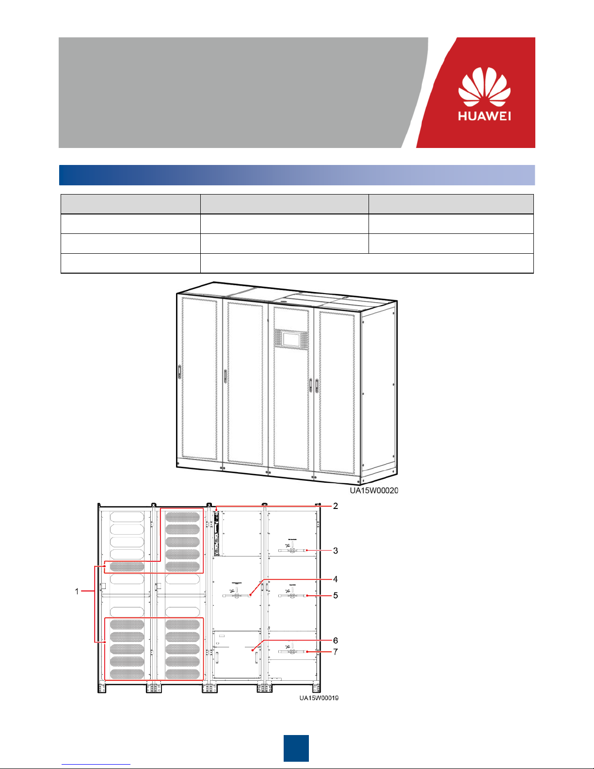
Model UPS5000-A-800K-F800-SC UPS5000-A-800K-F800-FC
Configuration Standard configuration Full configuration
Weight 1530 kg 1610 kg
Dimensions (H x W x D) 2000 mm x 2400 mm x 850 mm
(1) Power unit
(2) Control unit
(3) Mains input switch (only available
in the full configuration model)
(4) Maintenance bypass switch
(5) Output switch (only available in the
full configuration model)
(6) Bypass unit
(7) Bypass input switch (only available
in the full configuration model)
Power
cabinet
Bypass
cabinet
Power
cabinet
Bypass
cabinet
Page 2
2
1. Before installation, read the user manual carefully to get familiar with product information and
safety precautions.
2. Use insulated tools during installation.
3. Only engineers certified by Huawei or its agents are allowed to install, commission, and
maintain the UPS. Otherwise, personal injury or equipment damage may occur, and the UPS
faults caused are beyond the warranty scope of Huawei.
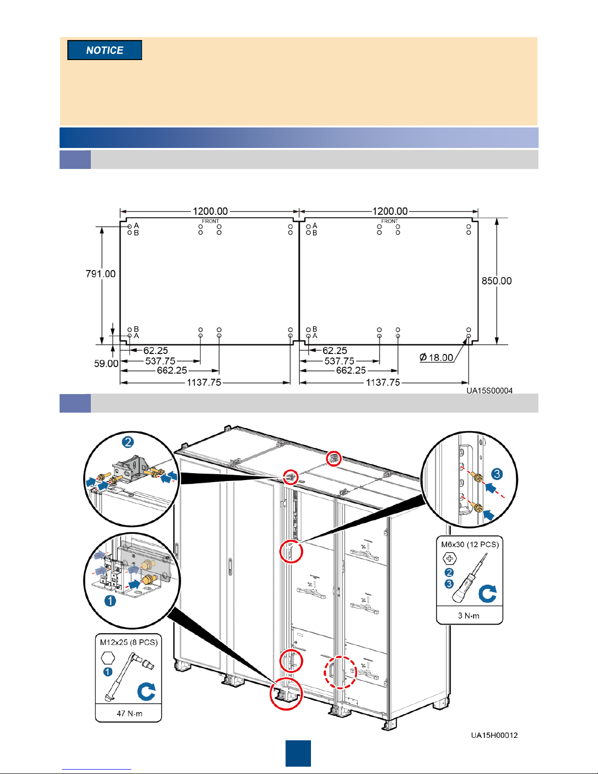
Install on the steel channel or floor. Determine the mounting hole positions (unit: mm) using a markingoff template, drill holes, and install expansion sleeves based on site requirements.
A: mounting holes on the steel channel B: mounting holes on the floor
2
Installing the UPS
Determining Installation Position
2.1
Combining Power Cabinets and Bypass Cabinets
2.2
1. Combine in the following sequence: bottom, top, and middle.
Page 3
3
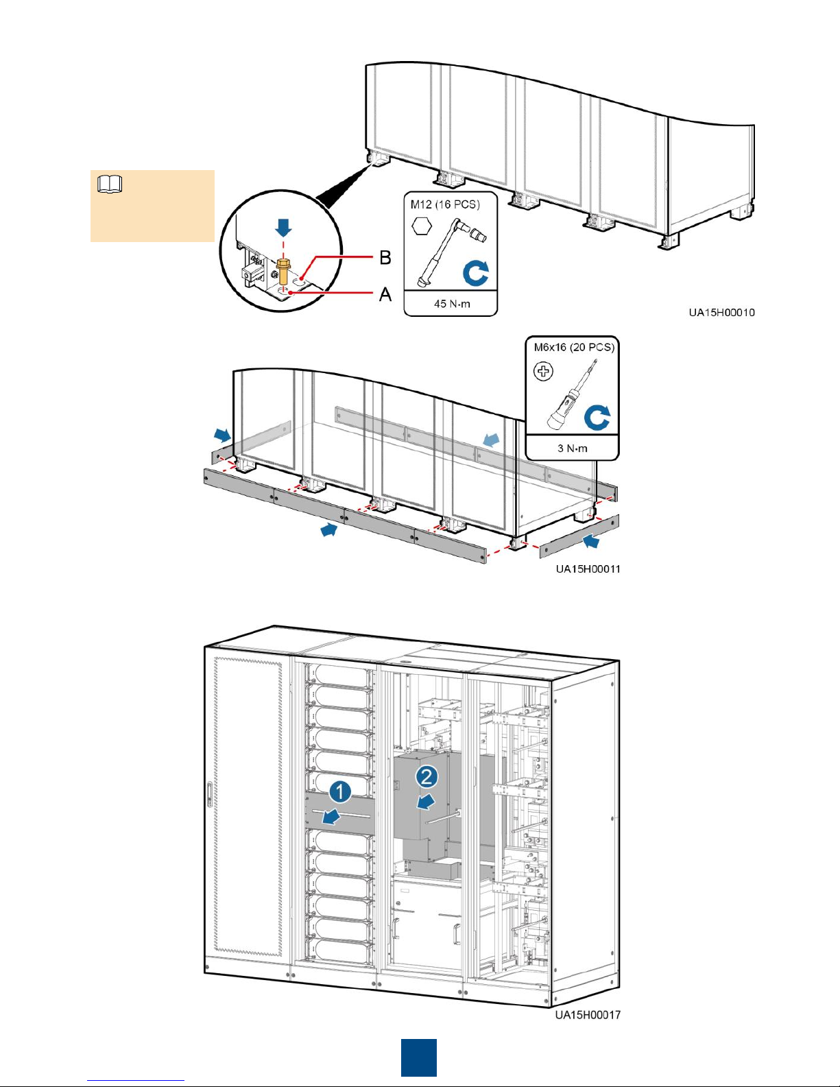
(A) Mounting holes on the steel
channel: M12x60 bolts
(B) Mounting holes on the floor:
M12x100 expansion bolts
2. Secure the UPS.
4. Remove the front cover and No. 10 protection panel from the bypass cabinet and the filler panel
from the power cabinet.
3. Install anchor baffle plates.
Bolts are not
included.
NOTE
Page 4

4
5. Cut off the cable ties bound between holes of copper bars No. 23, 24, 25, 26, and 30. Install
soft copper bars in the bypass cabinet and its adjacent power cabinet from inside out. Then,
install soft copper bars No. 52.
6. Reinstall the removed No. 10 protection panel on the bypass cabinet and the filler panel on
the power cabinet.
3
Connecting Cables
1. This document describes cable routing by removing the top cover when there are two mains
inputs.
2. In the case of single mains, you do not need to connect bypass input power cables and
remove short-circuit copper bars.
UPS Cable Connection Reference
• Prepare cables away from the cabinets to prevent scraps from falling inside. Cable scraps may
ignite and cause personal injury or device damage.
• After cables have been installed, clean the cabinets in a timely manner. Keep the cabinets and
surrounding environment clean and tidy.
• You need to prepare terminals onsite. The stripped length of the copper wire should be the
same as that of the part of the terminal that covers the conductor.
3.1
Page 5
5
The cabling route is for reference only. Connect cables based on site requirements.
NOTE
A UPS in standard configuration has only one switch cable (maintenance bypass switch). A
UPS in full configuration has three switch cables (mains input switch, maintenance bypass
switch, and bypass input switch). The following figure shows how to connect cables to a UPS in
full configuration.
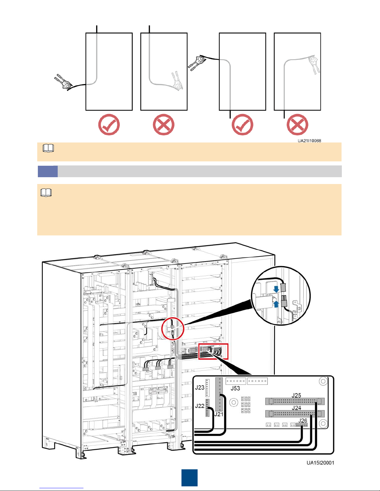
Connecting Signal Cables to Combined Cabinets
3.2
NOTE
Page 6
6
Bypass Cabinet
Cable Name
Bypass Cabinet Cable Label or
Number
Port Silk Screen on the Power
Cabinet Parallel Board or Cable
Number
Bypass unit DL37
cable
W301_J21
J21
W303_J24
J24
ECM 8
-pin cable
W305_J22
J22
ECM system
monitoring bus
W307_J25
J25
CT cable
W309_J26
J26
Switch cable
Full configuration: 04091625-06
Standard configuration: SW1310
04091626
-23
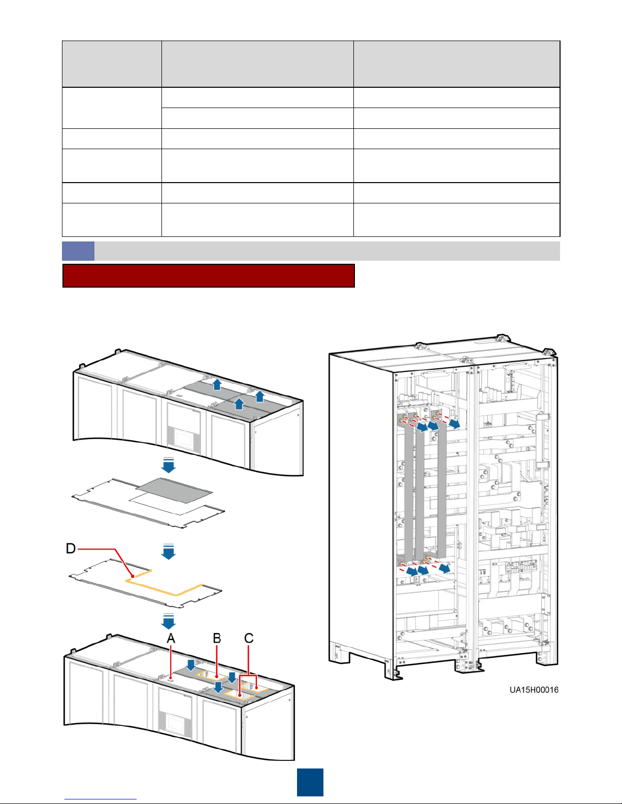
1. Remove the covers from the top of the cabinet, drill
holes in the covers for the power cables and battery
cables, attach grommet strips to the hole edges to
protect the cables, and reinstall the covers.
Connecting Power Cables and Signal Cables
3.3
Scenario 1: Routing Cables from the Top
(A) Signal cable hole
(B) Battery cable hole
(C) Power cable holes
(D) Grommet strip
2. Remove the copper bars between
the mains input and bypass input.
Page 7
7
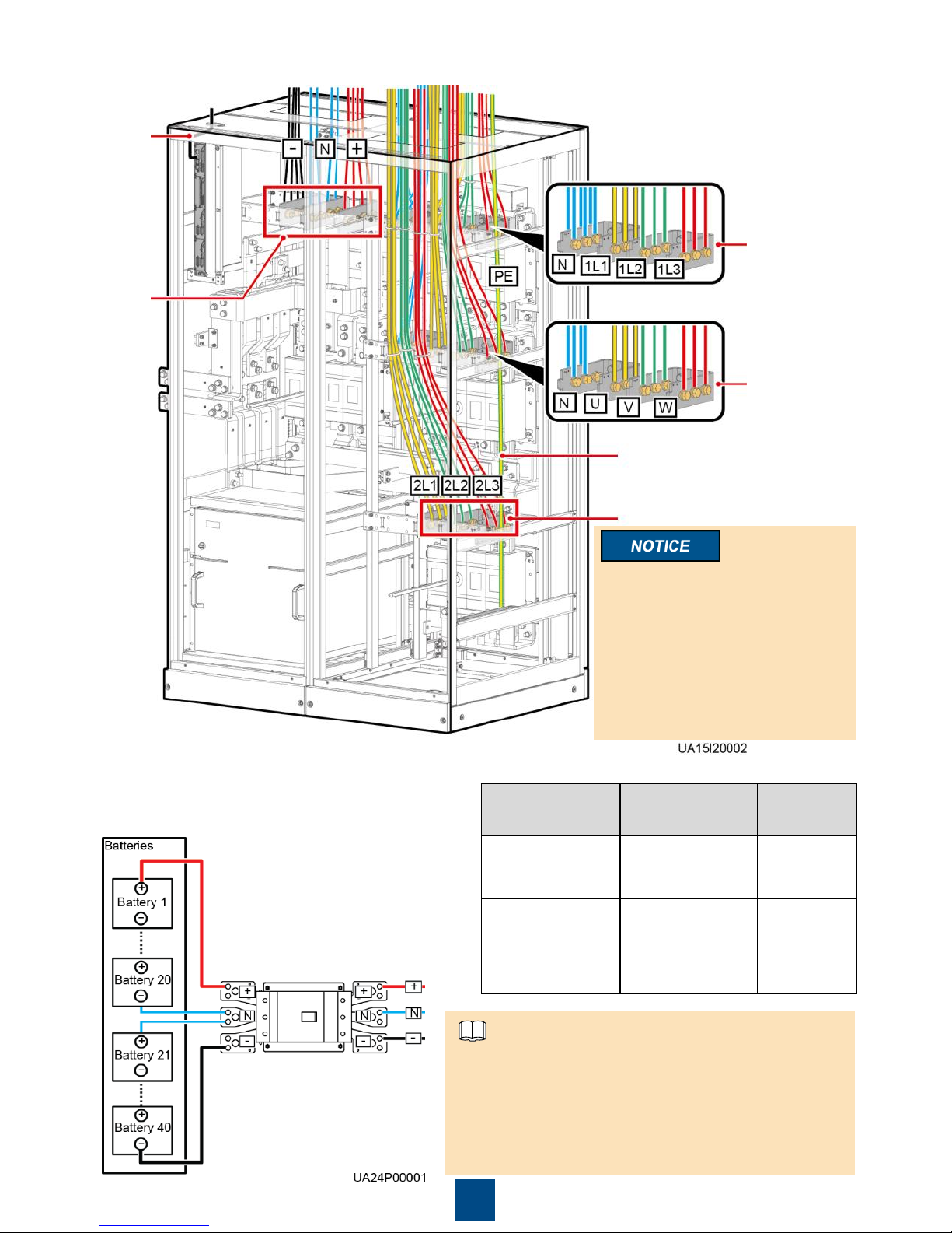
Bypass input power cable
(no need to connect in case
of only one mains input)
Output
power
cable
Mains input
power cable
Signal
cable
Battery
cable
3. Connect the ground cable, power cables, and signal cable.
The mains input and bypass
input share the N busbar.
The number of cables in the
figure is for reference only.
Because the switch extension
rod is sharp, exercise caution
when removing the connecting
copper bars to prevent personal
injury.
Port
Bolt
Specifications
Torque
Mains input M16x50 120 N·m
Bypass input M16x50 120 N·m
Battery input M16x50 120 N·m
Output M16x50 120 N·m
PE M12x35 47 N·m
NOTE
Ground
cable
The wire routed from the middle point between
positive and negative battery strings is the neutral
wire. Take a battery string consisting of 40 batteries
for example. The battery neutral wire is routed from
the middle between positive and negative battery
strings, each consisting of 20 batteries.
Page 8
8
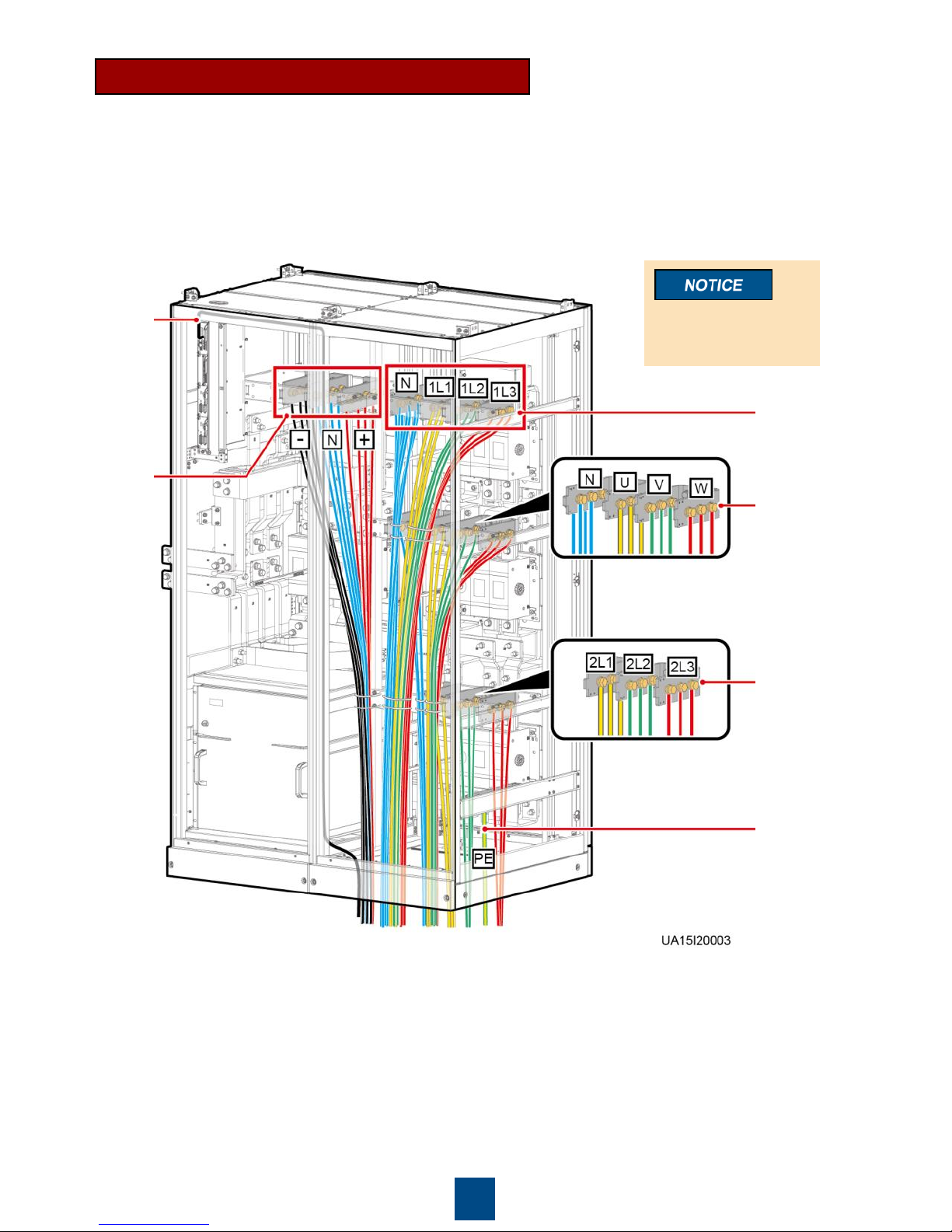
Scenario 2: Routing Cables from the Bottom
1. Remove the cable covers from the bottom of the cabinet, drill holes in the covers, attach
grommet strips to the hole edges to protect the cables, and reinstall the cable covers.
Output
power cable
Mains input
power cable
Ground
cable
Signal
cable
Battery
cable
The mains input
and bypass input
share the N busbar.
2. (Skip this step if the mains input and bypass input share a power source.) Remove the
copper bars between the mains input and bypass input.
3. Connect the ground cable, power cables, and signal cable.
Bypass input
power cable
(no need to
connect in
case of only
one mains
input)
Page 9
9
4
Verifying the Installation
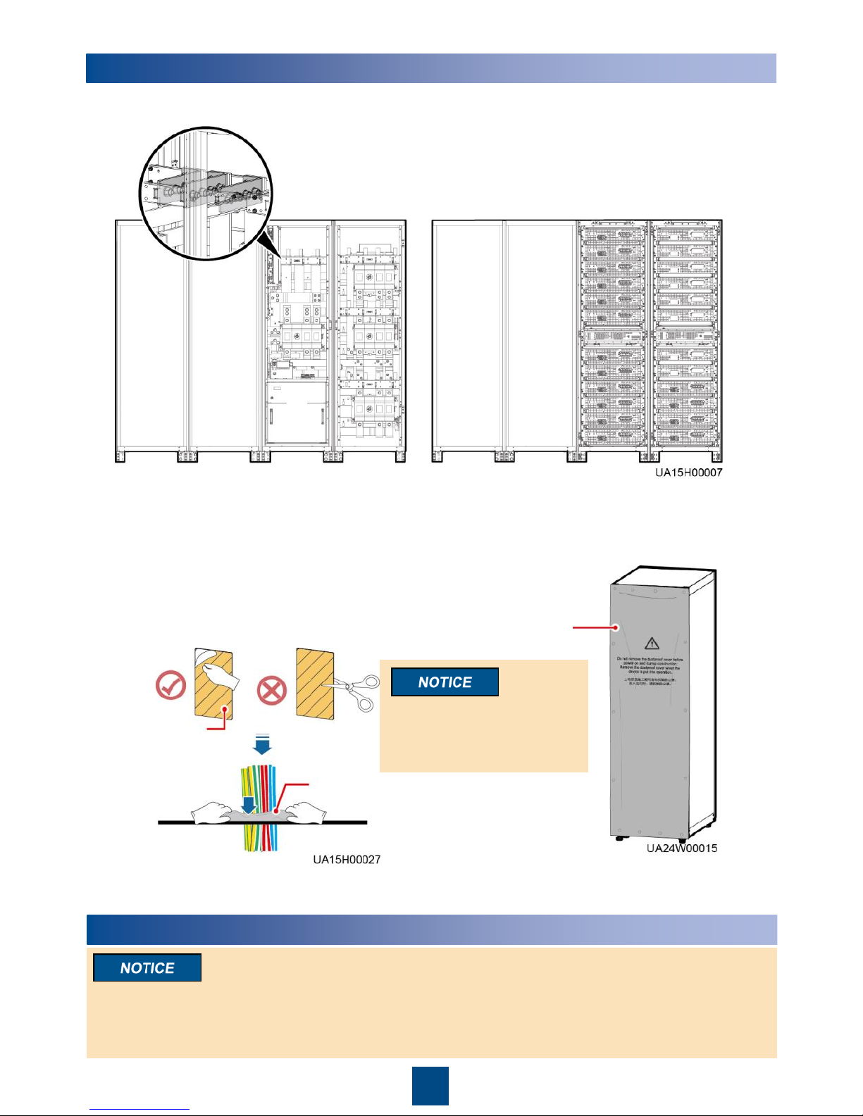
1. Check that there is no foreign matter at the top and bottom of the cabinets, copper bars, switches,
and the rear of units.
Front view
Rear view
2. After verifying the installation, reinstall all
the covers.
3. (Remove the paper protective film from the
sealing putty.) After routing cables and
verifying cable connections, seal the gap
between cables and the cabinet using
sealing putty.
Dustproof cover
4. Do not remove the dustproof cover before
power-on to prevent dust inside the UPS.
Sealing putty
Sealing putty must be used
as a whole and the gap can
be sealed only from the top.
Paper
protective film
5
Powering On and Starting the UPS
1. Before powering on the UPS, ensure that the UPS has passed all check items in the UPS5000
Commissioning and Acceptance Report and Chapter 4.
2. Measure the voltage and frequency of the UPS upstream input switch. The line voltage range is
138–485 V AC, and the frequency range is 40–70 Hz.
Page 10
10
Powering On the UPS
5.1
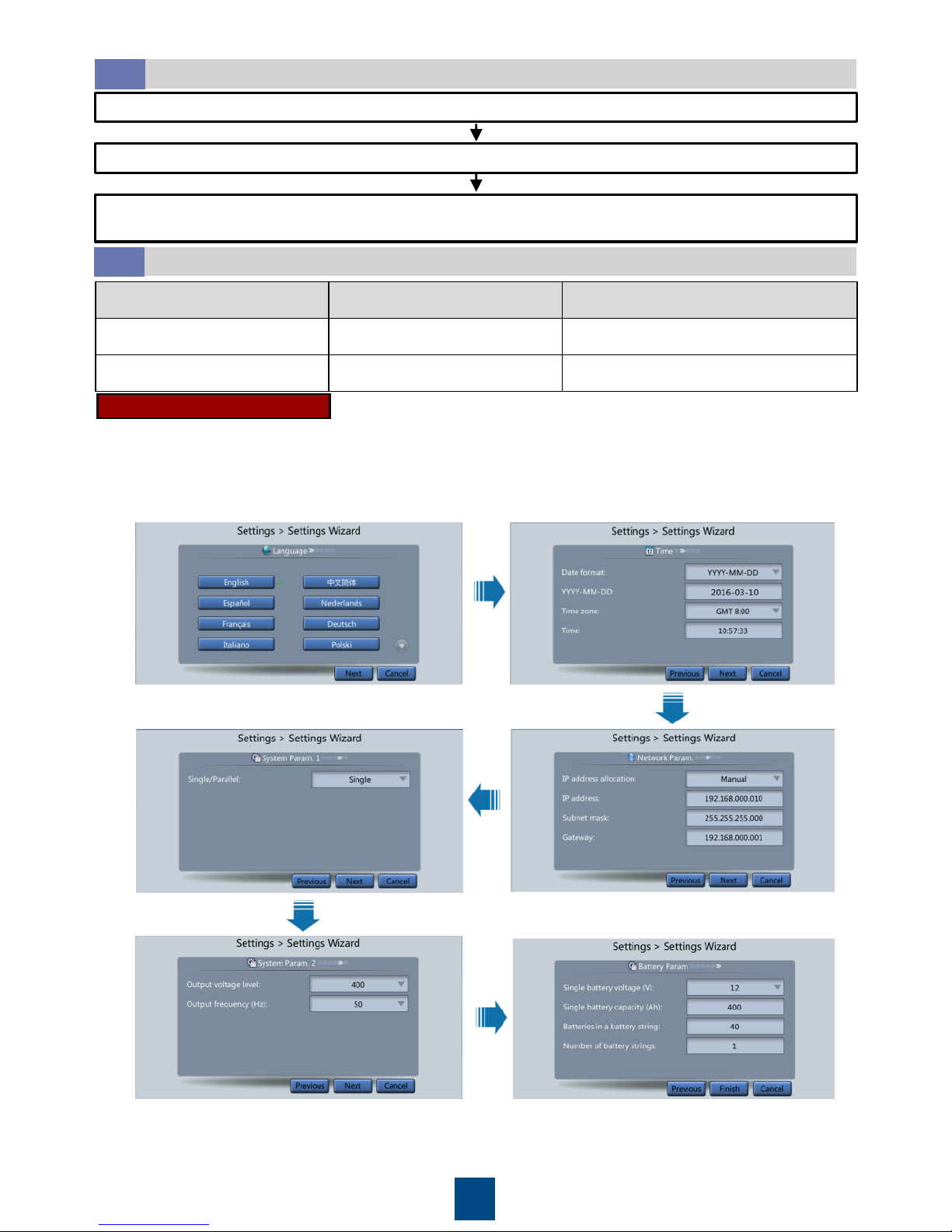
Close the upstream bypass and mains input switches.
(Full configuration model) Close the UPS bypass input switch, output switch, and mains input switch.
After the UPS is powered on, initialization begins. The MDU displays the Huawei logo and an
initialization progress bar.
Starting the Inverter
5.2
System User LCD Preset Password WebUI Preset Password
admin (system administrator) 000001 Changeme
operator (common user) 000001 Changeme
Initial Startup
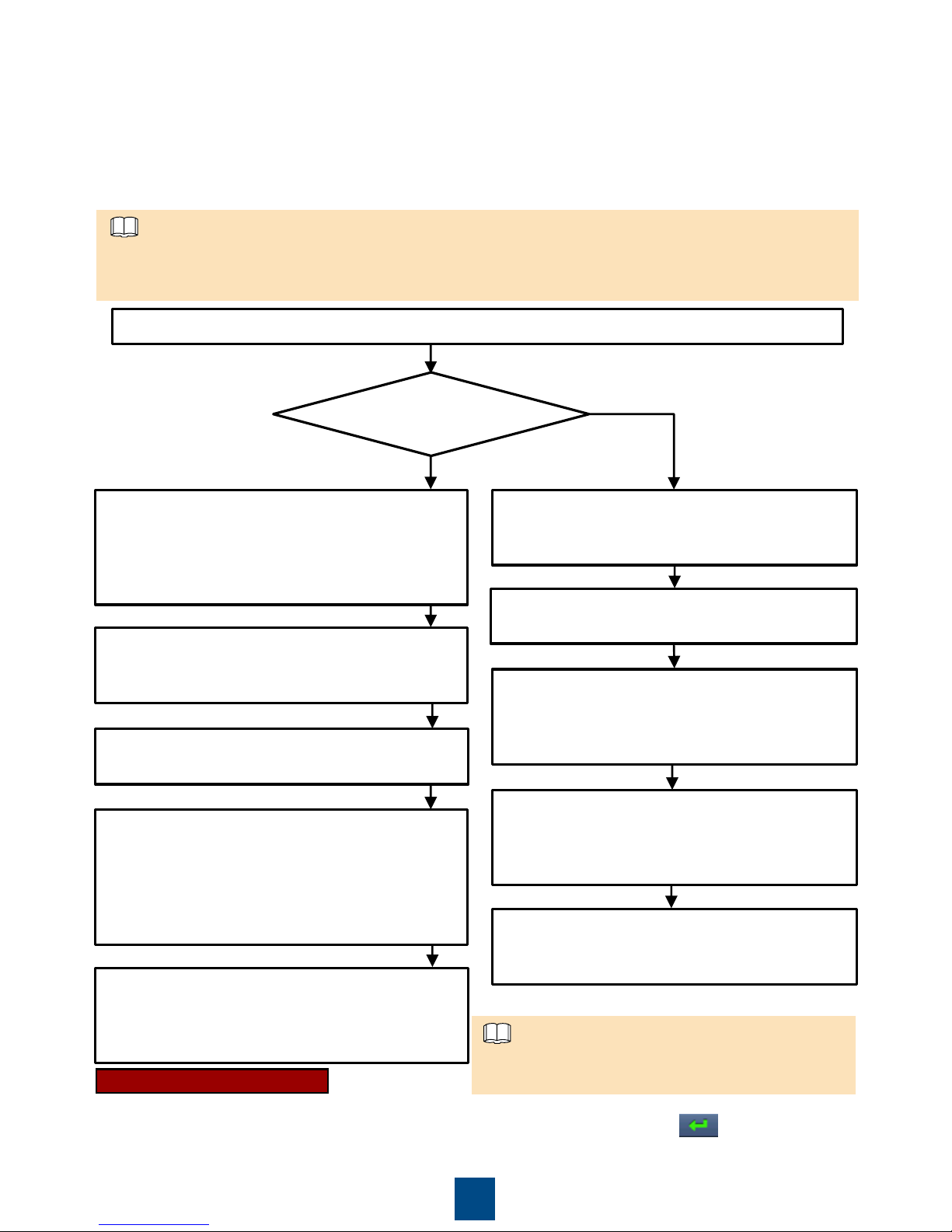
a) If this is the initial startup, set the language, time, date, network parameters, and system
parameters on the Settings Wizard screen.
Page 11
11
b) After you set parameters on the Settings Wizard screen, the MDU displays the Bypass mode
and No battery alarms, which do not need to be handled. If there is any other alarm, you need
to rectify the fault.
c) View the system running status diagram on the MDU to check that the UPS is working in
bypass mode.
d) Start the inverter on the app.
• The Service Expert app can be downloaded from Google Play and can run on Android.
• The port number is 443 by default and can be modified. If the UPS is managed using the app,
the port number must be set to 443.
NOTE
Download the mobile phone app (Service Expert).
On the app home screen, tap StartUp to
access the Set Startup screen. Set the Site
and Device Type as required, and connect
the device. Enter the UPS IP and Port as well
as the user name and password of the WebUI
account, and tap Login.
Enable the mobile phone WLAN, search for
the UPS WiFi signal, and connect to the WiFi
signal. The default value of SSID is UPS_WIFI.
Insert the WiFi module into the USB port on
the MDU. Set System Info > Settings >
Comm Settings > WiFi Settings on the MDU.
The initial WiFi password is Changeme by
default.
After login, tap Power-on password
activation on the screen. A message is
displayed, indicating whether to start the UPS.
Tap OK.
Enter Bar code and Verification code
obtained from the MDU on the Offline
Activation screen. Tap Generate PWD to
generate a startup password.
On the MDU, choose System Info >
Maintenance > Inv. ON and obtain the Bar
code and Verification.
Enter the generated password in the
password textbox on the MDU to start the
inverter.
Use the app to
start the inverter
online?
Yes
No, start the
inverter
offline
Open the Service Expert app on the mobile
phone.
Open the Service Expert app on the mobile
phone.
On the home screen of the app, tap StartUp
to access the Set Startup screen. Set Site
and Device Type as required, and tap
Offline Activation.
Non-initial Startup
a. Choose Common Functions from the main menu and tap Inv. ON.
b. In the displayed login window, enter the user name and password, and tap .
c. In the displayed dialog box, tap OK to start the inverter.
To ensure system security, change the LCD
and WebUI passwords after the first login.
NOTE
Page 12
12
6
Shutting Down the UPS
After you shut down the inverter, the UPS transfers to bypass mode if the bypass is normal; the
UPS supplies no power if the bypass is abnormal. Before shutting down the UPS, ensure that all
loads have been shut down.
Powering Off a Single UPS
6.2
Open the downstream output switch and battery string switch.
(Full configuration model) Open the UPS mains input switch, bypass input
switch, and output switch.
Open the upstream mains input and bypass input switches.
(Optional) Setting Parameters for the BCB Box
5.4
Powering On Loads
5.3
1. After the inverter starts, the UPS works in normal mode. The Bypass mode alarm disappears
from the MDU.
2. After confirming that the battery strings are properly connected, turn on the battery string input
circuit breaker. If there are multiple battery strings, turn on the circuit breaker for each battery
string and then turn on the general circuit breaker between battery strings and the UPS. The No
battery alarm disappears from the MDU.
3. Turn on the UPS downstream output switch to supply power to the loads.
1. On the main menu of the LCD, choose Common Functions and tap Inv. OFF.
2. In the displayed login window, enter the user name and password, and tap .
3. In the displayed dialog box, tap Yes to shut down the inverter.
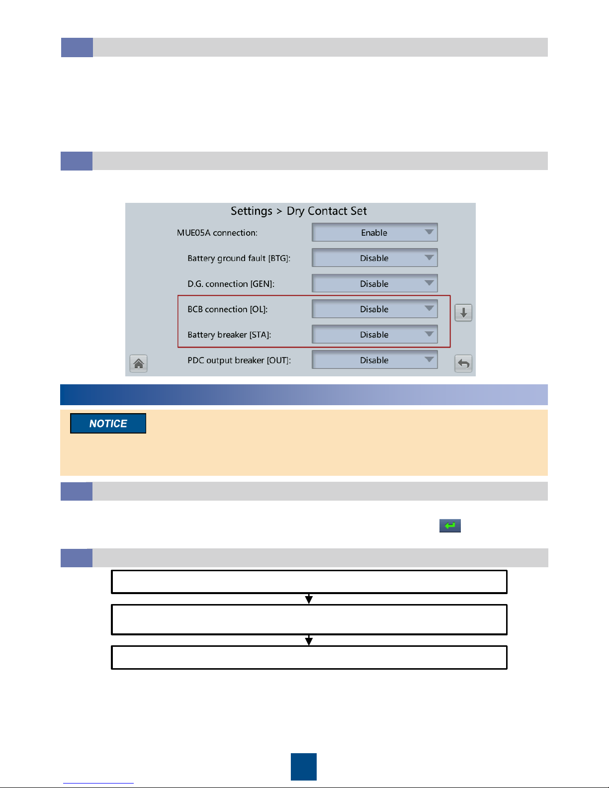
1. If a BCB box is configured, set MUE05A connection to Enable in Settings > Dry contacts Set,
and then set BCB connection [OL] and Battery breaker [STA] to Enable.
Shutting Down the Inverter to Transfer the UPS to Bypass Mode
6.1
Page 13
13
7
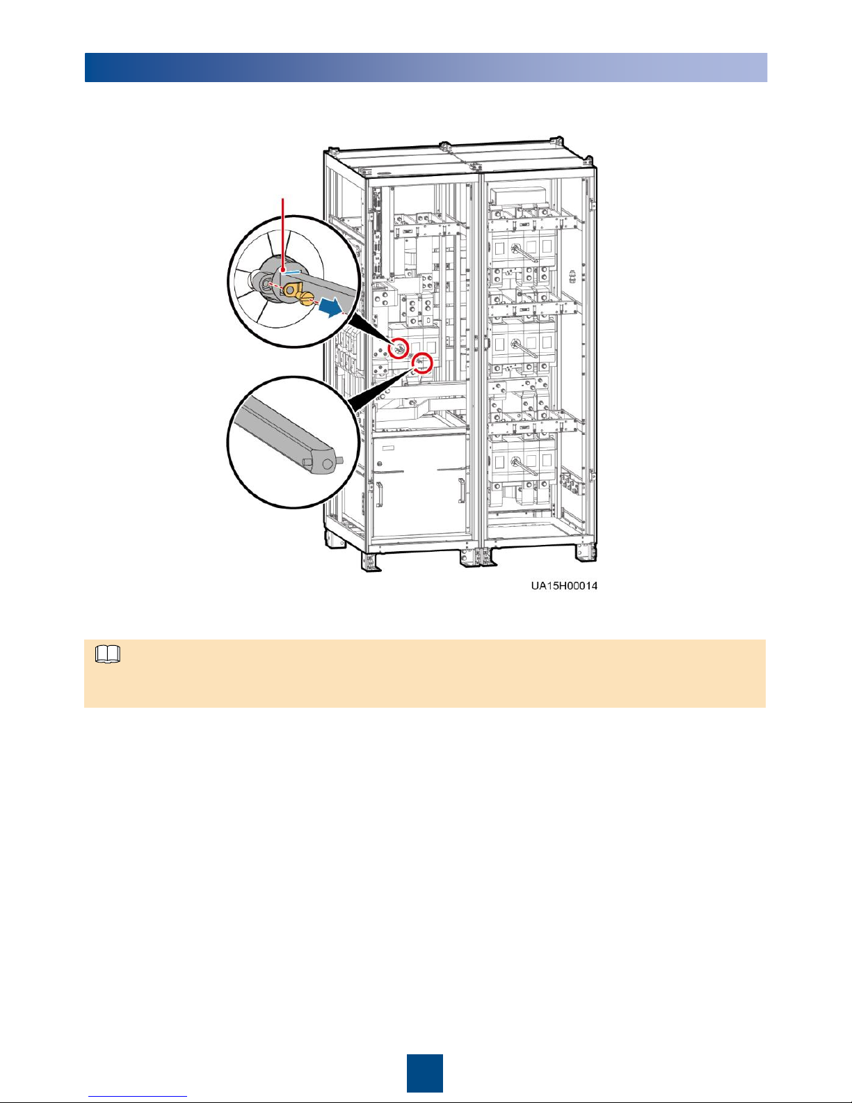
(Optional) Removing and Installing a Switch Extension Rod
Marked position
1. Remove the switch extension rod.
2. Install the switch extension rod.
Keep the dowel level, insert the switch extension rod to the marked position, place washers properly,
and tighten the slotted screw to install the switch extension rod.
NOTE
Huawei Technologies Co., Ltd.
Huawei Industrial Base, Bantian, Longgang
Shenzhen 518129 People's Republic of China
www.huawei.com
 Loading...