

Huawei UPS5000-A-30 kVA, UPS5000-A-40 kVA, UPS5000-A-80 kVA User Manual

UPS5000-A-30 kVA & 40 kVA & 80 kVA
User Manual
Issue
11
Date
2018-12-10
HUAWEI TECHNOLOGIES CO., LTD.

Issue 11 (2018-12-10)
Copyright © Huawei Technologies Co., Ltd.
i
Copyright © Huawei Technologies Co., Ltd. 2018. All rights reserved.
No part of this document may be reproduced or transmitted in any form or by any means without prior
written consent of Huawei Technologies Co., Ltd.
Trademarks and Permissions
and other Huawei trademarks are trademarks of Huawei Technologies Co., Ltd.
All other trademarks and trade names mentioned in this document are the property of their respective
holders.
Notice
The purchased products, services and features are stipulated by the contract made between Huawei and
the customer. All or part of the products, services and features described in this document may not be
within the purchase scope or the usage scope. Unless otherwise specified in the contract, all statements,
information, and recommendations in this document are provided "AS IS" without warranties, guarantees or
representations of any kind, either express or implied.
The information in this document is subject to change without notice. Every effort has been made in the
preparation of this document to ensure accuracy of the contents, but all statements, information, and
recommendations in this document do not constitute a warranty of any kind, express or implied.
Huawei Technologies Co., Ltd.
Address:
Huawei Industrial Base
Bantian, Longgang
Shenzhen 518129
People's Republic of China
Website:
http://e.huawei.com
UPS5000-A-30 kVA & 40 kVA & 80 kVA
User Manual
About This Document
Issue 11 (2018-12-10)
Copyright © Huawei Technologies Co., Ltd.
ii
Purpose
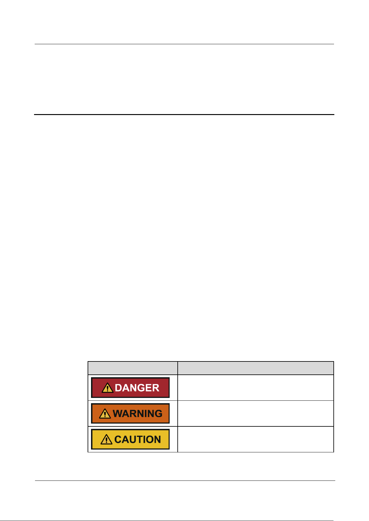
Symbol
Description
Indicates an imminently hazardous situation which, if
not avoided, will result in death or serious injury.
Indicates a potentially hazardous situation which, if not
avoided, could result in death or serious injury.
Indicates a potentially hazardous situation which, if not
avoided, may result in minor or moderate injury.
This document describes the high-frequency tower-mounted UPS5000-A-30 kVA & 40 kVA
& 80 kVA in terms of features, appearance, structure, working principle, technical
specifications, installation, operation, and maintenance. UPS is short for uninterruptible
power system. Unless otherwise specified, UPS refers to all the models described in this
document.
Intended Audience
About This Document
This document is intended for:
Sales engineers
Technical support engineers
System engineers
Hardware installation engineers
Commissioning engineers
Data configuration engineers
Maintenance engineers
Symbol Conventions
The symbols that may be found in this document are defined as follows.

UPS5000-A-30 kVA & 40 kVA & 80 kVA
User Manual
About This Document
Issue 11 (2018-12-10)
Copyright © Huawei Technologies Co., Ltd.
iii
Symbol
Description
Indicates a potentially hazardous situation which, if not
avoided, could result in equipment damage, data loss,
performance deterioration, or unanticipated results.
NOTICE is used to address practices not related to
personal injury.
Calls attention to important information, best practices
and tips.
NOTE is used to address information not related to
personal injury, equipment damage, and environment
deterioration.
Change History
Changes between document issues are cumulative. The latest document issue contains all the
changes made in earlier issues.
Issue 11(2018-12-10)
Update some MDU screenshots.
Issue 10 (2018-04-18)
This issue is the tenth official release, which incorporates the following change:
Updated the model specifications.
Issue 09 (2018-01-03)
This issue is the ninth official release, which incorporates the following changes:
Updated the output electrical specifications and typical configuration.
Updated the Monitoring screen image.
Issue 08 (2017-06-09)
This issue is the eighth official release, which incorporates the following changes:
Updated the Monitoring screen image.
Issue 07 (2016-12-03)
This issue is the seventh official release, which incorporates the following changes:
Updated the UPS front space reservation in section 3.1.1 "Site".
Added the section 3.2.7.1 "UPS Cable Connection Reference".
Added checking for foreign matters in section 3.4 "Installation Verification".
Added the section 5.1.5 "Setting ECO Mode" and the section 5.1.6 "Testing Batteries".

UPS5000-A-30 kVA & 40 kVA & 80 kVA
User Manual
About This Document
Issue 11 (2018-12-10)
Copyright © Huawei Technologies Co., Ltd.
iv
Updated the section 6 "Routine Maintenance".
Added the specifications of the internal circuit breaker in the section 8 "Technical
Specifications".
Issue 06 (2015-06-26)
This issue is the sixth official release, which incorporates the following changes:
Updated the Monitoring screen image.
Issue 05 (2014-09-26)
This issue is the fifth official release, which incorporates the following changes:
Added the features of four parallel systems and the battery monitoring unit (BMU).
Issue 04 (2014-07-16)
This issue is the fourth official release, which incorporates the following changes:
Updated section 1 Precautions.
Issue 03 (2014-01-20)
This issue is the third official release, which incorporates the following changes:
Updated section 1 Precautions.
Updated the secured installation for the UPS5000-A-60 kVA/80 kVA/120 kVA in section
3.2.2.
Updated section 7 Troubleshooting Alarm List.
Issue 02 (2013-11-18)
This is the second official release, which incorporates the following changes:
Added figures of OT and DT terminals for the UPS5000-A and tables that list their
specifications in section 3.1.3.
Issue 01(2013-11-05)
This is the first release.

UPS5000-A-30 kVA & 40 kVA & 80 kVA
User Manual
Contents
Issue 11 (2018-12-10)
Copyright © Huawei Technologies Co., Ltd.
v
Contents
About This Document .................................................................................................................... ii
1 Safety Precautions ......................................................................................................................... 1
1.1 General Safety .............................................................................................................................................................. 1
1.2 Electrical Safety ............................................................................................................................................................ 3
1.3 Operating Environment................................................................................................................................................. 6
1.4 Battery Safety ............................................................................................................................................................... 6
1.5 Mechanical Safety ........................................................................................................................................................ 8
1.6 Laying Out Cables ........................................................................................................................................................ 9
1.7 Information About Foreign Objects near UPS Equipment Installation ....................................................................... 10
2 Overview ....................................................................................................................................... 12
2.1 Model Description ...................................................................................................................................................... 12
2.2 Working Principles...................................................................................................................................................... 12
2.2.1 Conceptual Diagram ................................................................................................................................................ 12
2.2.2 Working Modes ........................................................................................................................................................ 13
2.2.2.1 Normal Mode ........................................................................................................................................................ 13
2.2.2.2 Bypass Mode ........................................................................................................................................................ 14
2.2.2.3 Battery Mode ........................................................................................................................................................ 14
2.2.2.4 Maintenance Bypass Mode ................................................................................................................................... 15
2.2.2.5 ECO Mode ............................................................................................................................................................ 15
2.3 Product Description .................................................................................................................................................... 17
2.3.1 Appearance .............................................................................................................................................................. 17
2.3.2 Product Structure ..................................................................................................................................................... 18
2.3.2.1 30 kVA/40 kVA UPS ............................................................................................................................................. 18
2.3.2.2 80kVA UPS ................................ ................................................................ ........................................................... 22
2.3.3 Control Port ............................................................................................................................................................. 23
2.4 Typical configurations ................................................................................................................................................ 27
2.4.1 Single UPS ............................................................................................................................................................... 28
2.4.2 Parallel System ........................................................................................................................................................ 28
2.4.3 Dual-Bus System ..................................................................................................................................................... 29
2.5 Optional Components ................................................................................................................................................. 30
3 Installation.................................................................................................................................... 32
3.1 Installation Preparations ............................................................................................................................................. 32

UPS5000-A-30 kVA & 40 kVA & 80 kVA
User Manual
Contents
Issue 11 (2018-12-10)
Copyright © Huawei Technologies Co., Ltd.
vi
3.1.1 Site ........................................................................................................................................................................... 32
3.1.2 Tools and Instruments .............................................................................................................................................. 35
3.1.3 Power Cables ........................................................................................................................................................... 37
3.1.4 Unpacking and Checking ......................................................................................................................................... 42
3.1.4.1 30 kVA/40 kVA UPS ............................................................................................................................................. 43
3.1.4.2 80 kVA UPS .......................................................................................................................................................... 44
3.2 Installing a Single UPS ............................................................................................................................................... 48
3.2.1 Installing the UPS5000-A-30 kVA/40 kVA ............................................................................................................. 48
3.2.2 Installing the UPS5000-A-80 kVA .......................................................................................................................... 59
3.2.3 (Optional) Installing Antiseismic Kits ..................................................................................................................... 71
3.2.4 (Optional) Installing a Battery Monitoring Unit ...................................................................................................... 72
3.2.5 Installing Batteries ................................................................................................................................................... 74
3.2.6 UPS Cable Connection Reference ........................................................................................................................... 75
3.2.7 Routing Cables......................................................................................................................................................... 76
3.2.7.1 Cable Routes ......................................................................................................................................................... 76
3.2.7.2 Connecting Ground Cables ................................................................................................................................... 78
3.2.7.3 Connecting AC Input Power Cables ..................................................................................................................... 80
3.2.7.4 Connecting AC Output Power Cables ................................................................................................................... 84
3.2.7.5 Connecting Battery Cables ................................................................................................................................... 85
3.2.8 Remote EPO ............................................................................................................................................................ 87
3.2.9 Connecting Communications Cables ....................................................................................................................... 88
3.3 Installing a Parallel System ......................................................................................................................................... 88
3.3.1 Connecting Power Cables ........................................................................................................................................ 88
3.3.2 Connecting Signal Cables ........................................................................................................................................ 92
3.4 Installation Verification ............................................................................................................................................... 94
4 LCD and WebUI .......................................................................................................................... 99
4.1 MDU ........................................................................................................................................................................... 99
4.2 LCD ................................................................ ................................ ................................................................ .......... 101
4.2.1 Overview ............................................................................................................................................................... 101
4.2.2 Status Screen .......................................................................................................................................................... 102
4.2.3 Alarms .................................................................................................................................................................... 105
4.2.4 Settings Screen....................................................................................................................................................... 106
4.2.5 Control ................................................................................................................................................................... 120
4.2.6 About Screen .......................................................................................................................................................... 122
4.3 WebUI ....................................................................................................................................................................... 122
4.3.1 Login ...................................................................................................................................................................... 122
4.3.2 Monitoring Page .................................................................................................................................................... 124
4.3.2.1 Parameter Settings .............................................................................................................................................. 125
4.3.2.2 Communications Settings ................................................................................................................................... 132
4.3.2.3 Control ................................................................................................................................................................ 132
4.3.3 Query Page ............................................................................................................................................................ 133

UPS5000-A-30 kVA & 40 kVA & 80 kVA
User Manual
Contents
Issue 11 (2018-12-10)
Copyright © Huawei Technologies Co., Ltd.
vii
4.3.3.1 Historical Alarms Page ....................................................................................................................................... 133
4.3.3.2 Logs Page ........................................................................................................................................................... 133
4.3.4 Config. Page .......................................................................................................................................................... 134
4.3.4.1 User Management ............................................................................................................................................... 134
4.3.4.2 Site Config. ......................................................................................................................................................... 134
4.3.4.3 RCCMD .............................................................................................................................................................. 136
4.3.4.4 Managing the UPS by Using the NMS Complying with RFC1628 Standard ..................................................... 145
4.3.5 Protecting the Server by Using the RCCMD Software .......................................................................................... 146
4.3.5.1 Introduction to the Software ............................................................................................................................... 146
4.3.5.2 RCCMD Event Shutdown and Message Sending ............................................................................................... 147
4.3.5.3 UPS Alive Check Function ................................................................................................................................. 148
5 Operations .................................................................................................................................. 151
5.1 Powering On and Starting the UPS ........................................................................................................................... 151
5.2 Shutting Down and Powering Off the UPS .............................................................................................................. 155
5.3 Starting the UPS in Battery Mode ............................................................................................................................ 156
5.4 Transferring to Bypass Mode .................................................................................................................................... 157
5.5 Setting ECO Mode .................................................................................................................................................... 157
5.6 Testing Batteries ....................................................................................................................................................... 158
5.6.1 Forced Equalized Charging Test ............................................................................................................................ 158
5.6.2 Shallow Discharge Test .......................................................................................................................................... 159
5.6.3 Capacity Test.......................................................................................................................................................... 161
5.6.4 Test Data Download ............................................................................................................................................... 162
5.7 Transferring to Maintenance Bypass Mode .............................................................................................................. 162
5.8 Transferring from Maintenance Bypass Mode to Normal Mode .............................................................................. 165
5.9 Performing EPO........................................................................................................................................................ 166
5.10 Clearing the EPO State ........................................................................................................................................... 167
6 Routine Maintenance ............................................................................................................... 169
6.1 UPS Maintenance ..................................................................................................................................................... 169
6.1.1 Monthly Maintenance ............................................................................................................................................ 169
6.1.2 Quarterly Maintenance .......................................................................................................................................... 170
6.1.3 Annual Maintenance .............................................................................................................................................. 170
6.2 Battery Maintenance ................................................................................................................................................. 171
6.2.1 Precautions for Battery Maintenance ..................................................................................................................... 172
6.2.2 Monthly Maintenance ............................................................................................................................................ 172
6.2.3 Quarterly Maintenance .......................................................................................................................................... 173
6.2.4 Annual Maintenance .............................................................................................................................................. 174
7 Troubleshooting ........................................................................................................................ 175
8 Technical Specifications .......................................................................................................... 178
8.1 Physical Specifications ............................................................................................................................................. 178
8.2 Internal Switch Parameters ....................................................................................................................................... 178

UPS5000-A-30 kVA & 40 kVA & 80 kVA
User Manual
Contents
Issue 11 (2018-12-10)
Copyright © Huawei Technologies Co., Ltd.
viii
8.3 Environmental Specifications ................................................................................................................................... 178
8.4 Safety Regulations and EMC .................................................................................................................................... 179
8.5 Mains Input Electrical Specifications ....................................................................................................................... 179
8.6 Bypass Input Electrical Specifications ................................................................ ................................ ...................... 180
8.7 Battery Specifications ............................................................................................................................................... 180
8.8 Output Electrical Specifications ............................................................................................................................... 181
8.9 System Electrical Specifications ............................................................................................................................... 181
A Menu Hierarchy ....................................................................................................................... 182
A.1 LCD Menus ............................................................................................................................................................. 182
A.2 Menus on the WebUI ............................................................................................................................................... 183
B Alarm List................................................................................................................................... 186
C Acronyms and Abbreviations ................................................................................................ 200

UPS5000-A-30 kVA & 40 kVA & 80 kVA
User Manual
1 Safety Precautions
Issue 11 (2018-12-10)
Copyright © Huawei Technologies Co., Ltd.
1
1.1 General Safety
This section describes safety precautions to consider before installing, maintaining, and
operating the UPS.
1 Safety Precautions
Declaration
To minimize the risk of personal injury and damage to equipment, read and follow all the
precautions in this document before performing any operation. The "DANGER",
"WARNING", "CAUTION", and "NOTICE" statements in this document are only
supplemental and do not represent all the safety instructions.
Only trained and qualified personnel are allowed to install, operate, and maintain Huawei
equipment.
Follow the precautions and special safety instructions provided by Huawei when operating
Huawei products. Huawei will not be liable for any consequences that are caused due to
violations regarding general safety regulations and equipment design, production, and usage
safety standards.
Huawei does not take responsibilities for the following situations:
Operation under severe environments that are not specified in this document.
Installation or use in environments that are not specified in related international
standards.
Unauthorized product changes and software code modification.
Operations not complying with the operation instructions and safety precautions in this
document.
Damage caused by extreme natural environments.
Damage caused by using batteries provided by Huawei for non-Huawei UPSs.
Damage caused by using batteries not provided by Huawei.

UPS5000-A-30 kVA & 40 kVA & 80 kVA
User Manual
1 Safety Precautions
Issue 11 (2018-12-10)
Copyright © Huawei Technologies Co., Ltd.
2
Power Grid Requirements
A standard UPS can connect to a three-phase, five-wire (L1, L2, L3, N, PE) TT, TN-C, TN-S,
and TN-C-S AC power distribution system (IEC60364-1).
Local Laws and Regulations
Equipment operations must comply with local laws and regulations. The safety instructions in
this document are only supplemental to local safety regulations.
Personal Requirements
Only Huawei engineers or engineers certified by Huawei are allowed to perform UPS
commissioning and maintenance. Otherwise, human injury or equipment damage may occur,
and any resulting UPS faults will be beyond warranty scope.
Personnel who plan to install or maintain Huawei equipment must receive thorough training,
understand all necessary safety precautions, and master the correct operation methods.
Trained and qualified personnel, or personnel certified or authorized by Huawei are:
Allowed to install, operate, and maintain the equipment.
Allowed to remove safety facilities and inspect the equipment.
Allowed to replace or change the devices or components (including software).
Operation personnel must report faults or errors that might cause serious safety issues to
related owners.
This product should be installed and used according to the installation and technical,
specification requirements found in this manual. Otherwise, the product may be damaged,
and the resulting product exceptions or component damage will be beyond the warranty
scope.
Grounding Requirements
Devices to be grounded (excluding the energy storage unit) must meet the following
requirements:
When installing a device, install the ground cable first. When removing a device, remove
the ground cable at the very end.
Do not damage the ground conductor.
Do not operate devices if the ground conductor is not installed. Before operating a device,
check the electrical connection of the device to ensure that it is securely grounded.
Personal Safety
Do not operate the product, or handle cables, during thunderstorms.
To avoid electric shocks, do not connect safety extra-low voltage (SELV) circuits to
telecommunication network voltage (TNV) circuits.
Before operating a device, wear electrostatic discharge (ESD) clothes, ESD gloves, and
an ESD wrist strap. Remove any conductors (such as jewelry or watches) before the
operation to avoid electric shocks or burns.

UPS5000-A-30 kVA & 40 kVA & 80 kVA
User Manual
1 Safety Precautions
Issue 11 (2018-12-10)
Copyright © Huawei Technologies Co., Ltd.
3
Device Safety
In the case of fire, leave the building or the equipment room immediately, and turn on the
fire alarm bell or make an emergency call. Never enter the building on fire in any case.
If the cabinet provides an ESD jack, wear an ESD wrist strap and insert the ground
terminal of the ESD wrist strap into the jack.
Ensure all switches are turned to OFF during device installation.
Power on the UPS only after authorized engineers arrive at the site.
If a C2 UPS is used in residential areas, additional measures must be taken to prevent
radio frequency interferences.
If the UPS is used for life-supporting medical apparatus and facilities such as lifts where
adequate care has to be taken to ensure personal safety, discuss with the manufacturer in
advance about the applicability, settings, management, and maintenance of the UPS,
which require special considerations during design.
Before operation, ensure that the device is firmly anchored to the floor or other solid
objects, such as a wall or an installation rack.
Ensure ventilation vents are unblocked while the system is operating.
Before powering on the device, ensure that all the screws inside it are securely tightened
and will not fall off during operation.
After the installation, remove packing materials from the equipment area.
Replace danger signs that have worn out or are unreadable.
A UPS can be used to serve resistive-capacitive loads, resistive loads, and
micro-inductive loads. It is recommended that a UPS not be used for pure capacitive
loads, pure inductive loads, and half-wave rectification loads. It does not apply to energy
feedback loads.
Do not alter the UPS internal structure or installation procedure unless consent from the
manufacturer is given.
Never use water to clean electrical components inside or outside the UPS.
Do not drill holes into a cabinet.
1.2 Electrical Safety
High Voltage
The high voltage power supply provides power for the device operation. Direct or indirect
contact with high voltage power sources may result in fatal injury.
Non-standard or incorrect high voltage operations may result in fire and electric shocks.
The personnel who install the AC facility must be qualified to perform high voltage and
AC operations.
When selecting, connecting, and routing power cables, ensure compliance with local
laws and regulations.

UPS5000-A-30 kVA & 40 kVA & 80 kVA
User Manual
1 Safety Precautions
Issue 11 (2018-12-10)
Copyright © Huawei Technologies Co., Ltd.
4
When operating the AC power supply facility, ensure compliance with local laws and
regulations.
Before connecting cables to the UPS, ensure that the input power and mains power
distribution switches and output power distribution switch are turned off.
Use only dedicated tools during high voltage and AC operations.
If the operation is performed in a damp environment, ensure that the device is dry. When
water is found in the rack or the rack is damp, switch off the power supply immediately.
High Leakage Current
Ground a device before powering it on. Otherwise, personal injury or device damage may
occur.
If a "high leakage current" tag is attached to the panel of the device, ground the protective
ground terminal on the device enclosure before connecting the AC power supply to
prevent electric shocks.
The UPS can generate high leakage currents. Using a circuit breaker that has the leakage
current protection function is not recommended.
Power Cable
Fuse
Do not install or remove power cables when the device is on. Transient contact between the
core of the power cable and the conductor may generate electric arcs or sparks, which may
cause fire or damage eyesight.
Before moving or reconnecting the UPS, disconnect the mains and batteries, open the
output power distribution switch, and wait a period of at least 5 minutes after the UPS
completely powers off. Otherwise, electric shocks may occur.
Before installing or removing the power cable, open the power switch.
Before connecting a power cable, check that its label is correct.
If a fuse needs replacing, ensure the new fuse is of the same type and specifications so that the
system runs safely.
Backfeed Protection Dry Contact
The UPS can be configured with a backfeed protection dry contact to work with an external
automatic circuit breaker, preventing the voltage from flowing back to input terminals over
UPS5000-A-30 kVA & 40 kVA & 80 kVA
User Manual
1 Safety Precautions
Issue 11 (2018-12-10)
Copyright © Huawei Technologies Co., Ltd.
5
static bypass circuits. If device installation and maintenance personnel do not need to use
backfeed protection, paste labels on the external bypass input circuit breakers informing that
the circuit is connected to the UPS. Disconnect the device from the UPS before performing
operations on the circuit.
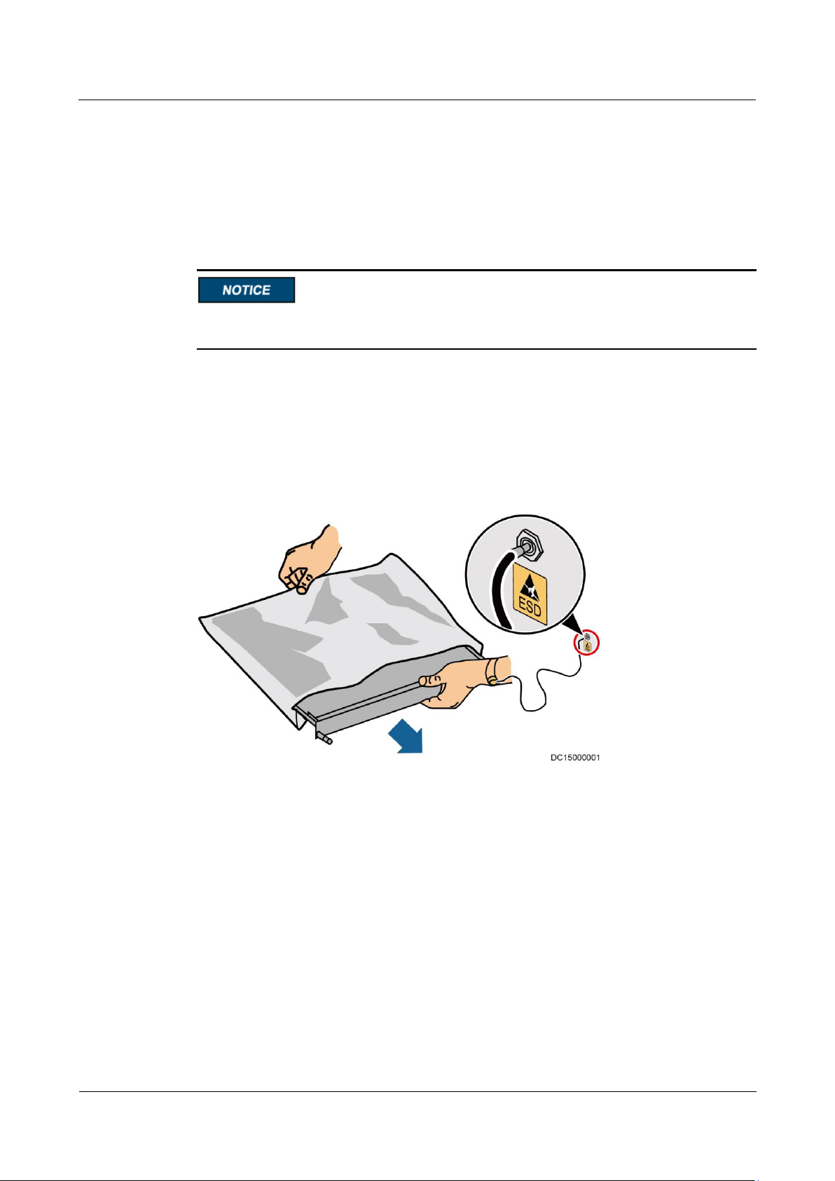
Electrostatic Discharge
Static electricity generated by human bodies may damage the electrostatic-sensitive
components on boards, for example, the large-scale integrated (LSI) circuits.
Wear a pair of ESD gloves or a well-grounded ESD wrist strap when touching the device
or handling boards or application-specific integrated circuits (ASICs).
When holding a board, hold its edge without touching any components, especially chips.
Package boards with ESD packaging materials before storing or transporting them.
Figure 1-1 shows how to wear an ESD wrist strap.
Figure 1-1 Wearing an ESD wrist strap
Liquid Prevention
Do not place the product under areas prone to water leakage, such as near air conditioner
vents, ventilation vents, or feeder windows of the equipment room. Ensure that there is
no condensation inside the product or equipment room. Ensure that no liquid enters the
product. Otherwise, short circuits will occur and may result in serious injury or death.
If any liquid is detected inside the product, immediately disconnect the power supply and
contact the administrator.

UPS5000-A-30 kVA & 40 kVA & 80 kVA
User Manual
1 Safety Precautions
Issue 11 (2018-12-10)
Copyright © Huawei Technologies Co., Ltd.
6
1.3 Operating Environment
The UPS is used for commercial and industrial purposes only. It cannot be used as a power
supply for life support devices.
The TIER4 or TIER3 power supply architecture specified in TIA942, that is, dual power
supply routes, must be used in the power supply systems that are crucial to major economic
interests or order of public places, such as the national computing center, military command
system, emergency command center, railway signal system and control center, civil aviation
air traffic control center, airport command center, financial clearing center, and transaction
center.
The UPS operating environment must meet the requirements for the climate indicator,
mechanically active substance indicator, and chemically active substance indicator in ETSI
EN 300 019-1 class 3.6.
Do not expose the equipment or perform any operations in an environment with flammable or
explosive gas, or smoke.
Any operation on any electrical device in an environment that has flammable air can cause
extreme danger. Strictly obey the operating environmental requirements specified in related
use manuals when using or storing the device.
Do not use the UPS in the following environments:
Environment containing flammable gases, corrosive gases, abnormal vibrations, and
impacts.
Non-confined environment near the ocean (0–3.7 km) and indoor or semi-indoor
environment where the temperature and humidity are not controllable, such as a simple
equipment room near the ocean, citizen house, garage, corridor, direct ventilation cabinet,
house with only the roof, railway station platform, gymnasium, aquarium, and so on.
1.4 Battery Safety
This section describes precautions for operating batteries.
Before operating batteries, carefully read the safety precautions to ensure correct battery
handling and connection is performed, and personal safety is managed.

UPS5000-A-30 kVA & 40 kVA & 80 kVA
User Manual
1 Safety Precautions
Issue 11 (2018-12-10)
Copyright © Huawei Technologies Co., Ltd.
7
To ensure battery safety and efficient battery management, use the batteries delivered with
the UPS. Huawei shall not be responsible for battery damage caused by using non-Huawei
batteries for Huawei UPSs.
Ensure lead-acid battery handling is in accordance with local regulations.
Incorrect handling of batteries may cause hazards. When operating batteries, avoid
battery short circuits and electrolyte overflow or leakage.
Electrolyte overflow may damage the device by corroding metal parts and circuit boards,
and ultimately damaging the circuit boards.
Short circuits caused by incorrect operations may cause serious injuries due to high
power of batteries.
Do not reversely connect positive and negative battery terminals.
Use batteries of the specified type. Otherwise, the batteries may be damaged.
Check battery connections periodically to ensure that all screws are securely tightened.
Install or store batteries in clean, cool, and dry environments.
Do not decompose, transform, or damage batteries. Otherwise, battery short circuit,
electrolyte leakage, and even personal injury may occur.
Preventative Measures
When installing and maintaining batteries, pay attention to the following points:
Use dedicated insulated tools.
Take measures to protect eyes, such as using eye protection devices.
Avoid skin contact with electrolyte overflow. Wear rubber gloves and protective
clothing.
When handling a battery, ensure that its electrodes always point upward. Do not tilt or
overturn batteries.
Switch off the power supply during installation and maintenance.
Short Circuit
Battery short circuits may cause personal injury. The high transient current generated by a
short circuit may release a surge of power and cause a fire.
To avoid battery short circuits, do not maintain batteries while they are in use.
Harmful Gas
UPS5000-A-30 kVA & 40 kVA & 80 kVA
User Manual
1 Safety Precautions
Issue 11 (2018-12-10)
Copyright © Huawei Technologies Co., Ltd.
8
Do not use unsealed lead-acid batteries. Lead-acid batteries emit flammable gas. Therefore,
place and secure lead-acid batteries horizontally to prevent fire or corrosion.
Store lead-acid batteries in a place with good ventilation, and take fire safety precautions.
Battery Temperature
High temperature may result in battery distortion, damage, and electrolyte overflow.
Install or store batteries far away from fire sources and heating devices such as
transformers. Never burn batteries.
If the battery temperature exceeds 60°C, check the battery for electrolyte overflow. If
electrolyte overflows, handle the leakage immediately.
Electrolyte Leakage
In the case of electrolyte leakage, counteract and absorb the leaking electrolyte immediately.
When moving or handling a battery whose electrolyte leaks, note that the leaking electrolyte
may harm human bodies. If the electrolyte leaks, use the following substances to counteract
and absorb the leaking electrolyte:
Sodium bicarbonate (baking soda): NaHCO3
Sodium carbonate (soda): Na2CO3
When using substances to counteract and absorb electrolytes, strictly follow the guidelines
provided by the battery manufacturer.
If any personnel are exposed to battery electrolyte, wash the exposed area with clean water
immediately and seek medical advice if the situation is serious.
1.5 Mechanical Safety
Moving Sharp Objects
Wear protective gloves when moving sharp objects.
UPS5000-A-30 kVA & 40 kVA & 80 kVA
User Manual
1 Safety Precautions
Issue 11 (2018-12-10)
Copyright © Huawei Technologies Co., Ltd.
9
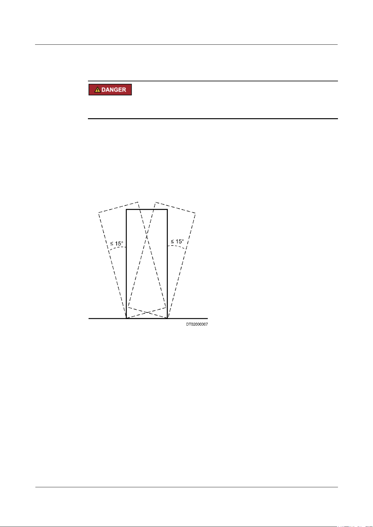
Moving Heavy Objects
Perform operations in accordance with all instructional symbols on the device.
Take caution to avoid injury when moving heavy objects.
When moving or lifting a device, hold the handle or bottom of the device.
When transporting a device using a pallet truck, the forks must be properly positioned to
ensure that the device does not topple. No excessive tilt or jolt is allowed during the
transportation, and the maximum tolerance of the tilting angle during loading and
unloading is 15°. To avoid toppling, secure the device to the pallet truck by using ropes
before moving, and assign persons to watch out the device during movement.
Move the cabinet with caution. Any bumping or falling may damage the device.
Figure 1-2 Tilting angle of a cabinet
Handling Fans
Do not insert fingers or boards into the operating fans until the fans are switched off, and have
stopped running.
1.6 Laying Out Cables
Binding Signal Cables

UPS5000-A-30 kVA & 40 kVA & 80 kVA
User Manual
1 Safety Precautions
Issue 11 (2018-12-10)
Copyright © Huawei Technologies Co., Ltd.
10
Signal cables must be bound separately from strong-current cables and high-voltage cables.
Laying Out Cables
When the temperature is low, a violent strike or vibrations may damage the cable sheathing.
To ensure cable safety, comply with the following requirements:
Cables can be laid, or installed, only when the temperature is higher than 0°C (32°F).
Handle cables with caution, especially at lower temperatures.
Before laying out cables that have been stored in temperatures lower than 0°C (32°F),
move the cables to an environment that is at the requisite ambient temperature. Store
them in this environment for at least 24 hours.
Do not drop the cables directly from the vehicle.
As the insulation layer of a cable may age, or be damaged from high temperatures,
ensure a sufficient distance between cables and the DC busbars, shunts, and fuses.
Cables prepared by the customer should be flame resistant. Cables must not be routed
behind the air exhaust vent of the cabinet. The air exhaust vent should not be blocked by
any object.
Before connecting a cable, ensure that the cable and cable label to be used meet the actual
installation requirements.
1.7 Information About Foreign Objects near UPS Equipment Installation
The purpose of this note is to provide information and warnings about the potential risks of
the operational integrity of an installed UPS. These risks are caused by foreign objects in or
near the UPS modules and relevant auxiliary equipment/components.
These risks are particularly high if conductive materials have entered the UPS modules/units
or the channels in the relevant auxiliary equipment/components.
Potential risks include damage to installed UPS equipment and subsequent power derating
and power failure of loads at critical positions.
Huawei UPS uses the highest safety standard in equipment design to ensure that live parts are
not in contact with the exterior and that no foreign object will enter the equipment during
operation.
However, when the UPS baffle plate and cover are open and the electrical wiring terminals
are exposed by the electrical contractor/installation personnel who are setting up a power line
connection, it is almost impossible to ensure that no foreign object will enter Huawei UPS
during onsite installation.
It is common to have someone working in the same room as the UPS during onsite
installation. Sometimes some people may be working above the UPS and relevant auxiliary
equipment/components.
To avoid serious damage to the onsite operation, property hazards, and personal injury
including fatal injury, it is the responsibility of each equipment manager or construction

UPS5000-A-30 kVA & 40 kVA & 80 kVA
User Manual
1 Safety Precautions
Issue 11 (2018-12-10)
Copyright © Huawei Technologies Co., Ltd.
11
manager to ensure that no foreign object enters the UPS modules/units or relevant auxiliary
equipment/components.
UPS5000-A-30 kVA & 40 kVA & 80 kVA
User Manual
2 Overview
Issue 11 (2018-12-10)
Copyright © Huawei Technologies Co., Ltd.
12
2.1 Model Description
This document describes the following UPS models:
UPS5000-A-30KTTL
UPS5000-A-40KTTL
UPS5000-A-80KTTL
2 Overview
Figure 2-1 Model number
2.2 Working Principles
indicates an input mode.
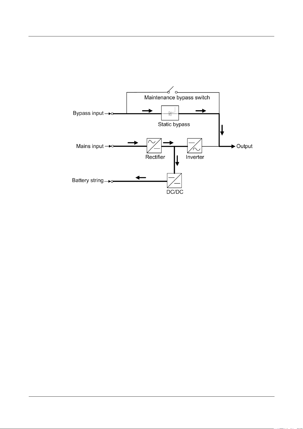
2.2.1 Conceptual Diagram
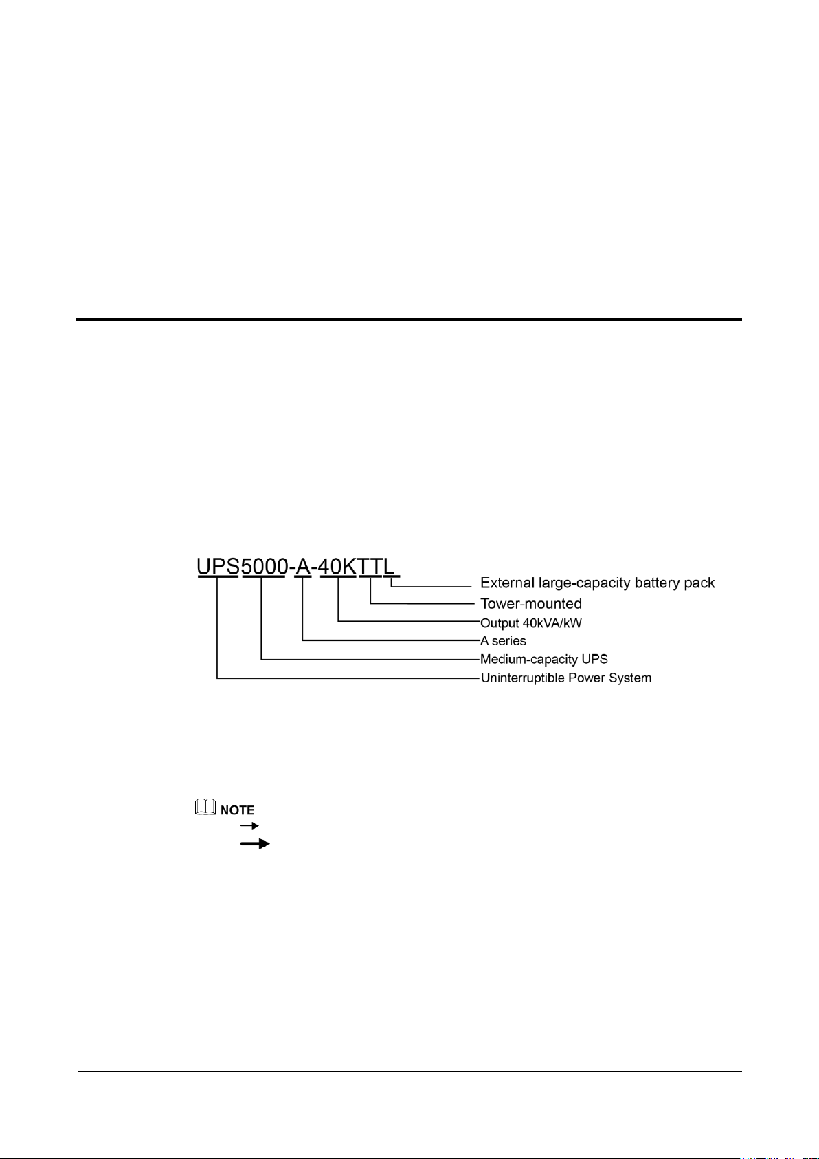
The UPS5000-A is an online double-conversion UPS that uses digital signal processing (DSP)
technology and features high efficiency and high power density. Figure 2-2 shows a
conceptual diagram for the UPS.
indicates the energy flow direction.
UPS5000-A-30 kVA & 40 kVA & 80 kVA
User Manual
2 Overview
Issue 11 (2018-12-10)
Copyright © Huawei Technologies Co., Ltd.
13
Figure 2-2 UPS conceptual diagram
2.2.2 Working Modes
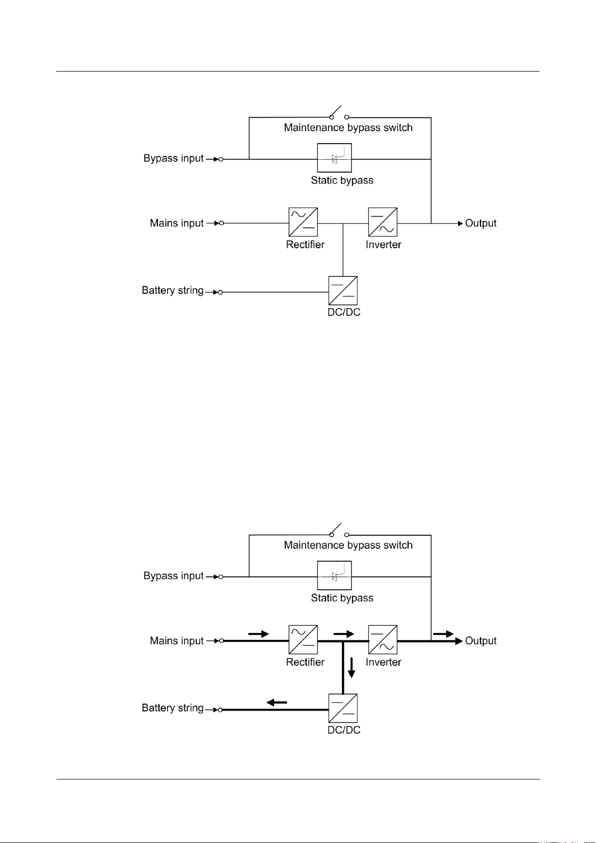
2.2.2.1 Normal Mode
When the UPS works in normal mode, the rectifier converts the AC input voltage into the DC
voltage, which is then raised to the bus voltage by the power factor correction (PFC) circuit.
Then one part of the voltage passes through the DC-DC circuit to charge the battery string,
and the other part is converted by the inverter into AC voltage outputs. The two conversions
ensure high-precision and high-quality output voltages, protecting loads from interferences
such as input harmonics, burrs, and voltage transients. Figure 2-3 shows the conceptual
diagram of the UPS working in normal mode.
Figure 2-3 UPS conceptual diagram in normal mode
UPS5000-A-30 kVA & 40 kVA & 80 kVA
User Manual
2 Overview
Issue 11 (2018-12-10)
Copyright © Huawei Technologies Co., Ltd.
14
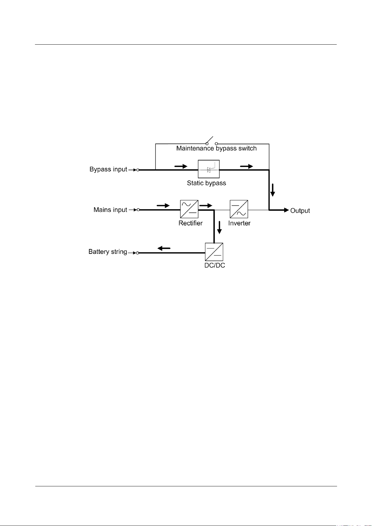
2.2.2.2 Bypass Mode
If the inverter does not start or is manually shut down after the UPS is powered on, the bypass
supplies power to loads. The UPS automatically transfers from normal mode to bypass mode
if it detects power unit overtemperature, overload, or other faults that may cause the inverter
to shut down. The bypass power supply is not protected by the UPS which means it may be
affected by mains outage, and incorrect AC voltage or frequency. Figure 2-4 shows a
conceptual diagram of the UPS working in bypass mode.
Figure 2-4 UPS conceptual diagram in bypass mode
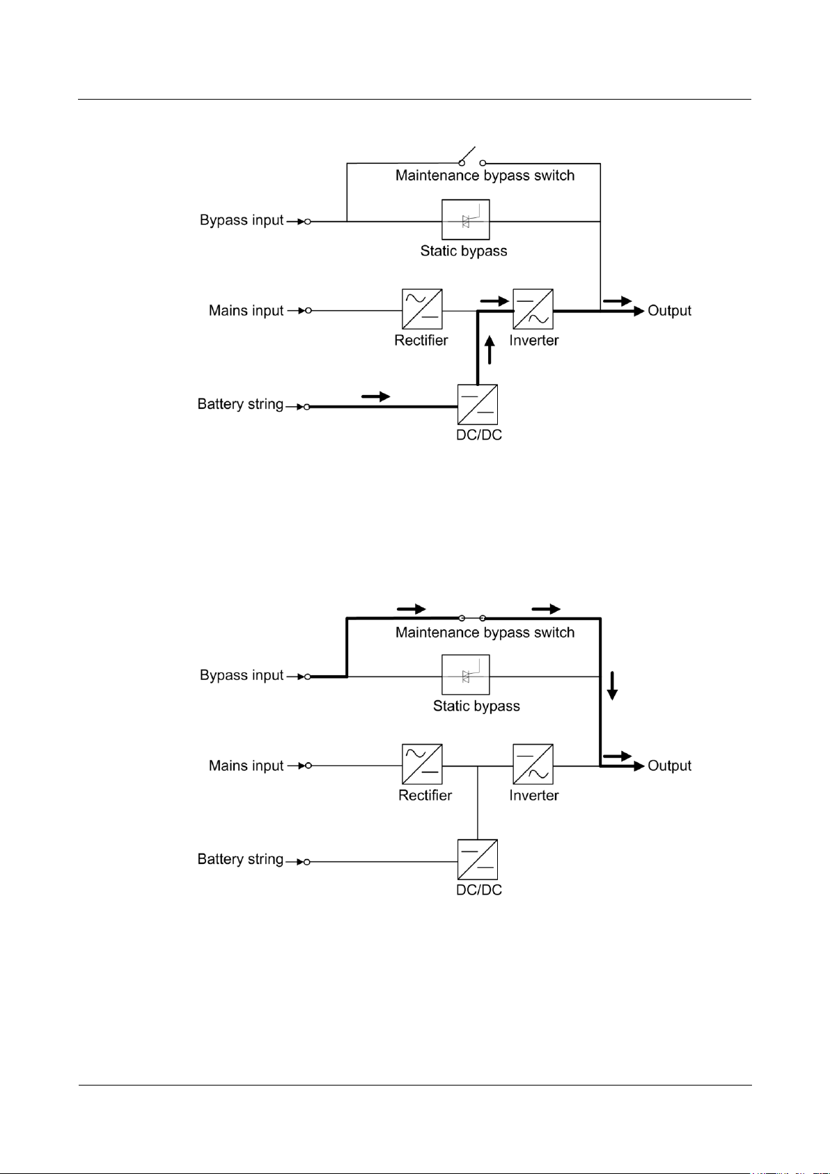
2.2.2.3 Battery Mode
If the AC input voltage is not normal, the UPS transfers to battery mode to obtain power from
batteries. The inverter then converts the power into AC outputs. Figure 2-5 shows a
conceptual diagram of the UPS working in battery mode.
UPS5000-A-30 kVA & 40 kVA & 80 kVA
User Manual
2 Overview
Issue 11 (2018-12-10)
Copyright © Huawei Technologies Co., Ltd.
15
Figure 2-5 UPS conceptual diagram in battery mode
2.2.2.4 Maintenance Bypass Mode
The current flows through the maintenance bypass, instead of the power unit or bypass unit.
UPS maintenance can be performed in this mode.
Figure 2-6 UPS conceptual diagram in maintenance bypass mode
2.2.2.5 ECO Mode
The economy control operation (ECO) mode is an energy-saving mode, which you can
configure on the liquid crystal display (LCD) or web user interface (WebUI). In ECO mode,
when the bypass input voltage is within the ECO voltage range, the bypass combined switch
turns on, and the bypass supplies power. When the bypass input voltage is beyond the ECO
UPS5000-A-30 kVA & 40 kVA & 80 kVA
User Manual
2 Overview
Issue 11 (2018-12-10)
Copyright © Huawei Technologies Co., Ltd.
16
voltage range, the UPS transfers from bypass mode to normal mode. In bypass mode or
normal mode, the rectifier keeps working and charges batteries using a charger. The ECO
mode delivers a higher efficiency. Figure 2-7 shows a conceptual diagram of the UPS working
in ECO mode.
Figure 2-7 UPS conceptual diagram in ECO mode
UPS5000-A-30 kVA & 40 kVA & 80 kVA
User Manual
2 Overview
Issue 11 (2018-12-10)
Copyright © Huawei Technologies Co., Ltd.
17
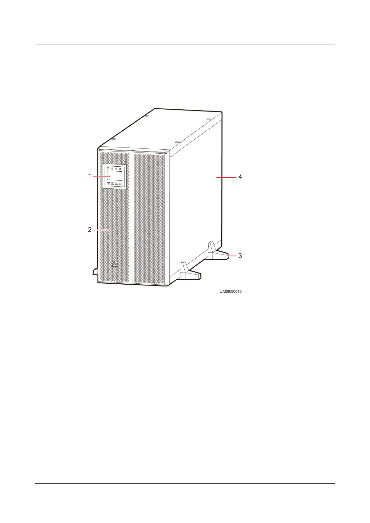
2.3 Product Description
(1) Monitor display unit (MDU)
(2) Front panel
(3) Support base
(4) Chassis
2.3.1 Appearance
Figure 2-8 UPS5000-A-30 kVA/40 kVA
UPS5000-A-30 kVA & 40 kVA & 80 kVA
User Manual
2 Overview
Issue 11 (2018-12-10)
Copyright © Huawei Technologies Co., Ltd.
18
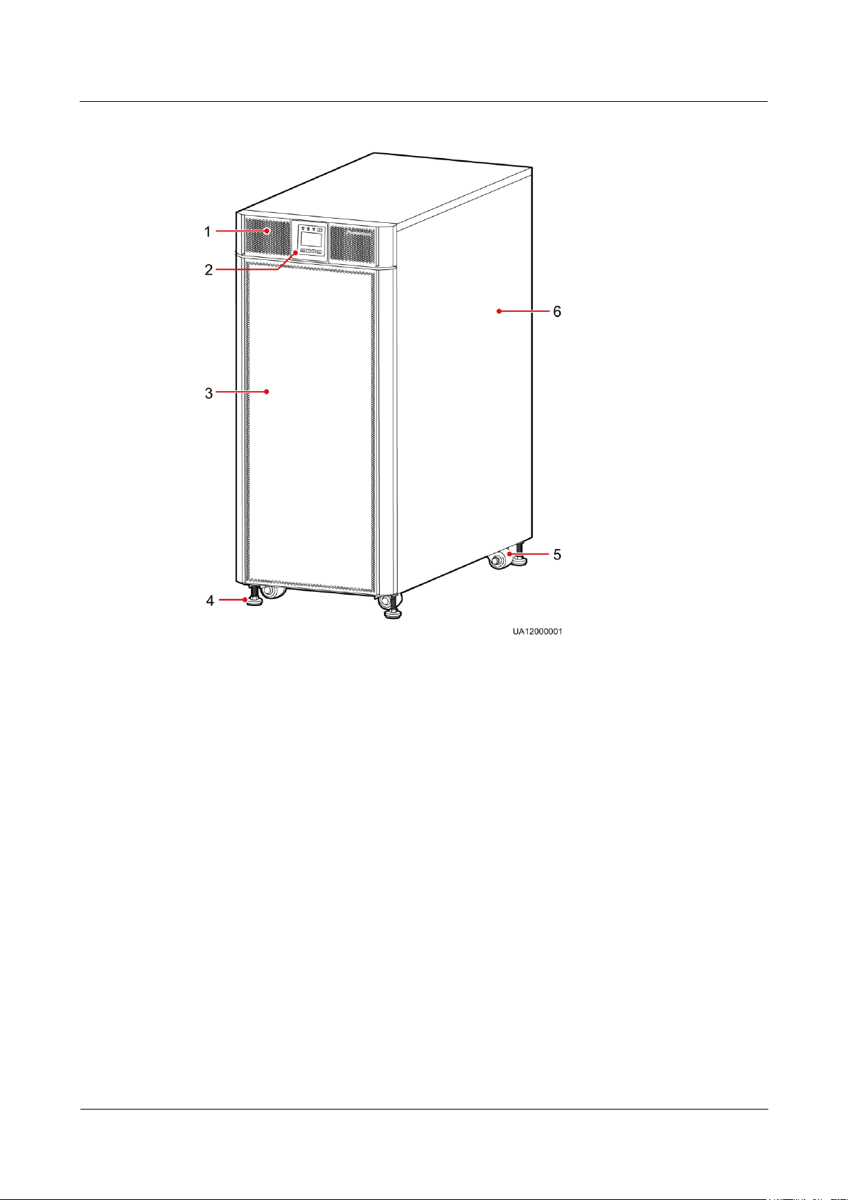
Figure 2-9 UPS5000-A-80 kVA
(1) Front panel 1
(2) MDU
(3) Front panel 2
(4) Leveling foot
(5) Castor
(6) Chassis
2.3.2 Product Structure
2.3.2.1 30 kVA/40 kVA UPS
Figure 2-10 and Figure 2-11 show the architecture of the UPS5000-A-30 kVA/40 kVA. Figure
2-10 shows the UPS with the front panel and the MDU removed.
UPS5000-A-30 kVA & 40 kVA & 80 kVA
User Manual
2 Overview
Issue 11 (2018-12-10)
Copyright © Huawei Technologies Co., Ltd.
19
Figure 2-10 UPS5000-A-30 kVA/40 kVA product structure (front view)
(1) Power unit
indicators
(2) Power unit ready
switch
(3) Bypass unit
indicators
(4) Bypass unit
ready switch
(5) MDU reset
button
(6) Dual in-line package
(DIP) switch
(7) MDU port
(8) Cold-start button
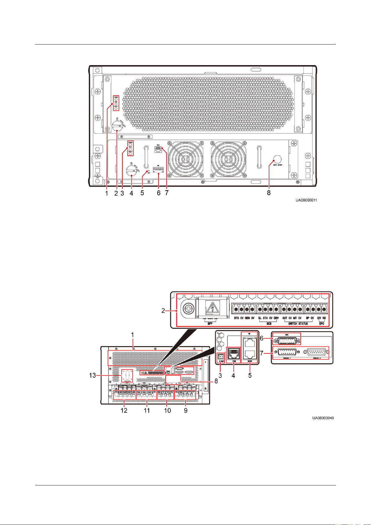
(1) Ventilation
panel on the rear
panel
(2) Dry contacts
(3) Battery
temperature sensor
port
(4) Ambient temperature
and humidity sensor port
or battery monitoring unit
(BMU) port
Figure 2-11 UPS5000-A-30 kVA/40 kVA product structure (rear view and enlarged view of
certain parts)

UPS5000-A-30 kVA & 40 kVA & 80 kVA
User Manual
2 Overview
Issue 11 (2018-12-10)
Copyright © Huawei Technologies Co., Ltd.
20
(5) FE port (upper)
and RS485 port
(lower)
(6) BSC port
(7) Parallel ports
(8) Slot for dry contact
card (optional)
(9) UPS mains
input terminals
(under the cover)
(10) UPS bypass
input terminals
(under the cover)
(11) Battery
wiring terminals
(under the cover)
(12) UPS output terminals
(under the cover)
(13) Maintenance
bypass switch
Indicators
DIP
Swit
ch
DIP1
DIP2
DIP3
LCD
Operation
Function
Remarks
Statu
s 1
OFF
OFF
OFF
N/A
Not
defined.
N/A
Connect the BMU by using a 04080298 transfer cable, which is delivered with the BMU.
When no ambient temperature and humidity sensor is installed, connect the BMU to the COM1 port
on the UPS.
When an ambient temperature and humidity sensor is installed, connect the BMU to the
RS485_OUT port on the sensor.
Both the power unit and bypass unit provide the Run indicator, Alarm indicator, and Fault
indicator (from top down).
MDU Reset Button
If the MDU does not work properly, use this button to reset the MDU, without affecting
power supply.
DIP Switch
Typically, three toggle switches are reserved for function settings. Table 2-1 describes the DIP
switch status.
Table 2-1 DIP switch status

UPS5000-A-30 kVA & 40 kVA & 80 kVA
User Manual
2 Overview
Issue 11 (2018-12-10)
Copyright © Huawei Technologies Co., Ltd.
21
DIP
Swit
ch
DIP1
DIP2
DIP3
LCD
Operation
Function
Remarks
Statu
s 2
ON
ON
OFF
Settings >
Restore
Default
Settings
Restores
factory
defaults.
After clearing system
parameters, battery
parameters, monitoring
parameters, and logs
(operation logs, upgrade
logs, and battery test
and statistics logs), the
MDU does not restart
automatically. The
settings will take effect
after the MDU is
powered on again.
Statu
s 3
ON
OFF
ON
Hold down
the Up and
Down
buttons at
the same
time for 5s.
Restores
the user
name and
password.
After restoring the
preset user name and
password, the MDU
restarts automatically,
without affecting power
supply.
Statu
s 4
ON
OFF
OFF
Control >
Clear
historical
alarms
Clears
historical
alarm
records.
After clearing historical
alarm records, the MDU
restarts automatically.
Statu
s 5
OFF
ON
ON
Control >
Clear
operation
logs
Clears
operation
logs.
After clearing operation
logs, the MDU restarts
automatically.
Statu
s 6
OFF
ON
OFF
Settings >
Advanced
Param. >
Work
mode >
Self-load
mode
Sets
self-load
mode.
After entering self-load
mode subsequent to
inverter startup, the
MDU does not restart
automatically.
Statu
s 7
OFF
OFF
ON
-
Not
defined.
-
Statu
s 8
ON
ON
ON
-
Not
defined.
-
 Loading...