

Huawei UPS2000-G-6KRTS, UPS2000-G-6KRTL, UPS2000-G-10KRTS, UPS2000-G-10KRTL, UPS2000-G-15KRTL User Manual
...Page 1
UPS2000-G-(6 kVA-20 kVA)
User Manual
Issue
10
Date
2017-01-19
HUAWEI TECHNOLOGIES CO., LTD.
Page 2

Issue 10 (2017-01-19)
Huawei Proprietary and Confidential
Copyright © Huawei Technologies Co., Ltd.
i
Copyright © Huawei Technologies Co., Ltd. 2017. All rights reserved.
No part of this document may be reproduced or transmitted in any form or by any means without prior
written consent of Huawei Technologies Co., Ltd.
Trademarks and Permissions
and other Huawei trademarks are trademarks of Huawei Technologies Co., Ltd.
All other trademarks and trade names mentioned in this document are the property of their respective
holders.
Notice
The purchased products, services and features are stipulated by the contract made between Huawei and
the customer. All or part of the products, services and features described in this document may not be
within the purchase scope or the usage scope. Unless otherwise specified in the contract, all statements,
information, and recommendations in this document are provided "AS IS" without warranties, guarantees or
representations of any kind, either express or implied.
The information in this document is subject to change without notice. Every effort has been made in the
preparation of this document to ensure accuracy of the contents, but all statements, information, and
recommendations in this document do not constitute a warranty of any kind, express or implied.
Huawei Technologies Co., Ltd.
Address:
Huawei Industrial Base
Bantian, Longgang
Shenzhen 518129
People's Republic of China
Website:
http://e.huawei.com
Page 3
UPS2000-G-(6 kVA-20 kVA)
User Manual
About This Document
Issue 10 (2017-01-19)
Huawei Proprietary and Confidential
Copyright © Huawei Technologies Co., Ltd.
ii
About This Document
Purpose
This document describes the UPS2000-G-(6 kVA–20 kVA) in terms of features, performance,
appearance, structure, working principle, installation, operation, and maintenance. UPS is
short for uninterruptible power system.
Intended Audience
This document is intended for:
Sales Engineer
Technical Support Engineer
System Engineer
Hardware Installation Engineer
Commissioning Engineer
Data Configuration Engineer
Maintenance Engineer
Symbol Conventions
The symbols that may be found in this document are defined as follows.
Symbol
Description
Indicates an imminently hazardous situation which, if
not avoided, will result in death or serious injury.
Indicates a potentially hazardous situation which, if not
avoided, could result in death or serious injury.
Indicates a potentially hazardous situation which, if not
avoided, may result in minor or moderate injury.
Indicates a potentially hazardous situation which, if not
avoided, could result in equipment damage, data loss,
performance deterioration, or unanticipated results.
Page 4
UPS2000-G-(6 kVA-20 kVA)
User Manual
About This Document
Issue 10 (2017-01-19)
Huawei Proprietary and Confidential
Copyright © Huawei Technologies Co., Ltd.
iii
Symbol
Description
NOTICE is used to address practices not related to
personal injury.
Calls attention to important information, best practices
and tips.
NOTE is used to address information not related to
personal injury, equipment damage, and environment
deterioration.
Change History
Changes between document issues are cumulative. The latest document issue contains all the
changes made in earlier issues.
Issue 10 (2017-01-19)
Added the DHCP feature.
Added an external dry contact card.
The default value of Max. current parameter changed to 2.0 A.
Issue 09 (2016-10-10)
The software is upgraded.
Issue 08 (2016-01-06)
The software is upgraded.
Issue 07 (2015-03-30)
The alarm handling is upgraded.
Issue 06 (2014-10-09)
Added the shutdown delay parameter.
Issue 05 (2014-07-31)
Upgraded the Optional Components.
Issue 04 (2013-11-06)
Added the description of Checking Before Powering On the UPS
Issue 03 (2013-08-24)
Added the description of the UPS2000-G-15 kVA/20 kVA three-phase input single-phase
output and single-phase input single-phase output.
Page 5

UPS2000-G-(6 kVA-20 kVA)
User Manual
About This Document
Issue 10 (2017-01-19)
Huawei Proprietary and Confidential
Copyright © Huawei Technologies Co., Ltd.
iv
Issue 02 (2013-06-10)
The software is upgraded.
Issue 01 (2013-05-15)
This is the first release.
Page 6

UPS2000-G-(6 kVA-20 kVA)
User Manual
Contents
Issue 10 (2017-01-19)
Huawei Proprietary and Confidential
Copyright © Huawei Technologies Co., Ltd.
v
Contents
About This Document .................................................................................................................... ii
1 Safety Precautions ......................................................................................................................... 1
1.1 General Safety .............................................................................................................................................................. 1
1.2 Electrical Safety ................................ ................................................................ ............................................................ 3
1.3 Operating Environment................................................................................................................................................. 6
1.4 Battery .......................................................................................................................................................................... 7
1.5 Mechanical Safety ........................................................................................................................................................ 9
1.6 Laying Out Cables ...................................................................................................................................................... 11
2 UPS2000-G-(6kVA-20kVA) Quick Introduction ................................................................... 12
2.1 Model Description ...................................................................................................................................................... 12
2.2 Working Principle ....................................................................................................................................................... 13
2.2.1 Conceptual Diagram ................................................................................................................................................ 13
2.2.2 Working Modes ........................................................................................................................................................ 13
2.3 Appearance ................................................................................................................................................................. 14
2.4 Optional Components ................................................................................................................................................. 18
3 Installation.................................................................................................................................... 25
3.1 Preparations ................................................................................................................................................................ 25
3.1.1 Site ........................................................................................................................................................................... 25
3.1.2 Tools ........................................................................................................................................................................ 27
3.1.3 Power Cables ........................................................................................................................................................... 28
3.1.4 Unpacking and Checking ......................................................................................................................................... 33
3.2 Single UPS/Parallel System Installation ..................................................................................................................... 34
3.3 Installing a Backfeed Protection Device ..................................................................................................................... 34
3.3.1 Feedback Prevention Connections (With Dry Contract Control) ............................................................................. 36
3.4 Check After Installation .............................................................................................................................................. 39
4 Control Panel ............................................................................................................................... 41
4.1 Introduction ................................................................................................................................................................ 41
4.2 Indicators .................................................................................................................................................................... 41
4.3 Functional Buttons ...................................................................................................................................................... 42
4.4 LCD ................................................................................................................................ ............................................ 43
4.5 LCD Startup Screens .................................................................................................................................................. 43
Page 7

UPS2000-G-(6 kVA-20 kVA)
User Manual
Contents
Issue 10 (2017-01-19)
Huawei Proprietary and Confidential
Copyright © Huawei Technologies Co., Ltd.
vi
4.5.1 Starting the UPS in Normal Mode ........................................................................................................................... 45
4.5.2 Starting the UPS in Battery Mode ........................................................................................................................... 46
4.6 LCD Menu Hierarchy ................................................................................................ ................................................. 47
4.6.1 Status Screen ............................................................................................................................................................ 49
4.6.2 Alarms Screen .......................................................................................................................................................... 53
4.6.3 Settings Screen......................................................................................................................................................... 55
4.6.4 Control Screen ......................................................................................................................................................... 68
4.6.5 About Screen ............................................................................................................................................................ 71
5 Operations .................................................................................................................................... 73
5.1 Checking Before Powering On the UPS ..................................................................................................................... 73
5.2 Single UPS Operations ............................................................................................................................................... 73
5.2.1 Starting the UPS....................................................................................................................................................... 73
5.2.2 Shutting down the UPS ............................................................................................................................................ 76
5.2.3 Performing EPO ....................................................................................................................................................... 77
5.3 Parallel System Operations ......................................................................................................................................... 77
5.3.1 Starting the Parallel System ..................................................................................................................................... 78
5.3.2 Shutting down the Parallel System .......................................................................................................................... 81
5.3.3 Performing EPO ....................................................................................................................................................... 82
6 Communications ......................................................................................................................... 83
6.1 Optional Communications Components ..................................................................................................................... 83
6.2 SNMP Card ................................................................................................................................................................. 83
6.3 Modbus Card .............................................................................................................................................................. 84
6.4 Dry Contact Card ........................................................................................................................................................ 84
6.5 External Dry Contact Card ......................................................................................................................................... 84
7 Routine Maintenance ................................................................................................................. 85
7.1 UPS Maintenance ....................................................................................................................................................... 85
7.2 Battery Maintenance ................................................................................................................................................... 86
8 Troubleshooting .......................................................................................................................... 91
9 Technical Specifications ............................................................................................................ 93
9.1 Physical Specifications ............................................................................................................................................... 93
9.2 Environmental Specifications ..................................................................................................................................... 93
9.3 Mains Input Electrical Specifications ......................................................................................................................... 94
9.4 Bypass Input Electrical Specifications ........................................................................................................................ 95
9.5 Output Electrical Specifications ................................................................................................................................. 95
9.6 Battery Specifications ................................................................................................................................................. 96
9.7 ECO Feature ............................................................................................................................................................. 104
9.8 Parallel Feature ......................................................................................................................................................... 104
9.9 Safety Regulations and EMC .................................................................................................................................... 104
A Parallel Parameter List ............................................................................................................ 105
Page 8

UPS2000-G-(6 kVA-20 kVA)
User Manual
Contents
Issue 10 (2017-01-19)
Huawei Proprietary and Confidential
Copyright © Huawei Technologies Co., Ltd.
vii
B LCD Menus and Parameters................................................................................................... 106
C Alarm Handling ........................................................................................................................ 118
D Alarm Handing of Battery Maintenance Notification ...................................................... 141
E Battery Shallow Discharge Test ............................................................................................. 143
F Capacity Test .............................................................................................................................. 146
G Acronyms and Abbreviations................................................................................................ 149
Page 9
UPS2000-G-(6 kVA-20 kVA)
User Manual
1 Safety Precautions
Issue 10 (2017-01-19)
Huawei Proprietary and Confidential
Copyright © Huawei Technologies Co., Ltd.
1
1 Safety Precautions
1.1 General Safety
This section describes safety precautions to consider before installing, maintaining, and
operating the UPS.
To minimize the risk of personal injury and damage to equipment, read and follow all the
precautions in this document before performing any operation. The "DANGER",
"WARNING", "CAUTION", and "NOTICE" statements in this document are only
supplemental and do not represent all the safety instructions.
Only trained and qualified personnel are allowed to install, operate, and maintain Huawei
equipment.
Follow the precautions and special safety instructions provided by Huawei when operating
Huawei products. Huawei will not be liable for any consequences that are caused due to
violations regarding general safety regulations and equipment design, production, and usage
safety standards.
Declaration
Huawei does not take responsibilities for the following situations:
Operation under severe environments that are not specified in this document.
Installation or use in environments that are not specified in related international
standards.
Unauthorized product changes and software code modification.
Operations not complying with the operation instructions and safety precautions in this
document.
Damage caused by extreme natural environments.
Damage caused by using batteries provided by Huawei for non-Huawei UPSs.
Damage caused by using batteries not provided by Huawei.
Page 10
UPS2000-G-(6 kVA-20 kVA)
User Manual
1 Safety Precautions
Issue 10 (2017-01-19)
Huawei Proprietary and Confidential
Copyright © Huawei Technologies Co., Ltd.
2
Power Grid Requirements
A standard UPS can connect to a three-phase, five-wire (L1, L2, L3, N, PE) TT, TN-C, TN-S,
and TN-C-S AC power distribution system (IEC60364-1).
Local Laws and Regulations
Equipment operations must comply with local laws and regulations. The safety instructions in
this document are only supplemental to local safety regulations.
Personal Requirements
Only engineers certified by the manufacturer or its agents are allowed to perform UPS
commissioning and maintenance. Otherwise, human injury or equipment damage may occur,
and any resulting UPS faults will be beyond warranty scope.
Personnel who plan to install or maintain Huawei equipment must receive thorough training,
understand all necessary safety precautions, and master the correct operation methods.
Trained and qualified personnel, or personnel certified or authorized by Huawei are:
Allowed to install, operate, and maintain the equipment.
Allowed to remove safety facilities and inspect the equipment.
Allowed to replace or change the devices or components (including software).
Operation personnel must report faults or errors that might cause serious safety issues to
related owners.
This product should be installed and used according to the installation and technical,
specification requirements found in this manual. Otherwise, the product may be damaged,
and the resulting product exceptions or component damage will be beyond the warranty
scope.
Grounding Requirements
Devices to be grounded (excluding the energy storage unit) must meet the following
requirements:
When installing a device, install the ground cable first. When removing a device, remove
the ground cable at the very end.
Do not damage the ground conductor.
Do not operate devices if the ground conductor is not installed. Before operating a device,
check the electrical connection of the device to ensure that it is securely grounded.
Personal Safety
Do not operate the product, or handle cables, during thunderstorms.
To avoid electric shocks, do not connect safety extra-low voltage (SELV) circuits to
telecommunication network voltage (TNV) circuits.
Page 11

UPS2000-G-(6 kVA-20 kVA)
User Manual
1 Safety Precautions
Issue 10 (2017-01-19)
Huawei Proprietary and Confidential
Copyright © Huawei Technologies Co., Ltd.
3
Before operating a device, wear electrostatic discharge (ESD) clothes, ESD gloves, and
an ESD wrist strap. Remove any conductors (such as jewelry or watches) before the
operation to avoid electric shocks or burns.
In the case of fire, leave the building or the equipment room immediately, and turn on the
fire alarm bell or make an emergency call. Never enter the building on fire in any case.
If the cabinet provides an ESD jack, wear an ESD wrist strap and insert the ground
terminal of the ESD wrist strap into the jack.
Ensure all switches are turned to OFF during device installation.
Power on the UPS only after authorized engineers arrive at the site.
If a C2 UPS is used in residential areas, additional measures must be taken to prevent
radio frequency interferences.
If the UPS is used for life-supporting medical apparatus and facilities such as lifts where
adequate care has to be taken to ensure personal safety, discuss with the manufacturer in
advance about the applicability, settings, management, and maintenance of the UPS,
which require special considerations during design.
Device Safety
Before operation, ensure that the device is firmly anchored to the floor or other solid
objects, such as a wall or an installation rack.
Ensure ventilation vents are unblocked while the system is operating.
Before powering on the device, ensure that all the screws inside it are securely tightened
and will not fall off during operation.
After the installation, remove packing materials from the equipment area.
Replace warning labels that have worn out or are unreadable.
A UPS can be used to serve resistive-capacitive loads, resistive loads, and
micro-inductive loads. It is recommended that a UPS not be used for pure capacitive
loads, pure inductive loads, and half-wave rectification loads. It does not apply to energy
feedback loads.
Do not alter the UPS internal structure or installation procedure unless consent from the
manufacturer is given.
Never use water to clean electrical components inside or outside the UPS.
Do not drill holes into a cabinet.
1.2 Electrical Safety
High Voltage
Page 12
UPS2000-G-(6 kVA-20 kVA)
User Manual
1 Safety Precautions
Issue 10 (2017-01-19)
Huawei Proprietary and Confidential
Copyright © Huawei Technologies Co., Ltd.
4
The high voltage power supply provides power for the device operation. Direct or indirect
contact with high voltage power sources may result in fatal injury.
Non-standard or incorrect high voltage operations may result in fire and electric shocks.
The personnel who install the AC facility must be qualified to perform high voltage and
AC operations.
When selecting, connecting, and routing power cables, ensure compliance with local
laws and regulations.
When installing the AC power supply facility, ensure compliance with local laws and
regulations.
Before connecting cables to the UPS, ensure that the input power and mains power
distribution switches and output power distribution switch are turned off.
Use only dedicated tools during high voltage and AC operations.
If the operation is performed in a damp environment, ensure that the device is dry. When
water is found in the rack or the rack is damp, switch off the power supply immediately.
High Leakage Current
Ground a device before powering it on. Otherwise, personal injury or device damage may
occur.
If a "high leakage current" tag is attached to the panel of the device, ground the protective
ground terminal on the device enclosure before connecting the AC power supply to
prevent electric shocks.
The UPS can generate high leakage currents. Using a circuit breaker that has the leakage
current protection function is not recommended.
Power Cable
Do not install or remove power cables when the device is on. Transient contact between the
core of the power cable and the conductor may generate electric arcs or sparks, which may
cause fire or damage eyesight.
Before moving or reconnecting the UPS, disconnect the mains and batteries, open the
output power distribution switch, and wait a period of at least 5 minutes after the UPS
completely powers off. Otherwise, electric shocks may occur.
Before installing or removing the power cable, open the power switch.
Before connecting a power cable, check that its label is correct.
Page 13
UPS2000-G-(6 kVA-20 kVA)
User Manual
1 Safety Precautions
Issue 10 (2017-01-19)
Huawei Proprietary and Confidential
Copyright © Huawei Technologies Co., Ltd.
5
Fuse
If a fuse needs replacing, ensure the new fuse is of the same type and specifications so that the
system runs safely.
Backfeed Protection Dry Contact
The UPS can be configured with a backfeed protection dry contact to work with an external
automatic circuit breaker, preventing the voltage from flowing back to input terminals over
static bypass circuits. If device installation and maintenance personnel do not need to use
backfeed protection, paste labels on the external bypass input circuit breakers informing that
the circuit is connected to the UPS. Disconnect the device from the UPS before performing
operations on the circuit.
Electrostatic Discharge
Static electricity generated by human bodies may damage the electrostatic-sensitive
components on boards, for example, the large-scale integrated (LSI) circuits.
To prevent damage to electrostatic-sensitive components, wear a pair of ESD gloves or a
well-grounded ESD wrist strap when touching the device or handling boards or
application-specific integrated circuits (ASICs).
When holding a board, hold its edge without touching any components, especially chips.
Package boards with ESD packaging materials before storing or transporting them.
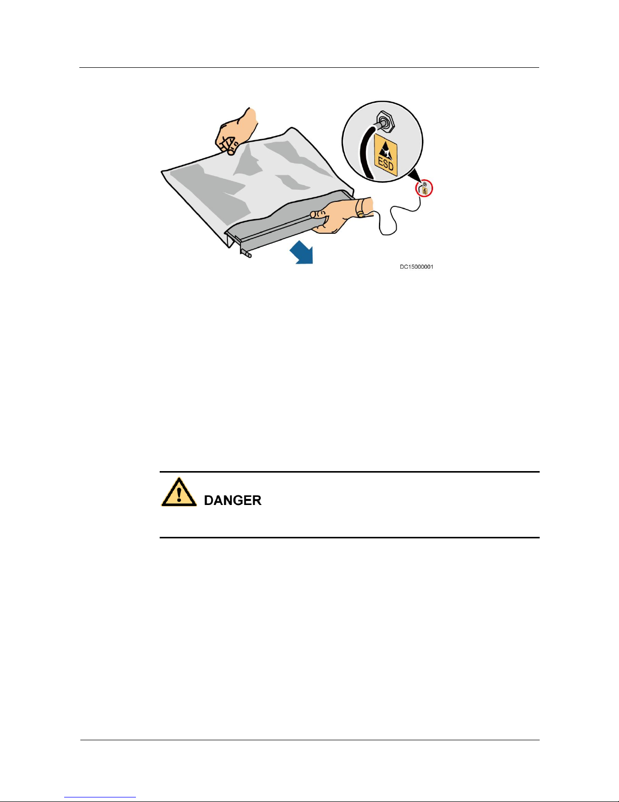
Figure 1-1 shows how to wear an ESD wrist strap.
Page 14
UPS2000-G-(6 kVA-20 kVA)
User Manual
1 Safety Precautions
Issue 10 (2017-01-19)
Huawei Proprietary and Confidential
Copyright © Huawei Technologies Co., Ltd.
6
Figure 1-1 Wearing an ESD wrist strap
Liquid Prevention
Do not place the product under areas prone to water leakage, such as near air conditioner
vents, ventilation vents, or feeder windows of the equipment room. Ensure that there is
no condensation inside the product or equipment room. Ensure that no liquid enters the
product. Otherwise, short circuits will occur and may result in serious injury or death.
If any liquid is detected inside the product, immediately disconnect the power supply and
contact the administrator.
1.3 Operating Environment
Do not expose the equipment or perform any operations in an environment with flammable or
explosive gas, or smoke.
Any operation on any electrical device in an environment that has flammable air can cause
extreme danger. Strictly obey the operating environmental requirements specified in related
use manuals when using or storing the device.
Do not places the UPS in the following environments:
Places where the temperature and humidity are beyond the range of 0–40°C and
0%–95% RH respectively.
Places in direct sunlight or near heat sources.
Places subject to vibrations or shocks.
Dusty places, or places exposed to corrosive substances or salts.
Marine environments or outdoor land environments (with simple shielding measures)
near pollution sources. If a site is near a pollution source, it must be at most:
− 3.7 km away from saline water areas such as the ocean.
Page 15
UPS2000-G-(6 kVA-20 kVA)
User Manual
1 Safety Precautions
Issue 10 (2017-01-19)
Huawei Proprietary and Confidential
Copyright © Huawei Technologies Co., Ltd.
7
− 3 km away from serious pollution sources, such as metallurgic plants, coal mines,
and thermal power plants.
− 2 km away from secondary pollution sources, such as chemical, rubber, and
galvanization industries.
− 1 km away from light pollution sources, such as packing houses, tanneries, and
boiler rooms.
1.4 Battery
This section describes precautions for operating batteries.
Before operating batteries, carefully read the safety precautions for battery handling and
connection.
To ensure battery security and efficient battery management, use the batteries delivered
with the UPS. Huawei shall not be responsible for battery damage caused by using
non-Huawei batteries for Huawei UPSs.
Handle lead-acid batteries according to local regulations.
Incorrect handling of batteries causes hazards. When operating batteries, avoid battery
short circuits and electrolyte overflow or leakage.
Electrolyte overflow may damage the device. It will corrode metal parts and circuit
boards, and ultimately damage the device and cause short circuits of circuit boards.
Short circuits caused by incorrect operations may cause serious injuries due to high
power of batteries.
Do not reversely connect positive and negative battery terminals.
Use batteries of the specified type. Otherwise, the batteries may be damaged.
Check battery connections periodically to ensure that all screws are securely tightened.
Install or store batteries in clean, cool, and dry environments.
Do not decompose, transform, or damage batteries. Otherwise, battery short circuits, acid
leaks, and even human injuries may result.
Page 16
UPS2000-G-(6 kVA-20 kVA)
User Manual
1 Safety Precautions
Issue 10 (2017-01-19)
Huawei Proprietary and Confidential
Copyright © Huawei Technologies Co., Ltd.
8
Technical Specifications
Table 1-1 Battery specifications
Battery Type
Minimum/Ma
ximum
Number of
Batteries
Cell Float
Voltage
Cell
Equalized
Voltage
Cell
Minimum
Voltage
Sealing
lead-acid
battery
Sixteen to
twenty 12 V
batteries
2.23–2.27
V/cell
2.3–2.4 V/cell
1.6–1.9 V/cell
Open lead-acid
battery
Sixteen to
twenty 12 V
batteries
2.23–2.27
V/cell
2.3–2.4 V/cell
1.6–1.9 V/cell
A cell indicates a 2 V cell, each 12 V battery consists of six cells.
Preventative Measures
When installing and maintaining batteries, pay attention to the following points:
Use special insulation tools.
Take care to protect your eyes when operating batteries.
Wear rubber gloves and a protective coat in case of electrolyte overflow.
When moving a battery, ensure that its electrodes are upward. Leaning or reversing the
battery is prohibited.
Switch off the power supply during installation and maintenance.
Short Circuit
Battery short circuits may cause human injuries. Although the voltage of ordinary batteries is
low, the instantaneous high current caused by the short circuit releases a great deal of energy.
To avoid battery short circuits, do not maintain batteries in use.
Harmful Gas
Page 17
UPS2000-G-(6 kVA-20 kVA)
User Manual
1 Safety Precautions
Issue 10 (2017-01-19)
Huawei Proprietary and Confidential
Copyright © Huawei Technologies Co., Ltd.
9
Do not use unsealed lead-acid batteries. Place and secure lead-acid batteries horizontally to
avoid inflammation or device corrosion due to flammable gases emitted from batteries.
The lead-acid batteries in use may emit flammable gases. Therefore, store the batteries in a
place with good ventilation, and take precautions against fire.
Battery Temperature
High temperature may result in battery distortion, damage, and electrolyte overflow.
Install or store batteries far away from fire and heating sources, such as transformers.
Never burn batteries.
When the temperature of the battery is higher than 60°C, check the battery for electrolyte
overflow. If the electrolyte overflows, absorb and counteract the electrolyte immediately.
Acid Leakage
In the case of electrolyte leaks, counteract and absorb the leaking electrolyte immediately.
When moving or handling a battery whose electrolyte leaks, note that the leaking electrolyte
may hurt human bodies. When you find the electrolyte leaks, use the following substances to
counteract and absorb the leaking electrolyte:
Sodium bicarbonate (baking soda): NaHCO3
Sodium carbonate (soda): Na2CO3
When using substances to counteract and absorb electrolytes, strictly follow the guidelines
provided by the battery supplier.
If your body meets the acid, wash the part that has met the acid with clean water immediately,
or immediately call a doctor if the situation is serious.
1.5 Mechanical Safety
Moving Sharp Objects
Page 18
UPS2000-G-(6 kVA-20 kVA)
User Manual
1 Safety Precautions
Issue 10 (2017-01-19)
Huawei Proprietary and Confidential
Copyright © Huawei Technologies Co., Ltd.
10
Wear protective gloves when moving sharp objects.
Moving Heavy Objects
Perform operations in accordance with all instructional symbols on the device.
Take caution to avoid injury when moving heavy objects.
When moving or lifting a device, hold the handle or bottom of the device.
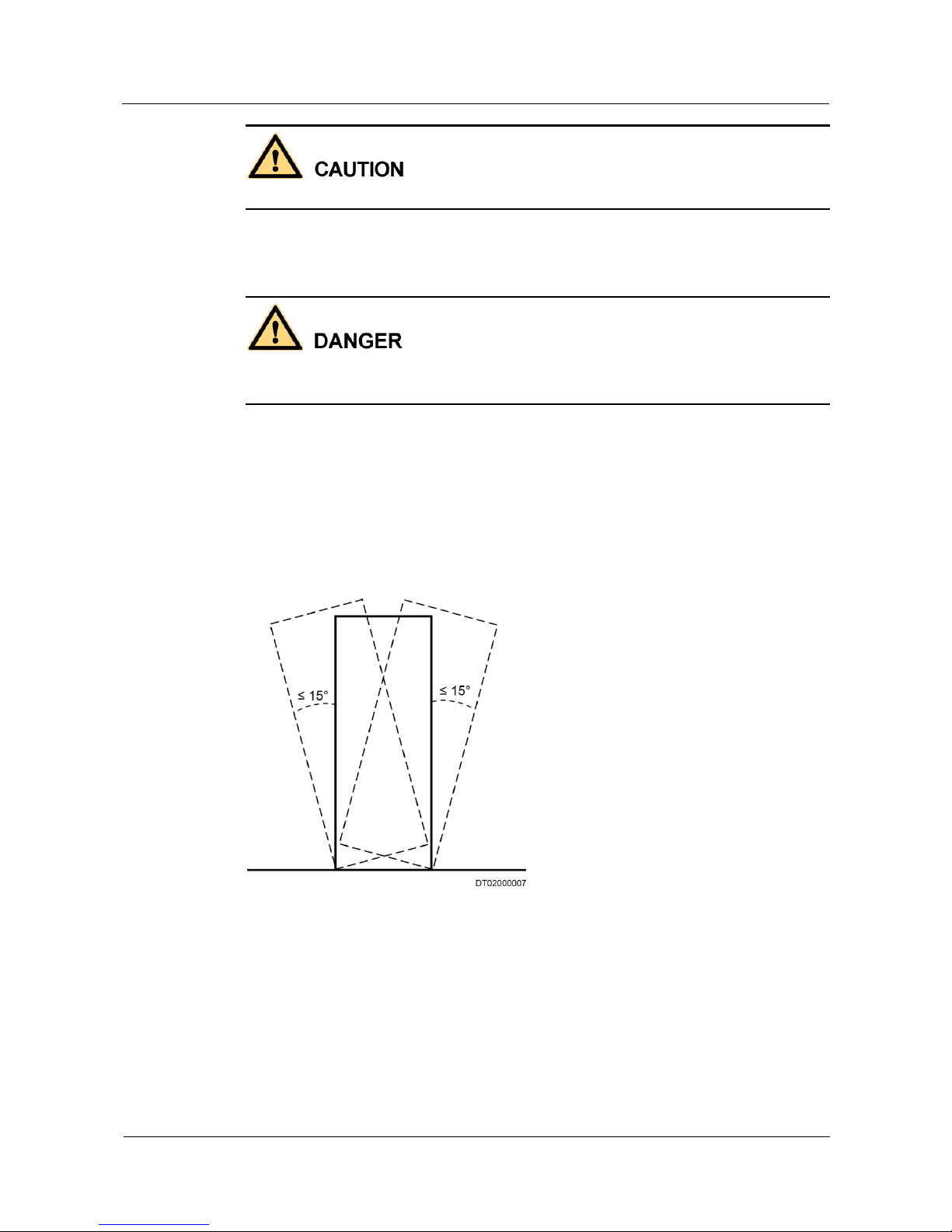
When transporting a device using a pallet truck, the forks must be properly positioned to
ensure that the device does not topple. No excessive tilt or jolt is allowed during the
transportation, and the maximum tolerance of the tilting angle during loading and
unloading is 15°. To avoid toppling, secure the device to the pallet truck by using ropes
before moving, and assign persons to watch out the device during movement.
Move the cabinet with caution. Any bumping or falling may damage the device.
Figure 1-2 Tilting angle of a cabinet
Handling Fans
Do not insert fingers or boards into the operating fans until the fans are switched off, and have
stopped running.
Page 19
UPS2000-G-(6 kVA-20 kVA)
User Manual
1 Safety Precautions
Issue 10 (2017-01-19)
Huawei Proprietary and Confidential
Copyright © Huawei Technologies Co., Ltd.
11
1.6 Laying Out Cables
Binding Signal Cables
Signal cables must be bound separately from strong-current cables and high-voltage cables.
Laying Out Cables
When the temperature is low, a violent strike or vibrations may damage the cable sheathing.
To ensure cable safety, comply with the following requirements:
Cables can be laid, or installed, only when the temperature is higher than 0°C (32°F).
Handle cables with caution, especially at lower temperatures.
Before laying out cables that have been stored in temperatures lower than 0°C (32°F),
move the cables to an environment that is at the requisite ambient temperature. Store
them in this environment for at least 24 hours.
Do not drop the cables directly from the vehicle.
As the insulation layer of a cable may age, or be damaged from high temperatures,
ensure a sufficient distance between cables and the DC busbars, shunts, and fuses.
Cables prepared by the customer should be flame resistant. Cables must not be routed
behind the air exhaust vent of the cabinet. The air exhaust vent should not be blocked by
any object.
Before connecting a cable, ensure that the cable and cable label to be used meet the actual
installation requirements.
Page 20
UPS2000-G-(6 kVA-20 kVA)
User Manual
2 UPS2000-G-(6kVA-20kVA) Quick Introduction
Issue 10 (2017-01-19)
Huawei Proprietary and Confidential
Copyright © Huawei Technologies Co., Ltd.
12
2 UPS2000-G-(6kVA-20kVA) Quick
Introduction
2.1 Model Description
This document describes the following UPS models:
Model
Represented By
Remarks
UPS2000-G-6KRTS
UPS2000-G-6 kVA
standard model
The two models are represented by
UPS2000-G-6 kVA in the description
of their common features and
parameters.
UPS2000-G-6KRTL
UPS2000-G-6 kVA
long backup time model
UPS2000-G-10KRTS
UPS2000-G-10 kVA
standard model
The two models are represented by
UPS2000-G-10 kVA in the
description of their common features
and parameters.
UPS2000-G-10KRTL
UPS2000-G-10 kVA
long backup time model
UPS2000-G-15KRTL
UPS2000-G-15 kVA
The UPS2000-G-15KRTL has only a
long backup time model.
UPS2000-G-20KRTL
UPS2000-G-20 kVA
The UPS2000-G-20KRTL has only a
long backup time model.
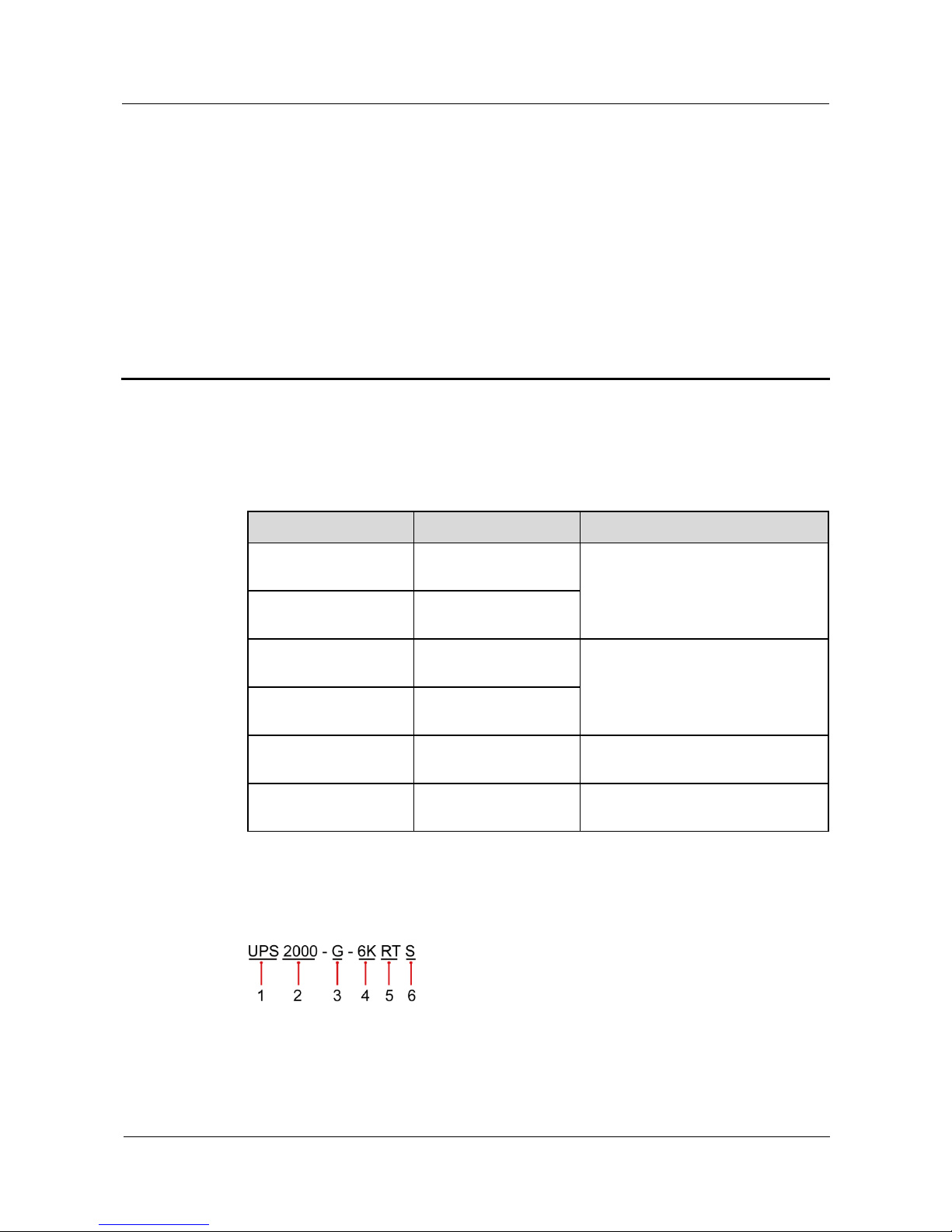
Figure 2-1 shows a UPS model number.
Figure 2-1 Model number
Table 2-1 describes the model number.
Page 21
UPS2000-G-(6 kVA-20 kVA)
User Manual
2 UPS2000-G-(6kVA-20kVA) Quick Introduction
Issue 10 (2017-01-19)
Huawei Proprietary and Confidential
Copyright © Huawei Technologies Co., Ltd.
13
Table 2-1 Model number details
No.
Item
Description
1
Product category
UPS
2
Product family
2000: Power ≤ 20 kVA
3
UPS subcategory
G: series name
4
Output capacity
6K: 6 kVA
10K: 10 kVA
15K: 15 kVA
20K: 20 kVA
5
UPS type
RT: rack- and tower-mounted unit
RR: rack-mounted unit
TT: tower-mounted unit
TM: modular tower-mounted unit
RM: modular rack-mounted unit
6
Built-in battery
(optional)
S: standard model, which provides only a standard
battery pack.
L: long backup time model. You need to use an external
large-capacity battery pack.
2.2 Working Principle
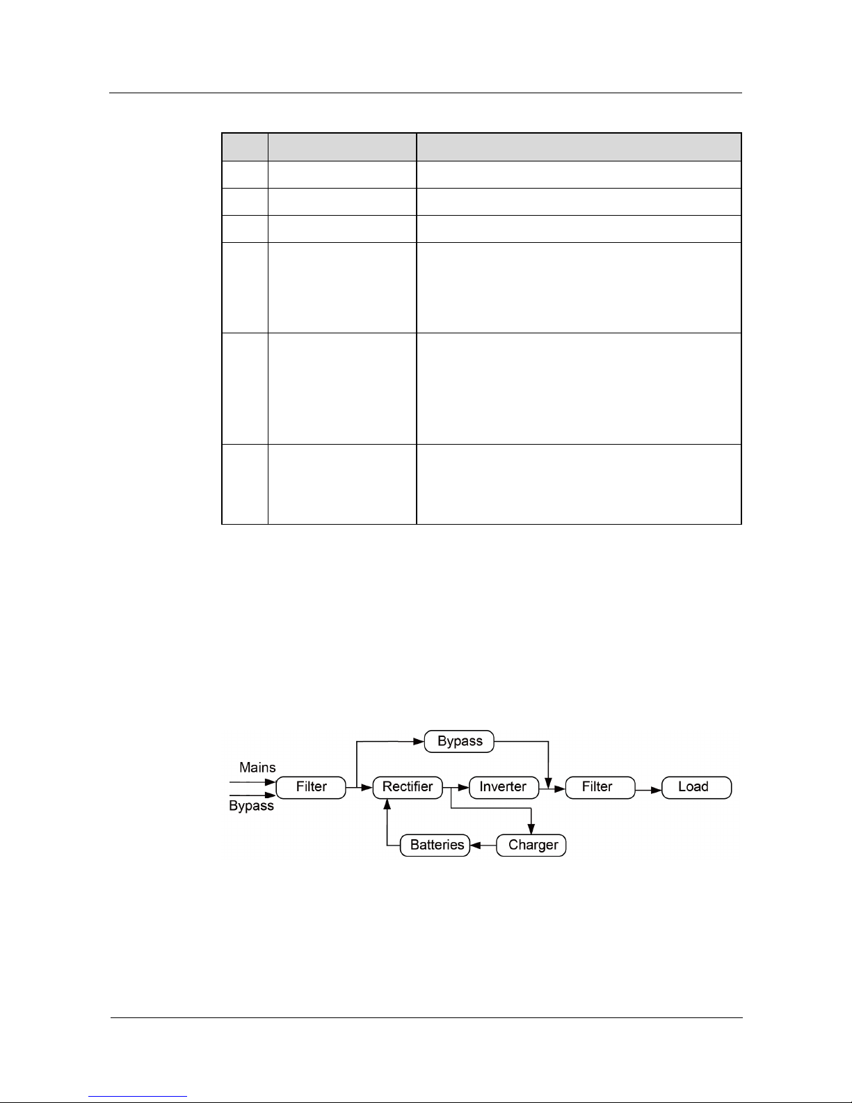
2.2.1 Conceptual Diagram
Figure 2-2 shows the UPS conceptual diagram.
Figure 2-2 Conceptual diagram
2.2.2 Working Modes
The UPS has the following working modes:
Normal mode
Page 22

UPS2000-G-(6 kVA-20 kVA)
User Manual
2 UPS2000-G-(6kVA-20kVA) Quick Introduction
Issue 10 (2017-01-19)
Huawei Proprietary and Confidential
Copyright © Huawei Technologies Co., Ltd.
14
When the mains is normal, the rectifier boosts the mains input voltage and converts the
AC power into stable DC power for the inverter, and the mains charges batteries over a
charger. Then the inverter converts the DC power into stable AC power, which is
supplied to loads.
Battery mode
When the mains is abnormal or disconnected, the DC-DC step-up transformer boosts the
DC power supplied from batteries. Then the inverter converts the DC power into stable
AC power for powering loads.
Bypass mode
The mains supplies power directly to loads after filtering. The UPS transfers to bypass
mode when overload, overtemperature, or faults occur. This mode does not provide
battery backup capability.
Economy control operation (ECO) mode
If the bypass voltage and frequency are in the specified range, the UPS supplies power to
loads over the bypass. If the bypass voltage and frequency are outside the range, the UPS
transfers to normal or battery mode. ECO is short for economy control operation.
The UPS2000-G-15 kVA/20 kVA supports battery ECO mode only in the case of two mains inputs.
In battery ECO mode, the bypass supplies power to the UPS, and batteries are used as backup power.
If the bypass is abnormal, the UPS transfers to battery mode.
By default, ECO mode described in this document refers to mains ECO mode.
2.3 Appearance
Figure 2-3 shows the front and rear views of the UPS2000-G-6 kVA. Figure 2-4 shows the
front and rear views of the UPS2000-G-10 kVA. Figure 2-5 shows the front and rear views of
the UPS2000-G-15 kVA/20 kVA.
Page 23
UPS2000-G-(6 kVA-20 kVA)
User Manual
2 UPS2000-G-(6kVA-20kVA) Quick Introduction
Issue 10 (2017-01-19)
Huawei Proprietary and Confidential
Copyright © Huawei Technologies Co., Ltd.
15
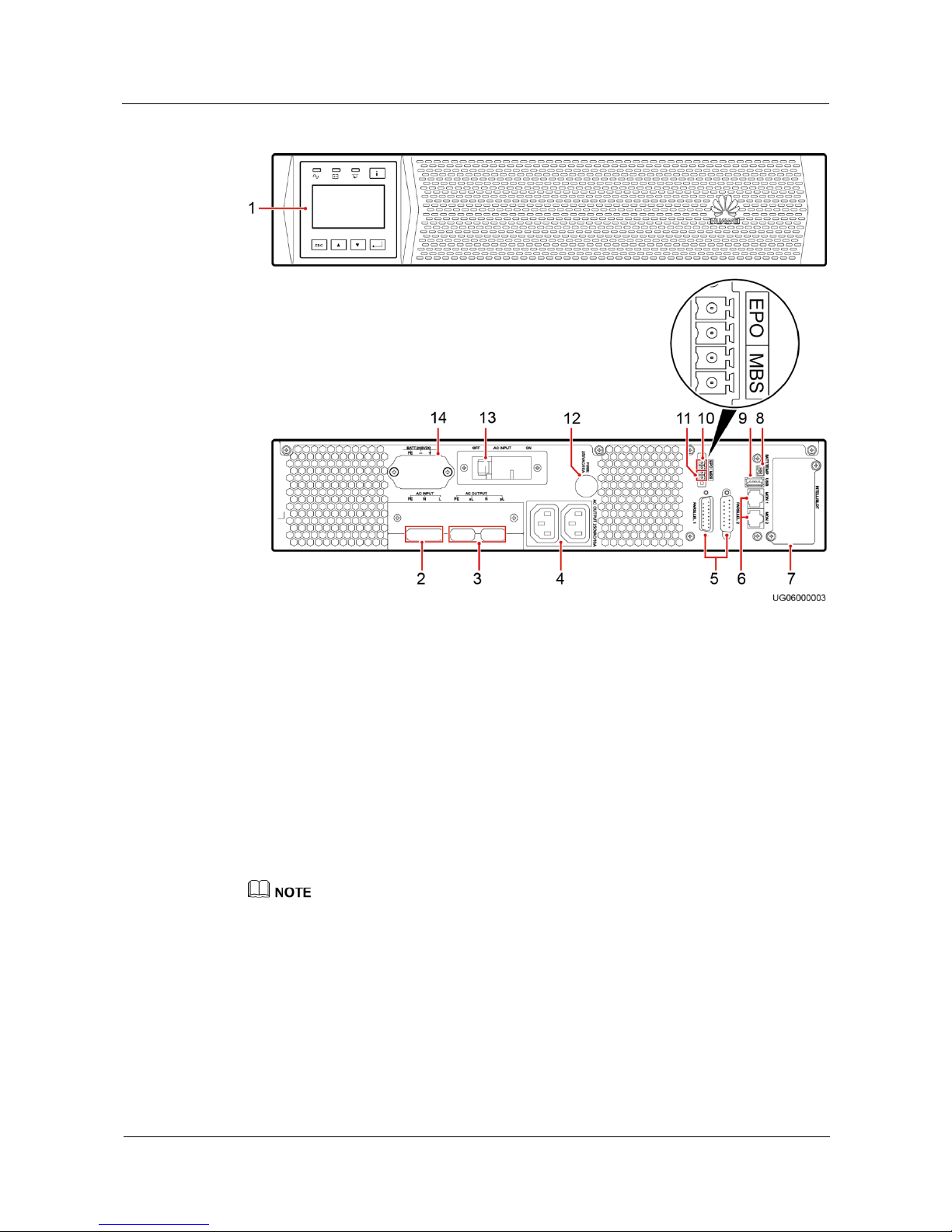
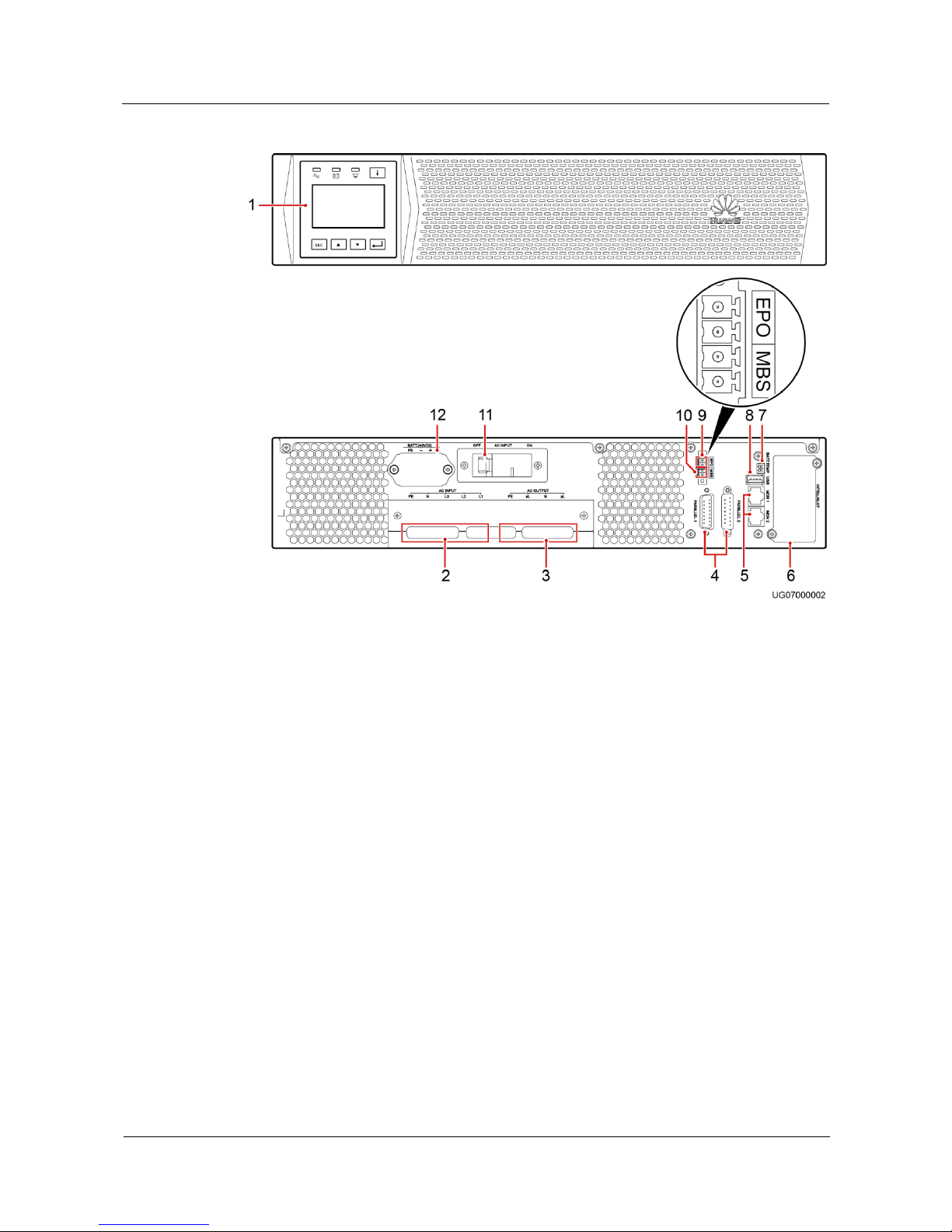
Figure 2-3 Front and rear views of the UPS2000-G-6 kVA
(1) Control
panel
(2) AC input port
(3) AC output
ports (pL and sL)
(4) Output
sockets
(5) Parallel
ports
(6) Control area network
(CAN) communications ports
(MON1 and MON2)
(7) Optional card
slot
(8) Battery
temperature
sensor port
(9) Universal
Serial Bus
(USB) port
(10) Emergency power-off
(EPO) port
(11) Maintenance
bypass port
(MBS)
(12) Fuse base
(13) Input
circuit breaker
(14) Battery port
The total load current supported by the two output sockets (C13) cannot exceed 10 A.
The fuse used on the UPS2000-G-6 kVA meets the 250V-10A-IEC specifications.
Page 24
UPS2000-G-(6 kVA-20 kVA)
User Manual
2 UPS2000-G-(6kVA-20kVA) Quick Introduction
Issue 10 (2017-01-19)
Huawei Proprietary and Confidential
Copyright © Huawei Technologies Co., Ltd.
16
Figure 2-4 Front and rear views of the UPS2000-G-10 kVA
(1) Control panel
(2) AC input ports
(3) AC output ports
(pL and sL)
(4)
Parallel
ports
(5) CAN communications
ports (MON1 and MON2)
(6) Optional card slot
(7) Battery
temperature sensor
port
(8) USB
port
(9) EPO port
(10) Maintenance
bypass port (MBS)
(11) Input circuit
breaker
(12)
Battery
port
Page 25
UPS2000-G-(6 kVA-20 kVA)
User Manual
2 UPS2000-G-(6kVA-20kVA) Quick Introduction
Issue 10 (2017-01-19)
Huawei Proprietary and Confidential
Copyright © Huawei Technologies Co., Ltd.
17
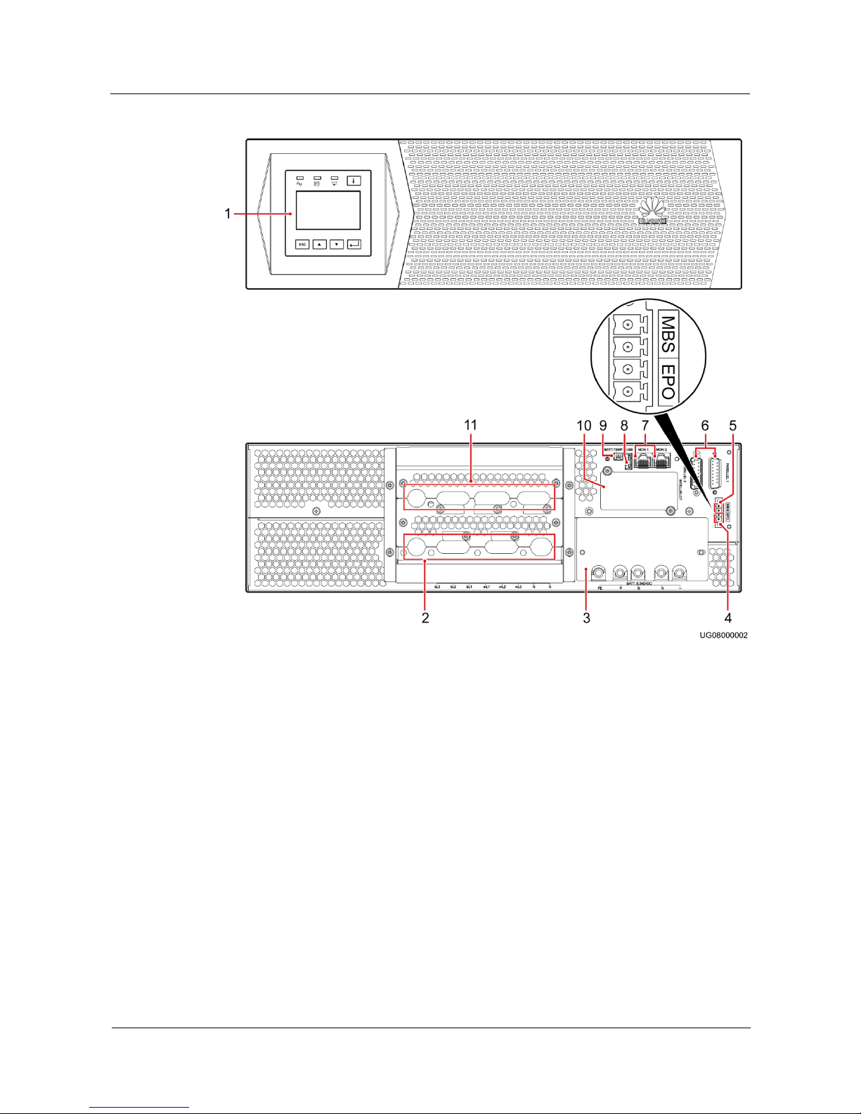
Figure 2-5 Front and rear views of the UPS2000-G-15 kVA/20 kVA
(1) Control panel
(2) AC input ports
(mains and bypass)
(3) Battery terminals
(4) EPO
port
(5) Maintenance
bypass port (MBS)
(6) Parallel ports
(7) CAN communications ports
(MON1 and MON2)
(8)
USB
port
(9) Battery
temperature sensor
port
(10) Optional card
slot
(11) AC output ports (pL and
sL)
Page 26
UPS2000-G-(6 kVA-20 kVA)
User Manual
2 UPS2000-G-(6kVA-20kVA) Quick Introduction
Issue 10 (2017-01-19)
Huawei Proprietary and Confidential
Copyright © Huawei Technologies Co., Ltd.
18
2.4 Optional Components
Table 2-2 Optional components
Compone
nt
Model
Function
Remarks
Parallel
cable
DB15M, CC8P0.48B(S),
DB15F
Connect UPSs in
parallel.
A parallel cable
is 1.5 meters
long.
Battery
temperature
sensor
TE820E10B/W103-B02-L1
Measures the ambient
temperature of the
external power module
and battery pack.
The temperature
ranges from
–40ºC to +80ºC.
The standard
cable is 2 meters
long. To increase
the length, install
a magnetic ring
at the sensor
plug. Table 2-3
lists the
specifications of
magnetic rings
from three
vendors.
Ambient
temperature
and
humidity
sensor
ENR1DETA MODULE
Measures the UPS
ambient temperature
and humidity. The
ambient temperature
ranges from 0–50ºC.
The ambient humidity
ranges from to
0%–100% RH.
It is used
together with a
Simple Network
Management
Protocol (SNMP)
card.
SNMP card
RMS-SNMP01A
Monitors the UPS and
the ambient
temperatures and
humidity (if required)
and allows for Ethernet
networking.
N/A
6 kVA
output
isolation
transformer
box
DGL-6/0.22
Provides isolation
solutions for customer
equipment. Compared
with the output
transformer on an
industrial frequency
UPS, the output
transformer box
provides isolation
functions even in
bypass mode. The
isolation transformer is
The output
isolation
transformer box
is 6 kVA,
single-phase. It is
used for the
UPS2000-G-6
kVA.
10 kVA
output
isolation
DGL-10/0.22
The output
isolation
transformer box
Page 27

UPS2000-G-(6 kVA-20 kVA)
User Manual
2 UPS2000-G-(6kVA-20kVA) Quick Introduction
Issue 10 (2017-01-19)
Huawei Proprietary and Confidential
Copyright © Huawei Technologies Co., Ltd.
19
Compone
nt
Model
Function
Remarks
transformer
box
a 2:1:1
industrial-frequency
transformer. It converts
one 220 V output
voltage into two
isolated 110 V outputs.
is 10 kVA,
single-phase. It is
used for the
UPS2000-G-10
kVA.
Standard
battery pack
(7 Ah, 20
batteries)
ESS-240V12-7AhBPVBA01
ESS-240V12-7AhBPVBA02
Each battery pack
consists of twenty 12 V,
7 Ah VRLA batteries
connected in series. It is
a standard configuration
for the UPS2000-G-6
kVA. A maximum of
four battery packs are
connected in parallel.
The
UPS2000-G-15
kVA/20 kVA
uses at least two
battery packs.
Standard
battery pack
(9 Ah, 20
batteries)
ESS-240V12-9AhBPVBA01
ESS-240V12-9AhBPVBA02
Each battery pack
consists of twenty 12 V,
9 Ah VRLA batteries
connected in series. It is
a standard configuration
for the UPS2000-G-10
kVA. A maximum of
four battery packs are
connected in parallel.
Modbus
card
RMS-MODBUS01A
Provides two cascaded
RJ45 ports to
implement networking
over the Modbus or
YDN-23 protocol.
N/A
Dry contact
card
RMS-RELAY01A
Provides six alarm dry
contact outputs (normal
mode, battery mode,
bypass mode, low
battery voltage, bypass
backfeed, and UPS
faults) and two dry
contract control inputs
(one is the shutdown
signal input, and the
other is reserved).
N/A
External dry
contact card
RMS-RELAY02B
Provides four dry
contact outputs (critical
alarm, minor alarm,
mains mode, battery
mode, bypass mode,
inverter on, battery
undervolt.,bypass
backfeed , high ambient
tempreture, or UPS
Used together
with an SNMP
card.
Page 28
UPS2000-G-(6 kVA-20 kVA)
User Manual
2 UPS2000-G-(6kVA-20kVA) Quick Introduction
Issue 10 (2017-01-19)
Huawei Proprietary and Confidential
Copyright © Huawei Technologies Co., Ltd.
20
Compone
nt
Model
Function
Remarks
fault.) and two dry
contract inputs (startup,
shutdown).
iBAT 2.0
-
Consists of the
communication
interface module (CIM)
and battery interface
module (BIM). The
CIM is an intelligent
battery management
module which collects
wireless communication
data of battery stauts
from the downstream
BIM groups, and
uploads data to the
SNMP card through the
COM port.
Used together
with an SNMP
card.
Power
distribution
unit (PDU)
(PDC-0038
V4ACIOA)
PDC-0038V4ACIOA
Controls and protects
input and output power,
increases output
sockets, and distributes
power for 1+1 parallel
systems, and
implements online
maintenance.
The PDU is
designed for a
1+1
UPS2000-G-15
kVA/20 kVA
parallel system
(three-phase
input three-phase
output).
PDU
(PDC-0091
V2ACIOA)
PDC-0091V2ACIOA
The PDU is
designed for a
1+1
UPS2000-G15 kVA/20
kVA parallel
system
(three-phase
input
single-phase
output and
single-phase
input
single-phase
output).
It can also be
used in a
UPS2000-G6 kVA/10
kVA 1+1
parallel
system and
2+0 parallel
Page 29

UPS2000-G-(6 kVA-20 kVA)
User Manual
2 UPS2000-G-(6kVA-20kVA) Quick Introduction
Issue 10 (2017-01-19)
Huawei Proprietary and Confidential
Copyright © Huawei Technologies Co., Ltd.
21
Compone
nt
Model
Function
Remarks
system.
Magnetic
loop
DN85H, H38x22x15
(DMEGC)
E2F, 38x22x15 (FENGYI)
Optimizes the
performance of the
TN-C power
distribution system in
the parallel system
scenario.
In a
UPS2000-G-15
kVA/20 kVA
parallel system
using the TN-C
power
distribution
system, install
four magnetic
rings on the PE
cables on each
UPS, bind the
four magnetic
rings together
using binding
tape, and secure
them to the
nearest place.
NOTE
The
application
scenarios of
magnetic
rings are
described
below.
Figure 2-6
and Figure
2-7 show the
magnetic ring
installation
method and
position.
It is recommended that you install the battery temperature sensor (secured with an adhesive) on the
surface of batteries in the middle of the battery rack.
In a UPS2000-G-15 kVA/20 kVA parallel system using the TN-C power distribution system,
there are two scenarios for installing magnetic rings on the UPS mains input PE cables:
One is to install magnetic rings on branch PE cables (see Figure 2-6).
The other is to install a magnetic ring on the general PE cable (see Figure 2-7).
For magnetic ring specifications, see section Table 2-2.
Page 30
UPS2000-G-(6 kVA-20 kVA)
User Manual
2 UPS2000-G-(6kVA-20kVA) Quick Introduction
Issue 10 (2017-01-19)
Huawei Proprietary and Confidential
Copyright © Huawei Technologies Co., Ltd.
22
Figure 2-6 Installing magnetic rings (numbered 1) on branch PE cables
Page 31

UPS2000-G-(6 kVA-20 kVA)
User Manual
2 UPS2000-G-(6kVA-20kVA) Quick Introduction
Issue 10 (2017-01-19)
Huawei Proprietary and Confidential
Copyright © Huawei Technologies Co., Ltd.
23
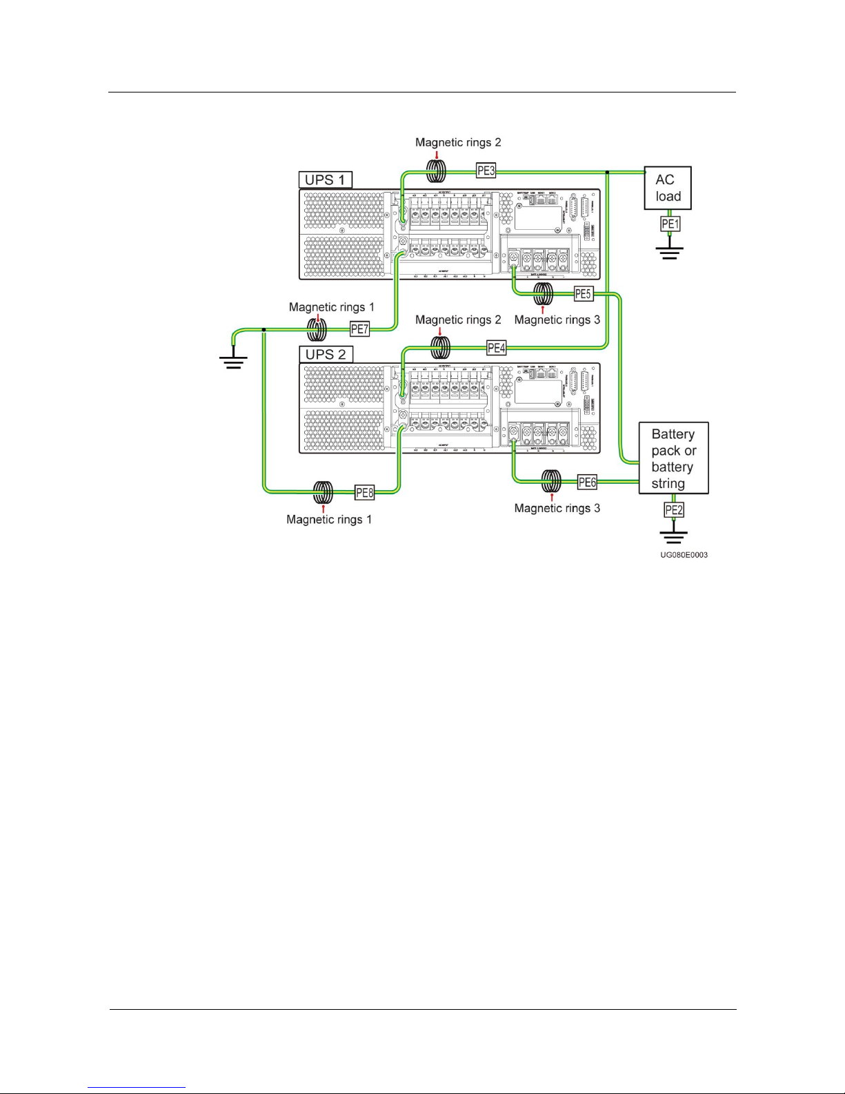
Figure 2-7 Installing a magnetic ring (numbered 1) on the general PE cable
Perform the following operations in a parallel system using the TN-C power distribution system:
Short-circuit battery terminals N in the parallel system.
It is recommended that you connect AC loads and battery packs only to the UPS PE terminal.
If you have directly grounded AC loads and battery packs (as shown by PE1 and PE2 in Figure 2-6)
and connected them to the UPS PE terminal, install magnetic rings 2 and 3 on the PE3, PE4, PE5,
and PE6 ground cables. You need to purchase magnetic rings 2 and 3.
The recommended type for magnetic rings 1, 2, and 3 is DN85Hx4 or E2Fx4. For details, see Table
2-2.
Table 2-3 Specifications of magnetic rings from three vendors
Vendor
Magnetic Ring
DMEGC
R10K
TDK
HS10
TDG
TS10
Page 32

UPS2000-G-(6 kVA-20 kVA)
User Manual
2 UPS2000-G-(6kVA-20kVA) Quick Introduction
Issue 10 (2017-01-19)
Huawei Proprietary and Confidential
Copyright © Huawei Technologies Co., Ltd.
24
The magnetic conductivity of manganese and zinc magnetic rings is greater than 10,000, and the
recommended internal diameter of magnetic rings is greater than 10 mm (easy for wire coiling). The
number of coiling circles is 5 or greater.
Page 33

UPS2000-G-(6 kVA-20 kVA)
User Manual
3 Installation
Issue 10 (2017-01-19)
Huawei Proprietary and Confidential
Copyright © Huawei Technologies Co., Ltd.
25
3 Installation
3.1 Preparations
3.1.1 Site
Floor Bearing
The floor can bear the weight of the UPS and its optional components. In the case of rack
installation, ensure that the floor can also bear the weight of the rack.
For the UPS weight, see section 9.1 Physical Specifications.
Environment
Do not install the UPS in an environment outside the specifications (see section 9.2
Environmental Specifications).
Keep the UPS far away from water, heat sources, and flammable and explosive
substances. Install the UPS in an environment free of dust, volatile gas, salt, and
corrosive materials. Avoid direct sunlight.
Do not install the UPS in environments with conductive metal scraps in the air.
The ideal operating temperature for batteries is 20–30ºC. Temperatures higher than 30ºC
shorten the battery lifespan and temperatures lower than 20ºC reduces the backup time.
Page 34

UPS2000-G-(6 kVA-20 kVA)
User Manual
3 Installation
Issue 10 (2017-01-19)
Huawei Proprietary and Confidential
Copyright © Huawei Technologies Co., Ltd.
26
UPS2000-G-6 kVA/10 kVA Dimensions
Figure 3-1 UPS2000-G-6 kVA/10 kVA installation dimensions
UPS2000-G-15 kVA/20 kVA Dimensions
Figure 3-2 UPS2000-G-15 kVA/20 kVA installation dimensions
Clearances
Page 35

UPS2000-G-(6 kVA-20 kVA)
User Manual
3 Installation
Issue 10 (2017-01-19)
Huawei Proprietary and Confidential
Copyright © Huawei Technologies Co., Ltd.
27
The distance between UPS air vents and the wall or obstacle is greater than or equal to 500
mm.
Reserve a clearance of at least 500 mm respectively from the front and rear panels of the UPS
to the wall or adjacent equipment to facilitate ventilation and heat dissipation, as shown in
Figure 3-3.
Figure 3-3 Reserved clearances
3.1.2 Tools
Get installation tools insulated to prevent electric shocks.
Table 3-1 lists the installation tools.
Table 3-1 Tools
Tools
Clamp meter
Multimeter
Label
Phillips
screwdriver (PH 2
x 150 mm or PH 3
x 250 mm)
Page 36

UPS2000-G-(6 kVA-20 kVA)
User Manual
3 Installation
Issue 10 (2017-01-19)
Huawei Proprietary and Confidential
Copyright © Huawei Technologies Co., Ltd.
28
Tools
Flat-head
screwdriver (2 mm
x 80 mm)
Torque screwdriver
Crimping tool
Diagonal pliers
Wire stripper
Polyvinyl chloride
(PVC) insulation tape
Cotton cloth
Brush
Heat shrink tubing
Heat gun
Electrician's knife
Protective gloves
ESD gloves
Insulated gloves
Hydraulic pliers
Cable tie
3.1.3 Power Cables
Page 37

UPS2000-G-(6 kVA-20 kVA)
User Manual
3 Installation
Issue 10 (2017-01-19)
Huawei Proprietary and Confidential
Copyright © Huawei Technologies Co., Ltd.
29
In the case of three-phase input, install a three-phase disconnector. In the case of
single-phase input, you are advised to install a disconnector.
When used to power IT system, the UPS (three-phase output) should provide 4-pole
disconnectors, and the UPS (single-phase output) should provide 2-pole disconnectors.
The UPS is a large leakage current device. Do not configure a circuit breaker that has the
leakage current protection function. If you need leakage current protection function, use
the earth leakage circuit breaker recommended.
The battery cable cannot be longer than 10 m.
You can install linked circuit breakers for both the N wire and L wire. No independent
circuit breaker is allowed for only the N wire.
For 15 kVA/20 kVA model, use AC ground cables that have a cross-sectional area of 25
mm2 and M6 OT terminals that are 90° bent and have a cross-sectional area of 25 mm2.
For 15 kVA/20 kVA model, use battery ground cables that have a cross-sectional area of
16 mm2 and M6 OT terminals that are 90° bent and have a cross-sectional area of 16 mm2.
For 6 kVA model, use ground cables that have a cross-sectional area of 6 mm2 and M4 OT
terminals and have a cross-sectional area of 6 mm2.
For 10 kVA model, use ground cables that have a cross-sectional area of 10 mm2 and M6
OT terminals and have a cross-sectional area of 10 mm2.
Table 3-2 lists the recommended power cable specifications.
Table 3-2 Recommended power cable specifications
Model
Wiri
ng
Term
inal
Nu
mbe
r of
Pha
ses
Rated
Voltage
Extern
al
Circui
t
Break
er
Earth
Leaka
ge
Circui
t
Break
er
(ELCB
)
Crosssectio
nal
Area
Termi
nal
Type
Torq
ue
for
Tight
ening
Bolts
6 kVA
Input
1
220 V
AC, 230
V AC, or
240 V AC
50 A
(the
charact
eristics
of D)
100
mA
6 mm2
6 mm2
M4 OT
termina
l
1.4
N·m
Outpu
t
1
50 A
(the
charact
eristics
of D)
N/A
Batter
y
N/A
240 V DC
50 A
N/A
6 mm2
N/A
10 kVA
Input
1
220 V
AC, 230
63 A
(the
100
10 mm2
10 mm2
M6 OT
2.8
Page 38

UPS2000-G-(6 kVA-20 kVA)
User Manual
3 Installation
Issue 10 (2017-01-19)
Huawei Proprietary and Confidential
Copyright © Huawei Technologies Co., Ltd.
30
Model
Wiri
ng
Term
inal
Nu
mbe
r of
Pha
ses
Rated
Voltage
Extern
al
Circui
t
Break
er
Earth
Leaka
ge
Circui
t
Break
er
(ELCB
)
Crosssectio
nal
Area
Termi
nal
Type
Torq
ue
for
Tight
ening
Bolts
V AC, or
240 V AC
charact
eristics
of D)
mA
termina
l
N·m
Outpu
t
1
63 A
(the
charact
eristics
of D)
N/A
Input
3
380 V
AC, 400
V AC, or
415 V AC
63 A
(the
charact
eristics
of D)
100
mA
10 mm2
Outpu
t
1
220 V
AC, 230
V AC, or
240 V AC
63 A
(the
charact
eristics
of D)
N/A
Batter
y
N/A
240 V DC
63 A
N/A
10 mm2
N/A
15 kVA
(single-ph
ase input
single-pha
se output)
One
mains
input
1
220 V
AC, 230
V AC, or
240 V AC
100 A
(the
charact
eristics
of D)
300
mA
25 mm2
25 mm2
M6 OT
termina
l
4.8
N·m
Batter
y
N/A
±240 V
DC
63 A
N/A
16 mm2
16 mm2
M6 90°
OT
termina
l
4.8
N·m
Outpu
t
1
220 V
AC, 230
V AC, or
240 V AC
100 A
(the
charact
eristics
of D)
N/A
25 mm2
25 mm2
M6 OT
termina
l
4.8
N·m
15 kVA
(three-pha
se input
single-pha
Bypas
s
input
1
220 V
AC, 230
V AC, or
240 V AC
100 A
(the
charact
eristics
300
mA
25 mm2
25 mm2
M6 OT
termina
l
4.8
N·m
Page 39

UPS2000-G-(6 kVA-20 kVA)
User Manual
3 Installation
Issue 10 (2017-01-19)
Huawei Proprietary and Confidential
Copyright © Huawei Technologies Co., Ltd.
31
Model
Wiri
ng
Term
inal
Nu
mbe
r of
Pha
ses
Rated
Voltage
Extern
al
Circui
t
Break
er
Earth
Leaka
ge
Circui
t
Break
er
(ELCB
)
Crosssectio
nal
Area
Termi
nal
Type
Torq
ue
for
Tight
ening
Bolts
se output)
of D)
Mains
input
3
380 V
AC, 400
V AC, or
415 V AC
50 A
(the
charact
eristics
of D)
300
mA
10 mm2
10 mm2
M6 OT
termina
l
2.8
N·m
Batter
y
N/A
±240 V
DC
63 A
N/A
16 mm2
16 mm2
M6 90°
OT
termina
l
4.8
N·m
Outpu
t
1
220 V
AC, 230
V AC, or
240 V AC
100 A
(the
charact
eristics
of D)
N/A
25 mm2
25 mm2
M6 OT
termina
l
4.8
N·m
15 kVA
(three-pha
se input
three-phas
e output)
Bypas
s
input
3
380 V
AC, 400
V AC, or
415 V AC
50 A
(the
charact
eristics
of D)
300
mA
10 mm2
10 mm2
M6 OT
termina
l
2.8
N·m
Mains
input
3
300
mA
Batter
y
N/A
±240 V
DC
63 A
N/A
16 mm2
16 mm2
M6 90°
OT
termina
l
4.8
N·m
Outpu
t
3
380 V
AC, 400
V AC, or
415 V AC
50 A
(the
charact
eristics
of D)
N/A
10 mm2
10 mm2
M6 OT
termina
l
2.8
N·m
20 kVA
(single-ph
ase input
single-pha
se output)
One
mains
input
1
220 V
AC, 230
V AC, or
240 V AC
125 A
(the
charact
eristics
of D)
Adjusta
ble
from
500
mA to
1000
mA
25 mm2
25 mm2
M6 OT
termina
l
4.8
N·m
Page 40

UPS2000-G-(6 kVA-20 kVA)
User Manual
3 Installation
Issue 10 (2017-01-19)
Huawei Proprietary and Confidential
Copyright © Huawei Technologies Co., Ltd.
32
Model
Wiri
ng
Term
inal
Nu
mbe
r of
Pha
ses
Rated
Voltage
Extern
al
Circui
t
Break
er
Earth
Leaka
ge
Circui
t
Break
er
(ELCB
)
Crosssectio
nal
Area
Termi
nal
Type
Torq
ue
for
Tight
ening
Bolts
Batter
y
NA
±240 V
DC
63 A
N/A
16 mm2
16 mm2
M6 90°
OT
termina
l
4.8
N·m
Outpu
t
1
220 V
AC, 230
V AC, or
240 V AC
125 A
(the
charact
eristics
of D)
N/A
25 mm2
25 mm2
M6 OT
termina
l
4.8
N·m
20 kVA
(three-pha
se input
single-pha
se output)
Bypas
s
input
1
220 V
AC, 230
V AC, or
240 V AC
125 A
(the
charact
eristics
of D)
Adjusta
ble
from
500
mA to
1000
mA
25 mm2
25 mm2
M6 OT
termina
l
4.8
N·m
Mains
input
3
380 V
AC, 400
V AC, or
415 V AC
63 A
(the
charact
eristics
of D)
300
mA
10 mm2
10 mm2
M6 OT
termina
l
2.8
N·m
Batter
y
N/A
±240 V
DC
63 A
N/A
16 mm2
16 mm2
M6 90°
OT
termina
l
4.8
N·m
Outpu
t
1
220 V
AC, 230
V AC, or
240 V AC
125 A
(the
charact
eristics
of D)
N/A
25 mm2
25 mm2
M6 OT
termina
l
4.8
N·m
20 kVA
(three-pha
se input
three-phas
e output)
Bypas
s
input
3
380 V
AC, 400
V AC, or
415 V AC
63 A
(the
charact
eristics
of D)
300
mA
10 mm2
10 mm2
M6 OT
termina
l
2.8
N·m
Mains
input
3
300
mA
Batter
N/A
±240 V
63 A
N/A
16 mm2
16 mm2
M6 90°
4.8
Page 41

UPS2000-G-(6 kVA-20 kVA)
User Manual
3 Installation
Issue 10 (2017-01-19)
Huawei Proprietary and Confidential
Copyright © Huawei Technologies Co., Ltd.
33
Model
Wiri
ng
Term
inal
Nu
mbe
r of
Pha
ses
Rated
Voltage
Extern
al
Circui
t
Break
er
Earth
Leaka
ge
Circui
t
Break
er
(ELCB
)
Crosssectio
nal
Area
Termi
nal
Type
Torq
ue
for
Tight
ening
Bolts
y
DC
OT
termina
l
N·m
Outpu
t
3
380 V
AC, 400
V AC, or
415 V AC
63 A
(the
charact
eristics
of D)
N/A
10 mm2
10 mm2
M6 OT
termina
l
2.8
N·m
If customers purchase input and output power cables by themselves, use the cables that comply with
standards proposed by Underwriters Laboratories (UL) or International Electrotechnical
Commission (IEC).
Two-mains-input scenarios are not supported on the UPS2000-G-15 kVA/20 kVA (single-phase
input single-phase output).
3.1.4 Unpacking and Checking
Figure 3-4 shows the transportation safety requirements.
Figure 3-4 Transportation safety requirements
Page 42

UPS2000-G-(6 kVA-20 kVA)
User Manual
3 Installation
Issue 10 (2017-01-19)
Huawei Proprietary and Confidential
Copyright © Huawei Technologies Co., Ltd.
34
Only trained personnel are allowed to move the UPS.
Do not move the UPS by holding its mounting brackets, front panel, terminal cover, or
monitoring module.
At least two persons are required to move the battery pack and transformer because they
are heavy. Exercise caution when moving them. Prevent the battery pack from falling over;
otherwise, fire accidents may occur. Remove rings, watches, and other metal objects when
you move the battery pack.
To prevent shocks or falls, move the UPS gently. After placing the UPS in the installation
position, unpack it carefully to prevent scratches.
Procedure
Step 1 Visually inspect the UPS appearance for shipping damage. If any shipping damage is found,
report it to the carrier immediately.
Step 2 Move the UPS to the installation position.
Step 3 Unpack the case.
Step 4 Check the UPS packing.
1. Check the UPS bar code (which is at the rear panel of the UPS, near the air exhaust vent),
and ensure that it complies with the order.
2. If there is any discrepancy, contact your local Huawei office immediately.
----End
3.2 Single UPS/Parallel System Installation
UPS installation includes mechanical installation and cable connection. Installation modes
include tower installation and rack installation. You can select an installation mode based on
the site requirements.
For details, see the UPS2000-G-(6 kVA-10 kVA) Quick Guide and UPS2000-G-(15 kVA-20
kVA) Quick Guide.
The UPS2000-G-(6 kVA-10 kVA) Quick Guide and UPS2000-G-(15 kVA-20 kVA) Quick Guide delivered
with the UPS.
3.3 Installing a Backfeed Protection Device
Page 43

UPS2000-G-(6 kVA-20 kVA)
User Manual
3 Installation
Issue 10 (2017-01-19)
Huawei Proprietary and Confidential
Copyright © Huawei Technologies Co., Ltd.
35
The UPS has no built-in backfeed protection device. You can install a backfeed protection
device on the input front side.
If you do no install a backfeed protection device on the input front side, attach a warning label
to the main power isolation device. The label reads like this: "This circuit supplies power to
the UPS. Before cable connection, disconnect the UPS, and check the voltage across wiring
terminals."
When battery mode is unavailable or the mains fails, the UPS internal voltages or energy may
flow back directly, or through a leakage path, to an input terminal. To minimize the risk of
electric shocks, install a backfeed protection device on the input side.
Table 3-3 lists the rated voltages and currents for backfeed protection contactors on the UPSs.
Table 3-3 Rated voltages and currents for backfeed protection contactors
Model
Rated Voltage and Current
Recommended
Contactor Models
(Schneider contactors)
UPS2000-G-6KRTS
220/230/240 V AC, 40 A
LC1-D40A
UPS2000-G-6KRTL
UPS2000-G-10KRTS
220/230/240 V AC, 65 A
LC1-D50A for
single-phase input
LC1-DT60A for
three-phase input
UPS2000-G-10KRTL
UPS2000-G-15KRTL
(three-phase input)
220/230/240 V AC, 32 A
LC1-D80 for
single-phase input
LC1-DT60A for
three-phase input
UPS2000-G-20KRTL
(three-phase input)
220/230/240 V AC, 40 A
UPS2000-G-15KRTL
(single-phase input)
UPS2000-G-20KRTL
(single-phase input)
220/230/240 V AC, 125 A
Table 3-4 Control relay parameters
Recommended Model
Parameters
HF18FF/012 (HONGFA control relay)
Dry contact: NC
Breaking capability: 250 V AC, 5 A
Coil: 12 V rated voltage; rated current of
less than 1 A
MY2N-J DC12V (OMRON control relay)
HJ2-L-DC12V (Panasonic control relay)
Page 44

UPS2000-G-(6 kVA-20 kVA)
User Manual
3 Installation
Issue 10 (2017-01-19)
Huawei Proprietary and Confidential
Copyright © Huawei Technologies Co., Ltd.
36
3.3.1 Feedback Prevention Connections (With Dry Contract
Control)
Figure 3-5, Figure 3-6, Figure 3-7 and Figure 3-8 show backfeed protection connections (with
dry contract control).
Figure 3-5 Bypass backfeed protection connections for the UPS2000-G-6 kVA/10 kVA/15
kVA/20 kVA (single-phase input single-phase output)
Page 45

UPS2000-G-(6 kVA-20 kVA)
User Manual
3 Installation
Issue 10 (2017-01-19)
Huawei Proprietary and Confidential
Copyright © Huawei Technologies Co., Ltd.
37
Figure 3-6 Bypass backfeed protection connections for the UPS2000-G-10 kVA (three-phase
input single-phase output)
Page 46

UPS2000-G-(6 kVA-20 kVA)
User Manual
3 Installation
Issue 10 (2017-01-19)
Huawei Proprietary and Confidential
Copyright © Huawei Technologies Co., Ltd.
38
Figure 3-7 Bypass backfeed protection connections for the UPS2000-G-15 kVA/20 kVA
(three-phase input three-phase output)
Page 47

UPS2000-G-(6 kVA-20 kVA)
User Manual
3 Installation
Issue 10 (2017-01-19)
Huawei Proprietary and Confidential
Copyright © Huawei Technologies Co., Ltd.
39
Figure 3-8 Bypass backfeed protection connections for the UPS2000-G-15 kVA/20 kVA
(three-phase input single-phase output)
3.4 Check After Installation
Table 3-5 lists the check items.
Table 3-5 Post-installation check items
No.
Item
Expected Result
1
Cable routing
Cable routing meets engineering requirements.
2
Cable connections
Input cables, output cables, and battery cables are
tightened to specified torques using a torque
wrench, connected correctly, and free of damage.
Page 48

UPS2000-G-(6 kVA-20 kVA)
User Manual
3 Installation
Issue 10 (2017-01-19)
Huawei Proprietary and Confidential
Copyright © Huawei Technologies Co., Ltd.
40
No.
Item
Expected Result
3
Cable connections for USB
ports and network ports
Cables to USB ports and network ports are
connected correctly and securely.
4
Labels
Labels are neatly attached to both ends of each
cable, and the information on the labels is
concise and understandable.
5
Ground cable connection
The ground cable is securely connected to the
equipment room ground bar. Measure the
resistance between the UPS ground cable and the
equipment room ground bar, which must be less
than 1 ohm.
6
Distances between cable ties
Distances between cable ties are the same, and no
burr exists.
7
Operating environment
Clean the conductive air and other sundries.
Page 49

UPS2000-G-(6 kVA-20 kVA)
User Manual
4 Control Panel
Issue 10 (2017-01-19)
Huawei Proprietary and Confidential
Copyright © Huawei Technologies Co., Ltd.
41
4 Control Panel
4.1 Introduction
The control panel, located on the front panel of the UPS, controls UPS running, displays
running data, and allows you to set parameters and view alarms. Figure 4-1 shows the control
panel.
Figure 4-1 Control panel
(1) Mains indicator
(2) Battery
indicator
(3) Bypass
indicator
(4) Fault
indicator/INFO button
(5) Startup/Enter/Battery
Self-Check/Mute button
(6) Down
button
(7) Up button
(8) Shutdown/Back
button
4.2 Indicators
Table 4-1 describes the indicators on the control panel.
Page 50

UPS2000-G-(6 kVA-20 kVA)
User Manual
4 Control Panel
Issue 10 (2017-01-19)
Huawei Proprietary and Confidential
Copyright © Huawei Technologies Co., Ltd.
42
Table 4-1 Indicator description
Indicator
Color
Status
Meaning
Mains indicator
Green
On
The UPS is in normal mode.
Off
The UPS is not in normal mode.
Battery indicator
Yellow
On
The UPS is in battery mode.
Off
The UPS is not in battery mode.
Blinking
The remaining battery capacity is less
than 25%.
Bypass indicator
Yellow
On
The UPS is in bypass mode.
Off
The UPS is not in bypass mode.
Fault indicator/INFO
button
Red
On
The UPS is faulty.
Red
Blinking
The UPS generates an alarm.
Green
On
The UPS is running properly.
The UPS is in ECO mode when the mains indicator and bypass indicator are both on.
4.3 Functional Buttons
The control panel provides five buttons to start and shut down the UPS and set parameters.
Table 4-2 describes the buttons.
Table 4-2 Button description
Butt
on
Meaning
Description
ESC
Shutdown/Back
On the default screen, press ESC for more than 5
seconds. Release the button when you hear a
beep sound. The inverter shuts down.
On any other screen, press ESC to return to the
upper-level menu (the default screen is the
upper-level screen for the main menu screen).
▲
Up
Press ▲ or ▼ to scroll upward or downward.
You can set a value by using the list or step increase
or decrease.
▼
Down
Enter/Startup/Battery
Self-Check/Mute
On the default screen in bypass mode, hold down
for more than 5 seconds. Release the
button when you hear a beep sound. The UPS
starts.
Page 51

UPS2000-G-(6 kVA-20 kVA)
User Manual
4 Control Panel
Issue 10 (2017-01-19)
Huawei Proprietary and Confidential
Copyright © Huawei Technologies Co., Ltd.
43
Butt
on
Meaning
Description
On the default screen, press . The main
menu is displayed.
On any menu screen, press . The
lower-level menu is displayed. If the menu is the
last level, an information screen is displayed.
On the default screen in normal mode, hold down
for more than 5 seconds. Release the
button when you hear a beep sound. The battery
test starts.
When the buzzer buzzes, hold down for
2–5 seconds. The buzzer is muted when you
release the button.
i
Fault indicator/INFO
button
When an alarm is generated, press i to view the
active alarm information.
When no alarm is generated, press i to return to
the default screen.
Battery self-check: After the UPS starts in normal mode, it transfers to battery mode for 10 seconds
to check that the battery status (if no battery is connected, No battery is displayed) and that the UPS
can transfer to battery mode. The purpose is to prevent power backup failure when the UPS needs to
transfer to battery mode.
If you do not press any button within 60 seconds, the default screen is displayed.
4.4 LCD
The LCD displays the UPS running data and alarm information, and allows you to set
parameters and control operation. The backlight turns off if you do not press any button
within 30 seconds.
4.5 LCD Startup Screens
Table 4-3 Symbol conventions
Symbol
Description
Press A.
Press B after you press A.
Indicates omitted screens.
Page 52

UPS2000-G-(6 kVA-20 kVA)
User Manual
4 Control Panel
Issue 10 (2017-01-19)
Huawei Proprietary and Confidential
Copyright © Huawei Technologies Co., Ltd.
44
The symbol conventions apply to all chapters in this document.
The LCD figures in this document correspond to V100R001C10SPC802. The LCD
updated without notice. If the LCD is updated, contact Huawei for the latest LCD figures.
The screen in this document based on the UPS2000-G-15 kVA/20 kVA. The parameter
values in the menu pictures in this document are for reference only.
Figure 4-2 shows a startup screen.
Figure 4-2 Description of the startup screen
(1) Normal mode (The solid line indicates
normal mode. The dotted line indicates
non-normal mode.)
(2) Input voltage and frequency
(3) Load power
(4) Output voltage, current, and frequency
(5) Bypass mode (The solid line indicates
bypass mode. The dotted line indicates
non-bypass mode.)
(6) Battery voltage and capacity displayed
during charge; Battery discharge time and
capacity displayed during discharge.
(7) Battery mode (The solid line indicates
battery in charge or discharge mode. The
dotted line indicates non-battery mode.)
Table 4-4 describes the icons on the screen.
Page 53

UPS2000-G-(6 kVA-20 kVA)
User Manual
4 Control Panel
Issue 10 (2017-01-19)
Huawei Proprietary and Confidential
Copyright © Huawei Technologies Co., Ltd.
45
Table 4-4 Icons on the screen
Icon
Meaning
Icon
Meaning
Mains input
Rectifier/Power
factor correction
(PFC) working
Inverter working
Bypass mode
Load power
Battery charging
Battery discharging
N/A
N/A
4.5.1 Starting the UPS in Normal Mode
Initial Startup
The settings wizard starts automatically when you start the UPS for the first time or when you
restart the UPS after restoring factory settings, as shown in Figure 4-3. The settings wizard
provides the Language, System Parameters, and Battery Parameters screens.
Figure 4-3 Settings wizard
After you complete the settings, press . The standby screen is displayed.
Page 54

UPS2000-G-(6 kVA-20 kVA)
User Manual
4 Control Panel
Issue 10 (2017-01-19)
Huawei Proprietary and Confidential
Copyright © Huawei Technologies Co., Ltd.
46
Figure 4-4 Standby screen displayed after initial startup
Non-initial Startup
When the initialization is complete, the standby screen is displayed.
Figure 4-5 Standby screen displayed after non-initial startup
After the UPS starts, it enters normal mode. For the startup procedure, see chapter 5
Operations.
Figure 4-6 Normal mode
Press . The main menu screen is displayed.
4.5.2 Starting the UPS in Battery Mode
Initial Startup
The settings wizard starts automatically when you start the UPS for the first time or when you
restart the UPS after restoring factory settings. The settings wizard provides the Language,
System Parameters, and Battery Parameters screens.
After you complete the settings, press . The standby screen is displayed.
Page 55

UPS2000-G-(6 kVA-20 kVA)
User Manual
4 Control Panel
Issue 10 (2017-01-19)
Huawei Proprietary and Confidential
Copyright © Huawei Technologies Co., Ltd.
47
Figure 4-7 Standby screen displayed after initial startup
Non-initial Startup
When the initialization is complete, the standby screen is displayed.
Figure 4-8 Standby screen displayed after non-initial startup
After the UPS starts, it enters battery mode. For the startup procedure, see 5 Operations.
Figure 4-9 Battery mode
Press . The main menu screen is displayed.
4.6 LCD Menu Hierarchy
Figure 4-10 Main Menu screen
Figure 4-11 shows the LCD menu hierarchy.
Page 56

UPS2000-G-(6 kVA-20 kVA)
User Manual
4 Control Panel
Issue 10 (2017-01-19)
Huawei Proprietary and Confidential
Copyright © Huawei Technologies Co., Ltd.
48
Figure 4-11 LCD menu hierarchy
Page 57

UPS2000-G-(6 kVA-20 kVA)
User Manual
4 Control Panel
Issue 10 (2017-01-19)
Huawei Proprietary and Confidential
Copyright © Huawei Technologies Co., Ltd.
49
For details about the menus, see appendix B LCD Menus and Parameters.
4.6.1 Status Screen
On the Main Menu screen, select Status, and press . The Status screen is displayed.
Mains Input Screen
Figure 4-12 shows the Mains Input screen.
Figure 4-12 Mains Input screen
Van, Vbn, and Vcn parameters
Phase voltages displayed on the Mains Input screen (The parameter is Voltage in the
case of single-phase input.)
Frequency parameter
Frequency displayed on the Mains Input screen.
Vab, Vbc, and Vca parameters
Line voltages displayed on the Mains Input screen (The parameters are not displayed in
the case of single-phase input.)
Bypass Input Screen
Figure 4-13 shows the Bypass Input screen.
Figure 4-13 Bypass Input screen
Van, Vbn, and Vcn parameters
Phase voltages displayed on the Bypass Input screen (The parameter is Voltage in the
case of single-phase input.)
Frequency parameter
Frequency displayed on the Bypass Input screen.
Page 58

UPS2000-G-(6 kVA-20 kVA)
User Manual
4 Control Panel
Issue 10 (2017-01-19)
Huawei Proprietary and Confidential
Copyright © Huawei Technologies Co., Ltd.
50
Battery Status Screen
Figure 4-14 shows the Battery Status screen.
Figure 4-14 Battery Status screen
Battery voltage
Battery string voltage (positive and negative battery string voltages in the case of the
UPS2000-G-15 kVA/20 kVA)
Battery current
Battery string current (positive and negative battery string currents in the case of the
UPS2000-G-15 kVA/20 kVA). + is displayed during battery charge, and – is displayed
during battery discharge.
Status parameter
The battery status is NA (battery not connected or reversely connected), Equalized
charging, Float charging, Hibernating, or Discharging.
Capacity parameter
Remaining battery capacity
Backup time parameter
Estimated backup time. The value is NA during battery charge.
Inverter Output Screen
Figure 4-15 shows the Inverter Output screen.
Figure 4-15 Inverter Output screen
Van, Vbn, and Vcn parameters
Phase voltages displayed on the Inverter Output screen (The parameter is Voltage in
the case of single-phase input.)
la, lb, and lc parameters
Phase currents displayed on the Inverter Output screen (The parameter is Current in
the case of single-phase input.)
Frequency parameter
Frequency displayed on the Inverter Output screen.
Page 59

UPS2000-G-(6 kVA-20 kVA)
User Manual
4 Control Panel
Issue 10 (2017-01-19)
Huawei Proprietary and Confidential
Copyright © Huawei Technologies Co., Ltd.
51
UPS Output Screen
Figure 4-16 shows the UPS Output screen.
Figure 4-16 UPS Output screen
Van, Vbn, and Vcn parameters
Phase voltages displayed on the UPS Output screen (The parameter is Voltage in the
case of single-phase input.)
la, lb, and lc parameters
Phase currents displayed on the UPS Output screen (The parameter is Current in the
case of single-phase input.)
Frequency parameter
Frequency on displayed the UPS Output screen.
Local-UPS Load Screen
Figure 4-17 shows the Local-UPS Load screen.
Figure 4-17 Local-UPS Load screen
Single UPS Running screen
A single UPS is running.
Sout_A, Sout_ B, and Sout_C parameters
Phase A, B, and C apparent power displayed on the Local-UPS Load screen (The
parameter is Sout in the case of single-phase input.)
Pout_A, Pout_ B, and Pout_C parameters
Phase A, B, and C active power displayed on the Local-UPS Load screen (The
parameter is Pout in the case of single-phase input.)
Load ratio_A, Load ratio_B, and Load ratio_C parameters
Page 60

UPS2000-G-(6 kVA-20 kVA)
User Manual
4 Control Panel
Issue 10 (2017-01-19)
Huawei Proprietary and Confidential
Copyright © Huawei Technologies Co., Ltd.
52
Phase A, B, and C load ratio displayed on the Local-UPS Load screen (the parameter is
Load ratio in the case of single-phase input.)
Parallel-System Load Screen
Figure 4-18 shows the Parallel-System Load screen.
Figure 4-18 Parallel-System Load screen
N+X Parallel-System screen
A parallel system is running. X (value range: 0–3) indicates the number of redundant
UPSs (configurable on the LCD); N (value range: 1–4) indicates the number of requisite
UPSs (total number of UPSs minus X). The total number of UPSs is automatically
identified by the system.
Sys. Sout_A, Sys. Sout_ B, and Sys. Sout_C parameters
System phase A, B, and C apparent power displayed on the Parallel-System Load
screen. The parameter is Sys. Sout in the case of single-phase input; the parameters are
not displayed in single UPS mode.
Sys. Pout_A, Sys. Pout_ B, and Sys. Pout_C parameters
System phase A, B, and C active power displayed on the Parallel-System Load screen.
The parameter is Sys. Pout in the case of single-phase input; the parameters are not
displayed in single UPS mode.
Sys. Load ratio_A, Sys. Load ratio_B, and Sys. Load ratio_C parameters
System phase A, B, and C load ratio displayed on the Parallel-System Load screen. The
parameter is Sys. Load ratio in the case of single-phase input, and the parameters are
not displayed in single UPS mode.
System information is not displayed in single UPS mode.
Environment Monitoring Screen
Figure 4-19 shows the Environment Monitoring screen.
Page 61

UPS2000-G-(6 kVA-20 kVA)
User Manual
4 Control Panel
Issue 10 (2017-01-19)
Huawei Proprietary and Confidential
Copyright © Huawei Technologies Co., Ltd.
53
Figure 4-19 Environment Monitoring screen
Ambient temp. parameter
Temperature detected by the ambient temperature and humidity sensor (used together
with an SNMP card; if the sensor is not connected, NA is displayed.)
Ambient humidity
Temperature and humidity sensor humidity (Install an SNMP card and a temperature and
humidity sensor; if they are not installed, NA is displayed.)
Internal temp. parameter
Temperature in the UPS cabinet
Runtime Screen
Figure 4-20 shows the Runtime screen.
Figure 4-20 Runtime screen
Inv. runtime parameter
Time during which the UPS runs in inverter output state
BPS runtime parameter
UPS bypass running duration
4.6.2 Alarms Screen
On the Main Menu screen, select Alarms, and press . The Alarms screen is displayed.
When the buzzer buzzes, hold down for 2–5 seconds to mute it. The buzzer is muted when you
release the button. When the buzzer is mute, it can not be buzzes again, until a new alarm is generated.
Active Alarms Screen
The Active Alarms screen displays the active alarm information, such as the alarm serial
number, severity, ID, and name, as shown in Figure 4-21.
Page 62

UPS2000-G-(6 kVA-20 kVA)
User Manual
4 Control Panel
Issue 10 (2017-01-19)
Huawei Proprietary and Confidential
Copyright © Huawei Technologies Co., Ltd.
54
Figure 4-21 Active Alarms screen
If an alarm is generated, press the INFO button on the default screen. On the Active Alarms screen,
view the active alarms.
Historical Alarms Screen
The Historical Alarms screen displays the historical alarm information, such as the alarm
serial number, severity, ID, and name, as shown in Figure 4-22.
Figure 4-22 Historical Alarms screen
Sort Alarms Screen
The Sort Alarms screen allows you to view alarms by occurrence time or severity, as shown
in Figure 4-23.
Figure 4-23 Sort Alarms screen
Occurrence (latest first) parameter
Alarms are sorted by occurrence time. The latest alarms are listed first.
Level (highest first) parameter
Active alarms are displayed by severity. The most critical alarms are listed first.
√ is displayed next to a selected Sort Alarms.
Clear Alarms Screen
Clear the alarms that you can clear manually, as shown in Figure 4-24.
Page 63

UPS2000-G-(6 kVA-20 kVA)
User Manual
4 Control Panel
Issue 10 (2017-01-19)
Huawei Proprietary and Confidential
Copyright © Huawei Technologies Co., Ltd.
55
Figure 4-24 Clear Alarms screen
4.6.3 Settings Screen
On the Main Menu screen, select Settings, and press . The Settings login screen is
displayed. The preset password is 000001. After you enter a password, press . The
Settings screen is displayed, as shown in Figure 4-25.
Figure 4-25 Settings screen
Page 64

UPS2000-G-(6 kVA-20 kVA)
User Manual
4 Control Panel
Issue 10 (2017-01-19)
Huawei Proprietary and Confidential
Copyright © Huawei Technologies Co., Ltd.
56
Basic Settings Screen
Figure 4-26 Basic Settings screen
Language parameter
You can select Chinese, English (preset), Turkish, French, and Russian.
Change Password parameter
You can change the password by choosing Settings > Basic Settings > Change
Password. The preset password is 000001. The password allows you to enter the
Settings screen.
Change Feature Code parameter
You can change the feature code by choosing Settings > Basic Settings > Change
Feature Code. The preset feature code is 999999. The feature code is used to restore the
preset password.
Communication Card Screen
If an SNMP card is connected, set the following parameters:
Figure 4-27 SNMP card settings
− IP alloc. parameter
Specifies the DHCP address allocating mode. The options include Manual and
Automatic. The default value is Manual. After the allocating mode is set to
Automatic, an Allocating dialog box is displayed on the screen. If allocation
succeeds, the new IP address is displayed. If allocation fails, the IP address restores
to the default one: 192.168.0.10. If the allocating mode is set to Automatic, you can
only query the IP address but cannot set the IP address manually.
If the UPS monitor does not support the DHCP function, after the DHCP is selected for the SNMP card,
you cannot set the IP address of the SNMP card on the UPS monitor. You are advised to update the
version of the UPS monitor.
− IP address parameter
Set an IP address for the SNMP card. The value ranges from 1.0.0.0 to
223.255.255.255. The default value is 192.168.0.10.
− Subn. mask parameter
Page 65

UPS2000-G-(6 kVA-20 kVA)
User Manual
4 Control Panel
Issue 10 (2017-01-19)
Huawei Proprietary and Confidential
Copyright © Huawei Technologies Co., Ltd.
57
Set a subnet mask for the SNMP card. The value ranges from 0.0.0.0 to
255.255.255.255. The default value is 255.255.255.0.
− Gateway parameter
Set a gateway address for the SNMP card. The value ranges from 1.0.0.0 to
223.255.255.255. The default value is 192.168.0.1.
If a Modbus card is connected, the following parameters are displayed:
Figure 4-28 Modbus card settings
− Comm. address parameter
Set a communications address for the Modbus card over the dual in-line package
(DIP) switch on the Modbus card. The value cannot be changed on the LCD.
− Baud rate parameter
Set a baud rate for the Modbus card over the DIP switch on the Modbus card. The
value cannot be changed on the LCD.
If a dry contact card is connected, set the following parameters:
Figure 4-29 Dry contact card settings
Multiple statuses can be associated with one dry contact, but one status cannot be associated with
multiple dry contacts.
− Normal mode parameter
Set the output dry contact associated with normal mode. When the UPS is in normal
or ECO mode, this dry contact is enabled. The value ranges from Dry contact1 to
Dry contact6. The default value is Dry contact1.
− Battery mode parameter
Set the output dry contact associated with battery mode. When the UPS is in battery
or ECO mode, this dry contact is enabled. The value ranges from Dry contact1 to
Dry contact6. The default value is Dry contact2.
− Bypass mode parameter
Set the output dry contact associated with bypass mode. When the UPS is in bypass
or ECO mode, this dry contact is enabled. The value ranges from Dry contact1 to
Dry contact6. The default value is Dry contact3.
− Batt. undervolt parameter
Page 66

UPS2000-G-(6 kVA-20 kVA)
User Manual
4 Control Panel
Issue 10 (2017-01-19)
Huawei Proprietary and Confidential
Copyright © Huawei Technologies Co., Ltd.
58
Set the output dry contact associated with low battery voltages. When the system
battery voltage is low, this dry contact is enabled. The value ranges from Dry
contact1 to Dry contact6. The default value is Dry contact4.
− BPS backfeed parameter
Set the output dry contact associated with bypass backfeed. When a bypass
backfeed alarm is generated, this dry contact is enabled. The value ranges from Dry
contact1 to Dry contact6. The default value is Dry contact5.
− Faulty UPS parameter
Set the output dry contact associated with UPS faults. When a critical alarm is
generated, this dry contact is enabled. The value ranges from Dry contact1 to Dry
contact6. The default value is Dry contact6.
System Parameters Screen
Parallel screen
Figure 4-30 Parallel screen
− Single/Parallel parameter
The values include Single and Parallel. The default value is Single. The parameter
is configurable after the inverter shuts down.
− Redundant UPSs parameter
Set the number of redundant UPSs. The value ranges from 0 to 3. The default value
is 0. The parameter is configurable after the inverter shuts down.
Output screen
Figure 4-31 Output screen
The UPS supports 208 V output. In the case of 208 V output, the power is derated to 90%. For cable
configurations and connections, see the details about 220 V output.
− Output mode parameter
Set the system output mode. The value is not configurable on the UPS2000-G-6
kVA/10 kVA. The default value is Single-phase. The parameter is configurable on
the UPS2000-G-15 kVA/20 kVA. The values include Single-phase and
Three-phase. The default value is Three-phase. The input mode is identified
automatically by the system. The parameter is configurable after the inverter shuts
down.
Page 67

UPS2000-G-(6 kVA-20 kVA)
User Manual
4 Control Panel
Issue 10 (2017-01-19)
Huawei Proprietary and Confidential
Copyright © Huawei Technologies Co., Ltd.
59
− Voltage level parameter
Set the system output voltage level. The values include 220 V (default), 230 V, and
240 V on the UPS2000-G-6 kVA/10 kVA. The values include 220 V (default), 230
V, and 240 V on the UPS2000-G-15 kVA/20 kVA (single-phase output). The values
include 380 V (default), 400 V, and 415 V on the UPS2000-G-15 kVA/20 kVA
(three-phase output). After you change the voltage level, the upper thresholds for
bypass voltages restore to default values 15%. The parameter is configurable after
the inverter shuts down.
− Frequency level parameter
Set the system output frequency level. The values include 50 Hz (default), 60 Hz,
and Automatic. If the value is Automatic, the power-on bypass frequency ranges
from 40 Hz to 55 Hz, and the system output frequency is 50 Hz; if the power-on
bypass frequency ranges from 55 Hz to 70 Hz (excluding 55 Hz), and the system
output frequency is 60 Hz. The parameter is configurable after the inverter shuts
down.
− Volt. adj. coef. parameter
You can adjust the inverter rated output voltage. The values include ±5%, ±4%,
±3%, ±2%, ±1%, and 0% (default). Press + or – to increase or decrease the output
voltage. The parameter is configurable after the inverter shuts down.
If you set Converter mode to Enabled, the UPS cannot transfer to bypass mode or
maintenance bypass mode. If you shut down the inverter, the loads power off.
− Converter mode parameter
Determine whether to enable inverter mode. The values include Disabled and
Enabled. The default value is Disabled. In converter mode, the output voltage and
frequency are fixed at the specified values. The parameter is configurable after the
inverter shuts down.
Bypass screen
Figure 4-32 Bypass screen
− Max. voltage parameter
Upper threshold for the bypass voltage. If the difference between the bypass voltage
and the rated output voltage exceeds this value, the system determines that the
bypass voltage is abnormal and that the bypass is unavailable.
The Max. voltage parameter is associated with the system voltage level. The
default value is 15%.
If the voltage system is 220 V (380 V in the case of three-phase outputs), the values
include 10%, 15%, 20%, and 25%.
Page 68

UPS2000-G-(6 kVA-20 kVA)
User Manual
4 Control Panel
Issue 10 (2017-01-19)
Huawei Proprietary and Confidential
Copyright © Huawei Technologies Co., Ltd.
60
If the voltage system is 230 V (400 V in the case of three-phase outputs), the values
include 10%, 15%, and 20%.
If the voltage system is 240 V (415 V in the case of three-phase outputs), the values
include 10% and 15%.
The parameter is configurable after the inverter shuts down.
− Min. voltage parameter
Lower threshold for the bypass voltage. If the difference between the bypass
voltage and the rated output voltage exceeds this value, the system determines that
the bypass voltage is abnormal and that the bypass is unavailable. The values
include 10%, 20% (default), 30%, 40%, 50%, and 60%. The parameter is
configurable after the inverter shuts down.
− Frequency range parameter
Bypass frequency range. When the difference between the bypass input frequency
and the rated frequency is greater than this value, the system determines that the
bypass frequency is abnormal and that the bypass is unavailable.
The frequency range must be greater than the ECO frequency range. The values
include ±0.5 Hz, ±1 Hz, ±2 Hz (default), ±3 Hz, ±4 Hz, ±5 Hz, and ±6 Hz. The
parameter is configurable after the inverter shuts down.
ECO screen
Figure 4-33 ECO screen
You can use the ECO function only if power grid conditions are good and the voltage and frequency
fluctuation is within the specified ECO voltage and frequency range.
− Max. voltage parameter
Upper threshold for the ECO voltage. In ECO mode, when the difference between
the bypass voltage and the rated voltage is greater than this value, the system
determines that the ECO voltage is abnormal and transfers to normal mode. The
values include 5%, 6%, 7%, 8%, 9%, and 10% (default). The parameter is
configurable after the inverter shuts down.
− Min. voltage parameter
Lower threshold for the ECO voltage. In ECO mode, when the difference between
the bypass voltage and the rated voltage is greater than this value, the system
determines that the ECO voltage is abnormal and transfers to normal mode. The
values include 5%, 6%, 7%, 8%, 9%, and 10% (default). The parameter is
configurable after the inverter shuts down.
− Frequency range parameter
ECO frequency range. In ECO mode, when the difference between the bypass
frequency and the rated frequency is greater than this range, the system determines
that the ECO frequency is abnormal and transfers to normal mode.
Page 69

UPS2000-G-(6 kVA-20 kVA)
User Manual
4 Control Panel
Issue 10 (2017-01-19)
Huawei Proprietary and Confidential
Copyright © Huawei Technologies Co., Ltd.
61
The frequency range must be less than the current bypass frequency range. The
values include ±0.5 Hz, ±1 Hz, ±2 Hz (default), and ±3 Hz. The parameter is
configurable after the inverter shuts down.
− Single UPS ECO parameter
Determine whether to support ECO mode on a single UPS (ECO mode is not
supported in a parallel system). The values include Disabled and Enabled. The
default value is Disabled. The parameter is configurable after the inverter shuts
down.
Power Segment screen
Figure 4-34 Power Segment screen
In single UPS mode, primary loads connect to sL, and secondary loads connect to pL.
In single UPS mode, if power segment is enabled, pL is disconnected and sL continues with power
output when an overload occurs.
In a parallel system, UPS AC output power cables connect to pL.
− Dis. time. thres. parameter
pL terminal loading time in battery mode when power segment (not supported in a
parallel system) is enabled. In battery mode, if the discharge time exceeds this value,
the UPS disconnects from secondary loads. The value ranges from 0 Min to 999
Min, in units of minutes. The default value is 30 Min. The parameter is configurable
in non-battery mode or non-battery ECO mode.
The UPS2000-G-15 kVA/20 kVA supports battery ECO mode only in the case of two mains inputs. In
battery ECO mode, the bypass supplies power to the UPS, and batteries are used as backup power. If the
bypass is abnormal, the UPS transfers to battery mode.
− Dis. volt. thres. parameter
Set the lower threshold for the battery voltage when pL loading is allowed in battery
mode when power segment (not supported in a parallel system) is enabled. In
battery mode, if the battery voltage is less than this value, the UPS disconnects from
secondary loads. The value ranges from 1.90 V/cell to 2.25 V/cell. The default
value is 2.00 V/cell. The parameter is configurable in non-battery mode or
non-battery ECO mode.
− Power segment parameter
Determine whether to enable power segment in singe UPS mode (power segment is
not supported in a parallel system). The values include Disabled and Enabled. The
default value is Disabled. The parameter is configurable after the inverter shuts
down.
Self-Load screen
Page 70

UPS2000-G-(6 kVA-20 kVA)
User Manual
4 Control Panel
Issue 10 (2017-01-19)
Huawei Proprietary and Confidential
Copyright © Huawei Technologies Co., Ltd.
62
Figure 4-35 Self-Load screen
− Output power ratio parameter
This parameter is used during the tests before shipment. The value ranges from 20%
to 100%. The default value is 80%. The parameter is configurable after the inverter
shuts down.
− Self-load mode parameter
This parameter is used during the tests before shipment. The values include
Disabled and Enabled. The default value is Disabled. The parameter is
configurable after the inverter shuts down.
Others screen
Figure 4-36 Others screen
− Recovery delay time parameter
Delay time that the UPS takes in transferring from battery mode to normal mode
when the mains recovers. The value ranges from 0S to 900S. The default value is
5S. The parameter is configurable after the inverter shuts down.
If Recovery delay time is set to 0S, the actual recovery delay time is 1 second.
− Max. BPS transfers parameter
Maximum number of bypass transfers within 30 minutes. The value ranges from 1
to 3. The default value is 3. When the number of bypass transfers exceeds the
maximum, the UPS keeps running is bypass mode (in ECO mode, the UPS keeps
running in normal mode). The parameter is configurable after the inverter shuts
down.
Do not set the UPS to ECO mode when the system output connects to an isolated transformer.
− Output transformer parameter
If an output transformer is connected, set the parameter to Enabled; otherwise, set
it to Disabled. The values include Disabled and Enabled. The default value is
Disabled. The parameter is configurable after the inverter shuts down.
Page 71

UPS2000-G-(6 kVA-20 kVA)
User Manual
4 Control Panel
Issue 10 (2017-01-19)
Huawei Proprietary and Confidential
Copyright © Huawei Technologies Co., Ltd.
63
When you install a transformer on the output side, you must connect the load to the pL terminal and
disable power segment.
− Generator mode parameter
The values include Weak adaptability mode, Balance mode, and Strong
adaptability mode. The default value is Balance mode. When the mains input
voltage quality is good, select Weak adaptability mode; when the quality is
average (for example, the mains input is from a high-performance generator or a
common power grid), select Balance mode; when the quality is poor (for example,
the mains input is from a common generator), select Strong adaptability mode.
The parameter is configurable after the inverter shuts down.
− Auto check bus capa. parameter
Determine whether to automatically check the bus capacitance upon power-on and
generate capacitance failure warnings. The values include Disabled and Enabled.
The default value is Enabled. If the value is Enabled, UPS startup takes additional
30–180 seconds. The parameter is configurable after the inverter shuts down.
− Auto start parameter
Determine whether to automatically start inverter output after the UPS connects to
the mains. The values include Disabled and Enabled. The default value is Disabled.
The parameter is configurable after the inverter shuts down.
− No battery alarm
This parameter is set to Enabled by default. If it is set to Disabled, the No battery
alarm will not be reported. This parameter automatically changes to Enabled after
batteries are connected. It is configurable only when batteries are not connected.
If the batteries have been connected and you try to set this parameter, a message "Batteries have been
connected. This parameter cannot be set." will be displayed.
Battery Parameters Screen
The configured number of batteries must match the actual number. When the actual number
changes, change the configured number. If the configured number is less than the actual
number, the battery lifespan is shortened. If the configured number is greater than the actual
number, battery leakage may cause a fire.
Page 72

UPS2000-G-(6 kVA-20 kVA)
User Manual
4 Control Panel
Issue 10 (2017-01-19)
Huawei Proprietary and Confidential
Copyright © Huawei Technologies Co., Ltd.
64
The UPS2000-G-6 kVA/10 kVA parallel system cannot shares a battery string.
If a UPS2000-G-15 kVA/20 kVA parallel system shares a battery string, set the same
battery string capacity and charge current for each UPS.
Battery capacity (Ah) = Capacity of a single battery string x Number of parallel battery
strings/Number of parallel UPSs sharing a battery string. Maximum charge current (Ah) =
0.1 x Capacity of a single battery string x Number of parallel battery strings/Number of
parallel UPSs sharing a battery string. If the calculated maximum charge current is greater
than 4 A, set it 4 A. Use two UPSs sharing a 65 Ah battery string as an example: If the
calculated battery capacity is 65 x 1/2 = 32.5, set it to 32 Ah; if the calculated maximum
current is 0.1 x 65 x 1/2 = 3.25, set it to 3.0 A.
If a single 15 kVA/20 kVA UPS connects to two battery packs, the maximum charge
current must be less than or equal to 2.0 A.
Basic screen
Figure 4-37 Basic screen
− Number of batteries/Positive batteries and Negative batteries parameters
Set the number of batteries. The value ranges from 16 to 20. The default value is 20.
When the number of batteries N is less than 20, the system output power is derated
to N/20 in battery mode. The parameter is configurable in non-battery mode or
non-battery ECO mode. You need to set Number of batteries on the UPS2000-G-6
kVA/10 kVA, and set two battery strings (positive and negative) on the
UPS2000-G-15 kVA/20 kVA.
− Battery capacity parameter
Set the battery string capacity. The value ranges from 7 Ah to 1000 Ah. For the
UPS2000-G-6 kVA, the default value is 7 Ah on a standard model and 40 Ah on a
long backup time model; for the UPS2000-G-10 kVA, the default value is 9 Ah on a
standard model and 65 Ah on a long backup time model; for the UPS2000-G-15
kVA/20 kVA, the default value is 65 Ah on a long backup time model. Battery
capacity is the sum of all battery capacities, set the parameters based on the actual
battery capacity. The parameter is configurable in non-battery mode or non-battery
ECO mode.
− Intelli. Hibernation
This parameter is set to disabled by default. When it is set to enabled, the intelligent
battery hibernation function is enabled. The parameter is configurable in any mode.
− Overtemp. thres. parameter
Set an alarm threshold for high battery temperatures. The value ranges from 45ºC to
55ºC. The default value is 50ºC. The parameter is configurable in any mode.
− Undertemp. thres. parameter
Page 73

UPS2000-G-(6 kVA-20 kVA)
User Manual
4 Control Panel
Issue 10 (2017-01-19)
Huawei Proprietary and Confidential
Copyright © Huawei Technologies Co., Ltd.
65
Set an alarm threshold for low battery temperatures. The value ranges from –30ºC
to +5ºC. The default value is –5ºC. The parameter is configurable in any mode.
− Overcurrent thres. parameter
Set an alarm threshold for battery overcurrent. On a standard model, the value
ranges from 2.0 A to 4.0 A, and the default value is 3.0 A. On a long backup time
model, the value ranges from 4.0 A to 8.0 A, and the default value is 6.0 A. The
parameter is configurable in any mode.
Equalized Charge screen
Figure 4-38 Equalized Charge screen
− Equalized charging parameter
Determine whether to enable equalized charging. The values include Disabled and
Enabled. The default value is Enabled. The parameter is configurable in any mode.
− Time interval parameter
Set the time interval for equalized charging. The value ranges from 30Day to
180Day. The default value is 60Day. The parameter is configurable in any mode.
− Voltage parameter
Set the battery equalized voltage. The value ranges from 2.33 V/cell to 2.40 V/cell.
The default value is 2.35 V/cell. The parameter is configurable in any mode.
− Max. current parameter
Set the maximum equalized current. On a standard model, the value ranges from 1.0
A to 2.0 A, and the default value is 2.0 A. On a long backup time model, the value
ranges from 1.0 A to 4.0 A, and the default value is 2.0 A. The parameter is
configurable in any mode.
− Max. time parameter
Set the maximum equalized charge time. The value ranges from 600Min to 999Min.
The default value is 960Min. The parameter is configurable in any mode.
Float Charge screen
Figure 4-39 Float Charge screen
− Voltage parameter
Set the battery float voltage. The value ranges from 2.25 V/cell to 2.30 V/cell. The
default value is 2.25 V/cell. The parameter is configurable in any mode.
− Temp. comp. coef. parameter
Page 74

UPS2000-G-(6 kVA-20 kVA)
User Manual
4 Control Panel
Issue 10 (2017-01-19)
Huawei Proprietary and Confidential
Copyright © Huawei Technologies Co., Ltd.
66
Set a float voltage correction coefficient based on the battery temperature when a
battery temperature sensor is connected. The value ranges from 0.0 mV/°C*cell to
6.0 mV/°C*cell. The default value is 3.3 mV/°C*cell. The parameter is configurable
in any mode.
Discharge screen
Figure 4-40 Discharge screen
− Max. time parameter
Set the maximum discharge time. When the discharge time reaches the value, the
UPS powers off. The value ranges from 0Hour to 24Hour. The default value is
16Hour. If you set the value to 0Hour, the discharge time is not limited. The
parameter is configurable in non-battery mode or non-battery ECO mode.
If you expect the battery discharge time to be greater than 24 hours, set Max. time to 0 hour.
Otherwise, the system may power off.
If you set Max. time to 0 hour, the battery string may remain in the small-current discharge state
according to the proportion of the battery capacity to the load power, which affects the battery
lifecycle.
− EOD mode parameter
Determine the power backup time. The values include Backup time first (ensures
system running and has a long backup time, Table 4-5 shows the EOD setting
values), Batt. protect first (protects batteries and extends the battery lifespan,
Table 4-6 shows the EOD setting values), and Balanced mode (Table 4-7 shows the
EOD setting values). The default value is Backup time first. The parameter is
configurable in non-battery mode or non-battery ECO mode. EOD is short for end
of discharge.
Table 4-5 Backup time first EOD setting values
Expected
backup
time
≤ 0.1 CA
0.1 CA to
0.5 CA
0.5 CA to 1
CA
1 CA to 3
CA
> 3 CA
Low voltage
warning
threshold
(V/cell)
1.85
1.85
1.85
1.85
1.85
EOD
threshold
(V/cell)
1.75
1.67
1.60
1.60
1.60
Page 75

UPS2000-G-(6 kVA-20 kVA)
User Manual
4 Control Panel
Issue 10 (2017-01-19)
Huawei Proprietary and Confidential
Copyright © Huawei Technologies Co., Ltd.
67
Table 4-6 Batt. protect first EOD setting values
Expected
backup
time
≤ 0.1 CA
0.1 CA to
0.5 CA
0.5 CA to 1
CA
1 CA to 3
CA
> 3 CA
Low voltage
warning
threshold
(V/cell)
1.90
1.90
1.90
1.90
1.90
EOD
threshold
(V/cell)
1.85
1.85
1.83
1.75
1.67
Table 4-7 Balanced mode EOD setting values
Expected
backup
time
≤ 0.1 CA
0.1 CA to
0.5 CA
0.5 CA to 1
CA
1 CA to 3
CA
> 3 CA
Low voltage
warning
threshold
(V/cell)
1.85
1.85
1.85
1.85
1.85
EOD
threshold
(V/cell)
1.80
1.75
1.70
1.67
1.65
− EOD auto-start parameter
Determine whether to automatically start inverter output after the mains becomes
normal. The values include Disabled and Enabled. The default value is Enabled.
The parameter is configurable after the inverter shuts down.
− Shutdown delay parameter
When the delay time reaches the value after UPS transfers to battery mode, the UPS
powers off. The value ranges from 0S to 600S. The default value is 0S. The value
interval is 30S. For example, the value can be 0S, 30S, 60S, and 90S. If the delay
time is set to 0S, the shutdown delay function is disabled. If the delay time is set to
other values, ensure that backup time is greater than shutdown delay time.
Otherwise, the power supply to loads may be disconnected. The parameter is
configurable in non-battery mode or non-battery ECO mode.
Shutdown delay parameters are asynchronous in a parallel system. When used in a parallel system, set
the same shutdown delay parameter for different UPSs.
Shallow Discharge screen
Page 76

UPS2000-G-(6 kVA-20 kVA)
User Manual
4 Control Panel
Issue 10 (2017-01-19)
Huawei Proprietary and Confidential
Copyright © Huawei Technologies Co., Ltd.
68
Figure 4-41 Shallow Discharge screen
− Test notification parameter
Determine whether to periodically send shallow discharge test notifications. The
values include Disabled and Enabled. The default value is Disabled. If the value is
Enabled, the system sends shallow discharge test notifications. The parameter is
configurable in any mode.
− Time interval parameter
Set the time interval for shallow discharge tests. The value ranges from 30Day to
90Day. The default value is 60Day. The parameter is configurable in any mode.
− Discharge ratio parameter
Set the proportion of the discharge capacity to the total discharge capacity. The
value ranges from 10% to 50%. The default value is 20%. The parameter is
configurable in any mode.
Restoring Factory Settings
You can restore factory settings after the inverter shuts down.
4.6.4 Control Screen
On the Main Menu screen, select Control, and press . The Control screen is displayed.
Startup Menu
The Startup menu allows you to restart the inverter.
Figure 4-42 Startup screen
Shutdown Menu
The Shutdown menu allows you to shut down the inverter.
Page 77

UPS2000-G-(6 kVA-20 kVA)
User Manual
4 Control Panel
Issue 10 (2017-01-19)
Huawei Proprietary and Confidential
Copyright © Huawei Technologies Co., Ltd.
69
Figure 4-43 Shutdown screen
Replace Batteries Menu
If the batteries have been replaced for the system, set this parameter. The parameter is
configurable in non-battery mode or non-battery ECO mode.
Figure 4-44 Replace Batteries screen
Maintain Batteries Menu
Shallow Discharge Test menu
Figure 4-45 Shallow Discharge Test screen
Capacity Test menu
After you completely discharge batteries, the load ratio must be in the range of
20%–80%.
Stop Test menu
Figure 4-46 Stop Test screen
Stop the shallow discharge test or capacity test.
Manual EC for Pos. menu
Page 78

UPS2000-G-(6 kVA-20 kVA)
User Manual
4 Control Panel
Issue 10 (2017-01-19)
Huawei Proprietary and Confidential
Copyright © Huawei Technologies Co., Ltd.
70
Figure 4-47 Manual EC for Pos. screen
Perform equalized charging on batteries forcibly. For the 6 kVA and 10 kVA UPSs, perform
manual equalized charging. For the 15 kVA and 20 kVA UPSs, batteries in positive and
negative groups are manually switched to equalized charging respectively.
Manual FC for Pos. menu
Figure 4-48 Manual FC for Pos. screen
Perform float charging on batteries forcibly. For the 6 kVA and 10 kVA UPSs, perform manual
float charging. For the 15 kVA and 20 kVA UPSs, batteries in positive and negative groups are
manually switched to float charging respectively.
Sync Paral. Param. Menu
The menu allows you to synchronize the parameters from one UPS to the other UPSs in the
parallel system. The UPS running in inverter output state cannot be synchronized.
Figure 4-49 Sync Paral. Param. screen
For the parallel parameters that can be synchronized, see appendix A Parallel Parameter List.
Resetting the Password
Enter a feature code to restore the preset password.
Page 79

UPS2000-G-(6 kVA-20 kVA)
User Manual
4 Control Panel
Issue 10 (2017-01-19)
Huawei Proprietary and Confidential
Copyright © Huawei Technologies Co., Ltd.
71
Figure 4-50 Resetting the password
Control Buzzer
Control Buzzer control the buzzer on/off. If the buzzer on, click Control Buzzer transfer to
Buzzer off.
Figure 4-51 Buzzer off screen
If Control Buzzer is used for muting the alarm tone, the alarm tone should be unmuted by using Control
Buzzer or power on the UPS again. Otherwise, when a new alarm is generated, it cannot buzz again.
If the buzzer off, click Control Buzzer transfer to Buzzer on.
Figure 4-52 Buzzer on screen
4.6.5 About Screen
On the Main Menu screen, select About, and press . The About screen is displayed, as
shown in Figure 4-53.
You can view the UPS model, equipment serial number (ESN), and version number.
Figure 4-53 About screen
Page 80

UPS2000-G-(6 kVA-20 kVA)
User Manual
4 Control Panel
Issue 10 (2017-01-19)
Huawei Proprietary and Confidential
Copyright © Huawei Technologies Co., Ltd.
72
MU1MSW1, PU1RSW1, PU1RSW2, PU1ISW1, and PU1ISW2 is the version for the component. When
the component does not exist, NA is displayed for Version. PU1ISW1 and PU1ISW2 are not available
for the UPS 6 kVA and UPS 10 kVA.
Model parameter
The UPS model is 20K UPS.
ESN parameter
This item provides the UPS ESN.
Version parameter
This item provides the UPS version.
MU1MSW1 parameter
This item provides the main monitoring software version.
PU1RSW1 parameter
This item provides rectifier power software version.
PU1RSW2 parameter
This item provides the rectifier logic software version.
PU1ISW1 parameter
This item provides the inverter power software version.
PU1ISW2 parameter
This item provides the inverter logic software version.
Page 81

UPS2000-G-(6 kVA-20 kVA)
User Manual
5 Operations
Issue 10 (2017-01-19)
Huawei Proprietary and Confidential
Copyright © Huawei Technologies Co., Ltd.
73
5 Operations
5.1 Checking Before Powering On the UPS
AC power cable colors comply with local electrical regulations.
No short circuits occur in inputs and outputs.
Cables are securely connected.
Battery cables are correctly connected to battery terminals. The battery voltage meets the
requirements.
Cables are properly connected between the UPS and batteries.
Input circuit breakers and load circuit breakers are OFF.
Power cables and signal cables are correctly identified.
The input phase sequence is correct.
Cables are neatly routed and securely bound.
Devices are installed and cables are routed in ways that facilitate modification, capacity
expansion, and maintenance.
Parallel cables are properly connected.
The UPS is properly grounded.
The voltage between the neutral wire and the ground cable is less than 5 V AC.
The input voltage rang for the mains to start the UPS is 120–280 V AC (or 80–280 V AC
after the UPS powers on). The battery voltage range is (Number of batteries x 10.8)–280
V DC.
5.2 Single UPS Operations
5.2.1 Starting the UPS
Page 82

UPS2000-G-(6 kVA-20 kVA)
User Manual
5 Operations
Issue 10 (2017-01-19)
Huawei Proprietary and Confidential
Copyright © Huawei Technologies Co., Ltd.
74
The configured number of batteries must match the actual number. When the actual number
changes, change the configured number. If the configured number is less than the actual
number, the battery lifespan is shortened. If the configured number is greater than the actual
number, battery leakage may cause a fire.
If the system uses three-phase input three-phase output, set Output mode to Three-phase.
If the system uses three-phase input single-phase output or single-phase input single-phase
output, set Output mode to Single-phase.
Set Voltage level and Frequency level based on the rated voltage and frequency. In the
case of single-phase output, set Voltage level to 220 V (default), 230 V, or 240 V; in the
case of three-phase output, set Voltage level to 380 V (default), 400 V, or 415 V.
Battery parameters are configurable in non-battery mode or non-battery ECO mode.
Set Positive batteries and Negative batteries. The value ranges from 16 to 20. The
default value is 20.
Set Battery capacity to the total capacity of all batteries actually connected. The value
ranges from 7 Ah to 1000 Ah. The default value is 65 Ah.
This section describes how to start the UPS2000-G-15 kVA/20 kVA.
Figure 5-1 Connecting cables to the UPS2000-G-15 kVA/20 kVA (three-phase input three-phase
output, dual mains)
Page 83

UPS2000-G-(6 kVA-20 kVA)
User Manual
5 Operations
Issue 10 (2017-01-19)
Huawei Proprietary and Confidential
Copyright © Huawei Technologies Co., Ltd.
75
Starting the UPS in Normal Mode
Step 1 Close the external battery circuit breaker (if there is), or connect battery cables.
Step 2 Close the UPS mains input circuit breaker Km1 and bypass input circuit breaker Kb1.
The initialization screen is displayed.
Perform Step 2 when there are two mains inputs. In the case of one mains input, you need only to close
the UPS mains input circuit breaker.
Step 3 The UPS enters bypass mode. The UPS sL delivers bypass voltages, and pL delivers no
voltage. When the initialization is complete, perform the following operations:
Initial startup
On the Settings wizard screen, set the language (the preset language is English), system
parameters, and battery parameters. Press . The standby screen is displayed.
Non-initial startup
When the initialization is complete, the standby screen is displayed. On the standby
screen, press to enter the main menu. Choose Main Menu > Settings > System
Parameters > Output to view output settings: if the system uses three-phase input
three-phase output, Output mode is set to Three-phase; if the system uses three-phase
input single-phase output or single-phase input single-phase output, Output mode is set
to Single-phase. Voltage level and Frequency level are set based on the rated voltage
and frequency. Press ESC to return to the standby screen.
Step 4 Start the UPS in normal mode by using one of the following methods:
On the standby screen, hold down more than 5 seconds. Release the button when
you hear a beep sound. The startup screen is displayed. If the UPS starts successfully, it
enters normal mode.
On the standby screen, hold down to enter the main menu. Select Startup in the
Control menu, and press . The Starting message is displayed. If the UPS starts
successfully, it enters normal mode.
The two methods in Step 4 are called "startup operations" in this section.
Step 5 When the UPS runs properly, close the UPS AC output circuit breaker Q1, and start the loads.
To prevent triggering overload protection, start the loads with higher power and then loads with lower
power.
----End
Starting the UPS in Battery Mode
Step 1 Close the external battery circuit breaker (if there is), or connect battery cables.
Step 2 Press on the control panel.
The LCD starts. The initialization screen is displayed.
Page 84

UPS2000-G-(6 kVA-20 kVA)
User Manual
5 Operations
Issue 10 (2017-01-19)
Huawei Proprietary and Confidential
Copyright © Huawei Technologies Co., Ltd.
76
Initial startup
When the initialization is complete, the Settings wizard screen is displayed. Set the
language (the preset language is English), system parameters, and battery parameters,
and press . The standby screen is displayed.
Non-initial startup
When the initialization is complete, the standby screen is displayed. On the standby
screen, press to enter the main menu. Choose Main Menu > Settings > System
Parameters > Output to view output settings: if the system uses three-phase input
three-phase output, Output mode is set to Three-phase; if the system uses three-phase
input single-phase output or single-phase input single-phase output, Output mode is set
to Single-phase. Voltage level and Frequency level are set based on the rated voltage
and frequency. Press ESC to return to the standby screen.
Step 3 Perform "startup operations" on the UPS. The UPS runs in battery mode.
Step 4 When the UPS runs properly, close the UPS AC output circuit breaker Q1, and start the loads.
To prevent triggering overload protection, start the loads with higher power and then loads with lower
power.
----End
5.2.2 Shutting down the UPS
Shutting down the Inverter
To shut down the inverter, perform any of the following operations:
On the default screen, hold down ESC for more than 5 seconds. Release the button when
you hear a beep sound. The inverter shuts down, and the UPS transfers to bypass mode.
On the default screen, press to enter the main menu. Choose Shutdown to shut
down the inverter. The UPS transfers to bypass mode.
The two methods are called "shutdown operations" in this section.
Shutting down the UPS
Step 1 Shut down the loads.
Step 2 Perform "shutdown operations" on the UPS. The inverter shuts down. The UPS transfers to
bypass mode.
Step 3 Open the UPS mains input circuit breaker Km1, bypass input circuit breaker Kb1, and output
circuit breaker Q1.
Perform Step 3 when there are two mains inputs. In the case of one mains input, you need only to open
the UPS mains input circuit breaker.
Step 4 Open the external battery circuit breaker (if there is), or disconnect battery cables.
----End
Page 85

UPS2000-G-(6 kVA-20 kVA)
User Manual
5 Operations
Issue 10 (2017-01-19)
Huawei Proprietary and Confidential
Copyright © Huawei Technologies Co., Ltd.
77
5.2.3 Performing EPO
Turn on the EPO switch (provided by the customer). The UPS enters the EPO state. That is,
the inverter shuts down, and the UPS will not transfer to bypass mode.
Figure 5-2 shows the EPO cable connection on a single UPS.
Figure 5-2 EPO cable connection on a single UPS
Connect an external switch to the EPO port on the UPS. After you turn on the switch, the inverter
shuts down, and the UPS will not transfer to bypass mode. Output terminals completely power off,
which meets the EPO purpose.
The external EPO switch (switch or dry contact signals controlled by a switch) is provided by the
customer.
5.3 Parallel System Operations
This section describes operations on a UPS2000-G-15 kVA/20 kVA parallel system.
Page 86

UPS2000-G-(6 kVA-20 kVA)
User Manual
5 Operations
Issue 10 (2017-01-19)
Huawei Proprietary and Confidential
Copyright © Huawei Technologies Co., Ltd.
78
Figure 5-3 Connecting cables to the UPS2000-G-15 kVA/20 kVA parallel system (three-phase
input three-phase output, dual mains) equipped with no PDU
5.3.1 Starting the Parallel System
The configured number of batteries must match the actual number. When the actual number
changes, change the configured number. If the configured number is less than the actual
number, the battery lifespan is shortened. If the configured number is greater than the actual
number, battery leakage may cause a fire.
Page 87

UPS2000-G-(6 kVA-20 kVA)
User Manual
5 Operations
Issue 10 (2017-01-19)
Huawei Proprietary and Confidential
Copyright © Huawei Technologies Co., Ltd.
79
If a parallel system shares a battery string, set the same battery string capacity and charge
current for each UPS.
Before you start the parallel system, ensure that UPS output circuit breakers are both ON.
Check that parallel parameters have been synchronized. For the parallel parameters to be
synchronized, see appendix A Parallel Parameter List.
In a 4+0 parallel system, the four parallel cables must be of the same length (1 meter or
longer), and connect to a remote junction box.
In the parallel system that uses the TN-C power distribution system, install four magnetic
rings on the PE cable on each UPS, bind the four magnetic rings together using binding
tape, and secure them in the nearest place. For the magnetic ring specifications, see Table
2-2.
Before starting a parallel system, ensure that all circuit breakers on the output side are OFF,
and do not start loads.
To prevent triggering overload protection, start the loads with higher power and then loads
with lower power.
Starting the Parallel System in Normal Mode
Perform the following steps to start the parallel system for the system to work in normal
mode.
Step 1 Close the external battery circuit breakers (if there are), or connect battery cables.
Step 2 Close the following circuit breakers in sequence: UPS mains input circuit breakers Km1 and
Km2, general mains input circuit breaker Km, bypass input circuit breakers Kb1 and Kb2,
general bypass input circuit breaker Kb, and UPS AC output circuit breakers Q1 and Q2.
The initialization screen is displayed. The parallel system supplies no power.
Perform Step 2 when there are two mains inputs. In the case of one mains input, you need only to
close the UPS mains input circuit breakers and general mains input circuit breaker.
If a PDU is configured, close the following circuit breakers: general mains input circuit breaker,
general bypass input circuit breaker, mains input circuit breakers for all UPSs on the PDU, bypass
input circuit breakers, and output circuit breakers for all UPSs on the PDU. The initiation screen is
displayed.
Step 3 Perform the following operations on each UPS:
Initial startup
a. Setting parameters on the Settings wizard screen
When the initialization is complete, the Settings wizard screen is displayed. Set the
language, system parameters, and battery parameters, and press . The standby
screen is displayed.
b. Settings for transferring from single mode (preset) to parallel mode
On the standby screen, press . Choose Main Menu > Settings > System
Parameters > Parallel > Single/Parallel to transfer from single mode to parallel
mode. Press ESC to return to the standby screen.
Non-initial startup
Page 88

UPS2000-G-(6 kVA-20 kVA)
User Manual
5 Operations
Issue 10 (2017-01-19)
Huawei Proprietary and Confidential
Copyright © Huawei Technologies Co., Ltd.
80
When the initialization is complete, the standby screen is displayed. On the standby
screen, press to enter the main menu. Choose Main Menu > Settings > System
Parameters > Output to view output settings: if the system uses three-phase input
three-phase output, Output mode is set to Three-phase; if the system uses three-phase
input single-phase output or single-phase input single-phase output, Output mode is set
to Single-phase. Voltage level and Frequency level are set based on the rated voltage
and frequency. Press ESC to return to the standby screen.
Step 4 Perform "startup operations" on each UPS in the parallel system.
The parallel system transfers to normal mode.
After you perform "startup operations" on UPS 1 to UPS n one by one, UPS 1 to UPS n are starting. If
you do not perform "startup operations" on the other UPSs in 5 minutes, UPS 1 to UPS n enter normal
mode, and the other UPSs supply no power.
Step 5 When the parallel system runs properly, close the general output circuit breaker Q (provided
by the customer) and then branch output circuit breakers (provided by the customer), and start
the loads.
----End
Starting the Parallel System in Battery Mode
Step 1 Close the external battery circuit breakers (if there are), or connect battery cables.
Step 2 Close the AC output circuit breakers Q1 and Q2 for the parallel system.
Step 3 Press on each control panel.
The initialization screen is displayed on each LCD. On the standby screen, press to
enter the main menu. Choose Main Menu > Settings > System Parameters > Output to
view output settings: if the system uses three-phase input three-phase output, Output mode is
set to Three-phase; if the system uses three-phase input single-phase output or single-phase
input single-phase output, Output mode is set to Single-phase. Voltage level and Frequency
level are set based on the rated voltage and frequency. Press ESC to return to the standby
screen.
Step 4 Perform the following operations on each UPS:
Initial startup
a. Setting parameters on the Settings wizard screen
When the initialization is complete, the Settings wizard screen is displayed. Set the
language, system parameters, and battery parameters, and press The standby
screen is displayed.
b. Settings for transferring from single mode (preset) to parallel mode
On the standby screen, press . Choose Main Menu > Settings > System
Parameters > Parallel > Single/Parallel to transfer from single mode to parallel
mode. Press ESC to return to the standby screen.
Non-initial startup
When the initialization is complete, the standby screen is displayed.
Step 5 Perform "startup operations" on each UPS.
Page 89

UPS2000-G-(6 kVA-20 kVA)
User Manual
5 Operations
Issue 10 (2017-01-19)
Huawei Proprietary and Confidential
Copyright © Huawei Technologies Co., Ltd.
81
The parallel system transfers to battery mode.
After you perform "startup operations" on UPS 1 to UPS n one by one, UPS 1 to UPS n are starting. If
you do not perform "startup operations" on the other UPSs in 5 minutes, UPS 1 to UPS n enter normal
mode, and the other UPSs supply no power.
Step 6 When the parallel system runs properly, close the general output circuit breaker Q (provided
by the customer) and then branch output circuit breakers (provided by the customer), and start
the loads.
----End
5.3.2 Shutting down the Parallel System
Shutting down a Single UPS in the Parallel System
Step 1 Perform "shutdown operations" twice on a single UPS within 30 seconds (for example, UPS 1
shown in Figure 5-3) in the parallel system. The UPS is shutting down. The other UPSs
continue working.
The UPSs in the parallel system have shut down supply no power (the mains indicator, bypass indicator,
and battery indicator are Off).
Step 2 Open the UPS mains input circuit breaker Km1, bypass input circuit breaker Kb1, and the AC
output circuit breaker Q1. After all indicators turn off and fans stop, the UPS shuts down.
Step 3 Open the external battery circuit breaker (if there is), or disconnect battery cables. The UPS
exits the parallel system.
To merely shut down the UPS, perform Step 1 only.
----End
Transferring the Parallel System to Bypass Mode
Perform "shutdown operations" on each UPS in the parallel system. All inverters shut down at
the same time, and the parallel system transfers to bypass mode.
Shutting down the Parallel System
Step 1 Shut down the loads.
Step 2 Perform "shutdown operations" on each UPS in the parallel system. All inverters shut down at
the same time. The parallel system transfers to bypass mode.
Step 3 Open the following circuit breakers in sequence for each UPS: UPS mains input circuit
breakers Km1 and Km2, general mains input circuit breaker Km, bypass input circuit breakers
Kb1 and Kb2, general bypass input circuit breaker Kb, UPS AC output circuit breakers Q1 and
Q2, and general AC output circuit breaker Q. After all indicators turn off and fans stop, the
UPSs shut down, and the loads power off.
Page 90

UPS2000-G-(6 kVA-20 kVA)
User Manual
5 Operations
Issue 10 (2017-01-19)
Huawei Proprietary and Confidential
Copyright © Huawei Technologies Co., Ltd.
82
Perform Step 3 when there are two mains inputs. In the case of one mains input, you need only to open
the following circuit breakers in sequence for each UPS: UPS mains input circuit breakers, general
mains input circuit breaker, UPS AC output circuit breakers, and general AC output circuit breaker.
Step 4 Open the external battery circuit breaker for each UPS or the general battery circuit breaker
(when all UPSs share a battery string). If no external battery circuit breaker is configured,
disconnect battery cables from each UPS.
----End
5.3.3 Performing EPO
Turn on the EPO switches (provided by the customer). The parallel system enters the EPO
state. That is, the inverters shut down, and the parallel system will not transfer to bypass
mode.
Figure 5-4 shows the EPO cable connection in a parallel system.
Figure 5-4 EPO cable connection in a parallel system
Connect an external switch to the EPO port on the UPS. After you turn on the switch, the UPS stops
inverter output and does not transfer to bypass mode. Output terminals completely power off, which
meets the emergency power-off purpose.
The external EPO switch (switch or dry contact signals controlled by a switch) is provided by the
customer.
Page 91

UPS2000-G-(6 kVA-20 kVA)
User Manual
6 Communications
Issue 10 (2017-01-19)
Huawei Proprietary and Confidential
Copyright © Huawei Technologies Co., Ltd.
83
6 Communications
6.1 Optional Communications Components
The optional communications components include the SNMP card, Modbus card, and dry
contact card.
6.2 SNMP Card
The SNMP card is an optional monitoring component of the UPS. It provides Simple Network
Management Protocol (SNMP) agent and web management functions. The SNMP card allows
users to remotely manage the UPS by using a network management system (NMS), NetEco,
or a web browser on a computer network. A maximum of 16 SNMPv3 users and 1
SNMPv1&SNMPv2c user can manage the UPS. A maximum of 2 web users can manage the
UPS online.
The SNMP card has an exquisite, advanced, and unique design, and features high
performance and reliability. It has the following functions and features:
Supports UPS2000-G series and implements parallel system management using only one
SNMP card.
Adapts to the 10 Mbit/s, 100 Mbit/s fast Ethernet (FE) by using an IP address that is
configurable on the LCD.
Supports SNMP, Hypertext Transfer Protocol Secure (HTTPS), and Secure Shell (SSH).
Supports SNMP agent v1, v2c, and v3. The UPS MIB library can be downloaded from
its own web page, instead of any CD-ROM.
Enables remote management on Windows or Linux using a web browser. The supported
web browsers include Internet Explorer 8, Internet Explorer 9, Internet Explorer 10,
Internet Explorer 11, and Firefox 33.1.
Provides an access security mechanism, assigns rights to users based on roles, and
implements IP address control over HTTPS, SNMPv3, and SNMP access to prevent
unauthorized access.
Provides comprehensive UPS management, such as producing a current diagram,
displaying alarms, controlling UPS running, collecting performance data statistics, as
well as allowing users to view, retrieve, and export historical alarms and operation logs.
Supports optional components such as temperature and humidity modules, AI/DI Module,
iBAT 2.0, and external dry contact card.
Page 92

UPS2000-G-(6 kVA-20 kVA)
User Manual
6 Communications
Issue 10 (2017-01-19)
Huawei Proprietary and Confidential
Copyright © Huawei Technologies Co., Ltd.
84
Works with NetShutdown, a computer and server security shutdown program developed
by Huawei, to automatically shut down the computers and servers where NetShutdown is
installed to protect customer data and reduce loss.
Works with RCCMD, a client shutdown software developed by Generex, to
automatically and safely shut down the client that is installed with the RCCMD, thereby
protecting customers' data and preventing loss.
Alarm information is sent to the specified user mailbox at the specified time.
For details about the SNMP card (old version, without USB port), see the RMS-SNMP01A
V100R001 User Manual. For details about the SNMP card (new version, with USB port), see
the RMS-SNMP01A V100R002 User Manual.
6.3 Modbus Card
The RMS-MODBUS01A provides an RS485 networking solution to remotely manage the
UPS.
The card implements the following functions by setting the DIP switches:
Selects the Modbus protocol by using a DIP switch over the RS485 communications
protocol.
Uses a DIP switch to select a two-wire or four-wire system.
Provides a DIP switch to select a build-out resistor.
Provides a DIP switch for setting the optional card address.
Supports hot swap.
For details about the Modbus card, see the RMS-Modbus01A User Manual.
6.4 Dry Contact Card
The RMS-RELAY01A is installed in an optional card slot and supports hot swap.
The dry contact card provides six alarm dry contact outputs (normal mode, battery mode,
bypass mode, low battery voltage, bypass backfeed, and UPS faults) and two dry contract
control inputs (one is the shutdown signal input, and the other is reserved).
For details about the dry contact card, see the RMS-RELAY01A User Manual.
6.5 External Dry Contact Card
The RMS-RELAY02B is connected to UPS together with SNMP card.
The external dry contact card provides four dry contact outputs (critical alarm, minor alarm, mains mode,
battery mode, bypass mode, inverter on, battery undervolt.,bypass backfeed , high ambient tempreture,
or UPS fault.) and two dry contract inputs (startup, shutdown).
For details about the dry contact card, see the RMS-RELAY02B Dry Contact Card User Manual.
The SNMP card, Modbus card, and dry contract card are optional communications components. If select
it, the opration card maual delived with the optional components.
Page 93

UPS2000-G-(6 kVA-20 kVA)
User Manual
7 Routine Maintenance
Issue 10 (2017-01-19)
Huawei Proprietary and Confidential
Copyright © Huawei Technologies Co., Ltd.
85
7 Routine Maintenance
7.1 UPS Maintenance
Only trained personnel are allowed to perform maintenance. Before performing operations
on a device, wear electrostatic discharge (ESD) clothes, ESD gloves, and an ESD wrist
strap. Do not wear jewelry or watches during the operation to avoid electric shocks or
burns.
Use insulated tools when maintaining internal devices. Only trained personnel are allowed
to perform maintenance.
Maintain UPSs regularly based on the following requirements. Otherwise, the UPSs may
fail to operate properly and the lifespan may be shortened.
Table 7-1 Routine maintenance items for UPSs
Check Item
Expected Result
Troubleshooting
Maintenance
Interval
Operating
environment
Ambient
temperature:
0–40°C
Humidity:
0–95% RH
(non-condensing)
If the humidity
and temperature
are abnormal,
check the air
conditioner
status.
If the input
voltage is
abnormal, check
the power grid
status and input
cable connection.
Monthly
Control panel
Check that all units
are operating
properly by
observing the status
If any alarm is
present, rectify the
fault by checking the
device status and
Monthly
Page 94

UPS2000-G-(6 kVA-20 kVA)
User Manual
7 Routine Maintenance
Issue 10 (2017-01-19)
Huawei Proprietary and Confidential
Copyright © Huawei Technologies Co., Ltd.
86
Check Item
Expected Result
Troubleshooting
Maintenance
Interval
icons on the LCD,
and no fault or alarm
information is
displayed in active
alarm or historical
alarms.
parameters.
Cleanliness
Wipe the UPS
surface using a
white paper and the
paper does not turn
black.
Clean the dust,
especially in the
front panel.
Quarterly
Parameter
Check the output
voltage level and
frequency, the
number of batteries
and the actual
battery capacity.
Reset the
parameters.
Quarterly
Power cables and
terminals (between
the UPS and
external power
distribution
equipment)
The insulation layers
of cables are intact
and terminals are
free from noticeable
sparks.
Replace the
cables.
Secure the output
terminals.
Quarterly
EPO (if configured)
Check the reliability
of the EPO cable
connection.
Secure the terminals.
Yearly
7.2 Battery Maintenance
Before installing batteries, read through the battery user manuals and pay attention to safety
precautions and connection methods provided by battery manufacture.
When installing and maintaining batteries, pay attention to the following points:
Page 95

UPS2000-G-(6 kVA-20 kVA)
User Manual
7 Routine Maintenance
Issue 10 (2017-01-19)
Huawei Proprietary and Confidential
Copyright © Huawei Technologies Co., Ltd.
87
Wrap tools with insulation tape to prevent electric shock.
Protect your eyes with relevant devices and apply other protective measures.
Wear rubber gloves and a protective coat in case of electrolyte overflow.
When moving batteries, avoid handling the battery upside down, handle batteries gently,
and pay attention to personal safety.
Keep the battery switch off when installing or maintaining the batteries.
Precautions
Before battery maintenance, get the tools, such as handles, insulated. Do not place metal
tools on exposed battery terminals.
Never use any organic solvent to clean batteries.
Never try to remove the safety valve or fill anything into batteries.
Never smoke or use fire around batteries.
After battery discharge, charge batteries to ensure a required battery capacity.
Only professionals are allowed to perform maintenance tasks.
If batteries have not been discharged for a long time, discharge and charge them in
equalized mode at least once every three months to activate them. Each charge should
last at least 4 hours.
Normally, discharge and charge batteries once every four to six months. Each charge
should last at least 4 hours.
In high-temperature areas, discharge and charge batteries once every two months. Each
charge should last at least 4 hours.
Do not overdischarge batteries. After discharging batteries, fully charge them within 24
hours.
Ensure that the battery discharge duration is 24 hours at most and 16 hours by default. If
you set the value to 0 hour, the discharge time is not limited.
Routine maintenance items for batteries
Table 7-2 Routine maintenance items for batteries
Item
Expected Result
Measures
Maintenan
ce Interval
Battery alarm
No battery alarm is
generated.
Identify the cause based
on the alarm
information.
Monthly
Battery appearance
1. The surface is clean
and tidy without
stains.
2. The battery
terminals are intact.
3. Batteries are free
from damage and
cracks.
4. Batteries are free
from acid leakage.
If the battery appearance
is abnormal, contact
Huawei technical
support.
Monthly
Page 96

UPS2000-G-(6 kVA-20 kVA)
User Manual
7 Routine Maintenance
Issue 10 (2017-01-19)
Huawei Proprietary and Confidential
Copyright © Huawei Technologies Co., Ltd.
88
Item
Expected Result
Measures
Maintenan
ce Interval
5. Batteries are not
deformed or bulged.
Battery operating
temperature
1. The ambient battery
temperature is
25±5°C.
2. The battery
operating
temperature is lower
than battery
temperature + 20°C.
3. Battery charge and
discharge conditions
meet the
requirements
specified in the
battery
specifications.
1. Identify the cause of
the abnormal battery
operating
temperature.
2. If the fault persists,
contact Huawei
technical support.
Monthly
Charge voltage of
battery string
Equalized voltage
14.1 V x Number of
batteries (tolerance
±1%)
Float voltage 13.5 V
x Number of
batteries (tolerance
±1%)
1. If the voltage drop
between the battery
string output
terminals and the
battery input
terminals at the UPS
side is greater than
1% of the battery
string voltage, check
whether the cable
between the battery
string and the UPS is
excessively long, or
the cable diameter is
excessively small.
2. Check whether the
equalized charging
voltage and float
charging voltage are
correctly set for the
UPS.
3. If the fault persists,
contact Huawei
technical support.
Monthly
Battery temperature
sensor measurement
accuracy
The difference between
the temperature
measured by the
temperature sensor and
the temperature
displayed on the LCD is
less than 3°C.
1. Install the
temperature sensor in
the correct position.
2. Replace the battery
temperature sensor.
Quarterly
Battery
The settings of battery
Set parameters correctly.
Quarterly
Page 97

UPS2000-G-(6 kVA-20 kVA)
User Manual
7 Routine Maintenance
Issue 10 (2017-01-19)
Huawei Proprietary and Confidential
Copyright © Huawei Technologies Co., Ltd.
89
Item
Expected Result
Measures
Maintenan
ce Interval
specifications
management parameters
meet the requirements
in the user manual.
Tightness of bolts on
battery terminals
The location of the
signs marked on battery
terminals indicating
tight connections does
not change.
Take photos from
multiple angles and
contact Huawei technical
support.
Quarterly
Cables between
batteries
No cable deteriorates
and the insulation layer
does not crack.
Replace the faulty cable.
Quarterly
Battery voltage
Equalized charging
voltage: 14.1 V ±
0.1 V
Float charging
voltage: 13.5 V ±
0.1 V
1. Check whether the
equalized charging
voltage and float
charging voltage of a
battery are normal.
2. If the charging
voltage of a battery
exceeds the
specifications
requirement, perform
a complete forcible
equalized charging
for the battery, and
check again whether
the voltage is normal.
3. If the fault persists,
contact Huawei
technical support.
Quarterly
Shallow discharge
test (recommended)
Conduct a shallow
discharge test when the
UPS is backed up to
verify that the batteries
can discharge normally.
1. Locate the cause
when an exception is
identified.
2. If the fault persists,
contact Huawei
technical support.
Quarterly
Capacity Test
(recommended)
When the UPS is
backed up, discharge a
battery to the
undervoltage alarm
threshold, to refresh the
capacity of the battery.
1. Locate the cause
when an exception is
identified.
2. If the fault persists,
contact Huawei
technical support.
Yearly
Battery connection
reliability
1. Each battery
terminal is
connected reliably.
(When battery
strings are powered
off, check the
reliability of each
1. Rectify any abnormal
connection.
2. If the fault persists,
contact Huawei
technical support.
Yearly
Page 98

UPS2000-G-(6 kVA-20 kVA)
User Manual
7 Routine Maintenance
Issue 10 (2017-01-19)
Huawei Proprietary and Confidential
Copyright © Huawei Technologies Co., Ltd.
90
Item
Expected Result
Measures
Maintenan
ce Interval
terminal in the order
from positive
terminals to negative
terminals.)
2. The tightening
torque of each
battery screw meets
the requirements of
the battery
manufacturer. (A
torque wrench is
used for checking
the torque. After
checking that the
battery screws meet
the requirements,
mark the screws for
later check.)
Page 99

UPS2000-G-(6 kVA-20 kVA)
User Manual
8 Troubleshooting
Issue 10 (2017-01-19)
Huawei Proprietary and Confidential
Copyright © Huawei Technologies Co., Ltd.
91
8 Troubleshooting
When a UPS is faulty, alarm information is displayed on the LCD. Critical alarms must be
processed before the UPS is powered on again. Otherwise, the fault may be extended, or the
UPS may be damaged.
Table 8-1 lists the solutions to common faults.
Table 8-1 Solutions to common faults
No.
Symptom
Possible Cause
Measure
1
The mains switch is ON.
The LCD does not display
anything. The system
does not perform
self-tests.
The input power
supply is not
connected.
Check the input power cable
connection.
The input voltage
exceeds the limit.
Use a multimeter to check that the
UPS input voltage meets
specifications.
2
The mains is normal, but
the AC input indicator is
off. The UPS runs in
battery mode.
The mains switch
is OFF.
Turn on the mains switch.
The input power
cable is not
securely
connected.
Check the input power cable
connection.
3
The UPS does not report
faults, but has no output
voltage.
The output
power cable is
not securely
connected.
Check the output power cable
connection.
4
The UPS does not start
after you press .
is not
pressed long
enough.
Press for more than 5
seconds until you hear a beep
sound.
Page 100

UPS2000-G-(6 kVA-20 kVA)
User Manual
8 Troubleshooting
Issue 10 (2017-01-19)
Huawei Proprietary and Confidential
Copyright © Huawei Technologies Co., Ltd.
92
No.
Symptom
Possible Cause
Measure
Overload occurs.
Disconnect all loads, and restart
the UPS.
5
The Mains indicator is
off.
The mains
voltage or
frequency
exceeds the UPS
input range.
Use a multimeter to check that the
input voltage and frequency meet
specifications.
6
The battery discharge
time is much less than the
standard time.
Batteries are not
fully charged.
Charge batteries for more than 8
hours when the mains is normal.
Test the discharge time again.
The battery
performance
deteriorates.
Contact local Huawei technical
support to replace batteries.
7
Abnormal noises or smell
is generated in the UPS
cabinet.
The UPS is
faulty.
Shut down the UPS immediately
and cut off the input power supply.
Contact local Huawei technical
support.
8
The battery indicator is
blinking yellow. The
buzzer buzzes 1 second
and then stops 1 second.
The battery capacity is
insufficient. The UPS is
shutting down.
The
remaining
battery
capacity is
insufficient.
The UPS is
shutting
down, and the
loads are
powering off.
Parameters
settings of
battery
number or
battery
capacity is
not correct.
Save load data immediately and
power off critical loads.
Connect UPS input terminals to
the backup AC power supply.
Set parameters of battery
number and battery capacity
correctly. For details, see
battery parameters settings in
4.6.3 Settings Screen.
9
You forget the password.
N/A
If you forget only the LCD
password (the preset password
is 000001), use the feature code
(the preset feature code is
999999) to activate the LCD
password.
If you forget both the password
and the feature code, contact
local Huawei technical support.
 Loading...