

Huawei UPS2000-G-2KRTL, UPS2000-G-1KRTS, UPS2000-G-1KRTL, UPS2000-G-2KRTS, UPS2000-G-3KRTS User Manual
...
UPS2000-G-(1 kVA-3 kVA)
User Manual
Issue
08
Date
2017-08-04
HUAWEI TECHNOLOGIES CO., LTD.

Issue 08 (2017-08-04)
Huawei Proprietary and Confidential
Copyright © Huawei Technologies Co., Ltd.
i
Copyright © Huawei Technologies Co., Ltd. 2017. All rights reserved.
No part of this document may be reproduced or transmitted in any form or by any means without prior
written consent of Huawei Technologies Co., Ltd.
Trademarks and Permissions
and other Huawei trademarks are trademarks of Huawei Technologies Co., Ltd.
All other trademarks and trade names mentioned in this document are the property of their respective
holders.
Notice
The purchased products, services and features are stipulated by the contract made between Huawei and
the customer. All or part of the products, services and features described in this document may not be
within the purchase scope or the usage scope. Unless otherwise specified in the contract, all statements,
information, and recommendations in this document are provided "AS IS" without warranties, guarantees or
representations of any kind, either express or implied.
The information in this document is subject to change without notice. Every effort has been made in the
preparation of this document to ensure accuracy of the contents, but all statements, information, and
recommendations in this document do not constitute a warranty of any kind, express or implied.
Huawei Technologies Co., Ltd.
Address:
Huawei Industrial Base
Bantian, Longgang
Shenzhen 518129
People's Republic of China
Website:
http://e.huawei.com
UPS2000-G-(1 kVA-3 kVA)
User Manual
About This Document
Issue 08 (2017-08-04)
Huawei Proprietary and Confidential
Copyright © Huawei Technologies Co., Ltd.
ii
About This Document
Purpose
This document describes the UPS2000-G-(1 kVA–3 kVA) in terms of features, performance,
appearance, structure, working principle, installation, use, operation, and maintenance. UPS is
short for uninterruptible power supply. Unless otherwise specified, UPS refers to all the
models discussed in this document.
The UPS applies only to commercial and industrial use, rather than medical facilities and life
support equipment.
The UPS is of C2 (class A). If a C2 (class A) UPS is used in residential areas, additional measures
must be taken to prevent radio frequency interferences.
Intended Audience
This document is intended for:
Sales engineers
Technical support engineers
System engineers
Hardware installation engineers
Commissioning engineers
Data configuration engineers
Maintenance engineers
Symbol Conventions
The symbols that may be found in this document are defined as follows.
Symbol Conventions
Symbol
Description
Indicates an imminently hazardous situation which, if
not avoided, will result in death or serious injury.
UPS2000-G-(1 kVA-3 kVA)
User Manual
About This Document
Issue 08 (2017-08-04)
Huawei Proprietary and Confidential
Copyright © Huawei Technologies Co., Ltd.
iii
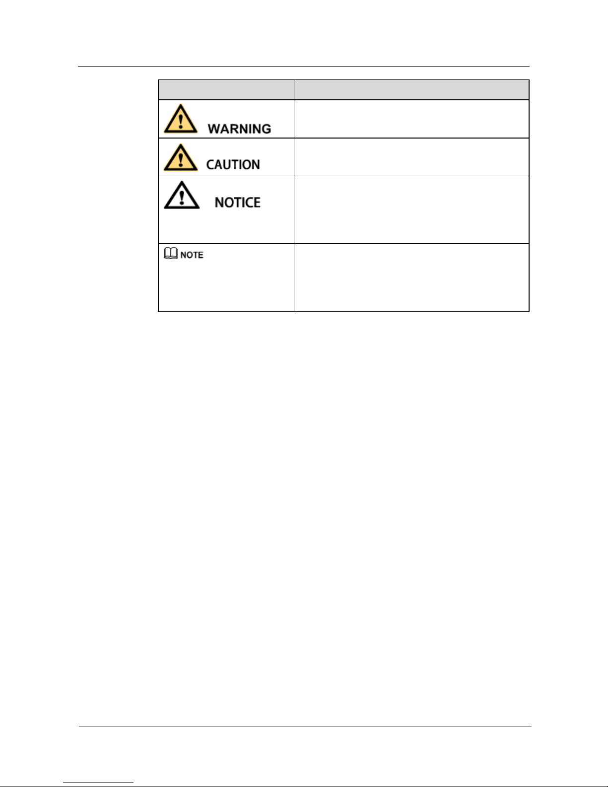
Symbol
Description
Indicates a potentially hazardous situation which, if not
avoided, could result in death or serious injury.
Indicates a potentially hazardous situation which, if not
avoided, may result in minor or moderate injury.
Indicates a potentially hazardous situation which, if not
avoided, could result in equipment damage, data loss,
performance deterioration, or unanticipated results.
NOTICE is used to address practices not related to
personal injury.
Calls attention to important information, best practices
and tips.
NOTE is used to address information not related to
personal injury, equipment damage, and environment
deterioration.
Change History
Changes between document issues are cumulative. The latest document issue contains all the
changes made in previous issues.
Issue 08 (2017-08-04)
Updated the section "Alarm Handling."
Issue 07 (2017-01-19)
Added the DHCP feature.
Added an external dry contact card.
Issue 06 (2016-05-15)
Changed the output wiring terminals of the 3 kVA UPS to a C19 output socket.
Updated the electrical specifications.
Updated the function of the ON/MUTE button.
Added the automatic startup setting.
Updated the display of battery power backup time.
Issue 05 (2016-01-25)
Updated 06: Set the battery capacity and 07: Set the discharge time limit in 4.5 Setting
Parameters.
Added bypass overload capability

UPS2000-G-(1 kVA-3 kVA)
User Manual
About This Document
Issue 08 (2017-08-04)
Huawei Proprietary and Confidential
Copyright © Huawei Technologies Co., Ltd.
iv
Issue 04 (2015-11-23)
Updated settings of the voltage range in ECO mode.
Added button functions for exiting parameter setting screens and alarm screen.
Issue 03 (2015-10-20)
Updated the button description.
Issue 02 (2015-08-29)
Updated the routine maintenance.
Issue 01 (2015-06-25)
This issue is the first official release.

UPS2000-G-(1 kVA-3 kVA)
User Manual
Contents
Issue 08 (2017-08-04)
Huawei Proprietary and Confidential
Copyright © Huawei Technologies Co., Ltd.
v
Contents
About This Document .................................................................................................................... ii
1 Precautions ..................................................................................................................................... 1
1.1 Transportation ............................................................................................................................................................... 1
1.2 Preparation .................................................................................................................................................................... 1
1.3 Operating Environment................................................................................................................................................. 1
1.4 Installation .................................................................................................................................................................... 2
1.5 Operation ...................................................................................................................................................................... 2
1.6 Servicing, Maintenance, and Troubleshooting .............................................................................................................. 3
2 Overview ......................................................................................................................................... 4
2.1 Model Description ........................................................................................................................................................ 4
2.2 Working Principle ......................................................................................................................................................... 5
2.3 Product Structure .......................................................................................................................................................... 6
2.4 Optional Components ................................................................................................................................................... 9
3 Installing the UPS ....................................................................................................................... 12
3.1 Installation Preparations ............................................................................................................................................. 12
3.2 Tools ........................................................................................................................................................................... 13
3.3 Installing UPS ............................................................................................................................................................. 14
3.4 Installing Cables ......................................................................................................................................................... 16
3.5 Installation Verification ............................................................................................................................................... 21
4 Setting Control Panel ................................................................................................................. 23
4.1 LCD Panel .................................................................................................................................................................. 23
4.2 Buzzer Alarm Tones .................................................................................................................................................... 25
4.3 Character Display ....................................................................................................................................................... 26
4.4 Buttons ........................................................................................................................................................................ 27
4.5 Setting Parameters ...................................................................................................................................................... 28
4.6 Operating Modes ........................................................................................................................................................ 35
4.7 Alarm Handing............................................................................................................................................................ 36
4.8 Alarm Indication ......................................................................................................................................................... 47
5 Operations .................................................................................................................................... 48
5.1 Checking Before Powering On the UPS ..................................................................................................................... 48
5.2 Starting the UPS ......................................................................................................................................................... 48

UPS2000-G-(1 kVA-3 kVA)
User Manual
Contents
Issue 08 (2017-08-04)
Huawei Proprietary and Confidential
Copyright © Huawei Technologies Co., Ltd.
vi
5.3 Shutting Down the UPS .............................................................................................................................................. 51
5.4 Transferring to Bypass Mode ...................................................................................................................................... 51
5.5 Transferring from Bypass Mode to Normal Mode ...................................................................................................... 51
5.6 Transferring to Battery Self-check .............................................................................................................................. 51
5.7 Enabling or Disabling the Buzzer ............................................................................................................................... 52
5.8 Manually Clearing Alarms .......................................................................................................................................... 52
5.9 Entering Alarm Cause ID Screen ................................................................................................ ................................ 52
6 Maintenance and Storage .......................................................................................................... 53
6.1 Maintenance ................................................................................................................................................................ 53
6.2 Storage ........................................................................................................................................................................ 53
7 Routine Maintenance ................................................................................................................. 54
7.1 UPS Maintenance ....................................................................................................................................................... 54
7.2 Battery Maintenance ................................................................................................................................................... 55
8 Troubleshooting .......................................................................................................................... 60
9 Specifications ............................................................................................................................... 62
9.1 Physical Specifications ............................................................................................................................................... 62
9.2 Environmental Specifications ..................................................................................................................................... 62
9.3 Mains Input Electrical Specifications ......................................................................................................................... 63
9.4 Bypass Input Electrical Specifications ........................................................................................................................ 64
9.5 Output Electrical Specifications ................................................................................................................................. 64
9.6 Battery Specifications ................................................................................................................................................. 66
9.7 ECO Feature ............................................................................................................................................................... 68
9.8 System Electrical Specifications ................................................................................................................................. 68
9.9 Safety Regulations and EMC ...................................................................................................................................... 69
A Acronyms and Abbreviations .................................................................................................. 70

UPS2000-G-(1 kVA-3 kVA)
User Manual
1 Precautions
Issue 08 (2017-08-04)
Huawei Proprietary and Confidential
Copyright © Huawei Technologies Co., Ltd.
1
1 Precautions
1.1 Transportation
Before transporting the UPS, pack it with original packing materials to protect it from
collision.
1.2 Preparation
The UPS may have condensation inside after it is moved from a cold environment to a
warm environment, such as an indoor environment. In this case, install the UPS after it is
completely dry. Therefore, install the UPS at least 2 hours after it is placed in the target
place.
Never install the UPS in a damp environment or a place with water nearby.
Never install the UPS in a place exposed to sunlight or with a heater nearby.
Never block or shield the air vents on the UPS shell.
1.3 Operating Environment
A UPS can be used to serve resistive-capacitive loads, resistive loads, and
micro-inductive loads. It does not apply to pure capacitive loads, pure inductive loads,
and half-wave rectification loads. It does not apply to energy feedback loads.
Do not place the device in an environment that has inflammable and explosive air or gas. Do
not perform any operation in this kind of environment.
Any operation on any electrical device in an environment that has inflammable air can cause
extreme danger. Strictly obey the operating environmental requirements specified in related
use manuals when using or storing the device.
Donnot places the UPS in the following environments:

UPS2000-G-(1 kVA-3 kVA)
User Manual
1 Precautions
Issue 08 (2017-08-04)
Huawei Proprietary and Confidential
Copyright © Huawei Technologies Co., Ltd.
2
Places where the temperature and humidity are beyond the range of 0–40°C and
0%–95% RH respectively
Indoor environments in which the ambient temperature and humidity are not controlled
or common outdoor environments (including those with simple shelters such as awnings,
and where the humidity can reach 100%)
Places in direct sunlight or near heat sources
Places subject to vibrations or shocks
Dusty places, or places exposed to corrosive substances, salts, or flammable gases
Outdoor land environments (with simple shielding measures) near pollution sources. If a
site is near a pollution source, it is at most:
− 3.7 km away from saline water areas such as the ocean and salinas
− 3 km away from serious pollution sources, such as metallurgic plants, coal mines,
and heat and power plants
− 2 km away from secondary pollution sources, such as chemical factories, rubber
plants, and electroplating factories
− 1 km away from light pollution sources, such as food factories, tanneries, and
heating boilers
1.4 Installation
Never connect a device that will overload the UPS, such as a laser printer, to the output
socket of the UPS.
When routing cables, keep them away from the place where they are easily to be stepped
on or make someone stumble.
Never connect household appliances, such as a hair drier, to the output socket of the
UPS.
The power to the UPS must come from a near grounded cushion socket.
Use only power cables that comply with Verband Deutscher Electrotechniker (VDE) test
standards and Conformité Européenne (CE) certification to connect the UPS to the
indoor cushion socket. The power cable can be the main power cable for your PC.
Use only power cables that comply with VDE test standards and CE certification to
connect a load to the UPS.
When installing the UPS, ensure that the total leakage current of the UPS and connected
loads does not exceed 3.5 mA. The recommended upstream earth leakage circuit breaker
(ELCB) is more than 30 mA.
1.5 Operation
Never disconnect the main power cable for the UPS or use the indoor cushion socket
when the UPS is running. Otherwise, the grounding for the UPS and connected loads
will become invalid.
Since the UPS contains embedded batteries, its output sockets and output terminals are
energized even if the UPS is not connected to a socket.
To completely disconnect the UPS, shut down the UPS and then unplug the power cable.
Prevent liquid or any other foreign objects entering the UPS.

UPS2000-G-(1 kVA-3 kVA)
User Manual
1 Precautions
Issue 08 (2017-08-04)
Huawei Proprietary and Confidential
Copyright © Huawei Technologies Co., Ltd.
3
1.6 Servicing, Maintenance, and Troubleshooting
UPS2000-G-(1 kVA-3 kVA)
User Manual
2 Overview
Issue 08 (2017-08-04)
Huawei Proprietary and Confidential
Copyright © Huawei Technologies Co., Ltd.
4
2 Overview
2.1 Model Description
This document discusses the following UPS models, as shown in Table 2-1.
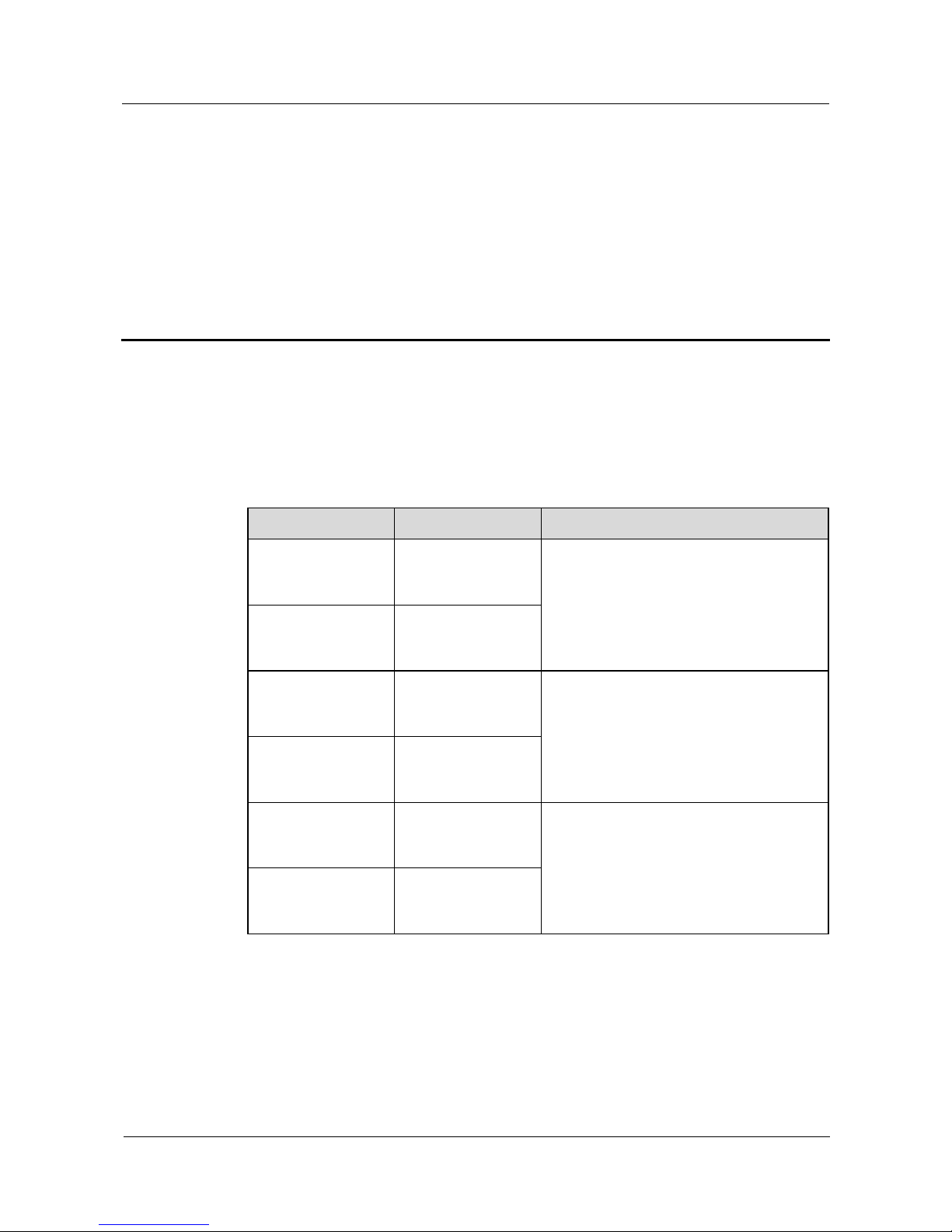
Table 2-1 UPS models
Model
Represented By
Remarks
UPS2000-G-1KRTS
1 K-standard
model-rack
mounted-IEC
The two models are represented by 1 kVA
in the description of their common features
and parameters.
UPS2000-G-1KRTL
1 K-long backup
time model-rack
mounted-IEC
UPS2000-G-2KRTS
2 K-standard
model-rack
mounted-IEC
The two models are represented by 2 kVA
in the description of their common features
and parameters.
UPS2000-G-2KRTL
2 K-long backup
time model-rack
mounted-IEC
UPS2000-G-3KRTS
3 K-standard
model-rack
mounted-IEC
The two models are represented by 3 kVA
in the description of their common features
and parameters.
UPS2000-G-3KRTL
3 K-long backup
time model-rack
mounted-IEC
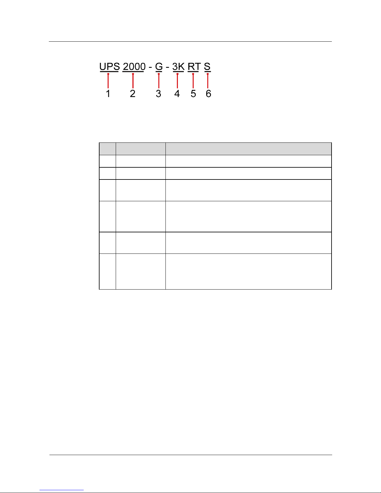
Figure 2-1 shows the UPS model number.
UPS2000-G-(1 kVA-3 kVA)
User Manual
2 Overview
Issue 08 (2017-08-04)
Huawei Proprietary and Confidential
Copyright © Huawei Technologies Co., Ltd.
5
Figure 2-1 UPS model number
Table 2-2 describes the UPS model number.
Table 2-2 UPS model number details
No.
Item
Description
1
Product category
UPS
2
Product family
2000: P (capacity) ≤ 20 kVA
3
Product series
A: tower series
G: rack series
4
Output capacity
Unit: VA
1K: 1 kVA
2K: 2 kVA
3K: 3 kVA
5
UPS type
RT: rack- or tower-mounted UPS
TT: tower-mounted UPS
6
Built-in battery
pack (optional)
S: standard backup time model, which provides only a
standard battery pack
L: long backup time model. You need to use an external
large-capacity battery pack
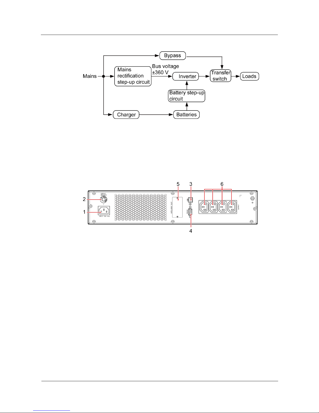
2.2 Working Principle
Figure 2-2 shows the UPS conceptual diagram.
UPS2000-G-(1 kVA-3 kVA)
User Manual
2 Overview
Issue 08 (2017-08-04)
Huawei Proprietary and Confidential
Copyright © Huawei Technologies Co., Ltd.
6
Figure 2-2 UPS conceptual diagram
2.3 Product Structure
Figure 2-3 to Figure 2-8 show the rear view of the 1 kVA, 2 kVA, and 3 kVA UPSs.
Figure 2-3 Rear view of UPS2000-G-1KRTS
(1) Mains input socket (C14)
(2) Input circuit breaker
(3) Universal serial bus (USB) port (security
protection mechanism supported)
(4) RS232 port
(5) Optional card slot
(6) Output socket (C13)
UPS2000-G-(1 kVA-3 kVA)
User Manual
2 Overview
Issue 08 (2017-08-04)
Huawei Proprietary and Confidential
Copyright © Huawei Technologies Co., Ltd.
7
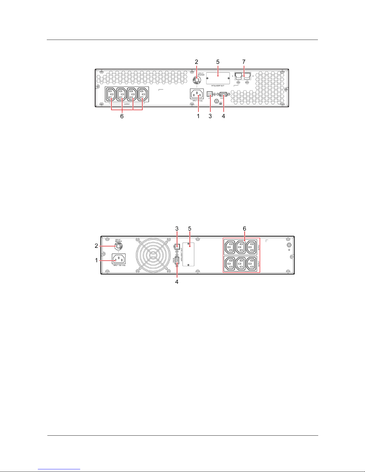
Figure 2-4 Rear view of UPS2000-G-1KRTL
(1) Mains input socket (C14)
(2) Input circuit breaker
(3) USB port (security protection mechanism
supported)
(4) RS232 port
(5) Optional card slot
(6) Output socket (C13)
(7) External battery connector (only for long
backup time models)
Figure 2-5 Rear view of UPS2000-G-2KRTS
(1) Mains input socket (C14)
(2) Input circuit breaker
(3) USB port (security protection
mechanism supported)
(4) RS232 port
(5) Optional card slot
(6) Output socket (C13)

UPS2000-G-(1 kVA-3 kVA)
User Manual
2 Overview
Issue 08 (2017-08-04)
Huawei Proprietary and Confidential
Copyright © Huawei Technologies Co., Ltd.
8
Figure 2-6 Rear view of UPS2000-G-2KRTL
(1) Mains input socket (C14)
(2) Input circuit breaker
(3) USB port (security protection mechanism
supported)
(4) RS232 port
(5) Optional card slot
(6) Output socket (C13)
(7) External battery connector (only for long
backup time models)
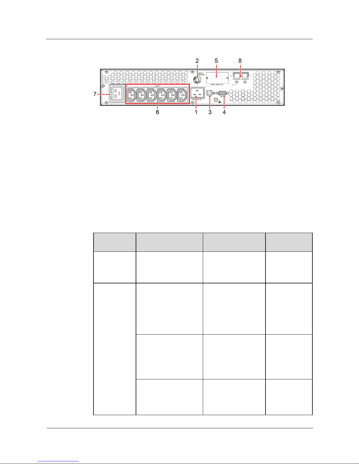
Figure 2-7 Rear view of UPS2000-G-3KRTS
(1) Mains input socket (C20)
(2) Input circuit breaker
(3) USB port (security protection
mechanism supported)
(4) RS232 port
(5) Optional card slot
(6) Output socket (C13)
(7) Output socket (C19)
UPS2000-G-(1 kVA-3 kVA)
User Manual
2 Overview
Issue 08 (2017-08-04)
Huawei Proprietary and Confidential
Copyright © Huawei Technologies Co., Ltd.
9
Figure 2-8 Rear view of UPS2000-G-3KRTL
(1) Mains input socket (C20)
(2) Input circuit breaker
(3) USB port (security protection
mechanism supported)
(4) RS232 port
(5) Optional card slot
(6) Output socket (C13)
(7) Output socket (C19)
(8) External battery connector (only for long
backup time models)
2.4 Optional Components
Optional
Component
Model
Function
Remarks
Ambient
temperature
and humidity
sensor
ENR1DETA MODULE
Measures the UPS
ambient temperature
(0–50°C) and humidity
(0%–100% RH).
Used together
with an SNMP
card.
Battery pack
ESS-36V12-9*2AHBPV
BB01
Contains two battery
strings. Each string
contains three 9 Ah/12
V DC batteries. The
output voltage of the
battery pack is 36 V
DC.
Applicable to the
1 kVA UPS with
long backup
time.
ESS-72V12-9AHBPVBB
01
Contains one battery
string with six 9 Ah/12
V DC batteries. The
output voltage of the
battery pack is 72 V
DC.
Applicable to the
2 kVA UPS with
long backup
time.
ESS-96V12-9AHBPVBB
02
Contains one battery
string with eight 9
Ah/12 V DC batteries.
The output voltage of
the battery pack is 96 V
Applicable to the
3 kVA UPS with
long backup
time.

UPS2000-G-(1 kVA-3 kVA)
User Manual
2 Overview
Issue 08 (2017-08-04)
Huawei Proprietary and Confidential
Copyright © Huawei Technologies Co., Ltd.
10
Optional
Component
Model
Function
Remarks
DC.
SNMP card
RMS-SNMP01B
Monitors the UPS and
provides the Ethernet
networking solution. It
also enables ambient
temperature and
humidity detection.
None
Modbus card
RMS-MODBUS01B
Provides two cascaded
RJ45 ports to
implement networking
over the Modbus or
YDN-23 protocol.
None
Dry contact
card
RMS-RELAY01B
Provides dry contact
signals and manages the
UPS remotely.
None
External dry
contact card
RMS-RELAY02B
Provides dry contact
signals and monitors the
UPS remotely.
Used together
with an SNMP
card.
External
charger
CHG-36V15A-01B
Connects the battery
pack or rack to the
mains and charges the
batteries or battery
pack.
Applicable to the
1 kVA UPS with
long backup
time.
CHG-72V12A-01B
Applicable to the
2 kVA UPS with
long backup
time.
CHG-96V10A-01B
Applicable to the
3 kVA UPS with
long backup
time.
High-voltage
protector
OVCD-230V16A-01B
The OVCD is
connected between the
mains and the UPS
input. If the mains
voltage is abnormally
high, the OVCD
actively disconnects the
L wire between the
mains input and UPS to
prevent the abnormally
high voltage from
flowing into the UPS
and damaging the UPS.
In addition, the OVCD
provides extra input
surge voltage absorbing
None

UPS2000-G-(1 kVA-3 kVA)
User Manual
2 Overview
Issue 08 (2017-08-04)
Huawei Proprietary and Confidential
Copyright © Huawei Technologies Co., Ltd.
11
Optional
Component
Model
Function
Remarks
capability and input
filtering capability.
Guide rail
component
None
Secures the UPS or
battery pack.
Configured in
rack-mounted
scenarios.

UPS2000-G-(1 kVA-3 kVA)
User Manual
3 Installing the UPS
Issue 08 (2017-08-04)
Huawei Proprietary and Confidential
Copyright © Huawei Technologies Co., Ltd.
12
3 Installing the UPS
3.1 Installation Preparations
Floor Loading Capacity
The floor can bear the weight of the UPS and its optional components. In the case of rack
installation, ensure that the floor can also bear the weight of the rack.
For the UPS weight, see chapter 9 Specifications.
Installation Requirements
Do not install the UPS in high temperature, low temperature, and damp areas. For details
about environmental specifications, see chapter 9 Specifications.
The installation position is far away from water sources, heat sources, and inflammable
materials. The UPS is free from direct sunlight, dust, volatile gases, corrosive materials,
and salty air.
Do not install the UPS in environments with conductive metal scraps in the air.
The optimal operating temperatures for batteries are 20–30°C. Operating temperatures
higher than 30°C shorten the battery lifespan, and operating temperatures lower than
20°C reduce the battery backup time.
Dimensions
The space allocated for UPS installation has the combined dimensions of the UPS and its
input and output socket installed on the rear panel. The depth of the space is the depth of
the UPS plus about 100 mm.
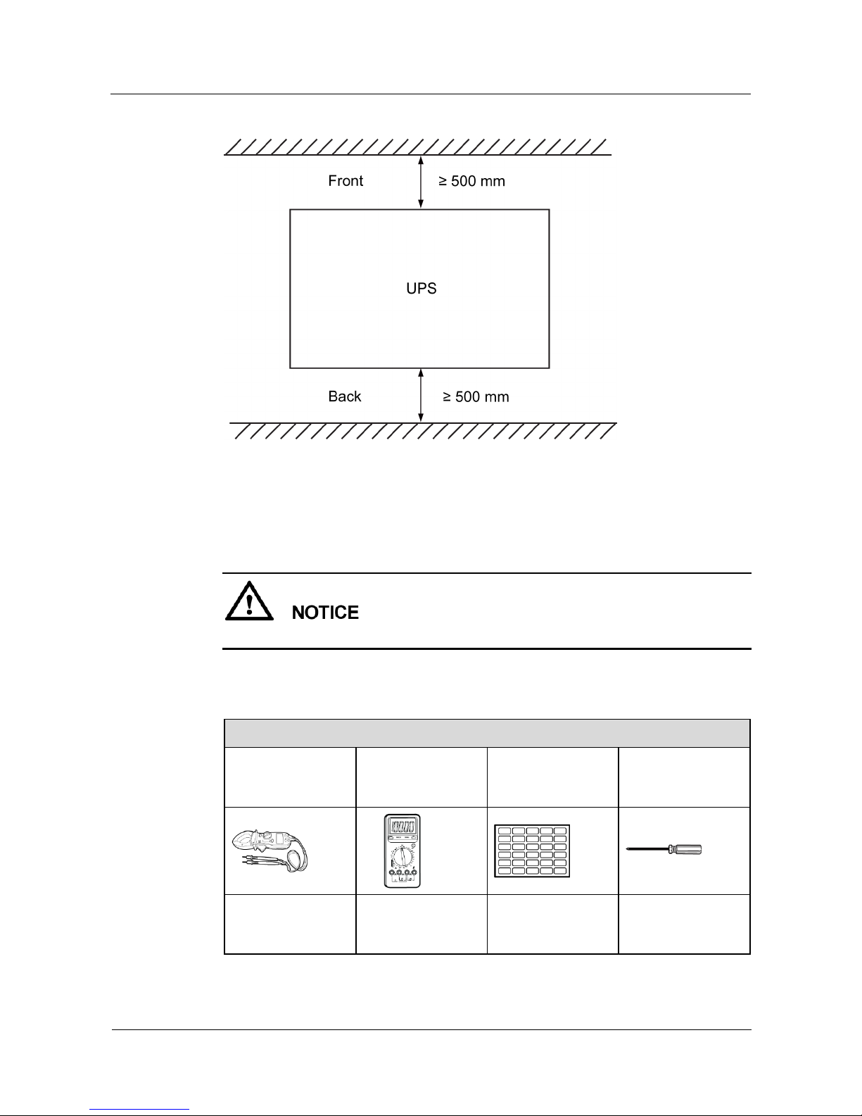
Reserve a clearance of at least 500 mm respectively from the front and rear panels of the
UPS to the wall or adjacent equipment to facilitate ventilation and heat dissipation, as
shown in Figure 3-1.
UPS2000-G-(1 kVA-3 kVA)
User Manual
3 Installing the UPS
Issue 08 (2017-08-04)
Huawei Proprietary and Confidential
Copyright © Huawei Technologies Co., Ltd.
13
Figure 3-1 Reserved clearances
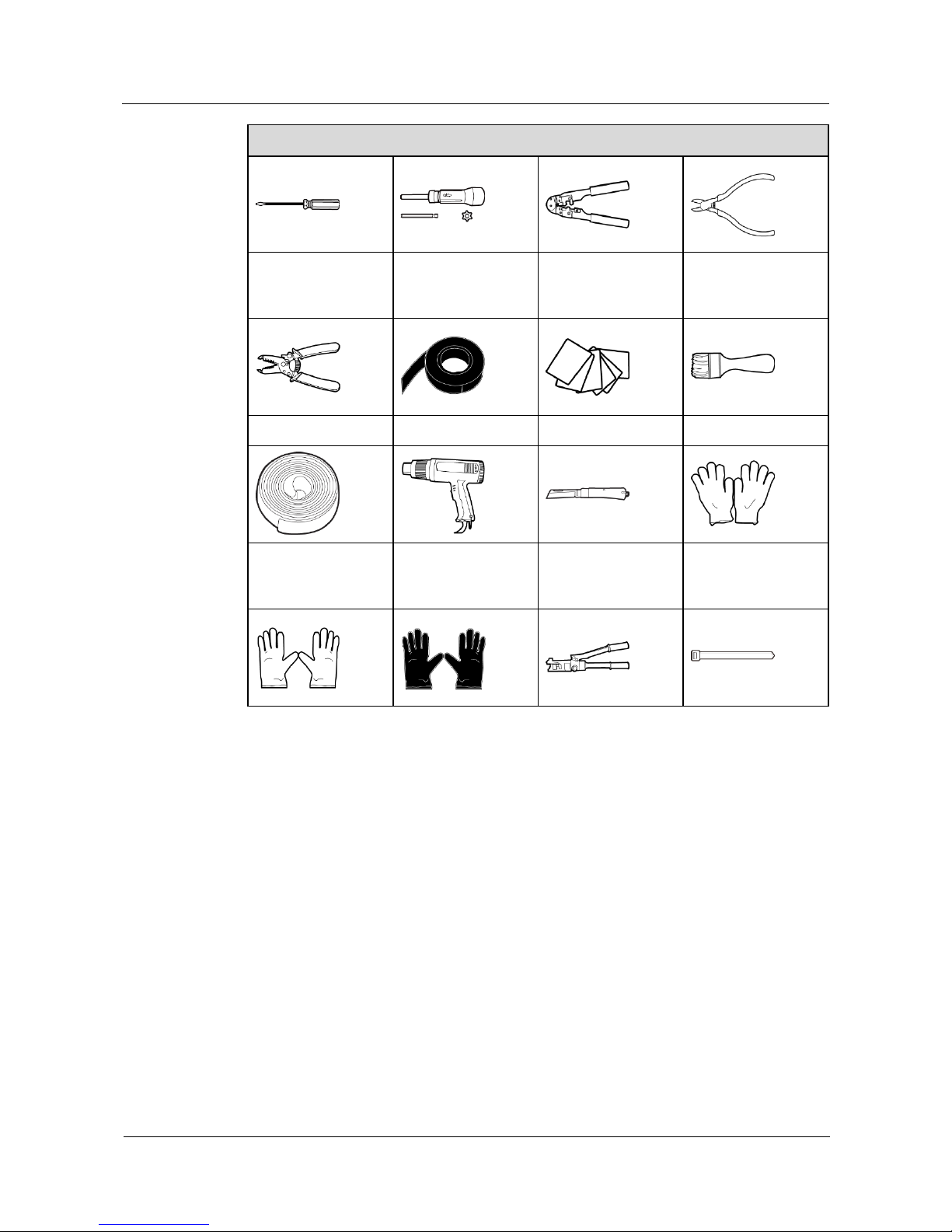
3.2 Tools
Get tools insulated to prevent electric shocks.
Table 3-1 lists the tools that may be used during installation.
Table 3-1 Tools
Appearance, Specifications, and Name
Clamp meter
Multimeter
Labels
Phillips screwdriver
(PH2 x 150 mm or
PH3 x 250 mm)
Flat-head
screwdriver (2 mm x
80 mm)
Torque screwdriver
Crimping tool
Diagonal pliers
UPS2000-G-(1 kVA-3 kVA)
User Manual
3 Installing the UPS
Issue 08 (2017-08-04)
Huawei Proprietary and Confidential
Copyright © Huawei Technologies Co., Ltd.
14
Appearance, Specifications, and Name
Wire stripper
Polyvinyl chloride
(PVC) insulation
tape
Cotton cloth
Brush
Heat shrink tubing
Heat gun
Electrician's knife
Protective gloves
Electrostatic
discharge (ESD)
gloves
Insulation gloves
Hydraulic pliers
Cable tie
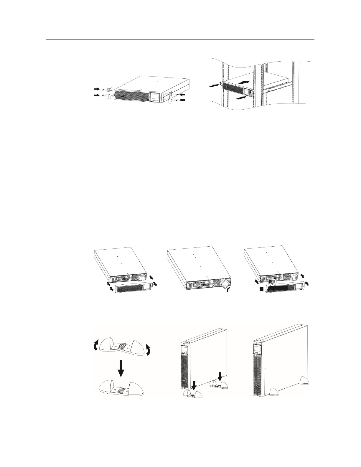
3.3 Installing UPS
The UPS can be installed on a desk or in a 19-inch rack. 1 kVA UPS, 2 kVA UPS, and 3 kVA
UPS need 2 U space separately. The installation method for 1 kVA UPS, 2 kVA UPS and 3
kVA UPS are the same. The figures in this chapter based on the 3 kVA UPS. Install the UPS in
appropriate mode by performing the following steps.
Rack-mounting a UPS
Step 1 Take out mounting brackets from the fitting bag, and install mounting brackets on UPS.
Step 2 Install guide (2 U) on the Cabinet. Then Place the UPS on the guide rails. For details about
how to install guide and UPS on the cabinet, see the UPS2000-G-(1 kVA-3 kVA) Rail
Assembly Quick Installation Guide.
UPS2000-G-(1 kVA-3 kVA)
User Manual
3 Installing the UPS
Issue 08 (2017-08-04)
Huawei Proprietary and Confidential
Copyright © Huawei Technologies Co., Ltd.
15
Figure 3-2 Rack-mounting the UPS
----End
Tower-mounting a UPS
Step 1 Remove the UPS front panel.
Step 2 Rotate the control panel 90 degrees clockwise.
Step 3 Rotate the logo 90 degrees clockwise on the front panel. Reinstall the front panel.
Step 4 Assemble support bases. The minimum distance between two support bases should be 150
mm.
Step 5 Place UPS on the support bases in sequence.
Step 6 Adjust the UPS and the support bases to be horizontally.
Figure 3-3 Tower-mounting the UPS
Figure 3-4 Tower-mounting the UPS
UPS2000-G-(1 kVA-3 kVA)
User Manual
3 Installing the UPS
Issue 08 (2017-08-04)
Huawei Proprietary and Confidential
Copyright © Huawei Technologies Co., Ltd.
16
----End
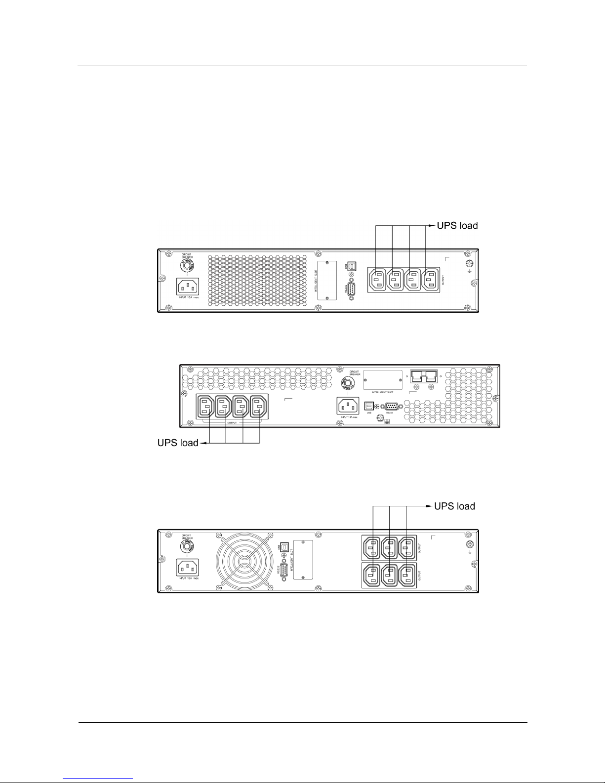
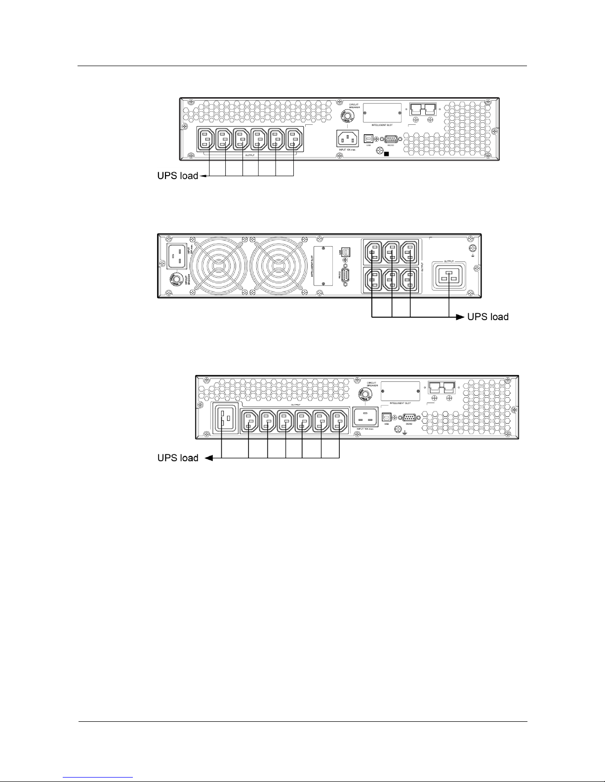
3.4 Installing Cables
Step 1 Connect the UPS output power cable.
For socket-type output, connect loads to the UPS output sockets. When a power failure occurs,
the UPS automatically supplies power to the loads.
Figure 3-5 Connecting cables to the 1KRTS UPS output
Figure 3-6 Connecting cables to the 1KRTL UPS output
Figure 3-7 Connecting cables to the 2KRTS UPS output
UPS2000-G-(1 kVA-3 kVA)
User Manual
3 Installing the UPS
Issue 08 (2017-08-04)
Huawei Proprietary and Confidential
Copyright © Huawei Technologies Co., Ltd.
17
Figure 3-8 Connecting cables to the 2KRTL UPS output
Figure 3-9 Connecting cables to the 3KRTS UPS output
Figure 3-10 Connecting cables to the 3KRTL UPS output
Step 2 Connecting battery power cables to a long backup time model. (The step is optional for long
backup time model, the standard model with built-in batteries cannot support external
batteries.)
For details about battery pack installation, see the UPS2000-G-(1 kVA-3 kVA) Battery Pack
Quick Installation Guide.
The installation method for 1 kVA UPS, 2 kVA UPS, and 3 kVA UPS are the same. The
figures below are based on the 3 kVA UPS.
 Loading...