

Page 1
SUN2000L-(2KTL-5KTL)
User Manual
Issue
02
Date
2017-12-12
HUAWEI TECHNOLOGIES CO., LTD.
Page 2

Issue 02 (2017-12-12)
Huawei Proprietary and Confidential
Copyright © Huawei Technologies Co., Ltd.
i
Copyright © Huawei Technologies Co., Ltd. 2017. All rights reserved.
No part of this document may be reproduced or transmitted in any form or by any means without prior
written consent of Huawei Technologies Co., Ltd.
Trademarks and Permissions
and other Huawei trademarks are trademarks of Huawei Technologies Co., Ltd.
All other trademarks and trade names mentioned in this document are the property of their respective
holders.
Notice
The purchased products, services and features are stipulated by the contract made between Huawei and
the customer. All or part of the products, services and features described in this document may not be
within the purchase scope or the usage scope. Unless otherwise specified in the contract, all statements,
information, and recommendations in this document are provided "AS IS" without warranties, guarantees or
representations of any kind, either express or implied.
The information in this document is subject to change without notice. Every effort has been made in the
preparation of this document to ensure accuracy of the contents, but all statements, information, and
recommendations in this document do not constitute a warranty of any kind, express or implied.
Huawei Technologies Co., Ltd.
Address:
Huawei Industrial Base
Bantian, Longgang
Shenzhen 518129
People's Republic of China
Website:
http://www.huawei.com
Email:
Page 3
SUN2000L-(2KTL-5KTL)
User Manual
About This Document
Issue 02 (2017-12-12)
Huawei Proprietary and Confidential
Copyright © Huawei Technologies Co., Ltd.
ii
About This Document
Purpose
This document describes the SUN2000L-(2KTL-5KTL) in terms of its installation, electrical
connections, commissioning, maintenance, and troubleshooting. SUN2000L-(2KTL-5KTL) is
abbreviated as SUN2000L. Before installing and operating the SUN2000L, ensure that you
are familiar with the features, functions, and safety precautions provided in this document.
Intended Audience
This document is intended for:
Installers
Users
Symbol Conventions
The symbols that may be found in this document are defined as follows.
Symbol
Description
Indicates an imminently hazardous situation which, if not
avoided, will result in serious injury or death.
Indicates a potentially hazardous situation which, if not
avoided, could result in serious injury or death.
Indicates a potentially hazardous situation which, if not
avoided, may result in minor or moderate injury.
Indicates a potentially hazardous situation which, if not
avoided, could result in equipment damage, data loss,
performance deterioration, or unanticipated results.
NOTICE is used to address practices not related to personal
injury.
Page 4
SUN2000L-(2KTL-5KTL)
User Manual
About This Document
Issue 02 (2017-12-12)
Huawei Proprietary and Confidential
Copyright © Huawei Technologies Co., Ltd.
iii
Symbol
Description
Calls attention to important information, best practices and
tips.
NOTE is used to address information not related to personal
injury, equipment damage, or environment deterioration.
Change History
Changes between document issues are cumulative. The latest document issue contains all
updates made in previous issues.
Issue 02 (2017-12-12)
Updated the networking application diagram.
Updated the battery power-on sequence.
Upgraded the FusionHome app to 2.1.11.201.
Issue 01 (2017-09-27)
This issue is used for first office application (FOA).
Page 5

SUN2000L-(2KTL-5KTL)
User Manual
Contents
Issue 02 (2017-12-12)
Huawei Proprietary and Confidential
Copyright © Huawei Technologies Co., Ltd.
iv
Contents
About This Document .................................................................................................................... ii
1 Safety Precautions ......................................................................................................................... 1
2 Product Overview ......................................................................................................................... 5
2.1 Product Introduction ..................................................................................................................................................... 5
2.2 Appearance ................................................................................................................................................................... 7
2.3 Label Description ........................................................................................................................................................ 11
2.4 Working Principles...................................................................................................................................................... 14
3 Storage ........................................................................................................................................... 17
4 System Installation ..................................................................................................................... 18
4.1 Checking Before Installation ...................................................................................................................................... 18
4.2 Tools and Instruments ................................................................................................................................................. 19
4.3 Determining the Installation Position ......................................................................................................................... 20
4.4 Installing the Mounting Bracket ................................................................................................................................. 24
4.4.1 Wall-Mounted Installation ....................................................................................................................................... 25
4.4.2 Support-mounted Installation .................................................................................................................................. 27
4.5 Installing the SUN2000L ............................................................................................................................................ 29
4.6 Installing the WiFi Antenna ........................................................................................................................................ 33
5 Electrical Connections ................................................................................................................ 34
5.1 Preparing Cables ......................................................................................................................................................... 35
5.2 Installing the PE Cable ............................................................................................................................................... 38
5.3 Installing the AC Output Power Cable ........................................................................................................................ 39
5.4 Installing the DC Input Power Cable .......................................................................................................................... 44
5.5 Installing the Battery Cable ........................................................................................................................................ 49
5.6 Installing the Signal Cable .......................................................................................................................................... 51
6 System Commissioning ............................................................................................................. 56
6.1 Checking Before Power-On ........................................................................................................................................ 56
6.2 Powering On the System............................................................................................................................................. 57
6.3 Powering Off the System ............................................................................................................................................ 59
7 Operations on the Local FusionHome App ........................................................................... 60
7.1 App Overview ............................................................................................................................................................. 60
Page 6

SUN2000L-(2KTL-5KTL)
User Manual
Contents
Issue 02 (2017-12-12)
Huawei Proprietary and Confidential
Copyright © Huawei Technologies Co., Ltd.
v
7.2 Downloading and Installing the App .......................................................................................................................... 62
7.3 Connecting to a SUN2000L WiFi Network ................................................................................................................ 62
7.4 App Operations by the Installer .................................................................................................................................. 66
7.4.1 Logging In to the App .............................................................................................................................................. 66
7.4.2 Querying the SUN2000L Information ..................................................................................................................... 69
7.4.3 Maintaining the SUN2000L ..................................................................................................................................... 72
7.4.3.1 Adding/Deleting Devices ...................................................................................................................................... 73
7.4.3.2 Upgrading the Device ........................................................................................................................................... 74
7.4.3.3 Energy Control ...................................................................................................................................................... 76
7.4.3.3.1 Grid-tied Point Control ...................................................................................................................................... 77
7.4.3.3.2 Energy Storage Control ...................................................................................................................................... 78
7.4.3.4 IPS Check (Only for Italy CEI0-21 Grid Code).................................................................................................... 81
7.4.3.5 Starting or Shutting Down the SUN2000L ........................................................................................................... 83
7.4.3.6 Restoring Factory Defaults ................................................................................................................................... 84
7.4.3.7 Clearing Data ........................................................................................................................................................ 84
7.4.3.8 Adjusting Total Energy Yield ................................................................................................................................ 85
7.4.3.9 Restarting the SUN2000L ..................................................................................................................................... 86
7.4.4 Quick Setting ........................................................................................................................................................... 87
7.4.5 Setting Grid-Connection Parameters ....................................................................................................................... 90
7.4.5.1 Setting Grid Parameters ................................................................................................................................ ........ 91
7.4.5.2 Setting Protection Parameters ............................................................................................................................... 93
7.4.5.3 Feature Parameters ................................................................................................................................................ 95
7.4.5.4 Adjusting Power .................................................................................................................................................. 101
7.4.5.5 Time setting ........................................................................................................................................................ 103
7.4.6 Comm Config ........................................................................................................................................................ 105
7.4.7 Managing Logs ...................................................................................................................................................... 112
7.4.8 Menu ...................................................................................................................................................................... 113
7.4.8.1 Changing the Password ................................................................................................ ....................................... 113
7.4.8.2 About .................................................................................................................................................................. 114
7.5 App Operations by the User ...................................................................................................................................... 115
7.5.1 Logging In to the App ............................................................................................................................................ 115
7.5.2 Querying the Device Status ................................................................................................................................... 116
7.5.3 Querying Alarms .................................................................................................................................................... 117
7.5.4 Querying Power Curves ......................................................................................................................................... 118
7.5.5 Querying Energy Yields ......................................................................................................................................... 119
7.5.6 Settings .................................................................................................................................................................. 120
7.5.7 About ..................................................................................................................................................................... 123
7.6 Troubleshooting ........................................................................................................................................................ 124
8 System Maintenance................................................................................................................. 125
8.1 Routine Maintenance ................................................................................................................................................ 125
8.2 Troubleshooting ........................................................................................................................................................ 126
Page 7

SUN2000L-(2KTL-5KTL)
User Manual
Contents
Issue 02 (2017-12-12)
Huawei Proprietary and Confidential
Copyright © Huawei Technologies Co., Ltd.
vi
9 Handling the SUN2000L .......................................................................................................... 133
9.1 Removing the SUN2000L ........................................................................................................................................ 133
9.2 Packing the SUN2000L ............................................................................................................................................ 133
9.3 Disposing of the SUN2000L................................................................................................ ..................................... 133
10 Technical Specifications ........................................................................................................ 134
A Grid Codes................................................................................................................................. 138
B Acronyms and Abbreviations ................................................................................................ 143
Page 8
SUN2000L-(2KTL-5KTL)
User Manual
1 Safety Precautions
Issue 02 (2017-12-12)
Huawei Proprietary and Confidential
Copyright © Huawei Technologies Co., Ltd.
1
1 Safety Precautions
General Safety
Before performing operations, read through this manual and follow all the precautions to
prevent accidents. The "DANGER", "WARNING", "CAUTION", and "NOTICE" marks
in this document do not represent all the safety instructions. They are only supplements to
the safety instructions.
Only certified electricians are allowed to install, connect cables for, commission, maintain,
and troubleshoot Huawei products, and they must understand basic safety precautions to
avoid hazards.
When operating Huawei equipment, in addition to following the general precautions in this
document, follow the specific safety instructions given by Huawei. Huawei will not be liable
for any consequence caused by the violation of the safety operation regulations and design,
production, and usage standards.
Disclaimer
Huawei shall not be liable for any consequence caused by any of the following events:
Transportation damage
The storage conditions do not meet the requirements specified in this document.
Incorrect storage, installation, or use
Installation or use by unqualified personnel
Failure to obey the operation instructions and safety precautions in this document
Operation in extreme environments which are not covered in this document
Operation beyond specified ranges.
Unauthorized modifications to the product or software code or removal of the product
Device damage due to force majeure (such as lightning, earthquake, fire, and storm)
The warranty expires and the warranty service is not extended.
Installation or use in environments which are not specified in related international
standards
Page 9

SUN2000L-(2KTL-5KTL)
User Manual
1 Safety Precautions
Issue 02 (2017-12-12)
Huawei Proprietary and Confidential
Copyright © Huawei Technologies Co., Ltd.
2
Personnel Requirements
Only certified electricians are allowed to install, connect cables for, commission, maintain,
troubleshoot, and replace the SUN2000L.
Operation personnel should receive professional training.
Operation personnel should read through this document and follow all the precautions.
Operation personnel should be familiar with the safety specifications about the electrical
system.
Operation personnel should understand the composition and working principles of the
grid-tied PV system and local regulations.
Operation personnel must wear proper personal protective equipment (PPE).
Protect Labels
Do not scrawl or damage any labels on the SUN2000L enclosure because these labels
contain important information about safe operation.
Do not scrawl or damage the nameplate on the SUN2000L enclosure because it contains
important product information.
Installation
Never operate the SUN2000L under power during installation.
Ensure that the SUN2000L is not connected to a power supply or powered on before
finishing installation.
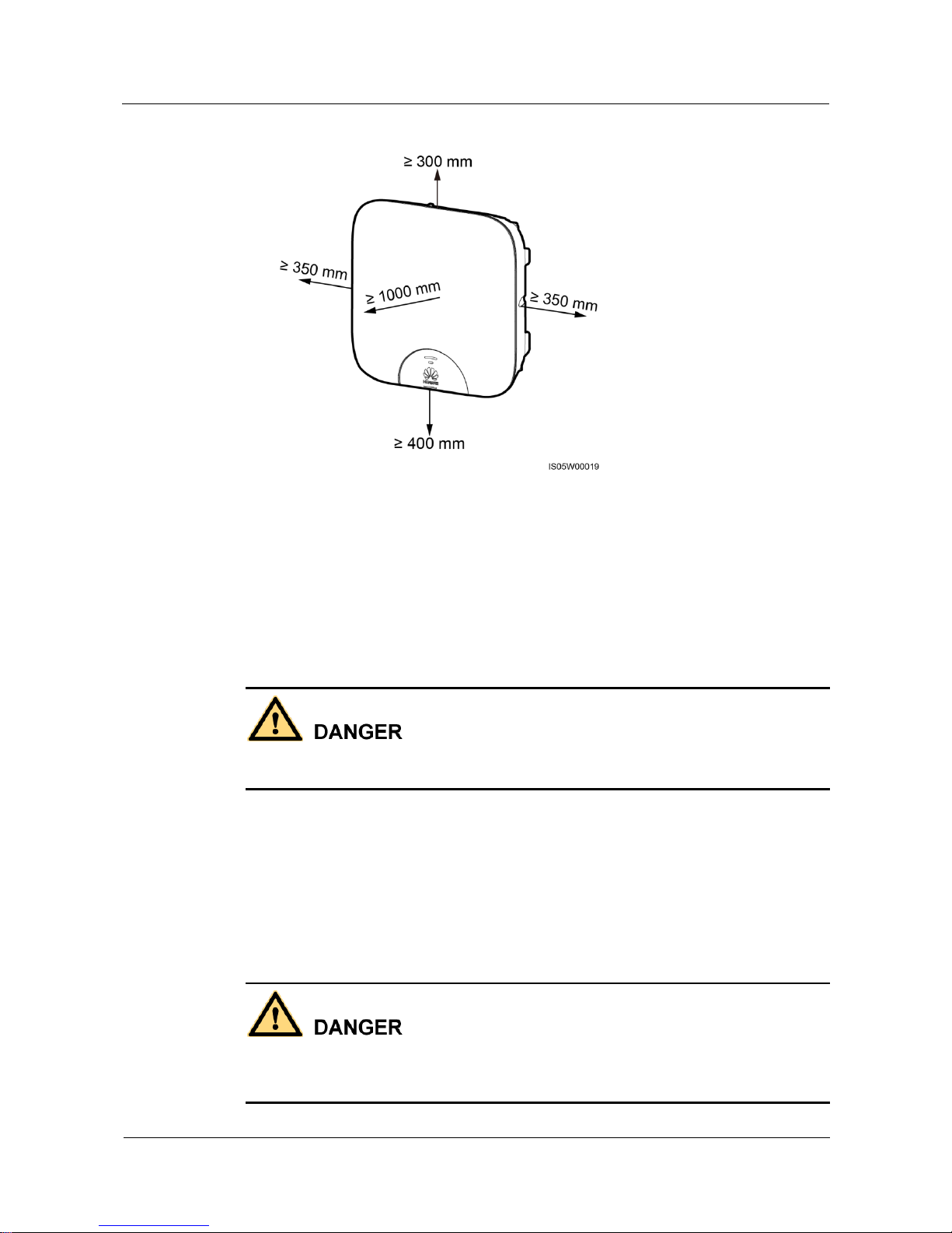
To allow proper heat dissipation and installation, maintain appropriate clearances
between the SUN2000L and other objects, as shown in Figure 1-1. If you have any
questions about the clearances, consult local technical support engineers.
Page 10
SUN2000L-(2KTL-5KTL)
User Manual
1 Safety Precautions
Issue 02 (2017-12-12)
Huawei Proprietary and Confidential
Copyright © Huawei Technologies Co., Ltd.
3
Figure 1-1 Installation space
Ensure that the SUN2000L is installed in a well-ventilated environment.
Ensure that the SUN2000L heat sinks are free from blockage.
Do not open the front panel of the SUN2000L.
Do not remove the terminals and ports at the bottom of the SUN2000L.
Electrical Connections
Before connecting cables, ensure that the SUN2000L is secured in position and not damaged
in any way. Otherwise, electric shocks or fire may occur.
Ensure that all electrical connections comply with local electrical standards.
Obtain approval from the local utility company before using the SUN2000L to generate
electricity in grid-tied mode.
Ensure that the cables used in a grid-tied PV system are properly connected and insulated
and meet all specification requirements.
Operation
High voltage may cause an electric shock, which results in serious injury, death, or serious
property damage from the SUN2000L in operation. Strictly comply with the safety
precautions in this document and associated documents when operating the SUN2000L.
Page 11
SUN2000L-(2KTL-5KTL)
User Manual
1 Safety Precautions
Issue 02 (2017-12-12)
Huawei Proprietary and Confidential
Copyright © Huawei Technologies Co., Ltd.
4
When the SUN2000L is powered on for the first time, only certified electricians are
allowed to perform quick setting. Incorrect settings may affect the normal SUN2000L
operation and cause the SUN2000L to conflict with the country certification.
When the SUN2000L is operating, do not disconnect under load.
Do not touch an energized SUN2000L because the heat sink has a high temperature.
Follow local laws and regulations when operating the equipment.
Maintenance and Replacement
High voltage may cause an electric shock, which results in serious injury, death, or serious
property damage from the SUN2000L in operation. Prior to maintenance, power off the
SUN2000L and strictly comply with the safety precautions in this document and associated
documents to operate the SUN2000L.
Maintain the SUN2000L with sufficient knowledge of this document, proper tools, and
testing equipment.
Before performing maintenance tasks, power off the SUN2000L and wait at least 5
minutes.
Temporary warning signs or fences must be placed to prevent unauthorized people from
entering the site.
If the SUN2000L is faulty, contact your supplier.
The SUN2000L can be powered on only after all faults are rectified. Failing to do so may
escalate faults or damage the device.
Observe ESD precautions and wear ESD gloves during maintenance.
Page 12
SUN2000L-(2KTL-5KTL)
User Manual
2 Product Overview
Issue 02 (2017-12-12)
Huawei Proprietary and Confidential
Copyright © Huawei Technologies Co., Ltd.
5
2 Product Overview
2.1 Product Introduction
Function
The SUN2000L is a single-phase grid-tied PV string inverter that converts the DC power
generated by PV strings into AC power and feeds the electricity into the power grid.
Models
This document involves the following product models:
SUN2000L-2KTL
SUN2000L-3KTL
SUN2000L-3.68KTL
SUN2000L-4KTL
SUN2000L-4.6KTL
SUN2000L-5KTL
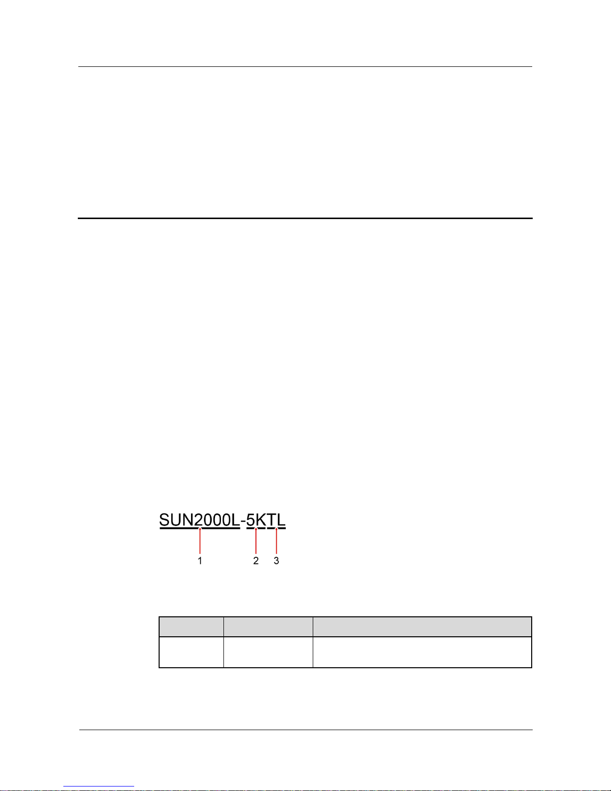
Figure 2-1 Designation explanation of the SUN2000L-5KTL
Table 2-1 Designation explanation of the SUN2000L-5KTL
No.
Meaning
Description
1
Series name
SUN2000L: single-phase grid-tied PV string
inverter
Page 13
SUN2000L-(2KTL-5KTL)
User Manual
2 Product Overview
Issue 02 (2017-12-12)
Huawei Proprietary and Confidential
Copyright © Huawei Technologies Co., Ltd.
6
No.
Meaning
Description
2
Power level
2K: The power level is 2K.
3K: The power level is 3K.
3.68K: The power level is 3.68K.
4K: The power level is 4K.
4.6K: The power level is 4.6K.
5K: The power level is 5K.
3
Topology
TL: transformerless
Networking Application
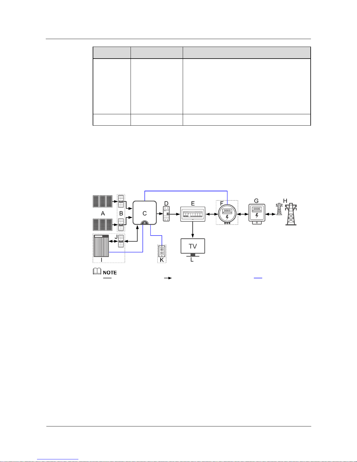
The SUN2000L applies to a residential rooftop grid-tied system. Typically, a grid-tied system
consists of the PV string, grid-tied inverter, AC switch, and power distribution unit.
Figure 2-2 Network diagram (optional in dashed boxes)
indicates a power cable, indicates the power flow direction, and indicates a signal
cable.
(A) PV string
(B) DC switch
(C) SUN2000L
(D) AC switch
(E) Residential power distribution
unit
(F) Energy meter
(G) Residential power
meter
(H) Power grid
(I) Battery
(J) Battery switch
(K) Alarm beacon
(L) Residential
load
Supported Power Grid
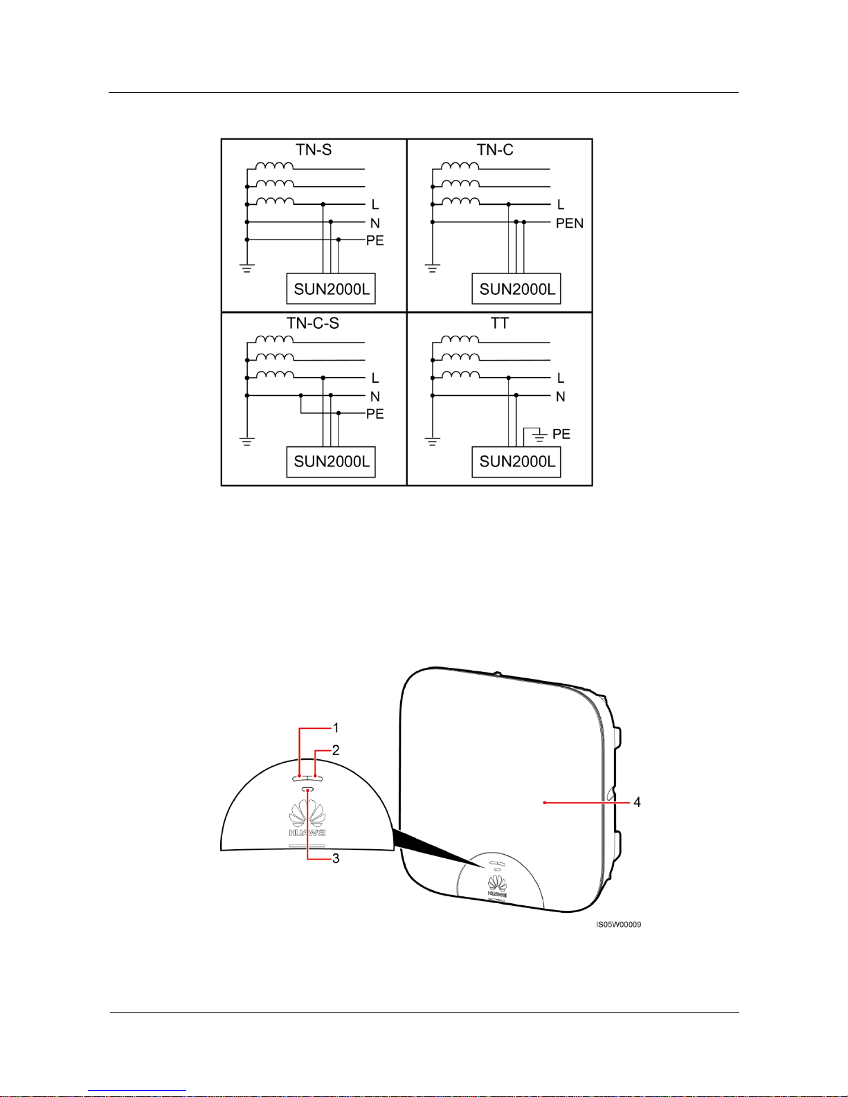
Power grid types supported by the SUN2000L include TN-S, TN-C, TN-C-S, and TT. In a TT
power grid, the N-PE voltage should be lower than 30 V.
Page 14
SUN2000L-(2KTL-5KTL)
User Manual
2 Product Overview
Issue 02 (2017-12-12)
Huawei Proprietary and Confidential
Copyright © Huawei Technologies Co., Ltd.
7
Figure 2-3 Power grid types
2.2 Appearance
Front View
Figure 2-4 Front view
(1) LED 1
(2) LED 2
(3) LED 3
(4) Front panel
Page 15
SUN2000L-(2KTL-5KTL)
User Manual
2 Product Overview
Issue 02 (2017-12-12)
Huawei Proprietary and Confidential
Copyright © Huawei Technologies Co., Ltd.
8
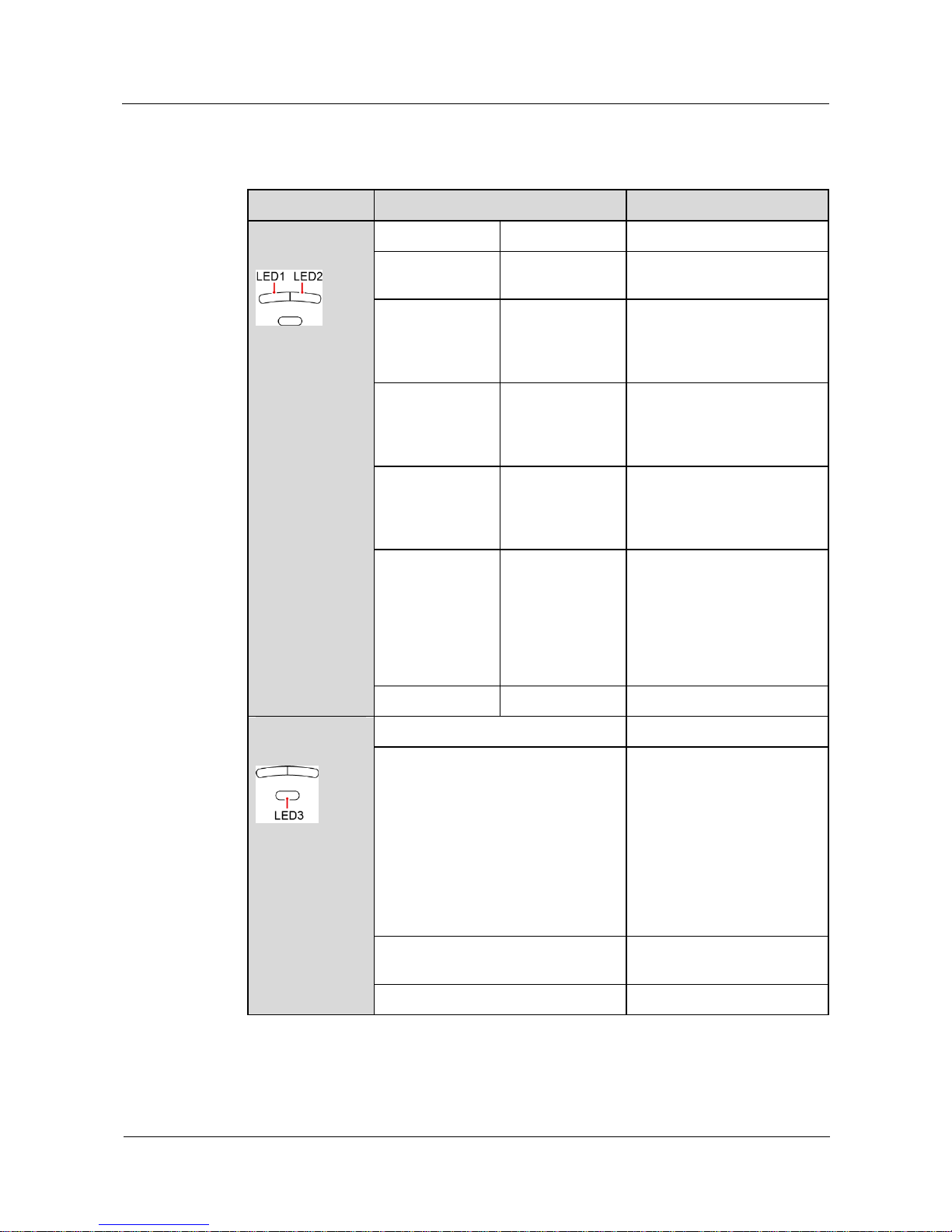
Table 2-2 LED description
Type
Status
Meaning
Running
indication
LED 1
LED 2
N/A
Steady green
Steady green
The SUN2000L is exporting
power to the power grid.
Blinking green at
long intervals (on
for 1s and then
off for 1s)
Off
The DC is on and the AC is
off.
Off
Blinking green at
long intervals (on
for 1s and then
off for 1s)
The DC is off and the AC is
on.
Blinking green at
long intervals (on
for 1s and then
off for 1s)
Blinking green at
long intervals (on
for 1s and then
off for 1s)
The DC is on, the AC is on,
and the SUN2000L is not
exporting power to the power
grid.
Off
Off
Both the DC and AC are off,
or the SUN2000L is in Low
Power Consumption mode.
Low Power Consumption
mode means that the
monitoring system of the
SUN2000L hibernates.
Steady red
Steady red
The SUN2000L is faulty.
Communicatio
n indication
LED 3
N/A
Blinking green at short intervals (on
for 0.2s and then off for 0.2s)
Communicating
(Communicating refers to that
the communication with the
upper-level management unit
is in progress. However, if a
mobile phone accesses the
SUN2000L, the LED
indicates the "mobile phone
access status: blinking green
at long intervals" first.)
Blinking green at long intervals (on
for 1s and then off for 1s)
The mobile phone has
connected to the SUN2000L.
Off
Others
Page 16
SUN2000L-(2KTL-5KTL)
User Manual
2 Product Overview
Issue 02 (2017-12-12)
Huawei Proprietary and Confidential
Copyright © Huawei Technologies Co., Ltd.
9
Rear View
Figure 2-5 Rear view
(1) Mounting plate
(2) Mounting bracket
(3) Heat sink
Bottom View
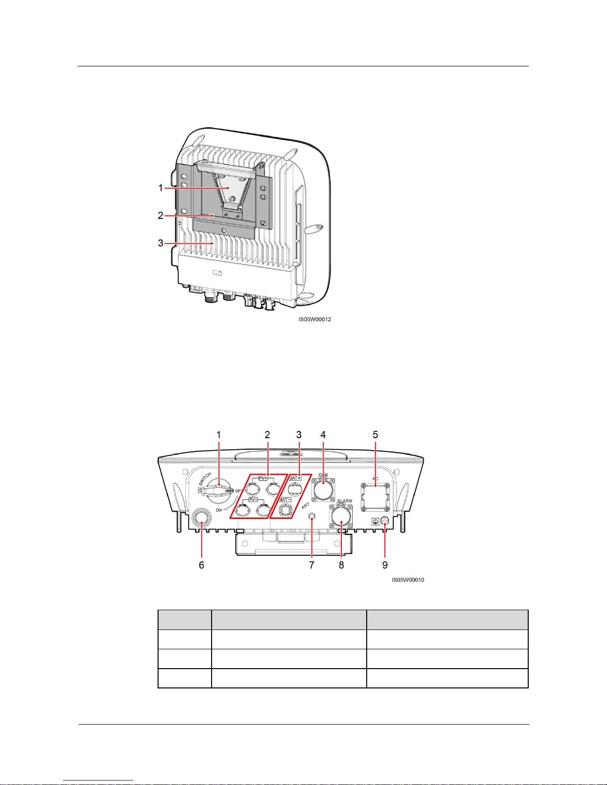
Figure 2-6 Bottom view
No.
Component
Silk Screen
1
DC switch
DC SWITCH
2
DC input terminal
PV+/PV–
3
Battery terminal
BAT+/BAT–
Page 17
SUN2000L-(2KTL-5KTL)
User Manual
2 Product Overview
Issue 02 (2017-12-12)
Huawei Proprietary and Confidential
Copyright © Huawei Technologies Co., Ltd.
10
No.
Component
Silk Screen
4
COM port
COM
5
AC output port
AC
6
Ventilation valve
N/A
7
Antenna port
ANT
8
Alarm port
ALARM
9
Ground point
N/A
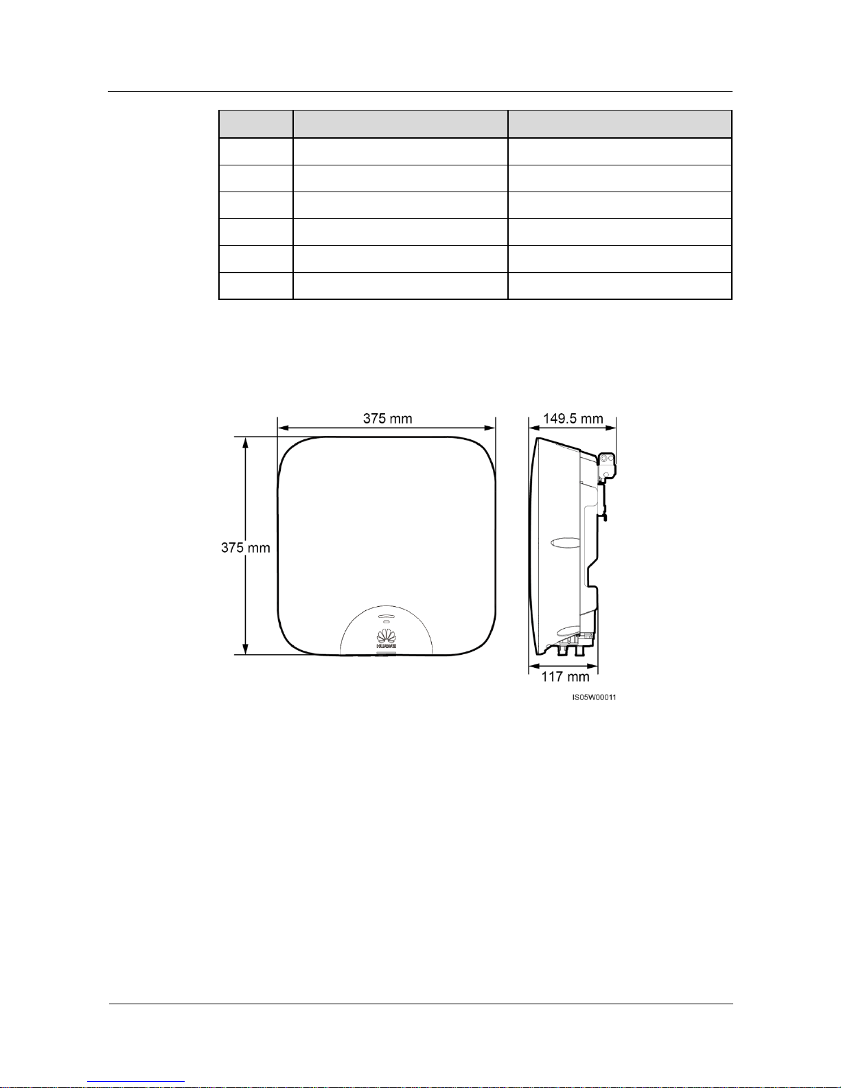
Dimensions
Figure 2-7 Enclosure dimensions
Page 18
SUN2000L-(2KTL-5KTL)
User Manual
2 Product Overview
Issue 02 (2017-12-12)
Huawei Proprietary and Confidential
Copyright © Huawei Technologies Co., Ltd.
11
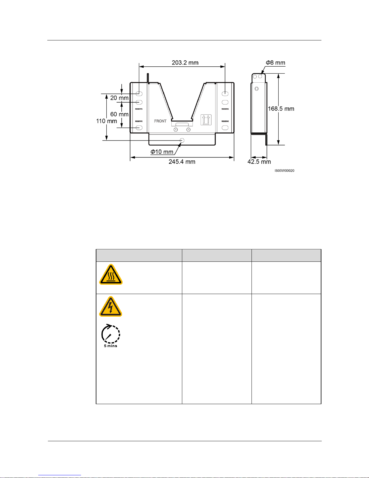
Figure 2-8 Mounting bracket dimensions
2.3 Label Description
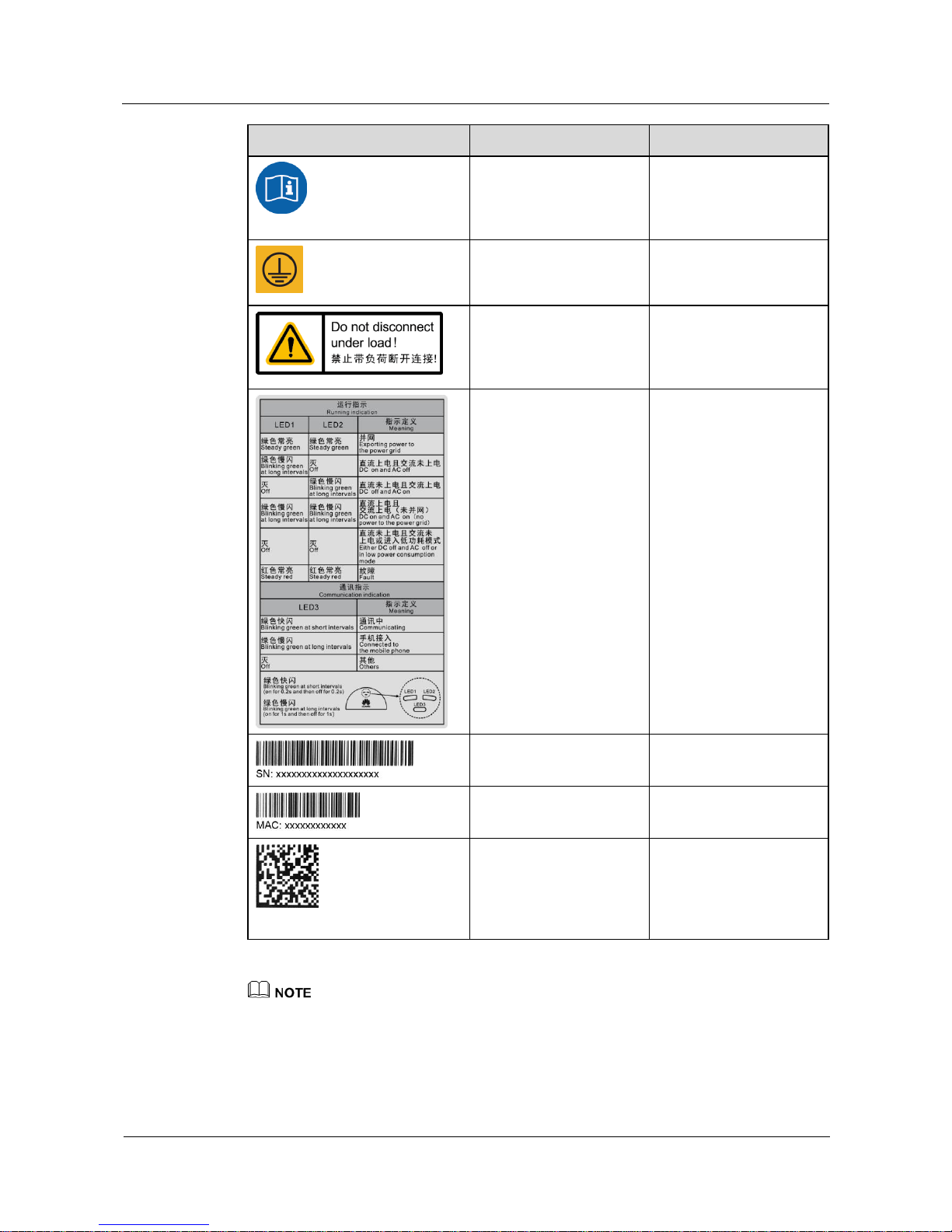
Symbols
Table 2-3 Label description
Symbol
Name
Meaning
Burn warning
Do not touch a running
SUN2000L because the
shell is hot when the
SUN2000L is running.
Delay discharge
High voltage exists
after the SUN2000L is
powered on. Only
qualified and trained
electrical technicians
are allowed to perform
operations on the
SUN2000L.
Residual voltage exists
after the SUN2000L is
powered off. It takes 5
minutes for the
SUN2000L to
discharge to the safe
voltage.
Page 19
SUN2000L-(2KTL-5KTL)
User Manual
2 Product Overview
Issue 02 (2017-12-12)
Huawei Proprietary and Confidential
Copyright © Huawei Technologies Co., Ltd.
12
Symbol
Name
Meaning
Refer to documentation
Reminds operators to
refer to the documents
shipped with the
SUN2000L.
Grounding
Indicates the position for
connecting the protective
earthing (PE) cable.
Operation warning
Do not remove the
connector or antenna
when the SUN2000L is
running.
Indicator status
description label
Describes the indicator
status.
SUN2000L serial number
(SN) label
Indicates the SUN2000L
SN.
SUN2000L MAC address
label
Indicates the MAC
address.
QR code for SUN2000L
WiFi connection
Scan the QR code to
connect to Huawei
SUN2000L WiFi network
(Android) or obtain the
WiFi password (iOS).
The labels are for reference only.
Page 20
SUN2000L-(2KTL-5KTL)
User Manual
2 Product Overview
Issue 02 (2017-12-12)
Huawei Proprietary and Confidential
Copyright © Huawei Technologies Co., Ltd.
13
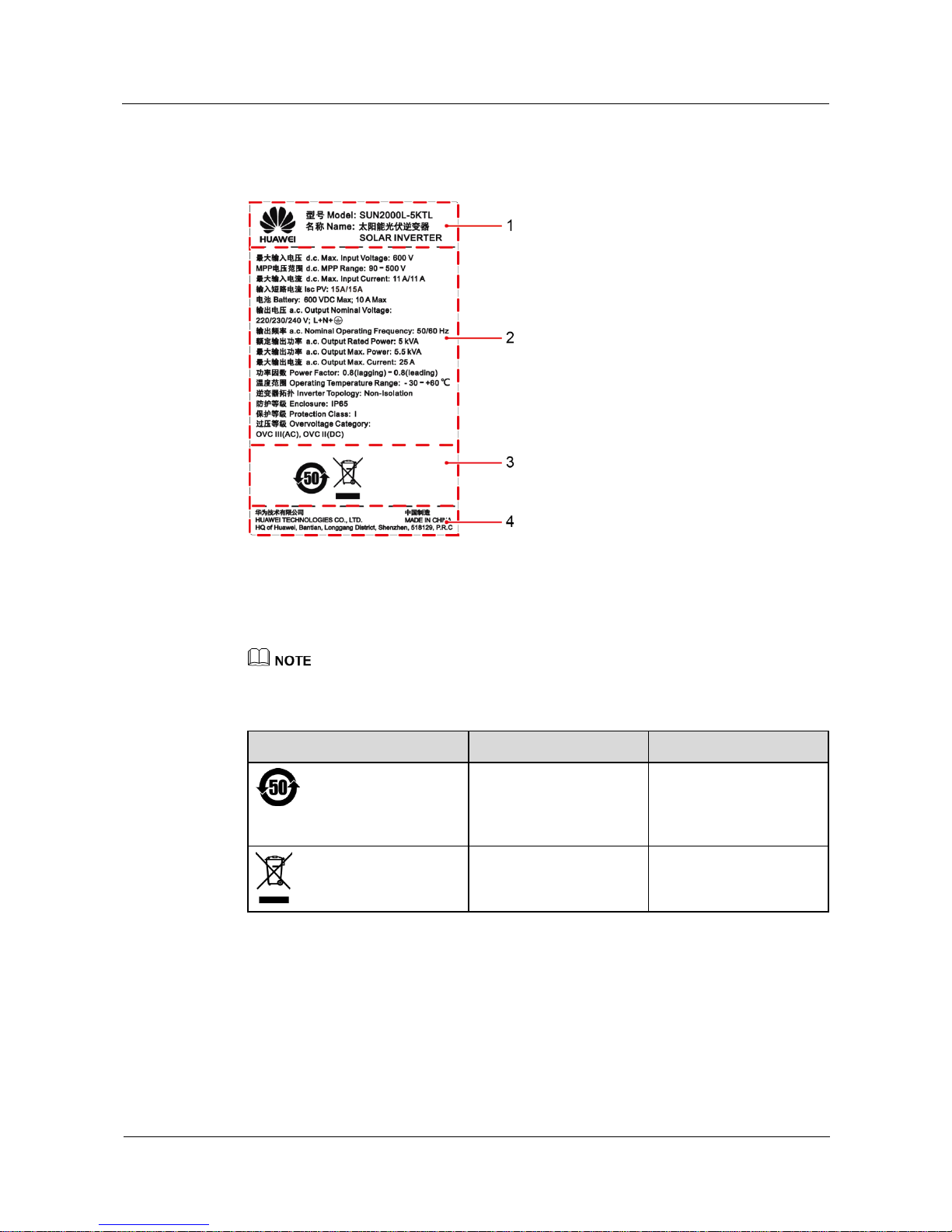
Nameplate
Figure 2-9 Nameplate
(1) Trademark and product model
(2) Important technical specifications
(3) Compliance symbols
(4) Company name and country of manufacture
The nameplate figure is for reference only.
Table 2-4 Compliance symbols
Symbol
Name
Meaning
Environment friendly use
period (EFUP) mark
The product does not
pollute the environment
during the specified
period.
EU waste electrical and
electronic equipment
(WEEE) mark
Do not dispose of the
product as household
garbage.
Page 21
SUN2000L-(2KTL-5KTL)
User Manual
2 Product Overview
Issue 02 (2017-12-12)
Huawei Proprietary and Confidential
Copyright © Huawei Technologies Co., Ltd.
14
2.4 Working Principles
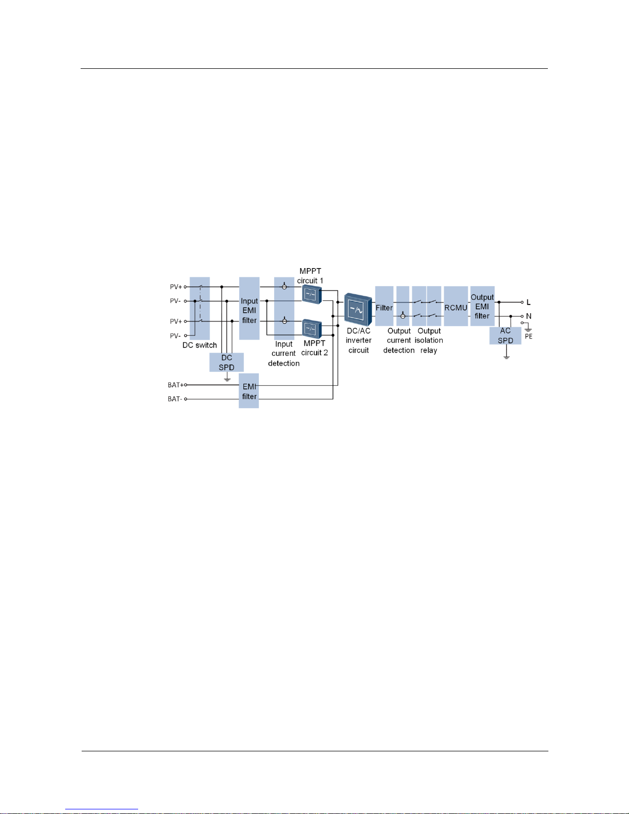
Conceptual Diagram
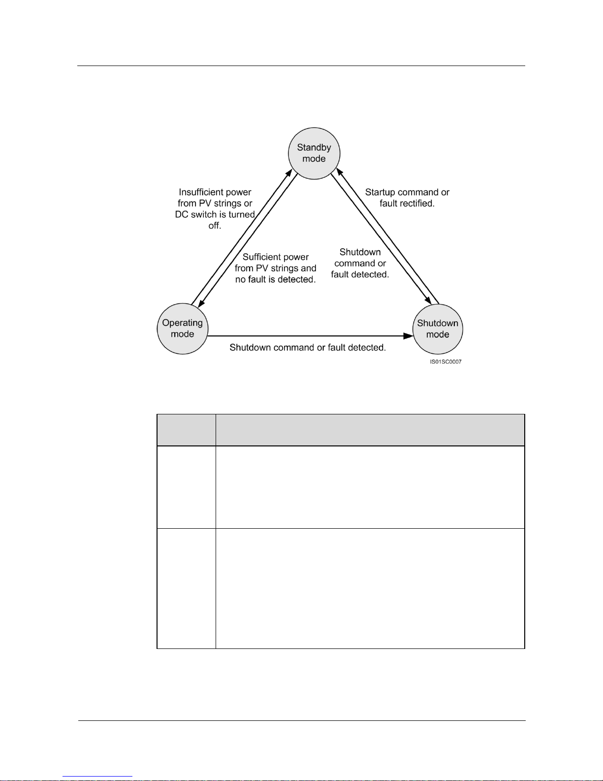
The SUN2000L receives two inputs from the two PV strings. Two MPPT circuits are
configured inside the SUN2000L. Each circuit tracks the maximum power point of one PV
string respectively.
The SUN2000L reserves a battery port to connect to batteries which are used to store the
surplus power produced by PV strings and not required by residential loads. The power stored
in batteries can be exported to the power grid based on the load condition to meet peak power
consumption requirements and maximize the benefits.
Figure 2-10 Conceptual diagram
Page 22
SUN2000L-(2KTL-5KTL)
User Manual
2 Product Overview
Issue 02 (2017-12-12)
Huawei Proprietary and Confidential
Copyright © Huawei Technologies Co., Ltd.
15
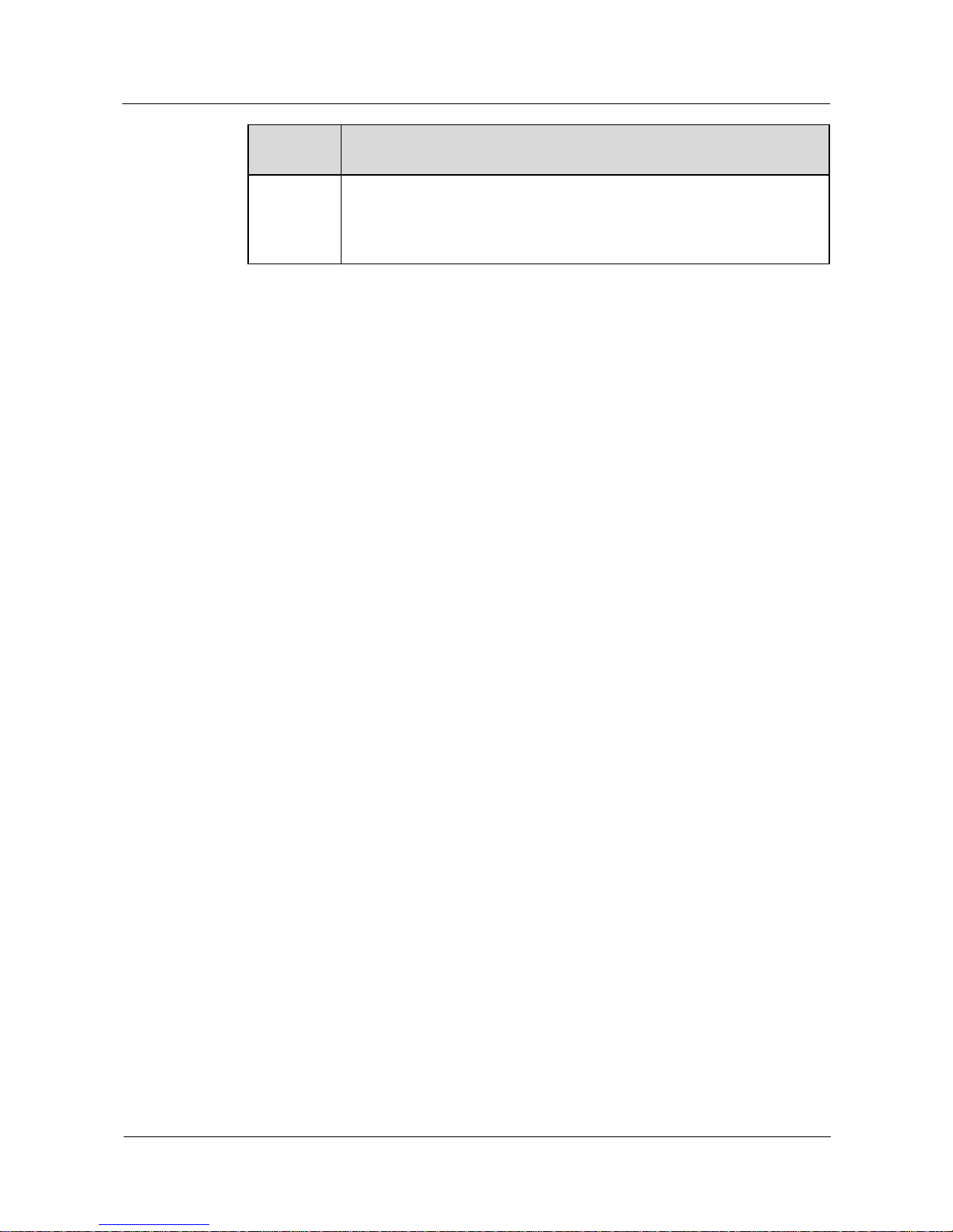
Working Modes
Figure 2-11 Working modes
Table 2-5 Working mode description
Working
Mode
Description
Standby
The SUN2000L enters Standby mode when the external environment does
not meet the requirements for starting the SUN2000L. In Standby mode:
The SUN2000L continuously checks its status and enters Operating
mode once the operating requirements are met.
The SUN2000L enters Shutdown mode after detecting a shutdown
command or a fault after startup.
Operating
In Operating mode:
The SUN2000L converts DC power from PV strings into AC power and
feeds the energy to the power grid.
The SUN2000L tracks the maximum power point to maximize the PV
string output.
The SUN2000L enters Shutdown mode after detecting a fault or a
shutdown command, and enters Standby mode after detecting that the
PV string output power is not suitable for connecting to the power grid
and producing power.
Page 23
SUN2000L-(2KTL-5KTL)
User Manual
2 Product Overview
Issue 02 (2017-12-12)
Huawei Proprietary and Confidential
Copyright © Huawei Technologies Co., Ltd.
16
Working
Mode
Description
Shutdown
In Standby or Operating mode, the SUN2000L enters Shutdown mode
after detecting a fault or shutdown command.
In Shutdown mode, the SUN2000L enters Standby mode after detecting
a startup command or that the fault is rectified.
Page 24

SUN2000L-(2KTL-5KTL)
User Manual
3 Storage
Issue 02 (2017-12-12)
Huawei Proprietary and Confidential
Copyright © Huawei Technologies Co., Ltd.
17
3 Storage
The following requirements should be met when the SUN2000L needs to be stored prior to
installation:
Do not unpack the SUN2000L.
Keep the storage temperature at –40°C to +70°C and the humidity at 5%–95% RH.
The SUN2000L should be stored in a clean and dry place and be protected from dust and
water vapor corrosion.
A maximum of 10 SUN2000Ls can be stacked. To avoid personal injury or device
damage, stack SUN2000Ls with caution to prevent them from falling over.
Regular inspection is required during the storage. Replace the packing materials when
necessary.
After long-term storage, an inspection and test conducted by qualified persons are
necessary before the SUN2000L is put into use.
Page 25
SUN2000L-(2KTL-5KTL)
User Manual
4 System Installation
Issue 02 (2017-12-12)
Huawei Proprietary and Confidential
Copyright © Huawei Technologies Co., Ltd.
18
4 System Installation
4.1 Checking Before Installation
Outer Packing Materials
Before unpacking the SUN2000L, check the outer packing materials for damage, such as
holes and cracks, and check the SUN2000L model. If any damage is found or the SUN2000L
model is not what you requested, do not unpack the package and contact your supplier as soon
as possible.
You are advised to remove the packing materials within 24 hours before installing the
SUN2000L.
Package Contents
After unpacking the SUN2000L, check that the contents are intact and complete. If any
damage is found or any component is missing, contact your supplier.
For details about the number of contents, see the Packing List in the packing case.
Page 26
SUN2000L-(2KTL-5KTL)
User Manual
4 System Installation
Issue 02 (2017-12-12)
Huawei Proprietary and Confidential
Copyright © Huawei Technologies Co., Ltd.
19
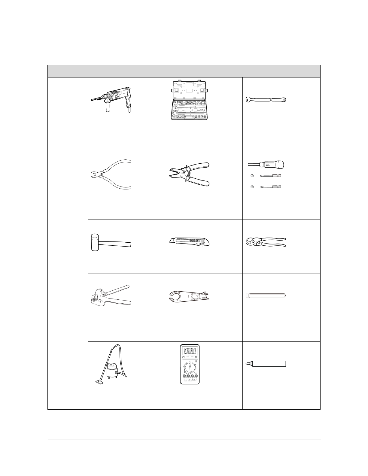
4.2 Tools and Instruments
Category
Tools and Instruments
Installation
Hammer drill (with a Ф10
mm drill bit)
Torque socket wrench (open
end: 13 mm, applicable for
M8 bolts; torque range: 0–15
N•m)
Torque wrench (open end: 13
mm; torque range: 0–1.5
N•m)
Diagonal pliers
Wire stripper
Torque screwdriver (head:
M4 or M6; torque range: 0–5
N•m)
Rubber mallet
Utility knife
Cable cutter
Crimping tool (model:
H4TC0001; manufacturer:
Amphenol)
Open-end wrench (model:
H4TW0001; manufacturer:
Amphenol)
Cable tie
Vacuum cleaner
Multimeter (DC voltage
measurement range ≥ 600 V
DC)
Marker
Page 27
SUN2000L-(2KTL-5KTL)
User Manual
4 System Installation
Issue 02 (2017-12-12)
Huawei Proprietary and Confidential
Copyright © Huawei Technologies Co., Ltd.
20
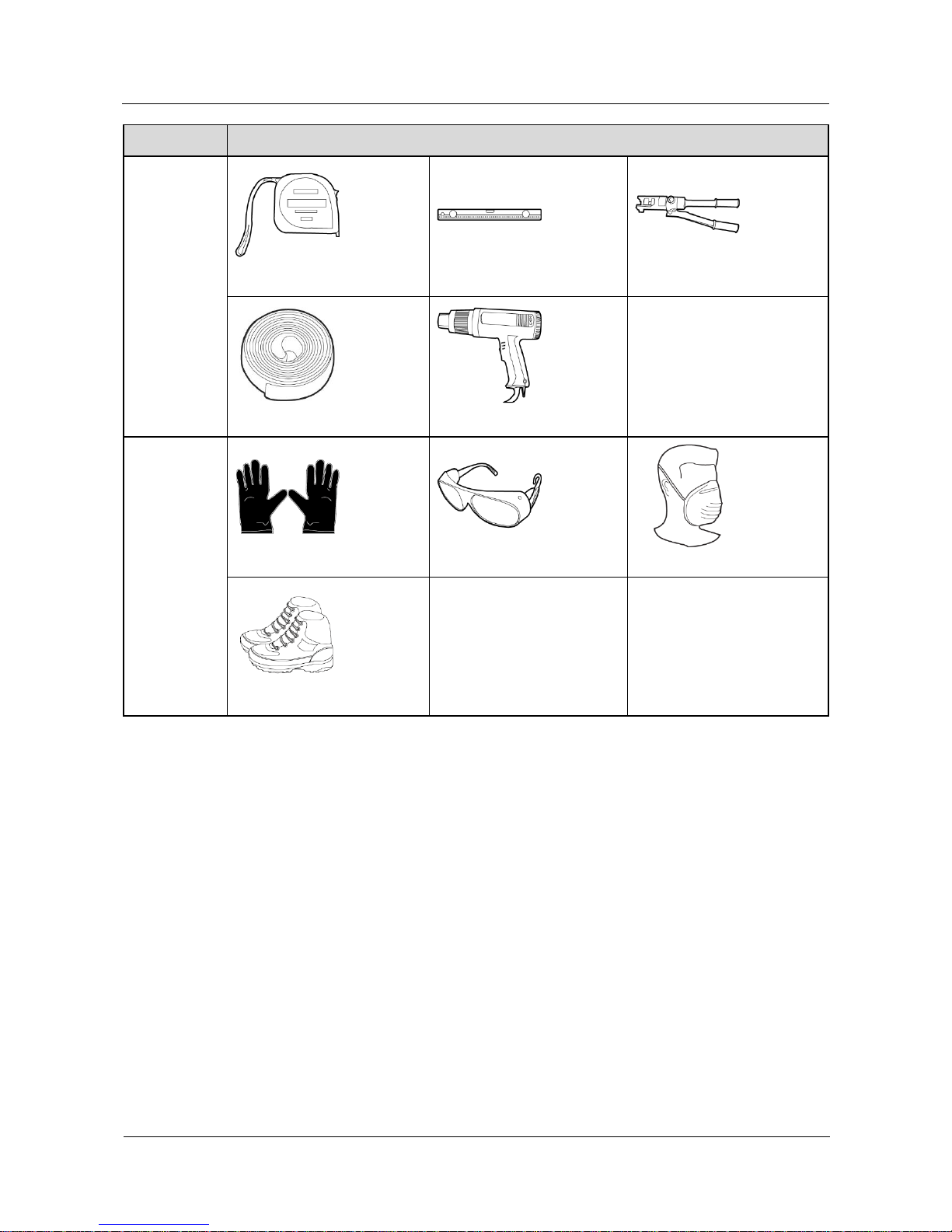
Category
Tools and Instruments
Measuring tape
Bubble or digital level
Hydraulic pliers
Heat shrink tubing
Heat gun
N/A
PPE
Safety gloves
Safety goggles
Anti-dust respirator
Safety shoes
N/A
N/A
4.3 Determining the Installation Position
Basic Requirements
The SUN2000L is protected to IP65 and can be installed indoors or outdoors.
Do not install the SUN2000L in a place where a person can be easy to come into contact
with its enclosure and heat sinks, because these parts are extremely hot during operation.
Do not install the SUN2000L in areas with flammable or explosive materials.
Do not install the SUN2000L at a place within children's reach.
The SUN2000L will be corroded in salt areas, and the salt corrosion may cause fire. Do
not install the SUN2000L outdoors in salt areas. A salt area refers to the region within
500 meters from the coast or prone to sea breeze. The regions prone to sea breeze vary
depending on weather conditions (such as typhoons and monsoons) or terrains (such as
dams and hills).
Page 28
SUN2000L-(2KTL-5KTL)
User Manual
4 System Installation
Issue 02 (2017-12-12)
Huawei Proprietary and Confidential
Copyright © Huawei Technologies Co., Ltd.
21
Installation Environment Requirements
The SUN2000L must be installed in a well-ventilated environment to ensure good heat
dissipation.
When installed under direct sunlight, performance de-rate may be initiated due to
additional temperature rise.
Install the SUN2000L in a sheltered place or install an awning over the SUN2000L.
Mounting Structure Requirements
The mounting structure where the SUN2000L is installed must be fireproof.
Do not install the SUN2000L on flammable building materials.
Ensure that the installation surface is solid enough to bear the weight load.
In residential areas, do not install the SUN2000L on drywalls or walls made of similar
materials which have a weak sound insulation performance because the noise generated
by the SUN2000L is noticeable.
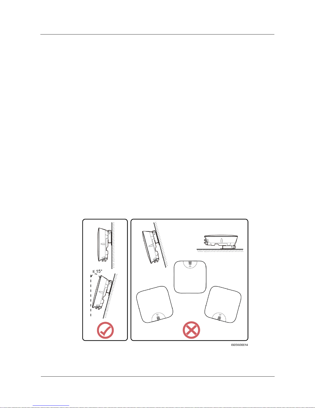
Installation Angle Requirements
The SUN2000L can be wall-mounted or pole-mounted. The installation angle requirements
are as follows:
Install the SUN2000L vertically or at a maximum back tilted angle of 15 degrees to
facilitate heat dissipation.
Do not install the SUN2000L at forward tilted, excessive back tilted, side tilted,
horizontal, or upside down positions.
Figure 4-1 Installation angle
Page 29
SUN2000L-(2KTL-5KTL)
User Manual
4 System Installation
Issue 02 (2017-12-12)
Huawei Proprietary and Confidential
Copyright © Huawei Technologies Co., Ltd.
22
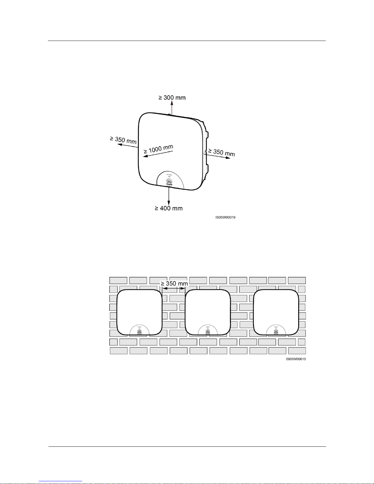
Installation Space Requirements
Reserve enough clearance around the SUN2000L to ensure sufficient space for
installation and heat dissipation.
Figure 4-2 Installation space requirements
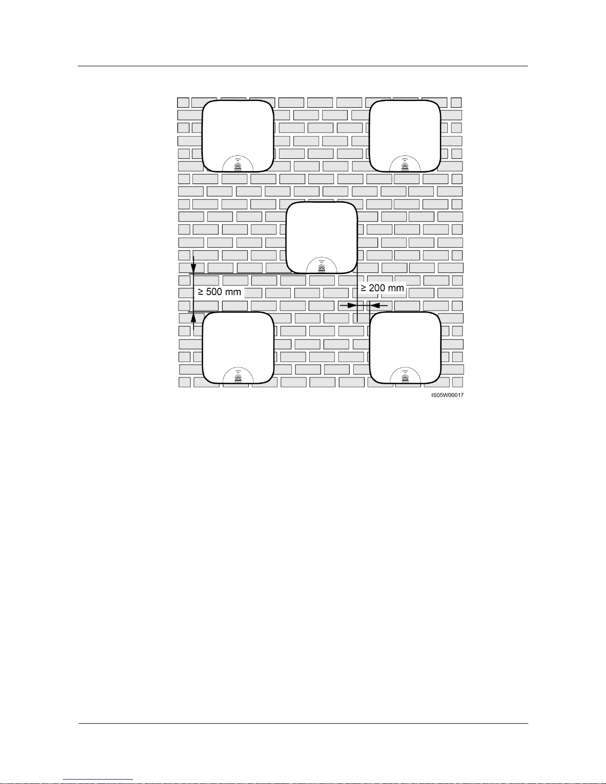
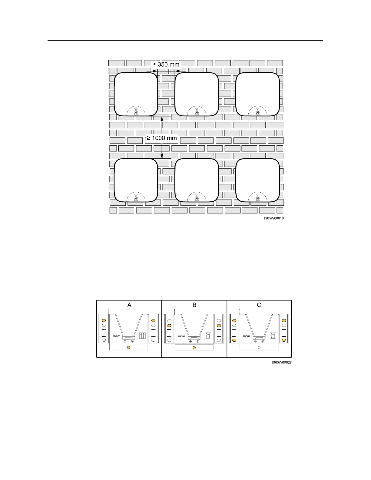
When installing multiple SUN2000Ls, install them in horizontal mode if sufficient space
is available and install them in triangle mode if no sufficient space is available. Stacked
installation is not recommended.
Figure 4-3 Horizontal installation mode (recommended)
Page 30
SUN2000L-(2KTL-5KTL)
User Manual
4 System Installation
Issue 02 (2017-12-12)
Huawei Proprietary and Confidential
Copyright © Huawei Technologies Co., Ltd.
23
Figure 4-4 Triangle installation mode (recommended)
Page 31
SUN2000L-(2KTL-5KTL)
User Manual
4 System Installation
Issue 02 (2017-12-12)
Huawei Proprietary and Confidential
Copyright © Huawei Technologies Co., Ltd.
24
Figure 4-5 Stacked installation mode (not recommended)
4.4 Installing the Mounting Bracket
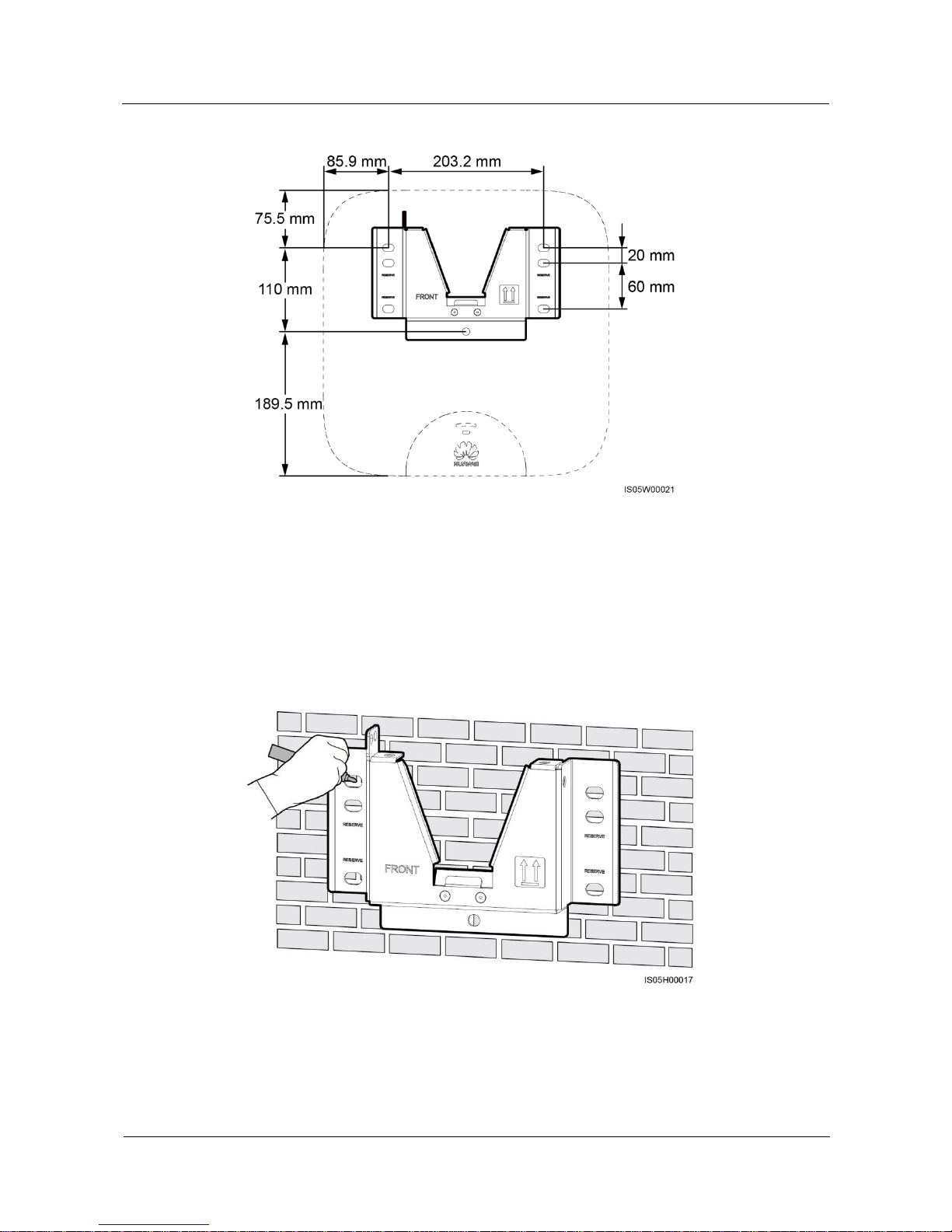
Fixing holes can be used in three combinations. Select a hole combination based on site
requirements. Combination A is preferred.
Figure 4-6 Hole combinations
Page 32
SUN2000L-(2KTL-5KTL)
User Manual
4 System Installation
Issue 02 (2017-12-12)
Huawei Proprietary and Confidential
Copyright © Huawei Technologies Co., Ltd.
25
Figure 4-7 Hole distances
4.4.1 Wall-Mounted Installation
Procedure
Step 1 Determine the positions for drilling holes using the mounting bracket. Level the positions of
mounting holes using a bubble or digital level, and mark the positions with a marker.
Figure 4-8 Determining hole positions
Step 2 Install expansion bolts.
Page 33
SUN2000L-(2KTL-5KTL)
User Manual
4 System Installation
Issue 02 (2017-12-12)
Huawei Proprietary and Confidential
Copyright © Huawei Technologies Co., Ltd.
26
Avoid drilling holes in the utility pipes and/or cables attached to back of the wall.
If the length or number of M8x80 expansion bolts supplied with the SUN2000L is not enough, prepare
M8 stainless steel expansion anchor bolts.
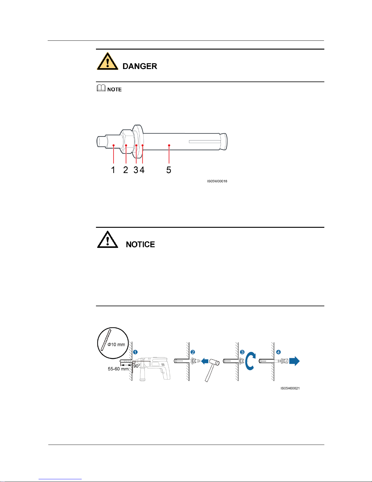
Figure 4-9 Expansion bolt composition
(1) Bolt
(2) Nut
(3) Spring washer
(4) Flat washer
(5) Expansion sleeve
To prevent dust inhalation or contact with eyes, wear safety goggles and an anti-dust
respirator when drilling holes.
Clean up any dust in and around the holes using a vacuum cleaner and measure the
distance between holes. If the holes are inaccurately positioned, drill new set of the holes.
Level the head of the expansion sleeve with the concrete wall after removing the bolt,
spring washer, and flat washer. Otherwise, the mounting bracket will not be securely
installed on the concrete wall.
Figure 4-10 Installing an expansion bolt
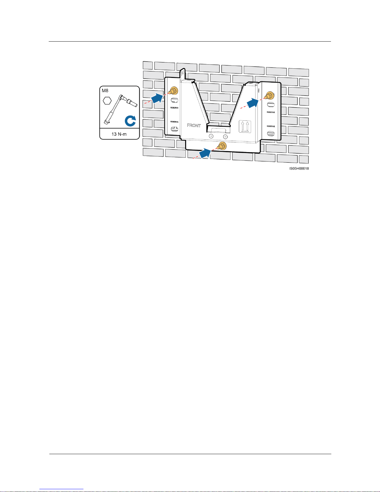
Step 3 Secure the mounting bracket.
Page 34
SUN2000L-(2KTL-5KTL)
User Manual
4 System Installation
Issue 02 (2017-12-12)
Huawei Proprietary and Confidential
Copyright © Huawei Technologies Co., Ltd.
27
Figure 4-11 Securing a mounting bracket
----End
4.4.2 Support-mounted Installation
Prerequisites
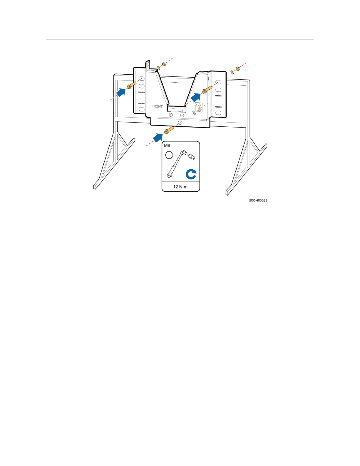
Prepare M8 stainless bolt assemblies (including flat washers, spring washers, and M8 bolts)
with appropriate lengths as well as matched flat washers and nuts based on the support
specifications.
Procedure
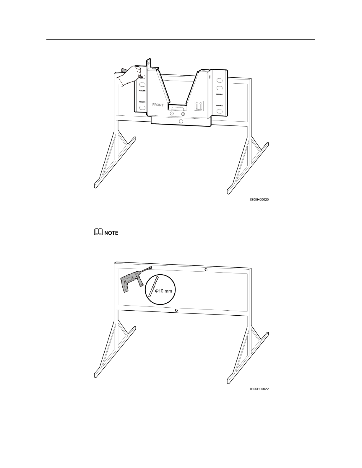
Step 1 Determine the positions for drilling holes using the mounting bracket. Level the positions of
mounting holes using a bubble or digital level, and mark the positions with a marker.
Page 35
SUN2000L-(2KTL-5KTL)
User Manual
4 System Installation
Issue 02 (2017-12-12)
Huawei Proprietary and Confidential
Copyright © Huawei Technologies Co., Ltd.
28
Figure 4-12 Determining hole positions
Step 2 Drill holes using a hammer drill.
You are advised to apply anti-rust paint on the hole positions for protection.
Figure 4-13 Drilling holes
Step 3 Secure the mounting bracket.
Page 36
SUN2000L-(2KTL-5KTL)
User Manual
4 System Installation
Issue 02 (2017-12-12)
Huawei Proprietary and Confidential
Copyright © Huawei Technologies Co., Ltd.
29
Figure 4-14 Securing a mounting bracket
----End
4.5 Installing the SUN2000L
Procedure
Step 1 Hold the handles on both sides of the SUN2000L, lift the SUN2000L from the packing case,
and move it to the installation position.
Page 37

SUN2000L-(2KTL-5KTL)
User Manual
4 System Installation
Issue 02 (2017-12-12)
Huawei Proprietary and Confidential
Copyright © Huawei Technologies Co., Ltd.
30
To prevent device damage and personal injury, keep balance when moving the SUN2000L.
Do not use the wiring terminals and ports at the bottom to support any weight of the
SUN2000L.
When you need to temporally place the SUN2000L on the ground, use foam, paper or
other protection material to prevent damage to its cover.
Figure 4-15 Moving a SUN2000L
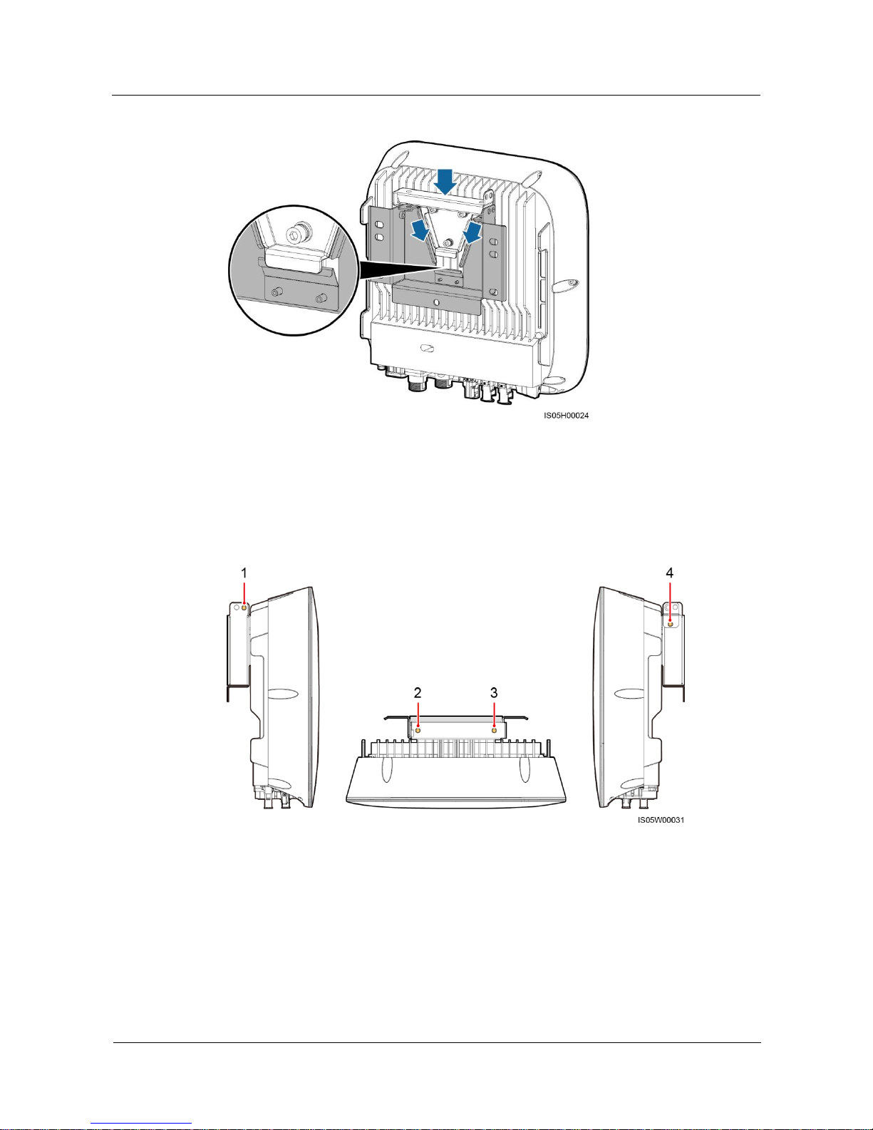
Step 2 Install the SUN2000L on the mounting bracket and align the SUN2000L enclosure with the
mounting bracket.
If the bottom of the mounting plate does not snap into place, push the SUN2000L from the
front until the bottom of the mounting plate snaps into the mounting bracket.
Page 38
SUN2000L-(2KTL-5KTL)
User Manual
4 System Installation
Issue 02 (2017-12-12)
Huawei Proprietary and Confidential
Copyright © Huawei Technologies Co., Ltd.
31
Figure 4-16 Mounting a SUN2000L
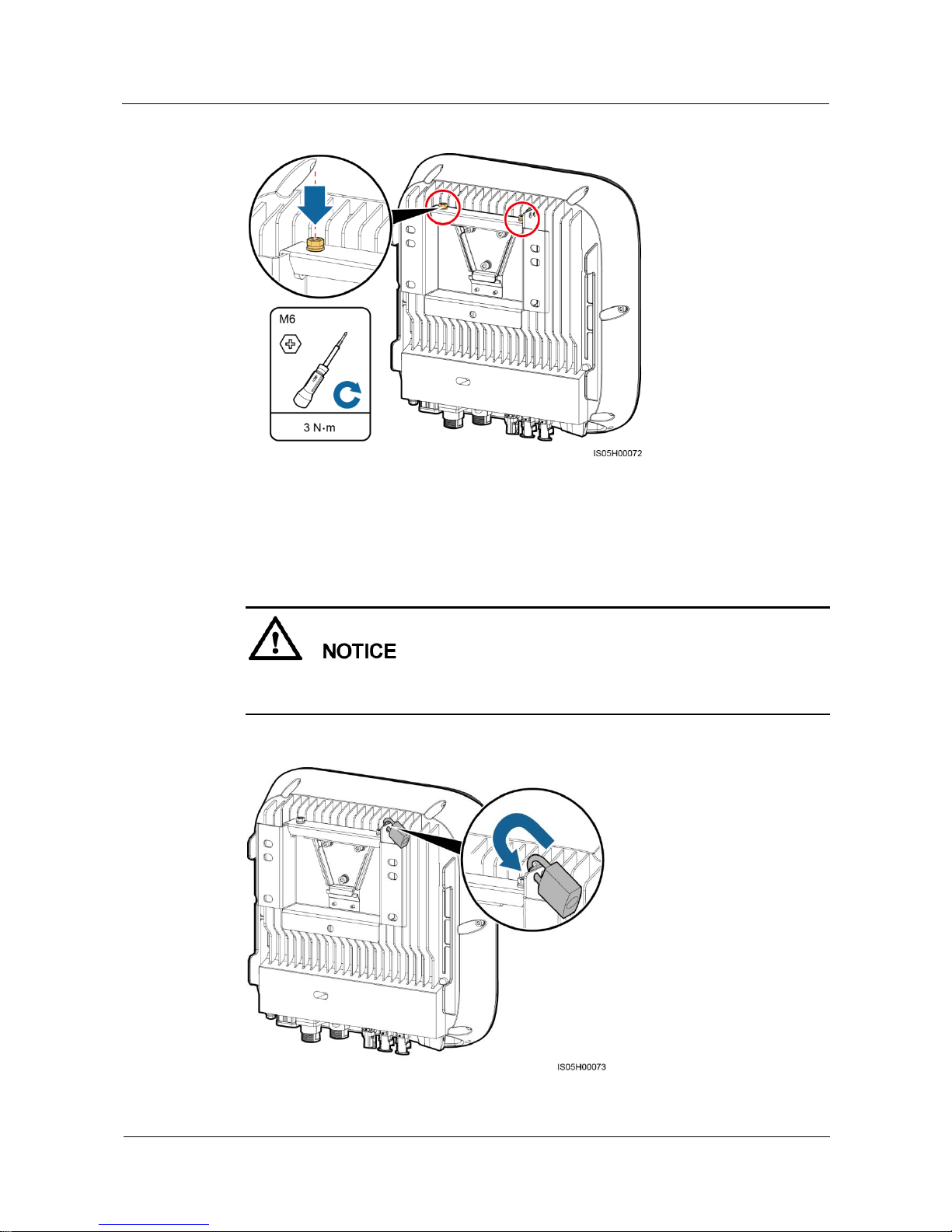
Step 3 Tighten screw assemblies.
Fixing holes can be used in three combinations. Select a hole combination based on site
requirements. Combination A is preferred.
Figure 4-17 Fixing holes
Combination A: holes 2 and 3
Combination B: holes 1 and 3
Combination C: holes 1 and 4
Combination D: holes 2 and 4
Page 39
SUN2000L-(2KTL-5KTL)
User Manual
4 System Installation
Issue 02 (2017-12-12)
Huawei Proprietary and Confidential
Copyright © Huawei Technologies Co., Ltd.
32
Figure 4-18 Tightening screw assemblies
Step 4 (Optional) Install an anti-theft lock.
The function of an anti-theft lock is to secure the SUN2000L to the mounting bracket and
protect it from stealing.
Prepare an anti-theft lock suitable for the lock hole diameter (Ф8 mm) by yourself.
Keep the key to the anti-theft lock safe.
Figure 4-19 Installing an anti-theft lock
Page 40
SUN2000L-(2KTL-5KTL)
User Manual
4 System Installation
Issue 02 (2017-12-12)
Huawei Proprietary and Confidential
Copyright © Huawei Technologies Co., Ltd.
33
----End
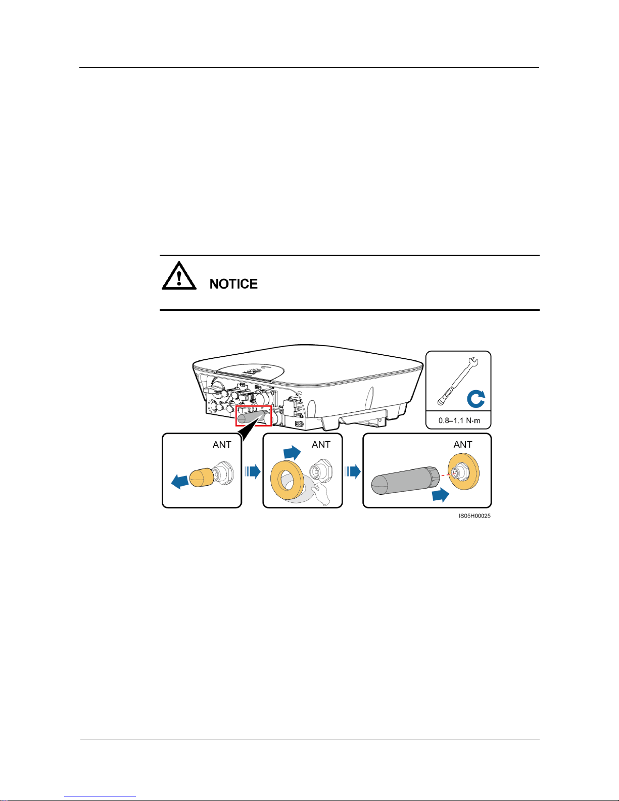
4.6 Installing the WiFi Antenna
Procedure
Step 1 Remove the watertight cap from the ANT port.
Step 2 Remove the release paper of the double-sided tape and attach the washer to the enclosure.
Step 3 Install the WiFi antenna.
Ensure that the WiFi antenna is installed securely.
Figure 4-20 Installing a WiFi antenna
----End
Page 41
SUN2000L-(2KTL-5KTL)
User Manual
5 Electrical Connections
Issue 02 (2017-12-12)
Huawei Proprietary and Confidential
Copyright © Huawei Technologies Co., Ltd.
34
5 Electrical Connections
Precautions
Before connecting cables, ensure that the DC switch on the SUN2000L and all the switches
connecting to the SUN2000L are OFF. Otherwise, the high voltage of the SUN2000L may
result in electric shocks.
The equipment damage caused by incorrect cable connections is beyond the warranty
scope.
Only certified electricians are allowed to connect cables.
Operation personnel must wear proper PPE all the time when connecting cables.
The cable colors shown in the electrical connection diagrams provided in this chapter are for reference
only. Select cables in accordance with local cable specifications (green-and-yellow cables are only used
for PE).
Page 42
SUN2000L-(2KTL-5KTL)
User Manual
5 Electrical Connections
Issue 02 (2017-12-12)
Huawei Proprietary and Confidential
Copyright © Huawei Technologies Co., Ltd.
35
5.1 Preparing Cables
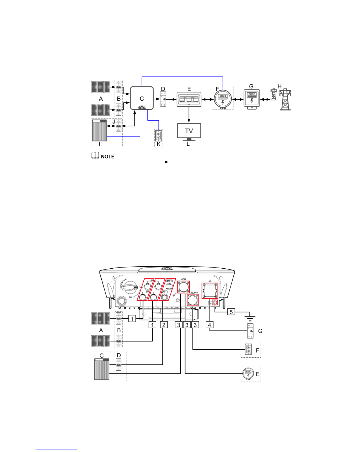
Figure 5-1 Network diagram (optional in dashed boxes)
indicates a power cable, indicates the power flow direction, and indicates a signal
cable.
(A) PV string
(B) DC switch
(C) SUN2000L
(D) AC switch
(E) Residential power distribution
unit
(F) Energy meter
(G) Residential power
meter
(H) Power grid
(I) Battery
(J) Battery switch
(K) Alarm beacon
(L) Residential
load
Figure 5-2 SUN2000L cable connections (optional in dashed boxes)
Page 43

SUN2000L-(2KTL-5KTL)
User Manual
5 Electrical Connections
Issue 02 (2017-12-12)
Huawei Proprietary and Confidential
Copyright © Huawei Technologies Co., Ltd.
36
Table 5-1 Component description
No.
Component
Description
Source
A
PV string
A PV string is composed of the PV
modules connected in series and works
with an optimizer.
The SUN2000L supports the input from
two PV strings.
Prepared by the customer
B
DC switch
Recommended: a DC circuit breaker with a
rated voltage greater than or equal to 600 V
DC and a rated current of 20 A
Prepared by the customer
C
Battery
The batteries that can connect to the
SUN2000L are LG-RESU (LG RESU7H
and RESU10H).
Prepared by the customer
D
Battery switch
Recommended: a DC circuit breaker with a
rated voltage greater than or equal to 600 V
DC and a rated current of 20 A
Prepared by the customer
E
Energy meter
The energy meters that can connect to the
SUN2000L are CHINT-DDSU666,
CCS-WNC-3Y-400-MB,
Gavazzi-EM340DINAV23XS1X, and
Gavazzi-EM111DINAV81XS1X.
Prepared by the customer
F
Alarm beacon
The rated voltage is 12 V and the power is
less than or equal to 3 W.
Prepared by the customer
G
AC switch
Recommended: a single-phase AC circuit
breaker with a rated voltage greater than or
equal to 250 V AC and a rated current of
16 A (SUN2000L-2KTL)
25 A (SUN2000L-3KTL and
SUN2000L-3.68KTL)
32 A (SUN2000L-4KTL,
SUN2000L-4.6KTL, and
SUN2000L-5KTL)
Prepared by the customer
Page 44
SUN2000L-(2KTL-5KTL)
User Manual
5 Electrical Connections
Issue 02 (2017-12-12)
Huawei Proprietary and Confidential
Copyright © Huawei Technologies Co., Ltd.
37
The SUN2000L is embedded with a residual current monitoring unit (RCMU). Only a
single-phase circuit breaker or a similar AC load breaking device is required to function as
the external AC switch (shown by G in Figure 5-2) to ensure that the SUN2000L can be
safely disconnected from the power grid.
If the external AC switch can perform earth leakage protection, the rated leakage action
current should be greater than or equal to 100 mA.
If multiple SUN2000Ls connect to the general residual current device (RCD) through their
respective external AC switches, the rated leakage action current of the general RCD
should be greater than or equal to the number of SUN2000Ls multiplied by 100 mA.
A knife switch cannot be used as an AC switch.
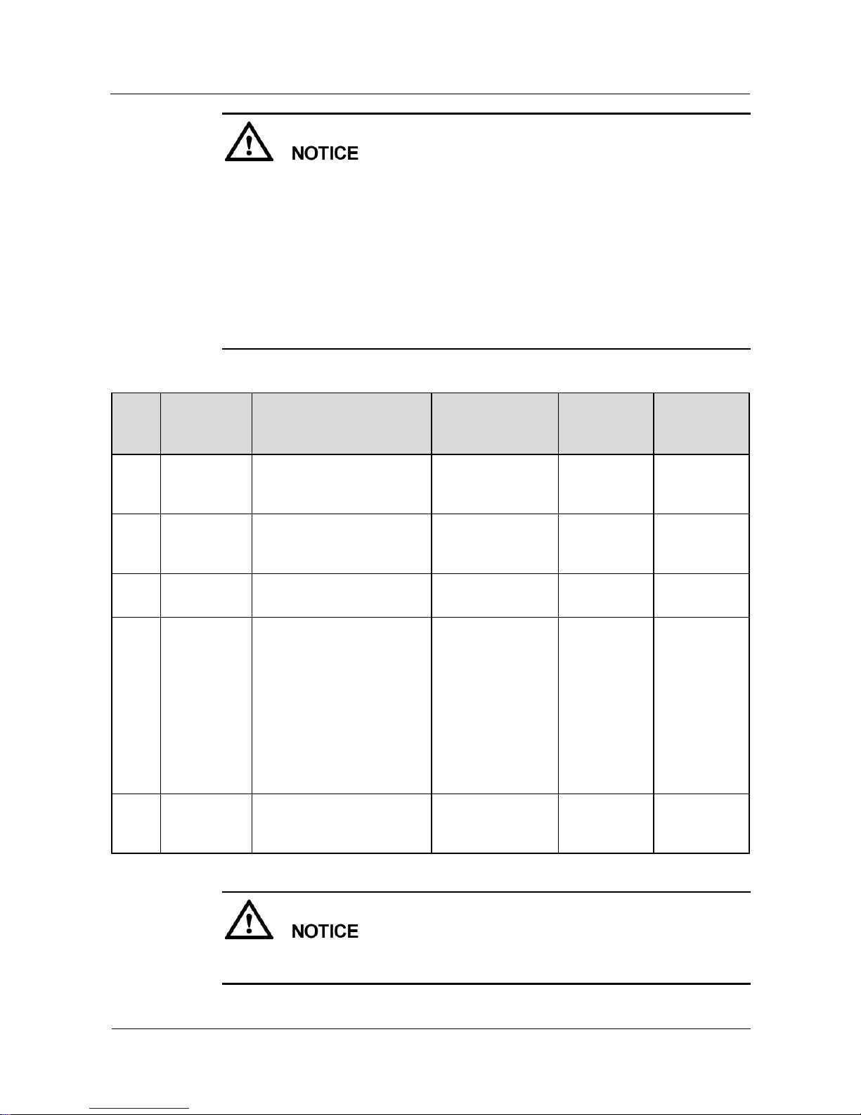
Table 5-2 Cable description
No.
Cable
Type
Conductor
Cross-sectional
Area Range
Outer
Diameter
Source
1
DC input
power cable
Standard PV cable in the
industry (recommended
model: PV1-F)
4–6 mm2
4.5–7.8 mm
Prepared by
the customer
2
Battery cable
Standard PV cable in the
industry (recommended
model: PV1-F)
4–6 mm2
4.5–7.8 mm
Prepared by
the customer
3
Signal cable
Four-core outdoor shielded
twisted pair
0.25–1 mm2
4–11 mm
Prepared by
the customer
4
AC output
power cable
Not using the PE
equipotential point at the
AC output port: two-core
(L and N) outdoor copper
cable
Using the PE
equipotential point at the
AC output port:
three-core (L, N, and PE)
outdoor copper cable
4–6 mm2
10–21 mm
Prepared by
the customer
5
PE cable
Single-core outdoor copper
cable with an M6 OT
terminal
4–10 mm2
N/A
Prepared by
the customer
The PE point at the AC output port is used only as a PE equipotential point, and cannot
substitute for the PE point on the enclosure.
Page 45
SUN2000L-(2KTL-5KTL)
User Manual
5 Electrical Connections
Issue 02 (2017-12-12)
Huawei Proprietary and Confidential
Copyright © Huawei Technologies Co., Ltd.
38
5.2 Installing the PE Cable
Context
Do not connect the neutral wire to the enclosure as a PE cable. Otherwise, electric shocks will
be caused.
Procedure
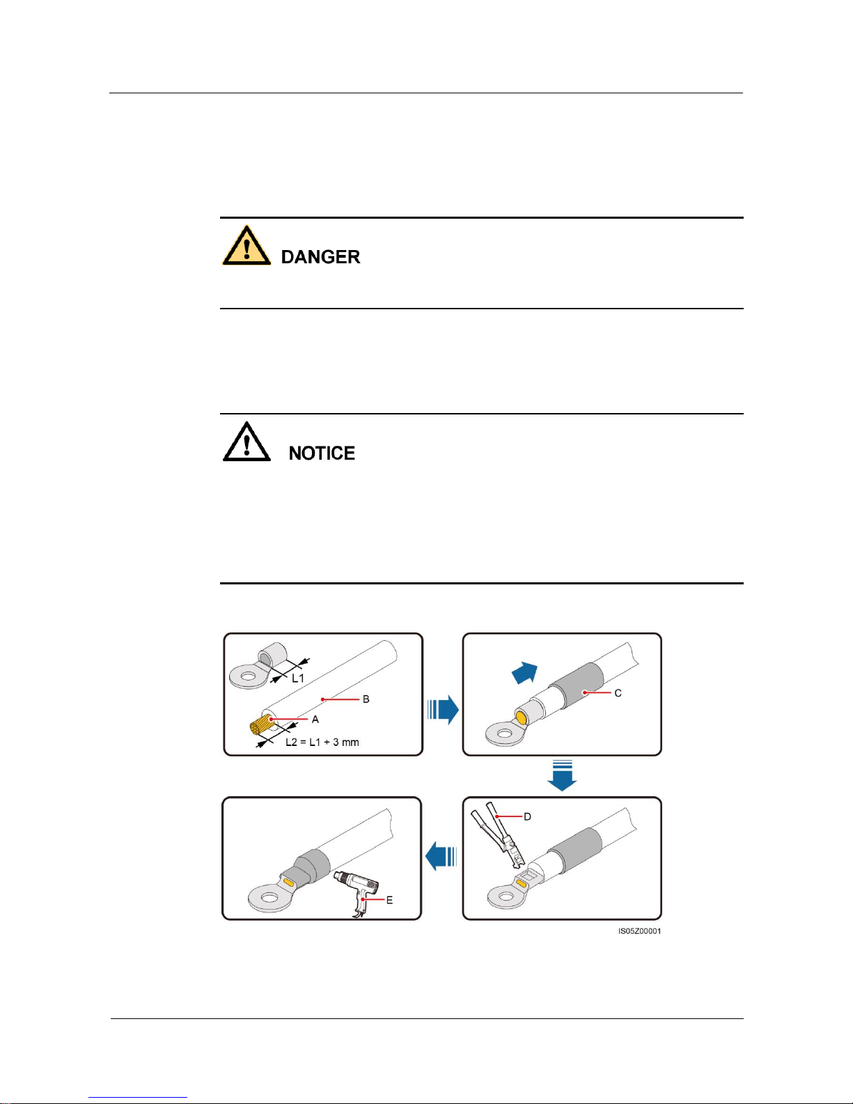
Step 1 Crimp the OT terminal.
Pay attention not to damage the core wire when stripping a cable.
The cavity formed after the conductor crimp strip of the OT terminal is crimped must wrap
the core wires completely. The core wires must contact the OT terminal closely.
Wrap the wire crimping area with heat shrink tubing or PVC insulation tape. The
following figure uses heat shrink tubing as an example.
When using the heat gun, protect devices from being scorched.
Figure 5-3 Crimping an OT terminal
(A) Core wire
(B) Insulation layer
(C) Heat shrink tubing
Page 46
SUN2000L-(2KTL-5KTL)
User Manual
5 Electrical Connections
Issue 02 (2017-12-12)
Huawei Proprietary and Confidential
Copyright © Huawei Technologies Co., Ltd.
39
(D) Hydraulic pliers
(E) Heat gun
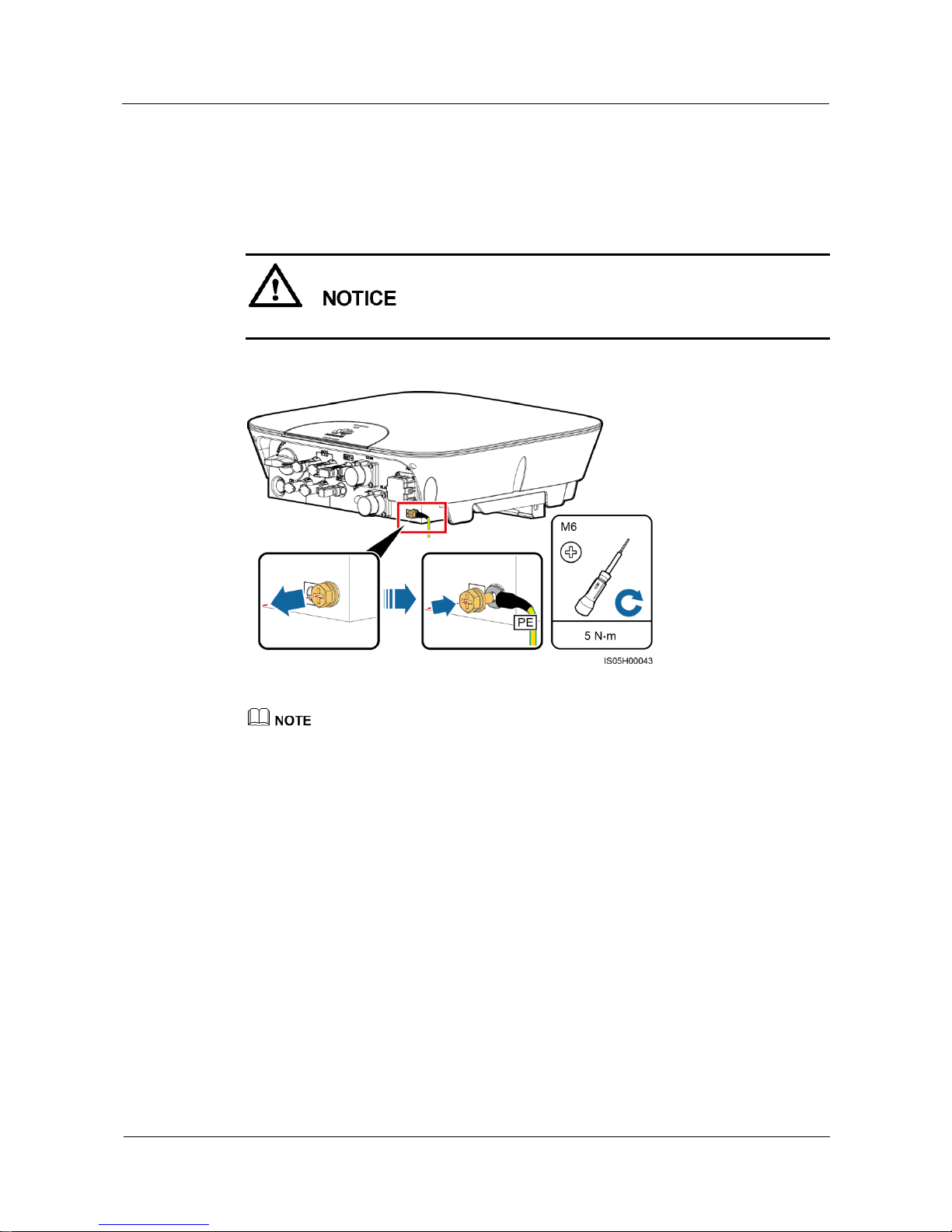
Step 2 Connect the PE cable.
Ensure that the PE cable is connected securely.
Figure 5-4 Connecting a PE cable
The PE point at the AC output port is used only as a PE equipotential point, and cannot substitute for
the PE point on the enclosure.
To enhance the corrosion resistance of a ground terminal, apply silica gel or paint around the
terminal after connecting the ground cable.
----End
5.3 Installing the AC Output Power Cable
Prerequisites
An AC switch must be installed on the AC side of the SUN2000L to ensure that the
SUN2000L can be safely disconnected from the power grid.
Page 47
SUN2000L-(2KTL-5KTL)
User Manual
5 Electrical Connections
Issue 02 (2017-12-12)
Huawei Proprietary and Confidential
Copyright © Huawei Technologies Co., Ltd.
40
Do not connect any load between the SUN2000L and the AC switch.
Context
The SUN2000L can detect the grounding. This function is used to detect whether the
SUN2000L is properly grounded before starting the SUN2000L, or to detect whether the PE
cable is disconnected when the SUN2000L is working. This function is available only under
limited conditions. To ensure the safe operation of the SUN2000L, properly ground the
SUN2000L in strict accordance with the connection requirements for PE cables. For certain
types of power grids, if an isolation transformer connects to the output side of the SUN2000L,
you need to set OFF due to abnormal grounding to Disable (see 7.4.5.3 Feature Parameters
for details) after checking that the SUN2000L is properly grounded. Then the SUN2000L can
start normally. If you are not sure whether the SUN2000L connects to such a power grid,
confirm it with your dealer or Huawei technical support.
According to IEC62109, to ensure the safe operation of the SUN2000L in the case of PE cable
damage or disconnection, connect the SUN2000L PE cable according to the requirements described
in 5.2 Installing the PE Cable and ensure that the SUN2000L PE cable meets at least one of the
following requirements before disabling the grounding detection function.
The SUN2000L PE cable is a copper cable with a cross-sectional area of at least 10 mm2.
Use two cables that have the same diameter as the AC output power cable to ground the PE terminal
on the AC connector and the ground screw on the enclosure respectively (see 5.2 Installing the PE
Cable and 5.3 Installing the AC Output Power Cable for details).
Certain countries require an additional PE cable for the SUN2000L. In this case, use two cables that
have the same diameter as the AC output power cable to ground the PE terminal on the AC
connector and the ground screw on the enclosure respectively (see 5.2 Installing the PE Cable and
5.3 Installing the AC Output Power Cable for details).
Procedure
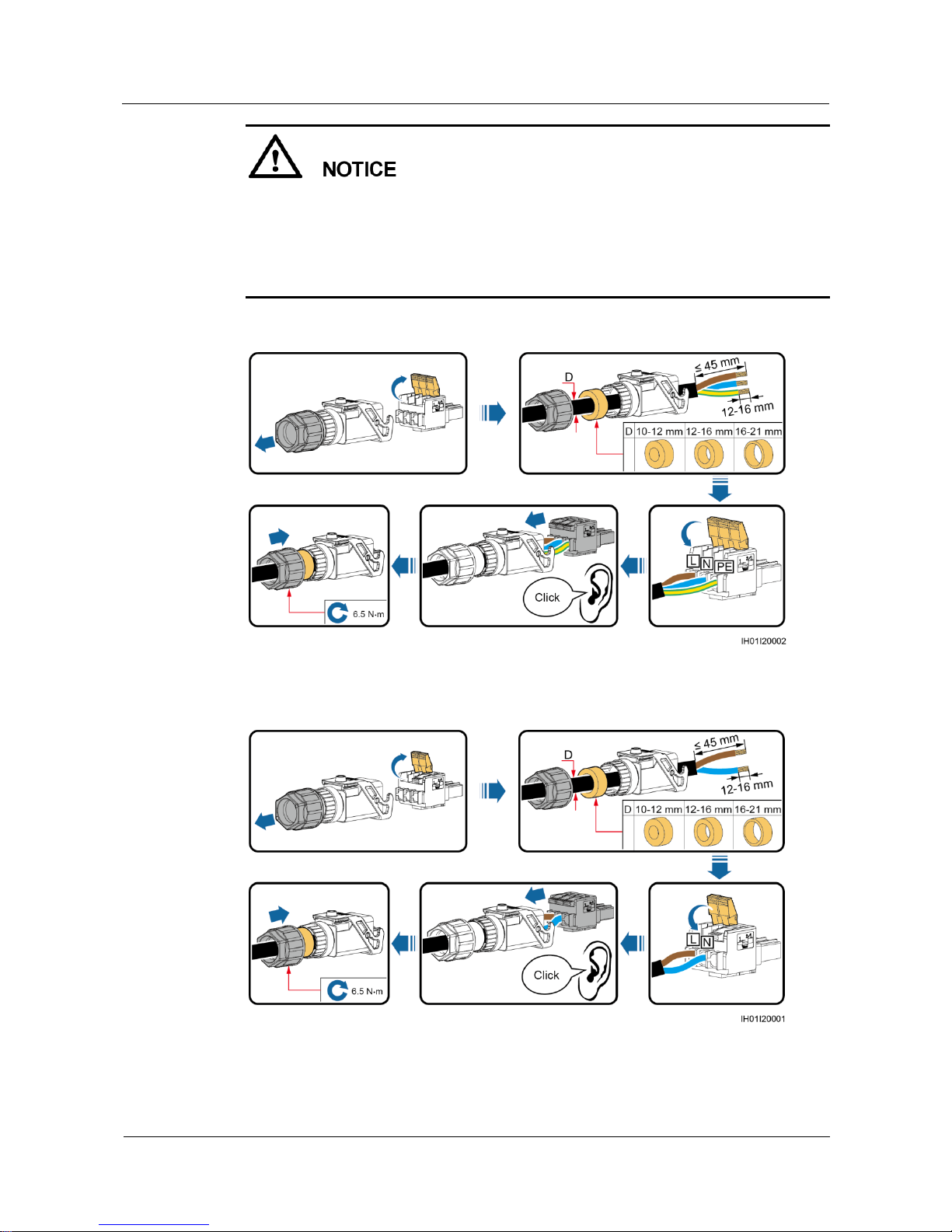
Step 1 Connect the AC output power cable to the AC connector.
Page 48
SUN2000L-(2KTL-5KTL)
User Manual
5 Electrical Connections
Issue 02 (2017-12-12)
Huawei Proprietary and Confidential
Copyright © Huawei Technologies Co., Ltd.
41
Ensure that the cable jacket is inside the connector.
Ensure that the exposed core wire is totally inserted into the cable hole.
Ensure that AC terminations provide firm and solid electrical connections. Failing to do so
may cause SUN2000L malfunction and damage to its AC connectors.
Ensure that the cable is not twisted.
Figure 5-5 Assembling an AC connector (three-core wire)
Figure 5-6 Assembling an AC connector (two-core wire)
Page 49
SUN2000L-(2KTL-5KTL)
User Manual
5 Electrical Connections
Issue 02 (2017-12-12)
Huawei Proprietary and Confidential
Copyright © Huawei Technologies Co., Ltd.
42
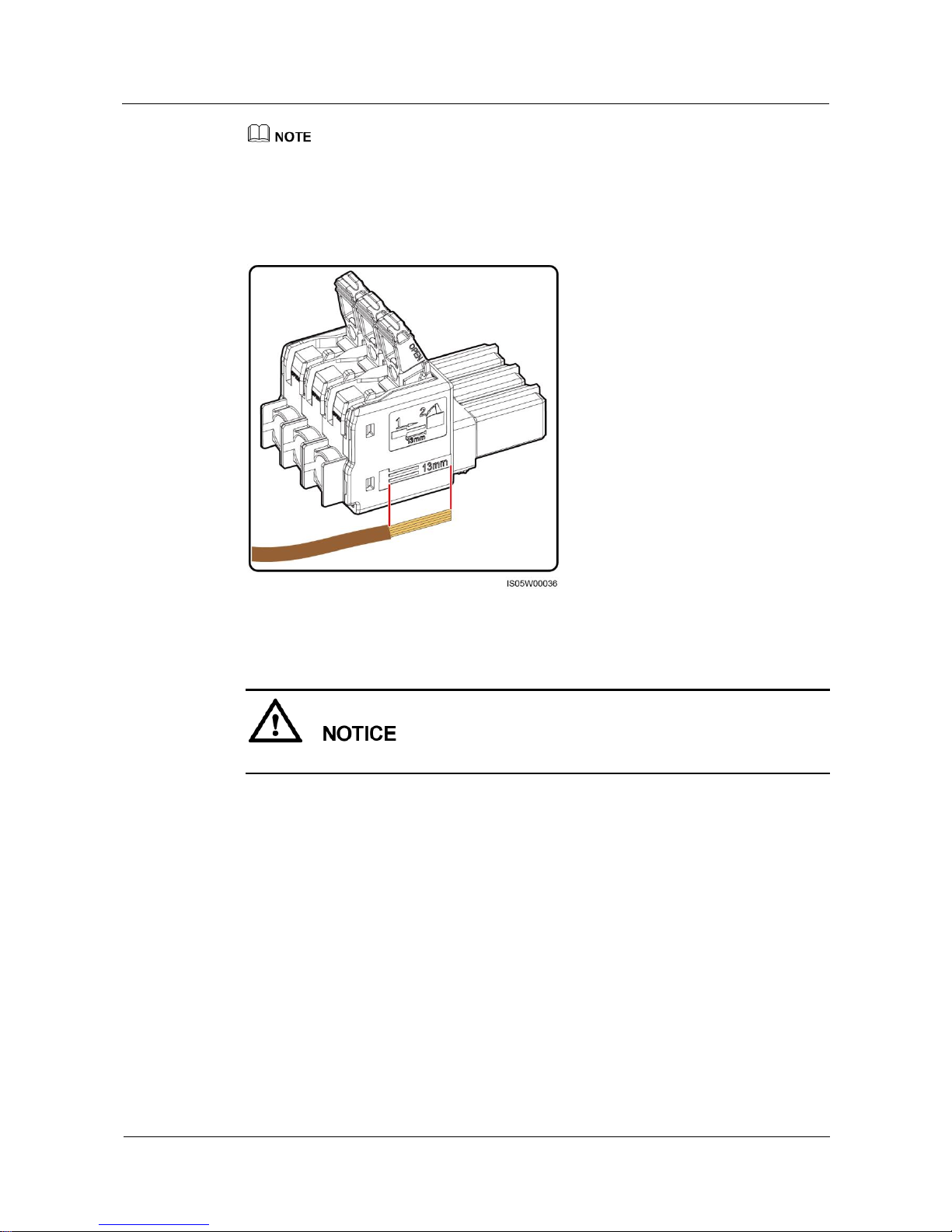
The cable colors shown in figures are for reference only. Select an appropriate cable according to the
local standards.
For the core wire installation method and stripped length, see the instructions on the side of the plug
insert.
Figure 5-7 Stripped length
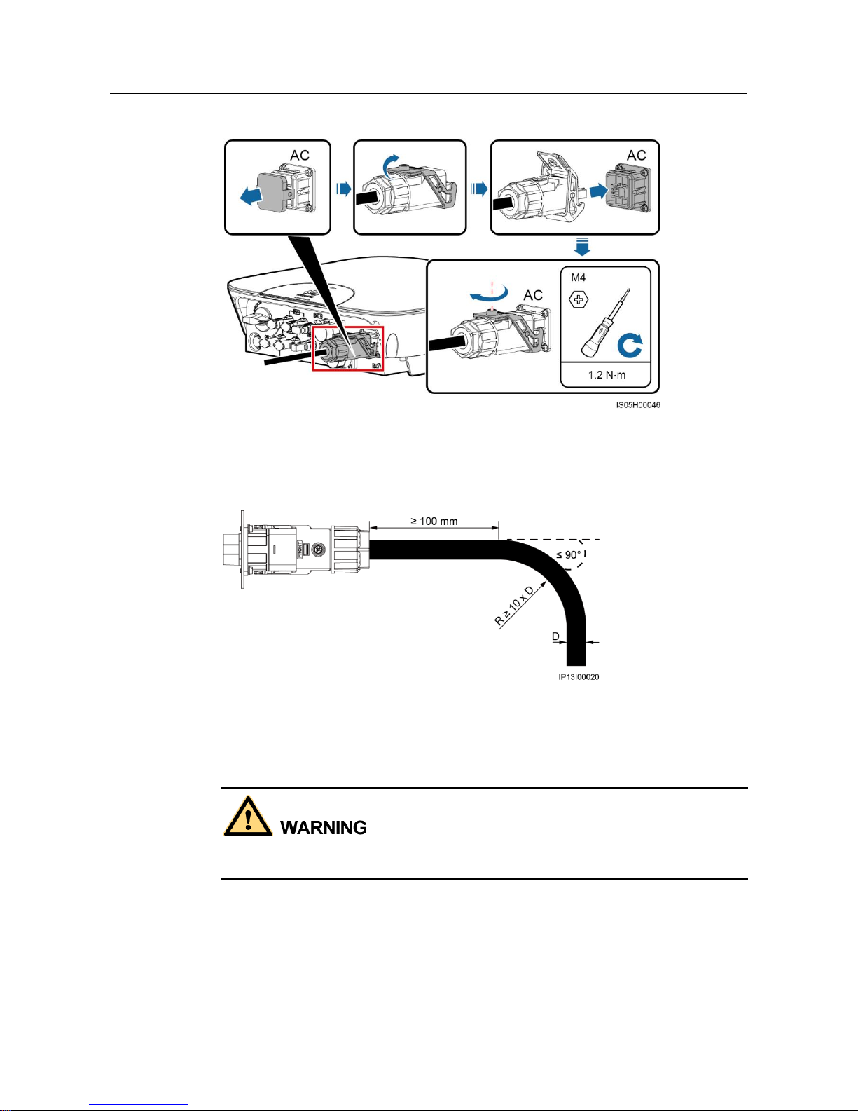
Step 2 Connect the AC connector to the AC output port.
Ensure that the AC connector is connected securely.
Page 50
SUN2000L-(2KTL-5KTL)
User Manual
5 Electrical Connections
Issue 02 (2017-12-12)
Huawei Proprietary and Confidential
Copyright © Huawei Technologies Co., Ltd.
43
Figure 5-8 Securing an AC connector
Step 3 Check the route of the AC output power cable.
Figure 5-9 Cable route
----End
Follow-up Procedure
Before removing the AC connector, ensure that the DC switch at the bottom of the SUN2000L
and all the switches connecting to the SUN2000L are OFF.
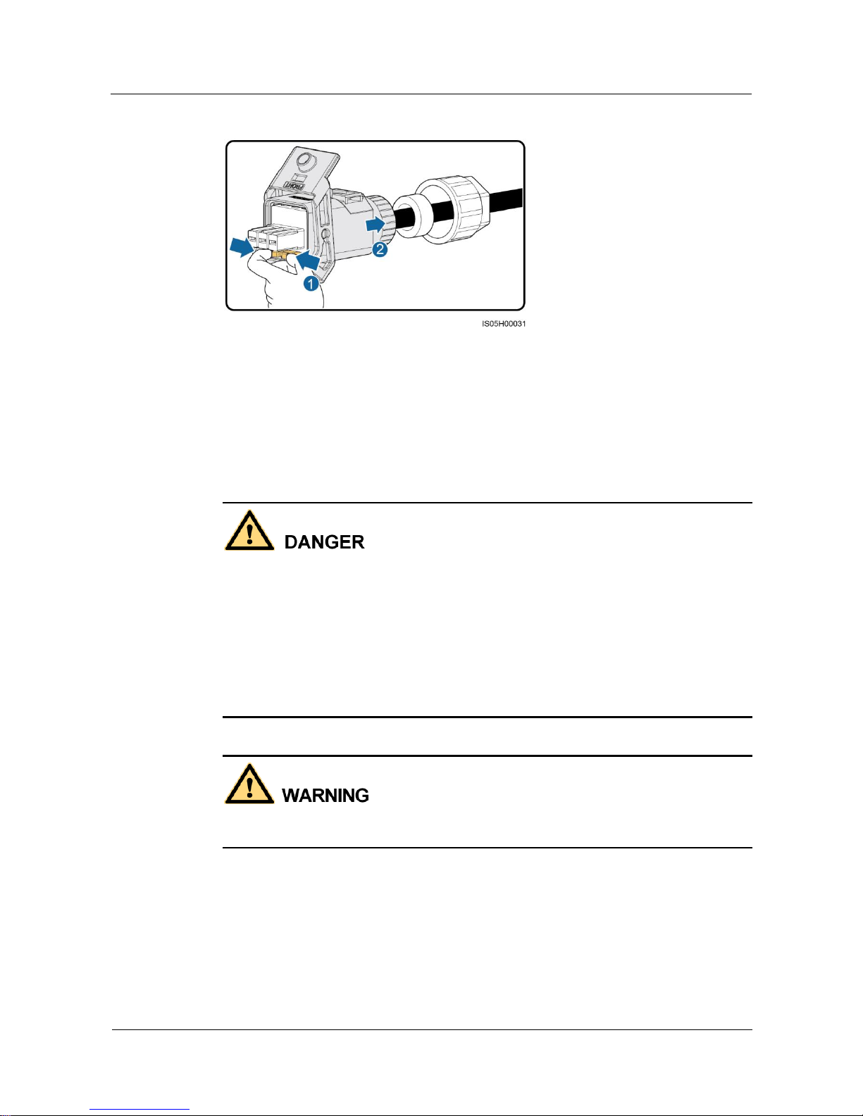
To remove the AC connector from the SUN2000L, perform the operations in reverse order.
Page 51
SUN2000L-(2KTL-5KTL)
User Manual
5 Electrical Connections
Issue 02 (2017-12-12)
Huawei Proprietary and Confidential
Copyright © Huawei Technologies Co., Ltd.
44
Figure 5-10 Removing a plug insert
5.4 Installing the DC Input Power Cable
Prerequisites
Before connecting the DC input power cable, ensure that the DC voltage is within the safe
range (lower than 60 V DC) and that the DC switch on the SUN2000L is OFF. Failing to
do so may result in electric shocks.
When the SUN2000L is operating, it is not allowed to work on DC circuit, such as
connecting or disconnecting a PV string or a PV module in a PV string. Failing to do so
may cause electric shocks.
If no PV string connects to the DC input terminals, do not remove the watertight cap from
the DC input terminals. Otherwise, the SUN2000L will not comply with its Ingress
Protection Rating.
Ensure that the following conditions are met. Otherwise, the SUN2000L will be damaged, or
even become a fire hazard.
Page 52
SUN2000L-(2KTL-5KTL)
User Manual
5 Electrical Connections
Issue 02 (2017-12-12)
Huawei Proprietary and Confidential
Copyright © Huawei Technologies Co., Ltd.
45
The open-circuit voltage of each PV string is always lower than or equal to 600 V DC.
The positive and negative terminals of a PV string connect to corresponding positive and
negative DC input terminals of the SUN2000L.
If polarity of the DC input power cable is reversed and the DC switch is ON, do not turn
off the DC switch immediately or unplug positive and negative connectors. Wait until the
solar irradiance declines at night and the PV string current reduces to below 0.5 A, and
then turn off the DC switch and remove the positive and negative connectors. Correct the
string polarity before reconnecting the string to the SUN2000L.
Since the output of the PV string connected to the SUN2000L cannot be grounded, ensure
that the PV module output is well insulated to ground.
During the installation of PV strings and SUN2000L, the positive or negative terminals of
PV strings may be grounded if power cables are not properly installed or routed. In this
case, an AC or DC short circuit may occur and damage the SUN2000L. This damage is not
covered under any warranty or service agreement.
Context
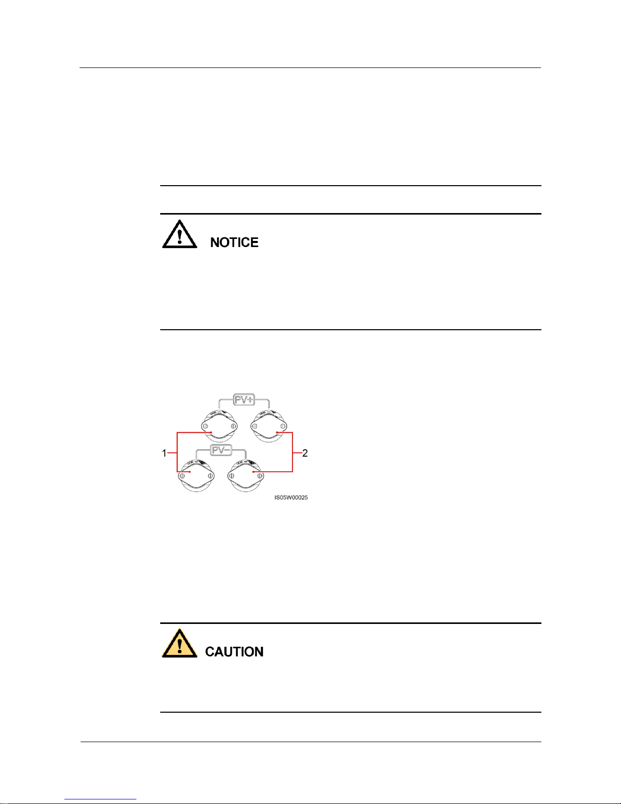
Figure 5-11 DC input terminals
(1) The first set of DC input terminals
(2) The second set of DC input terminals
Procedure
Step 1 Assemble the black positive and negative connectors.
Use the positive and negative metal terminals and DC connectors supplied with the
SUN2000L. Using incompatible positive and negative metal terminals and DC connectors
may result in serious consequences. The caused device damage is not covered under any
warranty or service agreement.
Page 53
SUN2000L-(2KTL-5KTL)
User Manual
5 Electrical Connections
Issue 02 (2017-12-12)
Huawei Proprietary and Confidential
Copyright © Huawei Technologies Co., Ltd.
46
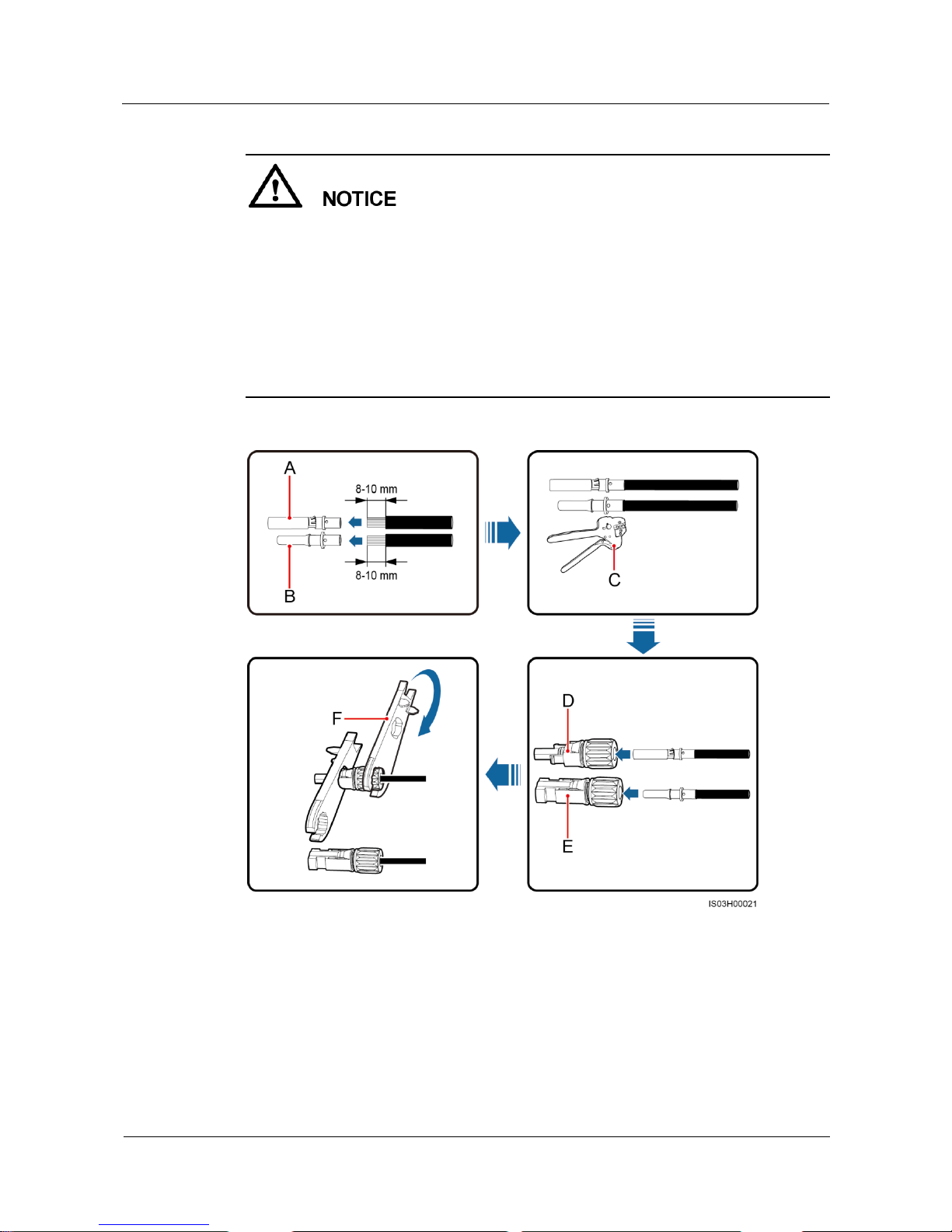
Cables with high rigidity, such as armored cables, are not recommended as DC input
power cables, because poor contact may be caused by the bending of the cables.
Before assembling DC input connectors, label the cable polarities correctly to ensure
correct cable connections.
After crimping the positive and negative metal terminals, pull the DC input power cables
back to ensure that they are connected securely.
Insert the crimped metal terminals of the positive and negative power cables into the
appropriate positive and negative connectors. Then pull back the DC input power cables to
ensure that they are connected securely.
Figure 5-12 Assembling a DC connector
(A) Positive metal
terminal
(B) Negative metal
terminal
(C) H4TC0001 crimping tool
(D) Positive connector
(E) Negative connector
(F) H4TW0001 open-end
wrench
Page 54
SUN2000L-(2KTL-5KTL)
User Manual
5 Electrical Connections
Issue 02 (2017-12-12)
Huawei Proprietary and Confidential
Copyright © Huawei Technologies Co., Ltd.
47
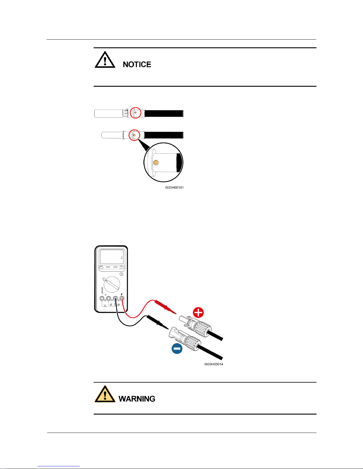
Ensure that the core wires can be seen through the hole on the terminal both before and after
the positive and negative metal terminals are crimped.
Figure 5-13 Observing core wires through the hole on the terminal
Step 2 Ensure that the DC input voltage of each PV string is within the specified range of the
SUN2000L using a multimeter and check that the polarities of DC input power cables are
correct.
Figure 5-14 Measuring the DC input voltage
Before performing Step 3, ensure that the DC switch is OFF.
Page 55
SUN2000L-(2KTL-5KTL)
User Manual
5 Electrical Connections
Issue 02 (2017-12-12)
Huawei Proprietary and Confidential
Copyright © Huawei Technologies Co., Ltd.
48
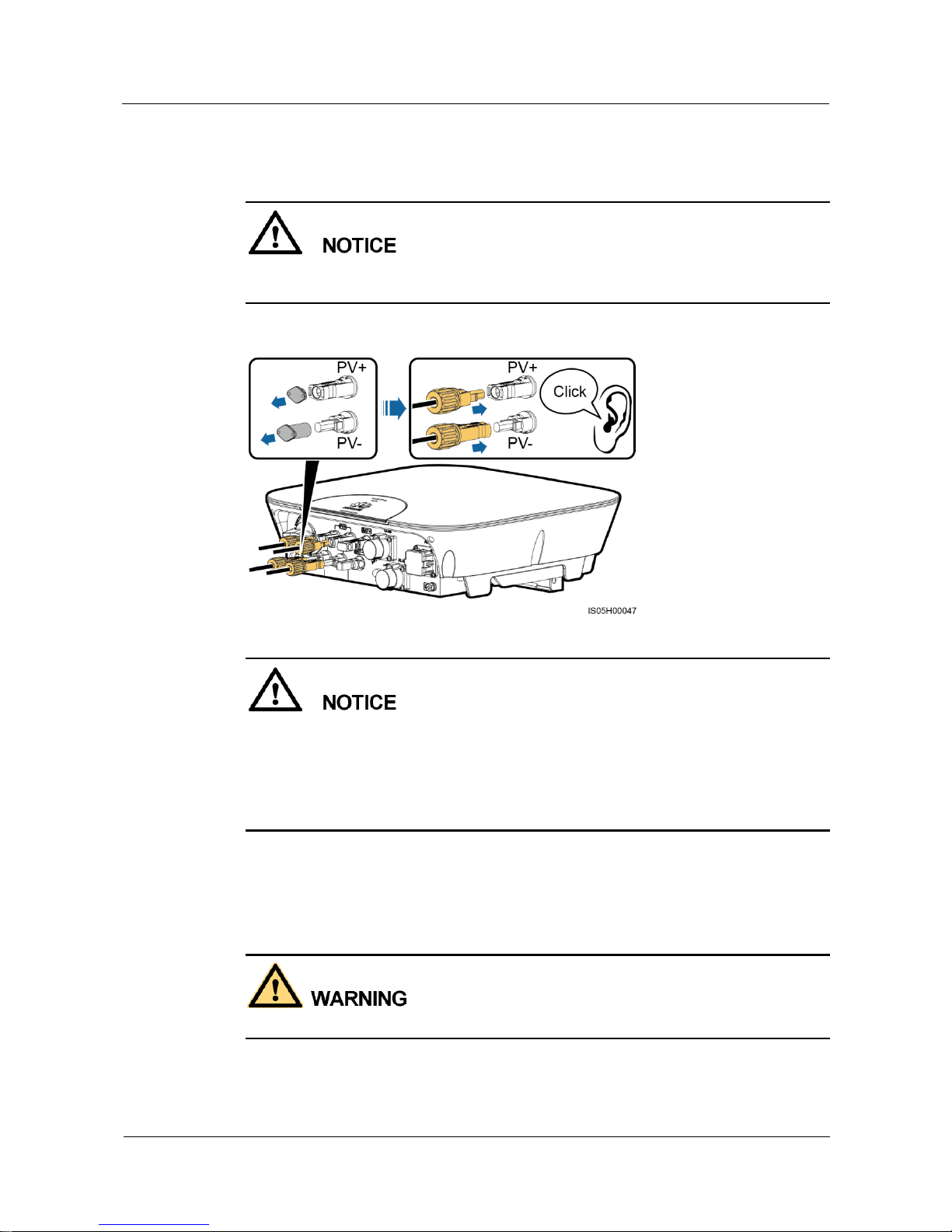
Step 3 Insert the positive and negative connectors into corresponding DC input terminals on the
SUN2000L.
After the positive and negative connectors snap into place, pull the DC input power cables
back to ensure that they are connected securely.
Figure 5-15 Connecting DC input power cables
If polarity of the DC input power cable is reversed and the DC switch is ON, do not turn off
the DC switch immediately or unplug positive and negative connectors. The device may be
damaged if you do not follow the instruction. This damage is not covered under any warranty
or service agreement. Wait until the solar irradiance declines at night and the PV string current
reduces to below 0.5 A, and then turn off the DC switch and remove the positive and negative
connectors. Correct the string polarity before reconnecting the string to the SUN2000L.
----End
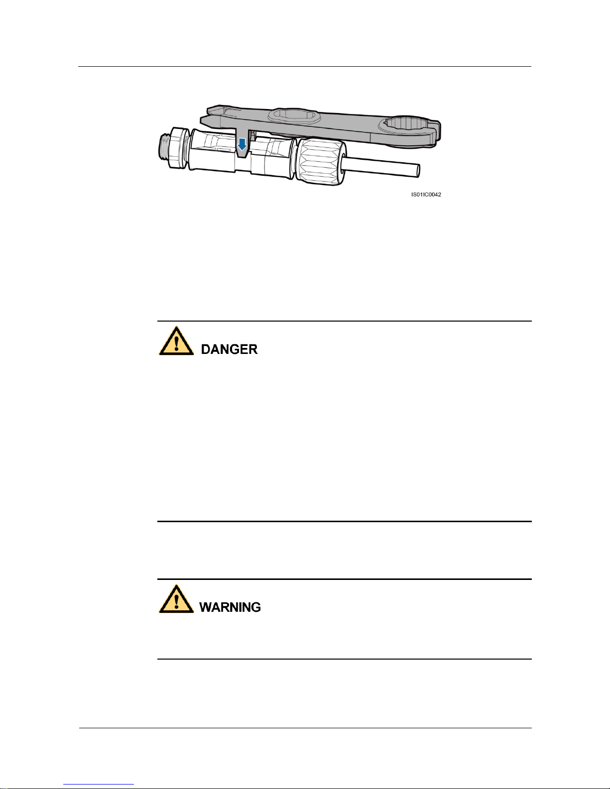
Follow-up Procedure
Before removing the positive and negative connectors, ensure that the DC switch is OFF.
To remove the positive and negative connectors from the SUN2000L, insert an open-end
wrench into the notch and press the wrench with an appropriate force.
Page 56
SUN2000L-(2KTL-5KTL)
User Manual
5 Electrical Connections
Issue 02 (2017-12-12)
Huawei Proprietary and Confidential
Copyright © Huawei Technologies Co., Ltd.
49
Figure 5-16 Removing a DC connector
5.5 Installing the Battery Cable
Prerequisites
Battery short circuits may cause personal injury. The high transient current generated by a
short circuit will release a surge of power and may even cause fire.
Do not connect or disconnect battery cables when the SUN2000L is running. Failing to do
so may cause electric shocks.
Before connecting battery cables, ensure that the DC switch on the SUN2000L and all the
switches connecting to the SUN2000L are OFF, and the SUN2000L has no residual
electricity. Otherwise, the high voltage of the SUN2000L and battery may result in electric
shocks.
If no battery connects to the SUN2000L, do not remove the watertight cap from the battery
terminal. Otherwise, the SUN2000L will not comply with its Ingress Protection Rating. If
a battery connects to the SUN2000L, set aside the watertight cap. Reinstall the watertight
cap immediately after removing the connector. The high voltage of the battery terminal
may result in electric shocks.
A battery switch can be configured between the SUN2000L and the battery to ensure that the
SUN2000L can be safely disconnected from the battery.
Do not connect any load between the SUN2000L and the battery.
Ensure that the following conditions are met. Otherwise, the SUN2000L will be damaged, or
even become a fire hazard.
Page 57
SUN2000L-(2KTL-5KTL)
User Manual
5 Electrical Connections
Issue 02 (2017-12-12)
Huawei Proprietary and Confidential
Copyright © Huawei Technologies Co., Ltd.
50
The battery open-circuit voltage should always be lower than or equal to 600 V DC.
The battery cable is connected correctly. That is, the positive and negative terminals of the
battery connect to the positive battery terminal and negative battery terminal on the
SUN2000L respectively.
During the installation of the SUN2000L and battery, the positive or negative terminal of
the battery will be short-circuited to ground if power cables are not installed or routed as
required. In this case, an AC or DC short circuit may occur and damage the SUN2000L.
This damage is not covered under any warranty or service agreement.
The cable between the battery and the SUN2000L should be less than or equal to 10
meters, and within 5 meters is recommended.
Procedure
Step 1 Assemble the blue positive and negative connectors by following the instructions in 5.4
Installing the DC Input Power Cable.
The battery voltage will result in serious injury. Use dedicated insulation tools to connect
cables.
Ensure that cables are correctly connected between the battery terminal and the battery
switch, and between the battery switch and the SUN2000L battery terminal.
Cables with high rigidity, such as armored cables, are not recommended, because poor contact
may be caused by the bending of the cables.
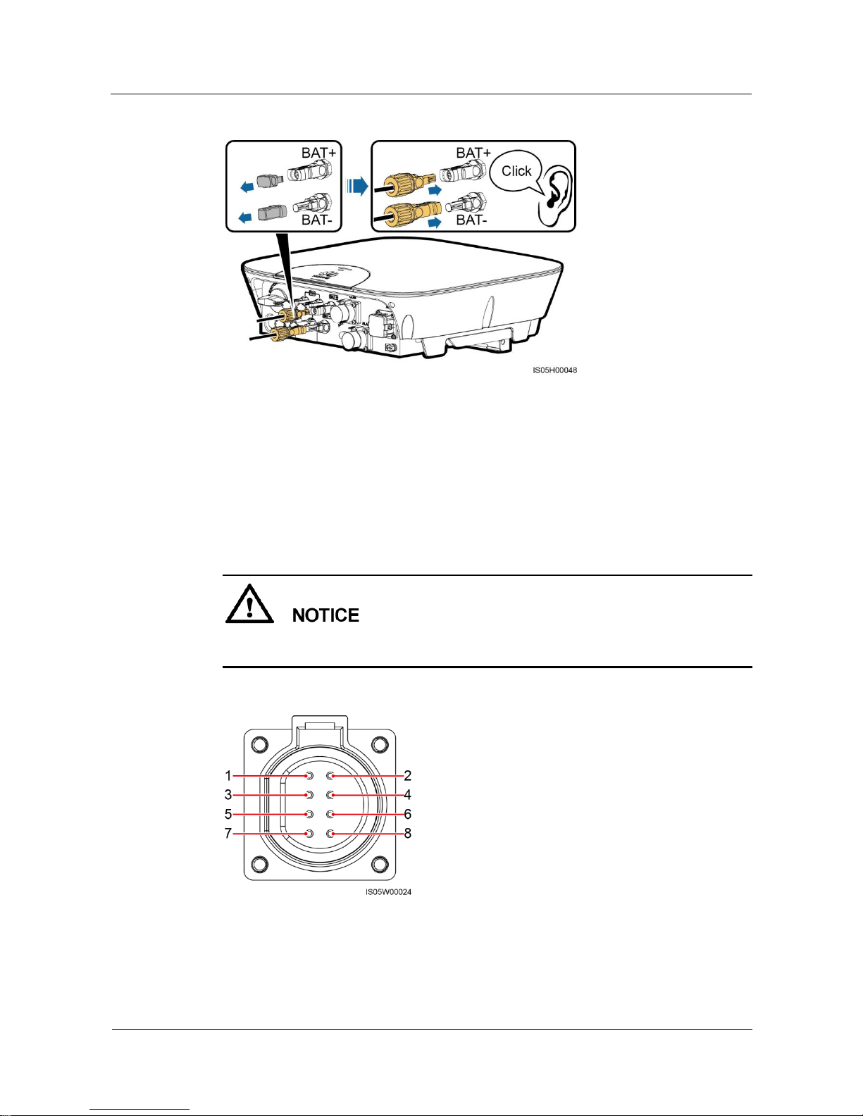
Step 2 Insert the positive and negative connectors into corresponding battery terminals on the
SUN2000L.
After the positive and negative connectors snap into place, pull test to the battery cables is
recommended.
Page 58
SUN2000L-(2KTL-5KTL)
User Manual
5 Electrical Connections
Issue 02 (2017-12-12)
Huawei Proprietary and Confidential
Copyright © Huawei Technologies Co., Ltd.
51
Figure 5-17 Connecting battery cables
----End
5.6 Installing the Signal Cable
Context
When laying out signal cables, separate them from power cables to avoid strong signal
interference sources.
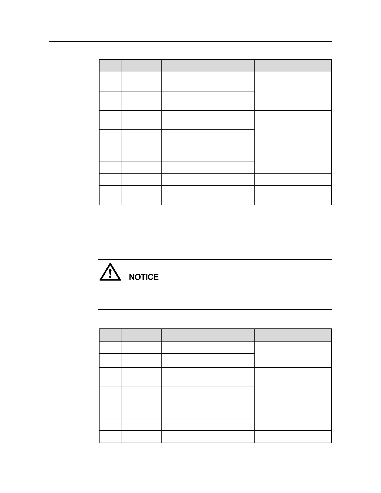
Figure 5-18 COM and ALARM ports
The COM port provides two RS485 communications ports and one enable signal port to
connect to power collectors, batteries, and so on.
Page 59
SUN2000L-(2KTL-5KTL)
User Manual
5 Electrical Connections
Issue 02 (2017-12-12)
Huawei Proprietary and Confidential
Copyright © Huawei Technologies Co., Ltd.
52
Table 5-3 COM port pin definitions
No.
Label
Definition
Description
1
485B1
RS485B, RS485 differential
signal–
Reserved, can connect to the
RS485 signal port on the
power collector.
2
485A1
RS485A, RS485 differential
signal+
3
485B2
RS485B, RS485 differential
signal–
Reserved, can connect to the
RS485 signal port and
enable signal port on a
battery.
4
485A2
RS485A, RS485 differential
signal+
5
EN–
Enable signal–
6
EN+
Enable signal+
7
N/A
N/A
N/A
8
PE
Shielding ground
Connects to the shield layer
of the cable.
The ALARM port provides an alarm signal port to connect to an alarm beacon, which reminds
the user to handle the Low Insulation Resistance, Abnormal Residual Current, or Faulty
Residual Current Sensor alarm. The ALARM port reserves an RS485/12 V signal port.
The alarm beacon should be installed within 2 meters away from the SUN2000L.
The Faulty Residual Current Sensor alarm is the Abnormal Device alarm with a cause ID
of 5.
Table 5-4 ALARM port pin definitions
No.
Label
Definition
Description
1
ALARM–
Alarm signal–
Reserved, can connect to the
power port on an alarm
beacon
2
ALARM+
Alarm signal+
3
485B3
RS485B, RS485 differential
signal–
Reserved RS485/12 V
signal port, output power of
the 12 V power supply ≤ 3
W
4
485A3
RS485A, RS485 differential
signal+
5
12 V–
Negative of the 12 V power supply
6
12 V+
Positive of the 12 V power supply
7
N/A
N/A
N/A
Page 60
SUN2000L-(2KTL-5KTL)
User Manual
5 Electrical Connections
Issue 02 (2017-12-12)
Huawei Proprietary and Confidential
Copyright © Huawei Technologies Co., Ltd.
53
No.
Label
Definition
Description
8
PE
Shielding ground
Connects to the shield layer
of the cable.
Procedure
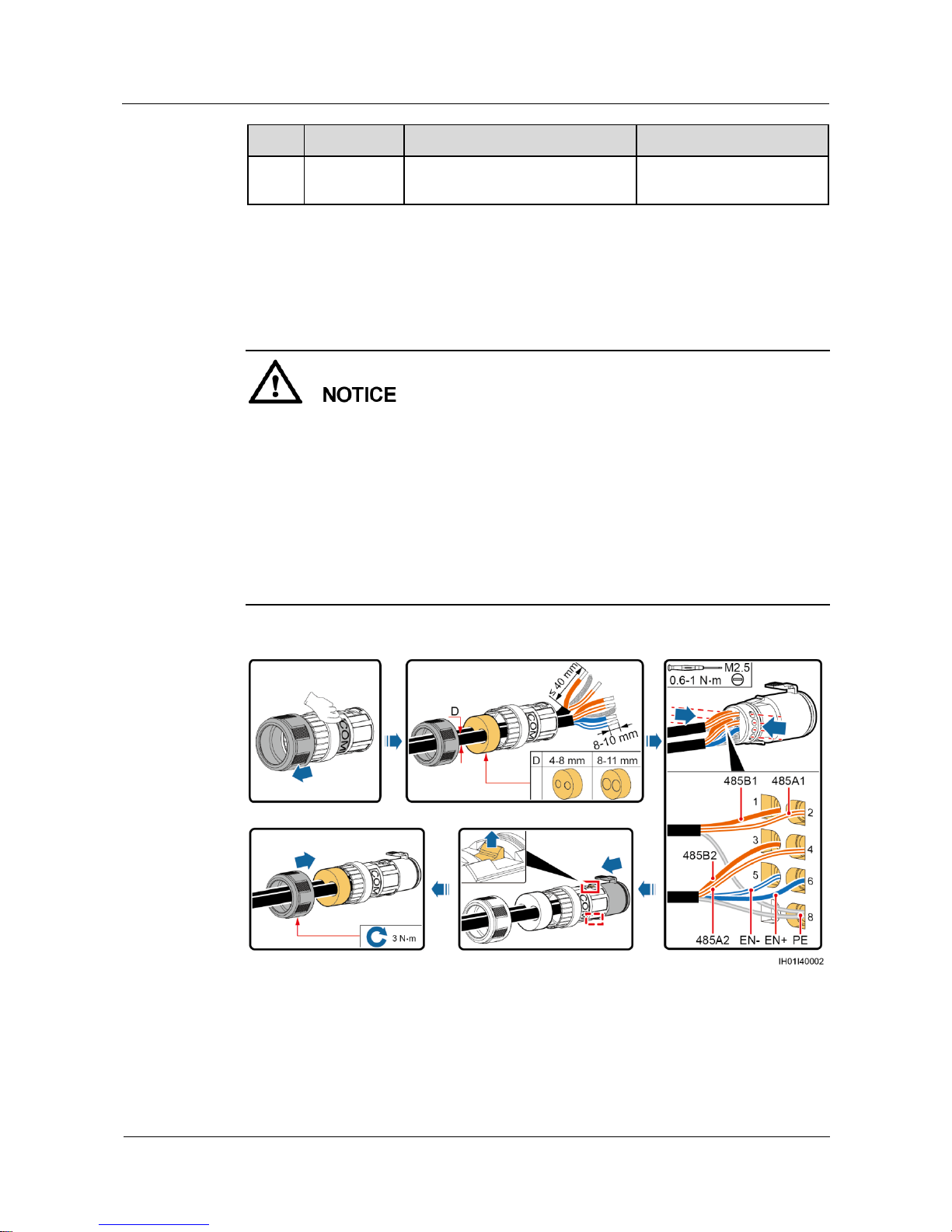
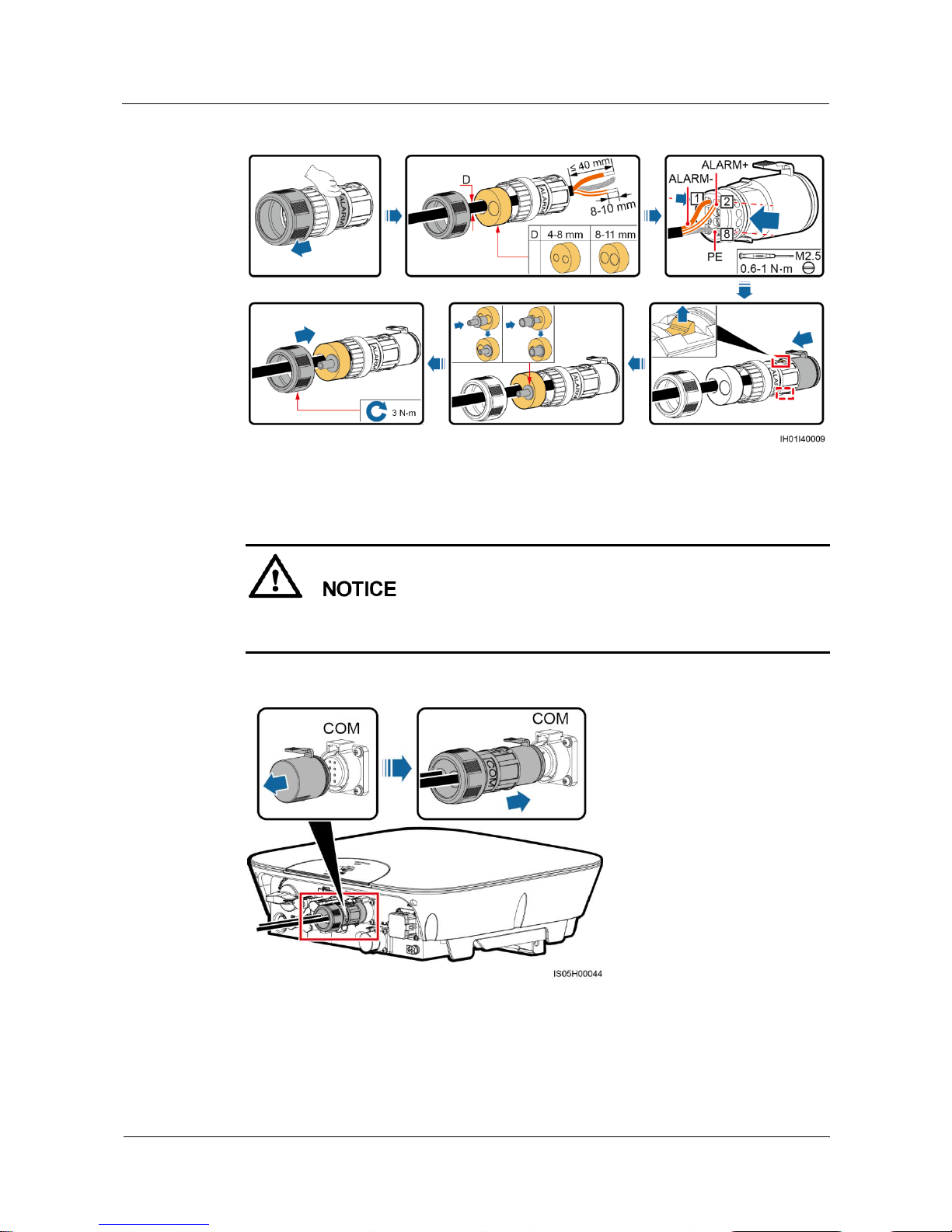
Step 1 Connect signal cables to appropriate signal connectors.
The protection layer of the cable is in the connector. Surplus core wires are cut off from
the protection layer.
Ensure that the exposed core wire is totally inserted into the cable hole.
Ensure that the signal cables are connected securely.
Ensure that the cable is not twisted.
If a connector needs to connect to only one signal cable, block the unused cable hole on
the seal using a cap and tighten the cable gland.
If a connector needs to connect to two signal cables, ensure that the cables have the same
outer diameter.
Figure 5-19 Assembling a signal connector (COM port)
Page 61
SUN2000L-(2KTL-5KTL)
User Manual
5 Electrical Connections
Issue 02 (2017-12-12)
Huawei Proprietary and Confidential
Copyright © Huawei Technologies Co., Ltd.
54
Figure 5-20 Assembling a signal connector (ALARM port)
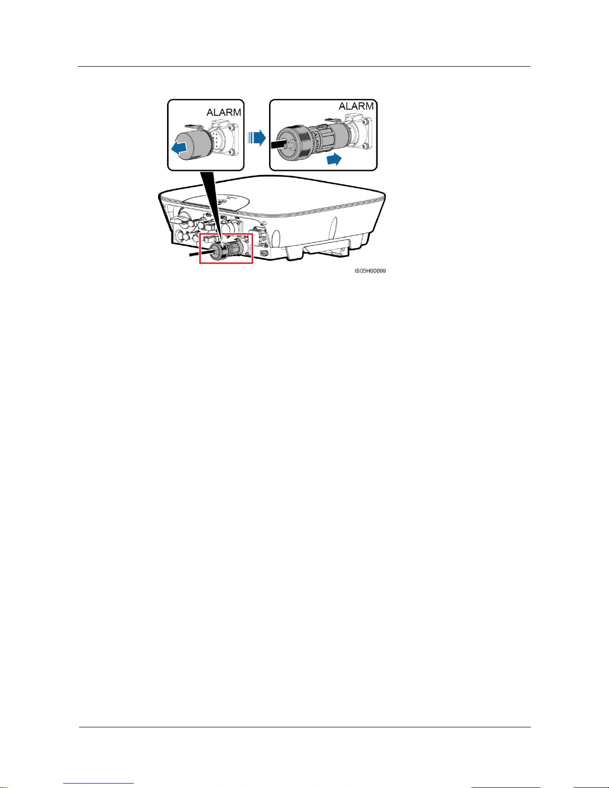
Step 2 Connect the signal connector to the corresponding port.
Do not confuse the connectors to the COM port and ALARM port.
Ensure that the signal connector is connected securely.
Figure 5-21 Securing a connector (COM port)
Page 62
SUN2000L-(2KTL-5KTL)
User Manual
5 Electrical Connections
Issue 02 (2017-12-12)
Huawei Proprietary and Confidential
Copyright © Huawei Technologies Co., Ltd.
55
Figure 5-22 Securing a connector (ALARM port)
----End
Page 63
SUN2000L-(2KTL-5KTL)
User Manual
6 System Commissioning
Issue 02 (2017-12-12)
Huawei Proprietary and Confidential
Copyright © Huawei Technologies Co., Ltd.
56
6 System Commissioning
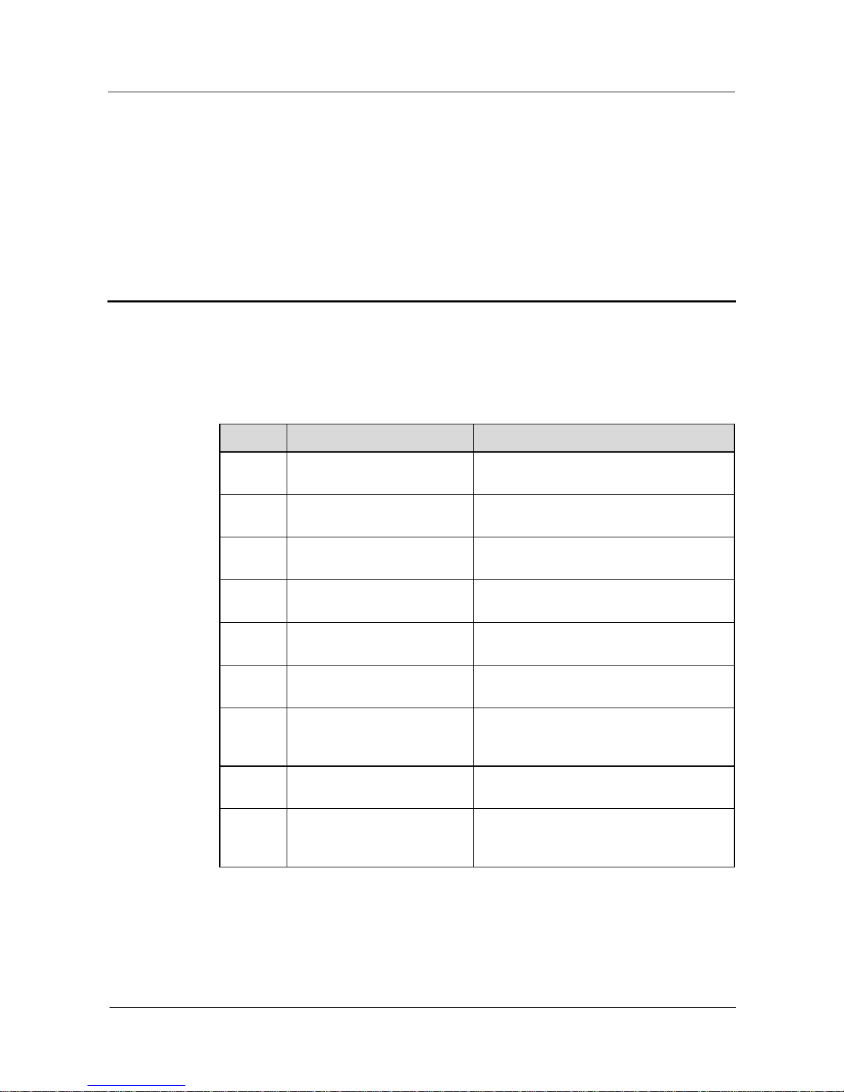
6.1 Checking Before Power-On
Table 6-1 Installation checklist
No.
Check Item
Acceptance Criteria
1
SUN2000L installation
The SUN2000L is installed correctly,
securely, and reliably.
2
WiFi antenna installation
The WiFi antenna is installed correctly,
securely, and reliably.
3
Cable layout
Cables are routed properly as required by the
customer.
4
Cable tie
Cable ties are secured evenly and no burr
exists.
5
Grounding
The ground cable is connected correctly,
securely, and reliably.
6
DC switch
The DC switch and all the switches
connecting to the SUN2000L are OFF.
7
Cable connections
The AC output power cable, DC input power
cable, battery cable, and signal cable are
connected correctly, securely, and reliably.
8
Unused terminals and ports
Unused terminals and ports are locked by
watertight caps.
9
Installation environment
The installation space is proper, and the
installation environment is clean and tidy,
without foreign matter.
Page 64
SUN2000L-(2KTL-5KTL)
User Manual
6 System Commissioning
Issue 02 (2017-12-12)
Huawei Proprietary and Confidential
Copyright © Huawei Technologies Co., Ltd.
57
6.2 Powering On the System
Prerequisites
Before turning on the AC switch between the SUN2000L and the power grid, check that the
AC voltage on the power grid side of the AC switch is within the specified range.
If the DC is on and the AC is off, the SUN2000L reports a Grid Failure alarm. The
SUN2000L starts normally only after the fault is rectified.
If the AC is on and the battery is off, the SUN2000L reports a Battery Abnormal alarm.
If the SUN2000L is connected to the battery, after turning on the AC switch:
If the DC switch is turned on within 1 minute, the SUN2000L will run properly in
grid-tied mode.
If the DC switch is not turned on within 1 minute, the SUN2000L will enter the nighttime
grid-tied mode. Then, after the DC switch is turned on, the SUN2000L will shut down and
then restart to run in grid-tied mode.
Procedure
Step 1 If a battery connects to the battery port, turn off the battery Auxiliary Power ON/OFF switch,
and then turn off the battery Circuit Breaker switch.
Step 2 Turn on the AC switch between the SUN2000L and the power grid.
Step 3 Turn on the DC switch between the PV string and the SUN2000L if there is any.
Step 4 Turn on the DC switch at the bottom of the SUN2000L.
Step 5 Set the SUN2000L parameters on the app. For details, see 7 Operations on the Local
FusionHome App.
Step 6 (Optional) Measure the temperatures at DC terminals and battery terminals using a point-test
thermometer.
Under normal operation conditions of the SUN2000L, the temperature rise at DC terminals
should remain below 30°C at all time.
Step 7 Observe the LEDs to check the SUN2000L operating status.
Page 65
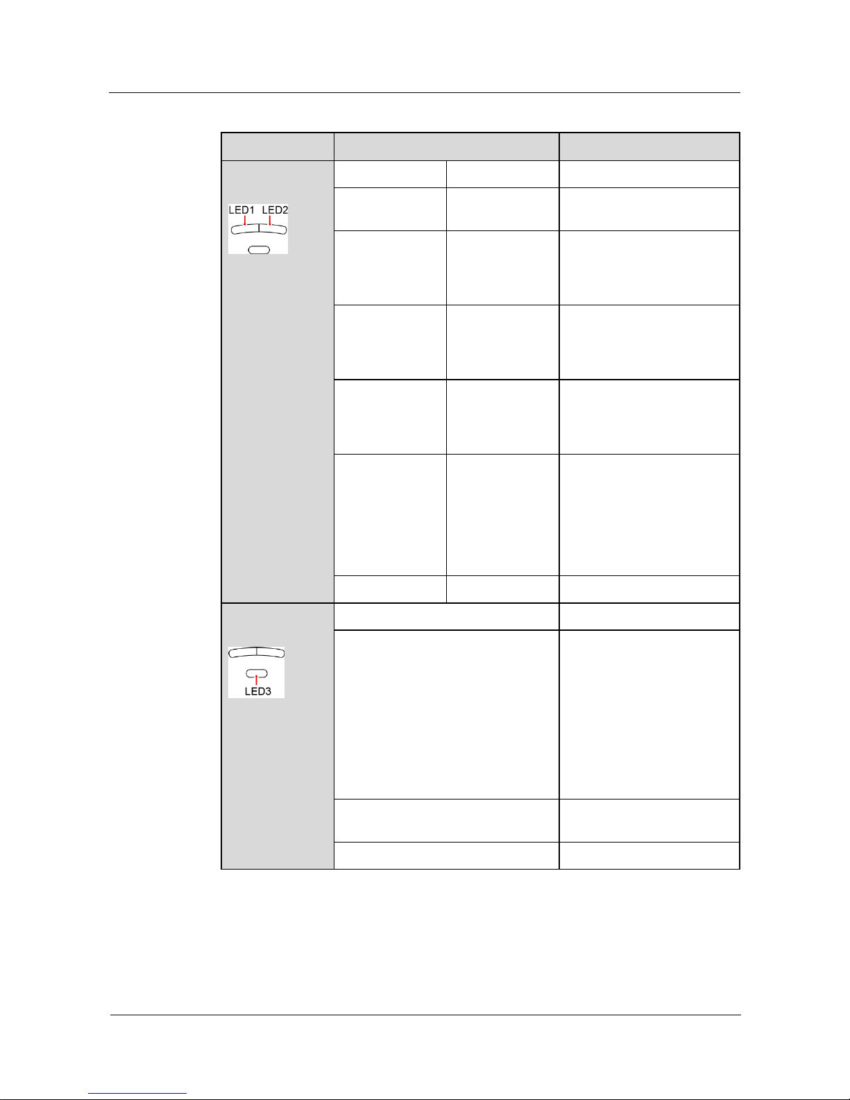
SUN2000L-(2KTL-5KTL)
User Manual
6 System Commissioning
Issue 02 (2017-12-12)
Huawei Proprietary and Confidential
Copyright © Huawei Technologies Co., Ltd.
58
Table 6-2 LED description
Type
Status
Meaning
Running
indication
LED 1
LED 2
N/A
Steady green
Steady green
The SUN2000L is exporting
power to the power grid.
Blinking green at
long intervals (on
for 1s and then
off for 1s)
Off
The DC is on and the AC is
off.
Off
Blinking green at
long intervals (on
for 1s and then
off for 1s)
The DC is off and the AC is
on.
Blinking green at
long intervals (on
for 1s and then
off for 1s)
Blinking green at
long intervals (on
for 1s and then
off for 1s)
The DC is on, the AC is on,
and the SUN2000L is not
exporting power to the power
grid.
Off
Off
Both the DC and AC are off,
or the SUN2000L is in Low
Power Consumption mode.
Low Power Consumption
mode means that the
monitoring system of the
SUN2000L hibernates.
Steady red
Steady red
The SUN2000L is faulty.
Communicatio
n indication
LED 3
N/A
Blinking green at short intervals (on
for 0.2s and then off for 0.2s)
Communicating
(Communicating refers to that
the communication with the
upper-level management unit
is in progress. However, if a
mobile phone accesses the
SUN2000L, the LED
indicates the "mobile phone
access status: blinking green
at long intervals" first.)
Blinking green at long intervals (on
for 1s and then off for 1s)
The mobile phone has
connected to the SUN2000L.
Off
Others
----End
Page 66
SUN2000L-(2KTL-5KTL)
User Manual
6 System Commissioning
Issue 02 (2017-12-12)
Huawei Proprietary and Confidential
Copyright © Huawei Technologies Co., Ltd.
59
6.3 Powering Off the System
Context
After the SUN2000L powers off, the remaining electricity and heat may still cause electric
shocks and body burns. Therefore, put on protective gloves and begin servicing the
SUN2000L 5 minutes after the power-off.
If the SUN2000L is connected to the battery, ensure that a shutdown command is sent
from the app. Power off the system after the SUN2000L has shut down. If no shutdown
command is sent from the app, the SUN2000L will shut down after the power grid is
powered off. Then, the SUN2000L will wait for 1 minute and restart (not grid-tied) to
charge the battery, which poses the risk of turning off the DC switch with power.
Procedure
Step 1 Send a shutdown command from the app. Perform operations by referring to 7.4.3.5 Starting
or Shutting Down the SUN2000L if you log in as installer; perform operations by referring to
7.5.6 Settings if you log in as user.
Step 2 Turn off the AC switch between the SUN2000L and the power grid.
Step 3 Turn off the DC switch at the bottom of the SUN2000L.
Step 4 Turn off the DC switch between the PV string and the SUN2000L if there is any.
Step 5 If a battery connects to the battery port, turn off the battery switch.
----End
Page 67
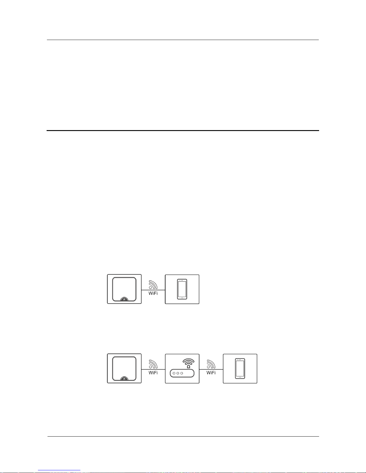
SUN2000L-(2KTL-5KTL)
User Manual
7 Operations on the Local FusionHome App
Issue 02 (2017-12-12)
Huawei Proprietary and Confidential
Copyright © Huawei Technologies Co., Ltd.
60
7 Operations on the Local FusionHome App
7.1 App Overview
Function
The local FusionHome app (app for short) is a mobile phone app that locally communicates
with the SUN2000L over WiFi to allow for querying alarms, configuring parameters, and
performing routine maintenance, and commissioning.
Connection Method
After the DC or AC side of the SUN2000L is energized, the app can connect to the
SUN2000L in either of the following ways:
Method 1: The mobile phone connects to the SUN2000L directly.
Figure 7-1 Mobile phone connecting to the SUN2000L directly
Method 2: The mobile phone connects to the SUN2000L over a router. Do not use this
method for the first login and ensure that the SUN2000L has connected to the router.
Figure 7-2 Mobile phone connecting to the SUN2000L over a router
Page 68
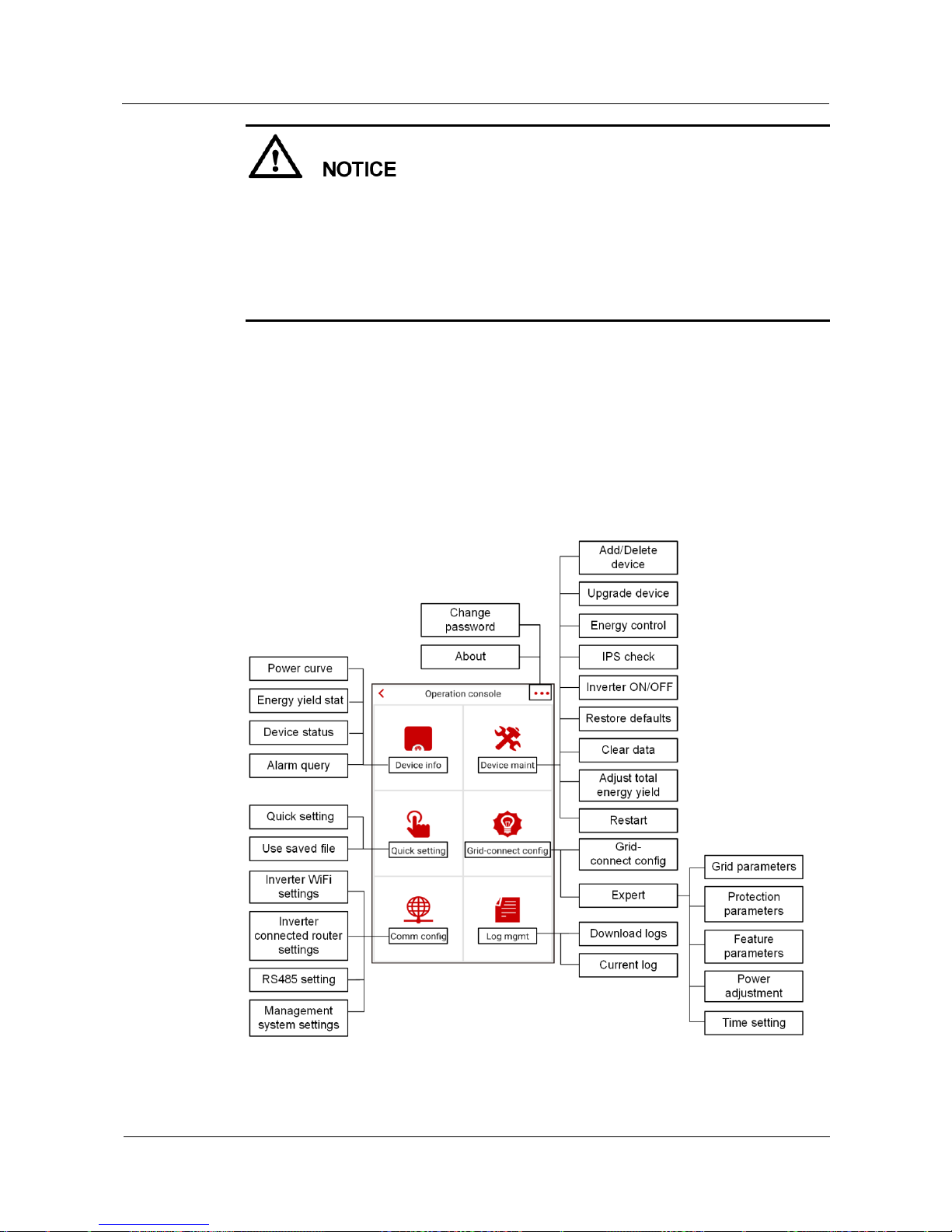
SUN2000L-(2KTL-5KTL)
User Manual
7 Operations on the Local FusionHome App
Issue 02 (2017-12-12)
Huawei Proprietary and Confidential
Copyright © Huawei Technologies Co., Ltd.
61
Mobile phone operating system: Android 4.4 or later, iOS 8.0 or later.
Recommended brands: Huawei, Samsung, and iPhone
The mobile phone supports the access to the Internet over a web browser.
The mobile phone supports WiFi.
The router supports WiFi (IEEE 802.11 b/g/n, 2.4 GHz) and the WiFi signal reaches the
SUN2000L.
Disclaimer
The app screen snapshots provided in this document correspond to FusionHome 2.1.11.201.
The figures are for reference only.
User Operation Permissions
The app users are classified into the installer and user.
Figure 7-3 Operation permissions of the installer
Page 69
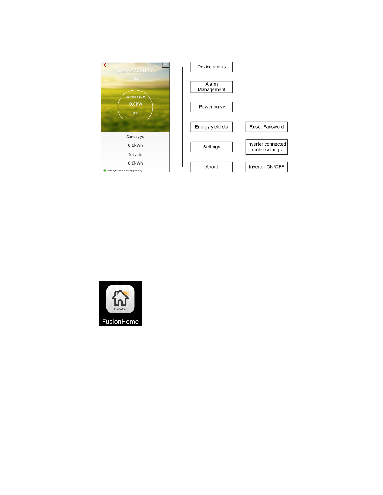
SUN2000L-(2KTL-5KTL)
User Manual
7 Operations on the Local FusionHome App
Issue 02 (2017-12-12)
Huawei Proprietary and Confidential
Copyright © Huawei Technologies Co., Ltd.
62
Figure 7-4 Operation permissions of the user
7.2 Downloading and Installing the App
Search for FusionHome from the following app stores, download the installation package,
and install the FusionHome app by following the instructions.
Google Play (Android)
Huawei App Store (Android)
App Store (iOS)
After the app is installed, the FusionHome icon is displayed on the home screen.
7.3 Connecting to a SUN2000L WiFi Network
Prerequisites
The DC or AC side of the SUN2000L has been energized.
The WiFi function is enabled on the mobile phone.
When connecting the SUN2000L to the app directly, keep the mobile phone within 5
meters of the SUN2000L with no barrier in between to ensure the communication quality
between them.
When connecting the SUN2000L to the app over a router, ensure that the mobile phone
and SUN2000L are in the WiFi coverage of the router and the SUN2000L has connected
to the router.
Page 70
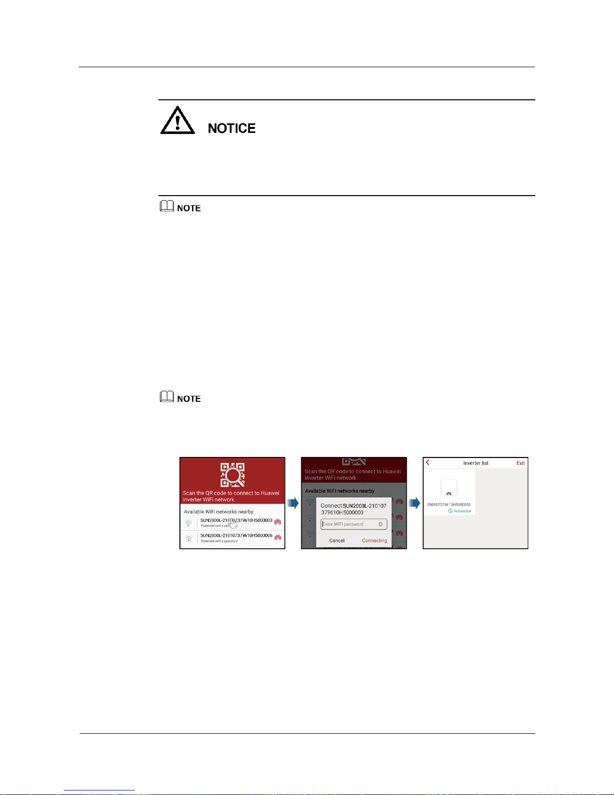
SUN2000L-(2KTL-5KTL)
User Manual
7 Operations on the Local FusionHome App
Issue 02 (2017-12-12)
Huawei Proprietary and Confidential
Copyright © Huawei Technologies Co., Ltd.
63
The way of connecting the SUN2000L to the router is as follows:
The installer taps Quick setting (see 7.4.4 Quick Setting for details) or Comm config (see
7.4.6 Comm Config for details).
The user taps Set (see 7.5.6 Settings for details).
If the WiFi signal is weak, you will be prompted to try again multiple times. Follow the instructions.
To exit the app, tap Exit on the Inverter list screen.
Procedure on the Android System
The app allows for connecting to the SUN2000L in the following two ways. Select either way
based on site requirements. After the connection succeeds, the Inverter list screen is
displayed. If connecting to the SUN2000L or router WiFi network from the app fails, try to
connect to the WiFi network from your mobile phone. To connect to the router over WiFi
from the mobile phone system, ensure that you have logged out of the app.
Method 1: The mobile phone connects to the SUN2000L directly.
Run the app, tap the WiFi name corresponding to the SUN2000L, and enter the WiFi
password to connect to the WiFi network. Use the initial password Changeme upon first
login. To ensure account security, change the password immediately after login.
The name of the connected SUN2000L WiFi network is represented by SUN2000L-its serial number
(SN). The SN is available on the label attached to the side of the SUN2000L.
Figure 7-5 Mobile phone connecting to the SUN2000L directly
If you log in for the first time and the initial SUN2000L WiFi password is not changed,
you can scan the WiFi login QR code on the side of the SUN2000L to connect to the
SUN2000L WiFi network.
Page 71
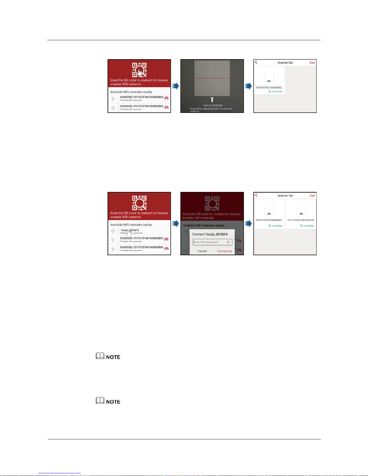
SUN2000L-(2KTL-5KTL)
User Manual
7 Operations on the Local FusionHome App
Issue 02 (2017-12-12)
Huawei Proprietary and Confidential
Copyright © Huawei Technologies Co., Ltd.
64
Figure 7-6 Scanning the QR code to connect the mobile phone to the SUN2000L directly
Method 2: The mobile phone connects to the SUN2000L over a router. Do not use this
method for the first login and ensure that the SUN2000L has connected to the router.
Run the app. If the SUN2000L WiFi network has connected to the router, tap the WiFi
name corresponding to the router for connection. After the connection succeeds, the
Inverter list screen displays all the Huawei SUN2000Ls that have connected to the
router.
Figure 7-7 Mobile phone connecting to the SUN2000L over a router
----End
Procedure on the iOS System
The app allows for connecting to the SUN2000L in the following two ways. Select either way
based on site requirements. After the connection succeeds, the Inverter list screen is
displayed.
Method 1: The mobile phone connects to the SUN2000L directly.
a. Choose Settings > WLAN on your mobile phone and tap the WiFi name
corresponding to the SUN2000L.
The name of the connected SUN2000L WiFi network is represented by SUN2000L-its serial number
(SN). The SN is available on the label attached to the side of the SUN2000L.
b. Enter the SUN2000L WiFi password for connection. Use the initial password
Changeme upon first login. To ensure account security, change the password
immediately after login.
If you log in for the first time and the initial SUN2000L WiFi password is not changed, you can run the
app, tap Scan, and scan the WiFi login QR code on the side of the SUN2000L to obtain the WiFi login
password.
Page 72
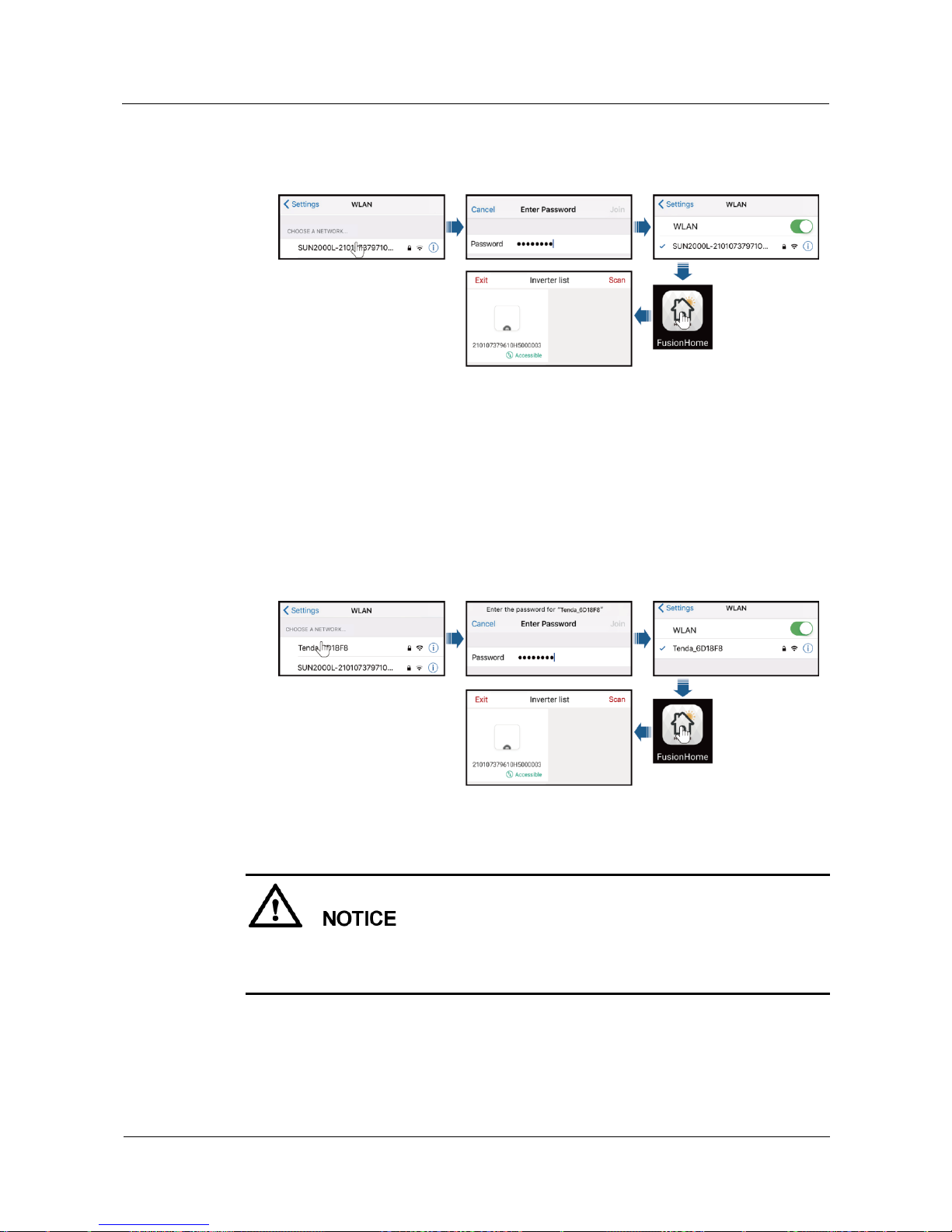
SUN2000L-(2KTL-5KTL)
User Manual
7 Operations on the Local FusionHome App
Issue 02 (2017-12-12)
Huawei Proprietary and Confidential
Copyright © Huawei Technologies Co., Ltd.
65
c. Run the app. After the connection succeeds, the Inverter list screen is displayed.
Figure 7-8 Mobile phone connecting to the SUN2000L directly
Method 2: The mobile phone connects to the SUN2000L over a router. Do not use this
method for the first login and ensure that the SUN2000L has connected to the router.
a. If the SUN2000L WiFi network has connected to the router, Choose Settings >
WLAN on the mobile phone and tap the WiFi name corresponding to the router.
b. Enter the router WiFi password for connection.
c. Run the app. The Inverter list screen displays all the Huawei SUN2000Ls that
have connected to the router.
Figure 7-9 Mobile phone connecting to the SUN2000L over a router
----End
The following text describes the operations on Android screens. The operations on iOS
screens are the same as those on Android screens, except that the screens are somewhat
different. The actual screens prevail.
Page 73
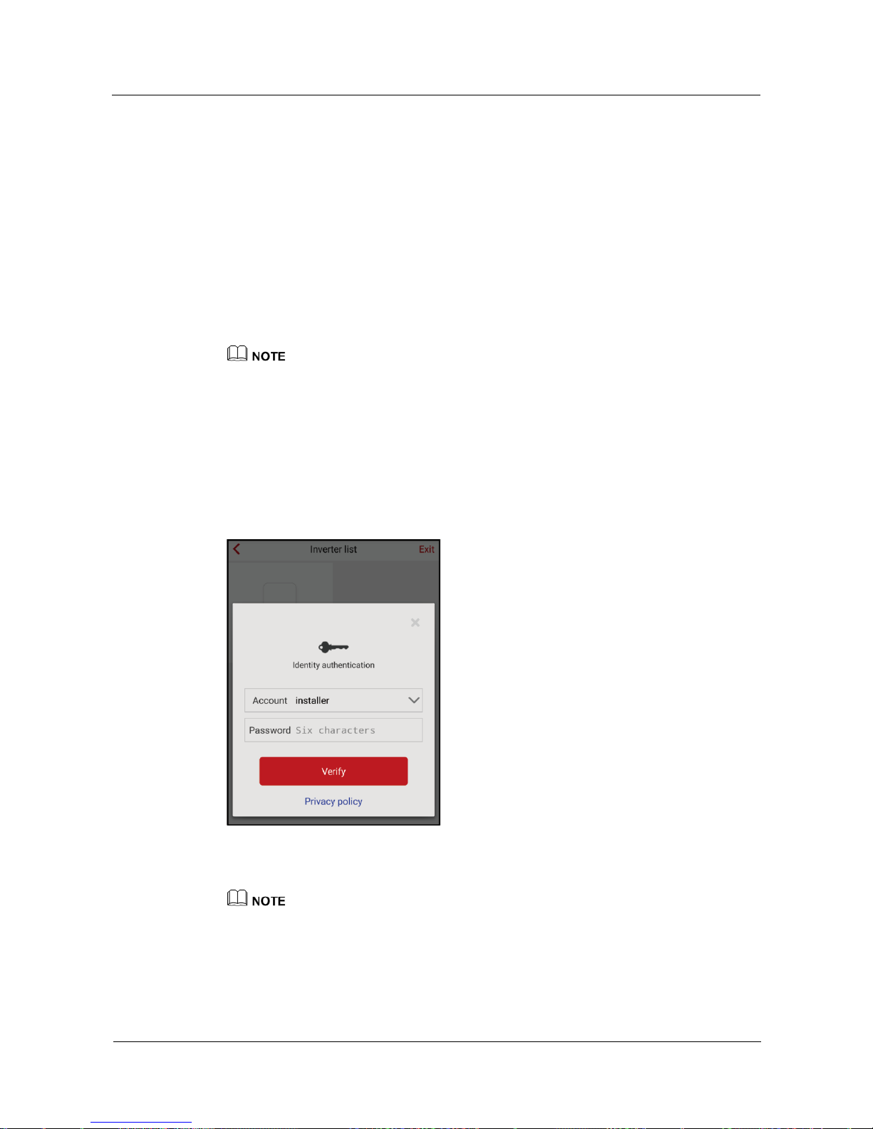
SUN2000L-(2KTL-5KTL)
User Manual
7 Operations on the Local FusionHome App
Issue 02 (2017-12-12)
Huawei Proprietary and Confidential
Copyright © Huawei Technologies Co., Ltd.
66
7.4 App Operations by the Installer
7.4.1 Logging In to the App
Prerequisites
The corresponding SUN2000L is displayed on the Inverter list screen.
Procedure
Step 1 On the Inverter list screen, tap the corresponding SUN2000L, select installer, enter the
password, and log in to the app.
The name of the connected SUN2000L is represented by its serial number (SN), which is available
on the SN label attached to the side of the SUN2000L.
The login password is the same as that for the SUN2000L connected to the app and is used only
when the SUN2000L connects to the app.
The initial password is 00000a. Use the initial password upon first login. To ensure account security,
change the password immediately after login.
If you enter wrong passwords for five consecutive times and the interval between two consecutive
passwords is within 2 minutes, your account will be locked out for 5 minutes.
Figure 7-10 Identity authentication
Step 2 If you log in successfully, the Quick setting or Operation console screen is displayed.
The Quick setting screen is displayed only when the SUN2000L connects to the app for the first
time or the factory defaults of the SUN2000L are restored.
If you do not follow the deployment wizard, the Quick setting screen is still displayed when you log
in next time.
To exit the deployment, press the Back button on the mobile phone or tap Exit on the screen. To
enter the Quick setting screen again, choose Quick setting from the Operation console screen.
Page 74
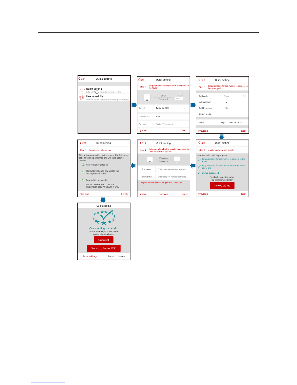
SUN2000L-(2KTL-5KTL)
User Manual
7 Operations on the Local FusionHome App
Issue 02 (2017-12-12)
Huawei Proprietary and Confidential
Copyright © Huawei Technologies Co., Ltd.
67
The Quick setting screen provides two deployment modes. Select either of them based on site
requirements.
Method 1: quick setting
Figure 7-11 Quick setting
Page 75
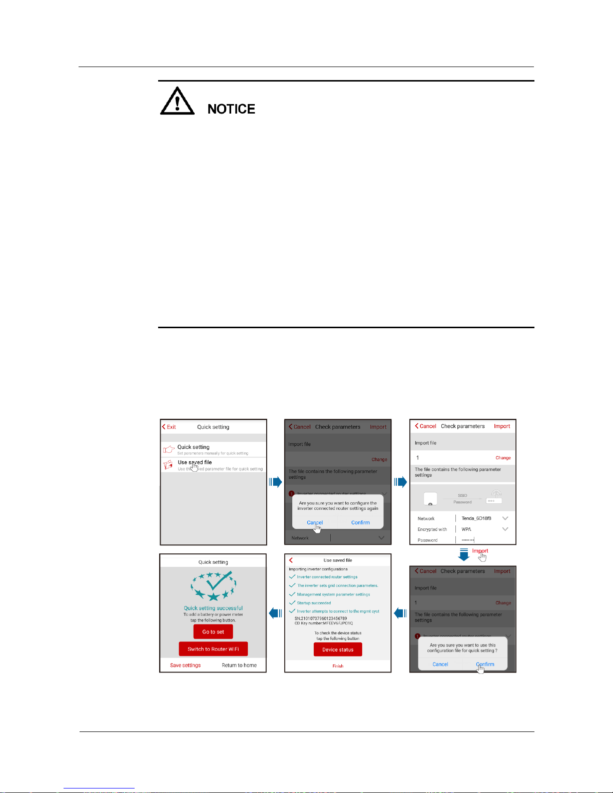
SUN2000L-(2KTL-5KTL)
User Manual
7 Operations on the Local FusionHome App
Issue 02 (2017-12-12)
Huawei Proprietary and Confidential
Copyright © Huawei Technologies Co., Ltd.
68
Set the grid code that applies to the country or region where the PV plant is located and the
SUN2000L model.
If there is no need to connect to the router or management system, skip relevant steps.
After the management system is successfully connected, the SUN2000L will report the SN
and installer registration code. If the connection fails, another connection attempt will start
after 10 seconds. The installer registration code is generated by the SUN2000L
automatically and is used for the installer to register with the management system and
manage the inverter.
For the operations about how to add devices, see 7.4.3.1 Adding/Deleting Devices.
After quick setting is complete, tap Switch to Router WiFi to switch to the Available
WiFi networks nearby screen and tap the corresponding router WiFi connection to switch
to the router WiFi network.
To connect to the router WiFi network from the mobile phone system after router
parameters are successfully set, you need to log out of the app and log in again.
After following all the instructions on the Quick setting screen, tap Save settings to store
the configurations or tap Return to home to return to the Operation console screen.
Method 2: use the saved file
Before choosing Use saved file for quick setting, ensure that the corresponding configuration
file is saved in your mobile phone. To generate a configuration file, tap Save settings on the
Quick setting screen.
Figure 7-12 Performing quick setting using a saved file
Page 76
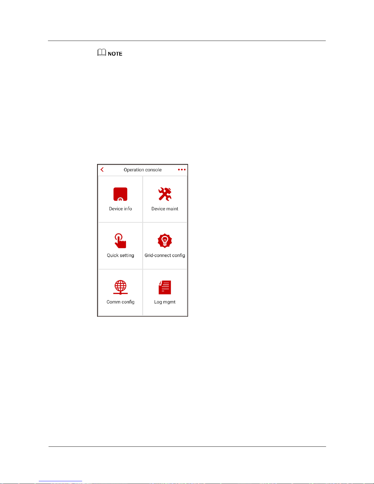
SUN2000L-(2KTL-5KTL)
User Manual
7 Operations on the Local FusionHome App
Issue 02 (2017-12-12)
Huawei Proprietary and Confidential
Copyright © Huawei Technologies Co., Ltd.
69
To change the configuration file to be imported, tap Change.
In the dialog box with Are you sure you want to configure the inverter connected router settings
again, if you tap Confirm, the router configurations saved before will be cleared. If you tap Cancel,
you only have to enter the saved router password.
After quick setting is complete, tap Switch to Router WiFi to switch to the Available WiFi
networks nearby screen and tap the corresponding router WiFi connection to switch to the router
WiFi network.
To connect to the router WiFi network from the mobile phone system after router parameters are
successfully set, you need to log out of the app and log in again.
After the management system is successfully connected, the SUN2000L will report the SN and
installer registration code. If the connection fails, another connection attempt will start after 10
seconds. The installer registration code is generated by the SUN2000L automatically and is used for
the installer to register with the management system and manage the inverter.
Figure 7-13 Operation console
----End
7.4.2 Querying the SUN2000L Information
To query the SUN2000L information, choose Device info from the Operation console
screen.
Querying Power Curves
You can query the current-day power curve and energy yield.
Page 77
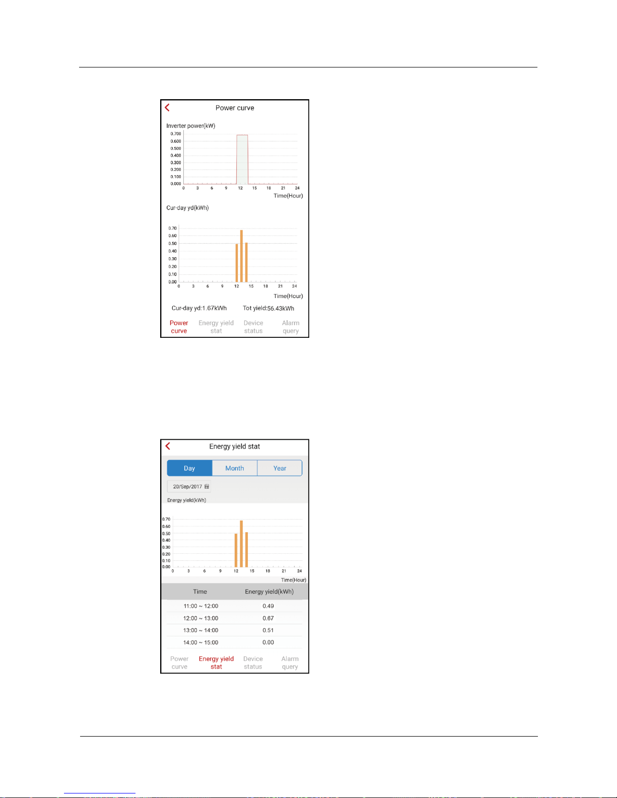
SUN2000L-(2KTL-5KTL)
User Manual
7 Operations on the Local FusionHome App
Issue 02 (2017-12-12)
Huawei Proprietary and Confidential
Copyright © Huawei Technologies Co., Ltd.
70
Figure 7-14 Power curve
Querying Energy Yields
You can query daily, monthly, and yearly energy yields.
Figure 7-15 Energy yield stat
Page 78
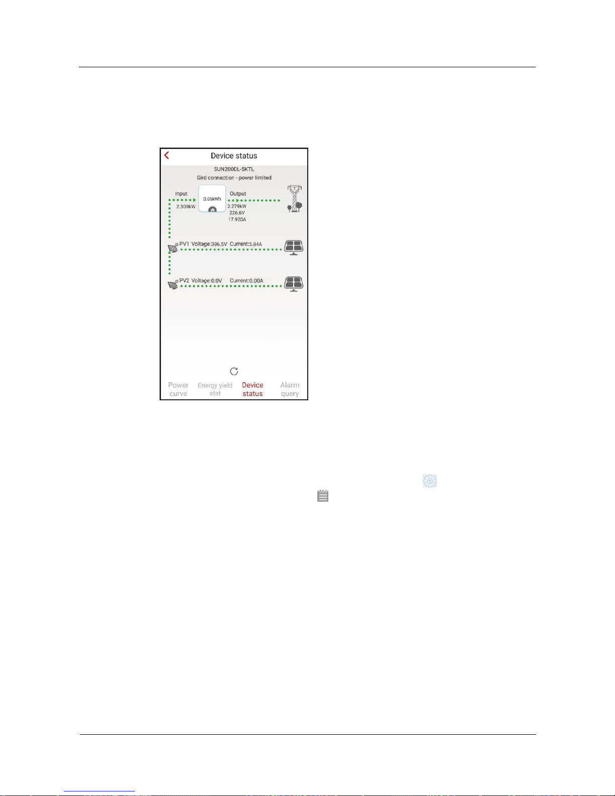
SUN2000L-(2KTL-5KTL)
User Manual
7 Operations on the Local FusionHome App
Issue 02 (2017-12-12)
Huawei Proprietary and Confidential
Copyright © Huawei Technologies Co., Ltd.
71
Querying Device Status
You can query the status of each device.
Figure 7-16 Device status
Querying Alarms
You can query active and historical alarms.
To set the sorting mode for active alarms or historical alarms, tap . To query the historical
alarms within a certain time range, tap and select the time range.
Page 79
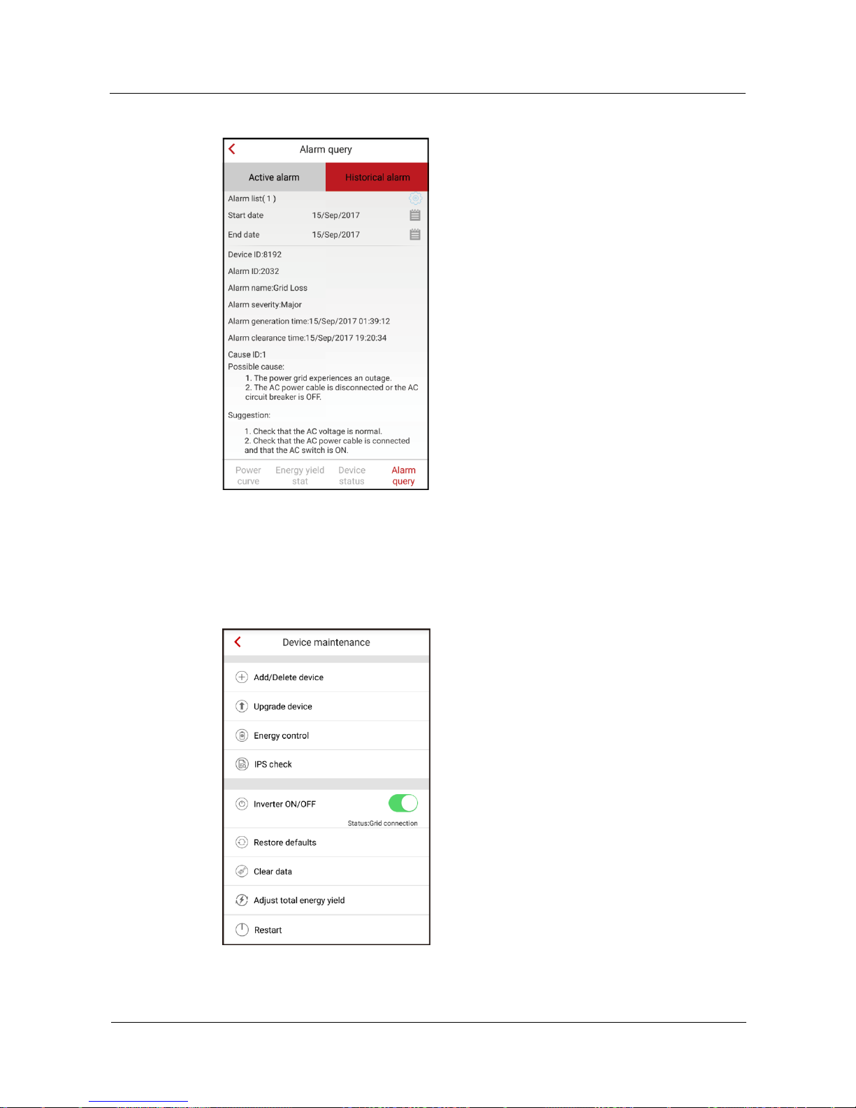
SUN2000L-(2KTL-5KTL)
User Manual
7 Operations on the Local FusionHome App
Issue 02 (2017-12-12)
Huawei Proprietary and Confidential
Copyright © Huawei Technologies Co., Ltd.
72
Figure 7-17 Alarm query
7.4.3 Maintaining the SUN2000L
To maintain the SUN2000L, choose Device maint from the Operation console screen.
Figure 7-18 Maintaining the SUN2000L
Page 80
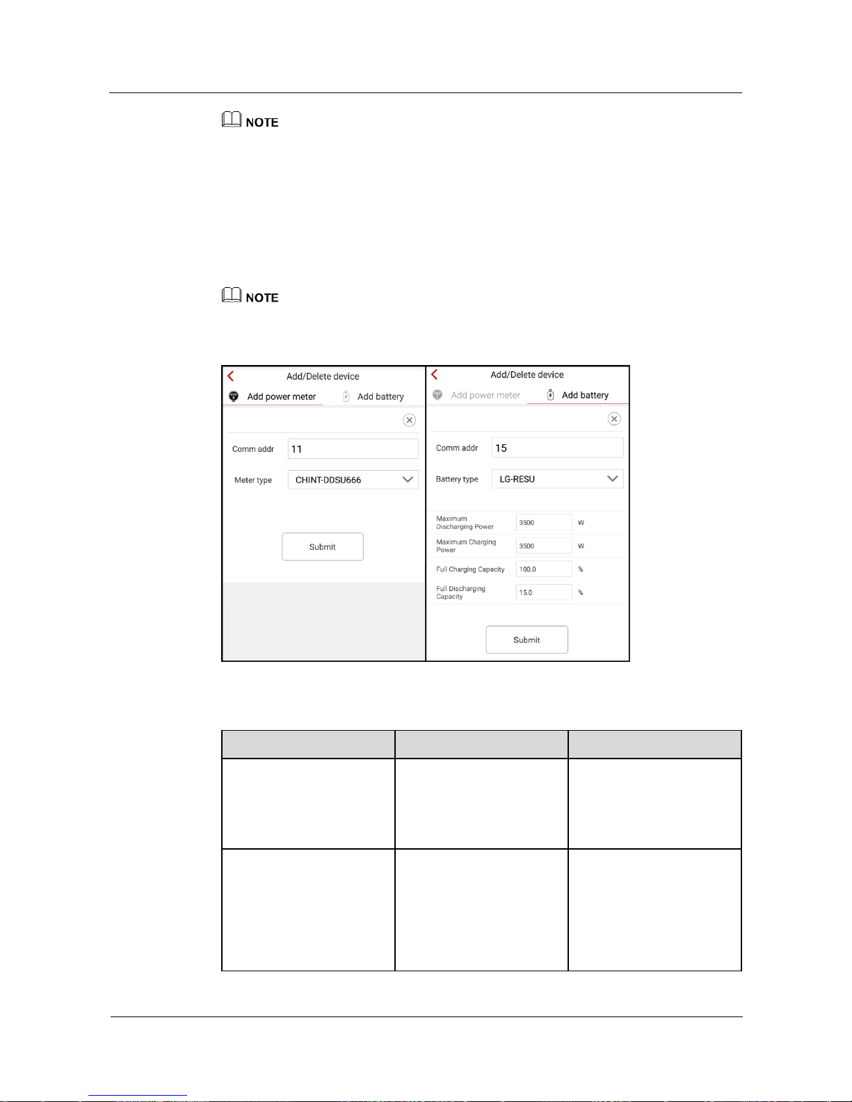
SUN2000L-(2KTL-5KTL)
User Manual
7 Operations on the Local FusionHome App
Issue 02 (2017-12-12)
Huawei Proprietary and Confidential
Copyright © Huawei Technologies Co., Ltd.
73
The IPS check function is available only for the Italy CEI0-21 grid code.
7.4.3.1 Adding/Deleting Devices
Procedure
Step 1 On the Operation console screen, choose Device maint > Add/Delete device, and add a
power meter and battery according to actual conditions. Tap Submit to deliver the device
information to the SUN2000L.
Each device must have a unique communications address.
Figure 7-19 Adding/Deleting devices
Table 7-1 Description of the parameters on the Add meter tab page
Parameter
Description
Value Range
Comm addr
Specifies the RS485 address
for the connected power
meter. The address should
be the same as the actual
address for the power meter.
[1, 247]
Meter model
Specifies the model of the
connected power meter. No
power meter of other models
can be connected.
CHINT-DDSU666
CCS-WNC-3Y-400-MB
Gavazzi-EM340DINAV
23XS1X
Gavazzi-EM111DINAV
81XS1X
Page 81
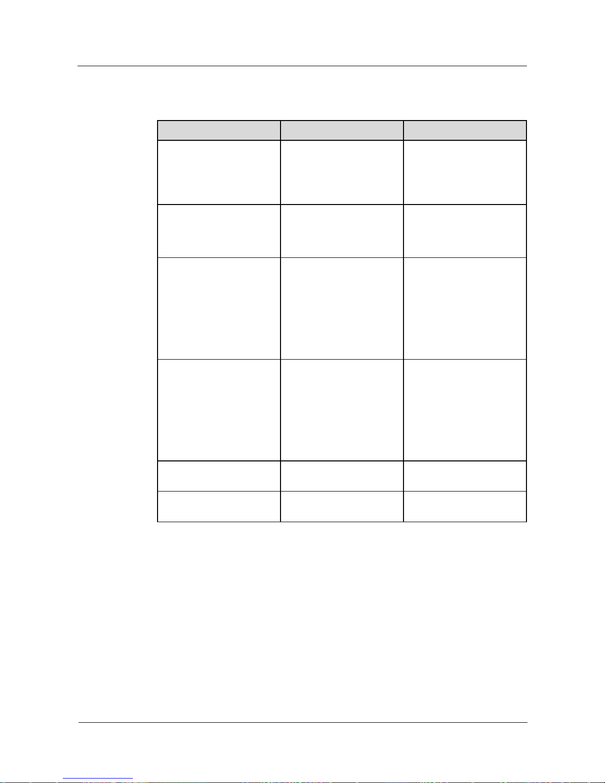
SUN2000L-(2KTL-5KTL)
User Manual
7 Operations on the Local FusionHome App
Issue 02 (2017-12-12)
Huawei Proprietary and Confidential
Copyright © Huawei Technologies Co., Ltd.
74
Table 7-2 Description of the parameters on the Add battery tab page
Parameter
Description
Value Range
Comm addr
Specifies the RS485 address
for the connected battery.
The address should be the
same as the actual address
for the battery.
[1, 247]
Battery type
Specifies the model of the
connected battery. No
battery of other models can
be connected.
LG-RESU
Maximum Discharging
Power
Specifies the maximum
battery charging power.
The maximum charging
power is limited by the
maximum output power of
the SUN2000L and whether
the charge/discharge
power function is enabled.
[0, 3500]
Maximum Charging Power
Specifies the maximum
battery discharging power.
The maximum discharging
power is limited by the
maximum output power of
the SUN2000L and whether
the charge/discharge
power function is enabled.
[0, 3500]
Full Charging Capacity
Specifies the battery
charging cutoff capacity.
[90, 100]
Full Discharging Capacity
Specifies the battery
discharging cutoff capacity.
[12, 20]
----End
7.4.3.2 Upgrading the Device
Prerequisites
You have obtained the upgrade file with the help of your supplier or Huawei engineers.
Context
In the iOS system, the upgrade file can be imported to the mobile phone over your
mailbox. The upgrade file name extension must be .zip. Manually select is unavailable.
Page 82
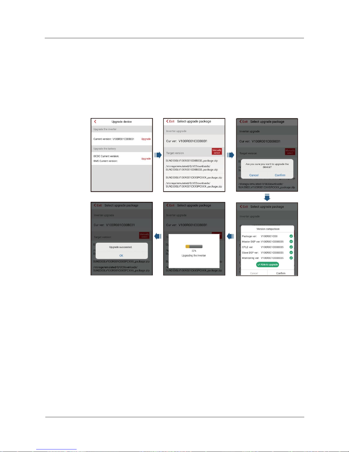
SUN2000L-(2KTL-5KTL)
User Manual
7 Operations on the Local FusionHome App
Issue 02 (2017-12-12)
Huawei Proprietary and Confidential
Copyright © Huawei Technologies Co., Ltd.
75
In the Android system, the upgrade file can be copied to the mobile phone. The upgrade
file name extension must be .zip and the file can be stored in your required directory.
Manually select is available.
Procedure
Step 1 On the Operation console screen, choose Device maint > Upg device and follow the
instructions.
Figure 7-20 Upgrading the SUN2000L
Page 83
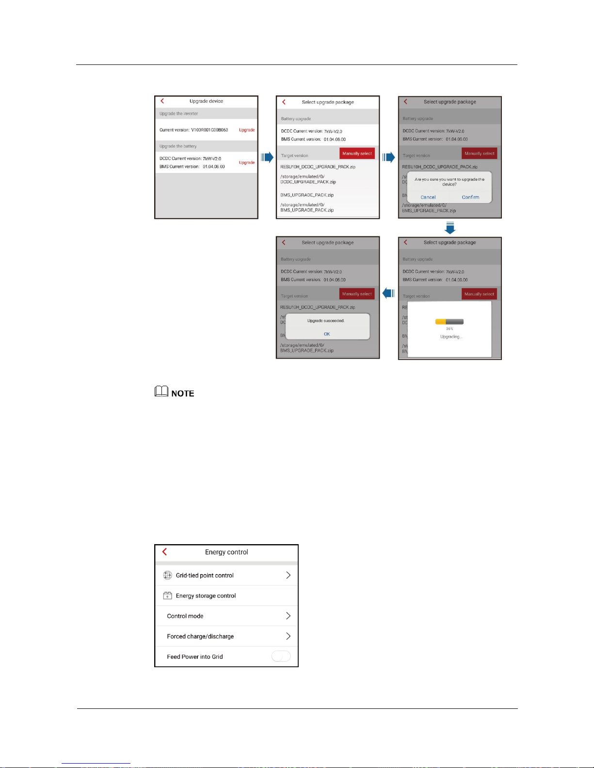
SUN2000L-(2KTL-5KTL)
User Manual
7 Operations on the Local FusionHome App
Issue 02 (2017-12-12)
Huawei Proprietary and Confidential
Copyright © Huawei Technologies Co., Ltd.
76
Figure 7-21 Upgrading the battery
There are DCDC and BMS upgrade packages for the battery. Choose one or both of the upgrade
packages based on the actual situation.
In the DCDC version, 7 kW corresponds to RESU10H and 5 kW corresponds to RESU7H.
----End
7.4.3.3 Energy Control
On the Operation console screen, choose Device maint > Energy control and perform the
corresponding operation.
Figure 7-22 Energy control
Page 84
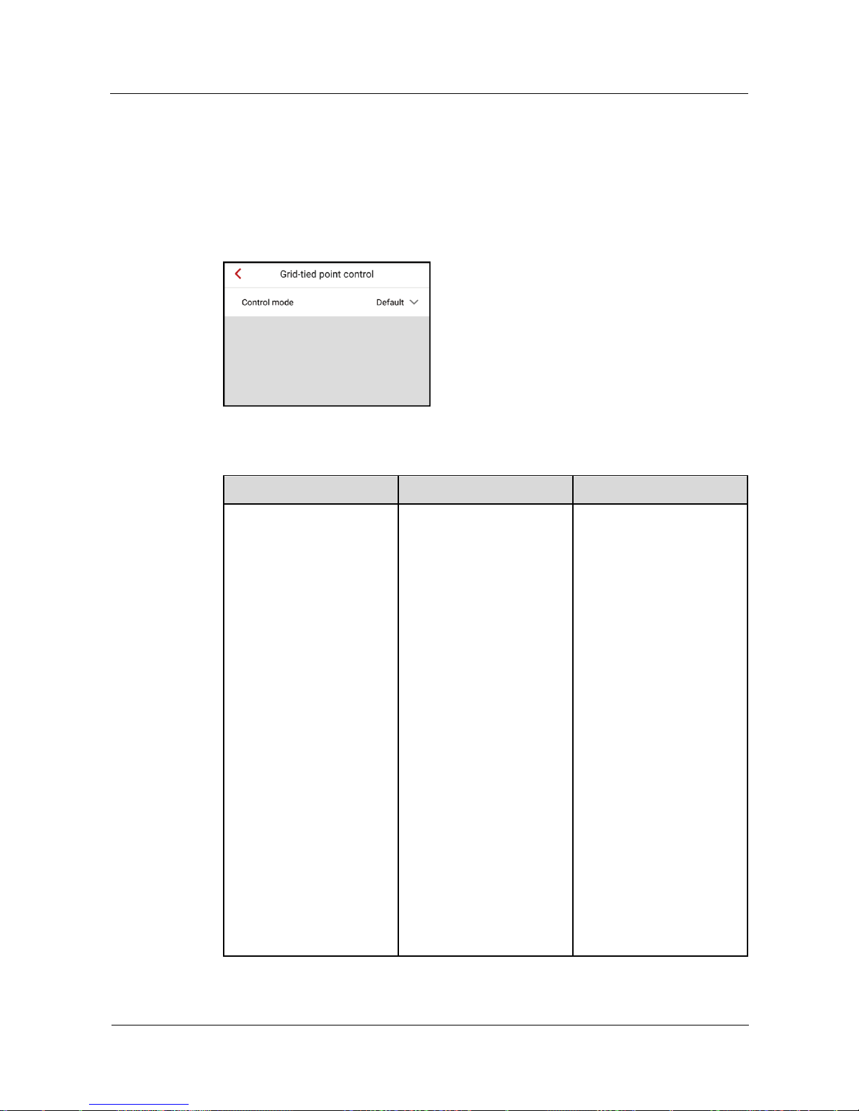
SUN2000L-(2KTL-5KTL)
User Manual
7 Operations on the Local FusionHome App
Issue 02 (2017-12-12)
Huawei Proprietary and Confidential
Copyright © Huawei Technologies Co., Ltd.
77
7.4.3.3.1 Grid-tied Point Control
Procedure
Step 1 On the Operation console screen, choose Device maint > Energy control > Grid-tied point
control and perform the corresponding operation.
Figure 7-23 Grid-tied point control
Table 7-3 Description of control mode parameters
Parameter
Description
Value Range
Control mode
If this parameter is set to
Default, the SUN2000L
output power is not limited.
The SUN2000L can export
its rated power to the power
grid.
If this parameter is set to
Grid connection with zero
power and the SUN2000L
is connected to a power
meter, the output power of
the SUN2000L is supplied
only to the local load, but
not the power grid.
If this parameter is set to
Power-limited Grid
Connection and the
SUN2000L is connected to a
power meter, the
SUN2000L supplies power
limited based on the setting
of Grid-tied Point Power
to the power grid. The time
for power-limited grid
connection precision is 3s.
The precision is [-3%Pmax,
0].
Default
Grid connection with
zero power
Power-limited Grid
Connection
Page 85
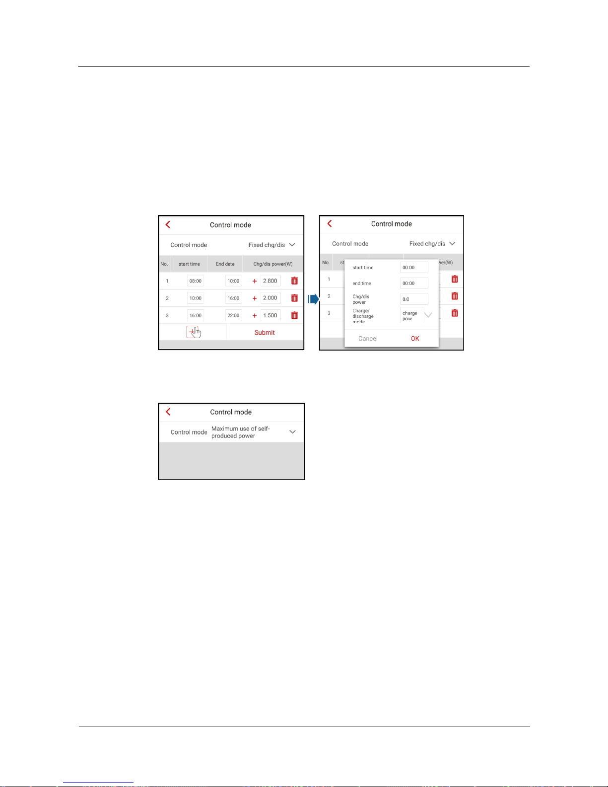
SUN2000L-(2KTL-5KTL)
User Manual
7 Operations on the Local FusionHome App
Issue 02 (2017-12-12)
Huawei Proprietary and Confidential
Copyright © Huawei Technologies Co., Ltd.
78
----End
7.4.3.3.2 Energy Storage Control
Control Mode
Step 1 On the Operation console screen, choose Device maintenance > Energy control > Energy
storage control > Control mode and perform the corresponding operation.
Figure 7-24 Fix chg/dis
Figure 7-25 Maximum use of self-produced power
Page 86
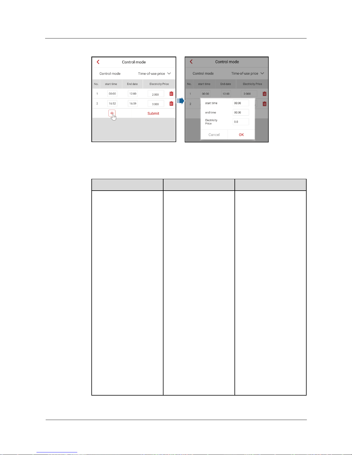
SUN2000L-(2KTL-5KTL)
User Manual
7 Operations on the Local FusionHome App
Issue 02 (2017-12-12)
Huawei Proprietary and Confidential
Copyright © Huawei Technologies Co., Ltd.
79
Figure 7-26 Time-of-use price
Table 7-4 Description of energy storage control parameters
Parameter
Description
Value Range
Control mode
If this parameter is set to
Fix chg/dis, charging or
discharging is allowed
during the configured
period. A maximum of
10 time periods can be
added.
If this parameter is set to
Maximum use of
self-produced power
and the SUN2000L is
connected to a power
meter, the output power
of the SUN2000L is
supplied to the local load
and the surplus power is
supplied to the power
grid.
If this parameter is set to
Time-of-use price, the
battery is discharged
when the electricity price
is high and charged
during other periods. 1/2
of higher prices among
added electricity prices
are high electricity
prices. A maximum of
10 time periods can be
added.
Fix chg/dis
Maximum use of
self-produced power
Time-of-use price
Page 87
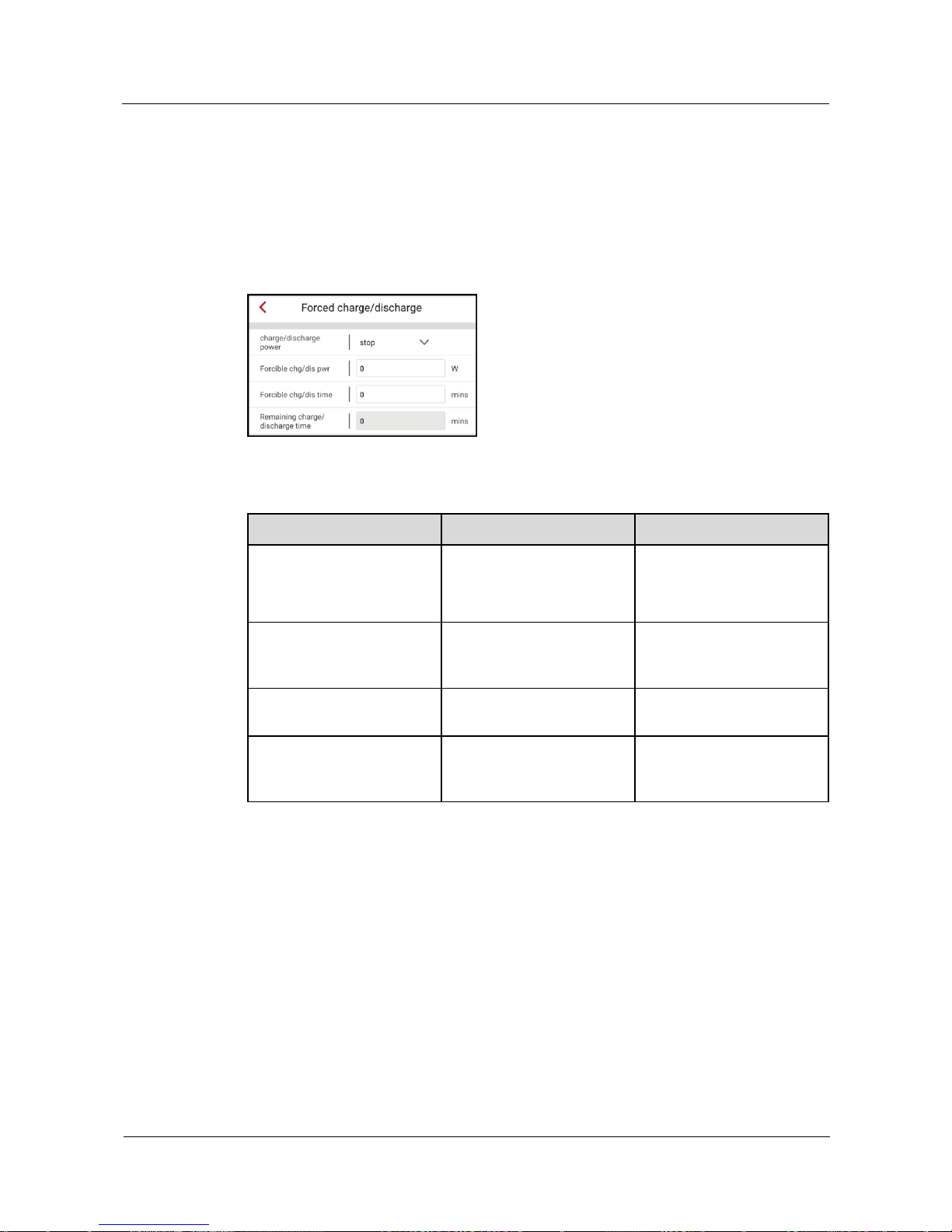
SUN2000L-(2KTL-5KTL)
User Manual
7 Operations on the Local FusionHome App
Issue 02 (2017-12-12)
Huawei Proprietary and Confidential
Copyright © Huawei Technologies Co., Ltd.
80
----End
Forced Charge/Discharge
Step 1 On the Operation console screen, choose Device maintenance > Energy control > Energy
storage control > Forced charge/discharge and perform the corresponding operation.
Figure 7-27 Forced charge/discharge
Table 7-5 Description of forced charge/discharge parameters
Parameter
Description
Value Range
Charge/discharge power
Specifies the forced
charge/discharge control
mode.
Stop
Charge power
Discharge power
Forcible chg/dis pwr (W)
Specifies the forced
charge/discharge power.
[Negative maximum
discharge power, maximum
charge power]
Forcible chg/dis time (mins)
Specifies the forced
charge/discharge duration.
[0, 1440]
Remaining charge/discharge
time (mins)
Displays the remaining
charge/discharge time. This
Parameter cannot be set.
[0, 1440]
----End
Feed Power into Grid
Step 1 On the Operation console screen, choose Device maintenance > Energy control > Energy
storage control > Feed Power into Grid and perform the corresponding operation.
Page 88
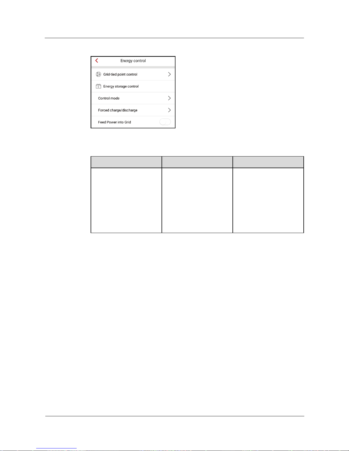
SUN2000L-(2KTL-5KTL)
User Manual
7 Operations on the Local FusionHome App
Issue 02 (2017-12-12)
Huawei Proprietary and Confidential
Copyright © Huawei Technologies Co., Ltd.
81
Figure 7-28 Feed Power into Grid
Table 7-6 Description Feed Power into Grid
Parameter
Description
Value Range
charge/discharge power
The power grid will charge
the battery if Feed Power
into Grid is enabled.
Feed Power into Grid is set
to Disable by default. If this
function is enabled, comply
with the grid charge
requirements stipulated in
local laws and regulations.
Disable
Enable
----End
7.4.3.4 IPS Check (Only for Italy CEI0-21 Grid Code)
Context
The Italy CEI0-21 grid code requires IPS check for the SUN2000L. During the self-check
process, the SUN2000L consecutively checks the protection thresholds and time for 10-min
overvoltage, level 1 overvoltage, level 1 undervoltage, level 1 overfrequency, and level 1
underfrequency. The SUN2000L shuts down after the check starts, and it restarts after the
check is successful.
Procedure
Step 1 On the Operation console screen, choose Device maintenance > IPS check to access the
IPS check screen.
Page 89
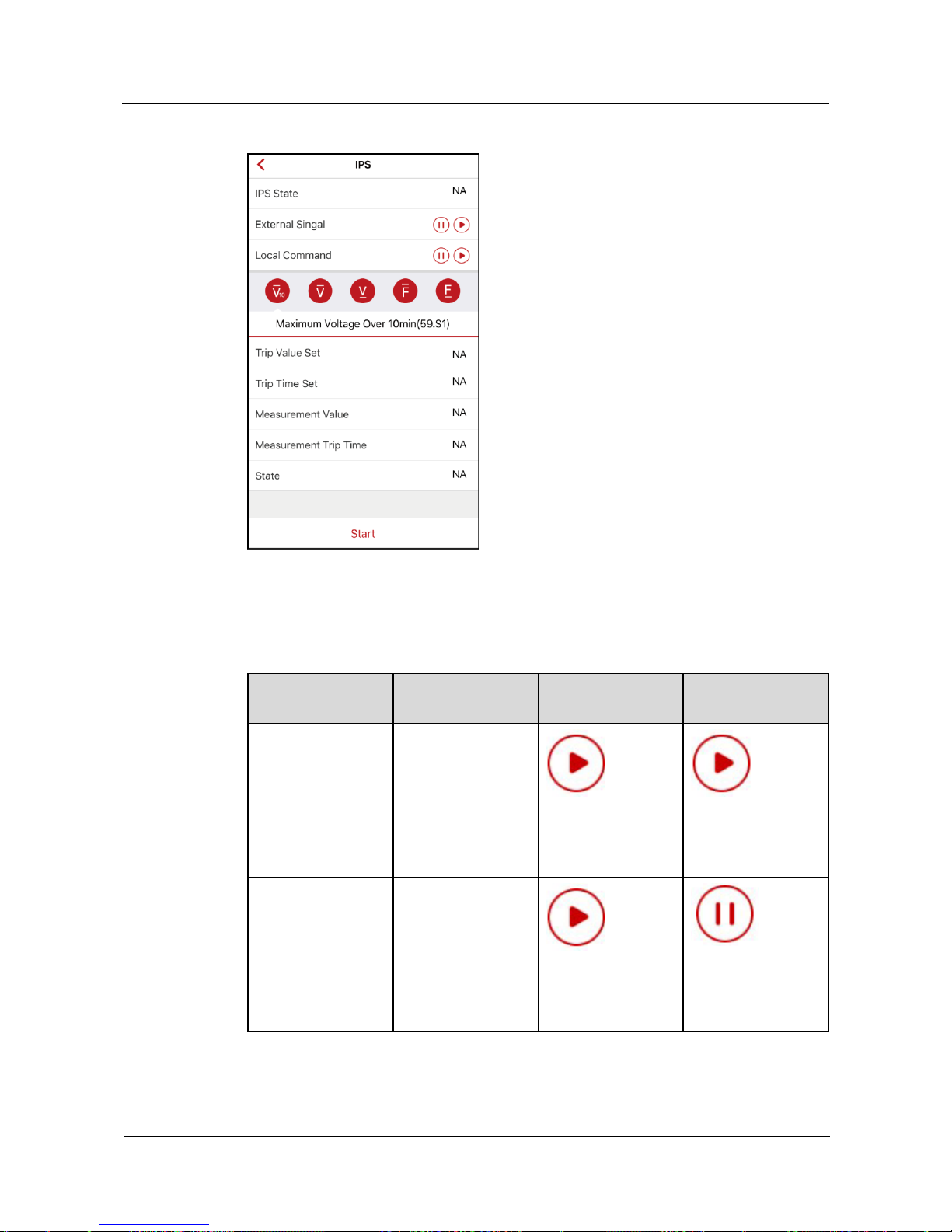
SUN2000L-(2KTL-5KTL)
User Manual
7 Operations on the Local FusionHome App
Issue 02 (2017-12-12)
Huawei Proprietary and Confidential
Copyright © Huawei Technologies Co., Ltd.
82
Figure 7-29 IPS check
Step 2 Choose to start the S1 or S2 check as required. The default check type is S1. To start the S2
check, you need to set External Signal or Local Command.
Table 7-7 Check type description
Check Type
Description
External Signal
Setting
Local Command
Setting
S1 (default)
The level 1
overfrequency
protection threshold
is 50.5 Hz and the
level 1
underfrequency
protection threshold
is 49.5 Hz.
S2
The level 1
overfrequency
protection threshold
is 51.5 Hz and the
level 1
underfrequency
protection threshold
is 47.5 Hz.
Page 90
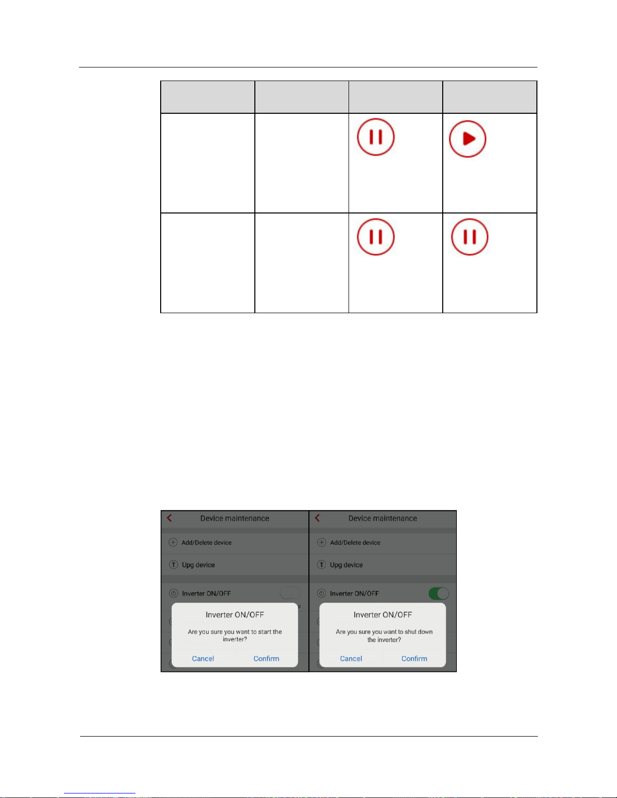
SUN2000L-(2KTL-5KTL)
User Manual
7 Operations on the Local FusionHome App
Issue 02 (2017-12-12)
Huawei Proprietary and Confidential
Copyright © Huawei Technologies Co., Ltd.
83
Check Type
Description
External Signal
Setting
Local Command
Setting
S2
The level 1
overfrequency
protection threshold
is 51.5 Hz and the
level 1
underfrequency
protection threshold
is 47.5 Hz.
S2
The level 1
overfrequency
protection threshold
is 51.5 Hz and the
level 1
underfrequency
protection threshold
is 47.5 Hz.
Step 3 Tap Start to start the check. After the check is complete, IPS State is displayed as Self-test
success.
----End
7.4.3.5 Starting or Shutting Down the SUN2000L
Procedure
Step 1 On the Operation console screen, choose Device maint > Inverter ON/OFF, and perform
operations as required.
Figure 7-30 Starting or shutting down the SUN2000L
Page 91
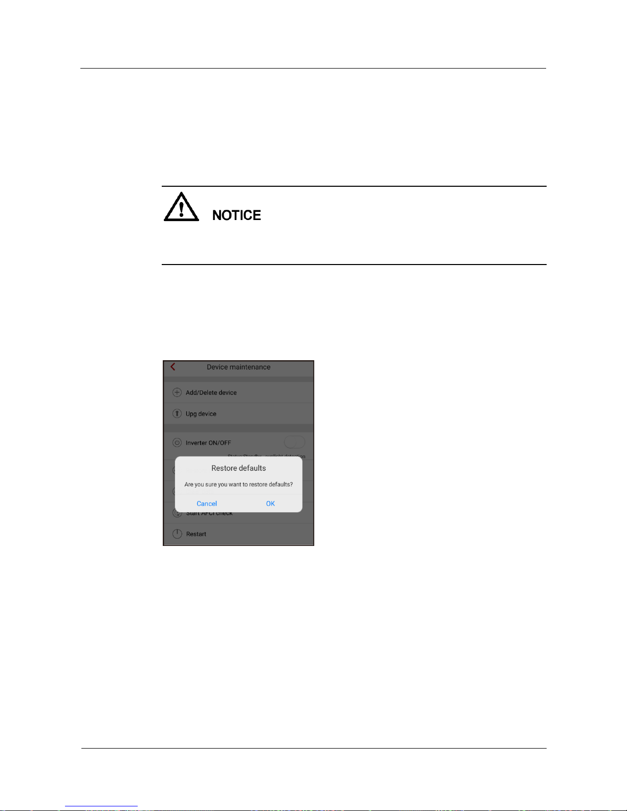
SUN2000L-(2KTL-5KTL)
User Manual
7 Operations on the Local FusionHome App
Issue 02 (2017-12-12)
Huawei Proprietary and Confidential
Copyright © Huawei Technologies Co., Ltd.
84
----End
7.4.3.6 Restoring Factory Defaults
Context
Perform this operation with caution because all configured parameters except the current date,
time, and networking related parameters will be restored to their factory defaults. This
operation will not affect operating information, alarm records, or system logs.
Procedure
Step 1 On the Operation console screen, choose Device maint > Restore defaults, and then tap
Confirm.
Figure 7-31 Restoring factory defaults
----End
7.4.3.7 Clearing Data
Context
Page 92
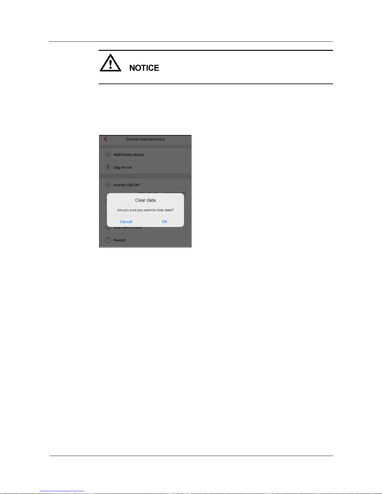
SUN2000L-(2KTL-5KTL)
User Manual
7 Operations on the Local FusionHome App
Issue 02 (2017-12-12)
Huawei Proprietary and Confidential
Copyright © Huawei Technologies Co., Ltd.
85
If you clear data, all alarms and energy yield data will be cleared.
Procedure
Step 1 On the Operation console screen, choose Device maint > Clear data.
Figure 7-32 Clearing data
----End
7.4.3.8 Adjusting Total Energy Yield
Procedure
Step 1 On the Operation console screen, choose Device maint > Adjust total energy yield and
perform the corresponding operation.
Page 93
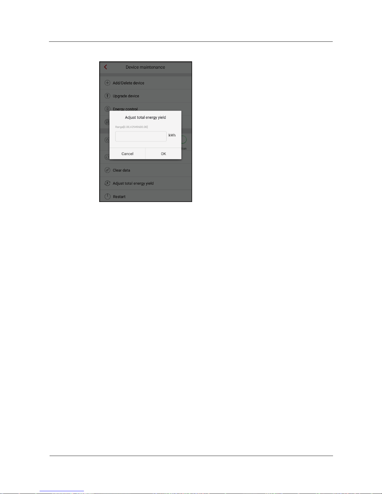
SUN2000L-(2KTL-5KTL)
User Manual
7 Operations on the Local FusionHome App
Issue 02 (2017-12-12)
Huawei Proprietary and Confidential
Copyright © Huawei Technologies Co., Ltd.
86
Figure 7-33 Adjusting total energy yield
Adjusting total energy yield: Specifies the initial value of inverter energy yield. This
parameter is used in SUN2000L replacement scenarios. Set the initial energy yield of the new
SUN2000L to the total energy yield of the old SUN2000L to ensure continuous statistics of
cumulative energy yield.
----End
7.4.3.9 Restarting the SUN2000L
Procedure
Step 1 To restart the app, choose Device maint > Restart from the Operation console screen.
Page 94
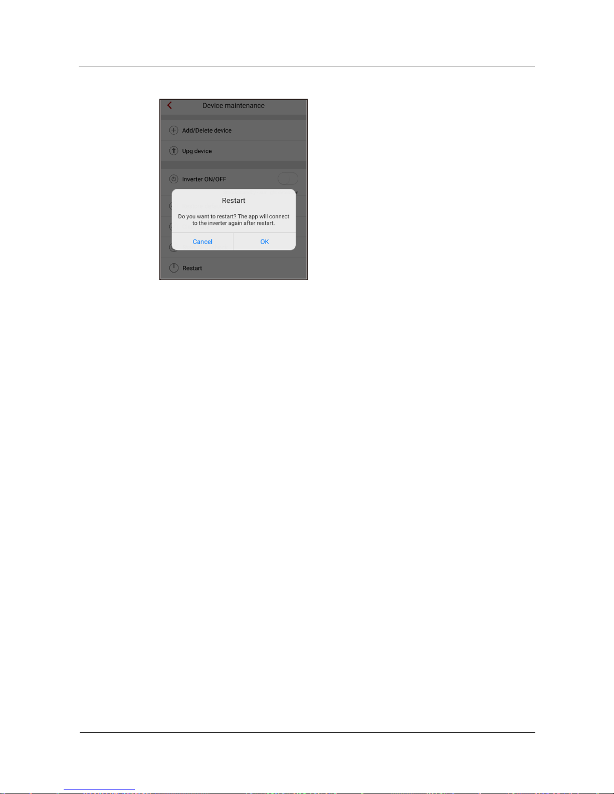
SUN2000L-(2KTL-5KTL)
User Manual
7 Operations on the Local FusionHome App
Issue 02 (2017-12-12)
Huawei Proprietary and Confidential
Copyright © Huawei Technologies Co., Ltd.
87
Figure 7-34 Restart
----End
7.4.4 Quick Setting
To enter the Quick setting screen, choose Quick setting from the Operation console screen.
The Quick setting screen provides two deployment modes. Select either of them based on site
requirements.
To exit the deployment, press the Back button on the mobile phone or tap Exit on the screen.
Method 1: quick setting
Step 1 Choose Quick setting from the Operation console screen and perform deployment by
following the instructions.
Page 95
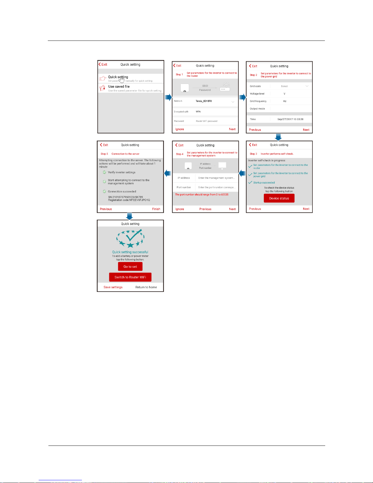
SUN2000L-(2KTL-5KTL)
User Manual
7 Operations on the Local FusionHome App
Issue 02 (2017-12-12)
Huawei Proprietary and Confidential
Copyright © Huawei Technologies Co., Ltd.
88
Figure 7-35 Quick setting
Page 96

SUN2000L-(2KTL-5KTL)
User Manual
7 Operations on the Local FusionHome App
Issue 02 (2017-12-12)
Huawei Proprietary and Confidential
Copyright © Huawei Technologies Co., Ltd.
89
Set the grid code that applies to the country or region where the PV plant is located and the
SUN2000L model.
If there is no need to connect to the router or management system, skip relevant steps.
After the management system is successfully connected, the SUN2000L will report the SN
and installer registration code. If the connection fails, another connection attempt will start
after 10 seconds. The installer registration code is generated by the SUN2000L
automatically and is used for the installer to register with the management system and
manage the inverter.
For the operations about how to add devices, see 7.4.3.1 Adding/Deleting Devices.
After quick setting is complete, tap Switch to Router WiFi to switch to the Available
WiFi networks nearby screen and tap the corresponding router WiFi connection to switch
to the router WiFi network.
To connect to the router WiFi network from the mobile phone system after router
parameters are successfully set, you need to log out of the app and log in again.
After following all the instructions on the Quick setting screen, tap Save settings to store
the configurations or tap Return to home to return to the Operation console screen.
----End
Method 2: use the saved file
Before choosing Use saved file for quick setting, ensure that the corresponding configuration
file is saved in your mobile phone. To generate a configuration file, tap Save settings on the
Quick setting screen.
Step 1 Choose Quick setting > Use saved file from the Operation console screen and perform
deployment by following the instructions.
Page 97
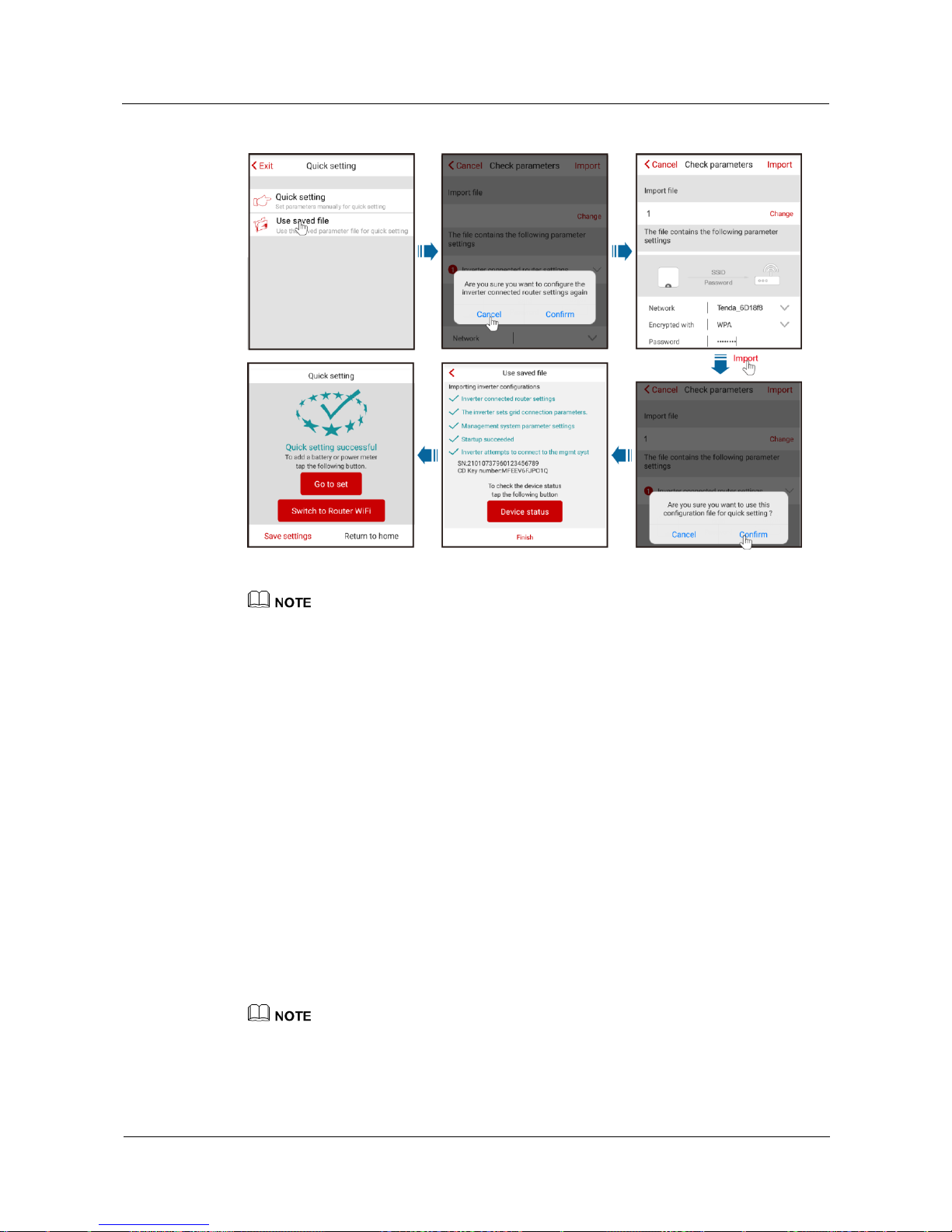
SUN2000L-(2KTL-5KTL)
User Manual
7 Operations on the Local FusionHome App
Issue 02 (2017-12-12)
Huawei Proprietary and Confidential
Copyright © Huawei Technologies Co., Ltd.
90
Figure 7-36 Performing quick setting using a saved file
To change the configuration file to be imported, tap Change.
In the dialog box with Are you sure you want to configure the inverter connected router settings
again, if you tap Confirm, the router configurations saved before will be cleared. If you tap Cancel,
you only have to enter the saved router password.
After quick setting is complete, tap Switch to Router WiFi to switch to the Available WiFi
networks nearby screen and tap the corresponding router WiFi connection to switch to the router
WiFi network.
To connect to the router WiFi network from the mobile phone system after router parameters are
successfully set, you need to log out of the app and log in again.
After the management system is successfully connected, the SUN2000L will report the SN and
installer registration code. If the connection fails, another connection attempt will start after 10
seconds. The installer registration code is generated by the SUN2000L automatically and is used for
the installer to register with the management system and manage the inverter.
----End
7.4.5 Setting Grid-Connection Parameters
Setting Grid-Connection Parameters
To set grid codes, choose Grid-connect config from the Operation console screen.
Voltage level, Grid frequency, and Output mode do not have to be set because they are associated
with the grid code.
Page 98
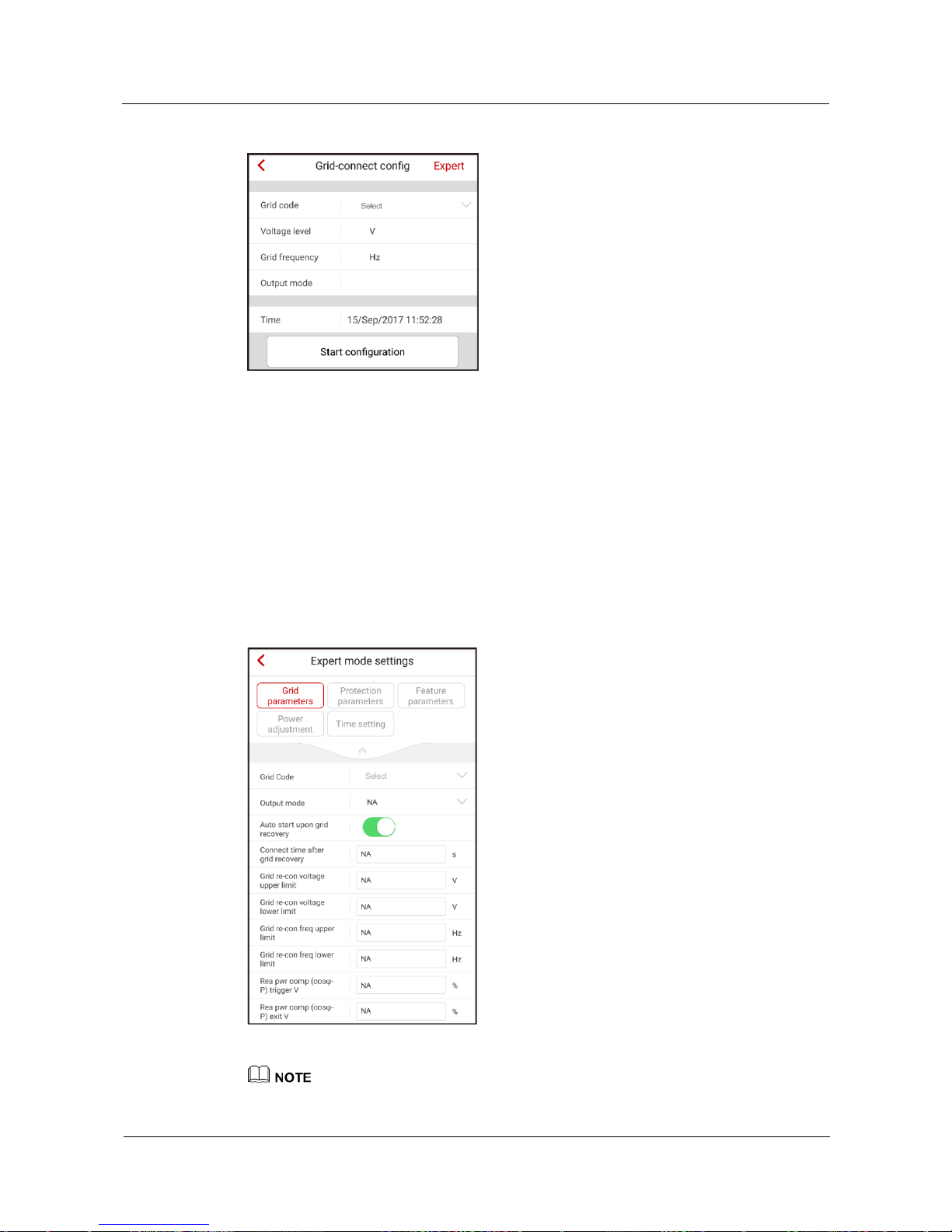
SUN2000L-(2KTL-5KTL)
User Manual
7 Operations on the Local FusionHome App
Issue 02 (2017-12-12)
Huawei Proprietary and Confidential
Copyright © Huawei Technologies Co., Ltd.
91
Figure 7-37 Grid-connect config
Expert Mode
To set grid parameters, protection parameters, feature parameters, power adjustment
parameters, and time in expert mode, choose Grid-connect config > Expert from the
Operation console screen.
7.4.5.1 Setting Grid Parameters
To set grid parameters, choose Grid-connect config > Expert > Grid parameters from the
Operation console screen.
Figure 7-38 Grid parameters
Vn represents the rated voltage and Fn represents the rated frequency.
Page 99
SUN2000L-(2KTL-5KTL)
User Manual
7 Operations on the Local FusionHome App
Issue 02 (2017-12-12)
Huawei Proprietary and Confidential
Copyright © Huawei Technologies Co., Ltd.
92
The grid parameter values vary with grid codes. The displayed values prevail.
Table 7-8 Description of grid parameters
Parameter
Description
Value Range
Grid code
Set this parameter based on
the grid code of the country
or region where the
SUN2000L is used and the
SUN2000L application
scenario.
For details of the grid codes,
see A Grid Codes.
The default value varies
depending on the model.
The displayed value
prevails.
Output mode
Single-phase
Split-phase
Dual–live wire
Auto start upongrid
recovery
Specifies whether the
SUN2000L can start
automatically when the
power grid recovers.
Disable
Enable
Connect time after grid
recovery (s)
Specifies the time after
which the SUN2000L
begins restarting after the
power grid recovers.
[0, 900]
Grid re-con voltage upper
limit (V)
For a specific grid code, if
the grid voltage exceeds the
upper threshold, the
SUN2000L is not allowed to
connect to the power grid.
[100%Vn, 136%Vn]
Grid re-con voltage lower
limit (V)
For a specific grid code, if
the grid voltage is below the
lower threshold, the
SUN2000L is not allowed to
connect to the power grid.
[45%Vn, 95%Vn]
Grid re-con freq upper limit
(Hz)
For a specific grid code, if
the grid frequency exceeds
the upper threshold, the
SUN2000L is not allowed to
connect to the power grid.
[100%Fn, 112%Fn]
Grid re-con freq lower limit
(Hz)
For a specific grid code, if
the grid frequency is below
the lower threshold, the
SUN2000L is not allowed to
connect to the power grid.
[85%Fn, 100%Fn]
Rea pwr comp (cosφ-P)
trigger V (%)
Specifies the voltage
threshold for triggering
reactive power
compensation when low
voltage ride-through
(LVRT) occurs.
[100, 110]
Rea pwr comp (cosφ-P) exit
Specifies the voltage
[90, 100]
Page 100
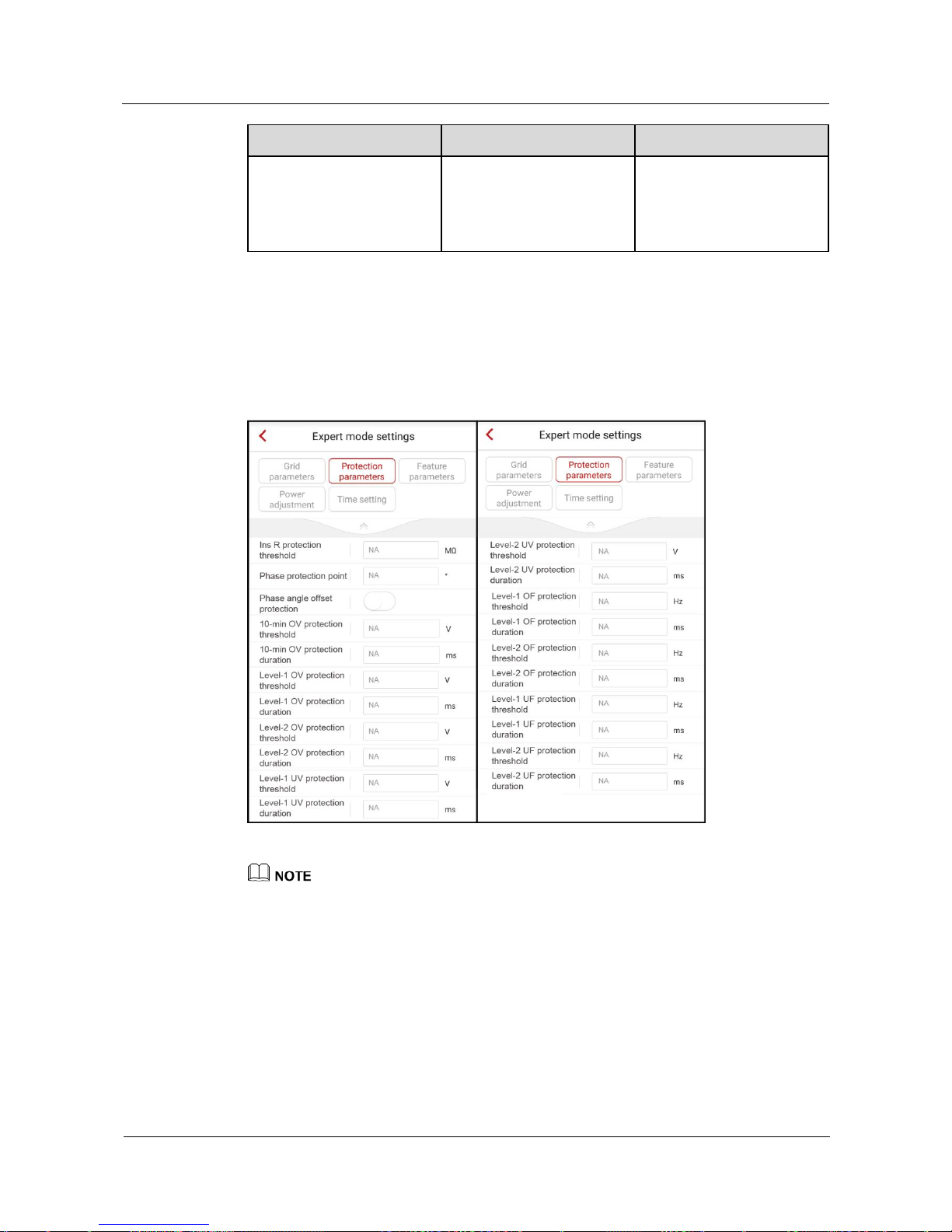
SUN2000L-(2KTL-5KTL)
User Manual
7 Operations on the Local FusionHome App
Issue 02 (2017-12-12)
Huawei Proprietary and Confidential
Copyright © Huawei Technologies Co., Ltd.
93
Parameter
Description
Value Range
V (%)
threshold for exiting
reactive power
compensation when the
SUN2000L recovers from
LVRT.
7.4.5.2 Setting Protection Parameters
To set protection parameters, choose Grid-connect config > Expert > Protection
parameters from the Operation console screen.
Figure 7-39 Protection parameters
Vn represents the rated voltage and Fn represents the rated frequency.
The protection parameter values vary with the grid code. The displayed values prevail.
 Loading...