

Page 1
HUAWEI TECHNOLOGIES CO., LTD.
SUN2000-(90KTL, 95KTL, 100KTL, 105KTL) Series
Quick Guide
Issue: 03
Part Number: 31509904
Date: 2018-07-16
Page 2
Copyright © Huawei Technologies Co., Ltd.
2018. All rights reserved.
1
Overview
1
• The information in this document is subject to change without notice. Every effort has been
made in the preparation of this document to ensure accuracy of the contents, but all statements,
information, and recommendations in this document do not constitute a warranty of any kind,
express or implied.
• Only qualified and trained electrical technicians are allowed to operate the device. Operators
should understand the composition and working principles of the grid-tied PV power system and
local standards.
• Before installing the device, read the user manual carefully to get familiar with product
information and safety precautions. Huawei shall not be liable for any consequences caused by
the violation of the storage, transportation, installation, and operation regulations specified in this
document and the user manual.
• Use insulated tools when installing the device. For personal safety, wear proper personal
protective equipment (PPE).
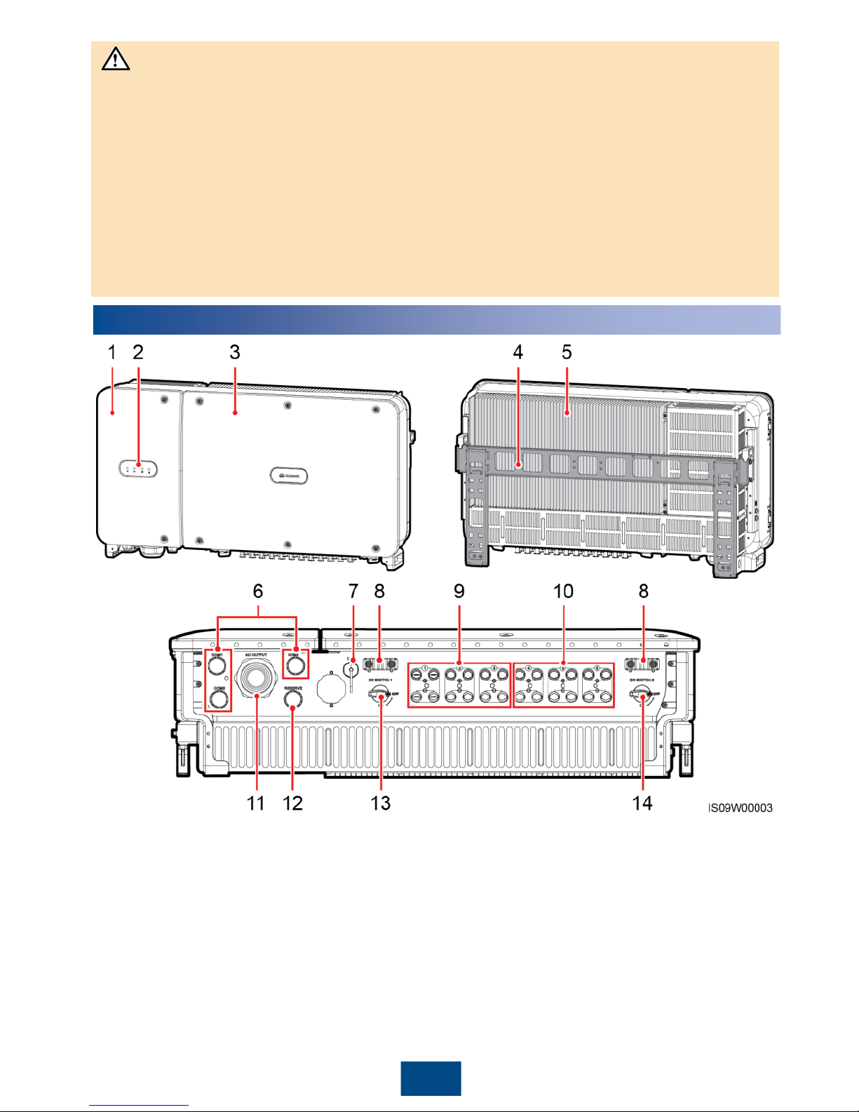
(1) Maintenance compartment door
(2) LED indicators
(3) Host panel
(4) Mounting bracket
(5) Heat sink
(6) Communications cable glands
(
COM1/COM2/COM3)
(7) USB port (USB)
(8) Auxiliary handles
(9) DC input terminals (+/
–; controlled by DC
SWITCH 1)
(10) DC input terminals (+/
–; controlled by DC
SWITCH 2)
(11) AC output cable gland (AC OUTPUT)
(12) Reserved cable gland (RESERVE)
(13) DC switch 1 (DC SWITCH 1)
(14) DC switch 2 (DC SWITCH 2)
NOTICE
Page 3
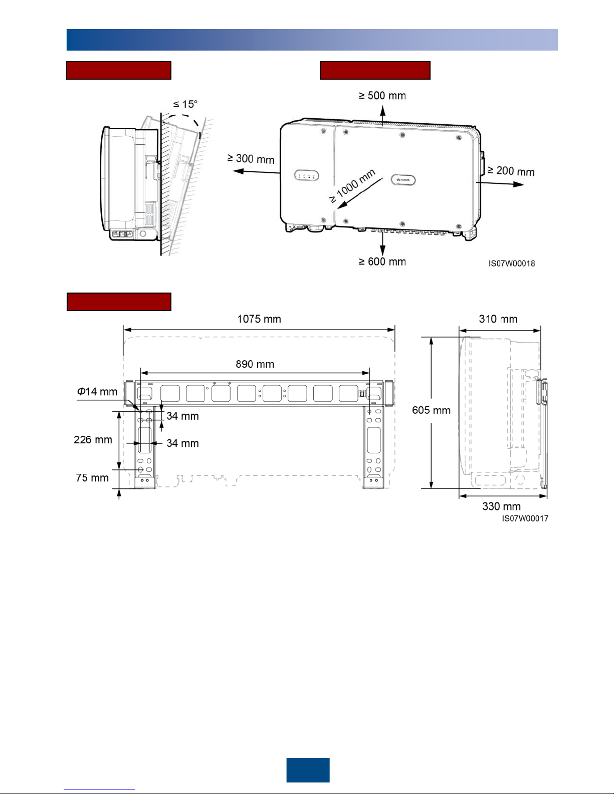
Recommended: 600 mm ≤ bottom space ≤ 730 mm
2
Installation Requirements
2
Dimensions
Angle Space
Page 4
3
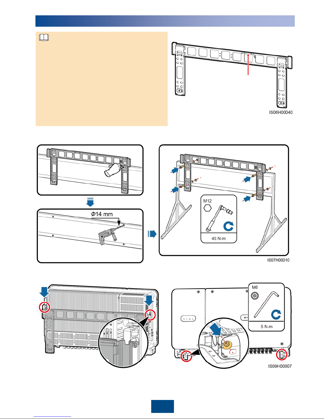
1. Install the mounting bracket.
2. Install the SUN2000 on the mounting bracket. 3. Tighten security Torx screws.
You are advised to apply anti-rust paint
on the hole positions for protection.
3
Installing the SUN2000
• The M12x40 bolt assemblies are delivered with
the SUN2000. If the bolt assembly length does
not meet the installation requirements, prepare
M12 bolt assemblies by yourself and use them
together with the delivered M12 nuts.
• Before installing the mounting bracket, remove
the security Torx wrench from the mounting
bracket and save it for later use.
• This document introduces how to install the
SUN2000 on a support as an example. For
details about wall-mounted installation, see the
user manual.
Position for bundling a
security Torx wrench
NOTE
Page 5
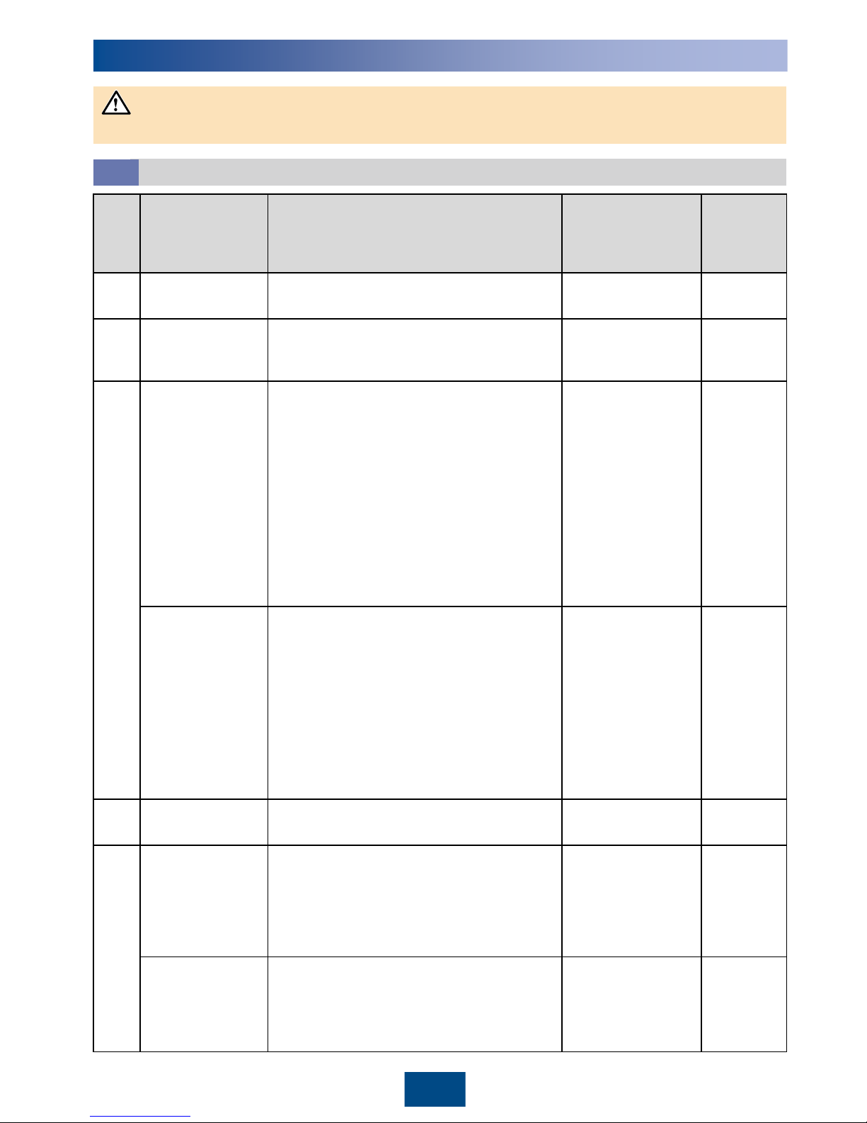
No.
Cable
Type
Recommended
Conductor
Cross
-Sectional
Area
Outer
Diameter
1
PE cable
Outdoor copper cable and M8 OT/DT
terminals
≥
16 mm
2
N/A
2
(Optional)
Tracking system
power cable
Three
-core outdoor copper cable with
dual
-layer protection
6 mm
2
14–18 mm
3
AC output power
cable (OT/DT
terminal)
•
If you connect a PE cable to the PE
point on the enclosure, you are
advised to use a three-core (L1, L2,
and L3) outdoor copper cable and
M10 OT/DT terminals (L1, L2, and L3).
•
If you connect a PE cable to the PE
point in the maintenance compartment,
you do not need to prepare a PE
cable separately but are advised to
use a four-core (L1, L2, L3, and PE)
outdoor copper cable, M10 OT/DT
terminals (L1, L2, and L3), and M8
OT/DT terminals (PE).
•
L1, L2, L3: 35
mm
2
•
PE: ≥ 16 mm
2
24–57 mm
AC output power
cable (terminal
clamp)
•
If you connect a PE cable to the PE
point on the enclosure, you are
advised to use a three-core (L1, L2,
and L3) outdoor copper cable.
•
If you connect a PE cable to the PE
point in the maintenance compartment,
you do not need to prepare a PE
cable separately but are advised to
use a four-core (L1, L2, L3, and PE)
outdoor copper cable and M8 OT/DT
terminals (PE).
•
L1, L2, L3: 35
mm
2
•
PE: ≥ 16 mm
2
24–57 mm
4
DC input power
cable
PV cable that meets the 1500 V standard
4
mm
2
4.5
–7.8
mm
5
RS485
communications
cable
(connected to a
terminal block;
recommended)
Multi
-paired, individually foil shielded
cable that complies with local standards
and M6 OT terminals
1
mm
2
14–18 mm
RS485
communications
cable
(connected to a
network port)
CAT 5E outdoor shielded network cable
with internal resistance ≤ 1.5 ohms/10 m,
as well as the shielded RJ45 connector
N/A
7
–9 mm
4
Preparing Cables
4.1
4
Electrical Connections
Connect cables in accordance with the local installation laws and regulations.
NOTICE
Page 6
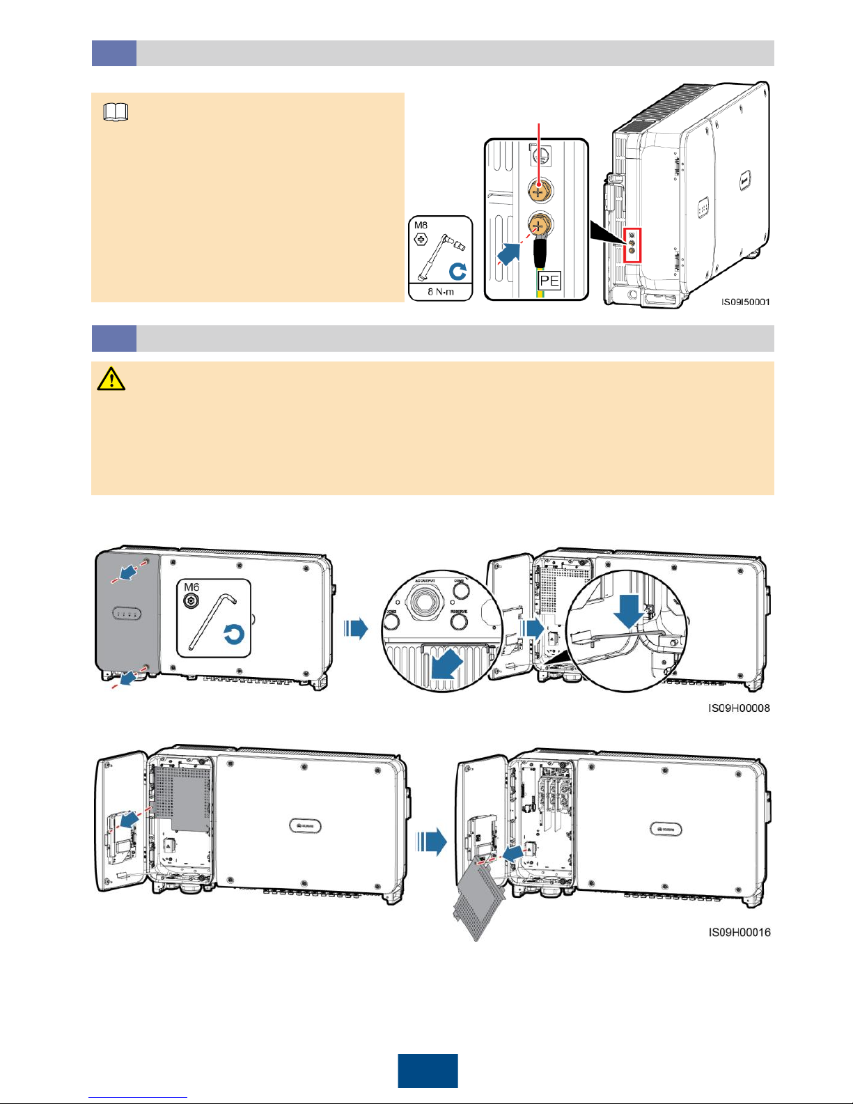
Reserved PE point
5
Installing the PE Cable (on the Enclosure)
4.2
• It is recommended that the PE cable
be connected to a nearby PE point.
Connect the PE points of all
SUN2000s in the same PV array to
ensure equipotential connections to PE
cables.
• To enhance the corrosion resistance of
a ground terminal, you are advised to
apply silica gel or paint on it after
connecting the PE cable.
1. Loosen the screws on the maintenance
compartment door.
Opening the Maintenance Compartment Door
4.3
• Do not open the host panel of the SUN2000.
• Before opening the SUN2000 maintenance compartment door, turn off the downstream AC
output switch and two DC switches at the bottom.
• Do not open the maintenance compartment door in rainy or snowy days. If you must, take
protective measures to prevent rain or snow from entering the maintenance compartment.
• Do not leave unused screws in the maintenance compartment.
2. Open the maintenance compartment door
and adjust the support bar.
3. Remove the cover and hang it on the hook of the enclosure door.
WARNING
NOTE
Page 7
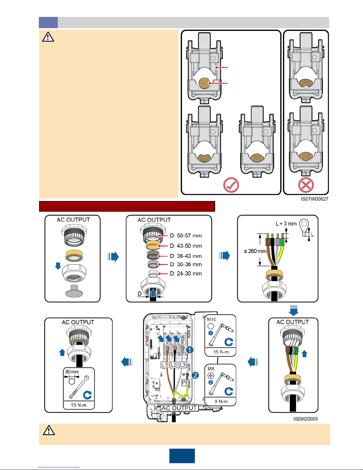
6
Installing the AC Output Power Cable
4.4
• This document introduces how to install
the four-core AC output power cable,
which can be a reference for installing the
three-core cable. The three-core cable
does not need a PE cable installed in the
maintenance compartment.
• To avoid damaging the rubber liner, do
not route a cable with a crimped OT/DT
terminal directly through it.
• Do not adjust the cable when the sealing
nut is tightened. Otherwise, the rubber
liner will shift, which affects the IP rating of
the device.
• Ensure that AC terminations are secured.
Failing to do so may cause the SUN2000
to malfunction or damage to its terminal
block by issues such as overheating.
• Sufficient slack should be provided in the
PE cable to ensure that the last cable
bearing the force is the PE cable when
the AC output power cable bears pulling
force due to force majeure.
Terminal clamp
AC output
power cable
Ensure that the AC
output power cable
and terminal clamp
are in good contact.
Installation Procedure (Using the OT/DT Terminal)
After the AC output power cable is installed, seal the cable gland.
NOTICE
NOTICE
Page 8
Number of
PV Strings
Terminal Selection
Number of
PV Strings
Terminal Selection
6
Connects to routes 2, 4, 6, 8, 10,
and 12.
7
Connects to routes 2, 4, 6, 8, 9, 10,
and 12.
8
Connects to routes 1, 2, 4, 6, 8, 9,
10, and 12.
9
Connects to routes 1, 2, 4, 6, 7, 8, 9,
10, and 12.
10
Connects to routes 1, 2, 4, 6, 7, 8, 9,
10, 11, and 12.
11
Connects to routes 1, 2, 3, 4, 6, 7, 8, 9,
10, 11, and 12.
7
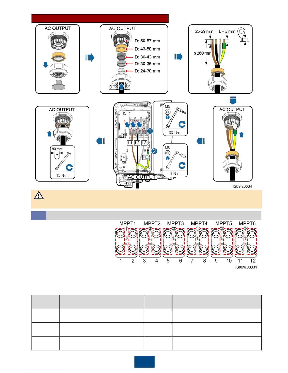
Installation Procedure (Using the Terminal Clamp)
Installing the DC Input Power Cable
4.5
When DC inputs are not fully configured, the input terminals should meet the following requirements:
1. Evenly distribute DC input power cables on the DC input terminals controlled by the two DC switches.
2. Maximize the number of connected MPPT circuits.
For example, if the number of input routes is 6–11, the recommended DC input terminals are as follows:
After the AC output power cable is installed, seal the cable gland.
NOTICE
The SUN2000 provides 12 DC
input terminals, which are
controlled by its two DC switches.
DC SWITCH 1 controls DC input
terminals 1–6 (MPPT1–3) and DC
SWITCH 2 controls DC input
terminals 7–12 (MPPT4–6).
Page 9
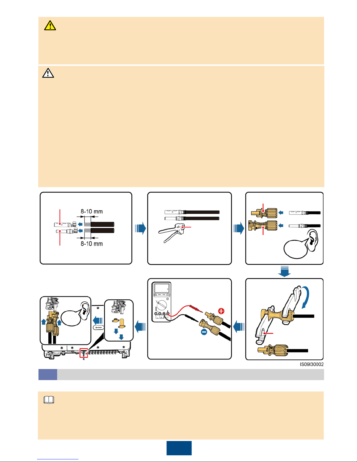
8
1. Use the positive and negative Amphenol UTX metal contacts and DC connectors supplied with
the SUN2000. Using other positive and negative metal contacts and DC connectors may result in
serious consequences. The caused device damage is not covered under any warranty.
2. Before connecting the DC input power cable, label the cable polarities to ensure correct cable
connections. Otherwise, the SUN2000 may be damaged.
3. Measure the voltage at the DC input end using a multimeter. If the voltage is a negative value,
the DC input polarity is incorrect. Correct the polarity. If the voltage is greater than 1500 V, too
many PV modules are configured to the same string. Remove some PV modules.
4. If the DC input power cable is reversely connected and the DC switch is turned on, do not
perform operations on the DC switch or the positive/negative connectors immediately. Otherwise,
the device may be damaged. The caused device damage is not covered under any warranty.
Wait until the night when solar irradiance declines and the PV string current drops to below 0.5 A.
Then turn the two DC switches to the OFF position, remove the positive and negative DC input
power connectors, and correct the polarity of the DC input power cable.
Positive connector
Negative
connector
Positive metal contact
Negative metal contact
Ensure that the cable
cannot be pulled out after
being crimped.
UTXTC0002
(Amphenol)
Click
Ensure that the
locking nut is
secured.
UTXTWA001
(Amphenol)
Click
DC voltage
measurement range
≥ 1500 V DC
Selecting the Communications Mode
4.6
• If PLC is selected, no RS485 communications cable is required to connect to the SUN2000, but
the AC power cable needs to connect to the SmartLogger2000 that supports PLC.
• If RS485 is selected, connect an RS485 communications cable to the SUN2000, but the AC
power cable does not need to connect to a SmartLogger2000 that supports PLC.
The SUN2000 supports PLC and RS485 communications modes, but you can only choose one of them.
NOTICE
NOTE
• Ensure that the PV module output is well insulated to ground.
• Before inserting the positive and negative connectors respectively into the positive and negative
DC input terminals of the SUN2000, ensure that the DC voltage does not exceed 1500 V DC using
a multimeter and that the cable polarities are correct. Otherwise, the SUN2000 will be damaged.
WARNING
Page 10
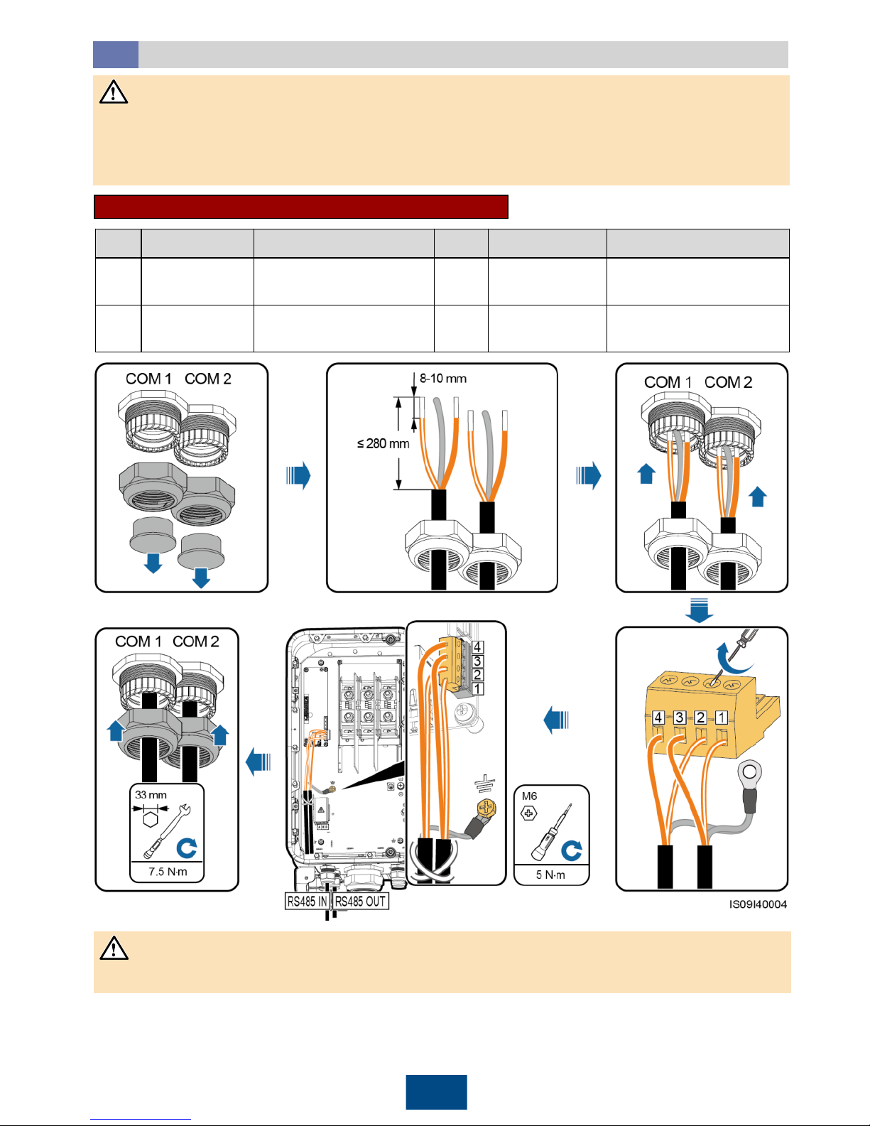
9
Installing the RS485 Communications Cable
4.7
1. When routing the communications cable, separate it from power cables and connect the shield
layer to the ground point to prevent communication from being affected.
2. The RS485 communications cable can connect to a terminal block or an RJ45 network port.
Select one in actual installation.
Connecting to a Terminal Block (Recommended)
No.
Definition
Description
No.
Definition
Description
1
RS485A IN
RS485A, RS485
differential signal+
2
RS485A OUT
RS485A, RS485
differential signal+
3
RS485B IN
RS485B, RS485
differential signal
–
4
RS485B OUT
RS485B, RS485
differential signal
–
After the RS485 communications cable is installed, seal the cable gland.
NOTICE
NOTICE
Page 11
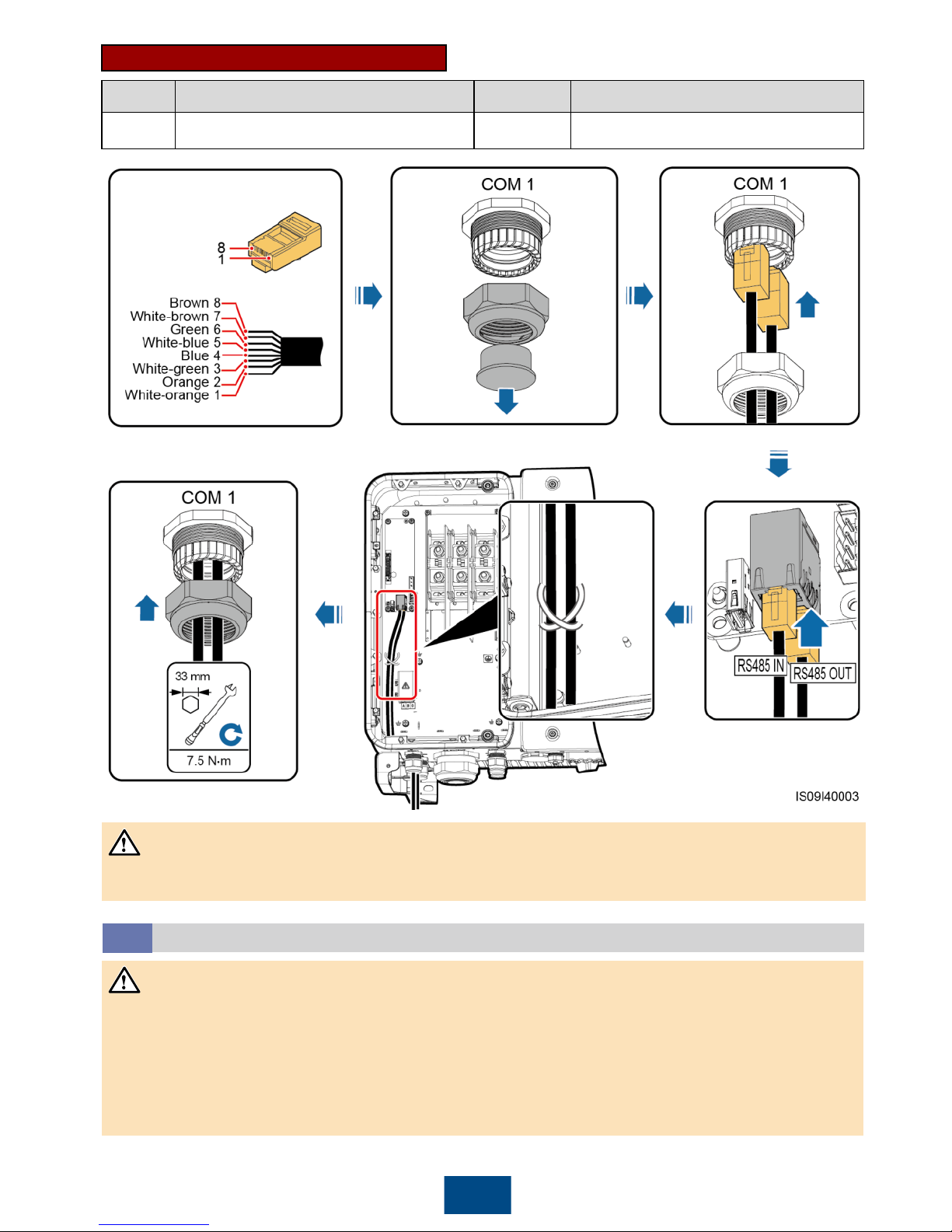
10
No.
Definition
No.
Definition
1, 4
RS485A, RS485 differential signal+
2, 5
RS485B, RS485 differential signal
–
Connecting to an RJ45 Network Port
After the RS485 communications cable is installed, seal the cable gland.
(Optional) Installing the Tracking System Power Cable
4.8
• The tracking system should be equipped with an overcurrent protective device/component. The
power cable between the device/component and wiring terminal should be no longer than 2.5 m.
• The tracking system is powered by the three-phase AC power grid with a rated voltage of 800 V.
• Keep inflammable materials away from the power cable.
• The power cable must be protected with a conduit to prevent short circuits caused by insulation
layer damage.
NOTICE
NOTICE
Page 12
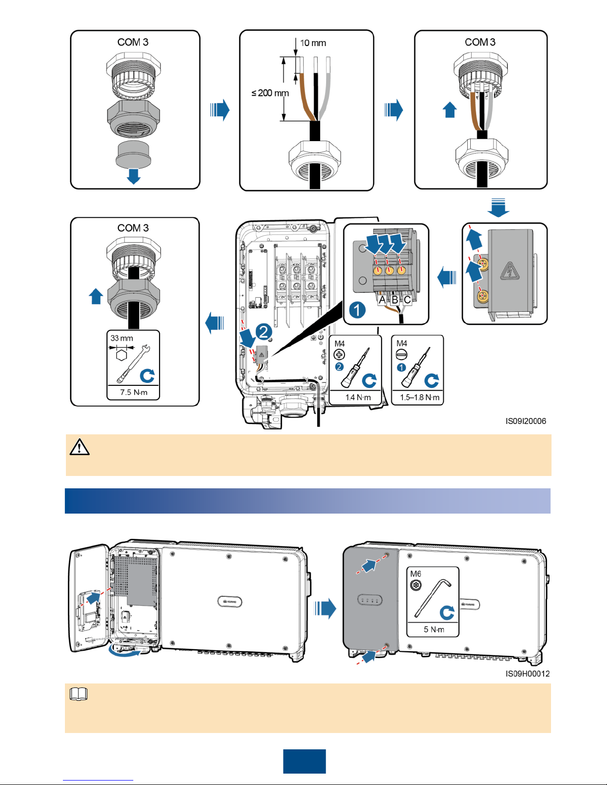
11
5
Closing the Maintenance Compartment Door
1. Install the cover and adjust the support bar. 2. Close the maintenance compartment door.
If the screws on the enclosure door are lost, obtain the spare screws from the fitting bag tied at
the enclosure bottom.
After the tracking system power cable is installed, seal the cable gland.
NOTICE
NOTE
Page 13
12
7
Powering On the System
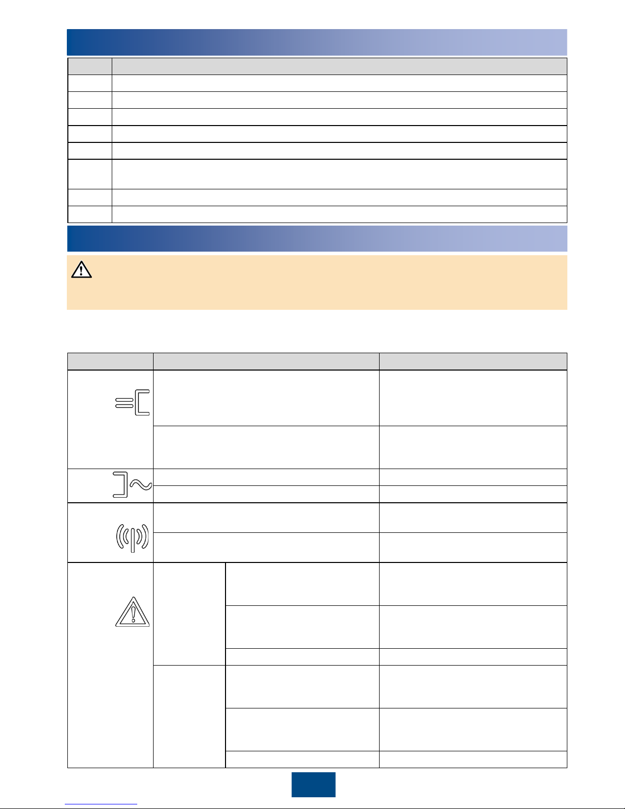
1. Turn on the AC switch between the SUN2000 and the power grid.
2. Turn the two DC switches at the bottom of the SUN2000 to the ON position.
3. Observe the LED indicators to check the SUN2000 operating status.
Before turning on the AC switch between the SUN2000 and the power grid, check that the AC
voltage is within the specified range using a multimeter.
Indicator
Status
Description
PV connection
indicator
Steady green
At least one PV string is properly
connected, and the DC input voltage
of the corresponding MPPT circuit is
at least 600 V.
Off
The SUN2000 disconnects from all
PV strings, or the DC input voltage of
each
MPPT
circuit is less than 600 V.
Grid
-tied
indicator
Steady green
The SUN2000 is in grid
-tied mode.
Off
The SUN2000 is not in grid-tied mode.
Communications
indicator
Blinking green
The SUN2000 receives data over
RS485 or PLC.
Off
The SUN2000 has not received data
over RS485 or PLC for 10 seconds.
Alarm/
Maintenance
indicator
Alarm status
The red indicator is blinking at
long intervals (on for 1s and
then off for 4s).
A warning alarm is generated.
The red indicator is blinking at
short intervals (on for 0.5s and
then off for 0.5s).
A minor alarm is generated.
Steady red
A major alarm is generated.
Local
maintenance
status
The green indicator is blinking
at long intervals (on for 1s and
then off for 1s).
Local maintenance is in progress.
The green indicator is blinking
at short intervals (on for
0.125s and then off for 0.125s).
Local maintenance failed.
Steady green
Local maintenance succeeded
.
6
Verifying Installation
No.
Acceptance Criteria
1
The SUN2000 is installed correctly and securely.
2
The DC switches and downstream AC switch are set to OFF.
3
All cables are connected correctly and securely.
4
Used cable glands are sealed and sealing nuts are tightened.
5
Unused terminals and ports are locked by watertight caps.
6
The installation space is proper, and the installation environment is clean and tidy, without
foreign matter.
7
The AC terminal cover is reinstalled.
8
The maintenance compartment door is closed and the door screws are tightened.
NOTICE
Page 14
13
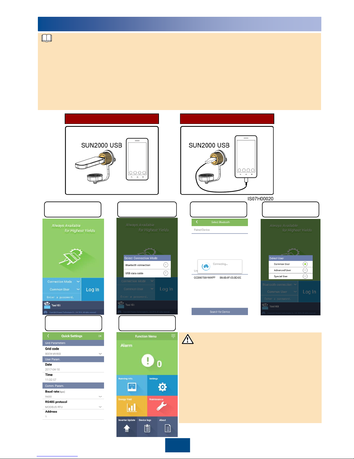
Login screen
Select a
connection method
Connect over
Bluetooth
Select a user
SUN2000 App
8
1. The SUN2000 app is mobile phone app that communicates with the SUN2000 over a USB data
cable or Bluetooth. As a convenient local monitoring and maintenance platform, it supports
querying alarms, configuring parameters, and performing routine maintenance. The app name is
SUN2000.
2. Requirements for the mobile phone operating system: Android 4.0 or later, iOS 7.0 or later.
3. Access the Huawei App Store (http://appstore.huawei.com), Google Play
(https://play.google.com), or App Store (iOS), search for SUN2000, and download the app
software package.
4. Connect a Bluetooth module or a USB data cable to the USB port of the SUN2000 to implement
the communication between the SUN2000 and the app.
iOS and Android
Android
Bluetooth connection USB data cable connection
NOTE
• The screenshots in this document correspond
to app 2.2.00.020 (Android).
• The preset password for Common User,
Advanced User, and Special User is
00000a. Use the preset password upon initial
login. To ensure account security, change the
password immediately after login.
• Set the correct grid code based on the
application area and scenario of the
SUN2000.
NOTICE
Quick settings Function menu
Page 15
9
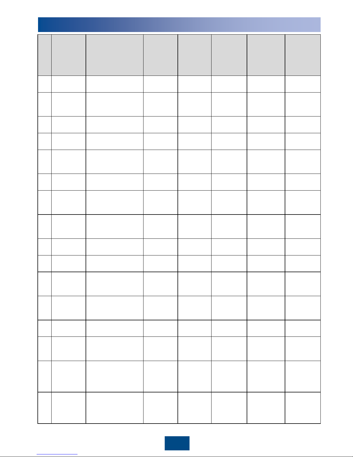
Grid Codes
14
No.
Grid Code
Description
SUN2000
-
90KTL
-H0
SUN2000
-
90KTL
-
H1/SUN20
00
-90KTL
-
H2
SUN2000
-
95KTL
-
INH0/SUN2
000-95KTLINH1
SUN2000
-
100KTL
-
H0/SUN200
0
-100KTL-
H2
SUN2000
-
100KTL
-
H1/SUN200
0
-105KTL-
H1
1
CHINA_MV
800
China medium
-
voltage power grid
N/A
N/A
N/A
Supported
N/A
2
G59
-
England
-
MV800
G59
medium-
voltage power grid
N/A
Supported
N/A
N/A
Supported
3
AS4777
-
MV800
Australia medium
-
voltage power grid
N/A
Supported
N/A
N/A
N/A
4
INDIA
-
MV800
India medium
-
voltage power grid
Supported
Supported
Supported
N/A
Supported
5
IEC61727
-
MV800
IEC61727
medium
voltage power grid
(50 Hz)
Supported
Supported
Supported
N/A
Supported
6
BDEW
-
MV800
Germany medium
-
voltage power grid
Supported
Supported
N/A
N/A
Supported
7
ABNT NBR
16149
-
MV800
Brazil medium
-
voltage power grid
N/A
N/A
N/A
N/A
Supported
8
UTE C 15
-
712
-1-
MV800
France medium
-
voltage power grid
N/A
N/A
N/A
N/A
Supported
9
Chile
-
MV800
Chile medium
-
voltage power grid
N/A
N/A
N/A
N/A
Supported
10
Mexico
-
MV800
Mexico medium
-
voltage power grid
N/A
N/A
N/A
N/A
Supported
11
TAI
-PEA-
MV800
Thailand PEA
medium
-voltage
power grid
N/A
Supported
N/A
N/A
N/A
12
PhilippinesMV800
Philippines
medium
-voltage
power grid
N/A
Supported
N/A
N/A
N/A
13
Malaysian
-
MV800
Malaysia medium
-
voltage power grid
N/A
Supported
N/A
N/A
N/A
14
SA_RPPs
-
MV800
South Africa
RPPs
medium
-voltage
power grid
N/A
Supported
N/A
N/A
Supported
15
Jordan
-
Transmissi
on
-MV800
Jordan power
transmission
network medium
-
voltage power grid
N/A
Supported
N/A
N/A
N/A
16
Jordan
-
Distribution
-MV800
Jordan power
distribution network
medium
-voltage
power grid
N/A
Supported
N/A
N/A
N/A
Page 16
15
No.
Grid Code
Description
SUN200090KTL-H0
SUN200090KTL
-
H1/SUN2
000
-
90KTL-H2
SUN200095KTL
-
INH0/SUN
2000
-
95KTL
-
INH1
SUN2000
-100KTLH0/SUN2
000
-
100KTL
-
H2
SUN2000100KTL
-
H1/SUN20
00
-
105KTL
-
H1
17
Egypt ETEC
-
MV800
Egypt medium-voltage
power grid
N/A
Supported
N/A
N/A
N/A
18
DUBAI
-
MV800
Dubai medium-voltage
power grid
N/A
Supported
N/A
N/A
Supported
19
SAUDI
-
MV800
Saudi Arabia medium
-
voltage power grid
Supported
Supported
N/A
N/A
N/A
20
CLC/TS50549
_IE
-MV800
Ireland medium-voltage
power grid
(CLC
/TS50549)
N/A
N/A
N/A
N/A
Supported
21
Northern
Ireland
-
MV800
Northern Ireland
medium-voltage power
grid
N/A
N/A
N/A
N/A
Supported
22
CEI0
-21-
MV800
Italy medium
-voltage
power grid (
CEI0-21)
N/A
N/A
N/A
N/A
Supported
23
IEC 61727
-
MV800
-60Hz
IEC61727
medium-
voltage power grid (60
Hz)
Supported
Supported
Supported
N/A
Supported
24
Pakistan
-
MV800
Pakistan medium
-
voltage power grid
N/A
Supported
N/A
N/A
N/A
25
BRASIL
-
ANEEL
-
MV800
Brazil medium
-voltage
power grid
N/A
N/A
N/A
N/A
Supported
26
Israel
-MV800
Israel medium
-voltage
power grid
N/A
Supported
N/A
N/A
N/A
27
CEI0
-16-
MV800
Italy medium
-voltage
power grid (
CEI0-16)
N/A
Supported
N/A
N/A
Supported
28
ZAMBIA
-
MV800
Zambia medium
-
voltage power grid
N/A
Supported
N/A
N/A
Supported
29
KENYA_ETHI
OPIA_MV800
Kenya and Ethiopia
medium-voltage power
grid
N/A
Supported
N/A
N/A
Supported
30
NAMIBIA_MV
800
Namibia medium
-
voltage power grid
N/A
Supported
N/A
N/A
Supported
31
Cameroon
-
MV800
Cameroon medium
-
voltage power grid
N/A
Supported
N/A
N/A
Supported
32
NIGERIA
-
MV800
Nigeria medium-voltage
power grid
N/A
Supported
N/A
N/A
Supported
33
ABUDHABI
-
MV800
Abu Dhabi medium
-
voltage power grid
N/A
Supported
N/A
N/A
Supported
34
LEBANON
-
MV800
Lebanon medium
-
voltage power grid
N/A
Supported
N/A
N/A
Supported
35
ARGENTINAMV800
Argentina medium
-
voltage power grid
N/A
N/A
N/A
N/A
Supported
Page 17
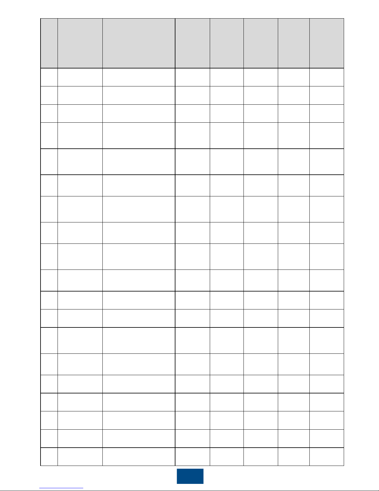
The grid codes are subject to change. The listed codes are for your reference only.
NOTE
No.
Grid Code
Description
SUN200090KTL-H0
SUN2000
-
90KTL
-
H1/SUN200
0
-90KTL-
H2
SUN200095KTL
-
INH0/SUN
2000
-
95KTL
-
INH1
SUN2000100KTL
-
H0/SUN2
000
-
100KTL
-
H2
SUN2000
-
100KTL
-
H1/SUN200
0
-105KTL-
H1
36
Jordan
-
TransmissionHV800
Jordan high
-
voltage power grid
N/A
Supported
N/A
N/A
N/A
37
TUNISIA
-
MV800
Tunisia medium
-
voltage power grid
N/A
Supported
N/A
N/A
Supported
38
AUSTRALIA
-
NER
-MV800
Australia
NER
medium
-voltage
power grid
N/A
Supported
N/A
N/A
N/A
39
VDE
-AR-
N4120_HV800
VDE4120 power
grid
Supported
Supported
N/A
N/A
Supported
40
IEEE 1547
-
MV800
IEEE 1547 power
grid
Supported
Supported
Supported
N/A
Supported
41
RD1699/661
-
MV800
Spain medium
-
voltage power grid
(RD1699/661)
N/A
N/A
N/A
N/A
Supported
42
PO12.3
-
MV800
Spain medium
-
voltage power grid
(PO12.3
)
N/A
N/A
N/A
N/A
Supported
43
Vietnam
-
MV800
Vietnam medium
-
voltage power grid
N/A
Supported
N/A
N/A
N/A
44
CHILE
-PMGD
-
MV800
Chile PMGD
medium
-voltage
power grid
N/A
N/A
N/A
N/A
Supported
45
GHANA
-
MV800
Ghana medium
-
voltage power grid
N/A
Supported
N/A
N/A
Supported
46
TAIPOWER
-
MV800
Taiwan power
medium
-voltage
power grid
N/A
Supported
N/A
N/A
N/A
47
OMAN-MV800
Oman medium
-
voltage power grid
N/A
Supported
N/A
N/A
Supported
48
KUWAIT
-
MV800
Kuwait medium
-
voltage power grid
N/A
Supported
N/A
N/A
Supported
49
BANGLADES
H
-MV800
Bangladesh
medium
-voltage
power grid
N/A
Supported
N/A
N/A
N/A
50
BAHRAIN
-
MV800
Bahrain medium
-
voltage power grid
N/A
Supported
N/A
N/A
Supported
51
KAZAKHSTAN
-MV800
Kazakhstan
medium
-voltage
power grid
N/A
N/A
N/A
N/A
Supported
52
Mauritius
-
MV800
Mauritius mediumvoltage power grid
N/A
N/A
N/A
N/A
Supported
16
Page 18

Huawei Technologies Co., Ltd.
Huawei Industrial Base, Bantian, Longgang
Shenzhen 518129 People's Republic of China
www.huawei.com
 Loading...