

SUN2000-(3KTL-10KTL)-M1
User Manual
Issue
02
Date
2020-11-20
HUAWEI TECHNOLOGIES CO., LTD.

Issue 02 (2020-11-20)
Copyright © Huawei Technologies Co.,
Ltd.
i
Copyright © Huawei Technologies Co., Ltd. 2021. All rights reserved.
No part of this document may be reproduced or transmitted in any form or by any means without prior
written consent of Huawei Technologies Co., Ltd.
Trademarks and Permissions
and other Huawei trademarks are trademarks of Huawei Technologies Co., Ltd.
All other trademarks and trade names mentioned in this document are the property of their respective
holders.
Notice
The purchased products, services and features are stipulated by the contract made between Huawei and
the customer. All or part of the products, services and features described in this document may not be
within the purchase scope or the usage scope. Unless otherwise specified in the contract, all statements,
information, and recommendations in this document are provided "AS IS" without warranties,
guarantees or representations of any kind, either express or implied.
The information in this document is subject to change without notice. Every effort has been made in the
preparation of this document to ensure accuracy of the contents, but all statements, information, and
recommendations in this document do not constitute a warranty of any kind, express or implied.
Huawei Technologies Co., Ltd.
Address:
Huawei Industrial Base
Bantian, Longgang
Shenzhen 518129
People's Republic of China
Website:
https://e.huawei.com

Issue 02 (2020-11-20)
Copyright © Huawei Technologies Co.,
Ltd.
ii
SUN2000-(3KTL-10KTL)-M1
User Manual
About This Document
Issue 02 (2020-11-20)
Copyright © Huawei Technologies Co.,
Ltd.
iii
Overview
Symbol
Description
Indicates a hazard with a high level of risk which, if not
avoided, will result in death or serious injury.
Indicates a hazard with a medium level of risk which, if
not avoided, could result in death or serious injury.
Indicates a hazard with a low level of risk which, if not
avoided, could result in minor or moderate injury.
About This Document
This document describes the SUN2000-3KTL-M1, SUN2000-4KTL-M1,
SUN2000-5KTL-M1, SUN2000-6KTL-M1, SUN2000-8KTL-M1, and
SUN2000-10KTL-M1 (SUN2000 for short) in terms of their installation, electrical
connections, commissioning, maintenance, and troubleshooting. Before installing
and operating the SUN2000, ensure that you are familiar with the features,
functions, and safety precautions provided in this document.
The SUN2000-8KTL-M1 and SUN2000-10KTL-M1 are not applicable to Australia.
Intended Audience
This document is applicable to:
Installers
Users
Symbol Conventions
The symbols that may be found in this document are defined as follows:
SUN2000-(3KTL-10KTL)-M1
User Manual
About This Document
Issue 02 (2020-11-20)
Copyright © Huawei Technologies Co.,
Ltd.
iv
Symbol
Description
Indicates a potentially hazardous situation which, if
not avoided, could result in equipment damage, data
loss, performance deterioration, or unanticipated
results.
Notice is used to address practices not related to
personal injury.
Supplements the important information in the main
text.
NOTE is used to address information not related to
personal injury, equipment damage, and environment
deterioration.
Change History
Changes between document issues are cumulative. The latest document issue
contains all the changes made in earlier issues.
Issue 02 (2020-11-20)
Updated 7.2.1.2 Battery Control.
Issue 01 (2020-09-30)
This issue is used for first office application (FOA).

SUN2000-(3KTL-10KTL)-M1
User Manual
Contents
Issue 02 (2020-11-20)
Copyright © Huawei Technologies Co.,
Ltd.
v
Contents
About This Document .................................................................................................................. iii
1 Safety Information ...................................................................................................................... 1
1.1 General Safety ........................................................................................................................................................... 1
1.2 Personnel Requirements .......................................................................................................................................... 2
1.3 Electrical Safety ......................................................................................................................................................... 3
1.4 Installation Environment Requirements ............................................................................................................... 4
1.5 Mechanical Safety ..................................................................................................................................................... 4
1.6 Commissioning .......................................................................................................................................................... 6
1.7 Maintenance and Replacement .............................................................................................................................. 6
2 Overview ........................................................................................................................................ 7
2.1 Product Introduction ................................................................................................................................................. 7
2.2 Appearance .............................................................................................................................................................. 11
2.3 Label Description ..................................................................................................................................................... 13
2.3.1 Enclosure Labels ................................................................................................................................................... 13
2.3.2 Product Nameplate .............................................................................................................................................. 15
2.4 Working Principles .................................................................................................................................................. 15
2.4.1 Circuit Diagram .................................................................................................................................................... 15
2.4.2 Working Modes .................................................................................................................................................... 16
3 Storage.......................................................................................................................................... 18
4 Installation .................................................................................................................................. 19
4.1 Checking Before Installation ................................................................................................................................. 19
4.2 Tools .......................................................................................................................................................................... 20
4.3 Determining the Installation Position ................................................................................................................. 21
4.3.1 Environment Requirements ................................................................................................................................ 21
4.3.2 Space Requirements ............................................................................................................................................ 22
4.4 Moving the SUN2000 ............................................................................................................................................. 25
4.5 Installing the Mounting Bracket........................................................................................................................... 26
4.5.1 Wall-mounted Installation ................................................................................................................................. 27
4.5.2 Support-mounted Installation ........................................................................................................................... 30

SUN2000-(3KTL-10KTL)-M1
User Manual
Contents
Issue 02 (2020-11-20)
Copyright © Huawei Technologies Co.,
Ltd.
vi
5 Electrical Connections .............................................................................................................. 34
5.1 Installation Preparation ......................................................................................................................................... 34
5.2 Connecting the PE cable ........................................................................................................................................ 37
5.3 Connecting the AC Output Power Cable ............................................................................................................ 40
5.4 Installing DC input power cables ......................................................................................................................... 44
5.5 (Optional) Connecting Battery Cables ................................................................................................................ 49
5.6 Install the Smart Dongle ........................................................................................................................................ 51
5.7 (Optional) Connecting the Signal Cable ............................................................................................................. 53
5.7.1 Connecting the RS485 Communications Cable (Inverter Cascading) ........................................................ 57
5.7.2 Connecting the RS485 Communications Cable (Smart Power Sensor) ..................................................... 58
5.7.3 Connecting an RS485 Communications Cable (Between a Power Meter and a Battery) ...................... 61
5.7.4 Connecting the Power Grid Scheduling Signal Cable .................................................................................... 62
5.7.5 Connecting a Signal Cable to the Smart Backup Box ................................................................................... 64
6 Commissioning ........................................................................................................................... 66
6.1 Checking Before Power-On ................................................................................................................................... 66
6.2 SUN2000 power-on ................................................................................................................................................ 67
7 Man-Machine Interaction ....................................................................................................... 73
7.1 App Commissioning ................................................................................................................................................ 73
7.1.1 Downloading the FusionSolar App ................................................................................................................... 73
7.1.2 (Optional) Registering an Installer Account ................................................................................................... 73
7.1.3 Creating a PV Plant and a User ......................................................................................................................... 75
7.1.4 (Optional) Setting the Physical Layout of the Smart PV Optimizers ......................................................... 75
7.1.5 Detect optimizer disconnection ......................................................................................................................... 78
7.2 Parameters Settings ................................................................................................................................................ 79
7.2.1 Energy Control ...................................................................................................................................................... 79
7.2.1.1 Grid-tied Point Control ..................................................................................................................................... 79
7.2.1.2 Battery Control .................................................................................................................................................. 83
7.2.2 AFCI ......................................................................................................................................................................... 86
7.2.3 IPS Check (for Italy CEI0-21 Grid Code Only) ................................................................................................. 88
7.3 SmartLogger Networking Scenario ...................................................................................................................... 90
8 Maintenance ............................................................................................................................... 91
8.1 SUN2000 Power-Off ............................................................................................................................................... 91
8.2 Routine Maintenance ............................................................................................................................................. 92
8.3 Troubleshooting ...................................................................................................................................................... 92
9 Handling the Inverter ............................................................................................................. 105
9.1 Removing the SUN2000 ....................................................................................................................................... 105
9.2 Packing the SUN2000 ................................................................................................................................ ........... 105

SUN2000-(3KTL-10KTL)-M1
User Manual
Contents
Issue 02 (2020-11-20)
Copyright © Huawei Technologies Co.,
Ltd.
vii
9.3 Disposing of the SUN2000 .................................................................................................................................. 105
10 Technical Specifications ....................................................................................................... 106
10.1 SUN2000 Technical Specifications ........................................................................................................................ 106
10.2 LUNA2000-5KW-C0 ............................................................................................................................................. 112
10.3 LUNA2000-5-E0 .................................................................................................................................................... 113
10.4 Optimizer Technical Specifications ........................................................................................................................ 114
A Grid Code .................................................................................................................................. 117
B Device Commissioning ........................................................................................................... 119
C Resetting Password ................................................................................................................ 123
D DRM Configuration Guide for Standard As NZS4777.2 .............................................. 127
E Rapid Shutdown ...................................................................................................................... 127
F Locating Insulation Resistance Faults ............................................................................... 129
G Acronyms and Abbreviations .............................................................................................. 133

SUN2000-(3KTL-10KTL)-M1
User Manual
1 Safety Information
Issue 02 (2020-11-20)
Copyright © Huawei Technologies Co.,
Ltd.
1
1.1 General Safety
Statement
Before installing, operating, and maintaining the equipment, read this document
and observe all the safety instructions on the equipment and in this document.
1 Safety Information
The "NOTICE", "CAUTION", "WARNING", and "DANGER" statements in this
document do not cover all the safety instructions. They are only supplements to the
safety instructions. Huawei will not be liable for any consequence caused by the
violation of general safety requirements or design, production, and usage safety
standards.
Ensure that the equipment is used in environments that meet its design
specifications. Otherwise, the equipment may become faulty, and the resulting
equipment malfunction, component damage, personal injuries, or property damage
are not covered under the warranty.
Follow local laws and regulations when installing, operating, or maintaining the
equipment. The safety instructions in this document are only supplements to local
laws and regulations.
Huawei will not be liable for any consequences of the following circumstances:
Operation beyond the conditions specified in this document
Installation or use in environments which are not specified in relevant
international or national standards
Unauthorized modifications to the product or software code or removal of the
product
Failure to follow the operation instructions and safety precautions on the
product and in this document
Equipment damage due to force majeure, such as earthquakes, fire, and storms
Damage caused during transportation by the customer
SUN2000-(3KTL-10KTL)-M1
User Manual
1 Safety Information
Issue 02 (2020-11-20)
Copyright © Huawei Technologies Co.,
Ltd.
2
Storage conditions that do not meet the requirements specified in this
document
General Requirements
Do not work with power on during installation.
Do not install, use, or operate outdoor equipment and cables (including but not
limited to moving equipment, operating equipment and cables, inserting
connectors to or removing connectors from signal ports connected to outdoor
facilities, working at heights, and performing outdoor installation) in harsh
weather conditions such as lightning, rain, snow, and level 6 or stronger wind.
After installing the equipment, remove idle packing materials such as cartons,
foam, plastics, and cable ties from the equipment area.
In the case of a fire, immediately leave the building or the equipment area, and
turn on the fire alarm bell or make an emergency call. Do not enter the
building on fire in any case.
Do not scrawl, damage, or block any warning label on the equipment.
Tighten the screws using tools when installing the equipment.
Understand the components and functioning of a grid-tied PV power system
and relevant local standards.
Repaint any paint scratches caused during equipment transportation or
installation in a timely manner. Equipment with scratches cannot be exposed to
an outdoor environment for a long period of time.
Do not open the host panel of the equipment.
Personal Safety
If there is a probability of personal injury or equipment damage during
operations on the equipment, immediately stop the operations, report the case
to the supervisor, and take feasible protective measures.
Use tools correctly to avoid hurting people or damaging the equipment.
Do not touch the energized equipment, as the enclosure is hot.
1.2 Personnel Requirements
Personnel who plan to install or maintain Huawei equipment must receive
thorough training, understand all necessary safety precautions, and be able to
correctly perform all operations.
Only qualified professionals or trained personnel are allowed to install, operate,
and maintain the equipment.
SUN2000-(3KTL-10KTL)-M1
User Manual
1 Safety Information
Issue 02 (2020-11-20)
Copyright © Huawei Technologies Co.,
Ltd.
3
Only qualified professionals are allowed to remove safety facilities and inspect
the equipment.
Personnel who will operate the equipment, including operators, trained
personnel, and professionals, should possess the local national required
qualifications in special operations such as high-voltage operations, working at
heights, and operations of special equipment.
Only professionals or authorized personnel are allowed to replace the
equipment or components (including software).
Professionals: personnel who are trained or experienced in equipment operations and are
clear of the sources and degree of various potential hazards in equipment installation,
operation, and maintenance
Trained personnel: personnel who are technically trained, have required experience, are
aware of possible hazards on themselves in certain operations, and are able to take
protective measures to minimize the hazards on themselves and other people
Operators: operation personnel who may come in contact with the equipment, except
trained personnel and professionals
1.3 Electrical Safety
Grounding
For the equipment that needs to be grounded, install the ground cable first
when installing the equipment and remove the ground cable last when
removing the equipment.
Do not damage the ground conductor.
Do not operate the equipment in the absence of a properly installed ground
conductor.
Ensure that the equipment is connected permanently to the protective ground.
Before operating the equipment, check its electrical connection to ensure that it
is securely grounded.
General Requirements
Before connecting cables, ensure that the equipment is intact. Otherwise, electric
shocks or fire may occur.
Ensure that all electrical connections comply with local electrical standards.
Obtain approval from the local electric utility company before using the
equipment in grid-tied mode.
Ensure that the cables you prepared meet local regulations.
SUN2000-(3KTL-10KTL)-M1
User Manual
1 Safety Information
Issue 02 (2020-11-20)
Copyright © Huawei Technologies Co.,
Ltd.
4
AC and DC Power
Do not connect or disconnect power cables with power on. Transient contact
between the core of the power cable and the conductor will generate electric arcs or
sparks, which may cause fire or personal injury.
Use dedicated insulated tools when performing high-voltage operations.
Before making electrical connections, switch off the disconnector on the
upstream device to cut off the power supply if people may contact energized
components.
Before connecting a power cable, check that the label on the power cable is
correct.
If the equipment has multiple inputs, disconnect all the inputs before operating
the equipment.
Cabling
When routing cables, ensure that a distance of at least 30 mm exists between
the cables and heat-generating components or areas. This prevents damage to
the insulation layer of the cables.
Bind cables of the same type together. When routing cables of different types,
ensure that they are at least 30 mm away from each other.
Ensure that the cables used in a grid-tied PV power system are properly
connected and insulated and meet specifications.
1.4 Installation Environment Requirements
Ensure that the equipment is installed in a well ventilated environment.
To prevent fire due to high temperature, ensure that the ventilation vents or
heat dissipation system are not blocked when the equipment is running.
Do not expose the equipment to flammable or explosive gas or smoke. Do not
perform any operation on the equipment in such environments.
1.5 Mechanical Safety
Using Ladders
Use wooden or fiberglass ladders when you need to perform live working at
heights.
SUN2000-(3KTL-10KTL)-M1
User Manual
1 Safety Information
Issue 02 (2020-11-20)
Copyright © Huawei Technologies Co.,
Ltd.
5
When a step ladder is used, ensure that the pull ropes are secured and the
ladder is held firm.
Before using a ladder, check that it is intact and confirm its load bearing
capacity. Do not overload it.
Ensure that the wider end of the ladder is at the bottom, or protective
measures have been taken at the bottom to prevent the ladder from sliding.
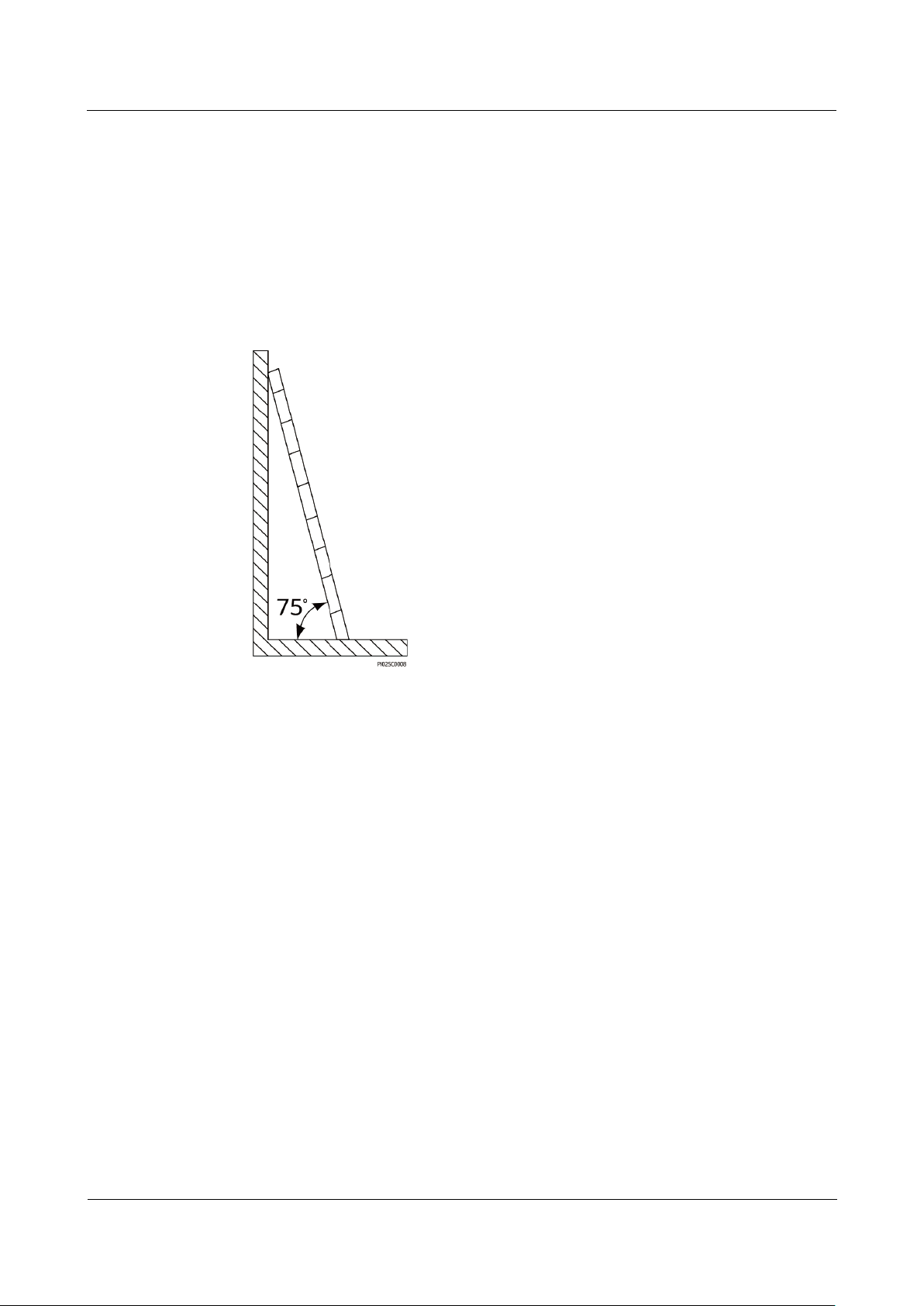
Ensure that the ladder is securely positioned. The recommended angle for a
ladder against the floor is 75 degrees, as shown in the following figure. An
angle rule can be used to measure the angle.
When climbing a ladder, take the following precautions to reduce risks and
ensure safety:
− Keep your body steady.
− Do not climb higher than the fourth rung of the ladder from the top.
− Ensure that your body's center of gravity does not shift outside the legs of
the ladder.
Drilling Holes
When drilling holes into a wall or floor, observe the following safety precautions:
Wear goggles and protective gloves when drilling holes.
When drilling holes, protect the equipment from shavings. After drilling, clean
up any shavings that have accumulated inside or outside the equipment.
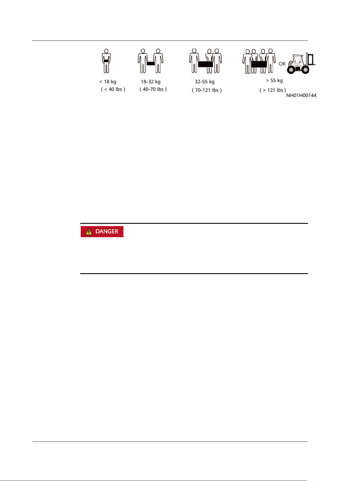
Moving Heavy Objects
Be cautious to avoid injury when moving heavy objects.
SUN2000-(3KTL-10KTL)-M1
User Manual
1 Safety Information
Issue 02 (2020-11-20)
Copyright © Huawei Technologies Co.,
Ltd.
6
When moving the equipment by hand, wear protective gloves to prevent
injuries.
1.6 Commissioning
When the equipment is powered on for the first time, ensure that professional
personnel set parameters correctly. Incorrect settings may result in inconsistency
with local certification and affect the normal operation of the equipment.
1.7 Maintenance and Replacement
High voltage generated by the equipment during operation may cause an electric
shock, which could result in death, serious injury, or serious property damage. Prior
to maintenance, power off the equipment and strictly comply with the safety
precautions in this document and relevant documents.
Maintain the equipment with sufficient knowledge of this document and using
proper tools and testing equipment.
Before maintaining the equipment, power it off and follow the instructions on
the delayed discharge label to ensure that the equipment is powered off.
Place temporary warning signs or erect fences to prevent unauthorized access
to the maintenance site.
If the equipment is faulty, contact your dealer.
The equipment can be powered on only after all faults are rectified. Failing to
do so may escalate faults or damage the equipment.
SUN2000-(3KTL-10KTL)-M1
User Manual
2 Overview
Issue 02 (2020-11-20)
Copyright © Huawei Technologies Co.,
Ltd.
7
2.1 Product Introduction
Functions
The SUN2000 inverter is a three-phase grid-tied PV string inverter that converts the
DC power generated by PV strings into AC power and feeds the power into the
power grid.
2 Overview
Model
This document covers the following SUN2000 models:
SUN2000-3KTL-M1
SUN2000-4KTL-M1
SUN2000-5KTL-M1
SUN2000-6KTL-M1
SUN2000-8KTL-M1
SUN2000-10KTL-M1
The SUN2000-8KTL-M1 and SUN2000-10KTL-M1 are not applicable to Australia.
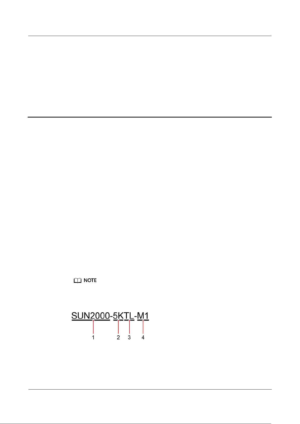
Figure 2-1 Model description (using SUN2000-5KTL-M1 as an example)
SUN2000-(3KTL-10KTL)-M1
User Manual
2 Overview
Issue 02 (2020-11-20)
Copyright © Huawei Technologies Co.,
Ltd.
8
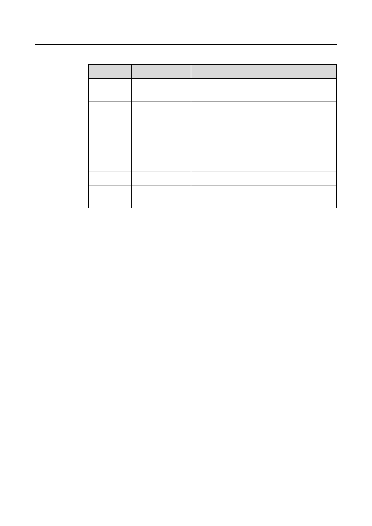
Table 2-1 Model description
Identifier
Description
Value
1
Series name
SUN2000: three-phase grid-tied PV string
inverter
2
Power class
3K: rated power of 3 kW
4K: rated power of 4 kW
5K: rated power of 5 kW
6K: rated power of 6 kW
8K: rated power of 8 kW
10K: rated power of 10 kW
3
Topology
TL: transformerless
4
Product code
M1: product series with an input voltage level
of 1100 V DC
Networking Application
The SUN2000 applies to residential rooftop grid-tied systems and small-sized
ground PV plant grid-tied systems. Typically, a grid-tied system consists of PV
strings, grid-tied inverters, AC switches, and power distribution units.

SUN2000-(3KTL-10KTL)-M1
User Manual
2 Overview
Issue 02 (2020-11-20)
Copyright © Huawei Technologies Co.,
Ltd.
9
Figure 2-2 Networking application (dashed boxes indicate optional components)
If the built-in WiFi module of the SUN2000 connects to the app, only device
commissioning can be performed.
In the SUN2000 cascading scenario, the master inverter model can be
SUN2000-(3KTL-10KTL)-M1, and the slave inverter model can be
SUN2000-(3KTL-10KTL)-M1, SUN2000-(5KTL–20KTL)-M0,
SUN2000-50KTL/60KTL/65KTL-M0, SUN2000-29.9KTL/36KTL, or SUN2000-33KTL-A.
Supported Power Grid Types
The SUN2000 supports TN-S, TN-C, TN-C-S, TT, and IT power grids.

SUN2000-(3KTL-10KTL)-M1
User Manual
2 Overview
Issue 02 (2020-11-20)
Copyright © Huawei Technologies Co.,
Ltd.
10
Figure 2-3 Power grid types
When the SUN2000 is used in the TT power grid, the N-to-PE voltage must be less than 30
V.
When the SUN2000 is used in the IT power grid, set Isolation to Input ungrounded, with
TF.
SUN2000-(3KTL-10KTL)-M1
User Manual
2 Overview
Issue 02 (2020-11-20)
Copyright © Huawei Technologies Co.,
Ltd.
11
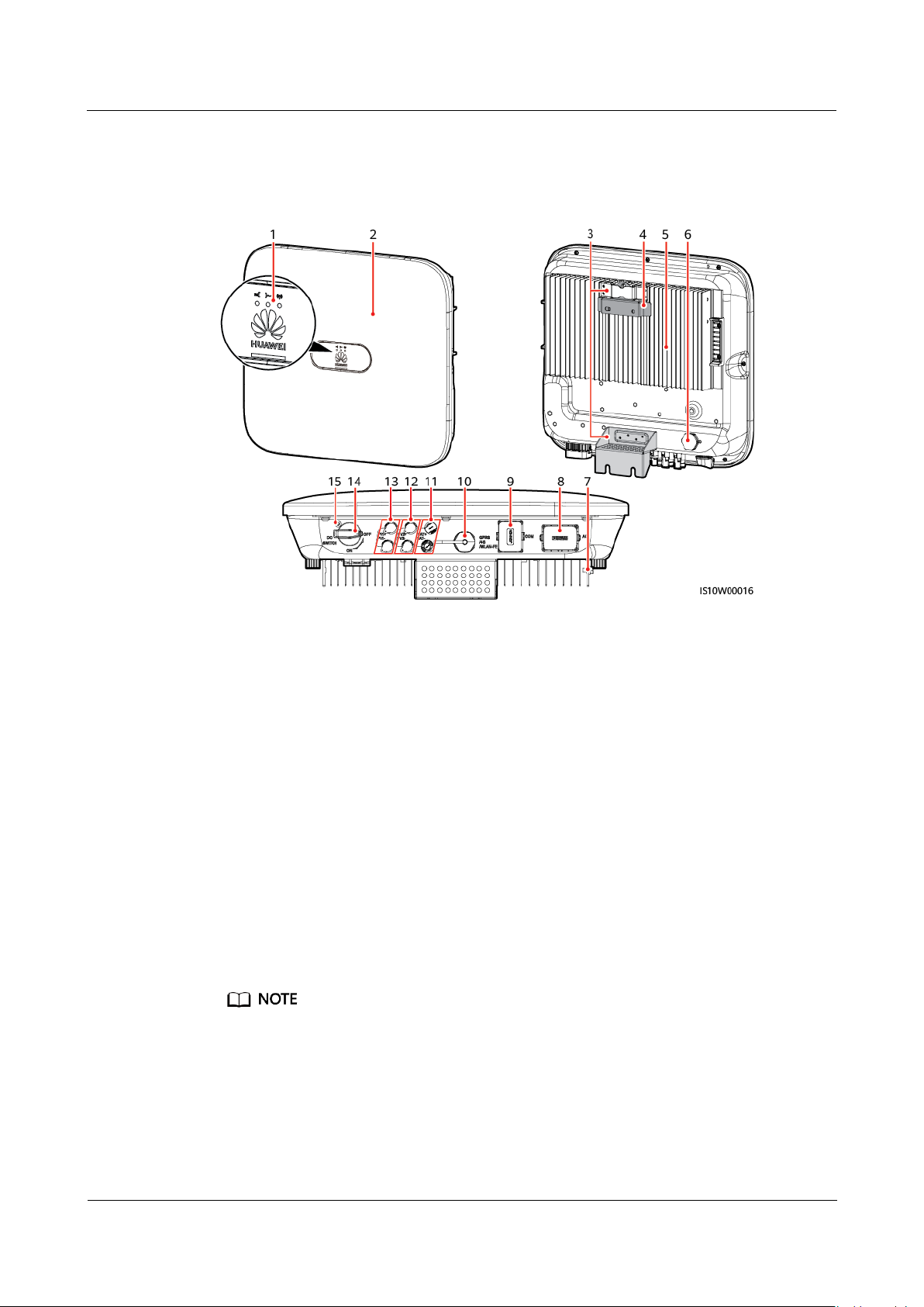
2.2 Appearance
(1) LED indicator
(2) Front panel
(3) Hanging kit
(4) Mounting bracket
(5) Heat sink
(6) Ventilation valve
(7) Ground screw
(8) AC output port (AC)
(9) Communications port (COM)
(10) Smart Dongle port
(GPRS/4G/WLAN-FE)
(11) Battery terminals (BAT+/BAT–)
(12) DC input terminals (PV2+/PV2–)
(13) DC input terminals (PV1+/PV1–)
(14) DC switch (DC SWITCH)
(15) Hole for the DC switch locking screw
Figure 2-4 Appearance
Two M6 screw holes are reserved on the left and right sides of the SUN2000 for installing the
awning.
SUN2000-(3KTL-10KTL)-M1
User Manual
2 Overview
Issue 02 (2020-11-20)
Copyright © Huawei Technologies Co.,
Ltd.
12
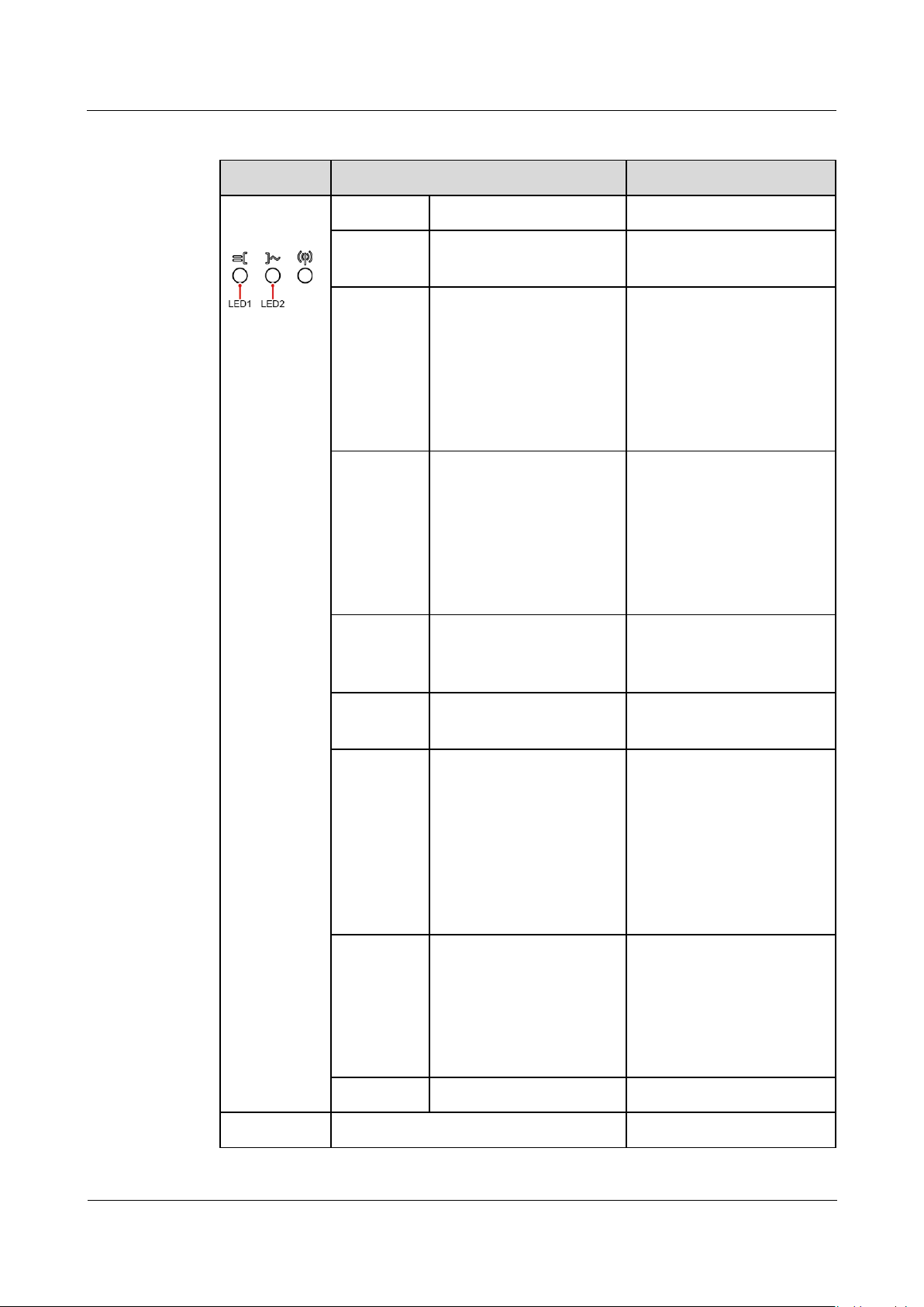
Category
Status
Description
Running
indicator
LED1
LED2
-
Steady
green
Steady green
The SUN2000 is operating
in grid-tied mode.
Blinking
green at
long
intervals
(on for 1s
and then
off for 1s)
Off
The DC is on and the AC is
off.
Blinking
green at
long
intervals
(on for 1s
and then
off for 1s)
Blinking green at long
intervals (on for 1s and
then off for 1s)
Both the DC and AC are
on, and the SUN2000 is
not supplying power to
the power grid.
Off
Blinking green at long
intervals (on for 1s and
then off for 1s)
The DC is off and the AC
is on.
Off
Off
Both the DC and AC are
off.
Blinking
red at
short
intervals
(on for
0.2s and
then off
for 0.2s)
-
DC environment alarm.
For example, the input
voltage of the PV string is
high, the PV string is
reversely connected, or
the insulation resistance
is low.
-
Blinking red at short
intervals
AC environment alarm.
For example, the power
grid is undervoltage,
overvoltage,
overfrequency, or
underfrequency.
Steady red
Steady red
Fault
Communica
LED3
-
Table 2-2 Indicator description
SUN2000-(3KTL-10KTL)-M1
User Manual
2 Overview
Issue 02 (2020-11-20)
Copyright © Huawei Technologies Co.,
Ltd.
13
Category
Status
Description
tions
indicator
Blinking green at short intervals (on
for 0.2s and then off for 0.2s)
Communication is in
progress. (When a mobile
phone is connected to the
SUN2000, the indicator
blinks green at long
intervals, indicating that
the phone is connected to
the SUN2000.)
Blinking green at long intervals (on
for 1s and then off for 1s)
Mobile phone access
Off
No communication
Device
replacement
indicator
LED1
LED2
LED3
–
Steady red
Steady red
Steady red
The SUN2000 hardware is
faulty and the SUN2000
needs to be replaced.
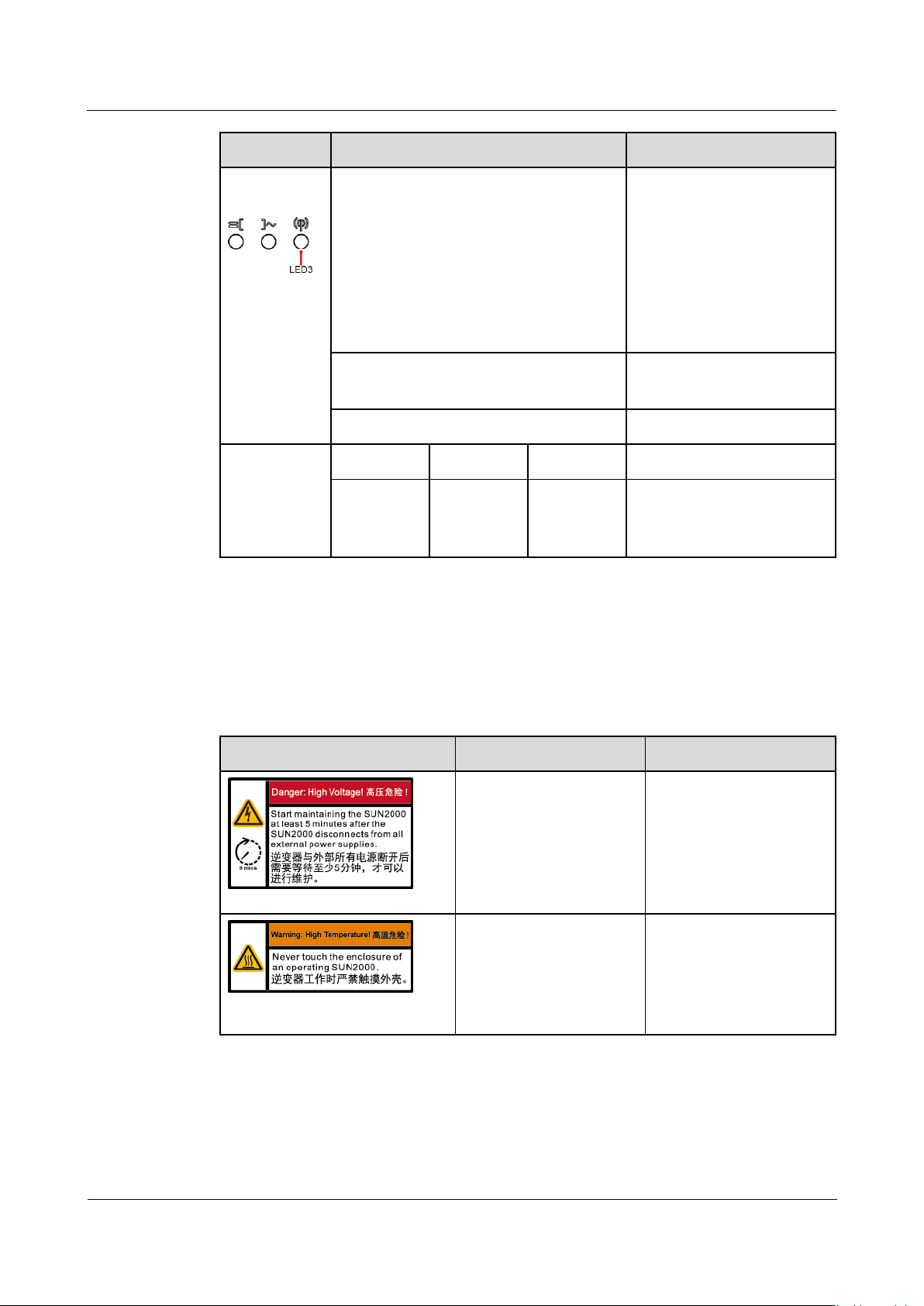
Symbol
Name
Description
Delay discharge
Residual voltage exists
after the SUN2000 is
powered off. It takes 5
minutes for the
SUN2000 to discharge
to the safe voltage.
Burn warning
Do not touch a running
SUN2000 because it
generates high
temperatures on the
shell.
2.3 Label Description
2.3.1 Enclosure Labels
SUN2000-(3KTL-10KTL)-M1
User Manual
2 Overview
Issue 02 (2020-11-20)
Copyright © Huawei Technologies Co.,
Ltd.
14
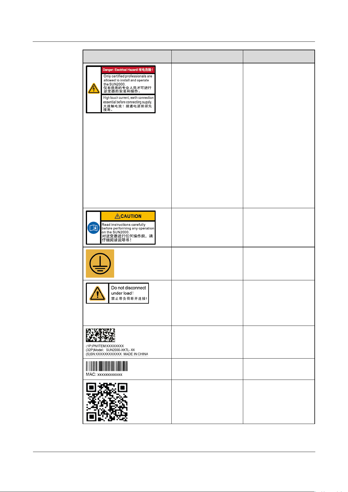
Symbol
Name
Description
Electric shock warning
High voltage exists
after the SUN2000
is powered on. Only
qualified and
trained electrical
technicians are
allowed to perform
operations on the
SUN2000.
High touch current
exists after the
SUN2000 is
powered on. Before
powering on the
SUN2000, ensure
that the SUN2000 is
properly grounded.
Refer to
documentation
Reminds operators to
refer to the documents
delivered with the
SUN2000.
Grounding label
Indicates the position
for connecting the PE
cable.
Operation warning
Do not remove the DC
input connector or AC
output connector when
the SUN2000 is
running.
SUN2000 serial
number
Indicates the serial
number.
SUN2000 MAC address
Indicates the MAC
address.
SUN2000 WiFi login
QR code
Scan the QR code to
connect to the Huawei
SUN2000 WiFi
network.
SUN2000-(3KTL-10KTL)-M1
User Manual
2 Overview
Issue 02 (2020-11-20)
Copyright © Huawei Technologies Co.,
Ltd.
15
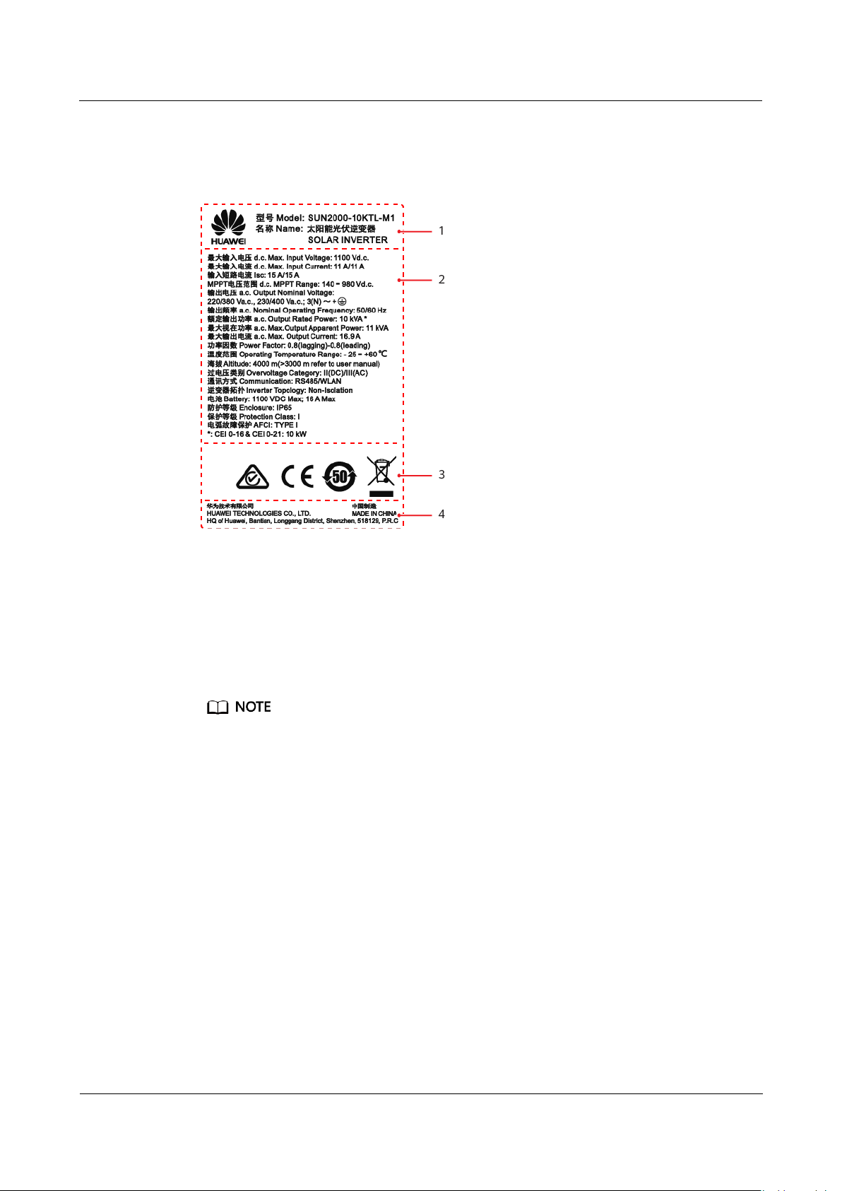
2.3.2 Product Nameplate
(1) Trademark and product model
(2) Key technical parameters
(3) Certification marks
(4) Company name and country of
origin
Figure 2-5 Nameplate (using SUN2000-10KTL-M1 as an example)
The nameplate figure is for reference only.
2.4 Working Principles
2.4.1 Circuit Diagram
Two PV strings connect to the SUN2000, and their maximum power points are
tracked by two maximum power point tracking (MPPT) circuits. The SUN2000
converts DC power into three-phase AC power through an inverter circuit. Surge
protection is supported on both the DC and AC sides.
SUN2000-(3KTL-10KTL)-M1
User Manual
2 Overview
Issue 02 (2020-11-20)
Copyright © Huawei Technologies Co.,
Ltd.
16
Figure 2-6 SUN2000 conceptual diagram
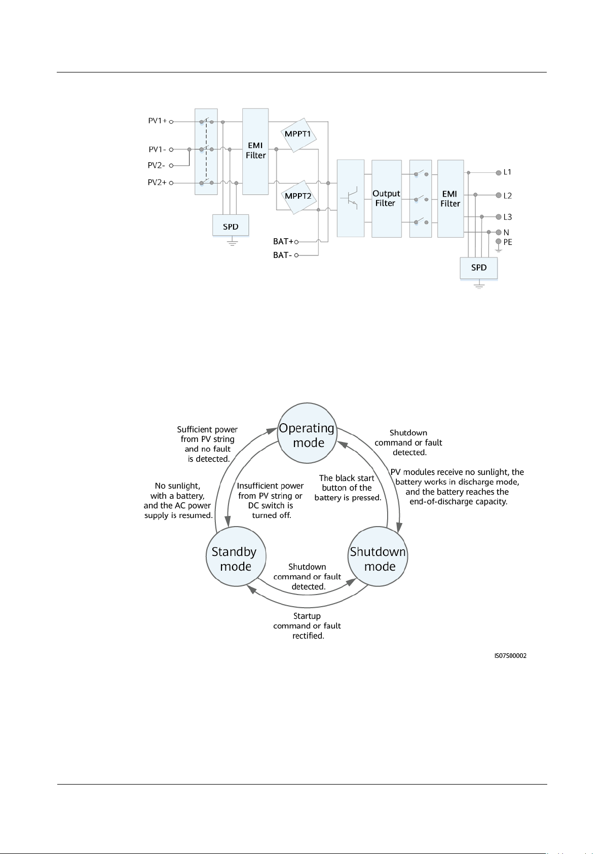
2.4.2 Working Modes
The SUN2000 can work in Standby, Operating, or Shutdown mode.
Figure 2-7 Working modes
SUN2000-(3KTL-10KTL)-M1
User Manual
2 Overview
Issue 02 (2020-11-20)
Copyright © Huawei Technologies Co.,
Ltd.
17
Table 2-3 Working mode description
Working
Mode
Description
Standby
The SUN2000 enters Standby mode when the external environment
does not meet the operating requirements. In Standby mode:
The SUN2000 continuously performs status check and enters the
Operating mode once the operating requirements are met.
The SUN2000 enters Shutdown mode after detecting a shutdown
command or a fault after startup.
Operating
In Operating mode:
The SUN2000 converts DC power from PV strings into AC power
and feeds the power to the power grid.
The SUN2000 tracks the maximum power point to maximize the
PV string output.
If the SUN2000 detects a fault or a shutdown command, it enters
the Shutdown mode.
The SUN2000 enters Standby mode after detecting that the PV
string output power is not suitable for connecting to the power
grid for generating power.
If the PV modules receive no sunlight, the battery works in
discharge mode, and the battery reaches the end-of-discharge
capacity, the SUN2000 enters Shutdown mode.
Shutdown
In Standby or Operating mode, the SUN2000 enters Shutdown
mode after detecting a fault or shutdown command.
In Shutdown mode, the SUN2000 enters Standby mode after
detecting a startup command or that the fault is rectified.
In Shutdown mode, if the black start button of the battery is
pressed, the SUN2000 enters Operating mode.

SUN2000-(3KTL-10KTL)-M1
User Manual
3 Storage
Issue 02 (2020-11-20)
Copyright © Huawei Technologies Co.,
Ltd.
18
3 Storage
The following requirements should be met if the SUN2000 is not put into use
directly:
Do not unpack the SUN2000.
Keep the storage temperature at –40°C to +70°C and the humidity at 5%–95%
RH.
The SUN2000 should be stored in a clean and dry place and be protected from
dust and water vapor corrosion.
A maximum of eight SUN2000s can be stacked. To avoid personal injury or
device damage, stack SUN2000s with caution to prevent them from falling
over.
Periodic inspections are required during the storage. Replace the packing
materials if necessary.
If the SUN2000 has been long-term stored, inspections and tests should be
conducted by qualified personnel before it is put into use.

SUN2000-(3KTL-10KTL)-M1
User Manual
4 Installation
Issue 02 (2020-11-20)
Copyright © Huawei Technologies Co.,
Ltd.
19
4.1 Checking Before Installation
Outer Packing Materials
Before unpacking the inverter, check the outer packing materials for damage, such
as holes and cracks, and check the inverter model. If any damage is found or the
inverter model is not what you requested, do not unpack the package and contact
your supplier as soon as possible.
4 Installation
You are advised to remove the packing materials within 24 hours before installing the
inverter.
Package Contents
After unpacking the inverter, check that the contents are intact and complete. If any
damage is found or any component is missing, contact your supplier.
For details about the number of contents, see the
Packing List
in the packing case.
SUN2000-(3KTL-10KTL)-M1
User Manual
4 Installation
Issue 02 (2020-11-20)
Copyright © Huawei Technologies Co.,
Ltd.
20
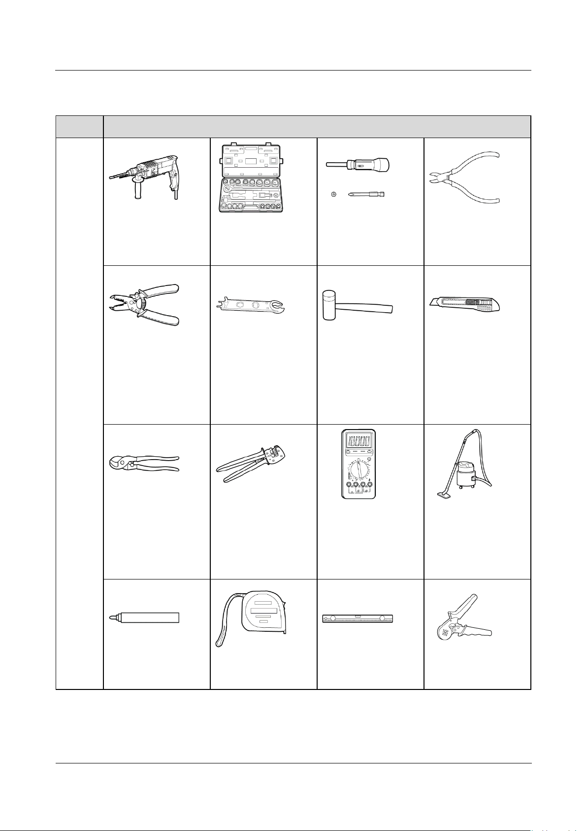
Type
Tool
Installa
tion
Tools
Hammer drill
Drill bit: Φ8 mm and
Φ6 mm
Socket wrench set
Torque screwdriver
Phillips head: M3
Diagonal pliers
Wire stripper
Removal wrench
Model: PV-MS-HZ
Open-end Wrench;
manufacturer:
Staubli
Rubber mallet
Utility knife
Cable cutter
Crimping tool
Model:
PV-CZM-22100;
manufacturer:
Staubli
Multimeter
DC voltage
measurement range
≥ 1100 V DC
Vacuum cleaner
Marker
Measuring tape
Bubble or digital
level
Cord end terminal
crimper
4.2 Tools

SUN2000-(3KTL-10KTL)-M1
User Manual
4 Installation
Issue 02 (2020-11-20)
Copyright © Huawei Technologies Co.,
Ltd.
21
Type
Tool
Heat shrink tubing
Heat gun
Cable tie
Hydraulic pliers
PPE
Safety gloves
Safety goggles
Anti-dust respirator
Safety shoes
4.3 Determining the Installation Position
4.3.1 Environment Requirements
Basic Requirements
The SUN2000 is protected to IP65 and can be installed indoors or outdoors.
Do not install the SUN2000 in a place where personnel are easy to come into
contact with its enclosure and heat sinks, because these parts are extremely hot
during operation.
Do not install the SUN2000 in areas with flammable or explosive materials.
Do not install the SUN2000 at a place within children's reach.
Do not install the SUN2000 outdoors in salt areas because it will be corroded
there and may cause fire. A salt area refers to the region within 500 meters
from the coast or prone to sea breeze. The regions prone to sea breeze vary
depending on weather conditions (such as typhoons and monsoons) or terrains
(such as dams and hills).
The SUN2000 must be installed in a well-ventilated environment to ensure
good heat dissipation.
Recommended: Install the SUN2000 in a sheltered place or a place with an
awning.
Mounting Structure Requirements
The mounting structure where the SUN2000 is installed must be fireproof.
Do not install the SUN2000 on flammable building materials.

SUN2000-(3KTL-10KTL)-M1
User Manual
4 Installation
Issue 02 (2020-11-20)
Copyright © Huawei Technologies Co.,
Ltd.
22
The SUN2000 is heavy. Ensure that the installation surface is solid enough to
bear the weight load.
In residential areas, do not install the SUN2000 on drywalls or walls made of
similar materials which have a weak sound insulation performance because the
noise generated by the SUN2000 is noticeable.
4.3.2 Space Requirements
Installation Angle Requirements
The SUN2000 can be wall-mounted or pole-mounted. The installation angle
requirements are as follows:
Install the SUN2000 vertically or at a maximum back tilt of 15 degrees to
facilitate heat dissipation.
Do not install the SUN2000 at forward tilted, excessive back tilted, side tilted,
horizontal, or upside down positions.
Figure 4-1 Installation tilts
Installation Space Requirements
Reserve enough space around the SUN2000 to ensure sufficient space for
installation and heat dissipation.
 Loading...