

Page 1
HUAWEI TECHNOLOGIES CO., LTD.
SUN2000-(33KTL, 36KTL, 40KTL)-US
Quick Guide (Mounting Bracket
Supplied with the SUN2000,
Amphenol Helios H4)
Issue: 03
Part Number: 31508086
Date: 2017-11-06
Page 2
Copyright © Huawei Technologies Co., Ltd. 2017. All rights reserved.
1
1
Product Overview
1. The information in this document is subject to change without notice. Every effort has been
made in the preparation of this document to ensure accuracy of the contents, but all
statements, information, and recommendations in this document do not constitute a warranty
of any kind, express or implied.
2. Before device installation, carefully read the SUN2000-(33KTL, 36KTL, 40KTL)-US User
Manual. You can log in to http://support.huawei.com/carrier/, and search for SUN2000 on the
Product Support tab page to view or obtain the user manual.
3. Only qualified and trained electrical technicians are allowed to operate the device. Operators
should understand the components and functioning of a grid-tied PV power system and be
familiar with relevant local standards.
4. Before installing the device, check that deliverables are intact and complete against the
packing list. If any damage is found or any component is missing, contact the dealer.
5. Use insulated tools when installing the device. For personal safety, wear insulation gloves and
protective shoes.
6. Huawei shall not be liable for any consequence caused by violation of the storage,
transportation, installation, and operation regulations specified in this document and the user
manual.
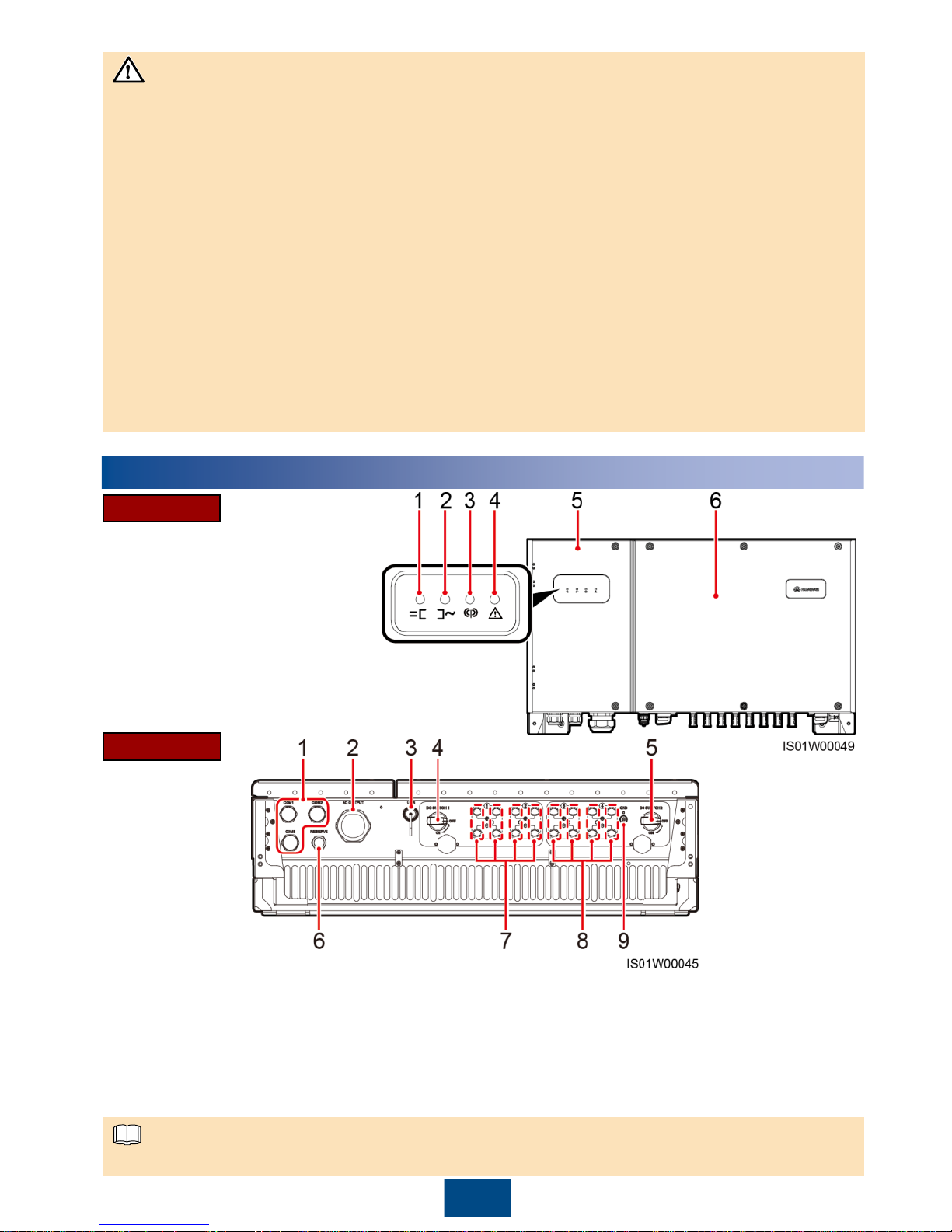
Waterproof cable connector is abbreviated as waterproof connector in the following text.
(1) PV connection indicator
(2) Grid-tied indicator
(3) Communication indicator
(4) Alarm/Maintenance indicator
(5) Maintenance compartment door
(6) Host panel
Front View
Ports
(1) 3/4-inch waterproof cable connectors
(COM1, COM2, and COM3)
(2) 2-inch waterproof cable connector (AC OUTPUT)
(3) USB port (USB) (4) DC switch 1 (DC SWITCH 1)
(5) DC switch 2 (DC SWITCH 2) (6) 1/2-inch waterproof cable connector (RESERVE)
(7) DC input terminals (controlled by DC
SWITCH 1)
(8) DC input terminals (controlled by DC SWITCH 2)
(9) PV side ground point (GND)
NOTICE
NOTE
Page 3
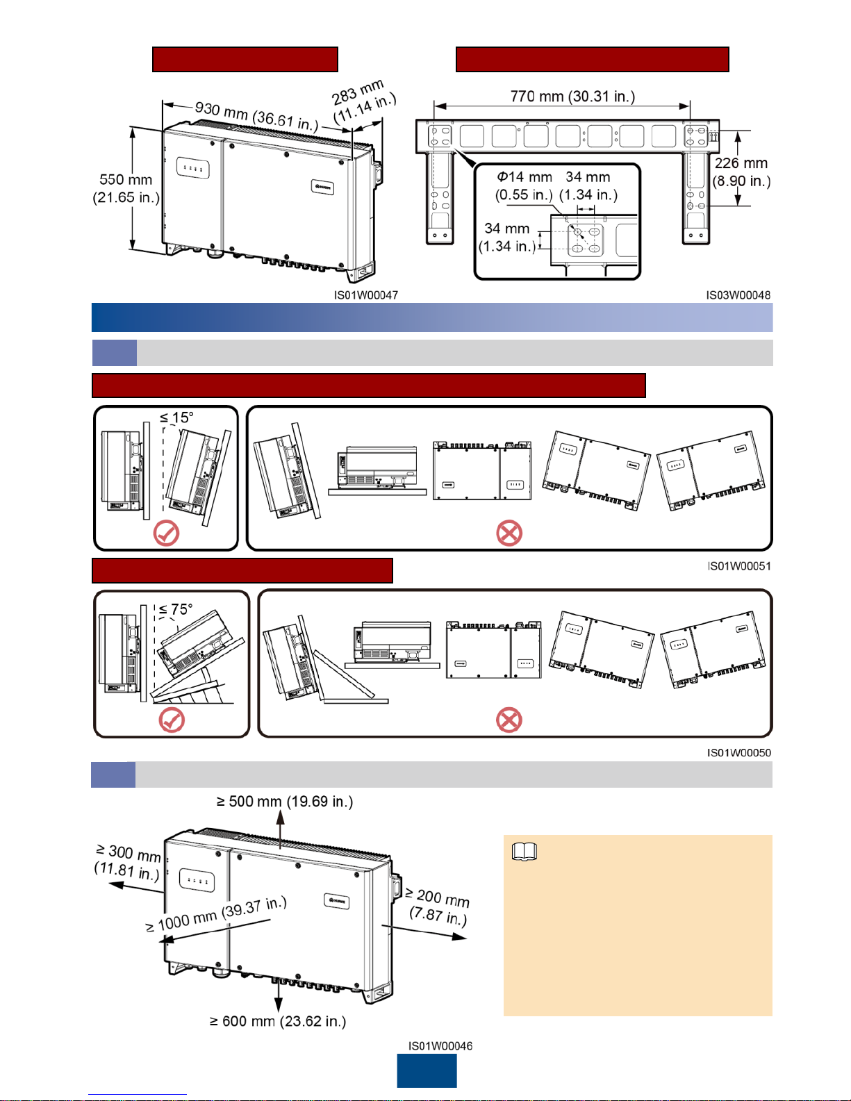
Chassis Dimensions
2
Mounting Bracket Dimensions
2
Installation Requirements
Installation Space
2.2
For ease of installing the SUN2000
on the mounting bracket, connecting
cables to the bottom of the
SUN2000, and maintaining the
SUN2000 in future, it is
recommended that the bottom
clearance be between 600 mm
(23.62 in.) and 730 mm (28.74 in.).
Installation Angle
2.1
Wall-mounted Installation and Normal Support-mounted Installation
Tilted Support-mounted Installation
NOTE
Page 4
3
3
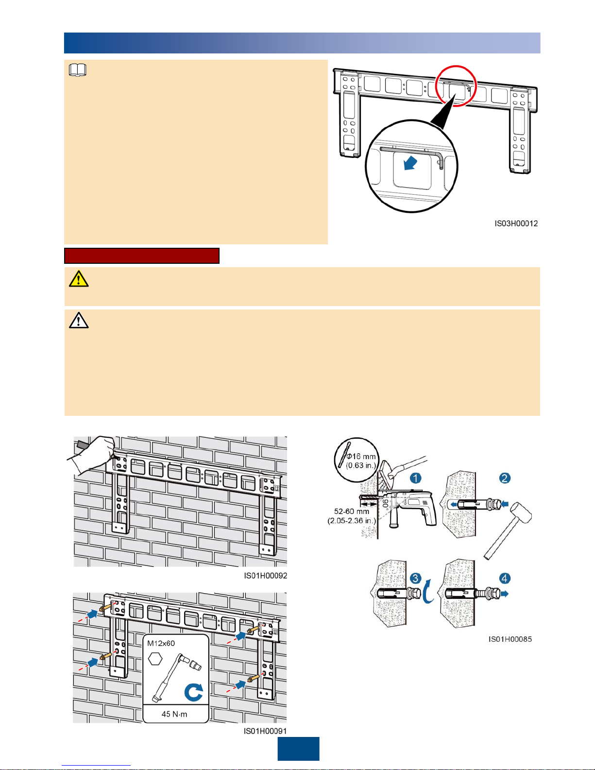
Installing the Mounting Bracket
2. Install expansion bolts.
The SUN2000 mounting bracket has four groups
of tapped holes, each group containing four
tapped holes. Mark any hole in each group based
on site requirements and mark four holes in total.
Two round holes are preferred.
The SUN2000 is delivered with M12x60
expansion bolts and M12x40 bolt assemblies. If
the bolt assembly length does not meet the
installation requirements, prepare M12 bolt
assemblies by yourself and use them together
with the delivered M12 nuts.
Before installing the mounting bracket, remove
the security torx wrench from the mounting
bracket and set it aside.
3. Secure the mounting bracket.
Wall-mounted Installation
1. Mark hole positions.
To prevent dust inhalation or contact with eyes, wear safety goggles and an anti-dust mask
when drilling holes.
Wipe away any dust in or around the holes and measure the hole distance. If the holes are
inaccurately positioned, drill holes again.
Level the head of the expansion sleeve with the concrete wall after removing the bolt, spring
washer, and flat washer. Otherwise, the mounting bracket will not be securely installed on
the concrete wall.
Avoid drilling holes in the water pipes and power cables buried in the wall.
NOTE
NOTICE
DANGER
Page 5
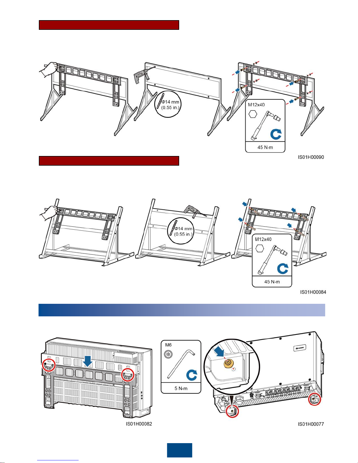
Normal Support-mounted Installation
3. Secure the mounting bracket.1. Mark hole positions.
Tilted Support-mounted Installation
2. Drill holes. (You are advised to
apply anti-rust paint on the
hole positions for protection.)
3. Secure the mounting bracket.1. Mark hole positions. 2. Drill holes. (You are advised to
apply anti-rust paint on the
hole positions for protection.)
4
4
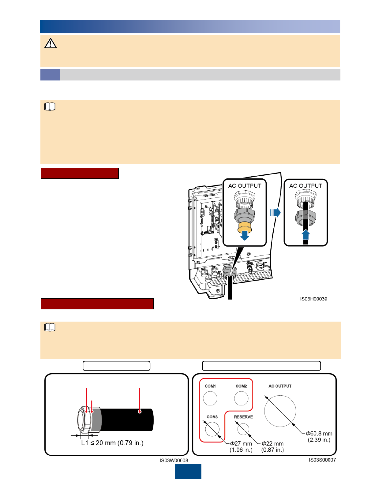
Installing the SUN2000
1. Install the SUN2000 on the mounting bracket. 2. Tighten security torx screws.
Page 6
5
5
Electrical Connections
Connect cables in accordance with the installation laws and regulations of the country or region
where the project is located.
Selecting a Connection Method
5.1
Cables can be connected to the maintenance compartment in a common way or through a pipe.
Select a connection method based on site requirements.
The following describes how to route cables through the AC OUTPUT waterproof connector in a
common way and through a pipe. Processing of other waterproof connectors is similar.
Following are the reference torque values for the waterproof connector and pipe. Observe the
requirements of the specific manufacturer, if any.
− AC OUTPUT and COM ports: 7.5 N·m (plastic) or 10 N·m (metal)
− RESERVE port: 3.75 N·m (plastic) or 6.25 N·m (metal)
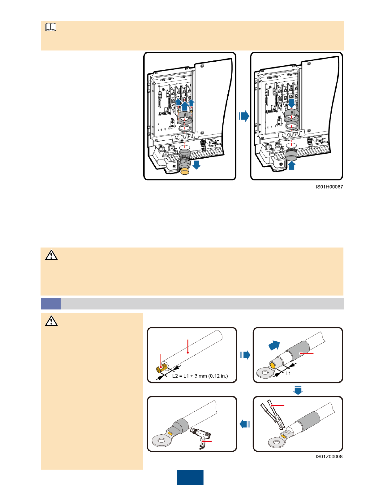
Common Connection
1. Remove the locking cap and plug from
the waterproof connector.
2. Route the cable through the locking cap
and then the waterproof connector.
3. Install the cable.
4. Tighten the locking cap.
5. Check that the cables are connected
correctly and securely. Then seal the
waterproof connectors and cable holes.
6. Clear foreign matter from the
maintenance compartment.
If you choose the common connection,
prepare appropriate cables by yourself.
Connection Through a Pipe
If you choose the connection through pipes, prepare appropriate cables and pipes by yourself.
The pipe specifications should comply with the waterproof connector specifications. For example,
for a 2-inch waterproof connector, prepare a 2-inch pipe. The pipe appearance shown in the
following figure is for reference only. The actual pipe prevails.
Diameters of the bottom cable holes
Fitting
Conduit
Pipe
Nut
NOTICE
NOTE
NOTE
Page 7
6
1. Remove the AC filter and
keep the screws aside.
2. Remove the locking cap
and plug from the
waterproof connector, and
then remove the
waterproof connector.
3. Secure the pipe fittings.
4. Place the AC filter.
AC filter operation is required only for the AC OUTPUT waterproof connector, not required for other
waterproof connectors.
5. Route the cable through the conduit and fitting of the pipe, and then the AC filter.
6. Install the cable.
7. Connect the conduit and fitting of the pipe.
8. Check that the cables are connected correctly and securely. Then take appropriate measures to
ensure that the tube conduit and fittings are secured reliably, and seal the cable holes.
9. Secure the AC filter using screws.
10.Clear foreign matter from the maintenance compartment.
How to handle the bottom waterproof connectors depends on the connection method. For
details, see "Common Connection" and "Connection Through a Pipe."
Cables to the maintenance compartment interior are connected in the same way irrespective of
which connection method is used. The following uses common connection as an example.
Core wire
Insulation layer
Heat
shrink
tubing
Hydraulic
pliers
Heat
gun
Preparing an OT Terminal
5.2
Pay attention to not scratch
the core wire when stripping
a cable.
The cavity formed after the
conductor crimp strip of the
OT terminal is crimped must
wrap the core wires
completely. The core wires
must contact the OT
terminal closely.
Wrap the wire crimping area
with heat shrink tubing or
PVC insulation tape. The
following figure uses heat
shrink tubing as an example.
When using the heat gun,
protect devices from being
scorched.
NOTICE
NOTE
NOTICE
Page 8
7
Installing the Ground Cable
5.3
Proper grounding is helpful for resisting the impact of surge voltage and improving the
electromagnetic interference (EMI) performance. Before connecting the AC power cable, DC power
cable, and communications cable, connect ground cables to the PE point and PV side ground point.
Both the maintenance compartment and shell of the SUN2000 provide a PE point. Select either
for connecting the ground cable. If you connect a ground cable to the PE point in the
maintenance compartment, see section 5.5 "Installing AC Output Power Cables."
You are advised to use outdoor copper-core cables with a cross-sectional area of 6 AWG and
M6 OT terminals. The ground cable must be secured.
It is recommended that the ground cable be connected to a nearby ground point. Connect the
ground points of all SUN2000s in the same PV array to ensure equipotential connections to
ground cables.
To enhance the corrosion resistance of the ground terminal, apply silica gel or paint on it after
connecting the ground cable.
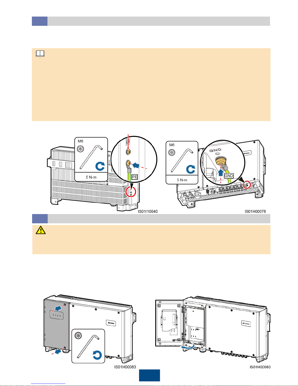
1. Connect the ground cable to the PE point
(on the chassis shell).
2. Connect the ground cable to the PV side
ground point.
Opening the Maintenance Compartment Door
5.4
Never open the host panel of the SUN2000.
Before opening the SUN2000 maintenance compartment door, turn off the downstream AC
output switch and the two bottom DC switches.
Reserved PE point
1. Remove the two security torx screws from the
maintenance compartment door using a security
torx wrench. (Set the two screws aside. Use the
idle ground screw on the chassis shell as the
standby screw, and the idle floating nut on the
chassis as the standby floating nut.)
2. Open the maintenance compartment
door and install the support bar.
WARNING
NOTE
Page 9
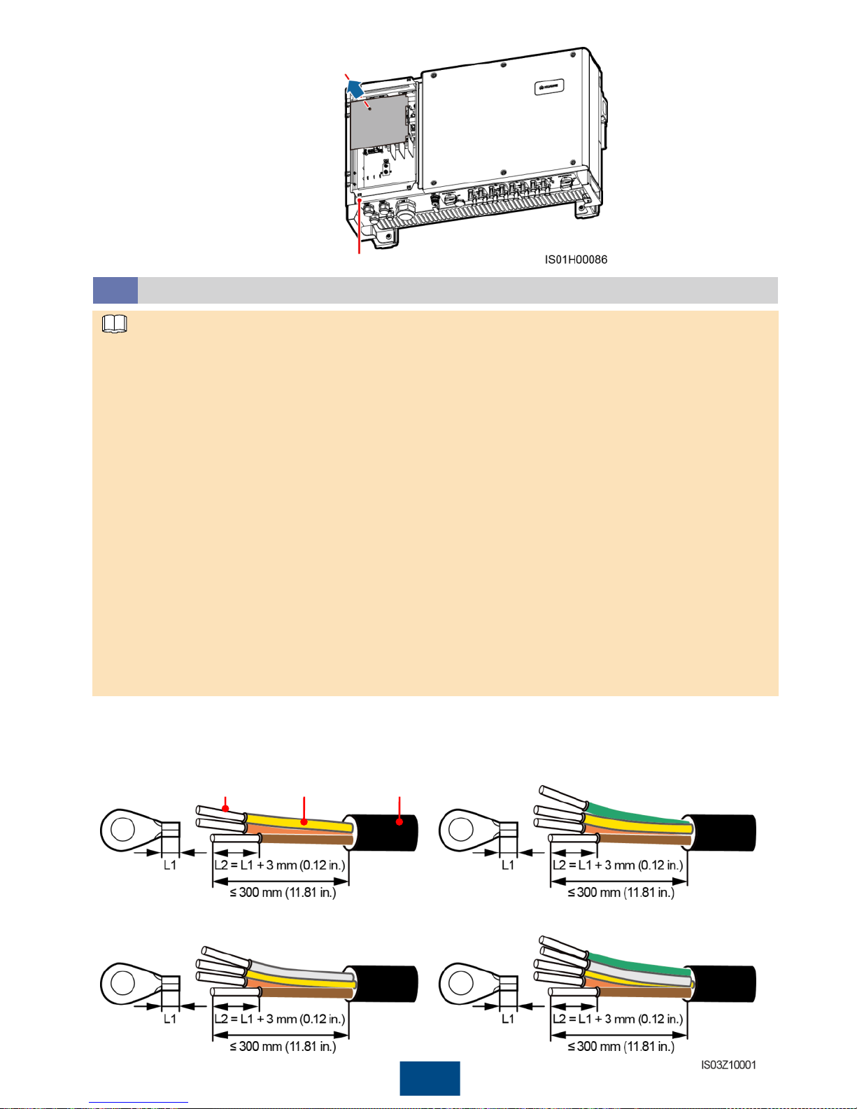
8
3. Remove the AC terminal cover.
Installing AC Output Power Cables
5.5
Recommended: a copper cable that can withstand 90°C (194°F) or 105°C (221°F) and has a
cross-sectional area of 4 AWG for each core wire.
If you connect a ground cable to the PE point on the chassis shell in the scenario with no
neutral wire, you are advised to use a three-core (L1, L2, and L3) outdoor copper cable
(common connection) or three (L1, L2, and L3) single-core outdoor copper cables (connected
through a pipe).
If you connect a ground cable to the PE point in the maintenance compartment in the scenario
with no neutral wire, you are advised to use a four-core (L1, L2, L3, and PE) outdoor copper
cable (common connection) or four (L1, L2, L3, and PE) single-core outdoor copper cables
(connected through a pipe).
If you connect a ground cable to the PE point on the chassis shell in the scenario with a neutral wire,
you are advised to use a four-core (L1, L2, L3, and N) outdoor copper cable (common connection) or
four (L1, L2, L3, and N) single-core outdoor copper cables (connected through a pipe).
If you connect a ground cable to the PE point in the maintenance compartment in the scenario
with a neutral wire, you are advised to use a five-core (L1, L2, L3, N, and PE) outdoor copper
cable (common connection) or five (L1, L2, L3, N, and PE) single-core outdoor copper cables
(connected through a pipe).
OT terminal: M8 (L1, L2, L3, and N) and M6 (PE)
Copper-core cables with copper wiring terminals are recommended. For the requirements on
the cables and terminals made of other materials as well as more detailed cable specifications,
see the SUN2000-(33KTL, 36KTL, 40KTL)-US User Manual.
1. Remove an appropriate length of the jacket and insulation layer from the AC output power cable
using a wire stripper. (Ensure that the jacket is in the maintenance compartment.)
a. Three-core cable (excluding the ground
cable and neutral wire)
c. Four-core cable (excluding the ground
cable but including the neutral wire)
JacketInsulation layerCore wire
b. Four-core cable (including the ground cable
but excluding the neutral wire)
d. Five-core cable (including the ground cable
and neutral wire)
Position of the standby floating nut
NOTE
Page 10
9
Ensure that the AC output power cable is connected securely. Otherwise, the SUN2000 may fail to
operate or experience any fault that will cause the damage of the terminal block. For example, the
SUN2000 may generate heat during operation due to unreliable connection.
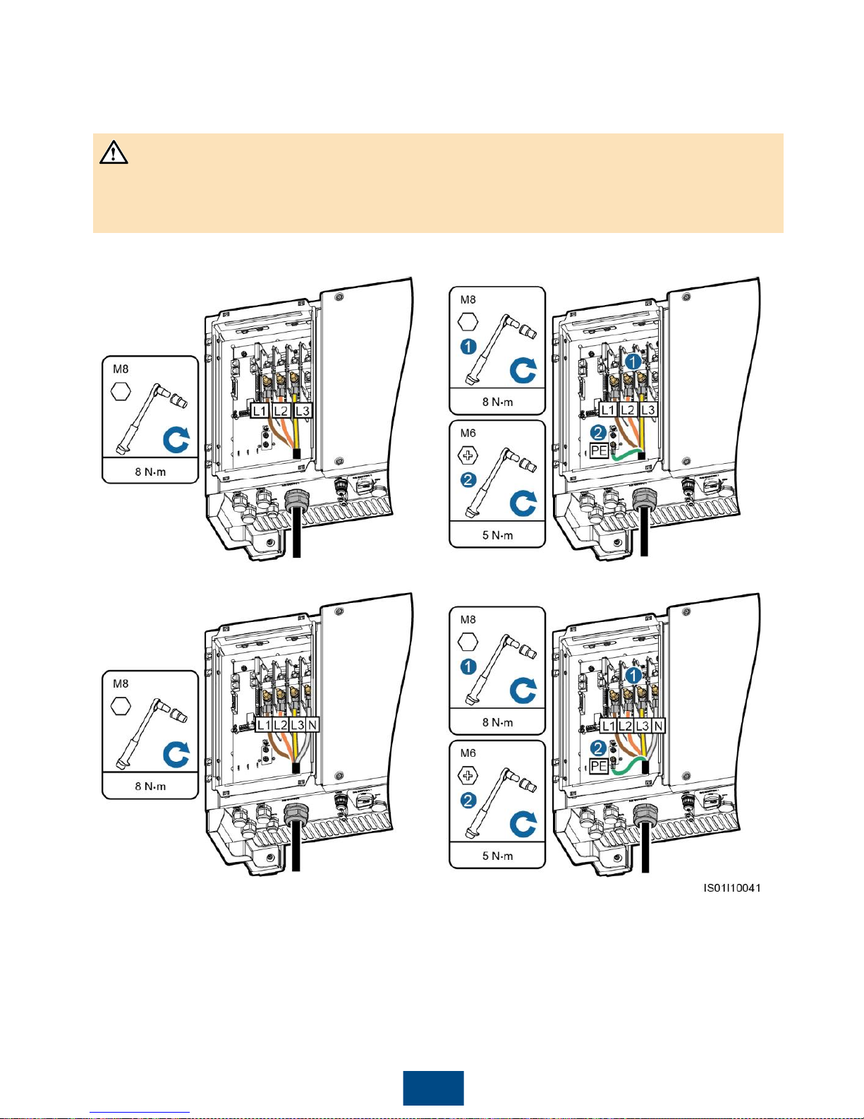
2. Prepare OT terminals.
3. Route the AC output power cable into the maintenance compartment.
4. Connect the AC output power cables and secure them using a socket wrench with an
extension rod.
a. Three-core cable (excluding the
ground cable and neutral wire)
c. Four-core cable (excluding the ground
cable but including the neutral wire)
b. Four-core cable (including the ground
cable but excluding the neutral wire)
d. Five-core cable (including the ground
cable and neutral wire)
NOTICE
Page 11
Negative metal terminal (male)
Positive metal terminal (female)
10
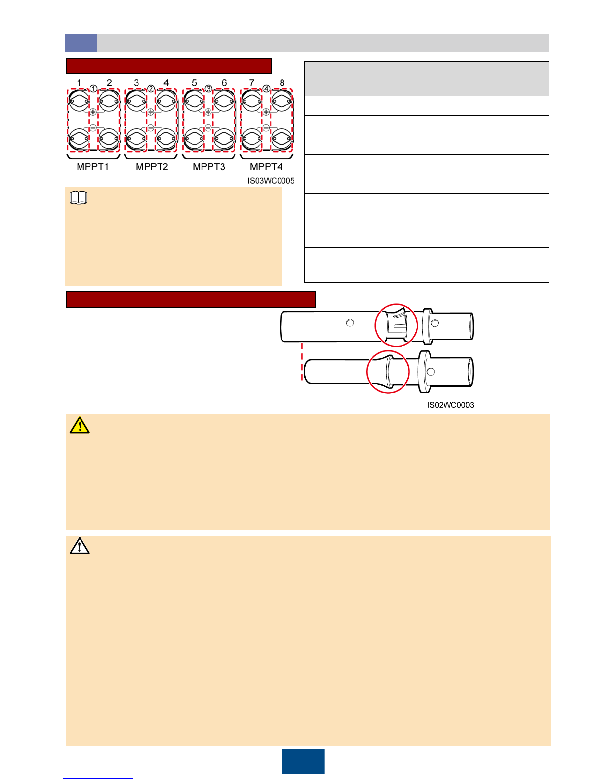
Installing DC Input Power Cables
5.6
Selecting DC Input Terminals
The SUN2000 provides two DC switches,
namely, DC SWITCH 1 and DC SWITCH
2. DC SWITCH 1 controls the first to
fourth routes of DC input terminals,
whereas DC SWITCH 2 controls the fifth
to eighth routes of DC input terminals.
Number
of Inputs
SUN2000
1
Connects to any route.
2
Connects to routes 1 and 5.
3
Connects to routes 1, 3, and 5.
4
Connects to routes 1, 3, 5, and 7.
5
Connects to routes 1, 2, 3, 5, and 7.
6
Connects to routes 1, 2, 3, 5, 6, and 7.
7
Connects to routes 1, 2, 3, 4, 5, 6,
and 7.
8
Connects to routes 1, 2, 3, 4, 5, 6, 7,
and 8.
Positive and Negative Metal Terminals
1. Use the positive and negative metal terminals and DC connectors supplied with the SUN2000. Using
other models of positive and negative metal terminals and DC connectors may result in serious
consequences. The caused device damage is not covered under any warranty or service agreement.
2. Before connecting DC input power cables, label the cable polarities to ensure correct cable
connections. If the cables are connected incorrectly, the SUN2000 may be damaged.
3. Insert the crimped metal terminals of the positive and negative power cables into the appropriate
positive and negative connectors. Then pull back the DC input power cables to ensure that they
are connected securely.
4. Connect the positive and negative connectors to the appropriate positive and negative DC input
terminals. Then pull back the DC input power cables to ensure that they are connected securely.
5. If the DC input power cable is reversely connected, do not operate the DC switches and positive
and negative connectors immediately. Otherwise, the SUN2000 will be damaged. The caused
equipment damage is beyond the warranty scope. Wait until the solar irradiance declines at night
and the PV string current reduces to below 0.5 A. Then, turn off the two DC switches, remove the
positive and negative connectors, and correct the polarity of the DC input power cable.
Ensure that the PV module output is well insulated to ground.
Before inserting the positive and negative connectors respectively into the positive and negative
DC input terminals of the SUN2000, check that the DC voltage does not exceed 1000 V using a
multimeter and that the cables are connected correctly. Otherwise, the SUN2000 will be damaged.
− If the voltage is a negative value, the PV string is reversely connected. Correct the polarity.
− If the voltage is greater than 1000 V DC, too many PV modules are configured. Remove some
PV modules.
NOTE
WARNING
NOTICE
Page 12
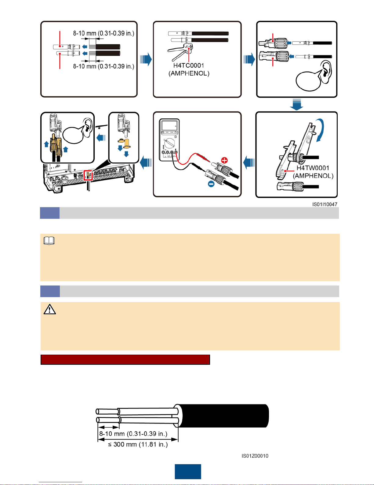
11
Positive connector
Negative
connector
Positive metal terminal
Negative metal terminal
Recommended: 12 AWG PV
cable (PV1-F)
Ensure that the cable cannot
be removed after crimped.
Click
Ensure that
the locking nut
is secured.
Ensure that the
cables are correctly
connected and that
the voltage does not
exceed 1000 V DC.
Click
1. If PLC is used, you do not have to connect any communications cable to the SUN2000, but
have to connect the PLC CCO module or SmartLogger2000 to the AC power cable. For detailed
operations, see the PLC CCO01A User Manual or SmartLogger2000 User Manual.
2. If RS485 is used, do not connect the PLC CCO module to the AC power cable.
Installing the RS485 Communications Cable
5.8
1. When routing communications cables, separate communications cables from power cables to
prevent communication from being affected by signal interference.
2. An RS485 cable can connect to either a terminal block or an RJ45 network port. It is
recommended that the RS485 cable connect to a terminal block.
Selecting a Communication Mode
5.7
The SUN2000 supports either PLC or RS485 communication mode.
Terminal Block Connection (Recommended)
Recommended: outdoor communications cable with a conductor cross-sectional area of 18 AWG
and an outer diameter range of 14 mm to 18 mm (0.55 in. to 0.71 in.)
1. Remove an appropriate length of the jacket and core wire insulation layer from the
communications cable using a wire stripper.
NOTICE
NOTE
Page 13
12
2. Route the communications cables into the maintenance compartment.
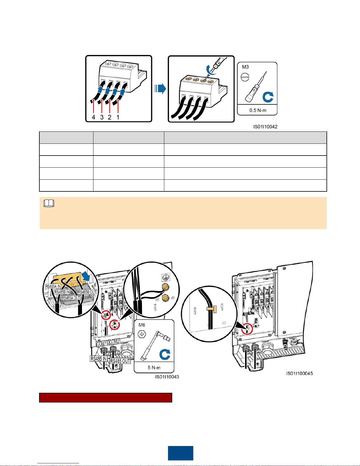
3. Remove the cable terminal base from the terminal block. Connect the communications cables to
the terminal base.
No.
Port Definition
Description
1
RS485A IN
RS485A, RS485 differential signal +
2
RS485A OUT
RS485A, RS485 differential signal +
3
RS485B IN
RS485B, RS485 differential signal
–
4
RS485B OUT
RS485B, RS485 differential signal
–
4. Install the terminal base on the terminal
block, and connect the shield layer to the
ground point.
5. Bind the communications cables.
When connecting the shielded cables, choose whether to crimp the OT terminal based on site
requirements.
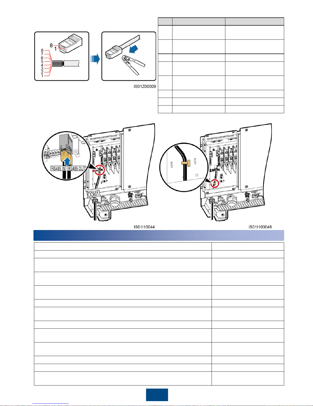
RJ45 Network Port Connection
You are advised to use a CAT 5E outdoor shielded network cable with an outer diameter less than
9 mm (0.35 in.) and internal resistance not greater than 1.5 ohms/10 m (1.5 ohms/393.70 in.), as
well as a shielded RJ45 connector.
NOTE
Page 14
13
No.
Color
Pin Definition
1
White
-and-orange
RS485A, RS485
differential signal +
2
Orange
RS485B, RS485
differential signal
–
3
White
-and-green
N/A
4
Blue
RS485A, RS485
differential signal +
5
White
-and-blue
RS485B, RS485
differential signal
–
6
Green
N/A
7
White
-and-brown
N/A
8
Brown
N/A
1. Prepare an RJ45 connector.
2. Route the communications cables
into the maintenance compartment.
3. Insert the RJ45 connectors into the RJ45
network ports in the SUN2000
maintenance compartment.
4. Bind the communications cables.
6
Checking After Installation
1.
The SUN2000 is installed correctly and securely.
Yes
□No□
N/A
□
2.
The DC switches and downstream AC switch are OFF.
Yes
□No□
N/A
□
3.
Ground cables are connected correctly and securely, without open
circuits or short circuits.
Yes
□No□
N/A
□
4.
AC output power cables are connected correctly and securely,
without open circuits or short circuits.
Yes
□No□
N/A
□
5.
DC input power cables are connected correctly and securely,
without open circuits or short circuits.
Yes
□No□
N/A
□
6.
The communications cables are connected correctly and securely.
Yes
□No□
N/A
□
7. All pipes and the waterproof connectors in use at the chassis bottom
are sealed.
Yes
□No□
N/A
□
8.
The AC terminal cover is reinstalled.
Yes
□No□
N/A
□
9.
Check that the maintenance compartment is clean and tidy, without
foreign matter.
Yes
□No□
N/A
□
10.
The maintenance compartment door is closed and the door screws
are tightened.
Yes
□No□
N/A
□
11.
Idle DC input terminals are sealed.
Yes
□No□
N/A
□
12.
Idle USB ports are plugged with covers.
Yes
□No□
N/A
□
13.
Idle RESERVE and COM waterproof connectors are plugged and
the locking caps are tightened.
Yes
□No□
N/A
□
Page 15
14
7
Powering On the System
1. Turn on the AC switch between the SUN2000 and the power grid.
2. Ensure that the DC switches at the chassis bottom are ON.
3. (Optional) Measure the temperatures at the joints between DC terminals and connectors using a
point-test thermometer.
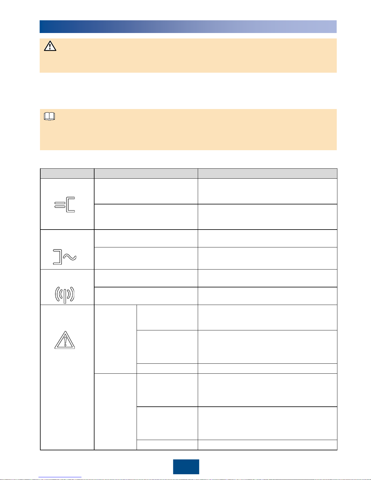
4. Observe the indicators to check the SUN2000 operating status.
Before turning on the AC switch between the SUN2000 and the power grid, use a multimeter to
check that the AC voltage is within the operating voltage range of the SUN2000.
To ensure that the DC terminals are in good contact, check the temperatures at the joints between
DC terminals and connectors after the SUN2000 has been running for a period of time. Ensure that
the temperature rise does not exceed 40°C (104°F).
Indicator
Status
Description
PV connection
indicator
Steady green
At least one PV string is properly connected,
and the DC input voltage of the corresponding
MPPT circuit is higher than or equal to 200 V.
Off
The SUN2000 disconnects from all PV strings,
or the DC input voltage of each MPPT circuit is
less than 200 V.
Grid
-tied
indicator
Steady green
The SUN2000 has connected to the power
grid.
Off
The SUN2000 does not connect to the
power grid.
Communications
indicator
Blinking green (on for 0.5s and
then off for 0.5s)
The SUN2000 receives data over RS485/PLC
communication.
Off
The SUN2000 has not received data over
RS485/PLC communication for 10 seconds.
Alarm/
Maintenance
indicator
Alarm status
Blinking red at long
intervals (on for 1s
and then off for 4s)
A warning alarm is generated.
Blinking red at
short intervals (on
for 0.5s and then
off for 0.5s)
A minor alarm is generated.
Steady red
A major alarm is generated.
Local
maintenance
status
Blinking green at
long intervals (on
for 1s and then off
for 1s)
Local maintenance is in progress.
Blinking green at
short intervals (on
for 0.125s and then
off for 0.125s)
Local maintenance fails.
Steady green
Local maintenance succeeds.
NOTICE
NOTE
Page 16
15
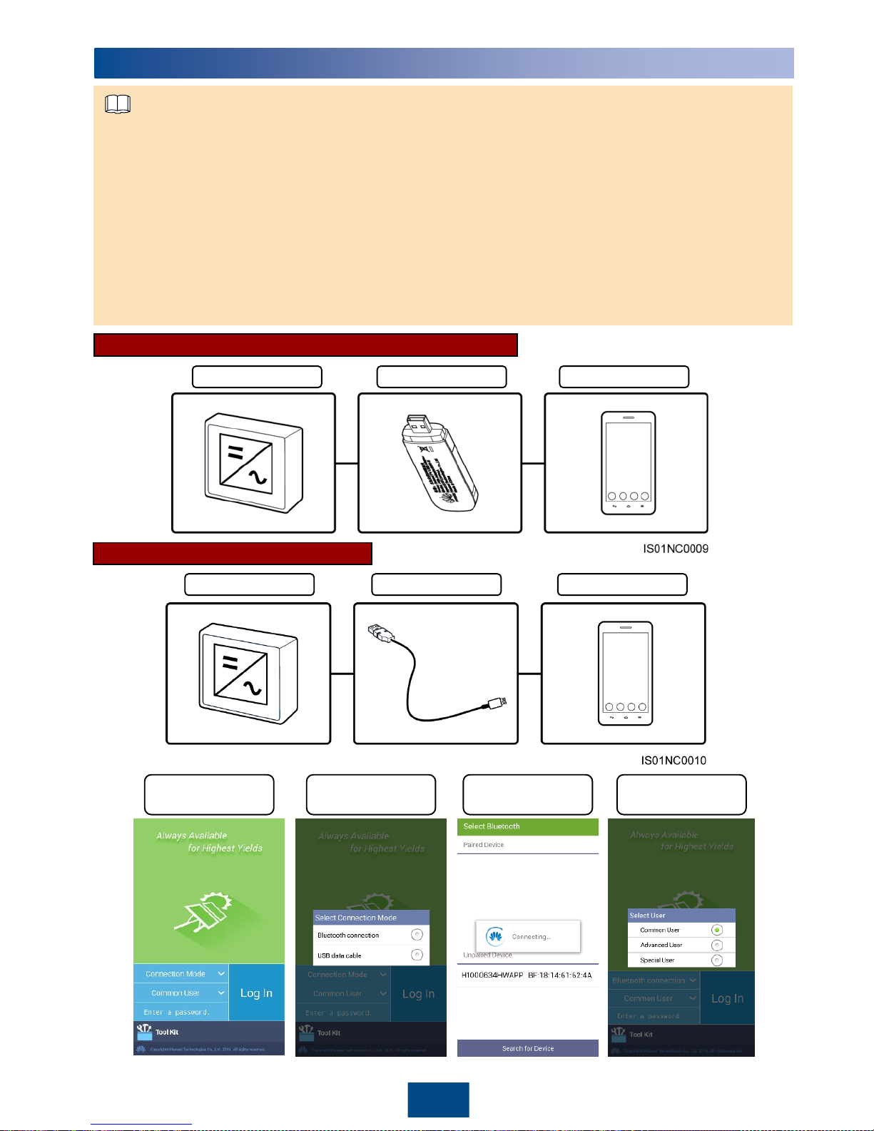
1. The SUN2000 app enables the SUN2000 to communicate with the monitoring system through a
USB data cable or Bluetooth for you to query alarms, configure parameters, and perform routine
maintenance. The SUN2000 app is a convenient platform for local monitoring and maintenance.
The app name is SUN2000.
2. Mobile phone operating system: Android 4.0 or later, iOS 7.0 or later. When the iOS is used, the
app supports only Bluetooth connection.
3. Access the Huawei app store (http://appstore.huawei.com), Google Play
(https://play.google.com), or App Store (iOS), search for SUN2000, and download the SUN2000
app software package.
4. Connect a USB data cable or a Bluetooth module to the USB port of the SUN2000 to implement
the communication between the SUN2000 and the app.
SUN2000 App
8
SUN2000 Bluetooth module Mobile phone
Login screen
Selecting a
connection mode
Connecting
Bluetooth
Switching
between users
SUN2000 USB data cable Mobile phone
Bluetooth Module Connection (Android and iOS)
Data Cable Connection (Android)
NOTE
Page 17
16
Tap to return to the login screen.
By default, the SUN2000 can be grid-tied and you
do not have to set parameters. You can modify
the parameters based on site requirements. For
details about parameter configuration, see the
SUN2000 APP User Manual.
The preset passwords for Common User,
Advanced User, and Special User of the
SUN2000 app are 00000a.
Use the preset password upon initial login. To
ensure account security, change the password
immediately after login.
The screenshots in this document correspond to
app 2.1.20.101 (Android).
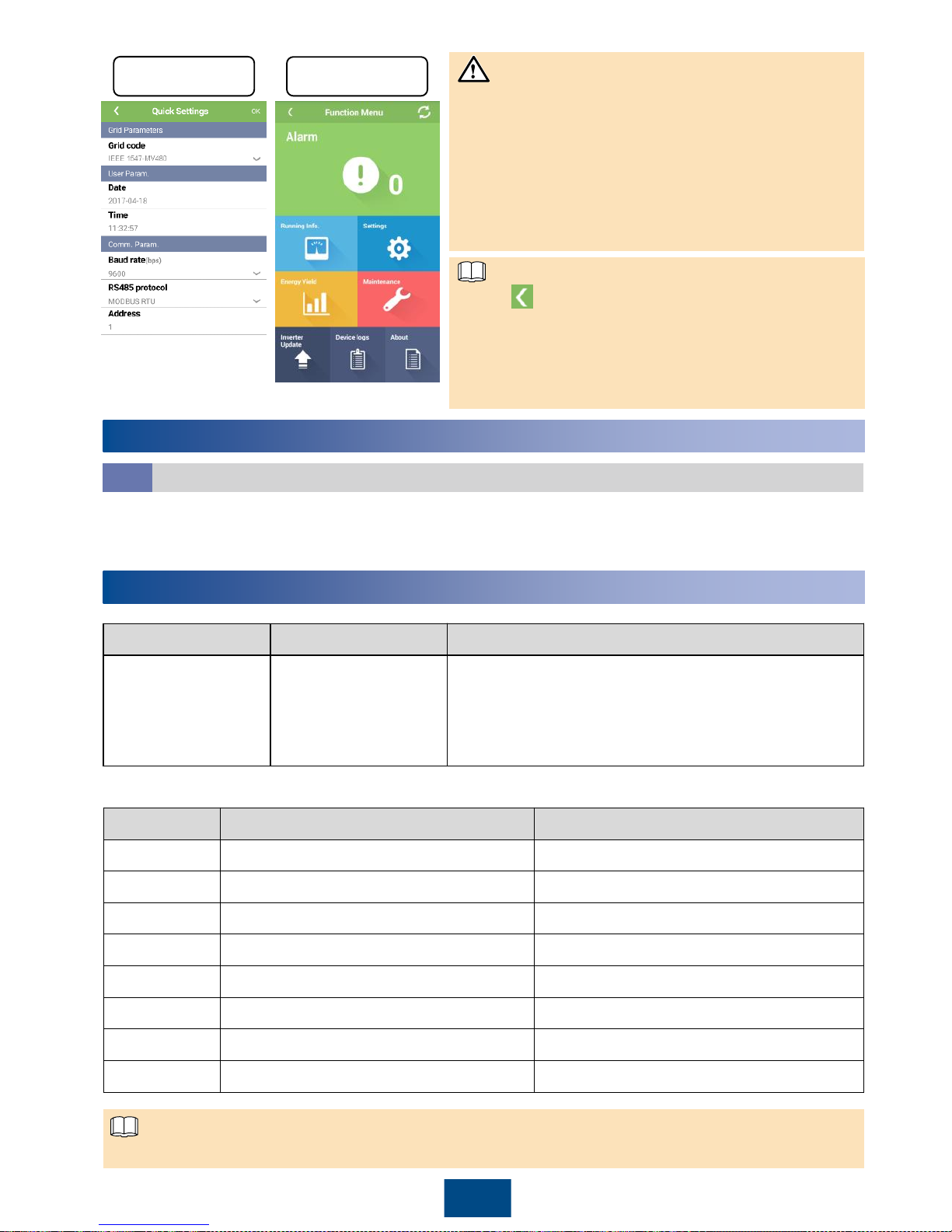
Quick settings
Function Menu
How Should I View Active Alarms?
Connect a USB data cable or a Bluetooth module to the USB port of the SUN2000 to implement
the communication between the SUN2000 and the app. After login, tap Alarm on the Function
Menu screen to display the Active Alarm screen.
Symptom
Possible Cause
Suggestion
The PV string is
connected reversely.
The PV string cables
are connected
reversely during the
SUN2000 installation.
Wait until the solar irradiance declines at night and the
PV string current reduces to below 0.5 A. Then, turn
off the two DC switches, remove the positive and
negative connectors, and
correct the polarity
of the DC
input power cable.
Appendix: Power Grid Codes
No.
Power Grid Code
Country and Condition
1
IEEE 1547
-MV480
US medium
-voltage power grid
2
IEEE 1547a
-MV480
2016 US medium
-voltage power grid
3
PRC_024_ERCOT
-MV480
Texas medium
-voltage power grid
4
PRC_024_Eastern
-MV480
Eastern US medium
-voltage power grid
5
PRC_024_Western
-MV480
Western US medium
-voltage power grid
6
PRC_024_Quebec
-MV480
Quebec medium
-voltage power grid
7
ELECTRIC RULE NO.21
-MV480
California medium
-voltage power grid
8
HECO
-MV480
Hawaii medium
-voltage power grid
Grid codes are subject to change. The listed codes are for your reference only.
10
Troubleshooting
9
FAQ
NOTICE
NOTE
NOTE
Page 18
Scan here for more documents:
Scan here for technical support (carrier):
Huawei Technologies Co., Ltd.
Huawei Industrial Base, Bantian, Longgang
Shenzhen 518129 People's Republic of China
www.huawei.com
You can also log in to Huawei technical support website:
http://support.huawei.com
Google Play Huawei App Store
Apple Store
Support WeChat
 Loading...