


SUN2000-(100KTL, 110KTL, 125KTL) Series
User Manual
Issue
Preliminary Version 3.0
Date
2019-12-08
HUAWEI TECHNOLOGIES CO., LTD.

Issue Preliminary Version 3.0
(2019-12-08)
Copyright © Huawei Technologies Co., Ltd.
i
Copyright © Huawei Technologies Co., Ltd. 2019. All rights reserved.
No part of this document may be reproduced or transmitted in any form or by any means without prior
written consent of Huawei Technologies Co., Ltd.
Trademarks and Permissions
and other Huawei trademarks are trademarks of Huawei Technologies Co., Ltd.
All other trademarks and trade names mentioned in this document are the property of their respective
holders.
Notice
The purchased products, services and features are stipulated by the contract made between Huawei and
the customer. All or part of the products, services and features described in this document may not be
within the purchase scope or the usage scope. Unless otherwise specified in the contract, all statements,
information, and recommendations in this document are provided "AS IS" without warranties, guarantees or
representations of any kind, either express or implied.
The information in this document is subject to change without notice. Every effort has been made in the
preparation of this document to ensure accuracy of the contents, but all statements, information, and
recommendations in this document do not constitute a warranty of any kind, express or implied.
Huawei Technologies Co., Ltd.
Address:
Huawei Industrial Base
Bantian, Longgang
Shenzhen 518129
People's Republic of China
Website:
https://e.huawei.com
SUN2000-(100KTL, 110KTL, 125KTL) Series
User Manual
About This Document
Issue Preliminary Version 3.0
(2019-12-08)
Copyright © Huawei Technologies Co., Ltd.
ii
Overview
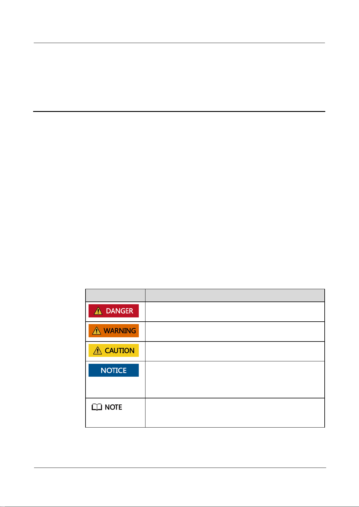
Symbol
Description
Indicates a hazard with a high level of risk which, if not avoided,
will result in death or serious injury.
Indicates a hazard with a medium level of risk which, if not
avoided, could result in death or serious injury.
Indicates a hazard with a low level of risk which, if not avoided,
could result in minor or moderate injury.
Indicates a potentially hazardous situation which, if not avoided,
could result in equipment damage, data loss, performance
deterioration, or unanticipated results.
NOTICE is used to address practices not related to personal injury.
Supplements the important information in the main text.
NOTE is used to address information not related to personal injury,
equipment damage, and environment deterioration.
This document describes the SUN2000-125KTL-M0, SUN2000-110KTL-M0,
SUN2000-100KTL-M0, SUN2000-100KTL-M1 and SUN2000-100KTL-INM0 (SUN2000
for short) in terms of installation, electrical connection, commissioning, maintenance, and
troubleshooting. Before installing and operating the solar inverter, ensure that you are familiar
with the features, functions, and safety precautions provided in this document.
Intended Audience
About This Document
This document is intended for photovoltaic (PV) plant operating personnel and qualified
electricians.
Symbol Conventions
The symbols that may be found in this document are defined as follows.

SUN2000-(100KTL, 110KTL, 125KTL) Series
User Manual
About This Document
Issue Preliminary Version 3.0
(2019-12-08)
Copyright © Huawei Technologies Co., Ltd.
iii
Change History
Changes between document issues are cumulative. The latest document issue contains all the
changes made in earlier issues.
Issue Preliminary Version 03 (2019-12-08)
Updated 3 Solar Inverter Storage.
Updated 4.5 Installing a Solar Inverter.
Updated 5.2 Preparing Cables.
Updated 5.6 Connecting an AC Output Power Cable.
Updated 5.7 Connecting DC Input Power Cables.
Updated 5.8 Connecting the RS485 Communications Cable.
Updated 7.1.1 App Introduction.
Updated 8.2 Power-Off for Troubleshooting.
Added 8.2 Power-Off for Troubleshooting.
Updated 10 Technical Specifications.
Added A Securing Y-Branch Connectors.
Updated B Grid Code.
Added C Domain Name List of Management Systems.
Issue 02 (2019-08-09)
Added the SUN2000-110KTL-M0, SUN2000-100KTL-M0, SUN2000-100KTL-M1, and
SUN2000-100KTL-INM0 models.
Issue 01 (2019-05-15)
This issue is used for first office application (FOA).

SUN2000-(100KTL, 110KTL, 125KTL) Series
User Manual
Contents
Issue Preliminary Version 3.0
(2019-12-08)
Copyright © Huawei Technologies Co., Ltd.
iv
Contents
About This Document .................................................................................................................... ii
1 Safety Information ........................................................................................................................ 1
1.1 General Safety .............................................................................................................................................................. 1
1.2 Personnel Requirements ............................................................................................................................................... 2
1.3 Electrical Safety ............................................................................................................................................................ 3
1.4 Installation Environment Requirements ....................................................................................................................... 4
1.5 Mechanical Safety ........................................................................................................................................................ 4
1.6 Commissioning ............................................................................................................................................................. 5
1.7 Maintenance and Replacement ..................................................................................................................................... 5
2 Overview ......................................................................................................................................... 7
2.1 Product Model .............................................................................................................................................................. 7
2.2 Overview ...................................................................................................................................................................... 9
2.3 Label Description ........................................................................................................................................................ 11
2.4 Product Appearance .................................................................................................................................................... 13
2.4.1 Product Appearance ................................................................................................................................................. 13
2.4.2 Indicator Status ........................................................................................................................................................ 15
2.5 Working Principles...................................................................................................................................................... 17
2.5.1 Circuit Diagram ....................................................................................................................................................... 17
2.5.2 Working Modes ........................................................................................................................................................ 19
3 Solar Inverter Storage ................................................................................................................. 22
4 Installation.................................................................................................................................... 24
4.1 Check Before Installation ........................................................................................................................................... 24
4.2 Tools ........................................................................................................................................................................... 24
4.3 Determining the Installation Position ......................................................................................................................... 26
4.4 Installing the Mounting Bracket ................................................................................................................................. 30
4.4.1 Support-mounted Installation .................................................................................................................................. 31
4.4.2 Wall-mounted Installation ........................................................................................................................................ 32
4.5 Installing a Solar Inverter ........................................................................................................................................... 33
5 Electrical Connections ................................................................................................................ 38
5.1 Precautions .................................................................................................................................................................. 38
5.2 Preparing Cables ......................................................................................................................................................... 38

SUN2000-(100KTL, 110KTL, 125KTL) Series
User Manual
Contents
Issue Preliminary Version 3.0
(2019-12-08)
Copyright © Huawei Technologies Co., Ltd.
v
5.3 Connecting the PE Cable ............................................................................................................................................ 47
5.4 Opening the Maintenance Compartment Door ........................................................................................................... 48
5.5 (Optional) Installing the Power Cable of the Tracking System .................................................................................. 51
5.6 Connecting an AC Output Power Cable ..................................................................................................................... 52
5.7 Connecting DC Input Power Cables ........................................................................................................................... 57
5.8 Connecting the RS485 Communications Cable .......................................................................................................... 63
6 Commissioning............................................................................................................................ 65
6.1 Check Before Power-on .............................................................................................................................................. 65
6.2 Powering On the SUN2000 ........................................................................................................................................ 65
7 Man-Machine Interactions ........................................................................................................ 67
7.1 Operations with the SUN2000 App ............................................................................................................................ 67
7.1.1 App Introduction ...................................................................................................................................................... 67
7.1.2 Downloading and Installing the App ....................................................................................................................... 71
7.1.3 App Login ................................................................................................................................................................ 71
7.1.4 Operations Related to the Common User ................................................................................................................ 74
7.1.4.1 Setting User Parameters ........................................................................................................................................ 74
7.1.4.2 Starting and Shutting Down the SUN2000 ........................................................................................................... 75
7.1.5 Operations Related to the Advanced User ............................................................................................................... 75
7.1.5.1 Parameter Settings ................................................................................................................................................ 75
7.1.5.1.1 Setting Grid Parameters ..................................................................................................................................... 75
7.1.5.1.2 Setting Protection Parameters ............................................................................................................................ 76
7.1.5.1.3 Setting Feature Parameters ................................................................................................................................ 76
7.1.5.1.4 Setting User Parameters ..................................................................................................................................... 81
7.1.5.1.5 Setting the Grid-tied Control Parameters ........................................................................................................... 82
7.1.5.1.6 Setting Communications Parameters ................................................................................................................. 84
7.1.5.1.7 Setting the Tracking System .............................................................................................................................. 86
7.1.5.1.8 Setting a File Save Path ..................................................................................................................................... 88
7.1.5.1.9 Configuring a PV Plant ...................................................................................................................................... 88
7.1.5.2 System Maintenance ............................................................................................................................................. 91
7.1.5.2.1 Device inspection ............................................................................................................................................... 91
7.1.5.2.2 Managing the License ........................................................................................................................................ 91
7.1.5.2.3 Device management ........................................................................................................................................... 92
7.1.5.2.4 PV String Access Detection ............................................................................................................................... 93
7.1.5.2.5 Starting and Shutting Down the SUN2000 ........................................................................................................ 95
7.1.5.2.6 Restoring Factory Settings ................................................................................................................................. 95
7.1.5.2.7 Resetting the SUN2000 ..................................................................................................................................... 95
7.1.5.2.8 Resetting Alarms ................................................................................................................................................ 96
7.1.5.2.9 Clearing Historical Energy Yield Data............................................................................................................... 96
7.1.5.2.10 Importing and Exporting Configuration Files .................................................................................................. 96
7.1.5.3 Device upgrade ..................................................................................................................................................... 96
7.1.5.4 Device Logs .......................................................................................................................................................... 98

SUN2000-(100KTL, 110KTL, 125KTL) Series
User Manual
Contents
Issue Preliminary Version 3.0
(2019-12-08)
Copyright © Huawei Technologies Co., Ltd.
vi
7.1.6 Operations Related to the Special User.................................................................................................................... 98
7.1.6.1 Parameter Settings ................................................................................................................................................ 98
7.1.6.1.1 Setting Grid Parameters ..................................................................................................................................... 98
7.1.6.1.2 Setting Protection Parameters .......................................................................................................................... 100
7.1.6.1.3 Setting Feature Parameters .............................................................................................................................. 102
7.1.6.1.4 Setting the Grid-tied Control Parameters ......................................................................................................... 104
7.1.6.1.5 Setting Power Adjustment Parameters ............................................................................................................. 106
7.1.6.1.6 Setting Reactive Power Control ....................................................................................................................... 109
7.1.6.1.7 Setting User Parameters ................................................................................................................................... 109
7.1.6.1.8 Setting a File Save Path ................................................................................................................................... 110
7.1.6.2 System Maintenance ........................................................................................................................................... 110
7.1.6.2.1 Device management ................................................................ ................................................................ ......... 110
7.1.6.2.2 Starting and Shutting Down the SUN2000 ...................................................................................................... 111
7.1.6.2.3 Restoring Factory Settings ............................................................................................................................... 112
7.1.6.3 Device upgrade ................................................................................................................................................... 112
7.1.6.4 Device Logs ........................................................................................................................................................ 114
7.1.7 Querying the Status ................................................................................................................................................ 114
7.1.7.1 Querying Alarm Records .................................................................................................................................... 114
7.1.7.2 Querying SUN2000 Running Information .......................................................................................................... 115
7.1.7.3 Querying Energy Yield Data ............................................................................................................................... 117
7.1.7.4 Viewing System Version Information ................................................................................................................. 117
7.1.8 Tool Kit .................................................................................................................................................................. 118
7.1.8.1 Scanning SN Bar Codes ...................................................................................................................................... 118
7.1.8.2 SUN2000 Maintenance Script ............................................................................................................................ 120
7.1.8.3 File Manager ....................................................................................................................................................... 121
7.1.8.4 Changing the WLAN password .......................................................................................................................... 121
7.1.8.5 About .................................................................................................................................................................. 122
7.2 (Optional) Installing a Smart Dongle ........................................................................................................................ 122
7.3 Operations with a USB Flash Drive.......................................................................................................................... 123
7.3.1 Exporting Configurations ...................................................................................................................................... 123
7.3.2 Importing Configurations ...................................................................................................................................... 125
7.3.3 Exporting Data ....................................................................................................................................................... 126
7.3.4 Upgrading .............................................................................................................................................................. 127
8 Maintenance ............................................................................................................................... 129
8.1 Shutdown and Power-Off ......................................................................................................................................... 129
8.2 Power-Off for Troubleshooting ................................................................................................................................. 129
8.3 Routine Maintenance ................................................................................................ ................................ ................ 131
8.4 Troubleshooting ........................................................................................................................................................ 132
8.5 Replacing a Fan ........................................................................................................................................................ 140
9 Handling the Inverter ............................................................................................................... 145
9.1 Removing the SUN2000 ........................................................................................................................................... 145

SUN2000-(100KTL, 110KTL, 125KTL) Series
User Manual
Contents
Issue Preliminary Version 3.0
(2019-12-08)
Copyright © Huawei Technologies Co., Ltd.
vii
9.2 Packing the SUN2000 ............................................................................................................................................... 145
9.3 Disposing of the SUN2000 ................................................................................................................................ ....... 145
10 Technical Specifications ........................................................................................................ 146
A Securing Y-Branch Connectors .............................................................................................. 151
B Grid Code ................................................................................................................................... 154
C Domain Name List of Management Systems ..................................................................... 160
D DRM Configuration Guide for Standard As NZS4777.2 ................................................. 161

SUN2000-(100KTL, 110KTL, 125KTL) Series
User Manual
1 Safety Information
Issue Preliminary Version 3.0
(2019-12-08)
Copyright © Huawei Technologies Co., Ltd.
1
1.1 General Safety
Statement
Before installing, operating, and maintaining the equipment, read this document and observe
all the safety instructions on the equipment and in this document.
1 Safety Information
The "NOTICE", "CAUTION", "WARNING", and "DANGER" statements in this document
do not cover all the safety instructions. They are only supplements to the safety instructions.
Huawei will not be liable for any consequence caused by the violation of general safety
requirements or design, production, and usage safety standards.
Ensure that the equipment is used in environments that meet its design specifications.
Otherwise, the equipment may become faulty, and the resulting equipment malfunction,
component damage, personal injuries, or property damage are not covered under the warranty.
Follow local laws and regulations when installing, operating, or maintaining the equipment.
The safety instructions in this document are only supplements to local laws and regulations.
Huawei will not be liable for any consequences of the following circumstances:
Operation beyond the conditions specified in this document
Installation or use in environments which are not specified in relevant international or
national standards
Unauthorized modifications to the product or software code or removal of the product
Failure to follow the operation instructions and safety precautions on the product and in
this document
Equipment damage due to force majeure, such as earthquakes, fire, and storms
Damage caused during transportation by the customer
Storage conditions that do not meet the requirements specified in this document
General Requirements

SUN2000-(100KTL, 110KTL, 125KTL) Series
User Manual
1 Safety Information
Issue Preliminary Version 3.0
(2019-12-08)
Copyright © Huawei Technologies Co., Ltd.
2
Do not work with power on during installation.
Do not install, use, or operate outdoor equipment and cables (including but not limited to
moving equipment, operating equipment and cables, inserting connectors to or removing
connectors from signal ports connected to outdoor facilities, working at heights, and
performing outdoor installation) in harsh weather conditions such as lightning, rain,
snow, and level 6 or stronger wind.
After installing the equipment, remove idle packing materials such as cartons, foam,
plastics, and cable ties from the equipment area.
In the case of a fire, immediately leave the building or the equipment area, and turn on
the fire alarm bell or make an emergency call. Do not enter the building on fire in any
case.
Do not scrawl, damage, or block any warning label on the equipment.
Tighten the screws using tools when installing the equipment.
Understand the components and functioning of a grid-tied PV power system and relevant
local standards.
Repaint any paint scratches caused during equipment transportation or installation in a
timely manner. Equipment with scratches cannot be exposed to an outdoor environment
for a long period of time.
Do not open the host panel of the equipment.
Personal Safety
If there is a probability of personal injury or equipment damage during operations on the
equipment, immediately stop the operations, report the case to the supervisor, and take
feasible protective measures.
Use tools correctly to avoid hurting people or damaging the equipment.
Do not touch the energized equipment, as the enclosure is hot.
1.2 Personnel Requirements
Personnel who plan to install or maintain Huawei equipment must receive thorough
training, understand all necessary safety precautions, and be able to correctly perform all
operations.
Only qualified professionals or trained personnel are allowed to install, operate, and
maintain the equipment.
Only qualified professionals are allowed to remove safety facilities and inspect the
equipment.
Personnel who will operate the equipment, including operators, trained personnel, and
professionals, should possess the local national required qualifications in special
operations such as high-voltage operations, working at heights, and operations of special
equipment.
Only professionals or authorized personnel are allowed to replace the equipment or
components (including software).
SUN2000-(100KTL, 110KTL, 125KTL) Series
User Manual
1 Safety Information
Issue Preliminary Version 3.0
(2019-12-08)
Copyright © Huawei Technologies Co., Ltd.
3
Professionals: personnel who are trained or experienced in equipment operations and are clear of the
sources and degree of various potential hazards in equipment installation, operation, and
maintenance
Trained personnel: personnel who are technically trained, have required experience, are aware of
possible hazards on themselves in certain operations, and are able to take protective measures to
minimize the hazards on themselves and other people
Operators: operation personnel who may come in contact with the equipment, except trained
personnel and professionals
1.3 Electrical Safety
Grounding
For the equipment that needs to be grounded, install the ground cable first when
installing the equipment and remove the ground cable last when removing the
equipment.
Do not damage the ground conductor.
Do not operate the equipment in the absence of a properly installed ground conductor.
Ensure that the equipment is connected permanently to the protective ground. Before
operating the equipment, check its electrical connection to ensure that it is securely
grounded.
General Requirements
Before connecting cables, ensure that the equipment is intact. Otherwise, electric shocks or
fire may occur.
Ensure that all electrical connections comply with local electrical standards.
Obtain approval from the local electric utility company before using the equipment in
grid-tied mode.
Ensure that the cables you prepared meet local regulations.
Use dedicated insulated tools when performing high-voltage operations.
AC and DC Power
Do not connect or disconnect power cables with power on. Transient contact between the core
of the power cable and the conductor will generate electric arcs or sparks, which may cause
fire or personal injury.
Before making electrical connections, switch off the disconnector on the upstream device
to cut off the power supply if people may contact energized components.
Before connecting a power cable, check that the label on the power cable is correct.

SUN2000-(100KTL, 110KTL, 125KTL) Series
User Manual
1 Safety Information
Issue Preliminary Version 3.0
(2019-12-08)
Copyright © Huawei Technologies Co., Ltd.
4
If the equipment has multiple inputs, disconnect all the inputs before operating the
equipment.
Cabling
When routing cables, ensure that a distance of at least 30 mm exists between the cables
and heat-generating components or areas. This prevents damage to the insulation layer of
the cables.
Bind cables of the same type together. When routing cables of different types, ensure that
they are at least 30 mm away from each other.
Ensure that the cables used in a grid-tied PV power system are properly connected and
insulated and meet specifications.
1.4 Installation Environment Requirements
Ensure that the equipment is installed in a well ventilated environment.
To prevent fire due to high temperature, ensure that the ventilation vents or heat
dissipation system are not blocked when the equipment is running.
Do not expose the equipment to flammable or explosive gas or smoke. Do not perform
any operation on the equipment in such environments.
1.5 Mechanical Safety
Using Ladders
Use wooden or fiberglass ladders when you need to perform live working at heights.
When a step ladder is used, ensure that the pull ropes are secured and the ladder is held
firm.
Before using a ladder, check that it is intact and confirm its load bearing capacity. Do not
overload it.
Ensure that the wider end of the ladder is at the bottom, or protective measures have
been taken at the bottom to prevent the ladder from sliding.
Ensure that the ladder is securely positioned. The recommended angle for a ladder
against the floor is 75 degrees, as shown in the following figure. An angle rule can be
used to measure the angle.

SUN2000-(100KTL, 110KTL, 125KTL) Series
User Manual
1 Safety Information
Issue Preliminary Version 3.0
(2019-12-08)
Copyright © Huawei Technologies Co., Ltd.
5
When climbing a ladder, take the following precautions to reduce risks and ensure
safety:
Keep your body steady.
Do not climb higher than the fourth rung of the ladder from the top.
Ensure that your body's center of gravity does not shift outside the legs of the ladder.
Drilling Holes
When drilling holes into a wall or floor, observe the following safety precautions: Wear
goggles and protective gloves when drilling holes.
When drilling holes, protect the equipment from shavings. After drilling, clean up any
shavings that have accumulated inside or outside the equipment.
Moving Heavy Objects
Be cautious to avoid injury when moving heavy objects.
When moving the equipment by hand, wear protective gloves to prevent injuries.
1.6 Commissioning
When the equipment is powered on for the first time, ensure that professional personnel set
parameters correctly. Incorrect settings may result in inconsistency with local certification and
affect the normal operation of the equipment.
1.7 Maintenance and Replacement

SUN2000-(100KTL, 110KTL, 125KTL) Series
User Manual
1 Safety Information
Issue Preliminary Version 3.0
(2019-12-08)
Copyright © Huawei Technologies Co., Ltd.
6
High voltage generated by the equipment during operation may cause an electric shock, which
could result in death, serious injury, or serious property damage. Prior to maintenance, power
off the equipment and strictly comply with the safety precautions in this document and
relevant documents.
Maintain the equipment with sufficient knowledge of this document and using proper
tools and testing equipment.
Before maintaining the equipment, power it off and follow the instructions on the
delayed discharge label to ensure that the equipment is powered off.
Place temporary warning signs or erect fences to prevent unauthorized access to the
maintenance site.
If the equipment is faulty, contact your dealer.
The equipment can be powered on only after all faults are rectified. Failing to do so may
escalate faults or damage the equipment.

SUN2000-(100KTL, 110KTL, 125KTL) Series
User Manual
2 Overview
Issue Preliminary Version 3.0
(2019-12-08)
Copyright © Huawei Technologies Co., Ltd.
7
2.1 Product Model
No.
Description
Value
1
Series
SUN2000: grid-tied solar inverter
Model Description
2 Overview
The SUN2000-125KTL-M0, SUN2000-110KTL-M0, and SUN2000-100KTL-M0 are
applicable only to the Chinese mainland. For other countries or regions, Huawei does not
provide quality assurance.
This document covers the following product models:
SUN2000-125KTL-M0
SUN2000-110KTL-M0
SUN2000-100KTL-M0
SUN2000-100KTL-M1
SUN2000-100KTL-INM0
Figure 2-1 Model
Table 2-1 Model description
SUN2000-(100KTL, 110KTL, 125KTL) Series
User Manual
2 Overview
Issue Preliminary Version 3.0
(2019-12-08)
Copyright © Huawei Technologies Co., Ltd.
8
No.
Description
Value
2
Power 125K: The power level is 125 kW.
110K: The power level is 110 kW.
100K: The power level is 100 kW.
3
Topology
TL: transformerless
4
Region
IN: India
5
Design code
M0 and M1: product series with an input voltage level of
1100 V DC
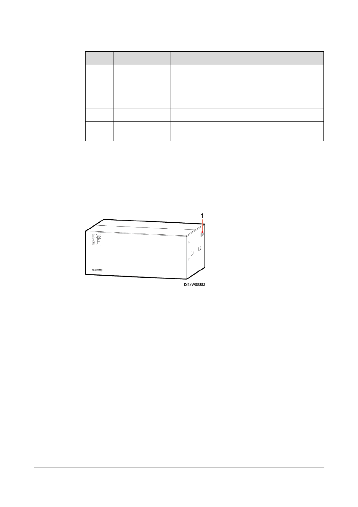
(1) Position of the model label
Model Identification
You can obtain the solar inverter model from the model label on the external package and the
nameplate on the side of the enclosure.
Figure 2-2 Position of the model label on the external package
SUN2000-(100KTL, 110KTL, 125KTL) Series
User Manual
2 Overview
Issue Preliminary Version 3.0
(2019-12-08)
Copyright © Huawei Technologies Co., Ltd.
9
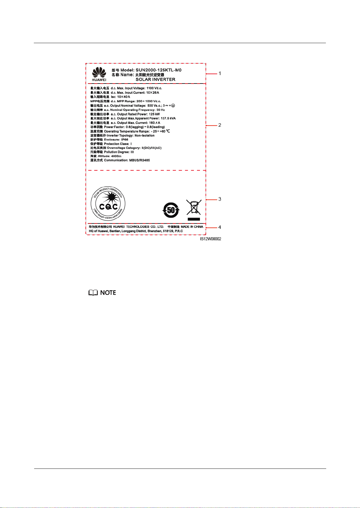
Figure 2-3 Nameplate
(1) Trademark and product model
(2) Key technical specifications
(3) Compliance symbols
(4) Company name and country of origin
The nameplate figure is for reference only.
2.2 Overview
Description
SUN2000 solar inverters are grid-tied PV string inverters that convert the DC power
generated by PV strings into AC power and feed the power into the power grid.
Characteristics
Smart
Ten independent maximum power point tracking (MPPT) circuits and 20 PV string
inputs. Flexible configuration of PV strings is supported.
Smart PV module self-learning: Automatically detects PV module failures, helping
rectify faults. Optimizes the working mode to obtain the optimal working mode of the
system.
SUN2000-(100KTL, 110KTL, 125KTL) Series
User Manual
2 Overview
Issue Preliminary Version 3.0
(2019-12-08)
Copyright © Huawei Technologies Co., Ltd.
10
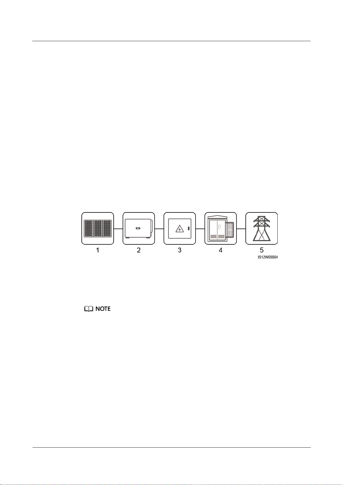
Networking
(1) PV string
(2) SUN2000
(3) AC combiner box
(4) Transformer station
(5) Power grid
Smart air cooling: Adjusts the fan speed based on the ambient temperature and load to
ensure the service life of fans and avoid frequent maintenance.
MBUS networking: Uses the existing power line for communication and does not require
additional communications cable, which reduces the construction and maintenance costs
and improves communication reliability and efficiency.
Smart I-V curve diagnosis: Implements I-V scanning and health diagnosis for PV strings.
In this way, potential risks and faults can be detected in time, improving the plant
operation & maintenance (O&M) quality.
Safe
Embedded DC and AC surge protection devices (SPDs): all-dimensional surge protection
Embedded residual current monitoring unit: Immediately disconnects from the power
grid upon detecting that the residual current exceeds the threshold.
SUN2000 solar inverters apply to grid-tied systems of large-scale PV plants and commercial
distributed grid-tied systems. Typically, a grid-tied PV system consists of the PV string, solar
inverter, AC combiner box, and transformer station.
Figure 2-4 Networking
The SUN2000-125KTL-M0 is powered by a dedicated power transformer instead of connecting to
low-voltage overhead power lines.
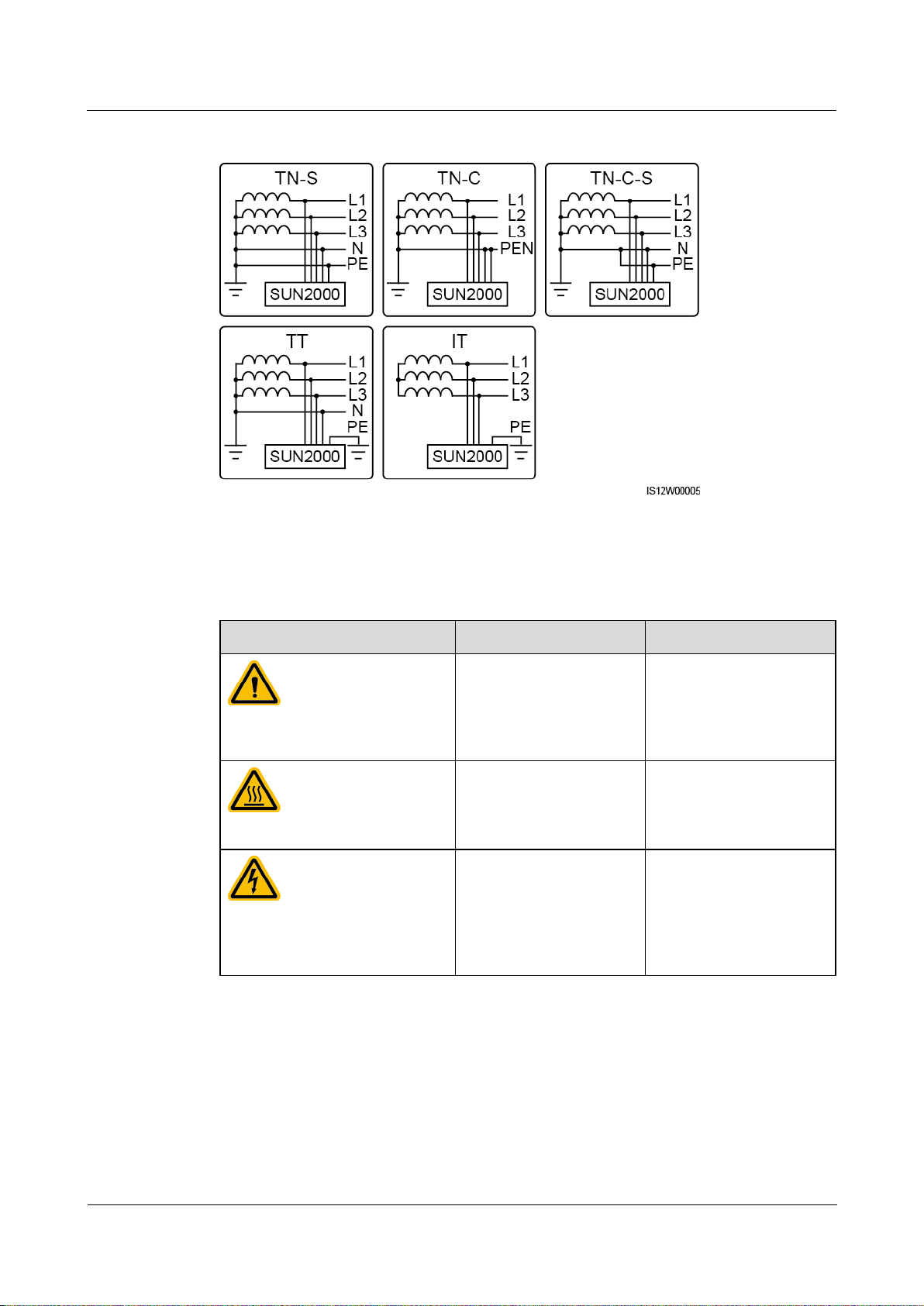
Supported Power Grids
SUN2000-110KTL-M0, SUN2000-100KTL-M0, SUN2000-100KTL-M1 and
SUN2000-100KTL-INM0 solar inverters support the TN-S, TN-C, TN-C-S, TT, and IT
power grids.
The SUN2000-125KTL-M0 supports only the IT power grid.
SUN2000-(100KTL, 110KTL, 125KTL) Series
User Manual
2 Overview
Issue Preliminary Version 3.0
(2019-12-08)
Copyright © Huawei Technologies Co., Ltd.
11
Figure 2-5 Supported Power Grids
Symbol
Name
Meaning
Running warning
Potential hazards exist
after the inverter is
powered on. Take
protective measures when
operating the inverter.
Burn warning
Do not touch a running
inverter, as the shell
becomes hot during
operation.
Large current warning
Before powering on the
inverter, ensure that the
inverter is grounded
because there is a large
contact current after the
inverter is powered on.
2.3 Label Description
SUN2000-(100KTL, 110KTL, 125KTL) Series
User Manual
2 Overview
Issue Preliminary Version 3.0
(2019-12-08)
Copyright © Huawei Technologies Co., Ltd.
12
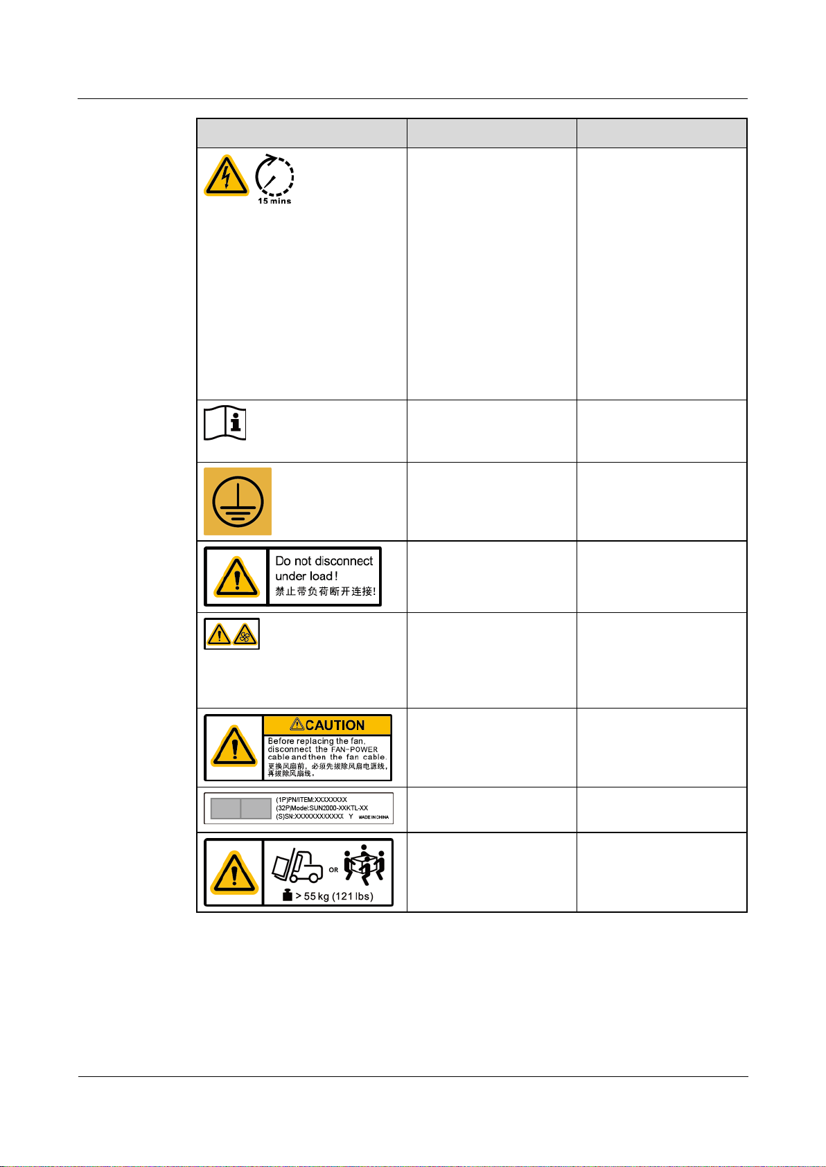
Symbol
Name
Meaning
Delayed discharge
High voltage exists
after the inverter is
powered on. Only
qualified and trained
electrical technicians
are allowed to perform
operations on the
inverter.
Residual voltage exists
after the inverter is
powered off. It takes
15 minutes for the
inverter to discharge to
the safe voltage.
Refer to documentation
Reminds operators to
refer to the documents
shipped with the inverter.
Grounding
Indicates the position for
connecting the protective
earthing (PE) cable.
Operation warning
Do not remove the DC
input connector when the
inverter is running.
Fan operation warning
High voltage exists after
the inverter is powered
on. Do not touch the fans
when the inverter is
working.
Fan replacement warning
Before replacing a fan,
disconnect its power
connectors.
Inverter ESN label
Indicates the inverter
serial number.
Weight label
The inverter needs to be
carried by four persons or
using a pallet truck.

SUN2000-(100KTL, 110KTL, 125KTL) Series
User Manual
2 Overview
Issue Preliminary Version 3.0
(2019-12-08)
Copyright © Huawei Technologies Co., Ltd.
13
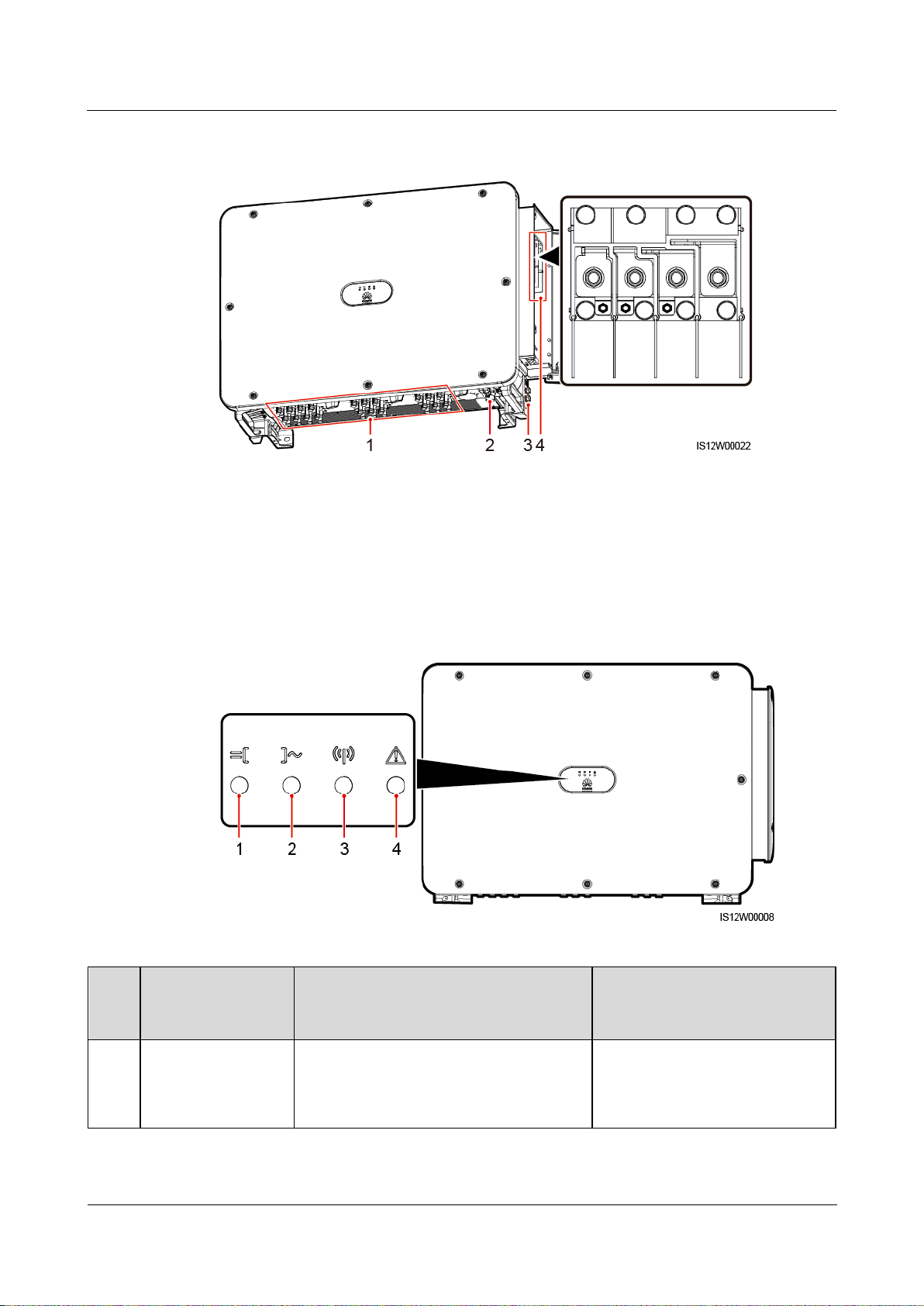
2.4 Product Appearance
(1) Panel
(2) LED indicators
(3) Maintenance compartment
door
(4) Mounting bracket
(5) External fan tray
(6) DC input terminal group 1 (PV1–PV8, controlled by
DC SWITCH 1)
(7) DC switch 1 (DC SWITCH
1)
(8) DC input terminal group 2 (PV9–PV14, controlled by
DC SWITCH 2)
(9) DC switch 2 (DC SWITCH
2)
(10) DC input terminal group 3 (PV15–PV20, controlled
by DC SWITCH 3)
(11) DC switch 3 (DC
SWITCH 3)
(12) Ventilation valve
(13) USB port (USB)
(14) Communications port (COM)
(15) Hole for the AC output
power cable
(16) Hole for the tracking system power cable
2.4.1 Product Appearance
Appearance
Figure 2-6 Appearance
SUN2000-(100KTL, 110KTL, 125KTL) Series
User Manual
2 Overview
Issue Preliminary Version 3.0
(2019-12-08)
Copyright © Huawei Technologies Co., Ltd.
14
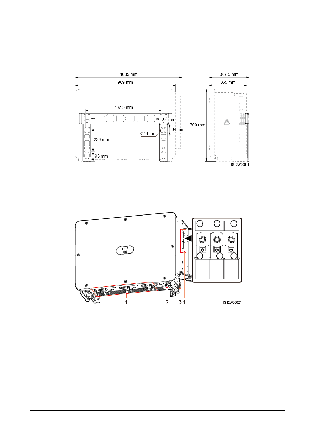
Dimensions
(1) DC input terminals
(2) RS485 port
(3) Ground point on the enclosure
(4) AC terminal block (3-pin)
Wiring Area
Figure 2-7 Dimensions
Figure 2-8 Wiring port of a 3-pin model (SUN2000-125KTL-M0)
SUN2000-(100KTL, 110KTL, 125KTL) Series
User Manual
2 Overview
Issue Preliminary Version 3.0
(2019-12-08)
Copyright © Huawei Technologies Co., Ltd.
15
Figure 2-9 Wiring port of 4-pin models (SUN2000-110KTL-M0, SUN2000-100KTL-M0,
(1) DC input terminals
(2) RS485 port
(3) Ground point on the enclosure
(4) AC terminal block (4-pin)
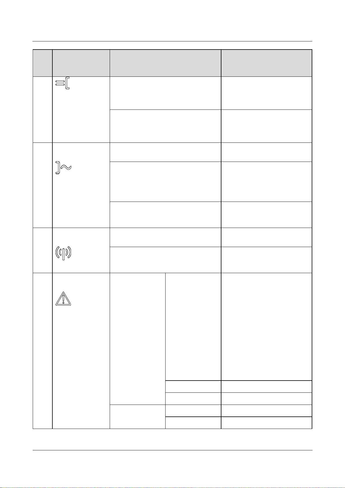
No.
Indicator
Status (Blinking Fast: On for 0.2s and
then Off for 0.2s; Blinking Slowly:
On for 1s and then Off for 1s)
Description
1
PV connection
indicator
Steady green
At least one PV string is properly
connected, and the DC input
voltage of the corresponding
MPPT circuit is at least 200 V.
SUN2000-100KTL-M1, and SUN2000-100KTL-INM0)
2.4.2 Indicator Status
Figure 2-10 Indicator
SUN2000-(100KTL, 110KTL, 125KTL) Series
User Manual
2 Overview
Issue Preliminary Version 3.0
(2019-12-08)
Copyright © Huawei Technologies Co., Ltd.
16
No.
Indicator
Status (Blinking Fast: On for 0.2s and
then Off for 0.2s; Blinking Slowly:
On for 1s and then Off for 1s)
Description
Blinking green fast
If the alarm/maintenance indicator
is red, an environmental fault at
the DC side of the solar inverter is
generated.
Off
The solar inverter disconnects
from all PV strings, or the DC
input voltage of all MPPT circuits
is less than 200 V.
2
Grid connection
indicator
Steady green
The solar inverter is in grid-tied
mode.
Blinking green fast
If the alarm/maintenance indicator
is red, an environmental fault
(excluding Grid Loss) at the AC
side of the solar inverter is
generated.
Off
The solar inverter is not in
grid-tied mode (due to reasons
including Grid Loss).
3
Communications
indicator
Blinking green fast
The solar inverter receives
communication data normally.
Off
The solar inverter has not received
communication data for 10
seconds.
4
Alarm/Maintenance
indicator
Alarm status
Steady red
A major alarm is generated.
If the PV connection indicator
or grid connection indicator is
blinking green fast,
troubleshoot DC or AC
environmental faults as
instructed by the SUN2000
app.
If the PV connection indicator
and grid connection indicator
are both not blinking green
fast, replace components or the
solar inverter as instructed by
the SUN2000 app.
Blinking red fast
A minor alarm is generated.
Blinking red slowly
A warning alarm is generated.
Local maintenance
status
Steady green
Local maintenance succeeds.
Blinking green fast
Local maintenance fails.
SUN2000-(100KTL, 110KTL, 125KTL) Series
User Manual
2 Overview
Issue Preliminary Version 3.0
(2019-12-08)
Copyright © Huawei Technologies Co., Ltd.
17
No.
Indicator
Status (Blinking Fast: On for 0.2s and
then Off for 0.2s; Blinking Slowly:
On for 1s and then Off for 1s)
Description
Blinking green
slowly
In local maintenance or shuts
down over a command.
The PV connection indicator and the grid connection indicator preferentially indicate environmental
faults.
Local maintenance refers to operations performed after a USB flash drive, a WLAN module, a
Bluetooth module, or a USB data cable is inserted into the USB port of the solar inverter. For
example, local maintenance includes data import and export using a USB flash drive, and connecting
to the SUN2000 app over a WLAN module, a Bluetooth module, or a USB data cable.
If an alarm is generated during local maintenance, the alarm/maintenance indicator shows the local
maintenance state first. After the USB flash drive, WLAN module, Bluetooth module, or USB data
cable is removed, the indicator shows the alarm state.
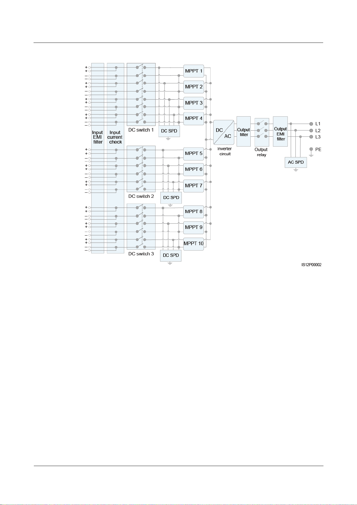
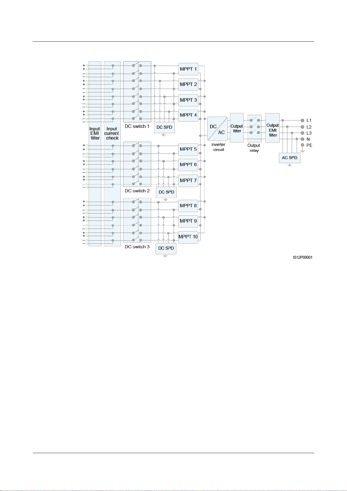
2.5 Working Principles
2.5.1 Circuit Diagram
The solar inverter receives inputs from 20 PV strings. The inputs are grouped into 10 MPPT
circuits inside the solar inverter to track the maximum power point of the PV strings. The DC
power is then converted into three-phase AC power through an inverter circuit. Surge
protection is supported on both the DC and AC sides.
SUN2000-(100KTL, 110KTL, 125KTL) Series
User Manual
2 Overview
Issue Preliminary Version 3.0
(2019-12-08)
Copyright © Huawei Technologies Co., Ltd.
18
Figure 2-11 Schematic diagram of a 3-pin model
SUN2000-(100KTL, 110KTL, 125KTL) Series
User Manual
2 Overview
Issue Preliminary Version 3.0
(2019-12-08)
Copyright © Huawei Technologies Co., Ltd.
19
Figure 2-12 Schematic diagram of 4-pin models
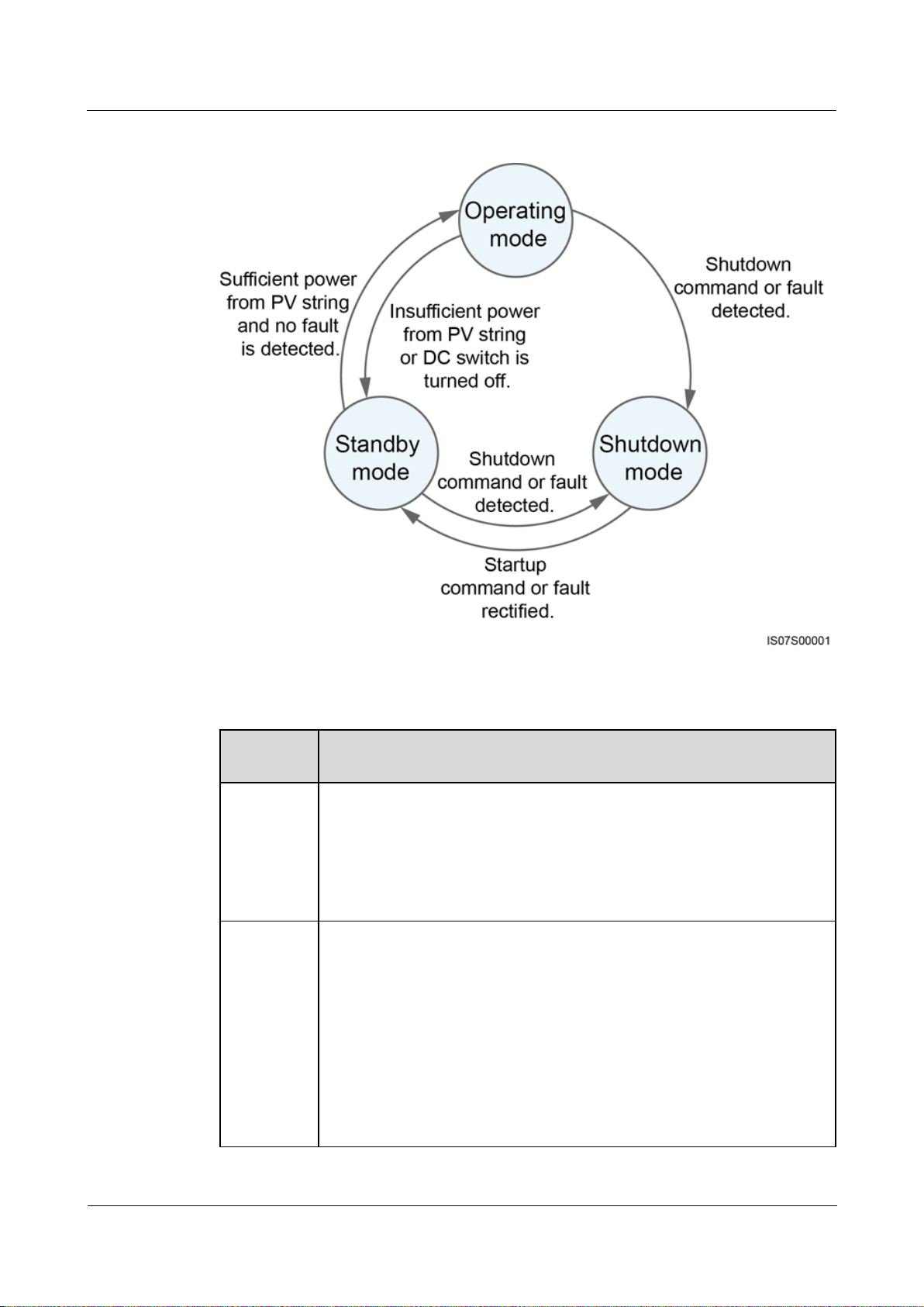
2.5.2 Working Modes
The SUN2000 can work in Standby, Operating, or Shutdown mode.
SUN2000-(100KTL, 110KTL, 125KTL) Series
User Manual
2 Overview
Issue Preliminary Version 3.0
(2019-12-08)
Copyright © Huawei Technologies Co., Ltd.
20
Figure 2-13 Working modes
Working
Mode
Description
Standby
The SUN2000 enters Standby mode when the external environment does not
meet the operating requirements. In Standby mode:
The SUN2000 continuously performs status check and enters the
Operating mode once the operating requirements are met.
The SUN2000 enters Shutdown mode after detecting a shutdown
command or a fault after startup.
Operating
In Operating mode:
The SUN2000 converts DC power from PV strings into AC power and
feeds the power to the power grid.
The SUN2000 tracks the maximum power point to maximize the PV
string output.
If the SUN2000 detects a fault or a shutdown command, it enters the
Shutdown mode.
The SUN2000 enters Standby mode after detecting that the PV string
output power is not suitable for connecting to the power grid for
generating power.
Table 2-2 Working mode description
SUN2000-(100KTL, 110KTL, 125KTL) Series
User Manual
2 Overview
Issue Preliminary Version 3.0
(2019-12-08)
Copyright © Huawei Technologies Co., Ltd.
21
Working
Mode
Description
Shutdown
In Standby or Operating mode, the SUN2000 enters Shutdown mode
after detecting a fault or shutdown command.
In Shutdown mode, the SUN2000 enters Standby mode after detecting a
startup command or that the fault is rectified.
SUN2000-(100KTL, 110KTL, 125KTL) Series
User Manual
3 Solar Inverter Storage
Issue Preliminary Version 3.0
(2019-12-08)
Copyright © Huawei Technologies Co., Ltd.
22
3 Solar Inverter Storage
The following requirements should be met if the solar inverter is not put into use immediately:
Do not remove the packing materials, and check the packing materials regularly
(recommended: every three months). If any rodent bites are found, replace the packing
materials immediately. If the solar inverter is unpacked but not put into use immediately,
put it inside the original package with the desiccant bag, and seal it using tape.
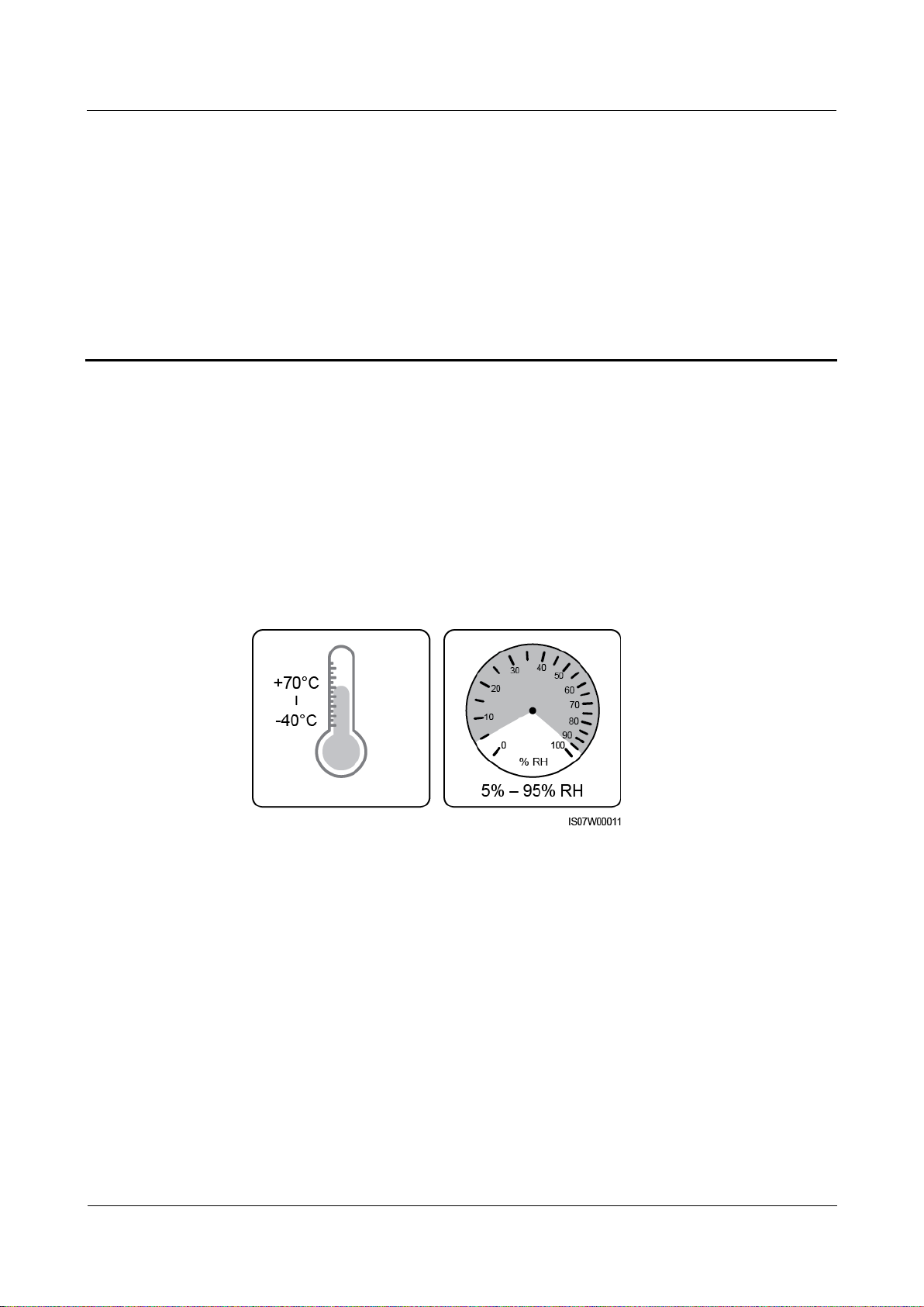
The ambient temperature and humidity should be suitable for the storage. The air must
not contain corrosive or flammable gases.
Figure 3-1 Storage temperature and humidity
The solar inverter should be stored in a clean and dry place and be protected from dust
and water vapor corrosion. The solar inverter must be protected against rain and water.
Do not tilt the package or place it upside down.
To avoid personal injury or device damage, stack inverters with caution to prevent them
from falling over.

SUN2000-(100KTL, 110KTL, 125KTL) Series
User Manual
3 Solar Inverter Storage
Issue Preliminary Version 3.0
(2019-12-08)
Copyright © Huawei Technologies Co., Ltd.
23
Figure 3-2 Maximum number of pile-up layers allowed
If the solar inverter has been stored for more than two years, it must be checked and
tested by professionals before being put into use.

SUN2000-(100KTL, 110KTL, 125KTL) Series
User Manual
4 Installation
Issue Preliminary Version 3.0
(2019-12-08)
Copyright © Huawei Technologies Co., Ltd.
24
4.1 Check Before Installation
Category
Tool
Installation tools
Hammer drill (with
Ф14 mm and Ф16
mm drill bits)
Socket wrench set
Torque wrench
Torque screwdriver
(Phillips head: M3
and M4; flat head:
M3 and M4)
Checking Outer Packing Materials
Before unpacking the solar inverter, check the outer packing materials for damage, such as
holes and cracks, and check the solar inverter model. If any damage is found or the solar
inverter model is not what you requested, do not unpack the package and contact your
supplier as soon as possible.
4 Installation
You are advised to remove the packing materials within 24 hours before installing the solar inverter.
Checking Accessories
After unpacking the solar inverter, check that the components are intact and complete. If any
damage is found or any component is missing, contact your dealer.
For details about the number of accessories delivered with the solar inverter, see the Packing List in the
packing case.
4.2 Tools

SUN2000-(100KTL, 110KTL, 125KTL) Series
User Manual
4 Installation
Issue Preliminary Version 3.0
(2019-12-08)
Copyright © Huawei Technologies Co., Ltd.
25
Category
Tool
Diagonal pliers
Wire strippers
Flat-head
screwdriver (head:
M3)
Rubber mallet
Utility knife
Cable cutter
Crimping tool
(model:
PV-CZM-22100)
RJ45 crimping tool
Open-end wrench
(model: PV-MS)
Vacuum cleaner
Multimeter (DC
voltage
measurement range
≥ 1100 V DC)
Marker
Measuring tape
Bubble or digital
level
Hydraulic pliers
Heat shrink tubing
Heat gun
Cable tie
Scissors
N/A

SUN2000-(100KTL, 110KTL, 125KTL) Series
User Manual
4 Installation
Issue Preliminary Version 3.0
(2019-12-08)
Copyright © Huawei Technologies Co., Ltd.
26
Category
Tool
Personal protective
equipment (PPE)
Safety gloves
Safety goggles
Anti-dust respirator
Safety boots
4.3 Determining the Installation Position
Installation Environment Requirements
The solar inverter can be installed indoors or outdoors.
Do not install the solar inverter near flammable or explosive materials.
Do not install the solar inverter where its enclosure and heat sink are easily accessible,
because the voltage is high and these parts are hot during operation.
Install the solar inverter in a well-ventilated environment for heat dissipation
When the solar inverter is installed under direct sunlight, the power may be derated due
to the temperature rise. You are advised to install the solar inverter in a sheltered place or
install an awning over it.
The SUN2000-125KTL-M0 should be physically separated from third-party wireless
communication facilities and residential environments by distance greater than 30 m.
Figure 4-1 Installation environment

SUN2000-(100KTL, 110KTL, 125KTL) Series
User Manual
4 Installation
Issue Preliminary Version 3.0
(2019-12-08)
Copyright © Huawei Technologies Co., Ltd.
27
Mounting Structure Requirements
The mounting structure where the solar inverter is installed must be fire resistant. Do not
install the solar inverter on flammable building materials.
Ensure that the installation surface is solid enough to bear the solar inverter.
In residential areas, do not install the solar inverter on drywalls or walls made of similar
materials with a weak sound insulation performance because the noise generated by the
solar inverter may interfere with residents.
Figure 4-2 Mounting structure
Installation Angle Requirements
The solar inverter can be support-mounted or wall-mounted. The installation angle
requirements are as follows:
Install the solar inverter vertically or at a maximum back tilt of 75 degrees to facilitate
heat dissipation.
Do not install the solar inverter at forward tilted, excessive back tilted, side tilted,
horizontal, or upside down positions.

SUN2000-(100KTL, 110KTL, 125KTL) Series
User Manual
4 Installation
Issue Preliminary Version 3.0
(2019-12-08)
Copyright © Huawei Technologies Co., Ltd.
28
Figure 4-3 Angle
Installation Dimensions Requirements
Reserve enough space around the solar inverter for installation and heat dissipation.
Figure 4-4 Installation dimensions

SUN2000-(100KTL, 110KTL, 125KTL) Series
User Manual
4 Installation
Issue Preliminary Version 3.0
(2019-12-08)
Copyright © Huawei Technologies Co., Ltd.
29
For ease of installing the solar inverter on the mounting bracket, connecting cables to the bottom of the
solar inverter, and maintaining the solar inverter in future, it is recommended that the bottom clearance
be between 600 mm and 730 mm. If you have any question about the clearance, consult the local
technical support engineers.
When installing multiple solar inverters, install them in horizontal mode if sufficient space is
available and install them in triangle mode if no sufficient space is available. Stacked
installation is not recommended.
Figure 4-5 Horizontal installation mode (recommended)
Figure 4-6 Triangle installation mode (recommended)

SUN2000-(100KTL, 110KTL, 125KTL) Series
User Manual
4 Installation
Issue Preliminary Version 3.0
(2019-12-08)
Copyright © Huawei Technologies Co., Ltd.
30
Figure 4-7 Stacked installation mode (not recommended)
(1) Security Torx wrench
4.4 Installing the Mounting Bracket
Before installing the mounting bracket, remove the security Torx wrench and keep it for later
use.
Figure 4-8 Position for binding the security Torx wrench
The mounting bracket of the solar inverter has four groups of tapped holes, each group
containing four tapped holes. Mark any hole in each group based on site requirements and
mark four holes in total. The two round holes are recommended.

SUN2000-(100KTL, 110KTL, 125KTL) Series
User Manual
4 Installation
Issue Preliminary Version 3.0
(2019-12-08)
Copyright © Huawei Technologies Co., Ltd.
31
Figure 4-9 Hole dimensions
4.4.1 Support-mounted Installation
Prerequisites
M12x40 bolt assemblies are supplied with the mounting bracket. If the bolt length does not
meet the installation requirements, prepare M12 bolt assemblies by yourself and use them
together with the supplied M12 nuts.
Procedure
Step 1 Determine the positions for drilling holes using the mounting bracket. Level the positions of
Step 2 Drill holes using a hammer drill. It is recommended that anti-rust measures be taken on the
Step 3 Secure the mounting bracket.
mounting holes using a bubble or digital level, and mark the positions with a marker.
positions for drilling holes.
Figure 4-10 Installing the mounting bracket
----End

SUN2000-(100KTL, 110KTL, 125KTL) Series
User Manual
4 Installation
Issue Preliminary Version 3.0
(2019-12-08)
Copyright © Huawei Technologies Co., Ltd.
32
4.4.2 Wall-mounted Installation
Prerequisites
You have prepared expansion bolts. M12x60 stainless steel expansion bolts are recommended.
Procedure
Step 1 Determine the positions for drilling holes using the mounting bracket. Level the positions of
mounting holes using a bubble or digital level, and mark the positions with a marker.
Step 2 Drill holes using a hammer drill and install expansion bolts.
Avoid drilling holes in the position of the wall with water pipes and power cables buried
inside.
To prevent dust inhalation or contact with eyes, wear safety goggles and an anti-dust
respirator when drilling holes.
Clean up any dust in and around the holes using a vacuum cleaner and measure the
distance between holes. If the holes are inaccurately positioned, drill a new set of holes.
Level the head of the expansion sleeve with the concrete wall after removing the bolt,
spring washer, and flat washer. Otherwise, the mounting bracket will not be securely
installed on the wall.
Step 3 Secure the mounting bracket.

SUN2000-(100KTL, 110KTL, 125KTL) Series
User Manual
4 Installation
Issue Preliminary Version 3.0
(2019-12-08)
Copyright © Huawei Technologies Co., Ltd.
33
Figure 4-11 Installing the mounting bracket
----End
4.5 Installing a Solar Inverter
Context

SUN2000-(100KTL, 110KTL, 125KTL) Series
User Manual
4 Installation
Issue Preliminary Version 3.0
(2019-12-08)
Copyright © Huawei Technologies Co., Ltd.
34
(A) Transportation scenario
(B) Installation scenario
Move the solar inverter with care to prevent device damage and personal injury.
It takes multiple persons or a pallet truck to move the solar inverter.
Do not use the ports and wiring terminals at the bottom to support any weight of the solar
inverter.
When you need to temporally place the solar inverter on the ground, use foam, paper, or
other protection material to prevent damage to its cover.
Use the handles to facilitate installation. Handles are optional and delivered separately.
Ensure that the handles are securely installed. After the installation is complete, remove
the handles and keep them properly.
To avoid damage to the equipment, do not lift or hoist a solar inverter with an improper
hold as shown in Figure 4-13.
Figure 4-12 Positions for installing the handles
Procedure
Step 1 Lift the solar inverter from the packing case and move it to the installation position.
Figure 4-13 Lifting positions

SUN2000-(100KTL, 110KTL, 125KTL) Series
User Manual
4 Installation
Issue Preliminary Version 3.0
(2019-12-08)
Copyright © Huawei Technologies Co., Ltd.
35
Figure 4-14 Taking out the solar inverter
Step 2 Lift the solar inverter and keep it upright.
Figure 4-15 Lifting the solar inverter and keeping it upright
Step 3 If the installation position is too high to install the solar inverter on the mounting bracket, run
a rope that is strong enough to bear the solar inverter through the two lifting eyes, and hoist
the solar inverter.
Hoist the solar inverter with care to protect it from colliding with the wall or other objects.

SUN2000-(100KTL, 110KTL, 125KTL) Series
User Manual
4 Installation
Issue Preliminary Version 3.0
(2019-12-08)
Copyright © Huawei Technologies Co., Ltd.
36
Figure 4-16 Hoisting the solar inverter
Step 4 Install the solar inverter on the mounting bracket and align the solar inverter enclosure with
the mounting bracket.
Figure 4-17 Mounting the solar inverter
Step 5 Secure the solar inverter.

SUN2000-(100KTL, 110KTL, 125KTL) Series
User Manual
4 Installation
Issue Preliminary Version 3.0
(2019-12-08)
Copyright © Huawei Technologies Co., Ltd.
37
Precautions
Figure 4-18 Tightening security Torx screws
----End
If the equipment is installed in a public place or in an area of people activities, such as a
parking lot, station, factory building, or residential area, install a protective net outside the
equipment and erect a safety warning sign to isolate the equipment. The purpose is to
avoid personal injury or property loss caused by contact with the equipment by
nonprofessionals or other reasons during the operation of the equipment.
If the solar inverter has not been running for more than half a year after being mounted, it
must be checked and tested by professionals before being put into operation.

SUN2000-(100KTL, 110KTL, 125KTL) Series
User Manual
5 Electrical Connections
Issue Preliminary Version 3.0
(2019-12-08)
Copyright © Huawei Technologies Co., Ltd.
38
5.1 Precautions
After the PV array receives solar irradiance, it transmits the DC voltage to the solar inverter.
Before connecting cables, ensure that the three DC switches on the solar inverter are set to
OFF. Otherwise, the high voltage of the solar inverter may result in electric shocks.
5 Electrical Connections
The device damage caused by incorrect cable connections is beyond the warranty scope.
Only qualified technicians can perform operations about electrical connection.
Wear proper PPE at all time when connecting cables.
To prevent poor cable connection due to overstress, leave enough slack before connecting
the cables to the appropriate ports.
The cable colors shown in the electrical connection diagrams provided in this chapter are for reference
only. Select cables in accordance with local cable specifications (green-and-yellow cables are only used
for protective earthing).
5.2 Preparing Cables
SUN2000 solar inverters support RS485 communication and MBUS communication.
The MBUS communication is applicable to medium-voltage grid connection scenarios and
non-low-voltage public grid connection scenarios (industrial environment).

SUN2000-(100KTL, 110KTL, 125KTL) Series
User Manual
5 Electrical Connections
Issue Preliminary Version 3.0
(2019-12-08)
Copyright © Huawei Technologies Co., Ltd.
39
(A) PV string
(B) SUN2000
(C) AC combiner box
(D) Transformer station
(E) Power grid
(F) SmartLogger
(G) Management system
In the networking diagram, indicates the power cable, indicates the power flow direction,
and and indicate the signal flow.
Figure 5-1 RS485 networking (SmartLogger)

SUN2000-(100KTL, 110KTL, 125KTL) Series
User Manual
5 Electrical Connections
Issue Preliminary Version 3.0
(2019-12-08)
Copyright © Huawei Technologies Co., Ltd.
40
Figure 5-2 RS485 networking (SDongle)
(A) PV string
(B) SUN2000
(C) AC combiner box
(D) Transformer station
(E) Power grid
(F) SDongle
(G) Management system
(A) PV string
(B) SUN2000
(C) AC combiner box
(D) Transformer station
(E) Power grid
(F) SmartLogger
Figure 5-3 MBUS networking (SmartLogger)

SUN2000-(100KTL, 110KTL, 125KTL) Series
User Manual
5 Electrical Connections
Issue Preliminary Version 3.0
(2019-12-08)
Copyright © Huawei Technologies Co., Ltd.
41
(G) Management system
(A) PV string
(B) SUN2000
(C) AC combiner box
(D) Transformer station
(E) Power grid
(F) SDongle
(G) Management system
Figure 5-4 MBUS networking (SDongle)

SUN2000-(100KTL, 110KTL, 125KTL) Series
User Manual
5 Electrical Connections
Issue Preliminary Version 3.0
(2019-12-08)
Copyright © Huawei Technologies Co., Ltd.
42
No.
Component
Description
Source
A
PV string
PV strings consist of PV modules in
series.
A solar inverter supports 20 PV string
inputs.
Prepared by the
customer
To ensure the system response speed, it is recommended that less than 30 solar inverters be
connected to each COM port on the SmartLogger and that less than 10 solar inverters be
cascaded over the SDongle.
The RS485 communication distance between the last solar inverter and the SmartLogger
cannot exceed 1000 m.
Figure 5-5 Cable connections (configure the components in the dotted box as required)
Table 5-1 Components

SUN2000-(100KTL, 110KTL, 125KTL) Series
User Manual
5 Electrical Connections
Issue Preliminary Version 3.0
(2019-12-08)
Copyright © Huawei Technologies Co., Ltd.
43
No.
Component
Description
Source
B
Environmental monitoring
instrument (EMI)
When the SmartLogger is used, the EMI
can be directly connected to the
SmartLogger or connected to the last
solar inverter cascaded over RS485.
When the SDongle is used, the EMI is a
cascaded device that needs to be
connected to the solar inverter where the
SDongle is installed.
Prepared by the
customer
C
SmartLogger
The solar inverter communicates with the
management system through the
SmartLogger.
Purchased from
Huawei
D
Power Meter
Implements power control at the grid-tied
point in low voltage scenarios using a power
meter.
Prepared by the
customer
E
Support tracking system
Adjusts the angle of the supports.
Prepared by the
customer
F
Fuse/Circuit breaker
The tracking system should be equipped with
an overcurrent protection device or
component. The power cable between the
device or component and the wiring terminal
should be no longer than 2.5 m.
Therefore, a fuse or a circuit breaker is
recommended.
Installed between the solar inverter and
tracking control box
Fuse specifications: rated voltage ≥ 500
V; rated current: 16 A; protection: gG
Circuit breaker specifications: rated
voltage ≥ 500 V; rated current: 16 A;
tripping: C
Prepared by the
customer
G
AC switch
Installed in the AC combiner box
Recommended: a three-phase AC circuit
breaker with a rated voltage greater than
or equal to 500 V AC and a rated current
of 250 A
Prepared by the
customer
H
SDongle
The solar inverter communicates with the
management system through the SDongle.
Purchased from
Huawei
The solar inverter has an RCMU inside. Its external AC switch should be a three-phase circuit
breaker or other AC load circuit breakers to safely disconnect the solar inverter from the
power grid.

SUN2000-(100KTL, 110KTL, 125KTL) Series
User Manual
5 Electrical Connections
Issue Preliminary Version 3.0
(2019-12-08)
Copyright © Huawei Technologies Co., Ltd.
44
Table 5-2 Cable description of a 3-pin model (S: cross-sectional area of the AC cable conductor; Sp: cross-sectional
No.
Cable
Category
Conductor
Cross-Sectional
Area Range
Outer
Diameter
Source
1
DC input power
cable
PV cable that meets the 1100
V standard
4–6 mm2
5.5–9 mm
Prepared
by the
customer
2
RS485
communications
cable
Outdoor shielded twisted
pair that meets the local
standard
0.25–1 mm2
One or two
communicat
ions cables:
4–11 mm
Three
communicat
ions cables:
4–8 mm
Prepared
by the
customer
3
Protective
earthing (PE)
cable
Single-core outdoor copper
cable and M10 OT/DT
terminals
NOTICE
You are advised to choose the
ground point on the enclosure.
The ground point in the
maintenance compartment is
used for connecting to the PE
cable contained in the
multi-core AC power cable.
Sp ≥ S/2
N/A
Prepared
by the
customer
4
Tracking system
power cable
Three-core outdoor copper
cable with dual-layer
protection
10 mm2
15–18 mm
Prepared
by the
customer
5
AC output
power cable
(multi-core)
If you connect a PE cable
to the ground point on the
enclosure, you are
advised to use a
three-core (L1, L2, and
L3) outdoor cable and
M12 OT/DT terminals
(L1, L2, and L3).
If you connect a PE cable
to the ground point in the
maintenance
compartment, you are
advised to use a four-core
(L1, L2, L3, and PE)
outdoor cable, M12
OT/DT terminals (L1,
L2, and L3), and M10
OT/DT terminals (PE).
You do not need to
prepare a PE cable.
Copper cable:
− S: 70–240
mm2
− S
p
≥ S/2
Aluminum
alloy cable or
copper-clad
aluminum
cable:
− S: 95–240
mm2
− S
p
≥ S/2
24–66 mm
Prepared
by the
customer
area of the protective earthing cable conductor)

SUN2000-(100KTL, 110KTL, 125KTL) Series
User Manual
5 Electrical Connections
Issue Preliminary Version 3.0
(2019-12-08)
Copyright © Huawei Technologies Co., Ltd.
45
No.
Cable
Category
Conductor
Cross-Sectional
Area Range
Outer
Diameter
Source
AC output
power cable
(single-core)
You are advised to use a
single-core outdoor cable
and M12 OT/DT terminals.
Copper cable:
− S: 70–240
mm2
Aluminum
alloy cable or
copper-clad
aluminum
cable:
− S: 95–240
mm2
14–32 mm
Prepared
by the
customer
The value of Sp is valid only if the conductors of the PE cable and AC power cable use the same material. If the
materials are different, ensure that the conductor of the PE cable with a proper cross-sectional area produces a
conductance equivalent to that of the cable specified in the table.
No.
Cable
Category
Conductor
Cross-Sectional
Area Range
Outer
Diameter
Source
1
DC input power
cable
PV cable that meets the 1100
V standard
4–6 mm2
5.5–9 mm
Prepared
by the
customer
2
RS485
communications
cable
Outdoor shielded twisted
pair that meets the local
standard
0.25–1 mm2
One or two
communicat
ions cables:
4–11 mm
Three
communicat
ions cables:
4–8 mm
Prepared
by the
customer
3
PE cable
Single-core outdoor copper
cable and M10 OT/DT
terminals
NOTICE
You are advised to choose the
ground point on the enclosure.
The ground point in the
maintenance compartment is
used for connecting to the PE
cable contained in the
multi-core AC power cable.
Sp ≥ S/2
N/A
Prepared
by the
customer
Table 5-3 Cable description of 4-pin models (S: cross-sectional area of the AC cable conductor; Sp: cross-sectional area
of the PE cable conductor)

SUN2000-(100KTL, 110KTL, 125KTL) Series
User Manual
5 Electrical Connections
Issue Preliminary Version 3.0
(2019-12-08)
Copyright © Huawei Technologies Co., Ltd.
46
No.
Cable
Category
Conductor
Cross-Sectional
Area Range
Outer
Diameter
Source
4
Tracking system
power cable
Three-core outdoor copper
cable with dual-layer
protection
10 mm2
15–18 mm
Prepared
by the
customer
5
AC output
power cable
(multi-core)
If you connect a PE cable
to the ground point on the
enclosure and the neutral
wire is not used, you are
advised to use a
three-core (L1, L2, and
L3) outdoor cable and
M12 OT/DT terminals
(L1, L2, and L3).
If you connect a PE cable
to the ground point in the
maintenance
compartment and the
neutral wire is not used,
you are advised to use a
four-core (L1, L2, L3,
and PE) outdoor cable,
M12 OT/DT terminals
(L1, L2, and L3), and
M10 OT/DT terminals
(PE).
If you connect a PE cable
to the ground point on the
enclosure and the neutral
wire is used, you are
advised to use a four-core
(L1, L2, L3, and N)
outdoor cable and M12
OT/DT terminals (L1,
L2, L3, and N).
If you connect a PE cable
to the ground point in the
maintenance
compartment and the
neutral wire is used, you
are advised to use a
five-core (L1, L2, L3, N,
and PE) outdoor cable,
M12 OT/DT terminals
(L1, L2, L3, and N), and
M10 OT/DT terminals
(PE).
Copper cable:
− S: 70–240
mm2
− S
p
≥ S/2
Aluminum
alloy cable or
copper-clad
aluminum
cable:
− S: 95–240
mm2
− S
p
≥ S/2
24–66 mm
Prepared
by the
customer

SUN2000-(100KTL, 110KTL, 125KTL) Series
User Manual
5 Electrical Connections
Issue Preliminary Version 3.0
(2019-12-08)
Copyright © Huawei Technologies Co., Ltd.
47
No.
Cable
Category
Conductor
Cross-Sectional
Area Range
Outer
Diameter
Source
AC output
power cable
(single-core)
You are advised to use a
single-core outdoor cable
and M12 OT/DT terminals.
Copper cable:
− S: 70–240
mm2
Aluminum
alloy cable or
copper-clad
aluminum
cable:
− S: 95–240
mm2
14–32 mm
Prepared
by the
customer
The value of Sp is valid only if the conductors of the PE cable and AC power cable use the same material. If the
materials are different, ensure that the conductor of the PE cable with a proper cross-sectional area produces a
conductance equivalent to that of the cable specified in the table.
5.3 Connecting the PE Cable
Context
Proper grounding is helpful for resisting the impact of surge voltage and improving the
electromagnetic interference (EMI) performance. Before connecting the AC power cable,
DC power cables, and communications cable, connect the PE cable to the PE point.
It is recommended that the PE cable of the solar inverter be connected to a nearby ground
point. Connect the PE points of all solar inverters in the same array to ensure equipotential
connections to PE cables.
Procedure
Step 1 Connect the PE cable to the PE point.

SUN2000-(100KTL, 110KTL, 125KTL) Series
User Manual
5 Electrical Connections
Issue Preliminary Version 3.0
(2019-12-08)
Copyright © Huawei Technologies Co., Ltd.
48
Figure 5-6 Connecting the PE cable to the PE point (on the enclosure)
(1) Reserved PE point
----End
Follow-up Procedure
To enhance the corrosion resistance of a ground terminal, apply silica gel or paint on it after
connecting the PE cable.
5.4 Opening the Maintenance Compartment Door
Precautions
Do not open the panel cover of the solar inverter.
Before opening the maintenance compartment door, ensure that no electrical connections
are made for the solar inverter on the AC or DC side.
If you need to open the maintenance compartment door in rainy or snowy days, take
protective measures to prevent rain or snow from entering the maintenance compartment.
If unavoidable, do not open the maintenance compartment door.
Do not leave unused screws in the maintenance compartment.
Procedure
Step 1 Open the maintenance compartment door and install the support bar.

SUN2000-(100KTL, 110KTL, 125KTL) Series
User Manual
5 Electrical Connections
Issue Preliminary Version 3.0
(2019-12-08)
Copyright © Huawei Technologies Co., Ltd.
49
Figure 5-7 Opening the maintenance compartment door
Step 2 Remove the accessories and keep them properly.
Figure 5-8 Removing the accessories
Step 3 Select a crimping module according to the type of the AC output power cable.

SUN2000-(100KTL, 110KTL, 125KTL) Series
User Manual
5 Electrical Connections
Issue Preliminary Version 3.0
(2019-12-08)
Copyright © Huawei Technologies Co., Ltd.
50
Figure 5-9 Select the crimping module
(A) Crimping
module for
multi-core cables of
a 3-pin model
(B) Crimping
module for
single-core cables of
a 3-pin model
(C) Crimping
module for
multi-core cables of
4-pin models
(D) Crimping
module for
single-core cables of
4-pin models
----End
Follow-up Procedure
Use scissors to cut off the joints of the rubber rings to remove them. All rubber rings are
removed in the same way.
Remove the corresponding rubber rings in strict accordance with the cable diameter, and
ensure that the crimping module is not damaged. Otherwise the protection level of the solar
inverter will be affected.
Figure 5-10 Remove the rubber ring

SUN2000-(100KTL, 110KTL, 125KTL) Series
User Manual
5 Electrical Connections
Issue Preliminary Version 3.0
(2019-12-08)
Copyright © Huawei Technologies Co., Ltd.
51
5.5 (Optional) Installing the Power Cable of the Tracking System
Precautions
The tracking system obtains power from the AC three-phase power grid. The rated voltage
of the power supply is the rated output voltage of the solar inverter.
Keep inflammable materials away from the power cable.
The power cable must be protected with a conduit to prevent short circuits caused by
insulation layer damage.
Connect the power cable of the tracking system before the AC output power cable.
Otherwise, reworking will be caused.
Procedure
Step 1 Prepare a cable.
Step 2 Remove the corresponding rubber rings.
Step 3 Connect the power cable of the tracking system.
Figure 5-11 Connecting the power cable of the tracking system
----End

SUN2000-(100KTL, 110KTL, 125KTL) Series
User Manual
5 Electrical Connections
Issue Preliminary Version 3.0
(2019-12-08)
Copyright © Huawei Technologies Co., Ltd.
52
5.6 Connecting an AC Output Power Cable
(1) Power cable of the tracking system
(2) AC output power cable
Prerequisites
A three-phase AC switch should be installed on the AC side of the solar inverter. To
ensure that the solar inverter can safely disconnect itself from the power grid when an
exception occurs, select a proper overcurrent protection device in compliance with local
power distribution regulations.
Connect the AC output power cable according to the requirements specified by local
power grid operators.
Connect the power cable of the tracking system before the AC output power cable.
Otherwise, reworking will be caused.
Figure 5-12 Cable connection sequence
Do not connect loads between the solar inverter and the AC switch.
Requirements for the OT/DT Terminal
If a copper cable is used, use copper wiring terminals.
If a copper-clad aluminum cable is used, use copper wiring terminals.
If an aluminum alloy cable is used, use copper-aluminum transition wiring terminals, or
aluminum wiring terminals along with copper-aluminum transition spacers.

SUN2000-(100KTL, 110KTL, 125KTL) Series
User Manual
5 Electrical Connections
Issue Preliminary Version 3.0
(2019-12-08)
Copyright © Huawei Technologies Co., Ltd.
53
Do not connect aluminum wiring terminals to the AC terminal block. Otherwise the
electrochemical corrosion will occur and affect the reliability of cable connections.
Comply with the IEC61238-1 requirements when using copper-aluminum transition wiring
terminals, or aluminum wiring terminals along with copper-aluminum transition spacers.
If copper-aluminum transition spacers are used, pay attention to the front and rear sides.
Ensure that the aluminum sides of spacers are in contact with aluminum wiring terminals,
and copper sides of spacers are in contact with the AC terminal block.
Figure 5-13 Requirements for the OT/DT terminal

SUN2000-(100KTL, 110KTL, 125KTL) Series
User Manual
5 Electrical Connections
Issue Preliminary Version 3.0
(2019-12-08)
Copyright © Huawei Technologies Co., Ltd.
54
Figure 5-14 AC terminal block dimensions of a 3-pin model
Figure 5-15 AC terminal block dimensions of 4-pin models
This section describes how to install an AC output power cable for the 3-pin model.
Procedure
Step 1 Prepare a cable.
Step 2 Remove rubber rings according to the cable diameter range.
Step 3 Secure the AC output power cable and PE cable.
Step 4 Install the support bar.
Step 5 Close the maintenance compartment door and tighten the two screws on the door.

SUN2000-(100KTL, 110KTL, 125KTL) Series
User Manual
5 Electrical Connections
Issue Preliminary Version 3.0
(2019-12-08)
Copyright © Huawei Technologies Co., Ltd.
55
Sufficient slack should be provided in the PE cable to ensure that the last cable bearing the
force is the PE cable when the AC output power cable bears pulling force due to force
majeure.
The cable outer diameter can be measured using the ruler sticker in the maintenance
compartment.
Ensure that the cable jacket is in the maintenance compartment.
Ensure that the AC output power cable is secured. Failing to do so may cause the solar
inverter to malfunction or damage to its terminal block by issues such as overheating.
Before closing the maintenance compartment door, check that the cables are connected
correctly and securely, and clean up the foreign matter from the maintenance
compartment.
If a screw on the maintenance compartment door is lost, obtain the spare screw from the
fitting bag tied at the bottom of the maintenance compartment.
Figure 5-16 Multi-core cable connections

SUN2000-(100KTL, 110KTL, 125KTL) Series
User Manual
5 Electrical Connections
Issue Preliminary Version 3.0
(2019-12-08)
Copyright © Huawei Technologies Co., Ltd.
56
Figure 5-17 Single-core cable connections
(A) Four-core cable
(B) Three-core cable
(C) Single-core cable
Figure 5-18 3-pin model (125KTL) cable connections

SUN2000-(100KTL, 110KTL, 125KTL) Series
User Manual
5 Electrical Connections
Issue Preliminary Version 3.0
(2019-12-08)
Copyright © Huawei Technologies Co., Ltd.
57
Figure 5-19 4-pin model (100KTL/110KTL) cable connections
(A) Five-core
cable
(B) Four-core cable (including the
PE cable)
(C) Four-core cable (including the
neutral wire)
(D) Three-core
cable
(E) Single-core cable (including
the neutral wire)
(F) Single-core cable (excluding
the neutral wire)
The cable colors shown in figures are for reference only. Select an appropriate cable according to the
local standards.
----End
5.7 Connecting DC Input Power Cables
Precautions

SUN2000-(100KTL, 110KTL, 125KTL) Series
User Manual
5 Electrical Connections
Issue Preliminary Version 3.0
(2019-12-08)
Copyright © Huawei Technologies Co., Ltd.
58
Before connecting the DC input power cable, ensure that the DC voltage is within the safe
range (lower than 60 V DC) and that the three DC switches on the solar inverter are set to
OFF. Failing to do so may result in electric shocks.
If you turn a DC SWITCH to ON by mistake when connecting or disconnecting DC input
power cables, do not remove or insert DC input terminals. If you need to remove or insert
a DC input terminal, perform the operations provided in 8.2 Power-Off for
Troubleshooting.
When the solar inverter operates in grid-tied mode, do not perform maintenance or
operations on the DC circuit, such as connecting or disconnecting a PV string or a PV
module in the PV string. Failing to do so may cause electric shocks or arcing, which may
also cause fire.
Ensure that the following conditions are met. Otherwise, the solar inverter may be damaged,
or even a fire could happen.
The open-circuit voltage of each PV string must be 1100 V DC or lower under any
circumstances.
The polarities of electric connections are correct on the DC input side. The positive and
negative terminals of a PV module connect to corresponding positive and negative DC
input terminals of the solar inverter.
Ensure that the PV module output is well insulated to ground.
The PV strings connecting to the same MPPT circuit should contain the same number of
identical PV modules.
The solar inverter does not support full parallel connection for PV strings (full parallel
connection: PV strings connect to one another in parallel outside the solar inverter and
then connect to the solar inverter separately).
During the installation of PV strings and the solar inverter, the positive or negative
terminals of PV strings may be short-circuited to ground if the power cable is not properly
installed or routed. In this case, an AC or DC short circuit may occur and damage the solar
inverter. The caused device damage is not covered under any warranty.
Terminal Description
The solar inverter has 20 DC input terminals. DC SWITCH 1 controls PV1–PV8
(MPPT1–MPPT4), DC SWITCH 2 controls PV9–PV14 (MPPT5–MPPT7), and DC SWITCH
3 controls PV15–PV20 (MPPT8–MPPT10).

SUN2000-(100KTL, 110KTL, 125KTL) Series
User Manual
5 Electrical Connections
Issue Preliminary Version 3.0
(2019-12-08)
Copyright © Huawei Technologies Co., Ltd.
59
Figure 5-20 DC terminals
Number
of PV
Strings
Terminal Selection
Number
of PV
Strings
Terminal Selection
1
Any even-numbered route
2
PV2 and PV10
3
PV2, PV10, and PV18
4
PV2, PV6, PV10, and PV18
5
PV2, PV6, PV10, PV14, and
PV18
6
PV2, PV4, PV6, PV10, PV14,
and PV18
7
PV2, PV4, PV6, PV10, PV14,
PV18, and PV20
8
PV2, PV4, PV6, PV8, PV10,
PV14, PV18, and PV20
9
PV2, PV4, PV6, PV8, PV10,
PV14, PV16, PV18, and PV20
10
PV2, PV4, PV6, PV8, PV10,
PV12, PV14, PV16, PV18, and
PV20
11
PV1, PV2, PV4, PV6, PV8,
PV10, PV12, PV14, PV16,
PV18, and PV20
12
PV1, PV2, PV4, PV6, PV8,
PV10, PV12, PV14, PV16, and
PV18–PV20
13
PV1–PV4, PV6, PV8, PV10,
PV12, PV14, PV16, and
PV18–PV20
14
PV1–PV4, PV6, PV8, PV10,
PV12, PV14, and PV16–PV20
15
PV1–PV6, PV8, PV10, PV12,
PV14, and PV16–PV20
16
PV1–PV6, PV8, PV10, PV12,
and PV14–PV20
17
PV1–PV8, PV10, PV12, and
PV14–PV20
18
PV1–PV8, PV10, and
PV12–PV20
19
PV1–PV10 and PV12–PV20
N/A
N/A
When the DC input is not fully configured, the DC input terminals must meet the following
requirements:
1. Evenly distribute the DC input power cables on the DC input terminals controlled by the
three DC switches. DC SWITCH 1 is preferred.
2. Maximize the number of connected MPPT circuits.
For example, if the number of input routes is 1–19, the DC input terminals are selected as
follows.

SUN2000-(100KTL, 110KTL, 125KTL) Series
User Manual
5 Electrical Connections
Issue Preliminary Version 3.0
(2019-12-08)
Copyright © Huawei Technologies Co., Ltd.
60
Wiring Description of Y-branch Connectors
Number of
Y-branch
Connector Sets
Recommended
MPPT to Be
Connected
Number of
Y-branch
Connector Sets
Recommended
MPPT to Be
Connected
1
MPPT9
2
MPPT7 and MPPT9
3
MPPT5, MPPT7 and
MPPT9
4
MPPT5, MPPT7,
MPPT9, and MPPT10
Y-branch connectors can be purchased from Huawei or the manufacturers based on the
following recommended models: If the rated current of the fuse of the Y-branch connector
is 15 A, the recommended model is 904095944 (Luxshare) or A040959443039 (Comlink);
if the rated current of the fuse of the Y-branch connector is 20 A, the recommended model
is 904095945 (Luxshare) or A040959453039 (Comlink).
Do not use Y-branch connectors that are not recommended.
When connecting cables to recommended Y-branch connectors, ensure that the connectors
to be paired match each other and are from the same manufacturer. Otherwise, the contact
resistance of the connectors may exceed the allowed value. In this case, the connectors
may be heated and oxidized, which may cause faults.
When the Y-branch connector is used with the MC4 EVO2 contacts, you are advised to
use the 32.6020-22100-HZ (Staubli) crimping tool. You can also use the PV-CZM-22100
(Staubli) crimping tool. When choosing PV-CZM-22100 (Staubli), do not use the locator.
Otherwise, the metal contacts would be damaged.
Do not bind more than three fuse enclosures together. Otherwise, the fuses and their
enclosures may be damaged due to overheating. It is recommended that a clearance of 10
mm or more be reserved between fuse enclosures. You are advised not to bind the fuse
enclosures with other heat emitting conductors.
Do not place the Y-branch connector harness on the ground. A safe distance must be
reserved between the Y-branch connector harness and the ground to avoid impact caused
by water on the ground to the harness.
The DC input terminals of the solar inverter are prone to damage under stress. When
Y-branch connectors are connected to the solar inverter, bind and secure the connectors to
prevent the DC input terminals from bearing stress. For details, see A Securing Y-Branch
Connectors.
Cable connection rules:
1. A maximum of one set of Y-branch connectors can be used for each MPPT. Each solar
inverter can connect to a maximum of six sets of Y-branch connectors.
2. The PV+ on the solar inverter side must be connected to the PV+ on the PV string side,
and the PV– on the solar inverter side must be connected to the PV– on the PV string
side.
3. Preferentially and evenly connect the Y-branch connectors to the MPPTs controlled by
DC SWITCH 2 or DC SWITCH 3.

SUN2000-(100KTL, 110KTL, 125KTL) Series
User Manual
5 Electrical Connections
Issue Preliminary Version 3.0
(2019-12-08)
Copyright © Huawei Technologies Co., Ltd.
61
Number of
Y-branch
Connector Sets
Recommended
MPPT to Be
Connected
Number of
Y-branch
Connector Sets
Recommended
MPPT to Be
Connected
5
MPPT5, MPPT7,
MPPT8, MPPT9, and
MPPT10
6
MPPT5, MPPT6,
MPPT7, MPPT8,
MPPT9, and MPPT10
Figure 5-21 Connecting Y-branch connectors to the solar inverter
Figure 5-22 Connecting Y-branch connectors to the PV strings
Specification Requirements
Cables with high rigidity, such as armored cables, are not recommended, because poor contact
may be caused by the bending of cables.

SUN2000-(100KTL, 110KTL, 125KTL) Series
User Manual
5 Electrical Connections
Issue Preliminary Version 3.0
(2019-12-08)
Copyright © Huawei Technologies Co., Ltd.
62
Procedure
Step 1 Prepare the DC input power cables.
Step 2 Crimp positive and negative metal contacts.
Step 3 Insert the contacts into the corresponding positive and negative connectors.
Step 4 Tighten the lock nuts on the positive and negative connectors.
Step 5 Use a multimeter to measure the voltage between the positive and negative terminals of the
Use the Staubli MC4 connectors delivered with the solar inverter. If the PV connectors are
lost or damaged, purchase the connectors of the same model. The device damage caused by
incompatible PV connectors is beyond the warranty scope.
PV string (measurement range no less than 1100 V).
If the voltage is a negative value, the DC input polarity is incorrect and needs correction.
If the voltage is greater than 1100 V, too many PV modules configured to the same string.
Remove some PV modules.
Step 6 Insert the positive and negative connectors into the corresponding DC positive and negative
input terminals of the solar inverter.
Figure 5-23 Connecting DC input power cables

SUN2000-(100KTL, 110KTL, 125KTL) Series
User Manual
5 Electrical Connections
Issue Preliminary Version 3.0
(2019-12-08)
Copyright © Huawei Technologies Co., Ltd.
63
Port
Pin
Definition
Pin
Definition
Description
RS485-1
1
RS485A IN, RS485
differential signal+
2
RS485A OUT, RS485
differential signal+
Used for cascading
solar inverters or
connecting to devices
such as the
SmartLogger.
3
RS485B IN, RS485
differential signal–
4
RS485B OUT, RS485
differential signal–
Protection
ground
5
PE, shielding ground
6
PE, shielding ground
N/A
RS485-2
7
RS485A, RS485
differential signal+
8
RS485B, RS485
differential signal–
Used for connecting to
an RS485 slave device.
If the DC input power cable is reversely connected and DC switches are set to ON, do not
immediately turn off the DC switches or reconnect the positive and negative connectors.
Otherwise, the device may be damaged. The caused device damage is not covered under any
warranty. Wait until the solar irradiance declines at night and the PV string current reduces to
below 0.5 A. Then, turn off the three DC switches, remove the positive and negative
connectors, and rectify the connection of the DC input power cable.
----End
5.8 Connecting the RS485 Communications Cable
Pin Definitions of the Communications Port
Figure 5-24 Communications port
Connecting the RS485 Communications Cable
When routing the communications cable, separate it from power cables to prevent
communication from being affected. Connect the shield layer to the PE point. This section
describes how to connect three communications cables.

SUN2000-(100KTL, 110KTL, 125KTL) Series
User Manual
5 Electrical Connections
Issue Preliminary Version 3.0
(2019-12-08)
Copyright © Huawei Technologies Co., Ltd.
64
Figure 5-25 Connecting RS485 communications cables (4–8 mm four-hole rubber plug)
Figure 5-26 Connecting RS485 communications cables (4–8 mm two-hole or three-hole rubber
plug)

SUN2000-(100KTL, 110KTL, 125KTL) Series
User Manual
6 Commissioning
Issue Preliminary Version 3.0
(2019-12-08)
Copyright © Huawei Technologies Co., Ltd.
65
6.1 Check Before Power-on
No.
Acceptance Criteria
1
The solar inverter is installed correctly and securely.
2
The DC switches and the downstream AC switch are OFF.
3
All cables are connected correctly and securely.
4
Unused terminals and ports are locked by waterproof caps.
5
The installation space is proper, and the installation environment is clean
and tidy.
6
The maintenance compartment door is closed and the door screws are
tightened.
6 Commissioning
6.2 Powering On the SUN2000
Precautions
Before turning on the AC switch between the SUN2000 and the power grid, use a multimeter
set to the AC position to check that the AC voltage is within the specified range.
Procedure
Step 1 Turn on the AC switch between the SUN2000 and the power grid.

SUN2000-(100KTL, 110KTL, 125KTL) Series
User Manual
6 Commissioning
Issue Preliminary Version 3.0
(2019-12-08)
Copyright © Huawei Technologies Co., Ltd.
66
If you perform Step 2 before Step 1, the SUN2000 reports a fault about abnormal shutdown.
You can start the SUN2000 only after the fault is automatically rectified.
Step 2 Set DC SWITCH 1 (MAIN SWITCH) at the bottom of the solar inverter chassis to ON.
Step 3 Check the status of the PV connection indicator. If it is steady green, set DC SWITCH 2 and
DC SWITCH 3 to ON.
Step 4 Perform quick settings on the SUN2000 app. For details, see 7.1 Operations with the
SUN2000 App.
----End

SUN2000-(100KTL, 110KTL, 125KTL) Series
User Manual
7 Man-Machine Interactions
Issue Preliminary Version 3.0
(2019-12-08)
Copyright © Huawei Technologies Co., Ltd.
67
7 Man-Machine Interactions
7.1 Operations with the SUN2000 App
7.1.1 App Introduction
Description
The SUN2000 app (app for short) is a mobile phone app that communicates with the solar
inverter over a WLAN module, a Bluetooth module or a USB data cable to allow for querying
alarms, setting parameters, and performing routine maintenance as an easy-to-use
maintenance platform.
Connection Mode
After the DC or AC side of the solar inverter is powered on, the app can connect to it either
over a WLAN module, a Bluetooth module or a USB data cable.

SUN2000-(100KTL, 110KTL, 125KTL) Series
User Manual
7 Man-Machine Interactions
Issue Preliminary Version 3.0
(2019-12-08)
Copyright © Huawei Technologies Co., Ltd.
68
(A) Solar inverter
(B) WLAN module or Bluetooth module
(C) Mobile phone
(A) Solar inverter
(B) USB data cable
(C) Mobile phone
Over a WLAN module: The USB-Adapter2000-C WLAN module is supported.
Over a Bluetooth module: The USB-Adapter2000-B Bluetooth module is supported.
Over a USB data cable: The USB 2.0 port is supported. Use the USB data cable delivered
with the mobile phone.
Requirements for the mobile phone operating system: Android 4.0 or later.
Recommended phone brands: Huawei, Samsung.
Figure 7-1 Connection over a WLAN module or a Bluetooth module (Android)
Statement
Figure 7-2 Connection over a USB data cable (Android)
The app snapshots provided in this document correspond to the SUN2000 app 3.2.00.001 (this
app is available only on Android phones currently). The snapshots are for reference only.

SUN2000-(100KTL, 110KTL, 125KTL) Series
User Manual
7 Man-Machine Interactions
Issue Preliminary Version 3.0
(2019-12-08)
Copyright © Huawei Technologies Co., Ltd.
69
The configurable parameters of the solar inverter vary with the device model and grid
code.
Changing the grid code may restore some parameters to factory defaults. Check whether
the previously set parameters are affected.
The parameter names, value ranges, and default values are subject to change.
Delivering a reset, factory reset, shutdown, or upgrade command to the solar inverters may
cause power grid connection failure, which affects the energy yield.
Only professionals are allowed to set the grid parameters, protection parameters, feature
parameters, power adjustment parameters, and grid-tied point control parameters of the
solar inverters. If the grid parameters, protection parameters, and feature parameters are
incorrectly set, the solar inverters may not connect to the power grid. If the power
adjustment parameters and grid-tied point control parameters are incorrectly set, the solar
inverters may not connect to the power grid as required. In these cases, the energy yield
will be affected.
User Operation Permissions
The user accounts that can log in to the app are classified into common users, special users,
and advanced users based on the responsibilities of PV plant operation personnel.
Common user: Has the permission of viewing data and setting user parameters.
Advanced user: Has the permission of viewing data, setting functional parameters, and
maintaining devices.
Special user: Has the permissions of viewing solar inverter data, setting grid related
parameters, and maintaining devices (including starting and shutting down the solar
inverter, restoring factory defaults, and upgrading devices).
File save path is displayed only on the Android app.

SUN2000-(100KTL, 110KTL, 125KTL) Series
User Manual
7 Man-Machine Interactions
Issue Preliminary Version 3.0
(2019-12-08)
Copyright © Huawei Technologies Co., Ltd.
70
Figure 7-3 Operation permissions of common users
Figure 7-4 Operation permissions of advanced users

SUN2000-(100KTL, 110KTL, 125KTL) Series
User Manual
7 Man-Machine Interactions
Issue Preliminary Version 3.0
(2019-12-08)
Copyright © Huawei Technologies Co., Ltd.
71
Figure 7-5 Operation permissions of special users
7.1.2 Downloading and Installing the App
Access Huawei application store (https://appstore.huawei.com), search for SUN2000, and
download the app installation package.
After the app is installed, the SUN2000 symbol will be displayed as below:
7.1.3 App Login
Prerequisites
The DC or AC side of the solar inverter has been energized.
Connection over a WLAN module or a Bluetooth module:
a. The WLAN module or Bluetooth module is connected to the USB port at the
bottom of the solar inverter.
b. The WLAN or Bluetooth function is enabled.
c. Keep the mobile phone within 5 m from the solar inverter. Otherwise, the
communication between them would be affected.
Connection over a USB cable:
a. The USB data cable is connected from the USB port at the bottom of the solar
inverter to the USB port on the mobile phone.

SUN2000-(100KTL, 110KTL, 125KTL) Series
User Manual
7 Man-Machine Interactions
Issue Preliminary Version 3.0
(2019-12-08)
Copyright © Huawei Technologies Co., Ltd.
72
Procedure
Step 1 Start the app. The login screen is displayed. Select Connection Mode to connect to the solar
b. The USB data cable has been successfully connected and Connected to USB
Accessory is displayed on the screen. Otherwise, the connection is invalid.
inverter.
When the WLAN connection is used, the initial name of the WLAN network is Adapter-WLAN
module SN, and the initial password is Changeme. Use the initial password upon first power-on
and change it immediately after login. To ensure account security, change the password periodically
and keep the new password in mind. Not changing the initial password may cause password
disclosure. A password left unchanged for a long period of time may be stolen or cracked. If a
password is lost, devices cannot be accessed. In these cases, the user is liable for any loss caused to
the PV plant.
When the Bluetooth connection is used, the name of the connected Bluetooth device is the last eight
digits of the SN bar code+HWAPP.
When the USB connection is used, after you select Use by default for this USB accessory, the
message prompting you to confirm that the app is allowed to access the USB device will not appear
if you log in to the app again without removing the USB data cable.
Step 2 Select a login user and enter the password.
The login password is the same as that for the solar inverter connected to the app and is
used only when the solar inverter connects to the app.
The initial passwords for Common User, Advanced User, and Special User are both
00000a.
Use the initial password upon first power-on and change it immediately after login. To
ensure account security, change the password periodically and keep the new password in
mind. Not changing the initial password may cause password disclosure. A password left
unchanged for a long period of time may be stolen or cracked. If a password is lost,
devices cannot be accessed. In these cases, the user is liable for any loss caused to the PV
plant.
During the login, if five consecutive invalid password entries are made (the interval
between two consecutive entries is less than 2 minutes), the account will be locked for 10
minutes. The password should consist of six characters.
Step 3 After successful login, the quick settings or main menu screen is displayed.

SUN2000-(100KTL, 110KTL, 125KTL) Series
User Manual
7 Man-Machine Interactions
Issue Preliminary Version 3.0
(2019-12-08)
Copyright © Huawei Technologies Co., Ltd.
73
Parameter
Description
Value Range
Grid code
Set this parameter based on the grid code of the
country or region where the SUN2000 is used
and the SUN2000 application scenario.
N/A
Date
Specifies the system date.
[2000-01-01, 2068-12-31]
Time
Specifies the system time.
[00:00:00, 23:59:59]
Baud rate (bps)
Set the RS485 baud rate to be consistent with the
baud rate of the devices on the same bus.
4800
9600
19200
RS485 protocol
The solar inverter can connect to the
upper-layer management unit over the
Modbus RTU, SunSpec, or AVM protocol.
When the solar inverter connects to the
support tracking system, only the Modbus
RTU protocol is supported.
MODBUS RTU
Sunspec
AVM
If you log in to the SUN2000 app after the device connects to the app for the first time or
factory defaults are restored, the Quick Settings screen will be displayed. If you do not set
the basic parameters for the solar inverter on the Quick Settings screen, the screen is still
displayed when you log in next time.
To set the basic parameters on the Quick Settings screen, switch to Advanced User.
When you log in as Common User or Special User, enter the password of Advanced
User in the dialog box that is displayed. After you confirm the password, go to the Quick
Settings screen.
Figure 7-6 App login
Table 7-1 Quick settings

SUN2000-(100KTL, 110KTL, 125KTL) Series
User Manual
7 Man-Machine Interactions
Issue Preliminary Version 3.0
(2019-12-08)
Copyright © Huawei Technologies Co., Ltd.
74
Parameter
Description
Value Range
Com address
Set the communications address of the SUN2000
when it connects to the upper-level management
unit, which should not conflict with the addresses
of other devices on the same bus.
[1, 247]
Item
Description
Value Range
Date
Set the system date.
[2000-01-01, 2068-12-31]
Time
Set the system time.
[00:00:00, 23:59:59]
User password
Set the login password.
Contains six characters.
Contains at least two types of
lowercase letters, uppercase
letters, and digits.
----End
7.1.4 Operations Related to the Common User
7.1.4.1 Setting User Parameters
Procedure
Step 1 Choose Function Menu > Settings > User Param. to set user parameters.
Figure 7-7 Setting user parameters
Table 7-2 User parameters

SUN2000-(100KTL, 110KTL, 125KTL) Series
User Manual
7 Man-Machine Interactions
Issue Preliminary Version 3.0
(2019-12-08)
Copyright © Huawei Technologies Co., Ltd.
75
Item
Description
Value Range
Currency
Set the SUN2000 revenue currency.
EUR
GBP
USD
CNY
JPY
Electricity
price/kWh
Set the SUN2000 revenue per kWh.
The revenue/kWh indicates the local electricity
price, which is used to calculate the conversion
revenue of the energy yield.
[0, 999.999]
----End
7.1.4.2 Starting and Shutting Down the SUN2000
Procedure
Step 1 Choose Function Menu > Maintenance. The maintenance screen will be displayed.
Step 2 Tap behind Power on or Power off, enter the login password, and tap OK.
----End
7.1.5 Operations Related to the Advanced User
7.1.5.1 Parameter Settings
Ensure that the DC side of the SUN2000 is energized before setting grid parameters,
protection parameters, and feature parameters.
7.1.5.1.1 Setting Grid Parameters
Procedure
Step 1 Choose Function Menu > Settings > Grid Parameters to set grid parameters.
Figure 7-8 Grid parameters

SUN2000-(100KTL, 110KTL, 125KTL) Series
User Manual
7 Man-Machine Interactions
Issue Preliminary Version 3.0
(2019-12-08)
Copyright © Huawei Technologies Co., Ltd.
76
Table 7-3 Grid parameters
Parameter
Description
Value Range
Grid code
Set this parameter based on the grid code of the
country or region where the SUN2000 is used and
the SUN2000 application scenario.
N/A
Isolation
Specifies the working mode of the SUN2000
according to the grounding status at the DC side
and the connection status to the grid.
Input ungrounded, without TF
Input ungrounded, with TF
Parameter
Description
Value Range
Insulation resistance
protection (MΩ)
To ensure device safety, the SUN2000 detects
the insulation resistance between the input side
and the ground when it starts a self-check. If the
detected value is less than the preset value, the
SUN2000 does not export power to the power
grid.
[0.037, 1.5]
----End
7.1.5.1.2 Setting Protection Parameters
Procedure
Step 1 Choose Function Menu > Settings > Protection Parameters to set protection parameters.
Figure 7-9 Protection parameters
Table 7-4 Protection parameters
----End
7.1.5.1.3 Setting Feature Parameters
Procedure
Step 1 Choose Function Menu > Settings > Feature Parameters, and set feature parameters.

SUN2000-(100KTL, 110KTL, 125KTL) Series
User Manual
7 Man-Machine Interactions
Issue Preliminary Version 3.0
(2019-12-08)
Copyright © Huawei Technologies Co., Ltd.
77
Figure 7-10 Feature parameters
Parameter
Description
Value Range
MPPT multi-peak
scanning
When the SUN2000 is used in scenarios where
PV strings are obviously shaded, enable this
function. Then the SUN2000 will perform
MPPT scanning at regular intervals to locate the
maximum power.
The scanning interval is set by MPPT
multi-peak scanning interval.
Disable
Enable
MPPT multi-peak
scanning interval
(min)
Specifies the MPPT multi-peak scanning
interval.
This parameter is displayed only when MPPT
multi-peak scanning is set to Enable.
[5, 30]
RCD enhancing
RCD refers to the residual current of the
SUN2000 to the ground. To ensure device
security and personal safety, RCD should
comply with the standard. If an AC switch with
a residual current detection function is installed
outside the SUN2000, this function should be
enabled to reduce the residual current generated
during SUN2000 running, thereby preventing
the AC switch from misoperations.
Disable
Enable
Table 7-5 Feature parameters

SUN2000-(100KTL, 110KTL, 125KTL) Series
User Manual
7 Man-Machine Interactions
Issue Preliminary Version 3.0
(2019-12-08)
Copyright © Huawei Technologies Co., Ltd.
78
Parameter
Description
Value Range
Reactive power
output at night
In some specific application scenarios, a power
grid company requires that the SUN2000 can
perform reactive power compensation at night to
ensure that the power factor of the local power
grid meets requirements.
This parameter is configurable only when
Isolation is set to Input ungrounded, with a
transformer.
Disable
Enable
PID protection at
night
When PID protection at night is set to
Enable, the solar inverter will shut down
automatically if it detects abnormality of the
voltage compensation of the anti-PID module
during the reactive power compensation at
night.
When PID protection at night is set to
Disable, the solar inverter will operate in
grid-tied mode if it detects abnormality of the
voltage compensation of the anti-PID module
during the reactive power compensation at
night.
Disable
Enable
Power quality
optimization mode
If Power quality optimization mode is set to
Enable, the inverter output current harmonics
will be optimized.
Disable
Enable
PV module type
This parameter is used to set different types of
PV modules and the shutdown time of the
concentration PV module. If the concentration
PV modules are shaded, the power drops
drastically to 0 and the solar inverter shuts
down. The energy yield would be affected since
it takes too long for the power to resume and
solar inverter to restart. The parameter does not
need to be set for crystalline silicon and filmy
PV modules.
When PV module type is set to Crystalline
silicon or Film, the solar inverter
automatically detects the PV module power
when the PV module is shaded. If the power
is insufficient, the solar inverter shuts down
automatically.
When concentration PV modules are used:
− When PV module type is set to CPV 1,
the solar inverter can quickly restart in 60
minutes if the input power of PV modules
drops drastically due to shading.
− When PV module type is set to CPV 2,
the solar inverter can quickly restart in 10
minutes if the input power of PV modules
drops drastically due to shading.
Crystalline silicon
Film
CPV 1
CPV 2

SUN2000-(100KTL, 110KTL, 125KTL) Series
User Manual
7 Man-Machine Interactions
Issue Preliminary Version 3.0
(2019-12-08)
Copyright © Huawei Technologies Co., Ltd.
79
Parameter
Description
Value Range
PID compensation
direction
When the solar inverter generates reactive power
at night, an external PID compensation device
(such as the anti-PID module) is required to
perform PID compensation for the system. In
addition, this parameter must be correctly set for
the solar inverter.
The solar inverter can generate reactive power at
night only when it detects that the value of this
parameter is the same as the compensation
direction of the external PID compensation
device.
If no PID compensation device exists in the
system, set this parameter to Output
disabled.
When the system uses the PID compensation
device to increase the voltage of PV– with
respect to ground to a value greater than 0 V,
set this parameter to PV- positive offset.
When the system uses the PID compensation
device to decrease the voltage of PV+ with
respect to ground to a value less than 0 V, set
this parameter to PV+ positive offset.
Output disabled
PV- positive offset
PV+ negative offset
String connection
mode
Specifies the connection mode of PV strings.
When PV strings connect to the solar inverter
separately (fully separate connection), you do
not need to set this parameter. The solar
inverter can automatically detect the
connection mode of the PV strings.
When PV strings connect to one another in
parallel outside the solar inverter and then
connect to it independently (fully parallel
connection), set this parameter to All PV
strings connected.
Automatic detection
All PV strings separated
All PV strings connected
Communication
interrupt shutdown
The standards of certain countries and regions
require that the SUN2000 must shut down after
the communication is interrupted for a certain
time.
If Communication interrupt shutdown is set
to Enable and the SUN2000 communication has
been interrupted for a specified time (set by
Communication interruption duration), the
SUN2000 will automatically shut down.
Disable
Enable

SUN2000-(100KTL, 110KTL, 125KTL) Series
User Manual
7 Man-Machine Interactions
Issue Preliminary Version 3.0
(2019-12-08)
Copyright © Huawei Technologies Co., Ltd.
80
Parameter
Description
Value Range
Communication
resumed startup
If this parameter is enabled, the SUN2000
automatically starts after communication
recovers. If this parameter is disabled, the
SUN2000 needs to be started manually after
communication recovers.
This parameter is displayed when
Communication interrupt shutdown is set to
Enable.
Disable
Enable
Communication
interruption duration
(min)
Specifies the duration for determining
communication interruption, and is used for
automatic shutdown for protection in case of
communication interruption.
[1, 120]
Soft start time (s)
Specifies the duration for the power to gradually
increase when the SUN2000 starts.
[1, 1800]
Hibernate at night
The SUN2000 monitors PV strings at night. If
Hibernate at night is set to Enable, the
monitoring function of the SUN2000 will
hibernate at night, reducing power consumption.
Disable
Enable
MBUS
communication
For solar inverters that support RS485
communication and MBUS communication, you
are advised to set this parameter to Disable to
reduce power consumption.
Disable
Enable
Upgrade delay
Upgrade delay is mainly used in the upgrade
scenarios where the PV power supply is
disconnected at night due to no sunlight or
unstable at dawn or dusk due to poor sunlight.
After the solar inverter starts to upgrade, when
Upgrade delay is set to Enable, the upgrade
package is loaded first. After the PV power
supply resumes and the activation conditions are
met, the solar inverter automatically activates
the upgrade.
Disable
Enable
RS485-2
communication
If this parameter is set to Enable, the RS485-2
port can be used. If the port is not used, you are
advised to set this parameter to Disable to
reduce power consumption.
Disable
Enable
Tracking system
controller
Selects a controller vendor.
N/A
Duration for
determining
short-time grid
disconnection (ms)
The standards of certain countries and regions
require that the inverter should not disconnect
from the power grid if the power grid
experiences a short-time failure. After the fault
is rectified, the inverter output power needs to be
quickly restored.
[500, 20000]

SUN2000-(100KTL, 110KTL, 125KTL) Series
User Manual
7 Man-Machine Interactions
Issue Preliminary Version 3.0
(2019-12-08)
Copyright © Huawei Technologies Co., Ltd.
81
----End
Item
Description
Value Range
Date
Set the system date.
[2000-01-01, 2068-12-31]
Time
Set the system time.
[00:00:00, 23:59:59]
User password
Set the login password.
Contains six characters.
Contains at least two types of
lowercase letters, uppercase
letters, and digits.
Currency
Set the SUN2000 revenue currency.
EUR
GBP
USD
CNY
JPY
Electricity
price/kWh
Set the SUN2000 revenue per kWh.
The revenue/kWh indicates the local electricity
price, which is used to calculate the conversion
revenue of the energy yield.
[0, 999.999]
7.1.5.1.4 Setting User Parameters
Procedure
Step 1 Choose Function Menu > Settings > User Param. to set user parameters.
Figure 7-11 Setting user parameters
Table 7-6 User parameters
----End

SUN2000-(100KTL, 110KTL, 125KTL) Series
User Manual
7 Man-Machine Interactions
Issue Preliminary Version 3.0
(2019-12-08)
Copyright © Huawei Technologies Co., Ltd.
82
7.1.5.1.5 Setting the Grid-tied Control Parameters
Parameter
Description
Value Range
Active power control
mode
Specifies the active power output mode at the
grid-tied point.
No limit
Grid connection with zero
power
Grid connection with limited
power (kW)
Grid connection with limited
power (%)
Closed-loop
controller
Specifies the grid-tied power controller. Before
setting the parameter, confirm the controller
type. Incorrect setting will result in abnormal
power output of the solar inverter. Solar
inverter applies only to the scenario where a
single solar inverter is used or where a single
inverter is used with a Smart Dongle.
SDongle/SmartLogger
Solar inverter
Limitation mode
Specifies the active power limitation mode as
required by the power grid.
Total power
Single phase power
PV plant capacity
(kW)
Specifies the PV array capacity.
[0, 2000]
Maximum grid
feed-in power (kW)
In Grid connection with limited power (kW)
mode, set the maximum power fed to the power
grid from the PV array.
[–1000, PV plant capacity]
Prerequisites
After the Smart Power Sensor is connected to the solar inverter through Function Menu >
Maintenance > Device Mgmt, you can set the grid-tied control parameters to control the
active and reactive power output of the grid-tied point.
Procedure
Step 1 Choose Function Menu > Settings > Grid-tied Point Control, enter the login password, and
set the corresponding power control parameters based on the PV plant requirements.
Figure 7-12 Grid-tied point control
Table 7-7 Grid-tied control parameters

SUN2000-(100KTL, 110KTL, 125KTL) Series
User Manual
7 Man-Machine Interactions
Issue Preliminary Version 3.0
(2019-12-08)
Copyright © Huawei Technologies Co., Ltd.
83
Parameter
Description
Value Range
Maximum grid
feed-in power (%)
In Grid connection with limited power (%)
mode, set the proportion of the maximum power
fed to the power grid from the PV array to the
capacity of the PV plant.
[0, 100]
Power lowering
adjustment period (s)
Specifies the interval for sending adjustment
commands.
[0.2, 300]
Maximum protection
time (s)
Specifies the protection duration to determine
whether the communication between the
SDongle/SmartLogger and the Smart Power
Sensor is interrupted.
[0.2, 300]
Power raising
threshold (kW)
Specifies the threshold for power raising.
[0, 50]
Fail-safe power (%)
When the communication between the
SDongle/SmartLogger as well as the Smart
Power Sensor and the solar inverter is
interrupted, the solar inverter generates power
based on this threshold.
[0, 100]
Reactive power
control mode
Specifies the reactive power output mode at the
grid-tied point.
No output
Pwr factor closed-loop control
Power factor
Specifies the target value for the power factor of
the Smart Power Sensor.
(–1, –0.8] U [0.8, 1]
Adjustment period
(s)
Specifies the interval for sending adjustment
commands.
[0.2, 10]
Adjustment
deadband
Specifies the adjustment power factor precision.
[0.001, 1]
Fail-safe power
factor
When the communication between the Smart
Dongle as well as the Smart Power Sensor and
solar inverter is interrupted, the solar inverter
generates power based on this threshold.
(–1, –0.8] U [0.8, 1]
Communication
disconnection
fail-safe
When this parameter is set to Enable, and the
communication between the solar inverter and
the SDongle/SmartLogger is interrupted for a
certain period (set by Communication
disconnection detection time), the solar inverter
generates power based on Fail-safe power.
Disable
Enable
Communication
disconnection
detection time (s)
Specifies the protection duration to determine
whether the communication between the
SDongle/SmartLogger and the solar inverter is
interrupted.
[1, 10]
----End

SUN2000-(100KTL, 110KTL, 125KTL) Series
User Manual
7 Man-Machine Interactions
Issue Preliminary Version 3.0
(2019-12-08)
Copyright © Huawei Technologies Co., Ltd.
84
7.1.5.1.6 Setting Communications Parameters
Parameter
Description
Value Range
Baud rate (bps)
Set the RS485 baud rate to that of the devices on
the same bus.
4800
9600
19200
RS485 protocol
The solar inverter can connect to the
upper-layer management unit over the
Modbus RTU, SunSpec, or AVM protocol.
When the solar inverter connects to the
support tracking system, only the Modbus
RTU protocol is supported.
MODBUS RTU
Sunspec
AVM
Parity
Set the parity of RS485 communication to that of
the devices on the same bus.
None
Odd parity
Even parity
Com address
Set the communications address of the solar
inverter when it connects to the upper-layer
management unit. The address should not
conflict with the addresses of other devices on
the same bus.
[1, 247]
Procedure
Step 1 Choose Function Menu > Settings > Comm. Param., and set communication parameters
based on the communication mode used by the solar inverter.
Figure 7-13 Communications parameters
Set RS485 communications parameters when the solar inverters are cascaded using an
RS485 communications cable or connect to a slave RS485 device.
Table 7-8 RS485 communications parameters

SUN2000-(100KTL, 110KTL, 125KTL) Series
User Manual
7 Man-Machine Interactions
Issue Preliminary Version 3.0
(2019-12-08)
Copyright © Huawei Technologies Co., Ltd.
85
Parameter
Description
Value Range
Port mode
Specifies the RS485 port mode. You are advised
to retain the default value. The port mode is
automatically matched based on the device
connected.
Slave mode
Host mode
Parameter
Description
Value Range
MBUS protocol
Specifies the MBUS communication protocol.
MODBUS RTU
Sunspec
Box-type
transformer No.
Specifies the number of the transformer station
connecting to the solar inverter.
[0, 511]
Winding No.
Specifies the number of the winding connecting
to the solar inverter.
[0, 7]
Com address
Same as the communication address of RS485-1.
Specifies the communication address for the
solar inverter to connect to the upper-layer
management unit. The address should not
conflict with the addresses of other devices on
the same bus.
[1, 247]
Parameter
Description
NMS server
Specifies the IP address or domain name of the management system.
NMS server port
Specifies the port number of the management system to which the SmartLogger
connects over a network protocol.
SSL encryption
Retain the default value Enable.
NOTE
If this function is disabled, the data exchange between the SmartLogger and the management
system is not encrypted, which poses security risks.
Cascading channel
Set this parameter to Enable for the solar inverter that is equipped with a Smart
Dongle. If this parameter is set to Disable, the data from other cascaded solar
inverters cannot be transferred.
For other solar inverters, retain the default value Disable.
Set MBUS communication parameters when the solar inverter uses the MBUS
networking.
Table 7-9 MBUS communications parameters
Set management system parameters when the solar inverter connects to the management
system through a Smart Dongle.
Table 7-10 Management system parameters

SUN2000-(100KTL, 110KTL, 125KTL) Series
User Manual
7 Man-Machine Interactions
Issue Preliminary Version 3.0
(2019-12-08)
Copyright © Huawei Technologies Co., Ltd.
86
Parameter
Description
Monthly Traffic
Package
Set this parameter based on the SIM card package.
Monthly Used
Traffic
Adjusts the monthly traffic.
Network mode
Set this parameter based on the SIM card network mode.
APN mode
The default value is Automatic. If the Automatic mode cannot be used to access the
Internet, set this parameter to Manual.
Identification type
When APN mode is set to Manual, set the parameters related to the SIM card with the
information obtained from the carrier.
APN access point
APN dialup number
APN user name
APN user password
When connecting solar inverters to a third-party management system, you need to ensure
that the third-party management system supports the standard Modbus TCP protocol and
configure the access point table based on the definitions of Huawei solar inverter
interfaces. You need to set NMS server and NMS server port for solar inverters as
required by a third-party management system and replace the client certificate. A
third-party management system must comply with the definitions of Huawei solar inverter
interfaces. You need to obtain solar inverter interface definitions from Huawei technical
support.
You are advised to retain the default values for other management system parameters.
Set 4G/GPRS communication parameters when the solar inverter connects to the
management system through a 4G/GPRS Smart Dongle.
Table 7-11 4G/GPRS communications parameters
The solar inverter reserves the WLAN extension function, which is implemented by
setting WLAN parameters.
When the solar inverter connects to the management system through a Smart Dongle, the
Smart Dongle parameters can be used to enable automatic address allocation.
----End
7.1.5.1.7 Setting the Tracking System
Context
Parameter settings of the support parameters may vary depending on the vendor.

SUN2000-(100KTL, 110KTL, 125KTL) Series
User Manual
7 Man-Machine Interactions
Issue Preliminary Version 3.0
(2019-12-08)
Copyright © Huawei Technologies Co., Ltd.
87
Procedure
Step 1 Choose Function Menu > Settings > Tracking System to set support parameters.
Figure 7-14 Support parameters
Step 2 Swipe left on the screen, tap a support, and set parameters for the support.
Figure 7-15 Setting parameters of a single support
----End

SUN2000-(100KTL, 110KTL, 125KTL) Series
User Manual
7 Man-Machine Interactions
Issue Preliminary Version 3.0
(2019-12-08)
Copyright © Huawei Technologies Co., Ltd.
88
7.1.5.1.8 Setting a File Save Path
Context
In the Android system, you can modify the save path for user operation logs and SUN2000
logs and export logs from the path subsequently.
Procedure
Step 1 Choose Function Menu > Settings > File save path to set the file save path.
Figure 7-16 Setting the path
----End
7.1.5.1.9 Configuring a PV Plant
Precautions
In SDongle networking mode, synchronize the grid code, time, and date to the cascaded
solar inverters by setting the parameters of the solar inverter where the SDongle is
installed.
Ensure that the RS485-1 communications address is set to 1 for the solar inverter whose
PV plant configuration parameters are to be set. Otherwise, the communication between
the solar inverter and the upper-level management unit may be affected.
In MBUS networking mode, you can choose Function Menu > Running Info. >
Details > Other to view the MBUS networking status and number of networked solar
inverters after setting parameters.
Procedure
Step 1 Choose Function Menu > Settings > PV plant configuration and set PV plant configuration
parameters.
If the solar inverter is networked in RS485 mode, set the PV plant configuration
parameters in RS485 mode, and tap OK to go to the device search screen. If the search is
successful, tap Parameter synchronization to synchronize parameters. If there is any
failure in the synchronization list, tap the corresponding line to synchronize the data
again.

SUN2000-(100KTL, 110KTL, 125KTL) Series
User Manual
7 Man-Machine Interactions
Issue Preliminary Version 3.0
(2019-12-08)
Copyright © Huawei Technologies Co., Ltd.
89
Figure 7-17 RS485 PV plant configuration
Parameter
Description
Value Range
Networking
mode
Set this parameter to RS485.
RS485
MBUS
Parameter
synchronization
Enable this parameter.
Disable
Enable
Grid code
Set this parameter based on the power
grid code of the country or region
where the solar inverters are located
and the application scenario.
N/A
Date
Specifies the system date.
[2000-01-01, 2068-12-31]
Time
Specifies the system time.
[00:00:00, 23:59:59]
Table 7-12 RS485 networking
In MBUS networking mode, set the PV plant configuration parameters and tap OK to
synchronize the parameters. If there is any failure in the synchronization list, tap the
corresponding line to synchronize the data again.

SUN2000-(100KTL, 110KTL, 125KTL) Series
User Manual
7 Man-Machine Interactions
Issue Preliminary Version 3.0
(2019-12-08)
Copyright © Huawei Technologies Co., Ltd.
90
Figure 7-18 MBUS networking
Parameter
Description
Value Range
Networking
mode
Set this parameter to MBUS.
RS485
MBUS
Parameter
synchronization
Enable this parameter.
Disable
Enable
Grid code
Set this parameter based on the power
grid code of the country or region
where the solar inverters are located
and the application scenario.
N/A
Date
Specifies the system date.
[2000-01-01, 2068-12-31]
Time
Specifies the system time.
[00:00:00, 23:59:59]
Anti-crosstalk
If Anti-crosstalk is enabled, a solar
inverter whose SN is in the SN list can
be networked.
NOTE
If the found solar inverters are not in the SN
list, check Box-type transformer No. and
Winding No. of the master solar inverter
and restore them to the default value 0.
Disable
Enable
Set network
frequency band
Set this parameter as required.
1.5–4.7 (MHz)
0.5–3.7 (MHz)
2.5–5.7 (MHz)
2–12 (MHz)
Table 7-13 MBUS networking

SUN2000-(100KTL, 110KTL, 125KTL) Series
User Manual
7 Man-Machine Interactions
Issue Preliminary Version 3.0
(2019-12-08)
Copyright © Huawei Technologies Co., Ltd.
91
Parameter
Description
Value Range
SN list
You can import, delete, and add an SN
list.
Import
Delete
Add
----End
7.1.5.2 System Maintenance
7.1.5.2.1 Device inspection
Context
After a SUN2000 is put into use, it should be inspected periodically to detect any potential
risks and problems.
Procedure
Step 1 Choose Function Menu > Maintenance > Inspection, and tap to start the SUN2000
inspection.
----End
7.1.5.2.2 Managing the License
Context
Smart I-V Curve Diagnosis can be used only after a license is purchased. The license file for
Smart I-V Curve Diagnosis is stored in the SUN2000. The SUN2000 SN uniquely maps to the
license.
You can view the SUN2000 license information and obtain the license status through the
license management. Before a device is replaced, the current device license needs to be
revoked so that the revocation code can be generated and used for applying for a new device
license.
Procedure
Step 1 Choose Function Menu > Maintenance > License management. The License management
screen is displayed.
When License status is Normal, revoke the license by tapping .
When License status is Deregistered, export and view the license revocation code by
tapping .
When License status is No license, load the license by tapping .

SUN2000-(100KTL, 110KTL, 125KTL) Series
User Manual
7 Man-Machine Interactions
Issue Preliminary Version 3.0
(2019-12-08)
Copyright © Huawei Technologies Co., Ltd.
92
Figure 7-19 License management
Parameter
Description
Value Range
Model
Set this parameter to the
corresponding power meter
model.
JANITZA-UMG604
JANITZA-UMG103
JANITZA-UMG104
NOTE
Select an appropriate
power meter based on the
application scenario. The
device model is subject to
change. The actual product
prevails.
Set the meter model
correctly, otherwise the
meter function may not be
available.
Device address
Set this parameter to the
communication address of
the power meter.
[1, 247]
----End
7.1.5.2.3 Device management
Step 1 Choose Function Menu > Maintenance > Device Mgmt to go to the Device Mgmt screen.
If there is no Smart Power Sensor on the screen, tap to add a Smart Power Sensor.
 Loading...