

Page 1
HUAWEI TECHNOLOGIES CO., LTD.
SmartPSB2000L Smart PV Safety Box
Quick Guide
Issue: 04
Part Number: 31509508
Date: 2018-06-12
Page 2
1
Overview
1
• The information in this document is subject to change due to version upgrades or other reasons. Every effort
has been made in the preparation of this document to ensure accuracy of the contents, but all statements,
information, and recommendations in this document do not constitute a warranty of any kind, express or implied.
• Only qualified and trained electrical technicians are allowed to operate the device.
• Carefully read this document and the precautions before installing the device. Failure to comply with the
storage, installation, and operation regulations specified in this document may cause device damage, which is
not covered by Huawei's warranty.
• If the equipment is used in a manner not specified by the manufacturer, the protection provided by the
equipment may be impaired.
• Use insulated tools when installing the device. For personal safety, wear proper personal protective equipment
(PPE).
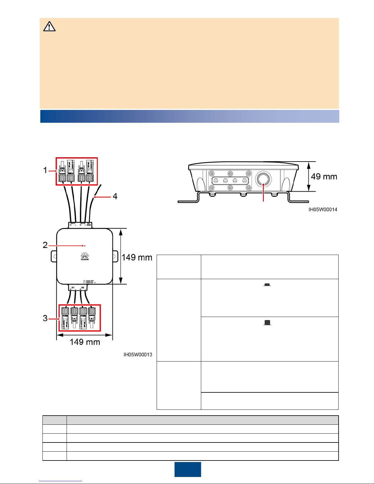
The SmartPSB2000L smart PV safety box (safety box for short) is a key component that implements rapid
shutdown and module monitoring for Huawei SUN2000P-375W smart PV optimizers. The safety box is easy to
install, operate, and maintain.
Shutdown button
NOTICE
Rapid shutdown means that the power generation system consisting
of optimizers, smart PV safety boxes, and inverters decreases the DC
voltage to the safe voltage range (≤ 30 V) within the specified period
(≤ 30s).
No.
Description
1
Two routes of output terminals, cable length (including terminals) 250 mm
2
An LED indicator showing the running status of the safety box
3
Two routes of input terminals, cable length (including terminals) 150 mm
4
RS485 communication, PE, and 12 V power cables, 340 mm long
Copyright © Huawei Technologies Co., Ltd. 2018. All rights
reserved.
Prerequisites
An optimizer is installed for each PV module, and
the rapid shutdown function of the safety box is
enabled.
Trigger by
button press
If the shutdown button (
) is pressed, the safety
box enters the rapid shutdown state. The LED
indicator is steady red, and the inverter turns off the
AC output. This product cannot be used as a
substitute for the emergency stop switch.
If the shutdown button (
) is released, the safety
box exits the rapid shutdown state. The LED
indicator is steady red within 10 minutes. The output
voltages of the optimizer and inverter are restored
10 minutes later. The LED indicator of the safety box
changes from steady red to steady green.
Trigger by
power failure
If the AC power fails, the safety enters the rapid
shutdown state. The inverter and optimizer stop
output and communication. The LED indicators of
the safety box and inverter are off.
If the AC power resumes, the inverter, optimizer,
and safety box restore to the normal state.
Page 3
2
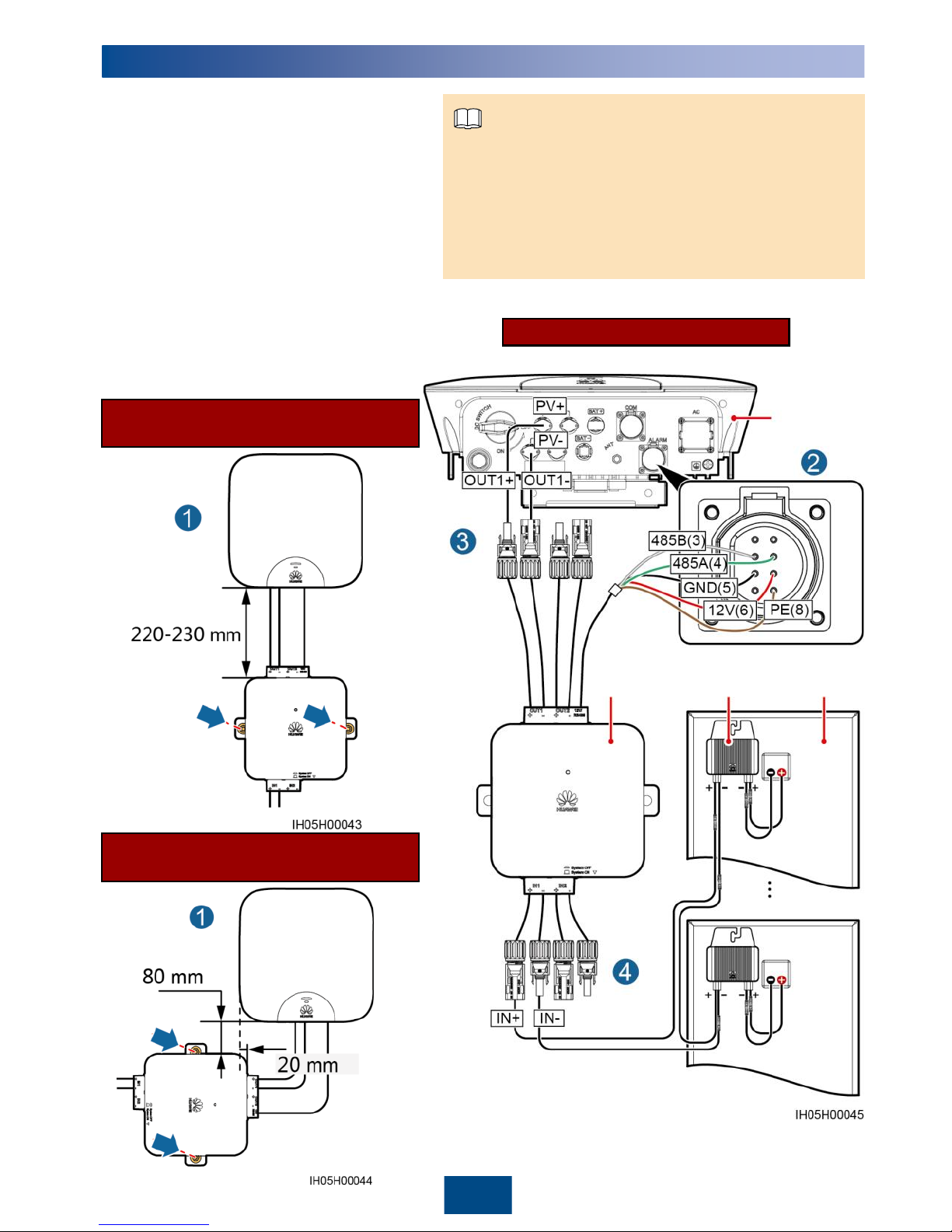
Installation Mode 2
(Recommended Distance)
2
Installation and Cable Connections
Wiring Diagram
1. Each input of the safety box supports serial connection of
up to 15 optimizers, and the stringvoltage should be less
than 600 V DC.
2. After the cord end terminal is removed, the PE cable of the
safety box and the communication PE cable of the power
meter can be connected together to the communication
terminal (pin 8) of the inverter.
NOTE
1. Install the safety box under or on a side of an
inverter with the delivered M6x60 expansion
bolts. It is recommended that an M8 drill bit
be used to drill holes. The torque should be
4.5–5.5 N·m.
2. Connect the RS485 communications, PE,
and 12 V power cables from the safety box to
the corresponding port on the inverter.
3. Connect the output terminals of the safety
box to the DC input ports of the inverter (one
route is used as an example in the right
figure).
4. Connect the input terminals of the safety box
to the output ports of the optimizer string
(one route is used as an example in the right
figure).
Inverter
Safety box Optimizer PV module
Installation Mode 1
(Recommended Distance)
Page 4
3
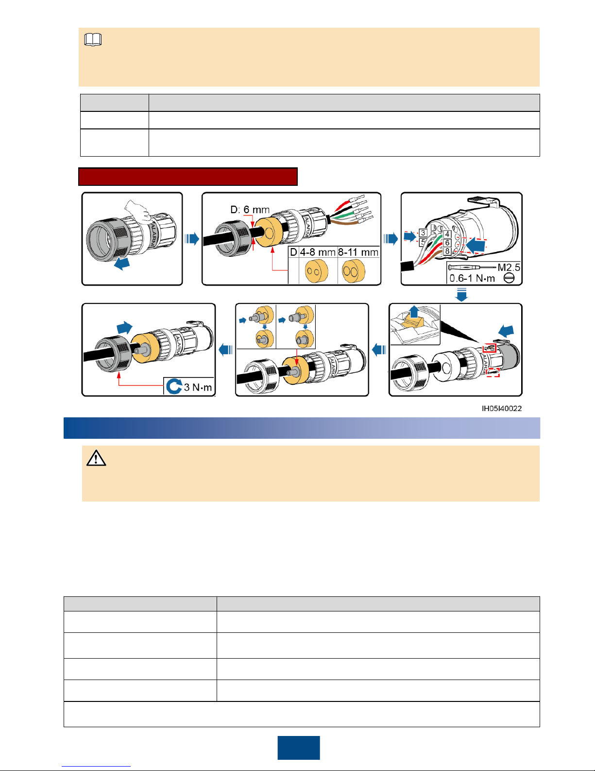
Port Inverter Model
COM SUN2000L-3KTL-CN, SUN2000L-4KTL-CN, SUN2000L-5KTL-CN
ALARM
SUN2000L-2KTL, SUN2000L-3KTL, SUN2000L-3.68KTL, SUN2000L-4KTL, SUN2000L-
4.6KTL, SUN2000L-5KTL
Depending on the inverter model, the RS485 communications, PE, and 12 V power cables need to be
connected to the COM or ALARM port of the inverter. The pins are wired in the same way.
COM or ALARM Terminal Connection
1. Switch on the AC circuit breaker between the inverter and the power grid (the AC voltage of the power grid
should be in the range allowed by the inverter).
2. Turn the DC switch at the bottom of the inverter to the ON position.
3. Observe the LED indicator on the safety box. The status change sequence should be: blinking green at long
intervals> blinking green at short intervals. If the LED indicator is abnormal, check whether cables are
connected correctly and securely.
3
Powering On the Safety Box
NOTE
LED Status Description
Blinking green at long intervals
Power on self test.
Blinking green at short intervals
Communicating with the inverter properly and not communicating with the
optimizer.
Steady green
Communicating with the inverter and optimizer properly.
Steady red
Shutdown.
Blinking green at long intervals: on for 1s and then off for
1s
Blinking green at short intervals: on for 0.2s and then off for 0.2s
1. Check whether all cables to the safety box are properly connected.
2. Input and output terminals are correctly paired, and no crossover exists.
NOTICE
Page 5
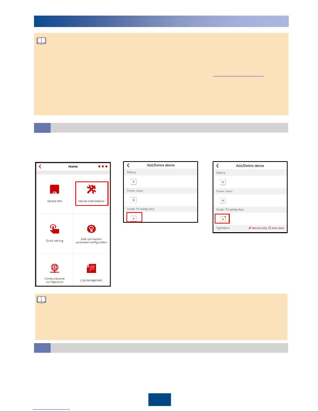
Adding the Safety Box
4.1
1. Log in to the app and access
the Operation console
screen.
2. Choose Device maintenance >
Add/Delete device and tap Smart
PV safety box.
4
1. The near-end FusionHomeapp (app for short) is a mobile phone app that locally communicates with the
inverter over WiFi for alarm query, parameter configuration, routine maintenance, and commissioning.
2. Requirements for the mobile phone operating system: Android 4.4 or later, iOS 8.0 or later.
3. For details about app connection and login, see the inverter manual available onsite. User interfaces (UIs) on
the Android system are used as an example. The actual UIs prevail.Log in to http://solar.huawei.comand
chooseSERVICES > Download Center to obtain the latest document.
4. The inverter and safety box cannot perform any commissioning tasks when the AC power is disconnected.
5. The inverter software version matching the smart PV safety box must be V100R001C00SPC317 or later. The
app version must be 2.1.11.302 or later.
6. The app screen snapshots provided in this document correspond to FusionHome2.1.11.303. The figures are
for reference only.
4
FusionHome App
NOTE
NOTE
1. If the safety box icon is green, the safety box is running properly.
2. If the safety box icon is yellow, the safety box is in standby state.
3. If the safety box icon is gray, the safety box is abnormal in communication. Check whether its cable connections
and communications parameters are correct.
4. If the safety box icon is red, the safety box is in rapid shutdown check state.
3. After the safety box is added
successfully, the safety box icon
is displayed.
Adding Optimizers
4.2
Automatic search: Automatically search for optimizer SNs and string numbers. You need to manually modify
device names and locations.
Manual configuration: Manually configure the SNs, string numbers, device names, and locations of optimizers.
Add optimizers by automatic search or manual configuration.
Page 6
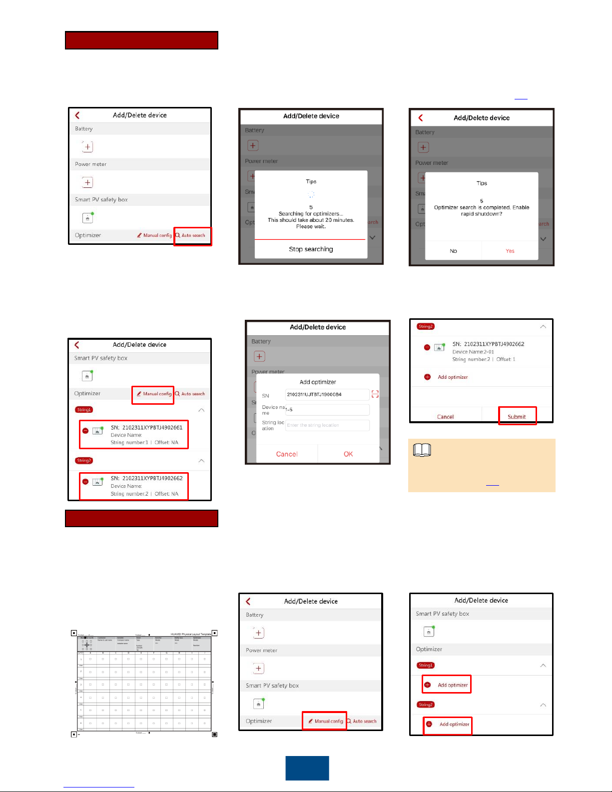
2. The optimizer search takes about 20
minutes. If you tap Stop searching,
the information of the optimizers
already found will be saved.
3. After the search is canceled or
completed, the screen for
enabling Rapid shutdown is
displayed (see section 4.3).
5
1. Tap Auto search.
Manual Configuration
4. If you tap No in the previous step,
the screen for adding devices is
displayed.Tap Manual configand
tap the optimizer to modify optimizer
information.
5. Modify optimizer information.
2. Tap Manual config.
Automatic Search
3. By default, two strings are
configured. Tap Add optimizer.
1. When installing optimizers,
remove the SN bar codes
and attach them to their
respective positions on the
same layout form. For details,
see the usage instructions on
the rear of the form.
For details about the optimizer
icon, see section 5.1.
NOTE
6. Tap Submit to begin optimizer
search (step 5 in Manual
Configuration).
Page 7
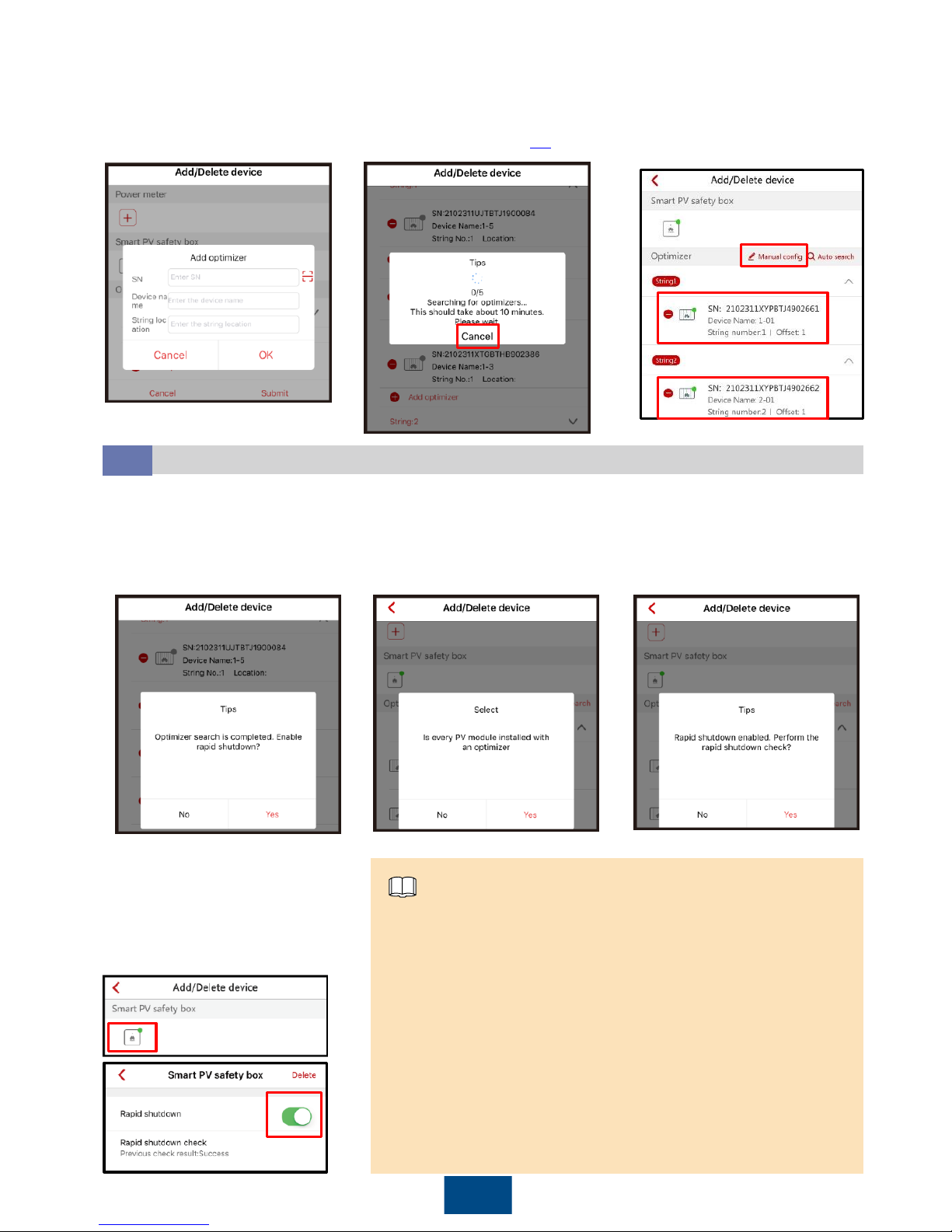
6
Performing Rapid Shutdown Check
4.3
4. Enter optimizer information to
add all optimizers in sequence
by scanning their QR codes or
manually entering their SNs.
1. After optimizer search is
complete, the screen for enabling
Rapid shutdown is displayed
automatically.
1. You need to enable Rapid shutdownand start Rapid shutdown
check only if an optimizer is installed for each PV module. To support
the rapid shutdown function, enable Rapid shutdown (disabled by
default) for the safety box. If Rapid shutdownis disabled, the rapid
shutdown function is ineffective.
2. If optimizers are installed only for certain PV modules, the rapid
shutdown function is ineffective no matter whether you enable Rapid
shutdownor press the shutdown button.
3. Rapid shutdown checkis displayed only if Rapid shutdown is
enabled.
4.If optional configuration of optimizers is adopted, the rapid
shutdown check fails and the rapid shutdown function is
ineffective.
NOTE
6. If you tap Cancel to stop the
search, the entered optimizer
information is saved.You can tap
Manual config to add a new
optimizer or tap the optimizer to
modify optimizer information.
5. Tap OK. Automatic search
for optimizers begins and will last
about 10 minutes. After the search
is completed, the screen for
enabling Rapid shutdown is
displayed (see section 4.3).
4. If you did not enable Rapid
shutdown or perform rapid
shutdown check, you can still tap
the shutdown box icon to access
the screen for enabling Rapid
shutdownor performing rapid
shutdown check.
3. After Rapid shutdown is enabled,
a dialog box for performing rapid
shutdown check is automatically
displayed. Even if you tap No, the
rapid shutdown function is still
valid.
2. If you enable Rapid shutdown,
check whether an optimizer is
installed for each PV module.
If you tap No, the screen for
adding devices is displayed.
Page 8
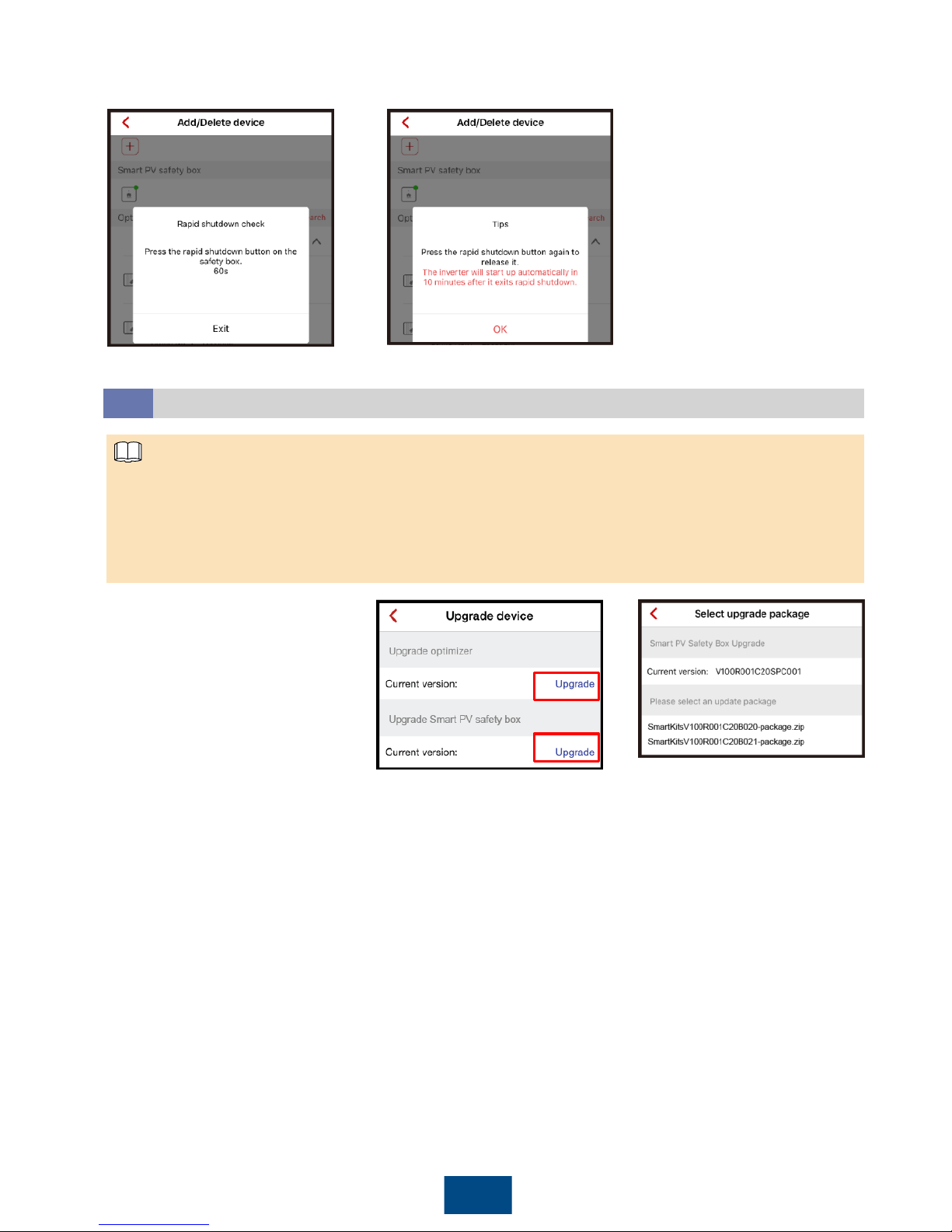
7
(Optional) Upgrading the Software
4.4
1. Obtain the upgrade file from your dealer or Huawei engineers.
2. On the Android system, you can copy the upgrade file to the mobile phone. The upgrade file name extension
must be .zip, the file can be flexibly stored, and Manually select is supported.
3. On the iOS system, you can import the upgrade file to the app through a mailbox. The upgrade file name
extension must be .zip, and Manually select is not supported.
4. Upgrading the safety box or optimizer lasts for 10–20 minutes.
NOTE
2. Select the appropriate upgrade
package and finish the upgrade.
1. Choose Upgrade device on the
Operation consolescreen to
upgrade the optimizer or smart PV
safety box.
5. Press the Rapid shutdown
button within 60s as prompted.
If you tap Exit, the screen for
adding devices is displayed.
6. After rapid shutdown succeeds,
release the button as prompted.
The inverter will start in 10 minutes.
Page 9
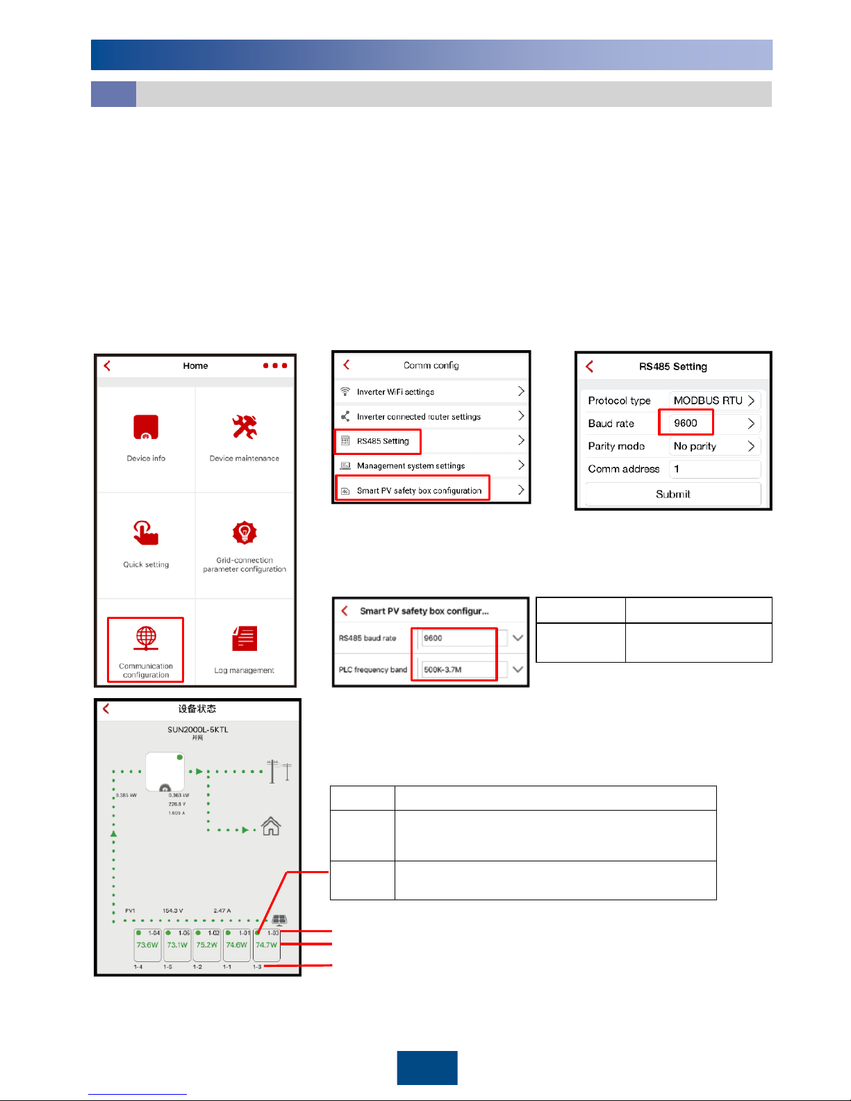
1. If the LED indicator of the safety box is blinking green slowly (at 0.5 Hz), check whether its communications
cable is connected correctly or check its communications parameter settings. The same RS485 baud rate should
be set for the safety box, inverter, power meter, and battery that implement RS485 communication.
2. If setting safety box communications parameters fails, set the inverter baud rate to 9600 bps, and then perform
three cycles of press + release operations on the shutdown button within 1 minute. Then, the RS485
communications parameters of the safety box are restored to default values, and the LED indicator blinks red
and green (red for 0.25s, green for 0.25s, lasts for 20s).
3. If the message "The PLC frequency band is congested. Switch the frequency band." is displayed on the app,
change the PLC frequency band. The change process takes about 3 minutes. Do not power off the safety box.
Communication Fault
5.1
4.3
5
Maintenance
8
4. After communication is successful, the optimizer
information is displayed in Device info on the
Operation consolescreen.
1. Log in to the app, access the
Operation consolescreen,
and then choose Comm
config.
2. Choose Smart PV safety box
configuration. Then set RS485
baud rate and PLC frequency band.
3. Choose RS485 Setting, and
then set the Baud rate for the
inverter.
Baud rate
9600 (default), 19200
Frequency
band
500K
-3.7M(default),
1.5M
-4.7M
Optimizer output power
Optimizer position
Green
The optimizer is running properly.
Gray
The optimizer runs abnormally. Check whether its SN
and position information are correct.
Then search
the
optimizer again.
Red
The optimizer is faulty. Troubleshoot according to the
optimizer manual.
Optimizer alias
Page 10
9
Replacing the Safety Box
5.2
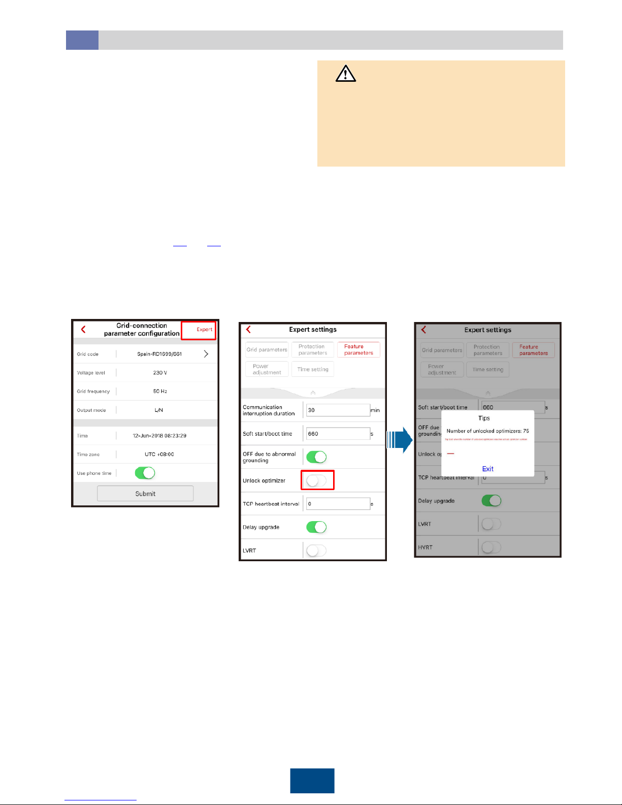
(1) Log in to the app and access the
Operation Consolescreen.
Choose Grid-connect config>
Expert.
(2) Choose Feature parameters and
enable Unlock optimizer.Unlock
optimizer exits automatically after
unlocking is complete.
NOTICE
Replace the safety box if any of the following faults
occurs.
• The appearance is seriously damaged.
• Cables are seriously damaged.
• The LED indicator status does not match the actual
status.
• The key button is damaged and fails.
• The key button is not damaged, but the shutdown
function fails.
• Obtain the user's consent before replacing the safety
box, as the inverter may have no output during the
replacement.
• The safety box can be replaced only 30 seconds after
you turn off the DC input switch on the inverter and
the switch on the AC output loop.
1. Turn off the DC input switch on the inverter and the switch on the AC output loop.
2. Remove the old safety box.
3. Install a new safety box, as shown in the chapter 2.
4. Turn on the DC input switch on the inverter and the switch on the AC output loop.
5. Log in to the FusionHomeapp, unlock optimizers (as shown in the following figure), and then add the optimizers
again (see sections 4.2and 4.3). You need to perform this step when replacing the safety box, optimizer, or
inverter.
Page 11
10
6
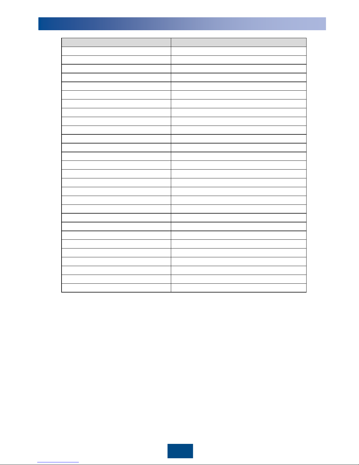
Technical Specifications
Item
Specifications
Maximum input voltage
600 V
DC
Maximum input current
15 A
Maximum short
-circuit current
15 A
Maximum number of inputs
2
Maximum output voltage
600 V
DC
Maximum output current
15 A
Maximum number of outputs
2
DC power supply
12 V
DC
Protection level
IP65
Power consumption
<
3 W
Noise
<
35 dB
Cooling mode
Natural cooling
Display
LED
Installation mode
Wall
-mounted
Dimensions
149 mm x 149 mm x 49 mm
(excluding cables)
Weight
0.8 kg (
including cables)
Input and output terminals
H4 x 2/H4 x 2
Operating temperature
–
30°C to +55°C
Operating humidity
5
%–95% RH
Operating altitude
0
–4000 m (≥ 2000 m: 1
°
C/200 m derating)
Storage temperature
–
40°C to +70°C
Storage humidity
5%
–95% RH
Networking mode
PLC, RS485
Safety compliance
IEC62109
Electromagnetic compatibility (EMC)
IEC61000
-6-2, IEC61000-6-3
Mean time between failures (MTBF)
500,000 hours
Design life
25 years (excluding field replaceable parts)
Environmental protection
RoHS
Page 12

Huawei Technologies Co., Ltd.
Huawei Industrial Base, Bantian, Longgang
Shenzhen 518129 People's Republic of China
www.huawei.com
 Loading...