


SmartLogger2000
User Manual
Date 2016-06-20
HUAWEI TECHNOLOGIES CO., LTD.

Copyright © Huawei Technologies Co., Lt d. 2016 . All right s reserv ed.
No part of this document may be reproduced or transmitted in any form or by any means without prior
written consent of Huawei Technologies Co., Ltd.
Trademarks and Permissions
and other Huawei trademarks are trademarks of Huawei Technologies Co., Ltd.
All other trademarks and trade names mentioned in this document are the property of their respective
holders.
Notice
The purchased products, services and features are stipulated by the contract made between Huawei and
the customer. All or part of the products, services and features described in this document may not be
within the purchase scope or the usage scope. Unless otherwise specified in the contract, all statements,
information, and recommendations in this document are provided "AS IS" without warranties, guarantees or
representations of any kind, either express or implied.
The information in this document is subject to change without notice. Every effort has been made in the
preparation of this document to ensure accuracy of the contents, but all statements, information, and
recommendations in this document do not constitute a warranty of any kind, express or implied.
Huawei Technologies Co., Ltd.
Address: Huawei Industrial Base
Bantian, Longgang
Shenzhen 518129
People's Republic of China
Website: http://www.huawei.com
Email: support@huawei.com
(2016-06-20) Huawei Proprietary and Confidential
Copyright © Huawei Technologies Co., Ltd.
i
SmartLogger2000
User Manual About This Document
About This Document
Overview
This document introduces the SmartLogger2000 (SmartLogger for short) in terms of
installation, cable connections, system operation and maintenance, and troubleshooting.
Readers should understand the SmartLogger features, functions, and safety precautions
provided in this document before installing and operating the SmartLogger.
The figures provided in this document are for reference only. The actual product appearance
prevails.
You can print the document based on your requirements. Store the paper copy properly for
future use. You can log in to http://support.huawei.com/carrier/, click Product Support, and
search for SmartLogger to view and obtain the latest user manual.
Intended Audience
This document is intended for photovoltaic (PV) plant operators and qualified electrical
technical personnel.
Symbol Conventions
The symbols that may be found in this document are defined as follows.
Symbol Description
Indicates an imminently hazardous situation which, if not
avoided, will result in death or serious injury.
Indicates a potentially hazardous situation which, if not
avoided, could result in death or serious injury.
Indicates a potentially hazardous situation which, if not
avoided, may result in minor or moderate injury.
Indicates a potentially hazardous situation which, if not
avoided, could result in equipment damage, data loss,
performance deterioration, or unanticipated results.
NOTICE is used to address practices not related to personal
(2016-06-20) Huawei Proprietary and Confidential
Copyright © Huawei Technologies Co., Ltd.
ii

SmartLogger2000
User Manual About This Document
Symbol Description
injury.
Change History
Changes between document issues are cumulative. The latest document issue contains all the
changes made in earlier issues.
Calls attention to important information, best practices and
tips.
NOTE is used to address information not related to personal
injury, equipment damage, and environment deterioration.
(2016-06-20) Huawei Proprietary and Confidential
Copyright © Huawei Technologies Co., Ltd.
iii

SmartLogger2000
User Manual Contents
Contents
About This Document .................................................................................................................... ii
1 Safety Precautions ......................................................................................................................... 1
2 Overview ......................................................................................................................................... 3
2.1 Overview ...................................................................................................................................................................... 3
2.2 Appearance ................................................................................................................................................................... 6
2.3 Nameplate Description ............................................................................................................................................... 10
2.4 Typical Networking Scenarios .................................................................................................................................... 11
2.5 System Wiring Diagram.............................................................................................................................................. 14
3 Installation.................................................................................................................................... 22
3.1 Checking Before Installation ...................................................................................................................................... 22
3.2 Preparing Tools ........................................................................................................................................................... 23
3.3 Determining the Installation Position ......................................................................................................................... 25
3.4 Installing the SmartLogger ......................................................................................................................................... 27
3.4.1 Mounting the SmartLogger on a Wall ...................................................................................................................... 27
3.4.2 Mounting the SmartLogger Along a Guide Rail ...................................................................................................... 31
3.5 Installing the RS485 signal SPD ................................................................................................................................. 34
4 Connecting Cables ...................................................................................................................... 36
4.1 Connection Description .............................................................................................................................................. 37
4.2 Connecting the PE Cable ............................................................................................................................................ 37
4.2.1 Connecting the PE Cable for the SmartLogger ........................................................................................................ 37
4.2.2 Connecting the PE Cable for the RS485 Signal SPD .............................................................................................. 39
4.3 Connecting the RS485 signal SPD ............................................................................................................................. 40
4.4 Connecting Inverters ................................................................................................................................................... 44
4.4.1 Connecting the SUN2000 ........................................................................................................................................ 44
4.4.2 Connecting the SUN8000 ........................................................................................................................................ 52
4.4.3 Connecting Multiple Inverters to the SmartLogger ................................................................................................. 54
4.5 Connecting an EMI ..................................................................................................................................................... 56
4.6 Connecting a Power Meter ......................................................................................................................................... 58
4.7 Connecting the Box-type Transformer ........................................................................................................................ 59
4.8 Connecting a PID Module .......................................................................................................................................... 61
4.9 Connecting a Ripple Control Receiver ....................................................................................................................... 62
(2016-06-20) Huawei Proprietary and Confidential
Copyright © Huawei Technologies Co., Ltd.
iv

SmartLogger2000
User Manual Contents
4.10 Connecting an Ethernet Network Cable ................................................................................................................... 65
4.11 Connecting Optical Fibers ........................................................................................................................................ 66
5 System Operation ........................................................................................................................ 69
5.1 Checking Before Power-On ........................................................................................................................................ 69
5.2 Powering On the System............................................................................................................................................. 70
6 User Interface ............................................................................................................................... 72
6.1 USB Flash Drive Operations ...................................................................................................................................... 72
6.1.1 Exporting Data ......................................................................................................................................................... 72
6.1.2 Exporting All Files ................................................................................................................................................... 73
6.1.3 Importing All Files ................................................................................................................................................... 74
6.1.4 Upgrading the Application ....................................................................................................................................... 76
6.1.5 Upgrading the BSP .................................................................................................................................................. 77
6.2 NMS Operations ......................................................................................................................................................... 78
6.3 APP Operations ........................................................................................................................................................... 78
7 Maintenance ................................................................................................................................. 79
7.1 Daily Maintenance ...................................................................................................................................................... 79
7.2 Troubleshooting .......................................................................................................................................................... 79
7.3 Alarms ......................................................................................................................................................................... 81
8 Disposing of the SmartLogger .................................................................................................. 84
9 Certification Declaration ........................................................................................................... 85
9.1 CE ............................................................................................................................................................................... 85
9.2 FCC ............................................................................................................................................................................. 85
10 Technical Specifications .......................................................................................................... 86
A Product User Lists ...................................................................................................................... 88
B Acronyms and Abbreviations .................................................................................................. 89
(2016-06-20) Huawei Proprietary and Confidential
Copyright © Huawei Technologies Co., Ltd.
v
SmartLogger2000
User Manual 1 Safety Precautions
1 Safety Precautions
Read the safety precautions carefully. Otherwise, human injury and equipment damage may
occur.
Personnel Requirements
Only qualified and trained electrical technicians are allowed to install and operate the
SmartLogger.
Operation personnel should understand the composition and working principles of the
PV grid-tied power generating system and local regulations.
Read this document thoroughly before operations. Huawei shall not be liable for any
consequence caused by violation of the storage, transportation, installation, and operation
regulations specified in this document.
Identification Protection
The signs on the SmartLogger shell specify important information about secure
operations. Do not damage the signs.
The nameplate attached to the bottom of the SmartLogger lists the SmartLogger
parameters. Do not damage the nameplate.
Installation
Before installation, read this document carefully. Huawei shall not be liable for any
consequence caused by violation of the regulations specified in this document.
Before installing the SmartLogger, ensure that it is not connected or energized.
Install the SmartLogger in well-ventilated environments to ensure system performance.
(2016-06-20) Huawei Proprietary and Confidential
Copyright © Huawei Technologies Co., Ltd.
1

SmartLogger2000
User Manual 1 Safety Precautions
Ensure that the heat dissipation holes of the SmartLogger are not blocked.
Do not move the components inside the shelf except for the wiring terminals at the
bottom.
Install the SmartLogger in a dedicated area.
Operation
Strictly comply with the safety precautions in this document and associated documents to
operate the SmartLogger.
When operating the SmartLogger, follow local laws and regulations.
Maintenance and Replacement
A faulty SmartLogger requires overall maintenance. Contact the dealer if any fault
occurs in the SmartLogger shelf.
Maintain the SmartLogger after you get familiar with this document and tools and testing
equipment are available.
When maintaining the SmartLogger, wear ESD gloves and comply with ESD
precautions.
The device has multiple inputs. Switch off all inputs before the maintenance.
(2016-06-20) Huawei Proprietary and Confidential
Copyright © Huawei Technologies Co., Ltd.
2

SmartLogger2000
User Manual 2 Overview
2 Overview
About This Chapter
2.1 Overview
2.2 Appearance
2.3 Nameplate Description
2.4 Typical Networking Scenarios
2.5 System Wiring Diagram
2.1 Overview
Function
The SmartLogger is a highly integrated device dedicated for monitoring and managing the PV
power system. It converges ports, converts protocols, collects and stores data, and centrally
monitors and maintains devices in the PV power system.
Features
The SmartLogger provides the following features:
Wide application
− Industrial-grade application, wide temperature range: –40°C to +60°C
− High altitude: applicable at an altitude of 4000 m
Various communications modes
− Bluetooth
Has a built-in Bluetooth module through which the SUN2000 APP (APP for short)
connects to the SmartLogger for parameter configuration and device maintenance.
The SmartLogger Bluetooth is named as LOG+the last eight figures of the ESN
of the SmartLogger.
− Optical fiber ring switch
Provides two 100M Ethernet optical ports that support RSTP and STP to implement
fiber ring networking. If RSTP is used, fiber ring protection can be completed
(2016-06-20) Huawei Proprietary and Confidential
Copyright © Huawei Technologies Co., Ltd.
3

SmartLogger2000
User Manual 2 Overview
within 10 seconds. If STP is used, fiber ring protection can be completed within 60
seconds.
− PLC
Has a built-in PLC CCO module through which southbound devices connect to the
SmartLogger over AC power cables.
− Ethernet electrical port
Provides two 10/100M Ethernet electrical ports that can be used as southbound
ports to connect to southbound devices or used as northbound ports to connect to an
NMS.
A southbound port connects to a downstream device for collecting data and setting parameters.
Southbound devices include the inverter, environmental monitoring instrument (EMI), power meter,
box-type transformer, and PID module.
A northbound port connects to an upstream NMS for uploading data.
− RS485
Supports six RS485 routes and access of devices that use Modbus-RTU, IEC103,
and DL/T645.
Graphical data
− In addition to displaying the electricity yield and real-time monitoring information
in graphic and text format, the embedded WebUI can also display performance data
of power stations and devices in tables or curves.
− The APP displays the electricity yield and real-time monitoring information in
graphic and text format.
Centralized monitoring
− Manages a maximum of 200 devices in centralized mode and supports the access of
up to 80 inverters.
− Allows you to monitor and manage the PV power system on the embedded WebUI,
for example, viewing real-time information about power stations, devices, and
faults, setting device parameters, and maintaining devices in remote mode.
− Allows you to monitor the devices in the PV power system on the APP in real time,
such as viewing information about power stations, devices, products, and faults,
setting device parameters, and maintaining devices.
Easy maintenance
− Allows users to upgrade the firmware of the SmartLogger and export data by using
a USB flash drive.
− Allows you to upgrade the firmware of the SmartLogger, inverter, AC combiner box,
PLC module, and PID module, and export logs and data over the embedded WebUI.
− Allows you to manage the devices connecting to the SmartLogger and classify
alarms over the APP.
Intelligent management
− Automatically searches for and accesses Huawei inverters, AC combiner boxes,
PLC modules, and PID modules. If you import a parameter configuration table, the
SmartLogger can access third-party devices that support Modbus-RTU and IEC103.
− Automatically assigns RS485 addresses to the connected Huawei inverters, AC
combiner boxes, and PID modules, and allows for RS485 address adjustment based
on ESNs to facilitate remote configuration and maintenance.
− Supports remote configuration of inverter parameters over the embedded WebUI
and synchronizes the parameters from one inverter to other inverters in batches.
(2016-06-20) Huawei Proprietary and Confidential
Copyright © Huawei Technologies Co., Ltd.
4
SmartLogger2000
User Manual 2 Overview
− Automatically collects the data generated during the communication disconnection
from the inverter or manually collects the data over the embedded WebUI after the
connection resumes.
Remote maintenance
− Simultaneously accesses multiple NMSs (including Huawei NetEco and third-party
NMSs) that support Modbus-TCP, IEC103, and IEC104. Huawei NetEco features
centralized O&M, big data analysis, intelligent diagnosis, and mobile O&M.
− Supports connection to a third-party NMS over File Transfer Protocol (FTP).
− Sends electricity yield and alarms to users by emails.
Grid scheduling
− The SmartLogger supports various power grid scheduling modes and therefore can
meet the requirements of power grid companies in different countries.
− Implements rapid active power control and reactive power compensation for all the
inverters connecting to the SmartLogger.
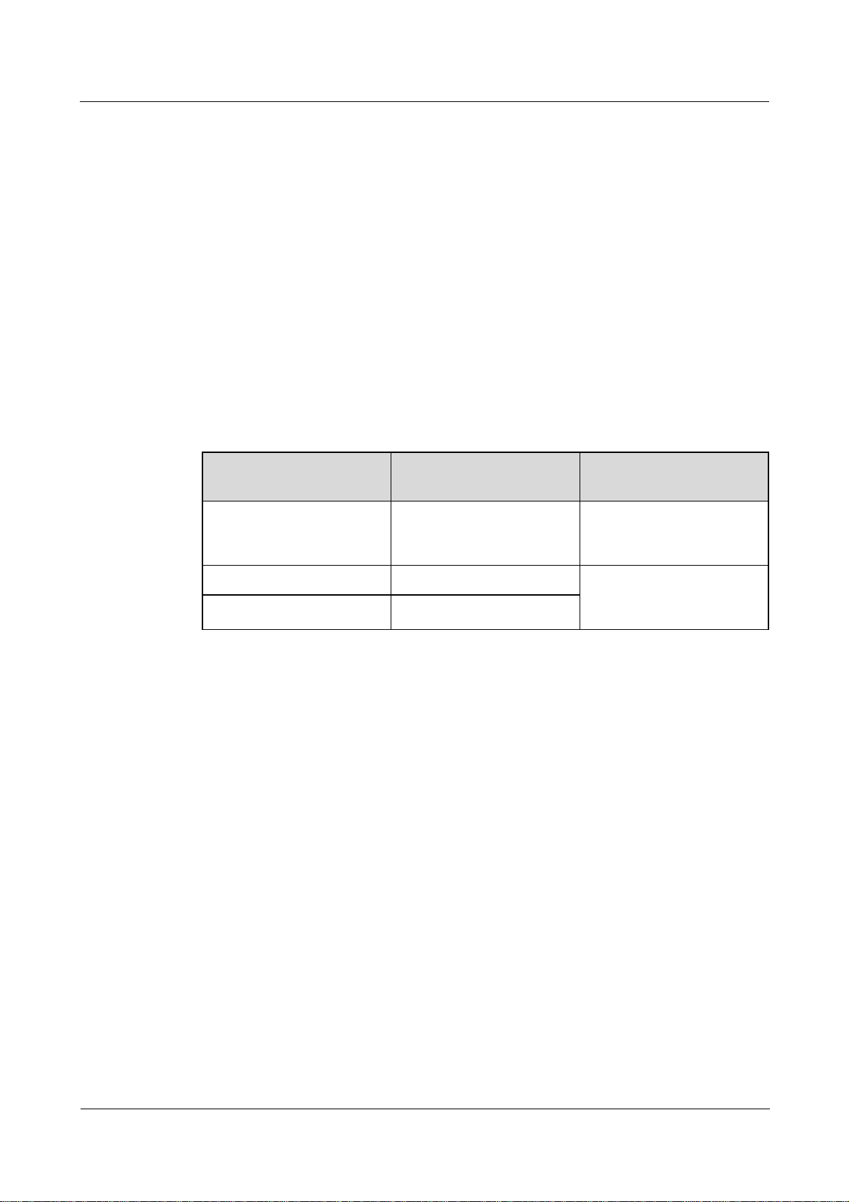
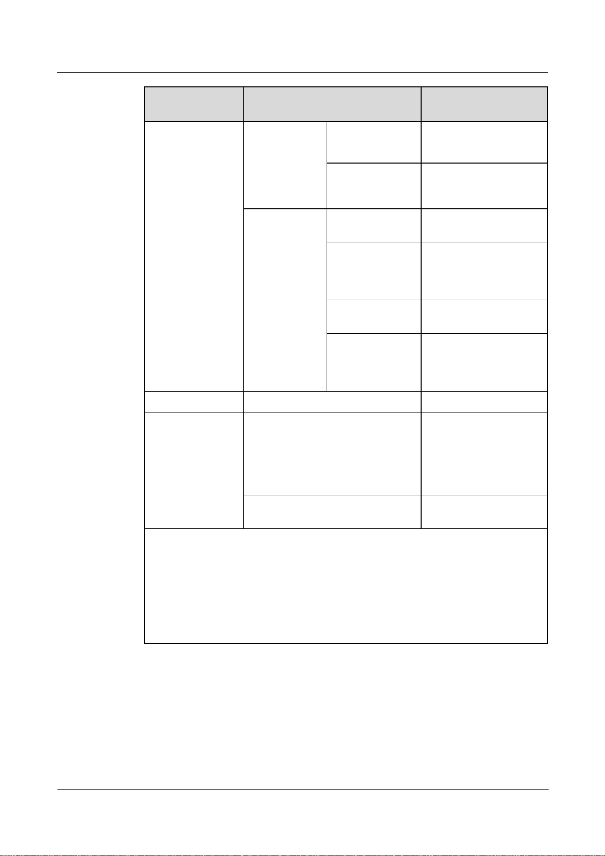
Model Description
Model PLC Module
Remarks
Configured?
SmartLogger2000-10 Yes The built-in Bluetooth
module supports only
Android APP.
SmartLogger2000-10-B Yes The built-in Bluetooth
module supports both
SmartLogger2000-11-B No
Android APP and IOS APP.
(2016-06-20) Huawei Proprietary and Confidential
Copyright © Huawei Technologies Co., Ltd.
5
SmartLogger2000
User Manual 2 Overview
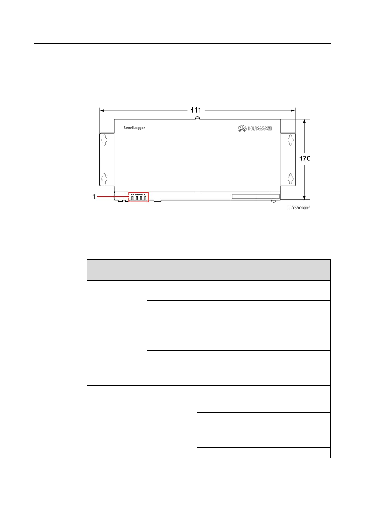
2.2 Appearance
Front View of the Shell
Figure 2-1 SmartLogger front view (unit: mm)
(1) Indicators
Table 2-1 Description of the LED indicators (from left to right)
Indicator (Silk
Screen)
RUN indicator Green off The SmartLogger is not
Alarm/maintenance
indicator (ALM)
Status Meaning
powered on.
Blinking green at short intervals (on
for 0.125s and then off for 0.125s)
Blinking green at long intervals (on
for 1s and then off for 1s)
Alarm status Red off The SmartLogger and the
a
The SmartLogger and the
NMS (the NetEco or a
third-party NMS) are not
connected or the
communication between
them is interrupted.
The SmartLogger properly
communicates with the
NMS (NetEco or a
third-party NMS).
devices accessing it do not
generate any alarm.
Blinking red at
long intervals (on
for 1s and then off
for 4s)
Blinking red at The SmartLogger or the
(2016-06-20) Huawei Proprietary and Confidential
Copyright © Huawei Technologies Co., Ltd.
The SmartLogger or the
devices accessing it
generate warnings.
6
SmartLogger2000
User Manual 2 Overview
Indicator (Silk
Screen)
Status Meaning
short intervals (on
for 0.5s and then
devices accessing it
generate minor alarms.
off for 0.5s)
Steady red The SmartLogger or the
devices accessing it
generate major alarms.
Maintenance
status
Green off No local maintenance is
underway
Blinking green at
long intervals (on
Local maintenance is in
progress.
for 1s and then off
for 1s)
Steady green Local maintenance
succeeds.
Blinking green at
Local maintenance fails.
short intervals (on
for 0.125s and then
off for 0.125s)
b
.
3G/4G indicator - Reserved.
Bluetooth indicator
(BLE)
Green off You have not logged in to
the APP or login failed.
The SmartLogger is not
connected to the APP or
Blinking green at long intervals (on
for 1s and then off for 1s)
the communication has
been interrupted
You have successfully
logged in to the APP.
c
.
a: If an alarm and local maintenance happen concurrently, the alarm/maintenance indicator
shows the near-end maintenance state first. After the USB flash drive is removed, the
indicator shows the alarm state.
b: Local maintenance refers to operations performed by connecting a USB flash drive to the
SmartLogger USB port, such as full data import and export using a USB flash drive.
c: After the communication between the SmartLogger and the APP fails, the disconnection
is normal if the green indicator goes off immediately, and is abnormal if the indicator goes
off after blinking slowly for 30s.
(2016-06-20) Huawei Proprietary and Confidential
Copyright © Huawei Technologies Co., Ltd.
7
SmartLogger2000
User Manual 2 Overview
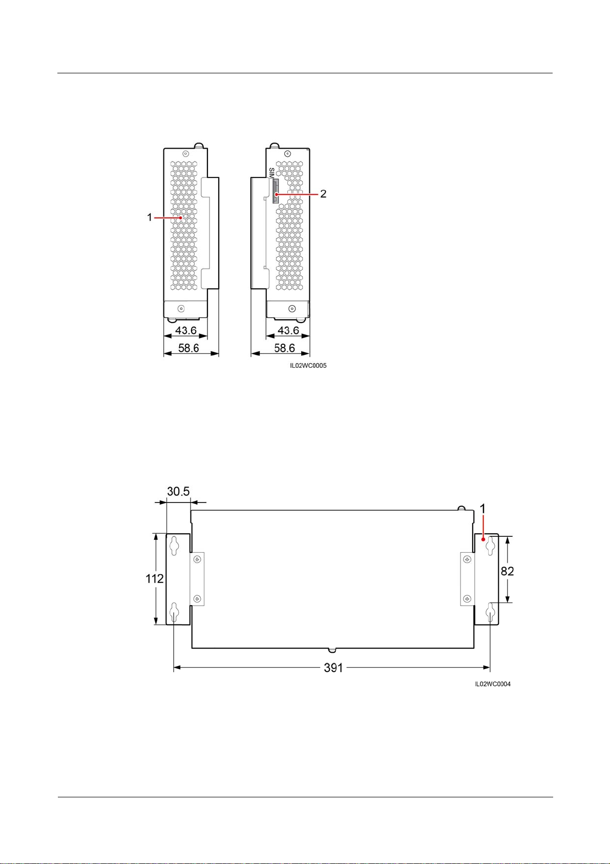
Side View of the Shell
Figure 2-2 SmartLogger side view (unit: mm)
(1) Heat dissipation hole (2) SIM card slot (reserved)
Rear View of the Shell
Figure 2-3 SmartLogger rear view (unit: mm)
(1) Wall-mounting ears
(2016-06-20) Huawei Proprietary and Confidential
Copyright © Huawei Technologies Co., Ltd.
8
SmartLogger2000
User Manual 2 Overview
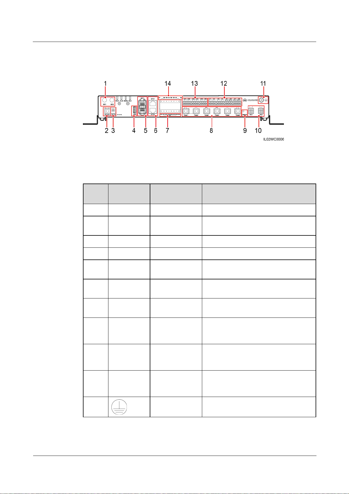
Bottom of the Shell
Figure 2-4 Bottom view of the SmartLogger
Table 2-2 describes the functions of ports on the SmartLogger.
Table 2-2 Port description
No. Port (Silk
Function Description
Screen)
1 RF1, RF2 Reserved Reserved.
2 12V OUT 12 V DC output Provides 12 V DC power supply with a
maximum current of 100 mA.
3 12V IN 12 V DC input Connects to a power adapter.
4 USB USB port Connects a USB flash drive.
5 SFP1, SFP2 Ethernet optical
port
6 ETH1, ETH2 Ethernet electrical
port
7 DO Digital parameter
Connects to an ATB or another cascaded
SmartLogger.
Connects to an Ethernet switch, router,
POE module, or PC.
Relay output.
output
8 COM1–COM6 RS485
communication
Six RS485 ports that can be connected to
devices such as the inverter, box-type
transformer, power meter, or EMI.
9 Default Default key Resets and restarts the Bluetooth module or
resets the SmartLogger IP address to the
default IP address
d
.
10 AC1, AC2 AC power cable
ports
Connects to A, B, and C three-phase inputs
for power line communication (PLC) with
the inverter.
11
(2016-06-20) Huawei Proprietary and Confidential
Copyright © Huawei Technologies Co., Ltd.
External
grounding
-
9
SmartLogger2000
User Manual 2 Overview
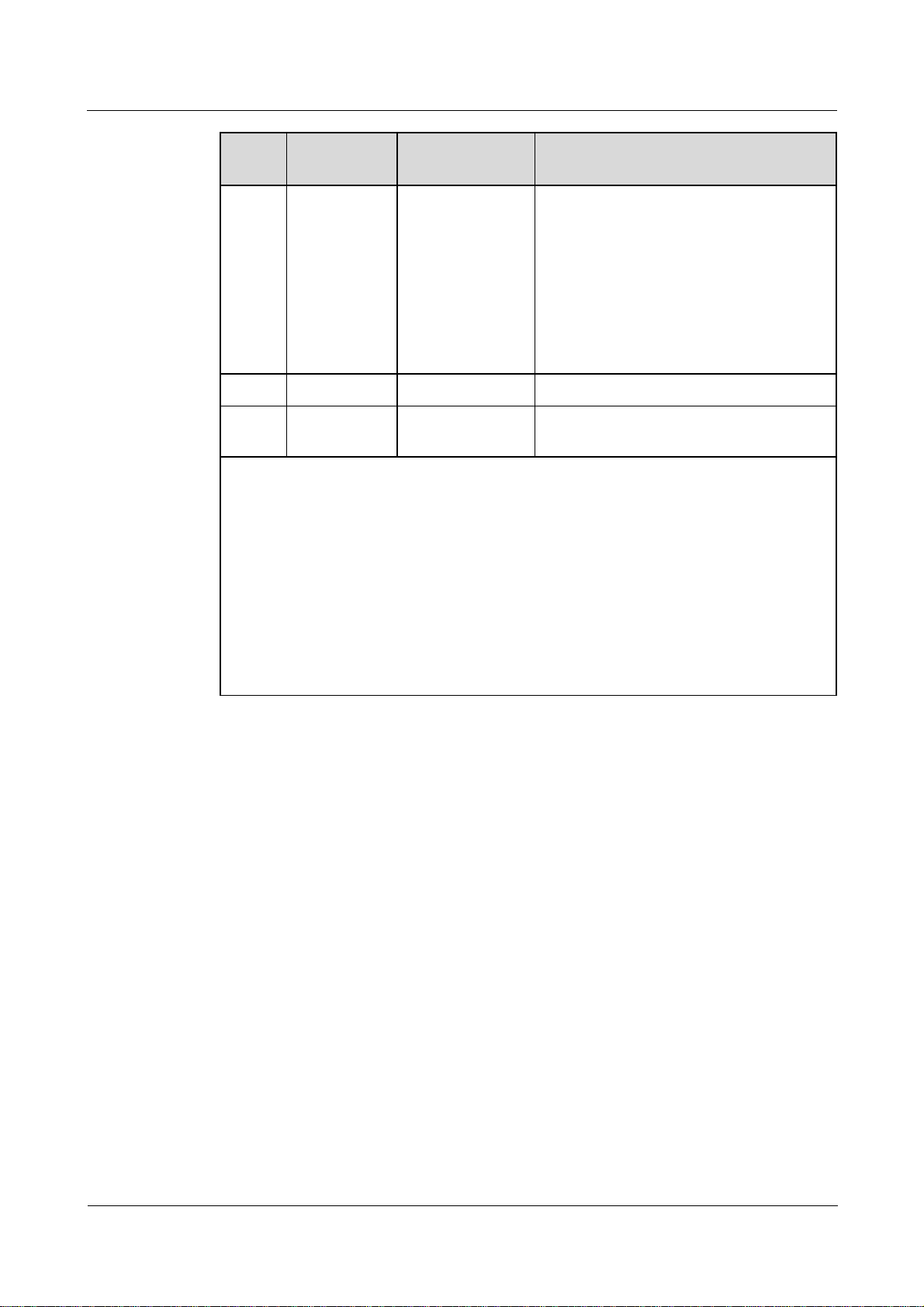
No. Port (Silk
Function Description
Screen)
12 AI1–AI8 Analog input SmartLogger2000-10CN: AI1–AI4:
4–20 mA and 0–20 mA input current
(passive); AI5–AI8: 4–20mA and 0–20
mA input current (active)
Other models: AI1: 0–10 V input
voltage (passive); AI2–AI4: 4–20 mA
and 0–20 mA input current (passive);
AI5–AI8: 4–20 mA and 0–20 mA input
current (active)
13 AO1–AO6 Analog output 4–20 mA and 0–20 mA current output.
14 DI1–DI8 Digital parameter
Connects to a dry contact input.
input
d:
If the APP fails to connect to the SmartLogger or you have forgotten the IP address, you
can press the Default key to reset the Bluetooth module or restore the IP address to the
default IP address (192.168.0.10).
To reset and restart the Bluetooth module, press and hold down the Default key for
3–10s until the BLU indicator blinks at short intervals (0.125s on and 0.125s off) and all
other indicators are off, and then release the Default key.
To restore the IP address to the default IP address, press and hold down the Default key
for more than 10s until the RUN indicator blinks at short intervals (0.125s on and
0.125s off) and all other indicators are off, and then release the Default key. The
operation is valid within 5 minutes.
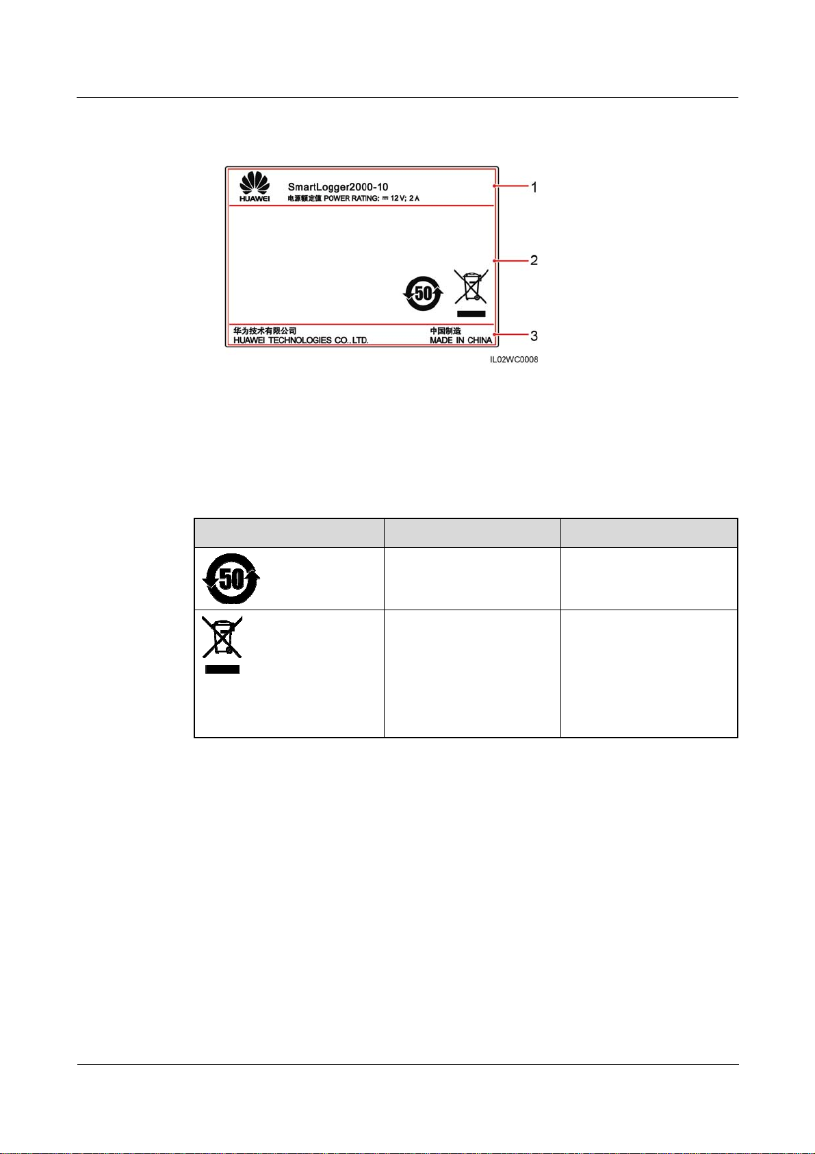
2.3 Nameplate Description
A nameplate is attached at the back of the SmartLogger. The content of the nameplate
includes the SmartLogger model, rated power supply specifications, and compliance symbols,
as shown in Figure 2-5.
(2016-06-20) Huawei Proprietary and Confidential
Copyright © Huawei Technologies Co., Ltd.
10
SmartLogger2000
User Manual 2 Overview
Figure 2-5 Nameplate
(1) Trademark, product model, and rated power
supply specifications
(3) Company name and country of manufacture
Table 2-3 Compliance symbols
Symbol Name Meaning
Environmentally friendly
use period (EFUP) label
EU waste electrical and
electronic equipment
(WEEE) label
(2) Compliance symbols
This product does not
pollute the environment
during a specified period.
Do not dispose of the
SmartLogger as household
garbage. For details about
how to deal with the
undesirable SmartLogger,
refer to 8 Disposing of the
SmartLogger.
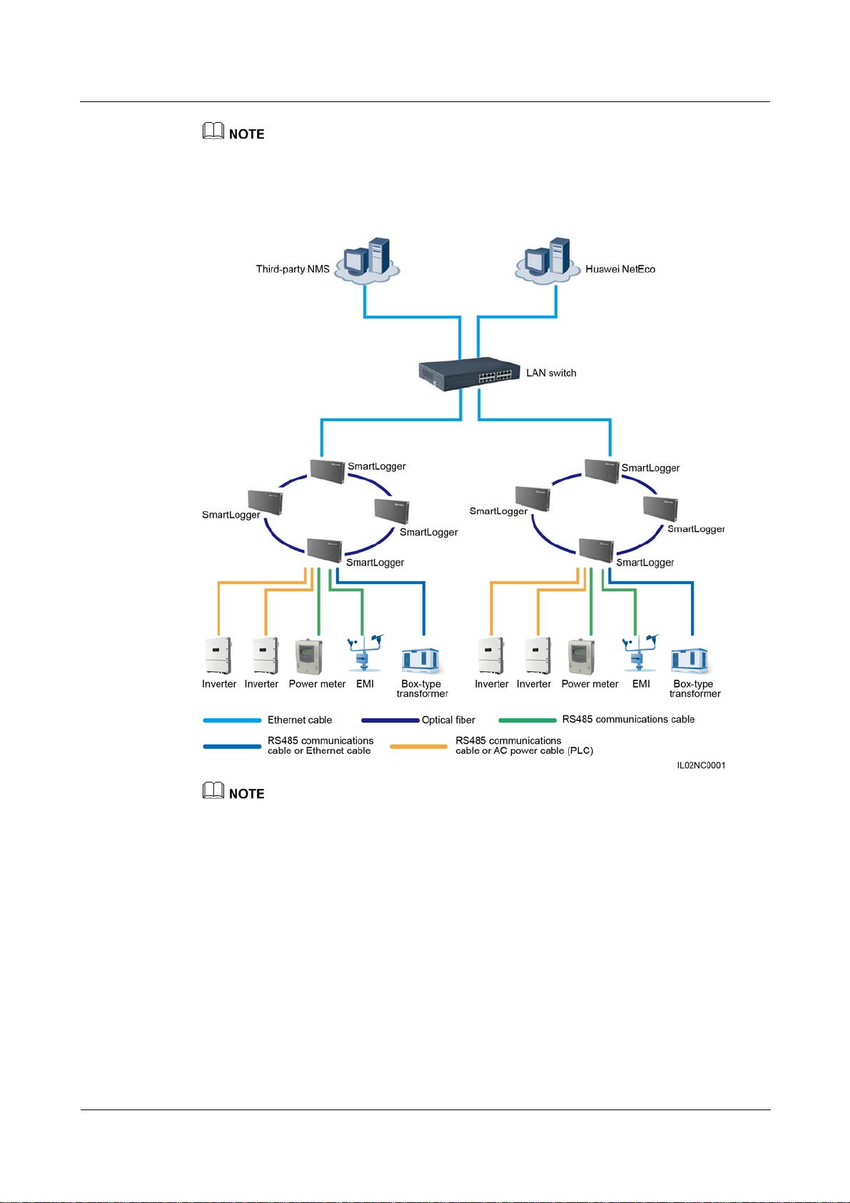
2.4 Typical Networking Scenarios
Fiber+RS485/PLC Networking
A fiber network can be a ring network or a star network, as shown in Figure 2-6 and Figure
2-7 respectively.
In the fiber networking, the SmartLogger connects to an inverter over an RS485
communications cable or an AC power cable, connects to a box-type transformer over the
RS485 communications cable or Ethernet network cable, and connects to southbound devices
such as the EMI and power meter over the RS485 communications cable.
(2016-06-20) Huawei Proprietary and Confidential
Copyright © Huawei Technologies Co., Ltd.
11
SmartLogger2000
User Manual 2 Overview
The SmartLogger is integrated with the PLC central coordinator (CCO) that can work with the
SUN2000 integrated with the PLC station (STA) to implement power line communication (PLC)
networking over power cables.
Figure 2-6 Ring fiber network diagram
The SmartLogger provides two 100M Ethernet optical ports to implement ring networking.
A maximum of 16 SmartLoggers can be connected to form a fiber ring network. Each SmartLogger
can connect to southbound devices such as the inverter, EMI, and power meter.
Multiple fiber ring networks can converge over an Ethernet switch or SmartLogger and then connect
to an NMS.
(2016-06-20) Huawei Proprietary and Confidential
Copyright © Huawei Technologies Co., Ltd.
12
SmartLogger2000
User Manual 2 Overview
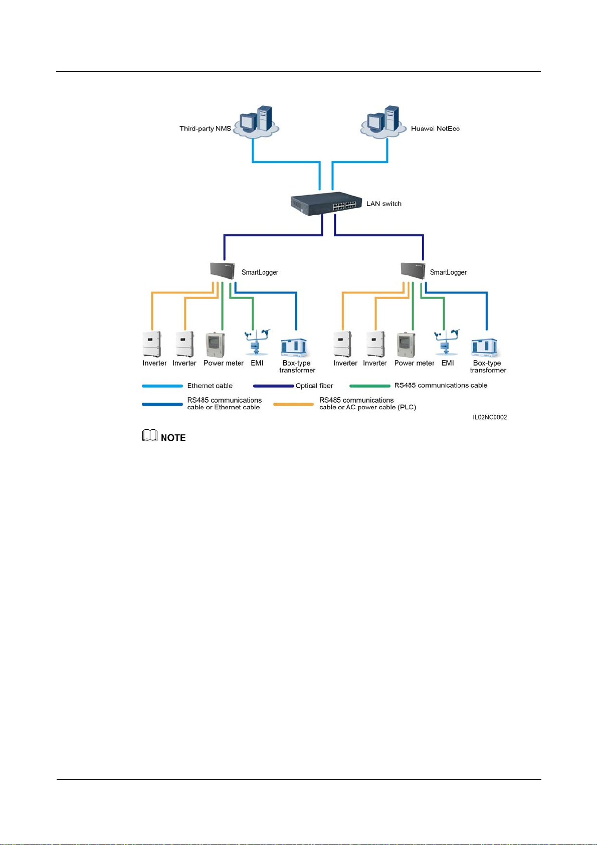
Figure 2-7 Start fiber network diagram
Multiple SmartLoggers can converge over an Ethernet switch and then connect to an NMS.
The SmartLogger connects to the Ethernet switch over optical fibers with the maximum
communications distance of 12 km in between.
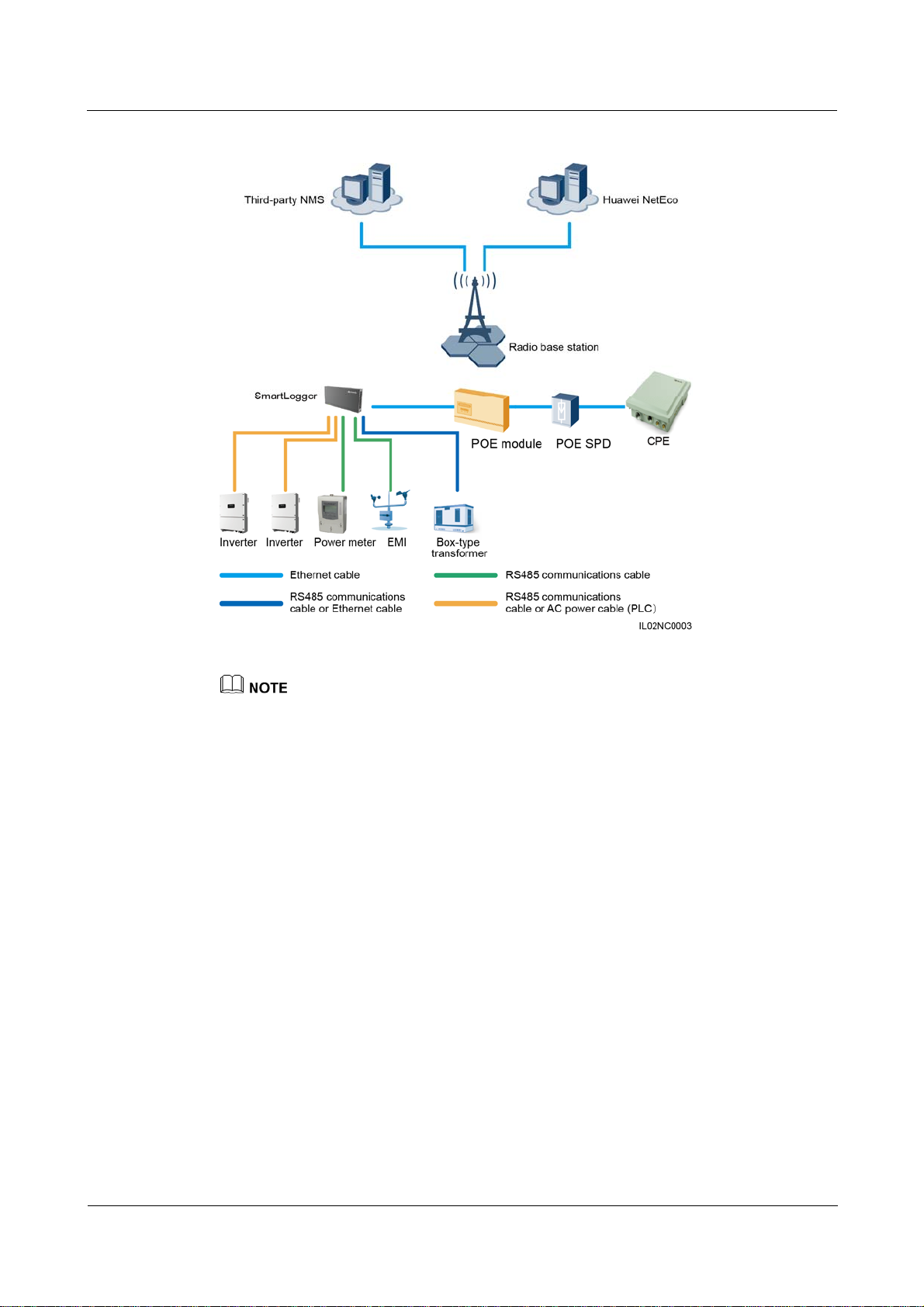
LTE+RS485/PLC Networking
Figure 2-8 shows the LTE+RS485/PLC networking diagram.
In the LTE wireless networking scenario, the SmartLogger connects to the inverter over an
RS485 communications cable or an AC power cable, connects to a box-type transformer over
the RS485 communications cable or Ethernet network cable, connects to southbound devices
such as the EMI and power meter over the RS485 communications cable, connects to a
customer premises equipment (CPE) over an Ethernet electrical port, and transmits
information collected from southbound devices to an NMS in wireless mode.
(2016-06-20) Huawei Proprietary and Confidential
Copyright © Huawei Technologies Co., Ltd.
13
SmartLogger2000
User Manual 2 Overview
Figure 2-8 LTE+RS485/PLC network diagram
The IP addresses for the SmartLogger, CPE, and monitoring devices in the box-type transformer
must be in the same network segment.
The IP address planned for the SmartLogger needs to be imported to the third-party NMS for the
NMS to proactively connect to the SmartLogger.
The IP address planned for the box-type transformer needs to be imported to the third-party NMS for
the NMS to proactively connect to the box-type transformer.
2.5 System Wiring Diagram
(2016-06-20) Huawei Proprietary and Confidential
Copyright © Huawei Technologies Co., Ltd.
14
SmartLogger2000
User Manual 2 Overview
The general power input cable of the SmartACU2000 smart array controller (smart array
controller for short) needs to be prepared by the customer. Recommended cable: four-core
multi-wire (L1, L2, L3, and GND) armored; operating voltage to the ground: ≥ 600 V; and
cross sectional area of a single core: 4mm
The cable from the busbar to the knife switch needs to be prepared by the customer.
Recommended cable: three-core multi-wire (L1, L2, and L3); operating voltage to the
ground: ≥ 600 V; cross sectional area of a single core: 4 mm
The SmartLogger can be connected to the SUN2000 through an RS485 communications
2
.
2
.
cable or AC power cable. If the RS485 communications mode is used, no AC power cable
is required between the SmartLogger and the X1 terminal block in the scenario with smart
array controllers; no AC power cable is required between the SmartLogger and the MCB
in the scenario without smart array controllers.
If the SmartLogger uses the RS485 communications mode, it is recommended that at least
two RS485 signal SPDs be installed. A maximum of three RS485 signal SPDs can be
installed for each site.
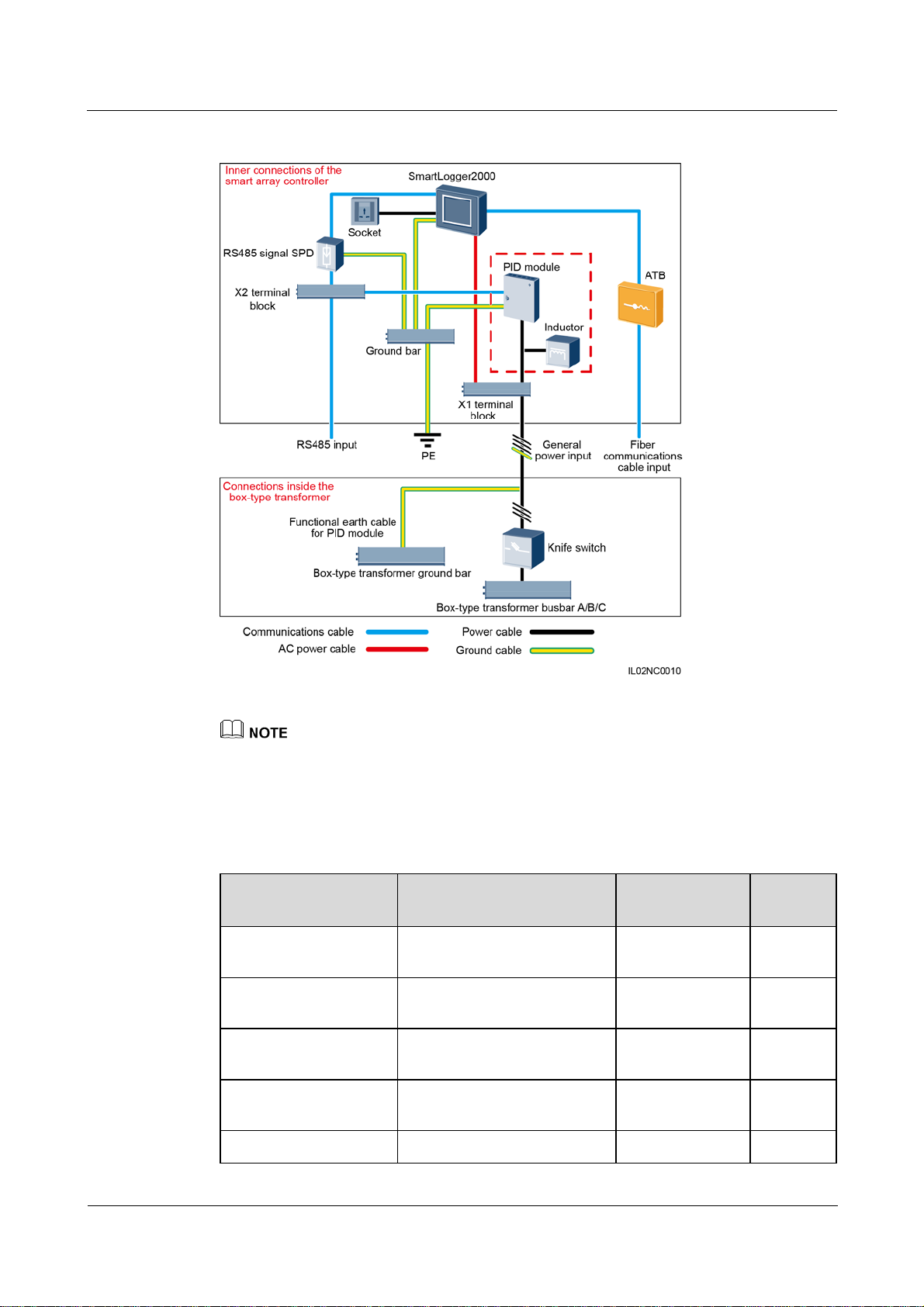
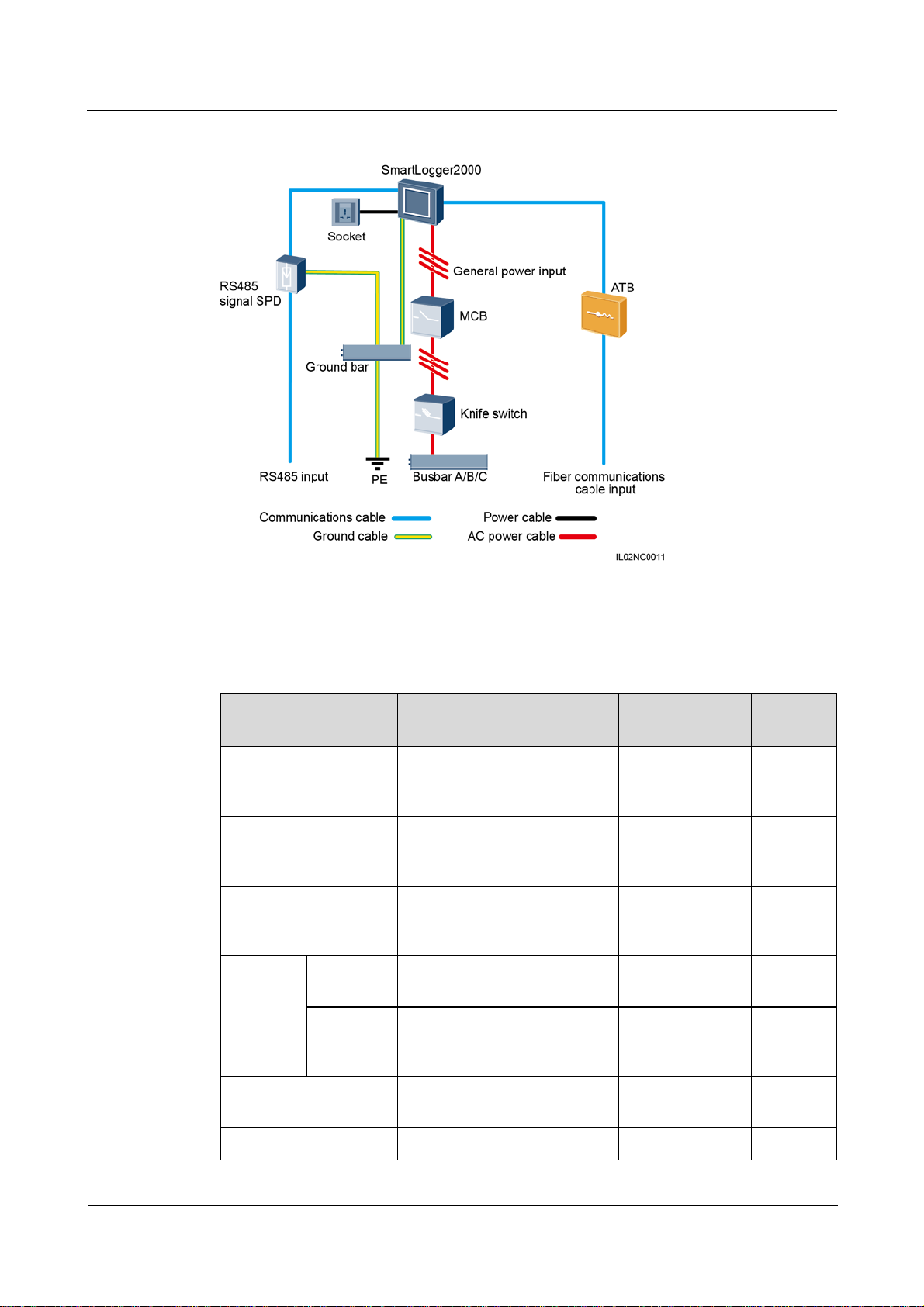
Scenario With a Smart Array Controller
The smart array controller, also a communication box, is an outdoor cabinet that controls the
communication of the PV array in a PV plant. The cabinet can house components such as the
SmartLogger, RS485 signal SPD, PID module, inductor, ATB, PoE module, and PoE SPD.
The PID module and inductor are configured only in the smart array controller with the PID module
and have been installed before delivery.
(2016-06-20) Huawei Proprietary and Confidential
Copyright © Huawei Technologies Co., Ltd.
15
SmartLogger2000
User Manual 2 Overview
Figure 2-9 Fiber+RS485/PLC
The X1 terminal block (general power input and AC output) and X2 terminal block (RS485
communications port) are in the upper part on the rear of the smart array controller.
Table 2-4 lists the components required for the fiber+RS485/PLC networking mode in the
scenario with a smart array controller.
Table 2-4 Components required
Component Recommended Model or
Type Quantity
Specifications
PID module (optional) PID01 Installed before
1 PCS
delivery
PID inductor (working
with the PID module)
SmartLogger SmartLogger2000 Installed before
EIFI50ohm Installed before
1 PCS
delivery
1 PCS
delivery
RS485 signal SPD SPM01A Installed before
3 PCS
delivery
ATB CT-GZF2PJ-8 or Optional; can be 1 PCS
(2016-06-20) Huawei Proprietary and Confidential
Copyright © Huawei Technologies Co., Ltd.
16
SmartLogger2000
User Manual 2 Overview
Component Recommended Model or
Specifications
CT-GPH-A-8
Knife
switch
Fuse Rated voltage: ≥ 500 V; rated
current: 6 A
Knife
switch box
Rated voltage: ≥ 500 V; rated
current: ≥ 6 A; number of
phases: three
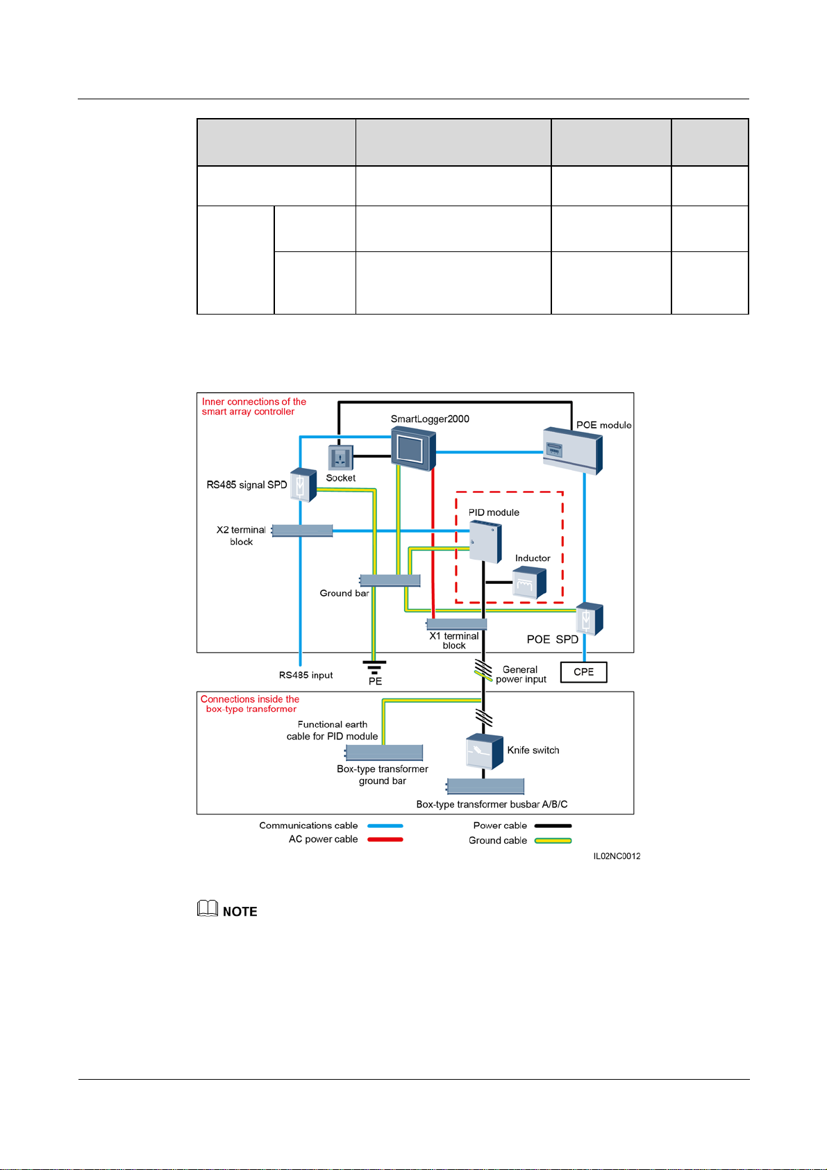
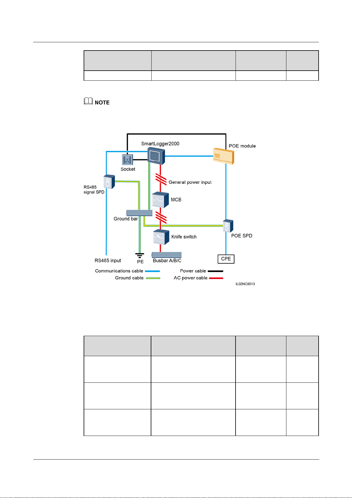
Figure 2-10 LTE+RS485/PLC
Type Quantity
purchased from
Huawei
Prepared by the
3 PCS
customer
Prepared by the
1 PCS
customer
The X1 terminal block (general power input and AC output) and X2 terminal block (RS485
communications port) are in the upper part on the rear of the smart array controller.
Table 2-5 lists the components required for the LTE+RS485/PLC networking mode in the
scenario with a smart array controller.
(2016-06-20) Huawei Proprietary and Confidential
Copyright © Huawei Technologies Co., Ltd.
17
SmartLogger2000
User Manual 2 Overview
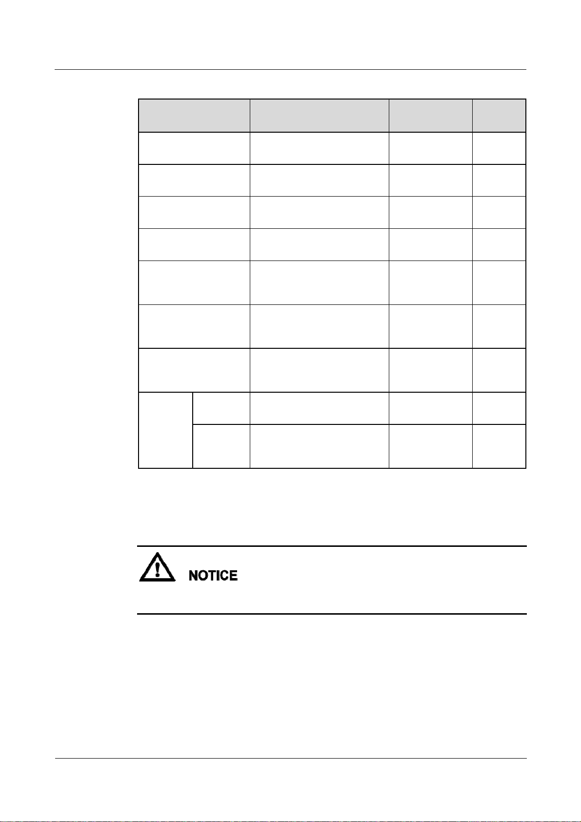
Table 2-5 Components required
Component Recommended Model or
Type Quantity
Specifications
PID module (optional) PID01 Installed before
1 PCS
delivery
PID inductor (working
with the PID module)
SmartLogger SmartLogger2000 Installed before
EIFI50ohm Installed before
1 PCS
delivery
1 PCS
delivery
RS485 signal SPD SPM01A Installed before
3 PCS
delivery
PoE module POE35-54A or POE85-56A Optional; can be
1 PCS
purchased from
Huawei
POE SPD POE-2A Optional; can be
1 PCS
purchased from
Huawei
CPE EG860V2-C71 Optional; can be
1 PCS
purchased from
Huawei
Knife
switch
Fuse Rated voltage: ≥ 500 V; rated
current: 6 A
Knife
switch box
Rated voltage: ≥ 500 V; rated
current: ≥ 6 A; number of
phases: three
Scenario Without a Smart Array Controller
If the SmartLogger uses an AC power cable for communication, an MCB or a knife switch
needs to be installed to prevent device damage in the case of short circuits
Prepared by the
customer
Prepared by the
customer
3 PCS
1 PCS
(2016-06-20) Huawei Proprietary and Confidential
Copyright © Huawei Technologies Co., Ltd.
18
SmartLogger2000
User Manual 2 Overview
Figure 2-11 Fiber+RS485/PLC
Table 2-6 lists the components required for the fiber+RS485/PLC networking mode in the
scenario without a smart array controller.
Table 2-6 Components required
Component Recommended Model or
Type Quantity
Specifications
SmartLogger SmartLogger2000 Optional; can be
1 PCS
purchased from
Huawei
RS485 signal SPD X4B-05 Optional; can be
3 PCS
purchased from
Huawei
ATB CT-GZF2PJ-8 or
CT-GPH-A-8
Optional; can be
purchased from
1 PCS
Huawei
Knife
switch
Fuse Rated voltage: ≥ 500 V; rated
current: 6 A
Prepared by the
customer
3 PCS
Knife
switch box
Rated voltage: ≥ 500 V; rated
current: ≥ 6 A; number of
Prepared by the
customer
1 PCS
phases: three
MCB Rated voltage: ≥ 500 V; rated
current: ≥ 6 A
Prepared by the
customer
1 PCS
Socket Matching with the power Prepared by the 1 PCS
(2016-06-20) Huawei Proprietary and Confidential
Copyright © Huawei Technologies Co., Ltd.
19
SmartLogger2000
User Manual 2 Overview
Component Recommended Model or
Type Quantity
Specifications
adapter customer
Length of the cable used for connecting components depends on the survey result.
Figure 2-12 LTE+RS485/PLC
Table 2-7 lists the components required for the LTE+RS485/PLC networking mode in the
scenario without a smart array controller.
Table 2-7 Components required
Component Recommended Model or
Type Quantity
Specifications
SmartLogger SmartLogger2000 Optional; can be
1 PCS
purchased from
Huawei
RS485 signal SPD X4B-05 Optional; can be
3 PCS
purchased from
Huawei
PoE module POE35-54A or POE85-56A Optional; can be
1 PCS
purchased from
Huawei
(2016-06-20) Huawei Proprietary and Confidential
Copyright © Huawei Technologies Co., Ltd.
20
SmartLogger2000
User Manual 2 Overview
Component Recommended Model or
Type Quantity
Specifications
POE SPD POE-2A Optional; can be
purchased from
Huawei
CPE EG860V2-C71 Optional; can be
purchased from
Huawei
Knife
switch
Fuse Rated voltage: ≥ 500 V; rated
current: 6 A
Knife
switch box
Rated voltage: ≥ 500 V; rated
current: ≥ 6 A; number of
Prepared by the
customer
Prepared by the
customer
phases: three
MCB Rated voltage: ≥ 500 V; rated
current: ≥ 6 A
Socket Matching with the power
adapter
Prepared by the
customer
Prepared by the
customer
1 PCS
1 PCS
3 PCS
1 PCS
1 PCS
1 PCS
Length of the cable used for connecting components depends on the survey result.
(2016-06-20) Huawei Proprietary and Confidential
Copyright © Huawei Technologies Co., Ltd.
21
SmartLogger2000
User Manual 3 Installation
3 Installation
About This Chapter
This topic describes how to install the SmartLogger.
Context
Install the SmartLogger in an appropriate position and surface.
Do not store the SmartLogger in areas with flammable or explosive materials.
Do not install the SmartLogger on flammable building materials.
3.1 Checking Before Installation
3.2 Preparing Tools
3.3 Determining the Installation Position
3.4 Installing the SmartLogger
3.5 Installing the RS485 signal SPD
3.1 Checking Before Installation
Checking Outer Packing Materials
Check the outer packing materials for damage before unpack the SmartLogger, such as holes
and cracks. If any damage is found, do not unpack the SmartLogger and contact the dealer as
soon as possible.
(2016-06-20) Huawei Proprietary and Confidential
Copyright © Huawei Technologies Co., Ltd.
22
SmartLogger2000
User Manual 3 Installation
Checking Deliverables
After unpacking the SmartLogger, check whether deliverables are intact and complete. If any
damage is found or any component is missing, contact the dealer.
For details about the number of accessories delivered with the SmartLogger, see the Packing List in the
packing case.
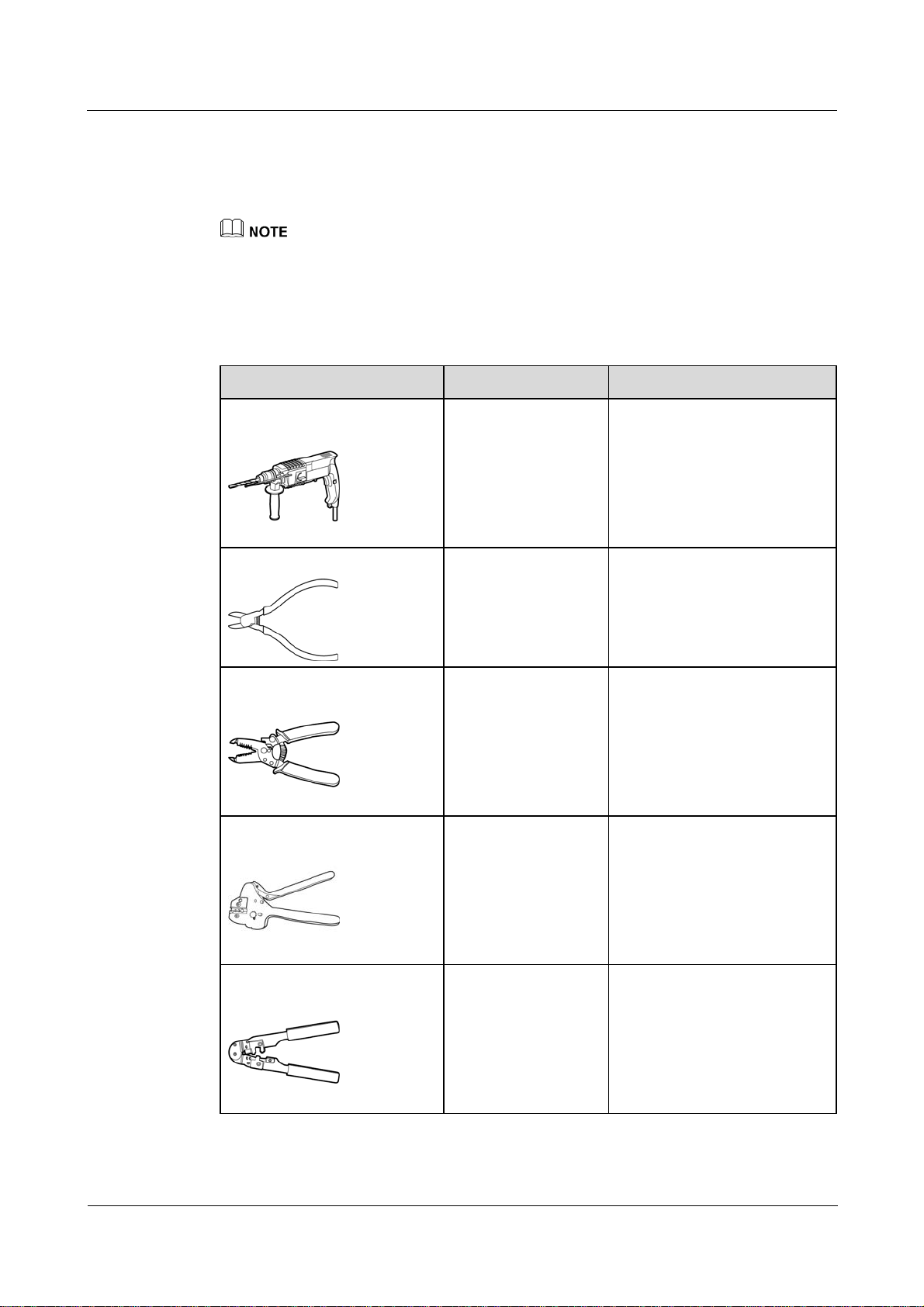
3.2 Preparing Tools
Tools Model Function
Hammer drill
Diagonal pliers
Wire stripper
Crimping tool
Drill bit (Ф6 mm) Drills holes in the wall when
the SmartLogger is
wall-mounted.
N/A Cuts and tighten cable ties.
N/A Peels cable jackets.
H4TC0001
Manufacturer:
AMPHENOL
Crimps cables.
RJ45 crimping tool
(2016-06-20) Huawei Proprietary and Confidential
Copyright © Huawei Technologies Co., Ltd.
N/A Crimps RJ45 connectors for
communications cables.
23

SmartLogger2000
User Manual 3 Installation
Tools Model Function
Flat-head screwdriver
Rubber mallet
Guarded blade utility knife
Cable cutter
3x100 Tightens screws on the cable
terminal block.
N/A Hammers expansion sleeves
into holes.
N/A Removes package.
N/A Cuts cables.
Vacuum cleaner
Marker
N/A Cleans up dust after holes are
drilled.
Diameter: ≤ 10 mm Marks signs.
(2016-06-20) Huawei Proprietary and Confidential
Copyright © Huawei Technologies Co., Ltd.
24

SmartLogger2000
User Manual 3 Installation
Tools Model Function
Measuring tape
Safety goggles
Anti-dust respirator
Torque screwdriver
N/A Measures distance
N/A Protect your eyes during hole
drilling.
N/A Prevents dust from entering
your mouth and nostrils during
hole drilling.
Phillips head: M4 and
ST3.5
Tightens screws during device
installation.
Heat gun
N/A Heat-shrinks a tube.
Cable tie
N/A Binds cables.
3.3 Determining the Installation Position
Observe the following requirements when determining the installation position:
Do not install the SmartLogger outdoors because it is protected to IP20.
Install the SmartLogger in a dry environment to protect it against water.
(2016-06-20) Huawei Proprietary and Confidential
Copyright © Huawei Technologies Co., Ltd.
25
SmartLogger2000
User Manual 3 Installation
Keep the product in an ambient temperature range of –40°C to +60°C and away from
direct sunlight.
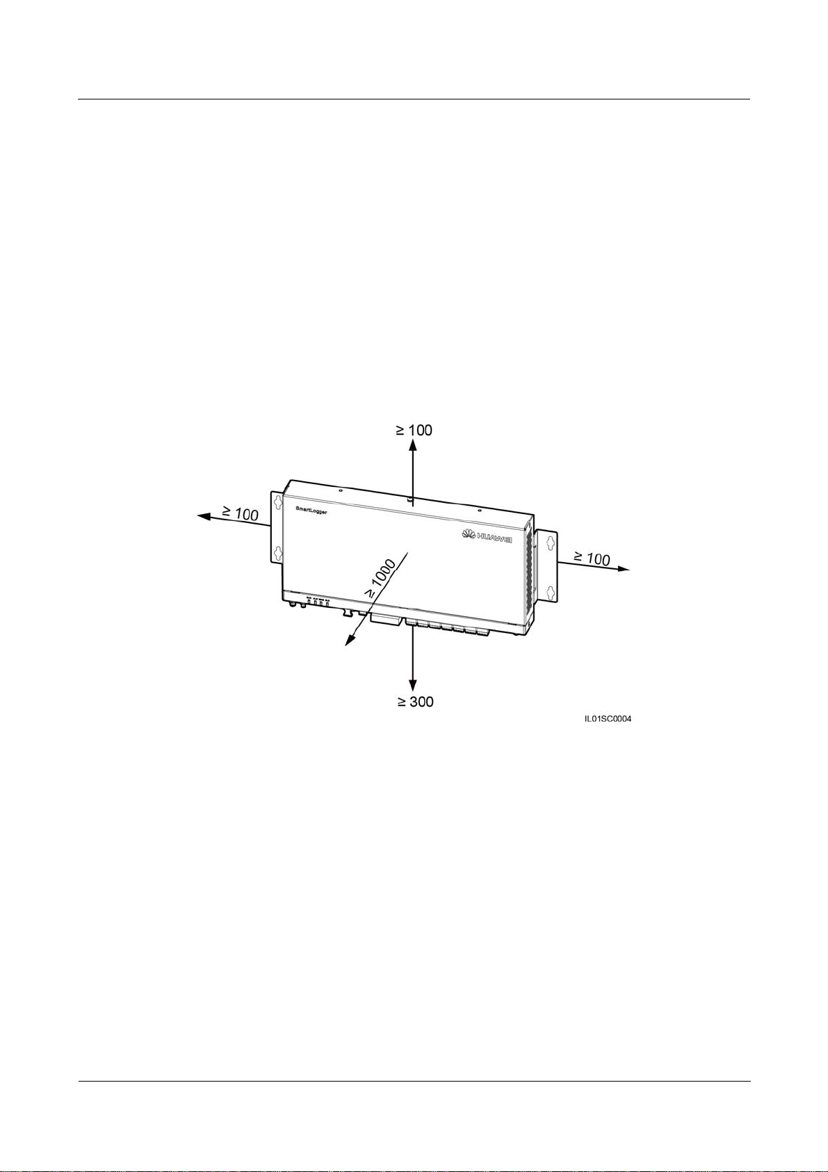
The communications distance must not exceed 1000 m for the RS485 port, and must not
exceed 100 m for the Ethernet port.
Install the SmartLogger at a proper height to facilitate operation and maintenance.
Do not place the SmartLogger upside down; otherwise, dust will fall into ports at the
bottom of the SmartLogger, thereby reducing the service life.
The installation mode and position must be suitable for the SmartLogger weight (3800 g)
and dimensions with mounting ears (H x W x D: 411 mm x 170 mm x 58.6 mm).
If you install the SmartLogger on a wall or along a guide rail, the area for connecting
cables should be downwards.
Figure 3-1 and Figure 3-2 show the minimum distance between the SmartLogger and
surrounding objects.
Figure 3-1 The minimum clearance for wall-mounting (unit: mm)
(2016-06-20) Huawei Proprietary and Confidential
Copyright © Huawei Technologies Co., Ltd.
26

SmartLogger2000
User Manual 3 Installation
Figure 3-2 The minimum clearance for guide rail–mounting (unit: mm)
3.4 Installing the SmartLogger
Context
For a smart array controller, the SmartLogger is installed before delivery. In other scenarios,
the SmartLogger can be mounted on a wall or guide rail.
3.4.1 Mounting the SmartLogger on a Wall
Context
Install the SmartLogger on a solid and smooth wall to ensure that it can be secured on the
wall.
Before hanging the SmartLogger on the screws, secure the expansion sleeves, washers,
and tapping screws into the wall.
Figure 3-3 shows the distances between screw holes on the SmartLogger mounting ears.
(2016-06-20) Huawei Proprietary and Confidential
Copyright © Huawei Technologies Co., Ltd.
27

SmartLogger2000
User Manual 3 Installation
Figure 3-3 Distances between screw holes (unit: mm)
Figure 3-4 shows the screw assembly for wall-mounting:
Figure 3-4 Screw assembly for wall-mounting
Procedure
Step 1 Determine mounting holes based on the hole positions in the mounting ears, and mark the
(1) ST3.5 tapping screw (2) Washer (3) Expansion sleeve
mounting holes using a marker, as shown in Figure 3-5.
If you need to use a ladder to install the device on a high position, take measures to protect
yourself from falling down.
(2016-06-20) Huawei Proprietary and Confidential
Copyright © Huawei Technologies Co., Ltd.
28

SmartLogger2000
User Manual 3 Installation
Figure 3-5 Hole positions and dimensions (unit: mm)
Step 2 Drill holes by using a hammer drill and install expansion sleeves, washers, and tapping screws,
as shown in Figure 3-6.
Figure 3-6 Drilling holes and installing expansion sleeves, washers, and tapping screws (unit:
mm)
1. Put a hammer drill with a Ф6 mm drill bit on a marked hole position perpendicularly
against the wall and drill to a depth greater than or equal to 40 mm.
(2016-06-20) Huawei Proprietary and Confidential
Copyright © Huawei Technologies Co., Ltd.
29

SmartLogger2000
User Manual 3 Installation
To prevent dust inhalation or contact with eyes, wear safety goggles and an anti-dust
respirator when drilling holes.
Wipe away any dust in or around the holes and measure the hole distance. If the holes are
inaccurately positioned, drill holes again.
2. Slightly tighten the expansion sleeves, vertically insert them into holes, and knock them
completely into the holes by using a rubber mallet.
3. Drive the tapping screws into the expansion sleeves, and reserve 10 mm outside of the
holes.
Step 3 Put the tapping screws through the SmartLogger mounting ears and washers into the
mounting holes in the wall.
Ensure that the area for connecting cables in the SmartLogger is downwards for the ease of
electrical connections and maintenance.
Step 4 Tighten the tapping screws to a torque of 0.3 N·m using a torque screwdriver, as shown in
Figure 3-7.
Figure 3-7 Tightening the tapping screws
----End
(2016-06-20) Huawei Proprietary and Confidential
Copyright © Huawei Technologies Co., Ltd.
30

SmartLogger2000
User Manual 3 Installation
3.4.2 Mounting the SmartLogger Along a Guide Rail
Context
No guide rail is delivered with a SmartLogger. If you need to install a SmartLogger on a guide
rail, prepare a standard 35 mm wide guide rail. For details about the guide rail dimensions, see
Figure 3-8.
Figure 3-8 Guide rail dimensions (unit: mm)
Procedure
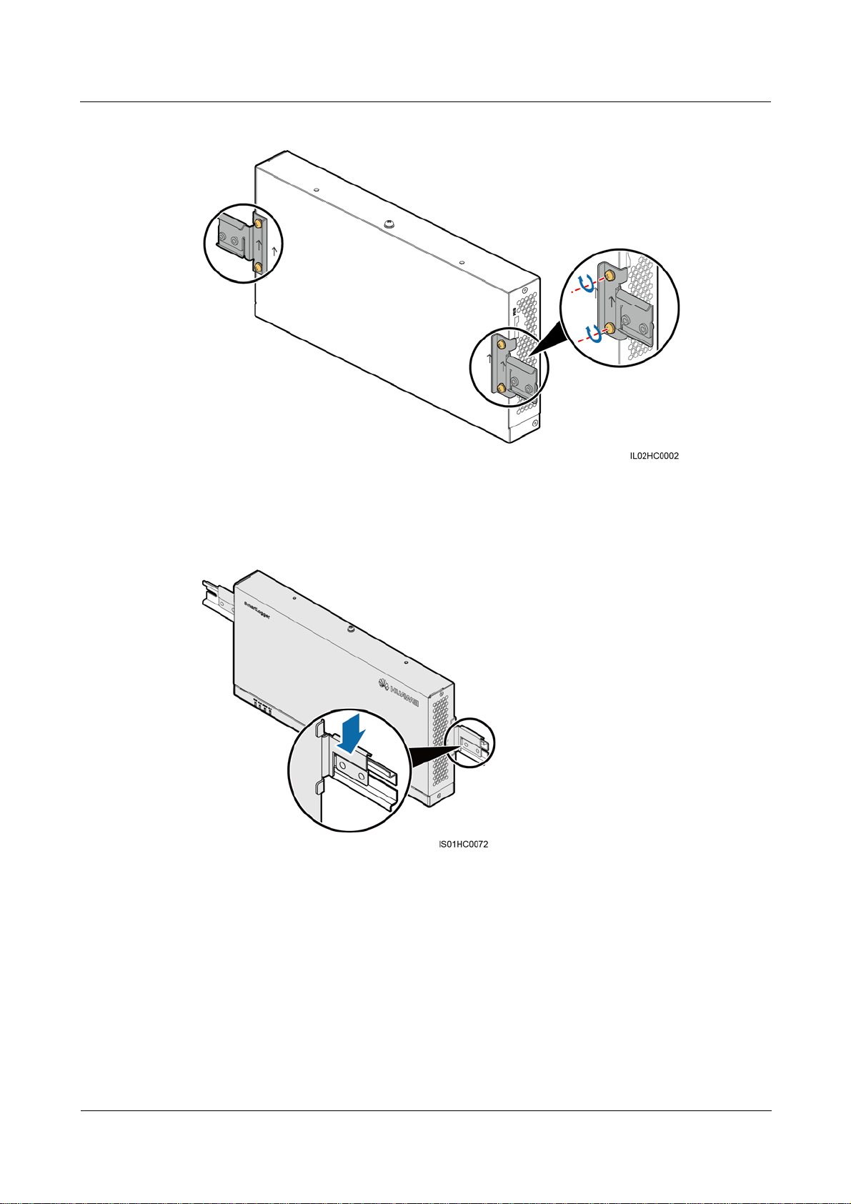
Step 1 Remove the mounting ears from the SmartLogger using a Phillips screwdriver, as shown in
Verify that the length of the guide rail is sufficient for securing the SmartLogger. The
recommended length is 450 mm or greater. If an RS485 signal SPD needs to be installed
on the guide rail, the recommended guide rail length is 600 mm or greater.
Secure the guide rail before mounting the SmartLogger.
Figure 3-9.
(2016-06-20) Huawei Proprietary and Confidential
Copyright © Huawei Technologies Co., Ltd.
31

SmartLogger2000
User Manual 3 Installation
Figure 3-9 Removing the mounting ears
Step 2 Secure the guide rail clamps using M4x8 screws removed from the mounting ears, and tight
the screws to a torque of 1.2 N·m, as shown in Figure 3-10.
Install the guide rail clamps exactly as shown in the figure; otherwise, you may not be able to
mount the SmartLogger onto the guide rail.
(2016-06-20) Huawei Proprietary and Confidential
Copyright © Huawei Technologies Co., Ltd.
32
SmartLogger2000
User Manual 3 Installation
Figure 3-10 Installing the guide rail clamps
Step 3 Mount the SmartLogger onto the guide rail, as shown in Figure 3-11.
Figure 3-11 Mounting the SmartLogger onto the guide rail
Step 4 Install the guide rails fastener using M4x12 screws, and tighten the screws to a torque wrench
of 1.2 N·m, as shown in Figure 3-12.
(2016-06-20) Huawei Proprietary and Confidential
Copyright © Huawei Technologies Co., Ltd.
33

SmartLogger2000
User Manual 3 Installation
Figure 3-12 Installing guide rail fasteners
----End
3.5 Installing the RS485 signal SPD
Context
If the SmartLogger needs to be connected to outdoor equipment through the COM port,
it is recommended that an RS485 signal SPD be installed.
Each RS485 signal SPD can connect to two COM ports. Each SmartLogger can be
configured with a maximum of three RS485 signal SPDs.
For a smart array controller, the RS485 signal SPD is installed before delivery. In other
scenarios, the RS485 signal SPD can be mounted on guide rail.
When determining the installation position, verify that the linear distance between the RS485 signal SPD
and the SmartLogger is no greater than 500 mm.
No guide rail is delivered with an RS485 signal SPD. If you need to install an RS485 signal
SPD on a guide rail, prepare a standard 35 mm wide guide rail with a length no less than 80
mm. For details about the guide rail dimensions, see Figure 3-8.
(2016-06-20) Huawei Proprietary and Confidential
Copyright © Huawei Technologies Co., Ltd.
34
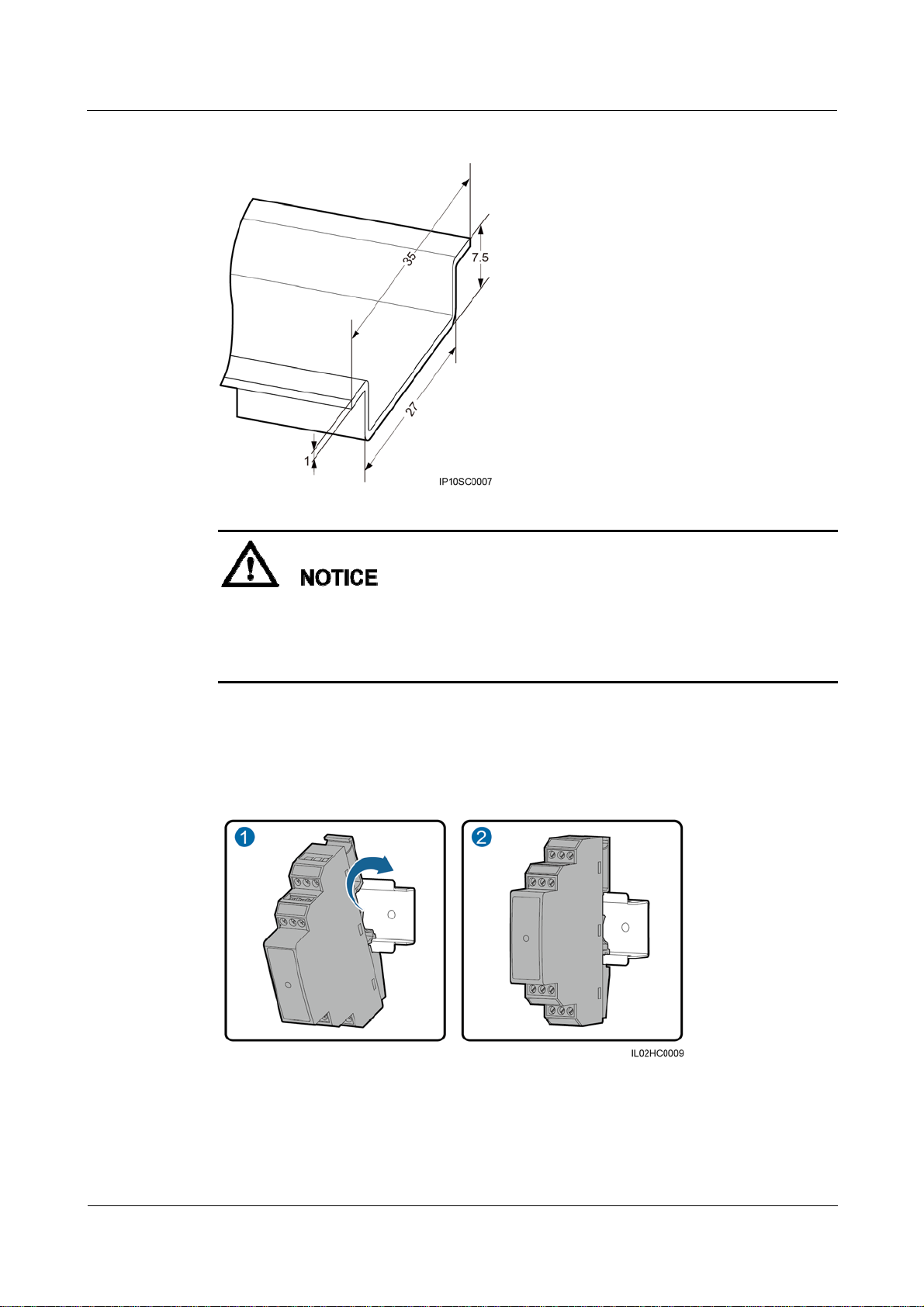
SmartLogger2000
User Manual 3 Installation
Figure 3-13 Guide rail dimensions (unit: mm)
Procedure
Step 1 Secure the RS485 signal SPD to the guide rail, as shown in Figure 3-14.
If the SmartLogger is installed on a guide rail, the RS485 signal SPD can share the guide
rail with the SmartLogger. In this case, the recommended guide rail length is 600 mm or
greater.
Secure the guide rail before mounting the RS485 signal SPD.
Figure 3-14 Securing the RS485 signal SPD to the guide rail
----End
(2016-06-20) Huawei Proprietary and Confidential
Copyright © Huawei Technologies Co., Ltd.
35

SmartLogger2000
User Manual 4 Connecting Cables
4 Connecting Cables
About This Chapter
Context
This section describes how to connect the SmartLogger to inverters and other devices in the scenario
without a smart array controller.
For a smart array controller, the SmartLogger and RS485 signal SPDs are installed before delivery.
For devices using the RS485 communications mode, connect the RS485 communications cable to
the X2 terminal block on the smart array controller. For devices using the PLC mode, connect the
AC power cable to the X1 terminal block on the smart array controller. For details about the two
connection methods, see SmartACU2000-C Smart Array Controller User Manual.
Ensure that all cables are connected securely.
The SmartLogger has no start key. Before the cable connections for the SmartLogger are
complete, do not connect a power adapter to it.
4.1 Connection Description
4.2 Connecting the PE Cable
The SmartLogger and SPD are separately connected to the ground bar for grounding
protection through a PE cable.
4.3 Connecting the RS485 signal SPD
4.4 Connecting Inverters
4.5 Connecting an EMI
4.6 Connecting a Power Meter
4.7 Connecting the Box-type Transformer
4.8 Connecting a PID Module
4.9 Connecting a Ripple Control Receiver
(2016-06-20) Huawei Proprietary and Confidential
Copyright © Huawei Technologies Co., Ltd.
36

SmartLogger2000
User Manual 4 Connecting Cables
4.10 Connecting an Ethernet Network Cable
4.11 Connecting Optical Fibers
4.1 Connection Description
Port Description
For the bottom view of the SmartLogger and port description, see Bottom of the Shell in 2.2
Appearance.
Device Connection Description
Figure 4-1 shows the recommended method for connecting the SmartLogger to multiple
devices through the COM ports. For details, see 4.3 Connecting the RS485 signal SPD–4.8
Connecting a PID Module.
Figure 4-1 Connecting the SmartLogger to multiple devices through the COM ports
4.2 Connecting the PE Cable
The SmartLogger and SPD are separately connected to the ground bar for grounding
protection through a PE cable.
4.2.1 Connecting the PE Cable for the SmartLogger
Prerequisites
The ground cable and OT terminals are available.
(2016-06-20) Huawei Proprietary and Confidential
Copyright © Huawei Technologies Co., Ltd.
37
SmartLogger2000
User Manual 4 Connecting Cables
Ground cable: outdoor copper-core cables with a cross sectional area of 4–6 mm2 or
12–10 AWG are recommended.
OT terminal: M6
Procedure
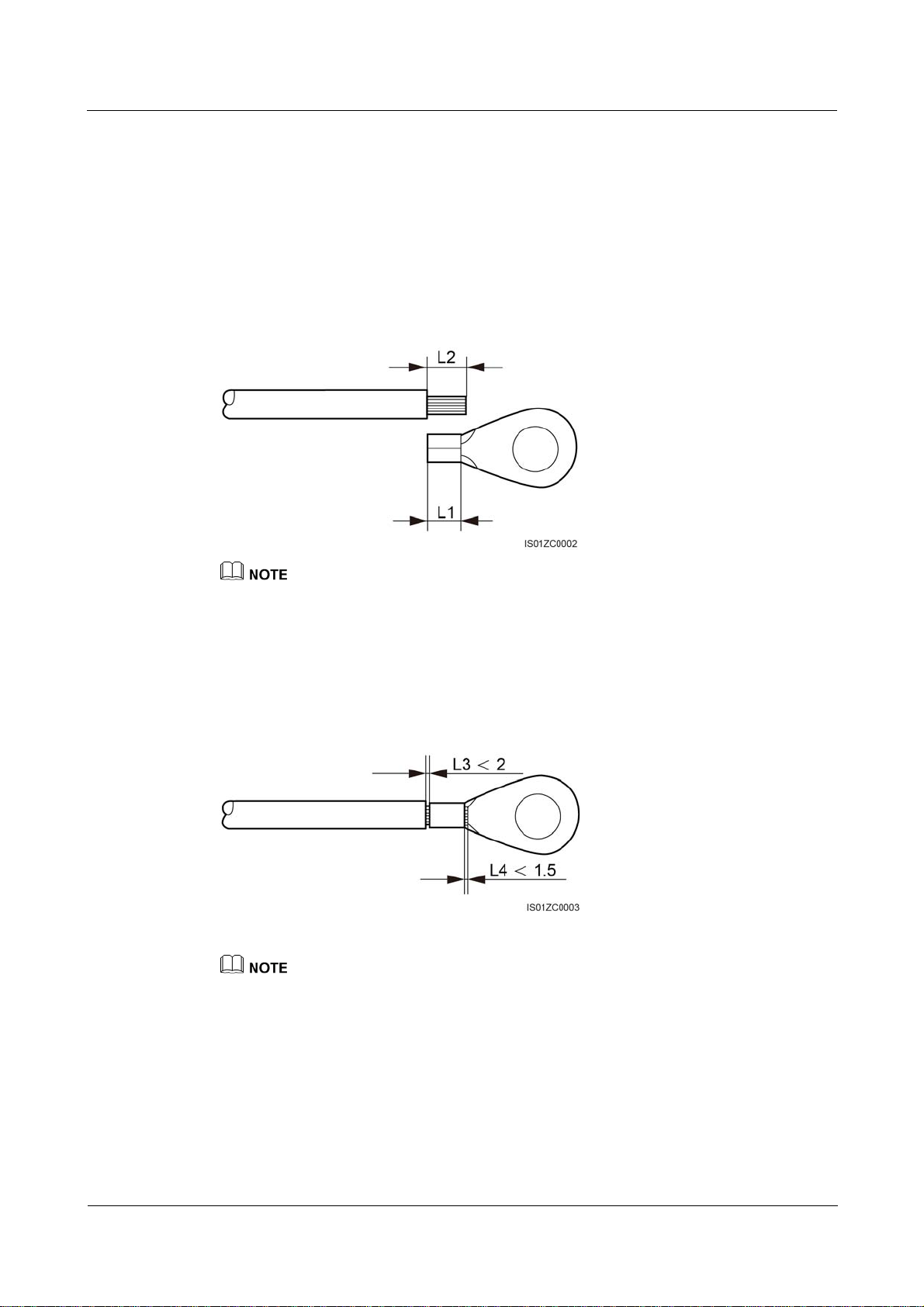
Step 1 Strip an appropriate length of the insulation layer using a wire stripper, as shown in Figure
4-2.
Figure 4-2 Stripping a PE cable (unit: mm)
The length of removed insulation layer (L2) must be 2–3 mm longer than the cable crimping length of
the OT terminal (L1).
Step 2 Insert the bare cable cores into the OT terminal and crimp them by using a crimping tool, as
shown in Figure 4-3.
Figure 4-3 Crimping the cable (unit: mm)
The cavity formed after the conductor crimp strip is crimped must wrap the core wires completely. The
core wires must contact the terminal closely.
Step 3 Remove the screws, spring washers, and flat washers from the ground point.
Step 4 Install the crimped OT terminal, flat washer, and spring washer onto the screw, and tighten
the screw to a torque of 1.4 N·m using a torque screwdriver, as shown in Figure 4-4.
(2016-06-20) Huawei Proprietary and Confidential
Copyright © Huawei Technologies Co., Ltd.
38

SmartLogger2000
User Manual 4 Connecting Cables
Figure 4-4 Connecting the PE cable to the SmartLogger
To enhance the anti-corrosion performance of the ground terminal, apply silica gel or paint on it after
connecting the PE cable.
For details about how to make the OT terminal at the other end of the cable, see Step 1 and
Step 2.
Connect the other end of the PE cable to the ground bar.
----End
4.2.2 Connecting the PE Cable for the RS485 Signal SPD
Prerequisites
The ground cable and OT terminals are available.
Ground cable: outdoor copper-core cables with a cross sectional area of 4 mm2 or 12
AWG are recommended.
OT terminal: M6
Procedure
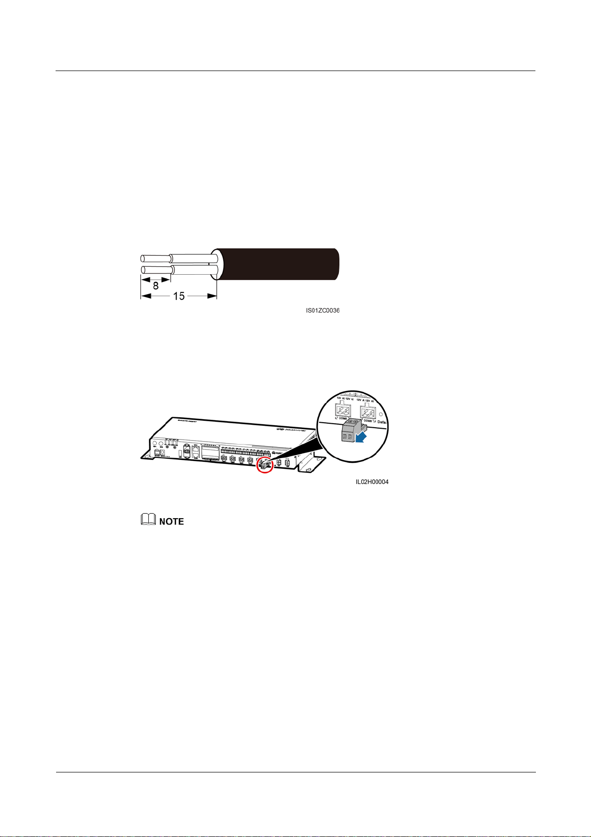
Step 1 Remove 8 mm of the insulation layer from the ground cable using the wire stripper.
Step 2 Insert the bare cable cores into port 3 of the RS485 signal SPD, as shown by (1) in Figure 4-5.
(2016-06-20) Huawei Proprietary and Confidential
Copyright © Huawei Technologies Co., Ltd.
39

SmartLogger2000
User Manual 4 Connecting Cables
Figure 4-5 Connecting the PE cable for the RS485 signal SPD
Step 3 Use a flat-head screwdriver to tighten the screws on port 3, as shown by (2) in Figure 4-5.
To enhance the anti-corrosion performance of the ground terminal, apply silica gel or paint on it after
connecting the PE cable.
For details about how to make the OT terminal at the other end of the cable, see Step 1 and
Step 2 in 4.2.1 Connecting the PE Cable for the SmartLogger.
Connect the other end of the PE cable to the ground bar.
----End
4.3 Connecting the RS485 signal SPD
Prerequisites
A two-core or multi-core communications cable with a wire cross sectional area of 0.5–2.5
2
has been prepared.
mm
Context
The way of connecting two to three RS485 signal SPDs is the same as the way of connecting one RS485
signal SPD.
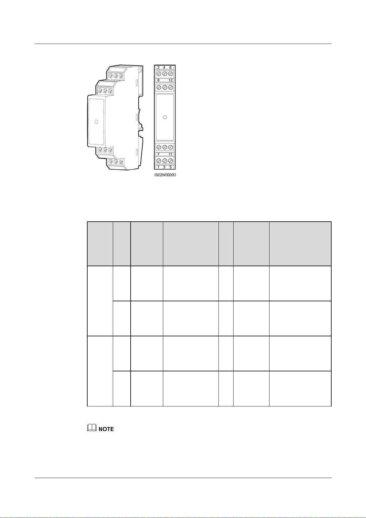
One RS485 signal SPD provides two RS485 surge protection ports, as shown in Figure 4-6.
(2016-06-20) Huawei Proprietary and Confidential
Copyright © Huawei Technologies Co., Ltd.
40
SmartLogger2000
User Manual 4 Connecting Cables
Figure 4-6 Ports on an RS485 signal SPD
Table 4-1 describes the surge protection ports.
Table 4-1 Port description
RS485
Surge
Protec
tion
Port
RS485
surge
Pro
Port
tect
Definiti
ion
on
Por
t
2 RS485A
IN
protect
ion
port 1
6 RS485B
IN
RS485
surge
8 RS485A
IN
protect
ion
port 2
12 RS485B
IN
Function Su
rg
e
Po
rt
RS485A, for
1 RS485A
RS485 positive
differential
signaling
RS485B, for
5 RS485B
RS485 negative
differential
signaling
RS485A, for
7 RS485A
RS485 positive
differential
signaling
RS485B, for
11 RS485B
RS485 negative
differential
signaling
Port
Definitio
n
OUT
OUT
OUT
OUT
Function
RS485A, for RS485
positive differential
signaling
RS485B, for RS485
negative differential
signaling
RS485A, for RS485
positive differential
signaling
RS485B, for RS485
negative differential
signaling
Protection ports are connected to COM ports on the SmartLogger. Port 4 is not connected.
Surge ports are connected to RS485 ports of other devices. Port 3 is the ground port.
Protection ports and Surge ports must not be reversely connected.
One RS485 signal SPD can protect two COM ports.
(2016-06-20) Huawei Proprietary and Confidential
Copyright © Huawei Technologies Co., Ltd.
41
SmartLogger2000
User Manual 4 Connecting Cables
Protection ports 2 and 6 and Surge ports 1 and 5 form an RS485 signal SPD port for protecting one
COM port. Protection ports 8 and 12 and Surge ports 7 and 11 form another RS485 signal SPD port
for protecting one more COM port.
An RS485 signal SPD port supports cables with a maximum cross sectional area of 2.5 mm2. If
devices need to be connected to an RS485 port in parallel, use cables with a cross sectional area of 1
mm2, and connect no more than two cables to the same port.
Procedure
Step 1 Remove an appropriate length of steel armor and insulation layer from the cable using a wire
stripper, as shown in Figure 4-7.
Figure 4-7 Stripping an RS485 communications cable (unit: mm)
Step 2 Remove the terminal block from the SmartLogger COM port, as shown in Figure 4-8.
Figure 4-8 Connecting the terminal block
For details about the definitions of SmartLogger COM ports, see Context in Connecting the
SUN2000 Using an RS485 Communications Cable of 4.4.1 Connecting the SUN2000.
Remove the terminal block using a flat-head screwdriver.
Step 3 Insert the bare cable cores into the terminal block, as shown by (1) in Figure 4-9.
(2016-06-20) Huawei Proprietary and Confidential
Copyright © Huawei Technologies Co., Ltd.
42

SmartLogger2000
User Manual 4 Connecting Cables
Figure 4-9 Cable connection for the terminal block
Step 4 Use a flat-head screwdriver to tighten the screws on the terminal block, as shown by (2) in
Figure 4-9.
Step 5 Insert the terminal block into the SmartLogger COM port.
Step 6 Insert the bare cable cores at the other end of the cable into a Protection port of the RS485
signal SPD, as shown by (1) in Figure 4-10.
Figure 4-10 Wiring diagram for the RS485 signal SPD
Verify that the COM+ (RS485A) port on the SmartLogger is connected to Protection port 2
or 8 on the RS485 signal SPD, and that the COM- (RS485B) port on the SmartLogger is
connected to Protection port 6 or 12 on the RS485 signal SPD.
Step 7 Use a flat-head screwdriver to tighten the screws on the Protection ports, as shown by (2) in
Figure 4-10.
----End
(2016-06-20) Huawei Proprietary and Confidential
Copyright © Huawei Technologies Co., Ltd.
43

SmartLogger2000
User Manual 4 Connecting Cables
Follow-up Procedure
Disconnection can be performed in reverse order.
4.4 Connecting Inverters
4.4.1 Connecting the SUN2000
The SmartLogger can be connected to the SUN2000 through an RS485 communications cable
or AC power cable. Communication modes for the SUN2000 with PLC and those without
PLC are different. Select an appropriate communication mode based on the actual situation.
For models with the PLC function, you can select either the PLC or RS485 communications
mode. For models without the PLC function, you can select only the RS485 communications
mode.
The RS485 and PLC communication modes are mutually exclusive.
If the RS485 communications mode is selected, do not connect an AC power cable to the PLC power
input port of the SmartLogger.
If the PLC communications mode is selected, do not connect the RS485 communications cable, and
do not connect the RS485 signal SPDs.
Connecting the SUN2000 Using an RS485 Communications Cable
Context
The SmartLogger provides six COM ports for RS485 communication, as shown in Figure
4-11.
Figure 4-11 COM ports of the SmartLogger
Table 4-2 describes the COM ports.
Table 4-2 COM port description
Port Silk Screen Function
+ RS485A, for RS485 positive differential signaling
COM1
- RS485B, for RS485 negative differential signaling
COM2 + RS485A, for RS485 positive differential signaling
(2016-06-20) Huawei Proprietary and Confidential
Copyright © Huawei Technologies Co., Ltd.
44

SmartLogger2000
User Manual 4 Connecting Cables
Port Silk Screen Function
- RS485B, for RS485 negative differential signaling
+ RS485A, for RS485 positive differential signaling
COM3
- RS485B, for RS485 negative differential signaling
+ RS485A, for RS485 positive differential signaling
COM4
- RS485B, for RS485 negative differential signaling
+ RS485A, for RS485 positive differential signaling
COM5
- RS485B, for RS485 negative differential signaling
+ RS485A, for RS485 positive differential signaling
COM6
- RS485B, for RS485 negative differential signaling
The RS485 communications port of the SUN2000 is the RS485 terminal block or RJ45 port.
Terminal block connection
Terminal block of the SUN2000-50KTL/50KTL-C1 is connected in a different way from
the terminal blocks of other models of inverters.
− SUN2000-50KTL/50KTL-C1
Figure 4-12 shows the position of the terminal block in the
SUN2000-50KTL/50KTL-C1. Figure 4-13 describes the functions.
Figure 4-12 Position of the terminal block in the SUN2000
(2016-06-20) Huawei Proprietary and Confidential
Copyright © Huawei Technologies Co., Ltd.
45

SmartLogger2000
User Manual 4 Connecting Cables
Figure 4-13 Terminal block
Table 4-3 Functions of the RS485 terminal block
No. Port Definition Function
1 RS485A IN RS485A, for RS485 positive
differential signaling
2 RS485A OUT RS485A, for RS485 positive
differential signaling
3 RS485B IN RS485B, for RS485
negative differential
signaling
4 RS485B OUT RS485B, for RS485
negative differential
signaling
− Other models of SUN2000s
Figure 4-14 shows the position of the terminal block in the
SUN2000-33KTL/40KTL. Figure 4-15 describes the functions.
(2016-06-20) Huawei Proprietary and Confidential
Copyright © Huawei Technologies Co., Ltd.
46

SmartLogger2000
User Manual 4 Connecting Cables
Figure 4-14 Position of the terminal block in the SUN2000
Figure 4-15 Terminal block
Table 4-4 Functions of the RS485 terminal block
No. Function No. Function
5 RS485A (IN), for RS485
positive differential signaling
6 RS485A (OUT), for RS485
positive differential signaling
7 RS485B (IN), for RS485
8 RS485B (OUT), for RS485
positive differential signaling
RJ45 network port connection
The RJ45 port needs to be connected using an RJ45 connector, as shown in Figure 4-16.
(2016-06-20) Huawei Proprietary and Confidential
Copyright © Huawei Technologies Co., Ltd.
negative differential signaling
47

SmartLogger2000
User Manual 4 Connecting Cables
Figure 4-16 RS485 RJ45 connector of the SUN2000 (side view without the fastener)
Table 4-5 lists the wire colors and functions.
Table 4-5 Wire colors and functions
No. Color Function
1 White and orange RS485A, for RS485 positive
differential signaling
2 Orange RS485B, for RS485 negative
differential signaling
3 White and green -
4 Blue RS485A, for RS485 positive
differential signaling
5 White and blue RS485B, for RS485 negative
differential signaling
6 Green -
7 White and brown -
8 Brown -
This section describes how to connect the SUN2000-50KTL to the SmartLogger through a terminal
block.
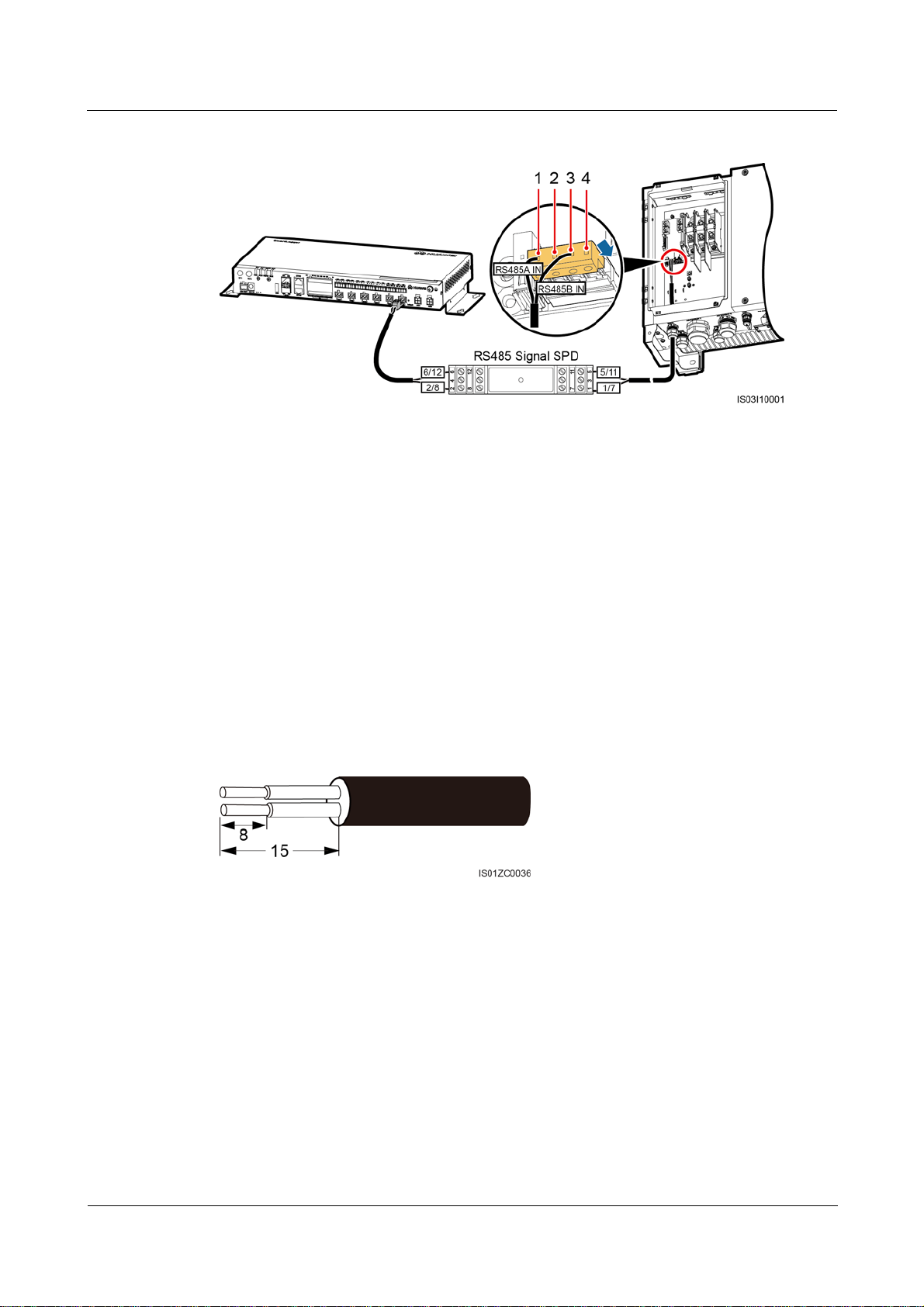
Figure 4-17 shows how to connect the SmartLogger to the SUN2000 through an RS485 signal
SPD.
(2016-06-20) Huawei Proprietary and Confidential
Copyright © Huawei Technologies Co., Ltd.
48
SmartLogger2000
User Manual 4 Connecting Cables
Figure 4-17 Connecting the SmartLogger to the SUN2000
(1) RS485A IN (2) RS485A OUT (3) RS485B IN (4) RS485B OUT
Procedure
Step 1 Prepare a cable with an appropriate length, strip a proper part of the insulation layer from one
end, and connect the end to the SUN2000 terminal block.
The DJYP2VP2-22 2x2x1 network cable or a communications cable with a cross
sectional area of 1 mm
For details about how to strip and connect the wires, see SUN2000-(50KTL, 50KTL-C1)
2
and outer diameter of 14–18 mm is recommended.
User Manual.
Step 2 Remove an appropriate length of the steel armor and wire insulation layer from the other end
of the cable using a wire stripper, as shown in Figure 4-18.
Figure 4-18 Stripping an RS485 communications cable (unit: mm)
Step 3 Insert the bare cable cores into the Surge port of the RS485 signal SPD, as shown by (1) in
Figure 4-19.
(2016-06-20) Huawei Proprietary and Confidential
Copyright © Huawei Technologies Co., Ltd.
49

SmartLogger2000
User Manual 4 Connecting Cables
Figure 4-19 Connecting the Surge port of the RS485 signal SPD
Verify that the RS485A (IN) port on the SUN2000 is connected to Surge port 1 or 7 on the
RS485 signal SPD, and that the RS485B (IN) port on the SUN2000 is connected to Surge
port 5 or 11 on the RS485 signal SPD.
Step 4 Use a flat-head screwdriver to tighten the screws on the Surge ports, as shown by (2) in
Figure 4-19.
Step 5 Set Baud Rate to the same value for the SUN2000 and SmartLogger.
For details about the communications parameters settings for the SmartLogger, see
Setting RS485 Parameters or SUN2000 APP User Manual.
For details about the communications parameters settings for the SUN2000, see
SUN2000 APP User Manual.
----End
Follow-up Procedure
Disconnection can be performed in reverse order.
Connecting the SUN2000 Through an AC Power Cable
Context
The SmartLogger is integrated with the PLC central coordinator (CCO) that can work with
the SUN2000 integrated with the PLC station (STA) to implement power line communication
(PLC) networking over power cables.
Procedure
Step 1 Connect one end of the delivered AC power cable to an MCB.
Step 2 Connect the AC1 and AC2 terminals at the other end of the cable to the AC1 and AC2 ports
on the SmartLogger respectively, as shown in Figure 4-20.
(2016-06-20) Huawei Proprietary and Confidential
Copyright © Huawei Technologies Co., Ltd.
50

SmartLogger2000
User Manual 4 Connecting Cables
Figure 4-20 Connecting an AC power cable to the SmartLogger
Table 4-6 describes the components shown in Figure 4-20.
Table 4-6 Component
No. Component Item Quantity
1 Busbar A/B/C - 1 PCS
2 Fuse Rated voltage: ≥ 500 V; rated current: 6 A 3 PCS
3 Knife switch
box
4 MCB Rated voltage: ≥ 500 V; rated current: ≥
Rated voltage: ≥ 500 V; rated current: ≥
6 A; number of phases: three
1 PCS
1 PCS
6 A
Each SmartLogger can be connected to a maximum of 80 SUN2000s.
If the SmartLogger is connected to the SUN2000 through an AC power cable, no RS485
communications cable needs to be connected.
After connecting cables, log in to the WebUI and enable the PLC function in the SmartLogger. For
details, see Connecting a Device. PLC describes how to configure PLC parameters for the
SmartLogger.
The port used for PLC networking is RS485-0. The recommended Baud Rate for the port is 115200
bit/s, which can provide optimal communications performance.
(2016-06-20) Huawei Proprietary and Confidential
Copyright © Huawei Technologies Co., Ltd.
51

SmartLogger2000
User Manual 4 Connecting Cables
----End
Follow-up Procedure
Disconnection can be performed in reverse order.
4.4.2 Connecting the SUN8000
Context
Figure 4-21 shows the wiring terminals of the RS485 ports of the SUN8000.
Figure 4-21 RS485 wiring terminals for the SUN8000
Ports 07, 08, 09, 10, 11, and 12 are communications ports. Table 4-7 describes the functions
of these ports.
Table 4-7 Port description
No. Function Description
07 S485A RS485A, RS485 differential signal + (reserved)
08 S485B RS485B, RS485 differential signal - (reserved)
09 N485A_OUT RS485A, RS485 differential signal +
10 N485A_IN RS485A, RS485 differential signal +
11 N485B_OUT RS485B, RS485 differential signal -
12 N485B_IN RS485B, RS485 differential signal -
There are six RS485 ports in the SmartLogger. For the port descriptions, see Context in
Connecting the SUN2000 Using an RS485 Communications Cable of 4.4.1 Connecting the
SUN2000.
Figure 4-22 shows how to connect the SmartLogger to the SUN8000 through an RS485 signal
SPD.
(2016-06-20) Huawei Proprietary and Confidential
Copyright © Huawei Technologies Co., Ltd.
52

SmartLogger2000
User Manual 4 Connecting Cables
Figure 4-22 Connecting the SmartLogger to the SUN8000
Procedure
Step 1 Configure a shielded network cable with an appropriate length. Connect two core wires of the
Step 2 Remove 15 mm of the insulation layer from the dual-core shielded cable using a wire stripper.
Step 3 Remove 8 mm of the insulation layer from the two core wires using the wire stripper.
Step 4 Insert the bare cable cores into the Surge port of the RS485 signal SPD, as shown by (1) in
cable to the N485A_IN and N485B_IN ports of the RS485 port for the SUN8000.
Recommended communications cable: dual-core shielded network cable (outdoor
shielded network cables are also acceptable, if only two core wires are connected).
For details about connecting the RS485 ports for the SUN8000, see the
SUN8000-500KTL User Manual.
Figure 4-23.
Figure 4-23 Connecting the Surge port of the RS485 signal SPD
(2016-06-20) Huawei Proprietary and Confidential
Copyright © Huawei Technologies Co., Ltd.
53

SmartLogger2000
User Manual 4 Connecting Cables
Verify that the N485A_IN port on the SUN8000 is connected to Surge port 1 or 7 on the
RS485 signal SPD, and that the N485B_IN port on the SUN8000 is connected to Surge port 5
or 11 on the RS485 signal SPD.
Step 5 Use a flat-head screwdriver to tighten the screws on the Surge ports, as shown by (2) in
Figure 4-23.
Step 6 Set Baud Rate for the SUN8000 to the same Baud Rate configured for the SmartLogger.
For details about the communications parameters settings for the SmartLogger, see
Setting RS485 Parameters or SUN2000 APP User Manual.
For details about the communications parameters settings for the SUN8000, see
SUN8000-500KTL User Manual.
----End
Follow-up Procedure
Take operations in reversed order to disconnect the SmartLogger from the SUN8000.
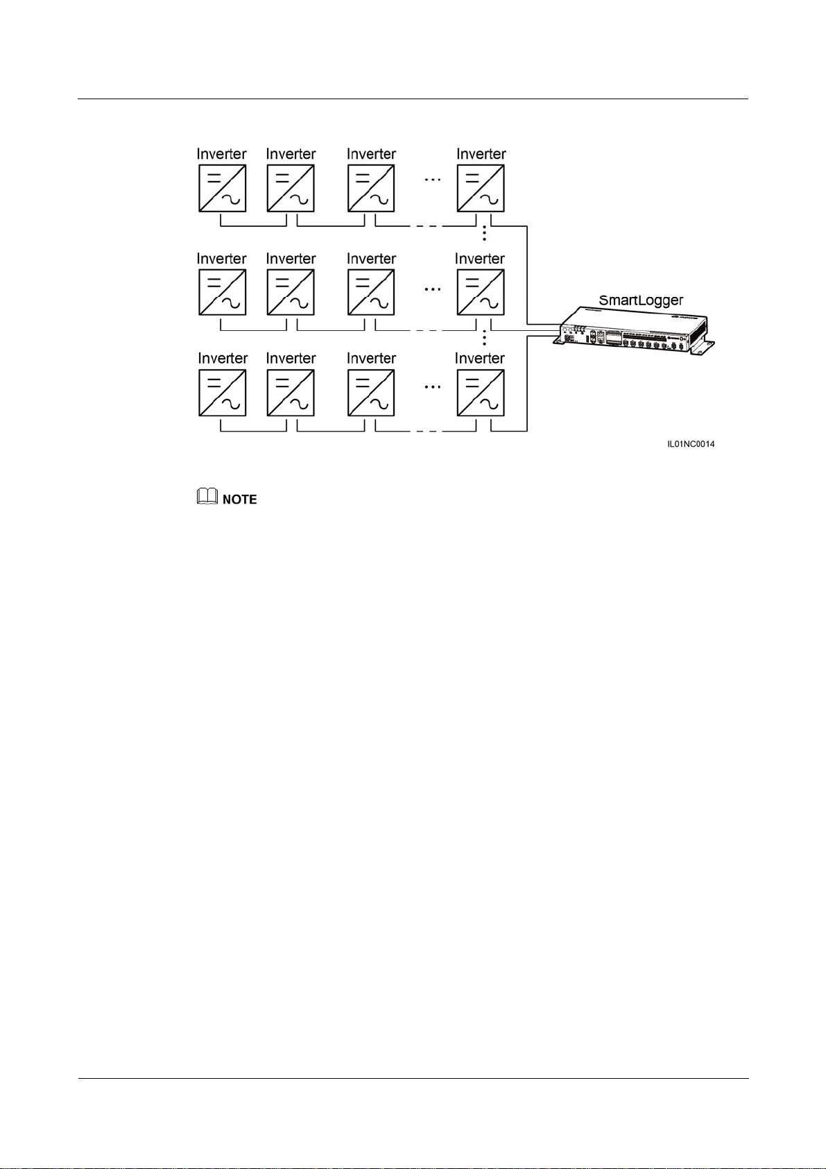
4.4.3 Connecting Multiple Inverters to the SmartLogger
The SmartLogger can connect to multiple inverters through a daisy chain or an AC power
cable.
Daisy Chain Connection
In the daisy chain connection mode, the RS485OUT of one inverter is connected to the
RS485IN port of the next inverter, and the first inverter is connected to the SmartLogger as
described in Connecting the SUN2000 Using an RS485 Communications Cable or 4.4.2
Connecting the SUN8000 in 4.4.1 Connecting the SUN2000. Figure 4-24 shows the
connection.
(2016-06-20) Huawei Proprietary and Confidential
Copyright © Huawei Technologies Co., Ltd.
54
SmartLogger2000
User Manual 4 Connecting Cables
Figure 4-24 Connecting the SmartLogger to multiple inverters
A maximum of 200 devices can be connected to one SmartLogger. You are advised to connect fewer
than 30 devices to each RS485 route. Each SmartLogger can be connected to a maximum of 80
inverters.
If an EMI is to be connected, connect it at the end of the chain.
Set Build-out Resistor to Enable under Comm. Param. for the inverter at the end of each daisy
chain. For details, see SUN2000 APP User Manual.
The addresses for all devices in the daisy chain should be within the searching scope set in the
SmartLogger and they must differ from each other. Otherwise, the communications would fail
between the device and the SmartLogger.
You can perform the Assign Address operation on the built-in WebUI of the SmartLogger. If an
RS485 address conflict is detected for inverters, the SmartLogger automatically reassigns the
addresses without the need for local address upgrade for the inverters.
Baud rate of all the devices in one daisy chain should stay consistent with those of the
SmartLogger.
AC Power Cable Connection
Figure 4-25 shows the method for connecting the SmartLogger to multiple SUN2000s over an
AC power cable.
(2016-06-20) Huawei Proprietary and Confidential
Copyright © Huawei Technologies Co., Ltd.
55

SmartLogger2000
User Manual 4 Connecting Cables
Figure 4-25 PLC networking
Only PLC models of the SUN2000s can be connected to the SmartLogger over an AC power cable.
4.5 Connecting an EMI
Context
The SmartLogger can be connected to an EMI that supports the standard Modbus-RTU
protocol. One SmartLogger can be connected to and manage only one EMI.
Devices from different vendors may support different protocols. To obtain information from
the connected EMI, correctly configure the protocol on the WebUI of the SmartLogger based
on the document delivered by the vendor.
For the definition of the RS485 communications cable for the EMI, see the instructions
delivered with the EMI.
There are six RS485 ports in the SmartLogger. For the port descriptions, see Context in
Connecting the SUN2000 Using an RS485 Communications Cable of 4.4.1 Connecting the
SUN2000.
Figure 4-26 shows how to connect the SmartLogger to an EMI through an RS485 signal SPD.
(2016-06-20) Huawei Proprietary and Confidential
Copyright © Huawei Technologies Co., Ltd.
56

SmartLogger2000
User Manual 4 Connecting Cables
Figure 4-26 Connecting the SmartLogger to the EMI
Procedure
Step 1 Connect one end of the cable delivered with the EMI to the RS485 port of the EMI.
Step 2 Connect the other end of the cable to a Surge port of the RS485 signal SPD. For details, see
Step 2–Step 4 in Procedure in Connecting the SUN2000 Using an RS485 Communications
Cable of 4.4.1 Connecting the SUN2000.
Verify that the RS485+ port on the EMI is connected to Surge port 1 or 7 on the RS485 signal
SPD, and that the RS485- port on the EMI is connected to Surge port 5 or 11 on the RS485
signal SPD.
After connecting the cable, log in to the WebUI and set parameters under EMI. For details about this
operation, see Setting EMI Parameters.
The EMI cannot be detected automatically. You need to add this device manually. For details about
this operation, see Connecting a Device.
If the SmartLogger needs to be connected to an EMI and multiple inverters, connect the EMI at the
end of the daisy chain, and verify that the port connecting to the EMI has a unique communications
address. For details about the daisy chain connections, see Daisy Chain Connection in 4.4.3
Connecting Multiple Inverters to the SmartLogger.
----End
Follow-up Procedure
Take the reverse steps to disconnect the SmartLogger from the EMI.
(2016-06-20) Huawei Proprietary and Confidential
Copyright © Huawei Technologies Co., Ltd.
57
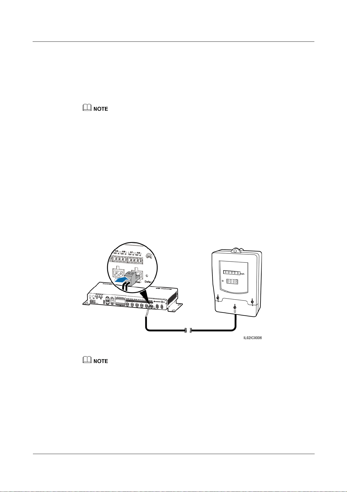
SmartLogger2000
User Manual 4 Connecting Cables
4.6 Connecting a Power Meter
Context
The SmartLogger can be connected to a power meter that supports the standard Modbus-RTU
or DL/T645 protocol.
The SmartLogger can be connected to and manage only one power meter that supports the
Modbus-RTU protocol.
The SmartLogger can be connected to and manage multiple power meters that support the DL/T645
protocol.
The protocol points for Power Meters provided by different vendors are varied. Therefore, to
obtain information from a Power Meter, configure the protocol point on the WebUI of the
SmartLogger properly based on the document delivered by the vendor.
For details about the definition of the RS485 communications cables for the Power Meter, see
the operation manual delivered with the Power Meter.
There are six RS485 ports in the SmartLogger. For the port descriptions, see Context in
Connecting the SUN2000 Using an RS485 Communications Cable of 4.4.1 Connecting the
SUN2000.
Figure 4-27 shows how to connect the SmartLogger to a power meter.
Figure 4-27 Connecting a Power Meter
A power meter is typically installed indoors, and can be connected to the COM port of the SmartLogger
without an RS485 signal SPD.
Procedure
Step 1 Connect one end of the cable delivered with the power meter to the RS485 port of the power
meter.
Step 2 Connect the other end of the cable to the COM port of the SmartLogger. For details about the
operation, see Step 1–Step 5 in 4.3 Connecting the RS485 signal SPD.
(2016-06-20) Huawei Proprietary and Confidential
Copyright © Huawei Technologies Co., Ltd.
58

SmartLogger2000
User Manual 4 Connecting Cables
After connecting the cable for a power meter that supports the Modbus-RTU protocol, log in to the
WebUI and set parameters under Modbus Power Meter. For details, see Setting Power Meter
Parameters.
The communications protocol configured for devices connected to the same SmartLogger COM port
must be the same. After connecting the cable, log in to the WebUI and modify the COM port
protocol. For details, see Setting RS485 Parameters.
A power meter cannot be detected automatically. You need to add this device manually. For details,
see Connecting a Device.
After modifying the protocol for a DL/T645 power meter and adding it manually, log in to the
WebUI to query and set parameters under DL/T645 Power Meter.
----End
Follow-up Procedure
Take operations in reversed order to disconnect the SmartLogger from the Power Meter.
4.7 Connecting the Box-type Transformer
Context
The SmartLogger can be connected to a box-type transformer over the RS485 and Ethernet
communication modes.
The SmartLogger provides two Ethernet electrical ports. A box-type transformer that supports Ethernet
communication can be connected to the SmartLogger through an Ethernet electrical port, and then to an
NMS through the northbound interface of the SmartLogger. In this connection mode, the IP addresses of
the SmartLogger and the box-type transformer must be in the same network segment.
This section describes how to connect a box-type transformer that supports the Modbus-RTU
or IEC103 protocol to the SmartLogger using the RS485 communication mode.
Devices from different vendors may support different protocols. To obtain information from
the connected box-type transformer, correctly configure the protocol on the WebUI of the
SmartLogger based on the document delivered by the vendor.
For the definition of the RS485 communications cable for the box-type transformer, see the
delivered operation guide.
There are six RS485 ports in the SmartLogger. For the port descriptions, see Context in
Connecting the SUN2000 Using an RS485 Communications Cable of 4.4.1 Connecting the
SUN2000.
Figure 4-28 shows how to connect the SmartLogger to the box-type transformer through an
RS485 signal SPD.
(2016-06-20) Huawei Proprietary and Confidential
Copyright © Huawei Technologies Co., Ltd.
59
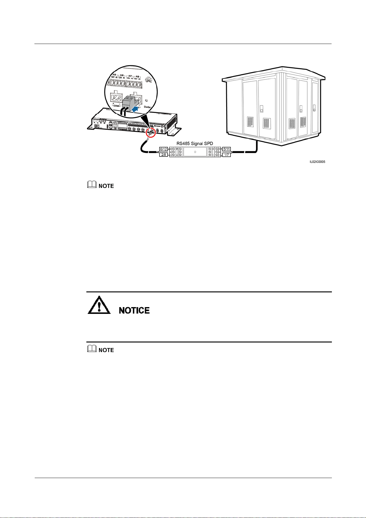
SmartLogger2000
User Manual 4 Connecting Cables
Figure 4-28 Connecting the SmartLogger to the box-type transformer
If the SmartLogger is installed inside the box-type transformer, connect the box-type transformer to the
SmartLogger COM port that has no RS485 signal SPD. For details about how to connect cables at the
SmartLogger side in this scenario, see Step 1–Step 5 in 4.3 Connecting the RS485 signal SPD.
Procedure
Step 1 Connect one end of the cable delivered with the box-type transformer to the RS485 port of the
Step 2 Connect the other end of the cable to a Surge port of the RS485 signal SPD. For details, see
box-type transformer.
Step 3–Step 4 in Connecting the SUN2000 Using an RS485 Communications Cable of 4.4.1
Connecting the SUN2000.
Verify that the RS485+ port on the box-type transformer is connected to Surge port 1 or 7 on
the RS485 signal SPD, and that the RS485- port on the box-type transformer is connected to
Surge port 5 or 11 on the RS485 signal SPD.
The communications protocol configured for devices connected to the same SmartLogger COM port
must be the same.
After connecting the cable, log in to the WebUI and set parameters under Box-type Transformer.
For details about this operation, see Custom Devices.
----End
Follow-up Procedure
Disconnection can be performed in reverse order.
(2016-06-20) Huawei Proprietary and Confidential
Copyright © Huawei Technologies Co., Ltd.
60

SmartLogger2000
User Manual 4 Connecting Cables
4.8 Connecting a PID Module
Context
The PID module is used to prevent PV module output power degradation due to the potential
induced degradation (PID) effect in a PV power system.
The SmartLogger can be connected to and manage only one PID module that supports the
Modbus-RTU protocol.
For the definition of the RS485 communications cable for the PID module, see the delivered
operation guide.
There are six RS485 ports in the SmartLogger. For the port descriptions, see Context in
Connecting the SUN2000 Using an RS485 Communications Cable of 4.4.1 Connecting the
SUN2000.
Figure 4-29 shows how to connect the SmartLogger to the PID module.
Figure 4-29 Connecting the SmartLogger to the PID module
For a smart array controller, the SmartLogger and PID module are installed before delivery, and the PID
module is connected to the SmartLogger through the X2 terminal block.
Procedure
Step 1 Connect one end of the cable delivered with the PID module to the RS485 port of the PID
module.
Step 2 Connect the other end of the cable to the COM port of the SmartLogger. For details about the
operation, see Step 1–Step 5 in 4.3 Connecting the RS485 signal SPD.
(2016-06-20) Huawei Proprietary and Confidential
Copyright © Huawei Technologies Co., Ltd.
61

SmartLogger2000
User Manual 4 Connecting Cables
Verify that the brown cable (RS485A) of the PID module is connected to Surge port 1 or 7 on
the RS485 signal SPD, and that the black cable (RS485B) is connected to Surge port 5 or 11
on the RS485 signal SPD.
Step 3 Set Baud Rate for the PID module to the same Baud Rate configured for the SmartLogger.
The baud rates supported by the PID module include 4800 bit/s, 9600 bit/s, 19200 bit/s, and 115200
bit/s.
The PID module supports automatic address allocation. After connecting cables, log in to the WebUI
and search for the PID module in the Connect Device > Auto. Search menu.
For details about PID parameter settings, see PID.
The default RS485 communications address of the PID module is 1. To change the RS485
communications address, log in to the WebUI and follow instructs in Connecting a Device.
----End
Follow-up Procedure
Take the reverse steps to disconnect the SmartLogger from the PID module.
4.9 Connecting a Ripple Control Receiver
Context
In Germany and some other European areas, a Ripple Control Receiver is used to convert a
power grid scheduling signal to a dry contact signal, in which a dry contact is needed.
Figure 4-30 shows the DI ports of the SmartLogger.
Figure 4-30 DI ports of the SmartLogger
Table 4-8 describes the DI ports.
(2016-06-20) Huawei Proprietary and Confidential
Copyright © Huawei Technologies Co., Ltd.
62

SmartLogger2000
User Manual 4 Connecting Cables
Table 4-8 DI port description
Port Function
GND1
Dry contact input common terminal 1, used for active power derating for
DI1–DI4
DI1 DI_1
DI2 DI_2
DI3 DI_3
DI4 DI_4
DI5 DI_5
DI6 DI_6
DI7 DI_7
DI8 DI_8
GND2 Dry contact input common terminal 2, used for reactive power
compensation for DI5–DI8
DI1–DI4 involve active power deration, and DI5–DI8 involve reactive power compensation.
Figure 4-31 shows how to connect the SmartLogger to a Ripple Control Receiver.
Procedure
Step 1 Select a cable of appropriate length and connect one end of the cable to the Ripple Control
Figure 4-31 Connecting a Ripple Control Receiver
Receiver.
A two-core or multiple-core cable with a cross sectional area of 1.5 mm
2
is recommended.
(2016-06-20) Huawei Proprietary and Confidential
Copyright © Huawei Technologies Co., Ltd.
63

SmartLogger2000
User Manual 4 Connecting Cables
Step 2 Strip 8 mm of the insulation layer at the other end.
Step 3 Remove the terminal block from the SmartLogger DI port.
Remove the terminal block using a flat-head screwdriver.
Step 4 Insert the bare cable cores into the terminal block, as shown by (1) in Figure 4-32.
Figure 4-32 Cable connection for the terminal block
Step 5 Use a flat-head screwdriver to tighten the screws on the terminal block, as shown by (2) in
Figure 4-32.
Step 6 Insert the terminal block into the SmartLogger DI port, as shown in Figure 4-33.
Figure 4-33 Connecting the terminal block
To enable the power grid scheduling function, you need to set the corresponding parameters
(Active Power Control or Reactive Power Control) on the embedded WebUI after connecting
cables. For details, see Active Power Control or Reactive Power Control.
----End
(2016-06-20) Huawei Proprietary and Confidential
Copyright © Huawei Technologies Co., Ltd.
64

SmartLogger2000
User Manual 4 Connecting Cables
Follow-up Procedure
Disconnection can be performed in reverse order.
4.10 Connecting an Ethernet Network Cable
Context
The SmartLogger provides two Ethernet electrical ports, through which the SmartLogger
can connect to a third-party device.
The SmartLogger can be connected to an Ethernet switch, router, or POE module. It can
also be connected to the Ethernet electrical port of a PC directly or through a hub. Select
the connection device based on the actual networking scenario. For the typical
application scenarios, see Figure 2-6 and Figure 2-8 in 2.4 Typical Networking
Scenarios.
Procedure
Step 1 Connect one end of the delivered network cable to the Ethernet electrical port of a device.
If the delivered cable is too short, pay attention to the following when preparing a cable:
Select CAT 5E or a higher-class shielded network cable.
The cable should not exceed 100 m in length.
Step 2 Connect the other end of the network cable to the ETH1 or ETH2 port of the SmartLogger,
as shown in Figure 4-34.
Figure 4-34 Connecting an Ethernet network cable
A POE module can be connected only to the DATA port of the SmartLogger.
The default IP address of the SmartLogger is 192.168.0.10, the default subnet mask is 255.255.255.0,
and the default gateway is 192.168.0.1.
(2016-06-20) Huawei Proprietary and Confidential
Copyright © Huawei Technologies Co., Ltd.
65

SmartLogger2000
User Manual 4 Connecting Cables
If the SmartLogger is connected to a PC directly or through a hub, the IP addresses of the
SmartLogger and PC must be in the same network segment. For example, if the IP address of the
SmartLogger is 192.168.0.10, the IP address of the PC can be 192.168.0.11. The subnet mask and
the gateway of the PC should be consistent with those of the SmartLogger.
If the SmartLogger is connected to a PC through a networking device (such as a router), the IP
addresses of the SmartLogger and networking device must be in the same network segment. Set the
gateway of the SmartLogger correctly so that it can communicate with the networking device.
To enable communication between the SmartLogger and the NetEco, set the NetEco parameters
properly on the SmartLogger. For details, see Setting NetEco Parameters.
----End
Follow-up Procedure
Disconnection can be performed in reverse order.
4.11 Connecting Optical Fibers
Context
Procedure
Step 1 Insert the optical module into the SFP1 or SFP2 port on the SmartLogger.
Step 2 Connect the two optical fibers delivered with the optical module to the ports on the optical
Step 3 Connect the other end of the optical fiber to the ATB, as shown in Figure 4-35.
The SmartLogger can be connected to devices such as an ATB through optical fibers. You can
select the devices to be connected based on the actual networking scenario. For the typical
application scenarios, see Figure 2-6 and Figure 2-7 in 2.4 Typical Networking Scenarios.
An optical module is optional. An optical module with a transmission speed of 100 Mbps and an
optical fiber length within 12 km is recommended.
When inserting an optical module into the SFP1 port, verify that the side with a handle faces
upwards. When inserting an optical module into the SFP2 port, verify that the side with a handle
faces downwards.
module.
(2016-06-20) Huawei Proprietary and Confidential
Copyright © Huawei Technologies Co., Ltd.
66

SmartLogger2000
User Manual 4 Connecting Cables
Figure 4-35 Connecting an ATB
Step 4 Determine the operating status based on the Ethernet optical port indicators, as shown in
Table 4-9.
Figure 4-36 Ethernet optical port indicators
Table 4-9 Blinking status of the Ethernet optical port indicators
Indicator Status Meaning
(1) Upper port
(2) Lower port
Green steady on and yellow
blinking at short intervals
(0.1s on and 0.1s off)
Green steady on and yellow
off
Green steady on and yellow
blinking slowly (0.1s on and
(2016-06-20) Huawei Proprietary and Confidential
Copyright © Huawei Technologies Co., Ltd.
An optical module has been
inserted into the Ethernet
optical port.
An optical fiber link has
been successfully
established.
Optical fiber communication
is in progress.
67

SmartLogger2000
User Manual 4 Connecting Cables
Indicator Status Meaning
1.9s off)
----End
Follow-up Procedure
Disconnection can be performed in reverse order.
1.
When removing an optical fiber, press down the clip first.
2.
When removing an optical module, press down the handle, and then pull the module outwards.
(2016-06-20) Huawei Proprietary and Confidential
Copyright © Huawei Technologies Co., Ltd.
68

SmartLogger2000
User Manual 5 System Operation
5 System Operation
About This Chapter
5.1 Checking Before Power-On
5.2 Powering On the System
5.1 Checking Before Power-On
Table 5-1 lists the items to be checked before the SmartLogger is powered on.
Table 5-1 Items to be checked for the SmartLogger before power-on
No. Check Item Check Result
1 The SmartLogger and RS485 signal SPDs are installed
correctly and securely.
2 Ground cables of the SmartLogger and RS485 signal
SPDs are connected to ground points securely.
3 The cables between the SmartLogger and the RS485
signal SPDs are securely connected.
4 The RS485 communications cable is securely and reliably
connected.
5 The AC power cable is securely connected to the
SmartLogger when the PLC communication is used.
6 Ports not used (such as the RF1, RF2, optical port, and
Ethernet port) are protected by dustproof plugs.
□ Compliant □
Incompliant
□ Compliant □
Incompliant
□ Compliant □
Incompliant
□ Compliant □
Incompliant
□ Compliant □
Incompliant
□ Compliant □
Incompliant
7 Routing for the power cable and signal cable meets the
requirements for routing strong-current and weak-current
cables and complies with the cable routing plan.
8 Cables are bound neatly, and cable ties are secured evenly
and properly in the same direction.
(2016-06-20) Huawei Proprietary and Confidential
Copyright © Huawei Technologies Co., Ltd.
□ Compliant □
Incompliant
□ Compliant □
Incompliant
69
SmartLogger2000
User Manual 5 System Operation
No. Check Item Check Result
9 There is no unnecessary adhesive tape or cable tie on
cables.
5.2 Powering On the System
Prerequisites
You have performed 5.1 Checking Before Power-On.
1. When powering on the system, use the power adapter delivered with the product. The
rated input of the power adapter is 100–240 V AC, 50 Hz or 60 Hz. If adapters of other
models are used, the equipment may be damaged.
Select an AC socket that matches the power adapter.
□ Compliant □
Incompliant
Context
Procedure
Step 1 Insert the output terminal of the power adapter into the 12V IN port of the SmartLogger.
Step 2 Insert the power cable into the power adapter.
Step 3 Insert the power cable plug into an AC socket.
For a smart array controller, the SmartLogger is installed before delivery, and the power cable
is connected.
If the SmartLogger is installed outside a smart array controller, place the power adapter on the
top of the SmartLogger and secure the power adapter using cable ties, as shown in Figure 5-1.
(2016-06-20) Huawei Proprietary and Confidential
Copyright © Huawei Technologies Co., Ltd.
70

SmartLogger2000
User Manual 5 System Operation
Figure 5-1 Connecting the power cable if the SmartLogger is installed outside a smart array
controller
Step 4 Switch on the circuit breaker of the AC socket.
Step 5 Switch on the upstream circuit breaker of the AC power cable.
Step 5 needs to be performed only in the PLC networking scenario.
----End
(2016-06-20) Huawei Proprietary and Confidential
Copyright © Huawei Technologies Co., Ltd.
71

SmartLogger2000
User Manual 6 User Interface
6 User Interface
About This Chapter
6.1 USB Flash Drive Operations
6.2 NMS Operations
6.3 APP Operations
6.1 USB Flash Drive Operations
6.1.1 Exporting Data
Context
USB flash drives of SanDisk, Netac, and Kingston are recommended. Other brands may be
incompatible.
By exporting data, you can obtain data of active alarms, historical alarms, performance,
exception takeover logs, commissioning logs, operation logs, fault information file, and
electronic labels.
Procedure
Step 1 Insert the USB flash drive into the USB port at the bottom of the SmartLogger.
Step 2 Log in to the APP, and choose More > System Maintenance > Generate Local Maint.
Script on the main menu page. For details, see SUN2000 APP User Manual.
The generated boot script file is automatically saved in the root directory of the USB flash drive.
Step 3 Remove the USB flash drive from the USB port at the bottom of the SmartLogger, and insert
the USB flash drive into the port again.
After the USB flash drive is connected again, the SmartLogger can automatically detect the boot script
file.
(2016-06-20) Huawei Proprietary and Confidential
Copyright © Huawei Technologies Co., Ltd.
72

SmartLogger2000
User Manual 6 User Interface
Step 4 The SmartLogger automatically executes all commands specified in the boot script file. View
the LED indicator to determine the operating status.
Verify that the USB flash drive contains a boot script file; otherwise, the SmartLogger
cannot execute the operations.
If SmartLoggers have the same APP login password, the boot script file generated by one
SmartLogger can be used in other SmartLoggers.
The initial APP login password of the SmartLogger is 00000a. Change it upon the first
login.
Table 6-1 Indicator status
Indicator (Silk Screen) Status Meaning
ALM Off No local maintenance is
underway.
----End
6.1.2 Exporting All Files
Context
USB flash drives of SanDisk, Netac, and Kingston are recommended. Other brands may be
incompatible.
If the SmartLogger needs to be replaced, you can export the files before the replacement and then
import the files into the new SmartLogger to ensure data integrity.
After exporting all files, you can view information about the SmartLogger and devices connected to
the SmartLogger.
Blinking green at long
intervals (on for 1s and then
Local maintenance is in
progress.
off for 1s)
Steady green Local maintenance
succeeds.
Blinking green at short
Local maintenance fails.
intervals (on for 0.125s and
then off for 0.125s)
Procedure
Step 1 Insert the USB flash drive into the USB port at the bottom of the SmartLogger.
(2016-06-20) Huawei Proprietary and Confidential
Copyright © Huawei Technologies Co., Ltd.
73

SmartLogger2000
User Manual 6 User Interface
Step 2 Log in to the APP, and choose More > System Maintenance > Generate Local Maint.
Script on the main menu page. For details, see SUN2000 APP User Manual.
The generated boot script file is automatically saved in the root directory of the USB flash drive.
Step 3 Remove the USB flash drive from the USB port at the bottom of the SmartLogger, and insert
the USB flash drive into the port again.
After the USB flash drive is connected again, the SmartLogger can automatically detect the boot script
file.
Step 4 The SmartLogger automatically executes all commands specified in the boot script file. View
the LED indicator to determine the operating status.
Verify that the USB flash drive contains a boot script file; otherwise, the SmartLogger
cannot execute the operations.
If SmartLoggers have the same APP login password, the boot script file generated by one
SmartLogger can be used in other SmartLoggers.
The initial APP login password of the SmartLogger is 00000a. Change it upon the first
login.
Table 6-2 Indicator status
Indicator (Silk Screen) Status Meaning
ALM Off No local maintenance is
----End
6.1.3 Importing All Files
underway.
Blinking green at long
intervals (on for 1s and then
Local maintenance is in
progress.
off for 1s)
Steady green Local maintenance
succeeds.
Blinking green at short
Local maintenance fails.
intervals (on for 0.125s and
then off for 0.125s)
Prerequisites
A USB flash drive contains a boot script file and all export files.
(2016-06-20) Huawei Proprietary and Confidential
Copyright © Huawei Technologies Co., Ltd.
74
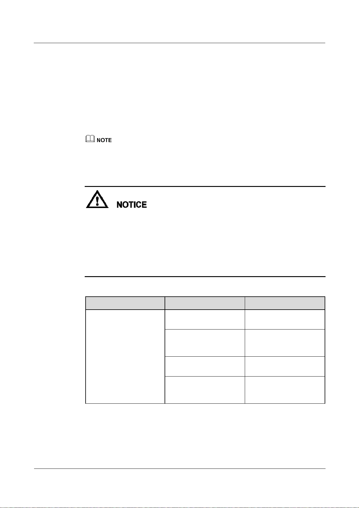
SmartLogger2000
User Manual 6 User Interface
Context
USB flash drives of SanDisk, Netac, and Kingston are recommended. Other brands may be
incompatible.
Procedure
Step 1 Insert the USB flash drive into the USB port at the bottom of the SmartLogger.
Step 2 Log in to the APP, and choose More > System Maintenance > Generate Local Maint.
Script on the main menu page. For details, see SUN2000 APP User Manual.
The generated script file will replace the script file for full file export in the USB flash drive.
Step 3 The SmartLogger automatically executes all commands specified in the boot script file. View
the LED indicator to determine the operating status.
Verify that the USB flash drive contains a boot script file; otherwise, the SmartLogger
cannot execute the operations.
If SmartLoggers have the same APP login password, the boot script file generated by one
SmartLogger can be used in other SmartLoggers. If the SmartLogger to which files are
imported have a different password, you need to generate a new boot script file in the
SmartLogger.
The initial APP login password of the SmartLogger is 00000a. Change it upon the first
login.
Table 6-3 Indicator status
Indicator (Silk Screen) Status Meaning
ALM Off No local maintenance is
underway.
Blinking green at long
intervals (on for 1s and then
Local maintenance is in
progress.
off for 1s)
Steady green Local maintenance
succeeds.
Blinking green at short
Local maintenance fails.
intervals (on for 0.125s and
then off for 0.125s)
----End
(2016-06-20) Huawei Proprietary and Confidential
Copyright © Huawei Technologies Co., Ltd.
75
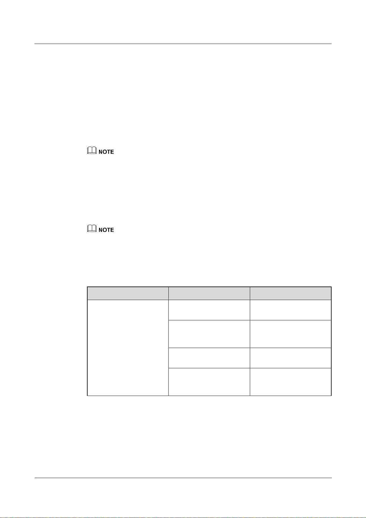
SmartLogger2000
User Manual 6 User Interface
6.1.4 Upgrading the Application
Context
USB flash drives of SanDisk, Netac, and Kingston are recommended. Other brands may be
incompatible.
Procedure
Step 1 Log in to http://support.huawei.com/carrier/, click Product Support, browse to or search for
SmartLogger, and download the required upgrade package on the Software tab.
The upgrade package is named smartlogger2000.zip. Store the upgrade package in the root directory of a
USB flash drive, and do not decompress it.
Step 2 Insert the USB flash drive into the USB port at the bottom of the SmartLogger.
Step 3 Log in to the APP, and choose More > System Maintenance > Generate Local Maint.
Script on the main menu page. For details, see SUN2000 APP User Manual.
Step 4 Replace the boot script file in the upgrade package with the boot script file in the USB flash
drive.
The boot script file in the upgrade package is named logger_lmt_mgr_cmd.emap.
Step 5 Insert the USB flash drive into the USB port at the bottom of the SmartLogger. The
SmartLogger automatically executes all commands specified in the boot script file. View the
LED indicator to determine the operating status.
Table 6-4 Indicator status
Indicator (Silk Screen) Status Meaning
ALM Green off No local maintenance is
underway.
Blinking green at long
intervals (on for 1s and then
Local maintenance is in
progress.
off for 1s)
Steady green Local maintenance
succeeds.
Blinking green at short
Local maintenance fails.
intervals (on for 0.125s and
then off for 0.125s)
Step 6 After the upgrade is complete, the SmartLogger automatically restarts.
----End
(2016-06-20) Huawei Proprietary and Confidential
Copyright © Huawei Technologies Co., Ltd.
76

SmartLogger2000
User Manual 6 User Interface
6.1.5 Upgrading the BSP
Context
USB flash drives of SanDisk, Netac, and Kingston are recommended. Other brands may be
incompatible.
For details about how to upgrade the board support package (BSP), see SmartLogger Upgrade
Guide or contact Huawei technical support.
Procedure
Step 1 Log in to http://support.huawei.com/carrier/, click Product Support, browse to or search for
SmartLogger, and download the required upgrade package on the Software tab.
The upgrade package is named smartlogger2000_bsp.zip. Store the upgrade package in the root
directory of a USB flash drive, and do not decompress it.
Step 2 Insert the USB flash drive into the USB port at the bottom of the SmartLogger.
Step 3 Log in to the APP, and choose More > System Maintenance > Generate Local Maint.
Script on the main menu page. For details, see SUN2000 APP User Manual.
Step 4 Replace the boot script file in the upgrade package with the boot script file in the USB flash
drive.
The boot script file is named logger_lmt_mgr_cmd.emap.
Step 5 Insert the USB flash drive into the USB port at the bottom of the SmartLogger. The
SmartLogger automatically executes all commands specified in the boot script file. View the
LED indicator to determine the operating status.
Table 6-5 Indicator status
Indicator (Silk Screen) Status Meaning
ALM Green off No local maintenance is
underway.
Blinking green at long
intervals (on for 1s and then
Local maintenance is in
progress.
off for 1s)
Steady green Local maintenance
Blinking green at short
intervals (on for 0.125s and
then off for 0.125s)
(2016-06-20) Huawei Proprietary and Confidential
Copyright © Huawei Technologies Co., Ltd.
succeeds.
Local maintenance fails.
77

SmartLogger2000
User Manual 6 User Interface
Step 6 After the upgrade is complete, the SmartLogger automatically restarts.
----End
6.2 NMS Operations
Using the NMS, you can perform firmware upgrade and log export for the SmartLogger. For
details, see NetEco 1000S User Manual.
6.3 APP Operations
Using the APP, you can monitor, query alarms for, and manage the SmartLogger and
southbound devices connected to the SmartLogger. For details, see SUN2000 APP User
Manual.
(2016-06-20) Huawei Proprietary and Confidential
Copyright © Huawei Technologies Co., Ltd.
78

SmartLogger2000
User Manual 7 Maintenance
7 Maintenance
About This Chapter
This topic describes how to perform daily maintenance and troubleshooting to ensure
long-term proper operation of the SmartLogger.
9.1 Daily Maintenance
This topic describes the daily maintenance for the SmartLogger.
9.2 Troubleshooting
9.3 Alarms
7.1 Daily Maintenance
This topic describes the daily maintenance for the SmartLogger.
Check that the SmartLogger is free from strong electromagnetic interference.
Check that the SmartLogger is free from heat sources.
Check that the heat dissipation holes are not blocked.
Clean up the dirt and dust for the SmartLogger periodically.
Check that the cables are secured.
7.2 Troubleshooting
Table 7-1 describes the common faults and the troubleshooting measures for the SmartLogger.
Table 7-1 Common fault list
No. Symptom Possible Cause Measures
1 The
SmartLogg
er cannot
be
powered
(2016-06-20) Huawei Proprietary and Confidential
Copyright © Huawei Technologies Co., Ltd.
1. The DC output power cable
for the power adapter does not
connect to the 12V IN port of
the SmartLogger.
2. The power cable does not
1. Connect the DC output power
cable for the power adapter to
the 12V IN port of the
SmartLogger.
2. Connect the power cable to
79

SmartLogger2000
User Manual 7 Maintenance
No. Symptom Possible Cause Measures
on.
2 Devices
cannot be
searched.
3 The
communic
ation for
PLC
networking
fails.
4 The
communic
ation for
optical
fiber
networking
fails.
5 Devices
Status is
Disconnect
ion on the
SmartLogg
er.
connect to the AC power
receiving port of the power
adapter.
3. The AC input power cable
does not connect to the AC
socket.
4. Power adapter is faulty.
5. The SmartLogger is faulty.
1. The COM port does not
connect to any device, or the
cable is loose, disconnected,
or reversely connected.
2. The communications
parameters for the RS485 port
are incorrect.
3. The devices that cannot be
detected automatically, such
as the EMI and power meter,
are not manually added.
4. The EMI parameters are not
set correctly.
5. The address for the inverter is
not within the search address
segment set for the
SmartLogger.
1. The AC power cable is loose,
disconnected, or reversely
connected.
2. The upstream circuit breaker
for the AC power cable is
OFF.
3. The SmartLogger is faulty.
1. The optical fiber jumper is
loose, disconnected, or
reversely connected.
2. The Ethernet optical port
indicator is faulty.
3. The Ethernet optical port is
faulty.
1. The cable between the device
and the SmartLogger is loose
or disconnected.
2. The device is powered off.
3. The baud rate or RS485
address of the device is
the AC power receiving port
of the power adapter.
3. Connect the power cable to
the AC socket.
4. Replace the power adapter.
5. Contact the vendor or
Huawei technical support.
1. Check the RS485
communications cable
connection. If any cable is
loose, drops off, or is
reversely connected, rectify
the connection.
2. Correctly set the RS485
communications parameters,
and ensure that the baud rate
and the communications
address are correctly set.
3. Manually add the devices that
cannot be detected
automatically, such as the
EMI and power meter.
4. Correctly set the EMI
parameters
5. Set the address of the inverter
to be within the search
address segment set for the
SmartLogger.
1. Reconnect the AC power
cable securely.
2. Switch on the upstream
circuit breaker for the AC
power cable.
3. Contact the vendor or
Huawei technical support.
1. Reconnect the optical fiber
jumper securely.
2. Contact the vendor or
Huawei technical support.
3. Contact the vendor or
Huawei technical support.
1. Verify that the cable between
the device and the
SmartLogger is properly
connected and tightened.
2. Power on the device.
3. Verify the baud rate and
(2016-06-20) Huawei Proprietary and Confidential
Copyright © Huawei Technologies Co., Ltd.
80

SmartLogger2000
User Manual 7 Maintenance
No. Symptom Possible Cause Measures
6 The EMI
cannot be
added.
7 The
SmartLogg
er cannot
communic
ate with
the NetEco
in the PC.
changed.
4. The device is replaced.
5. The device is no longer
connected.
1. The RS485 communications
cable between the EMI and
the SmartLogger is not
properly connected, or the
RS485 communications cable
is loose or disconnected.
2. The EMI is powered off.
3. The baud rate of the EMI is
inconsistent with that of the
SmartLogger.
4. Parameter settings of the EMI
are incorrect.
1. The SmartLogger does not
connect to the PC, or the
cable between the
SmartLogger and the PC is
loose or disconnected.
2. Ethernet parameters are not
properly set.
3. NetEco parameters are not
properly set.
RS485 address of the device.
4. If a device is replaced, search
for or manually add the
device.
5. If the device is removed,
remove the device on the
SmartLogger.
1. Verify that the RS485
communications cable is
properly connected and
tightened.
2. Power on the EMI.
3. Verify the baud rate of the
EMI.
4. Log in to the WebUI and
verify the parameter settings
of the EMI.
1. Verify that the Ethernet
electrical port or optical port
of the SmartLogger correctly
connects to a PC or router.
2. Check that the Ethernet
parameters are correctly set.
3. Check that the NetEco
parameters are correctly set.
7.3 Alarms
Table 7-2 describes the common alarms and the troubleshooting measures for the
SmartLogger.
Table 7-2 Alarms
Alar
m ID
1100 Abnorma
Alarm Alarm
Severit
y
Major 1 Under the
l
P-Contro
l
Alarm
Sub-I
D
Causes Measure
1. Verify that the port
active
power AI
remote
control
mode, the
AI port
receives
corresponding to the AI No. in
use connects to a cable
properly. If the cable is loose,
disconnected, or reversely
connected, reconnect it firmly
and correctly.
2. Enter the active power AI
(2016-06-20) Huawei Proprietary and Confidential
Copyright © Huawei Technologies Co., Ltd.
81

SmartLogger2000
User Manual 7 Maintenance
Alar
Alarm Alarm
m ID
1101 Abnorma
l
Q-Contro
l
Severit
y
Alarm
Sub-I
D
Causes Measure
currents
beyond the
configuratio
n range.
4 Under the
active
power Dry
contact
remote
control
mode, the
four DI
ports read
commands
beyond the
configuratio
n.
Major 1 Under the
reactive
power AI
remote
control
mode, the
AI port
receives
currents
beyond the
configuratio
n range.
4 Under the
reactive
power Dry
contact
remote
control
mode, the
remote control configuration
page and check that the start
and end current ranges of the
AI comply with the
requirements of the power grid
company.
3. Contact the power grid
company to check whether the
command data sent is correct.
1. Check whether the cable
connections to the DI ports are
correct.
2. Enter the active power Dry
contact remote control
configuration page and check
the mapping table of the
current DI signal
configuration. Contact the
power grid company to check
the completeness of the
combination configurations in
the mapping table and check
whether the configurations
comply with the requirements
of the power grid company.
1. Verify that the port
corresponding to the AI No. in
use connects to a cable
properly. If the cable is loose,
disconnected, or reversely
connected, reconnect it firmly
and correctly.
2. Enter the reactive power AI
remote control configuration
page and check that the start
and end current ranges of the
AI comply with the
requirements of the power grid
company.
3. Contact the power grid
company to check whether the
command data sent is correct.
1. Check whether the cable
connections to the DI ports are
correct.
2. Enter the reactive power Dry
contact remote control
configuration page and check
the mapping table of the
(2016-06-20) Huawei Proprietary and Confidential
Copyright © Huawei Technologies Co., Ltd.
82

SmartLogger2000
User Manual 7 Maintenance
Alar
Alarm Alarm
m ID
1103 Breaker
Disconne
ct
1104 Abnorma
l Cubicle
Severit
y
Alarm
Sub-I
D
Causes Measure
four DI
ports read
commands
beyond the
configuratio
n.
Major 1 The general
AC circuit
breaker at
the grid-tied
point is
OFF.
Major 1 The Cubicle
device has
detected an
exception at
the grid-tied
point.
current DI signal
configuration. Contact the
power grid company to check
the completeness of the
combination configurations in
the mapping table and check
whether the configurations
comply with the requirements
of the power grid company.
Check whether the disconnection
of the circuit breaker is a normal
operation. Otherwise, contact the
service engineer to restore the
connection.
When the Cubicle alarm is
enabled, check whether the DI
signal received by the
SmartLogger is consistent with
the dry contact status. If yes,
restart the inverter.
1105 Device
Address
Conflict
Major 1 The
SmartLogge
r RS485
address
conflicts
with the
physical
address
(RS485
address) or
logical
address for
the
connected
southbound
device.
1. If the SmartLogger RS485
address conflicts with the
physical address for the
connected southbound device,
choose Settings > Comm.
Param. > Modbus TCP and
modify SmartLogger
address, or choose
Maintenance > Device
Mgmt. > Connect Device to
change the southbound device
address. If the southbound
device is a SUN2000, you can
change its address on the APP.
2. If the SmartLogger RS485
address conflicts with the
logical address for the
connected southbound device,
choose Settings > Comm.
Param. > Modbus TCP and
modify SmartLogger
address.
(2016-06-20) Huawei Proprietary and Confidential
Copyright © Huawei Technologies Co., Ltd.
83

SmartLogger2000
User Manual 8 Disposing of the SmartLogger
8 Disposing of the SmartLogger
This topic describes how to dispose the SmartLogger.
If the service life of the SmartLogger expires, dispose of the SmartLogger according to the
local disposal act for waste electric appliances. You can also return it to Huawei, with the
related expenses paid.
(2016-06-20) Huawei Proprietary and Confidential
Copyright © Huawei Technologies Co., Ltd.
84

SmartLogger2000
User Manual 9 Certification Declaration
9 Certification Declaration
9.1 CE
Hereby, Huawei Technologies Co., Ltd., declares that this device is in compliance with the
essential requirements and other relevant provisions of Directive 1999/5/EC.
9.2 FCC
This equipment has been tested and found to comply with the limits for a Class B digital
device, pursuant to part 15 of the FCC Rules. These limits are designed to provide reasonable
protection against harmful interference in a residential installation. This equipment generates
uses and can radiate radio frequency energy and, if not installed and used in accordance with
the instructions, may cause harmful interference to radio communications. However, there is
no guarantee that interference will not occur in a particular installation. If this equipment does
cause harmful interference to radio or television reception, which can be determined by
turning the equipment off and on, the user is encouraged to try to correct the interference by
one or more of the following measures:
Reorient or relocate the receiving antenna.
Increase the separation between the equipment and receiver.
Connect the equipment into an outlet on a circuit different from that to which the
receiver is connected.
Consult the dealer or an experienced radio/TV technician for help.
This device complies with FCC radiation exposure limits set forth for an uncontrolled
environment.
This device complies with Part 15 of the FCC Rules. Operation is subject to the following two
conditions: (1) this device may not cause harmful interference, and (2) this device must accept
any interference received, including interference that may cause undesired operation.
Any changes or modifications not expressly approved by the party responsible for compliance
could void the user's authority to operate the equipment.
(2016-06-20) Huawei Proprietary and Confidential
Copyright © Huawei Technologies Co., Ltd.
85
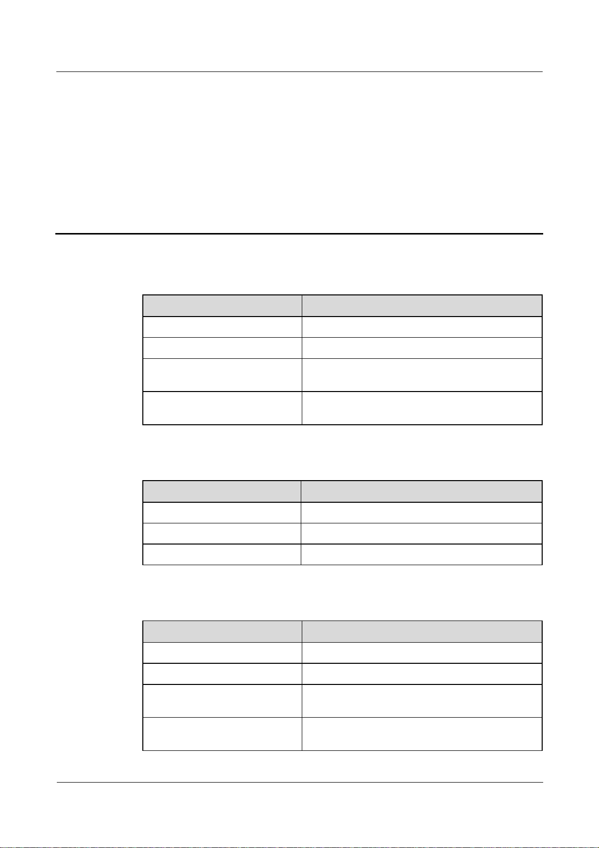
SmartLogger2000
User Manual 10 Technical Specifications
10 Technical Specifications
Device management
Specifications SmartLogger2000
Number of managed devices 200
Number of managed inverters 80
Communications mode Six RS485 ports, two Ethernet electrical ports, two
The maximum communication
distance
Display
Specifications SmartLogger2000
Bluetooth Connected through the SUN2000 APP
LED Four LED indicators
WebUI Embedded
Common parameters
Specifications SmartLogger2000
Ethernet optical ports, and PLC
RS485: 1000 m; Ethernet: 100 m; optical fiber:
12,000 m
Power supply 100–240 V AC, 50 Hz/60 Hz
Power consumption Normal: 8 W; maximum: 15 W
Language English, Chinese, German, Italian, Japanese, French,
and Russian
Dimensions (H x W x D, including
mounting ears)
(2016-06-20) Huawei Proprietary and Confidential
Copyright © Huawei Technologies Co., Ltd.
350 mm x 170 mm x 44 mm
86

SmartLogger2000
User Manual 10 Technical Specifications
Specifications SmartLogger2000
Weight 3800 g
Operating temperature –40ºC to +60ºC
Storage temperature –40ºC to +85ºC
Port
Relative humidity
(non-condensing)
5%-95%
Protection level IP20
Installation mode Installed in Huawei communication box, on a wall, or
on guide rails
Altitude 4000 me
e: When the altitude is between 3000 meters and 4000 meters, the temperature decreases by
1ºC for each additional 200 meters.
Specifications SmartLogger2000
Ethernet electrical port 10/100M
Ethernet optical port 100M
PLC port 1
RS485 6, supported baud rates: 4800 bit/s, 9600 bit/s, 19,200
bit/s, and 115,200 bit/s
USB USB2.0
Digital input 8
Digital output 3
Analog input 8
Analog output 6
(2016-06-20) Huawei Proprietary and Confidential
Copyright © Huawei Technologies Co., Ltd.
87

SmartLogger2000
User Manual A Product User Lists
A Product User Lists
Table A-1 Monitoring user list
Login Mode User Name Initial Password
APP Common User 00000a
Advanced User 00000a
Special User 00000a
WebUI Common User Changeme
Advanced User Changeme
Special User Changeme
NetEco emscomm /EzFp+2%r6@IxSCv
Table A-2 Operating system user list
User Name Initial Password
enspire Changeme
root Changeme
prorunacc No preset password
bin No preset password
daemon No preset password
nobody No preset password
sshd No preset password
(2016-06-20) Huawei Proprietary and Confidential
Copyright © Huawei Technologies Co., Ltd.
88

SmartLogger2000
User Manual B Acronyms and Abbreviations
B Acronyms and Abbreviations
A
AC
AI
AO
APP
C
CCO
COM
D
DI
DO
E
ETH
Alternating Current
Analog Input
Analog Output
Application
Central Coordinator
Communication
Digital Input
Digital Output
Ethernet
L
LED
P
PLC
R
(2016-06-20) Huawei Proprietary and Confidential
Copyright © Huawei Technologies Co., Ltd.
Light-emitting Diode
Power Line Communication
89

SmartLogger2000
User Manual B Acronyms and Abbreviations
RSTP
S
SFP
STA
STP
W
WEEE
Rapid Spanning Tree Protocol
Small Form-factor Pluggable
Station
Spanning Tree Protocol
Waste Electrical and Electronic Equipment
(2016-06-20) Huawei Proprietary and Confidential
Copyright © Huawei Technologies Co., Ltd.
90
 Loading...