

Huawei SmartLogger2000-11-B, SmartLogger2000-10-B, SmartLogger2000-10-C, SmartLogger2000-11-C Quick Manual
Page 1
HUAWEI TECHNOLOGIES CO., LTD.
SmartLogger2000
Quick Guide
Issue: 04
Part number: 31508122
Date: 2018-06-13
Page 2
1
1
Overview
1. The information in this document is subject to change without notice. Every effort has been made
in the preparation of this document to ensure accuracy of the contents. However, all statements,
information, and recommendations in this document do not constitute a warranty of any kind,
express or implied.
2. Before installing the device, carefully read the SmartLogger2000 User Manual to get familiar with
the product information and precautions. SmartLogger is short for SmartLogger2000 in the
following text.
3. Install and use the device according to this document and the user manual. Otherwise, the device
may be damaged. Use insulated tools when installing the device.
4. When the SmartLogger is applied in a non-Huawei smart array controller (smart array controller
for short), install it in the third-party cabinet. This section describes the installation and cable
connection operations using the SmartLogger in non-Huawei smart array controller scenario as
an example.
Copyright © Huawei Technologies Co., Ltd. 2018. All rights reserved.
Model Description
1.1
NOTICE
Model
Description
Model
Description
SmartLogger2000
-10
10: with a built-in 500 V
AC PLC central
coordinator (CCO)
SmartLogger2000
-10-C
10-C: with a built-in
800 V AC PLC
central coordinator
(CCO)
11-C: with no built-
in
PLC CCO
SmartLogger2000
-10-B
10-B: with a built-in
500 V AC PLC
central coordinator
(CCO)
11-B: with no PLC
CCO
S
martLogger2000-11-C
SmartLogger2000
-11-B
N/A
N/A
The SmartLogger with a built-in PLC CCO can work with the SUN2000 integrated with the PLC
station (STA) to implement PLC networking.
If the SmartLogger with no built-in PLC CCO needs to work with the SUN2000 integrated with the
PLC STA to implement PLC networking, an external PLC CCO needs to be connected.
The Bluetooth module embedded in the SmartLogger2000-10 supports only the Android app. The
Bluetooth modules embedded in other models of SmartLoggers support both the Android app
and the iOS app.
This document uses the SmartLogger2000-10-C as an example to describe typical scenarios and
cable connections.
NOTE
Page 3
2
Port Description
1.2
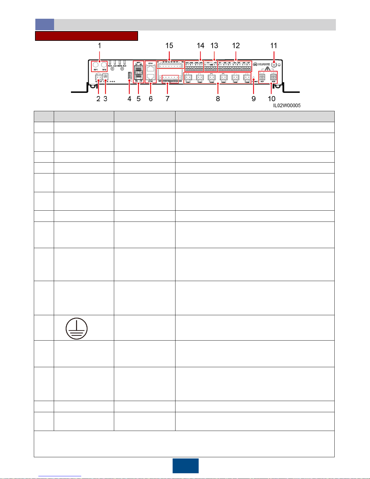
SmartLogger2000-10-C/11-C
No.
Port (Silk Screen)
Function Description
1
RF1, RF2
Reserved
Reserved.
2
12V OUT
12 V DC output
Provides 12 V DC power supply with a maximum
current of 100 mA.
3
12V IN
12 V DC input
Connects to the power adapter.
4
USB
USB port
Connects a USB flash drive.
5
SFP1, SFP2
Ethernet optical port
Connects to an ATB or another cascaded
SmartLogger.
6
ETH1, ETH2
Ethernet electrical
port
Connects to an Ethernet LAN switch, router, POE or
PC device.
7
DO
Digital output (DO)
Relay output supports 12 V voltage and 0.5 A current.
8
COM1
–COM6
RS485
communications
Six RS485 ports that can be connected to devices
such as the SUN2000, box
-type transformer, power
meter, or EMI.
9
Default
Default key
Resets and restarts the Bluetooth module or resets
the SmartLogger IP address to the default IP address
(valid within 5 minutes). The default IP address is
192.168.0.10.
10
AC1, AC2
a
AC power cable
ports
SmartLogger2000
-10-C: Connects to three-
phase (A,
B, and C) inputs
, and is used for PLC with the
SUN2000 over AC power cables.
SmartLogger2000
-11-C: disabled
11
Shell
ground point
N/A
12
AI1
–AI7
Analog input
AI1 supports 0
–10 V input voltage (passiveb); AI2–
AI7
support 0
–20 mA and 4–
20 mA input current (passive).
13
PT1, PT2
Analog input
PT1 supports the connection to a three-wire or twowire PT100/PT1000 temperature sensor.
PT2 supports the connection to only a two-wire
PT100/PT1000 temperature sensor.
14
AO1
–AO4
Analog output (AO)
4
–20 mA and 0–20 mA output current
15
DI1
–DI8
Digital input (DI)
Connects to a dry contact input. GND1 and GND2 are
ground ports for DI signals.
Note a: When the
SmartLogger is applied in a non-smart array controller, connect the AC1 and AC2
ports to the SPD with the delivered cables. The residue voltage of the SPD should be less than 6 kV.
Note b: Passive means that the AI port can connect to a sensor that needs to be energized separately.
Page 4
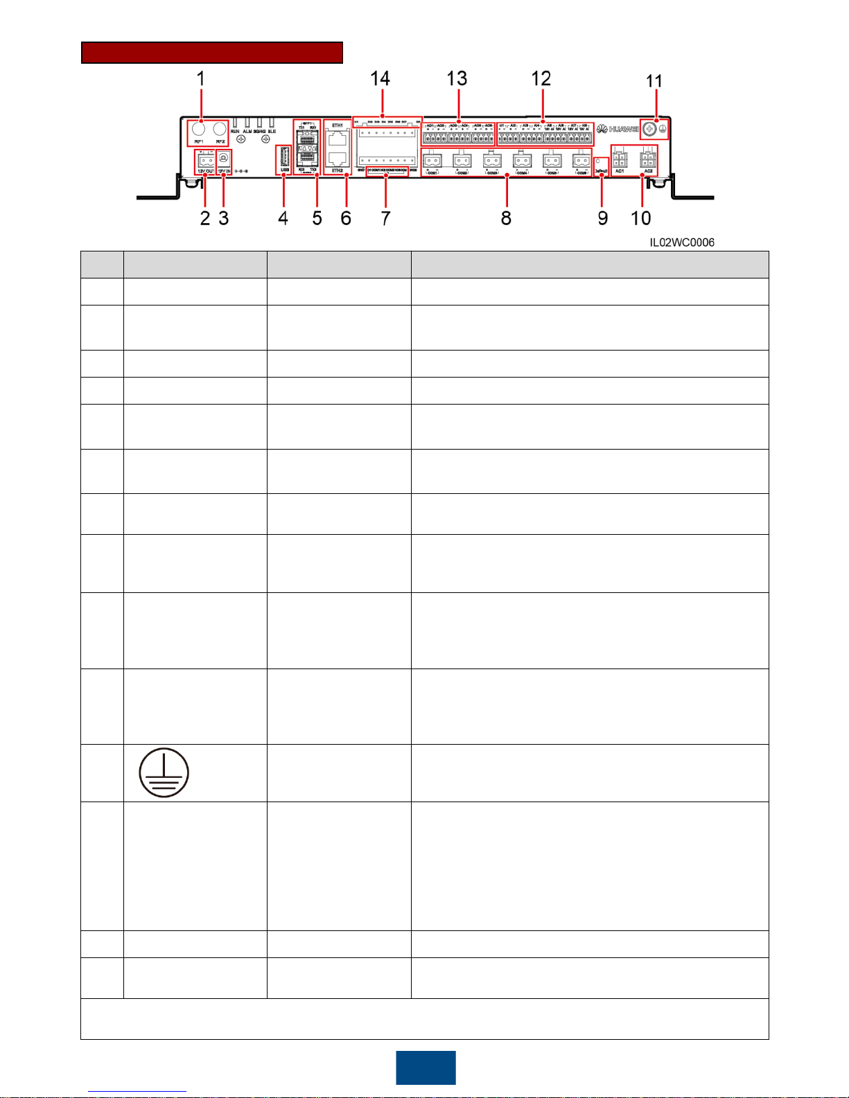
No. Port (Silk Screen) Function Description
1
RF1, RF2
Reserved
Reserved.
2
12V OUT
12 V DC output
Provides 12 V DC power supply with a maximum
current of 100 mA.
3
12V IN
12 V DC input
Connects to the power adapter.
4
USB
USB port
Connects a USB flash drive.
5
SFP1, SFP2
Ethernet optical port
Connects to an ATB or another cascaded
SmartLogger.
6
ETH1, ETH2
Ethernet electrical
port
Connects to an Ethernet LAN switch, router, POE or
PC device.
7
DO
Digital output (DO)
Relay output supports 12 V voltage and 0.5 A current.
8
COM1
–COM6
RS485
communications
Six RS485 ports that can be connected to devices
such as the SUN2000, box
-type transformer, power
meter, or EMI.
9
Default
Default key
Resets and restarts the Bluetooth module or resets
the SmartLogger IP address to the default IP address
(valid within 5 minutes). The default IP address is
192.168.0.10.
10
AC1, AC2
AC power cable
ports
SmartLogger2000-10/10-
B: Connects to the A/B/C
three-phase input, and used for PLC with the
SUN2000 over AC power cables.
SmartLogger2000-11-B: disabled
11
Shell
ground point
N/A
12
AI1
–AI8
Analog input
SmartLogger2000-10: AI1–AI4: 4–20 mA and 0–
20
mA input current (passivea); AI5–AI8: 4–
20 mA and
0–20 mA input current (activeb)
SmartLogger2000-10-B/11-B: AI1: 0–10 V input
voltage (passive); AI2–AI4: 4–20 mA and 0–
20 mA
input current (passive); AI5–AI8: 4–20 mA and 0–
20 mA input current (active)
13
AO1
–AO6
Analog output (AO)
4
–20 mA and 0–20 mA output current
14
DI1
–DI8
Digital input (DI)
Connects to a dry contact input. GND1 and GND2
are ground ports for DI signals.
Note a: Passive means that the AI port can connect to a sensor that needs to be energized separately.
Note b: Active means that the AI port can connect to a sensor that need not be energized separately.
3
SmartLogger2000-10/10-B/11-B
Page 5
4
2
Typical Cable Connection Scenarios
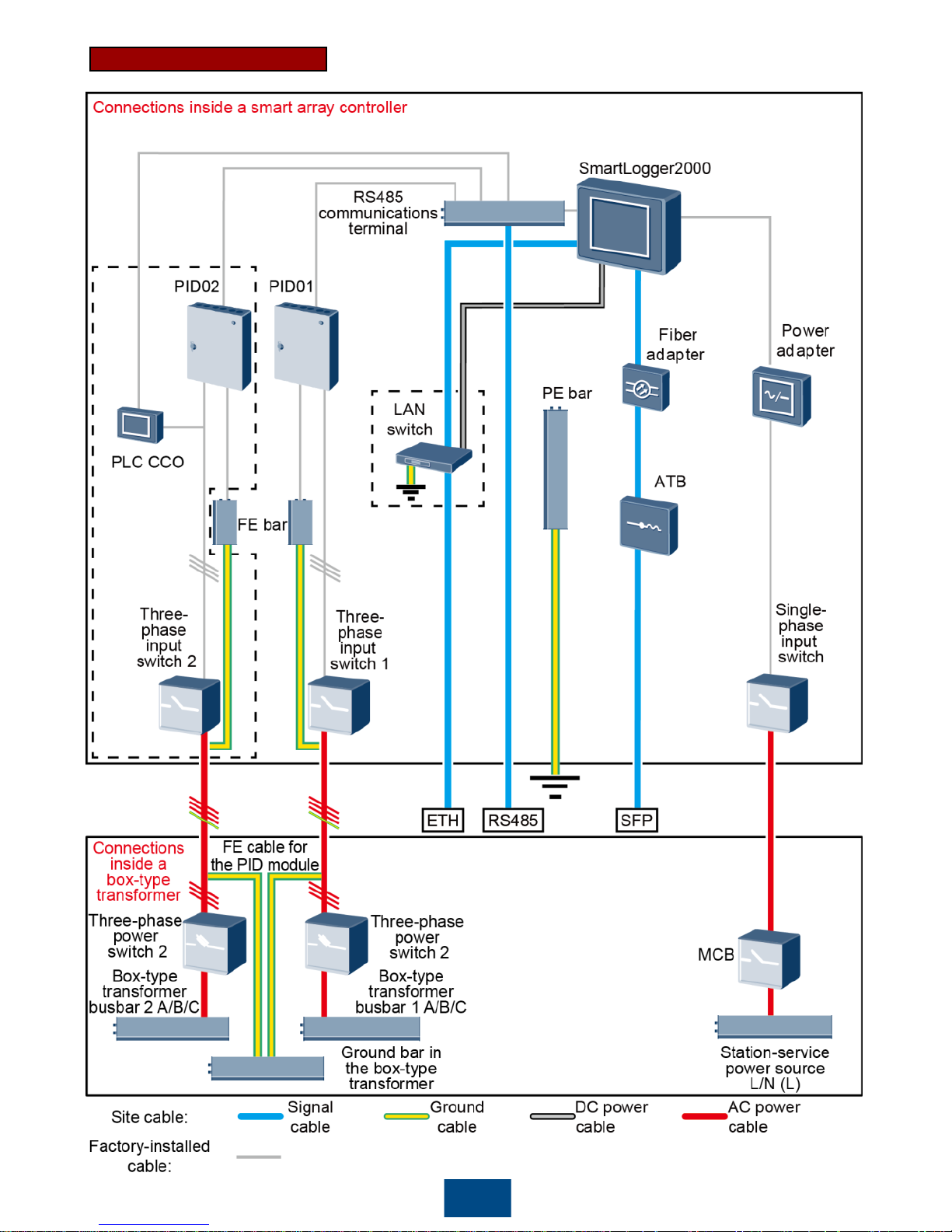
Smart Array Controller Scenario
2.1
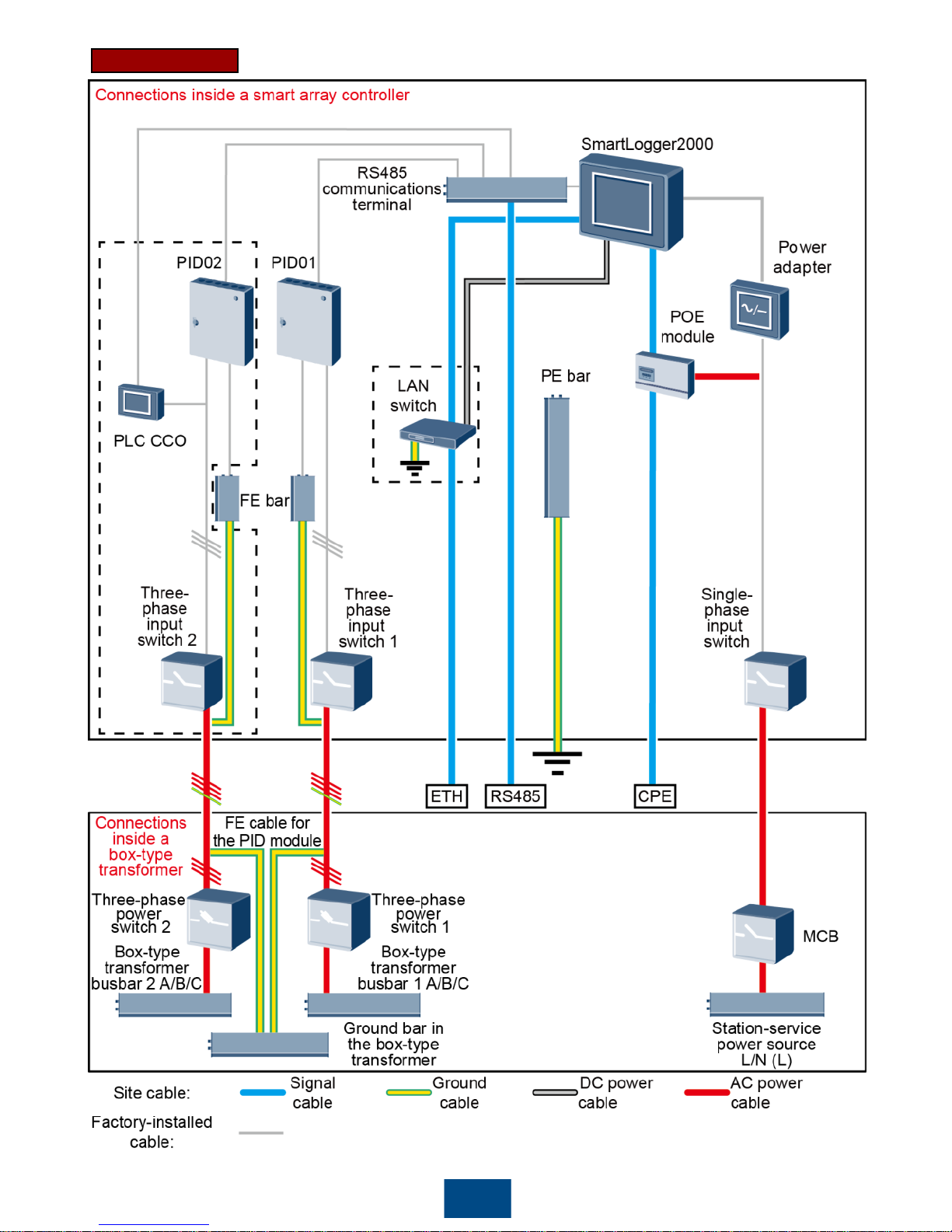
This document describes the application scenario where the SmartLogger is inside the smart
array controller SmartACU2000B-D-2PID/2PLC.
The tables under figures list only the components to be configured by the customer in the
corresponding scenario.
NOTE
NOTICE
1. Prepare the single-phase AC power cable for the smart array controller by yourself.
Recommended: a two-core outdoor armor copper cable with an operating voltage to the ground
greater than or equal to 300 V and a cross-sectional area of 4 mm2for each core wire
2. Prepare the power cable from the miniature circuit breaker (MCB) to the station-service power
source by yourself. Recommended: a two-core outdoor armor copper cable with an operating
voltage to the ground greater than or equal to 300 V and a cross-sectional area of 4 mm2for each
core wire
3. Prepare the three-phase AC power cable for the smart array controller by yourself. Recommended:
a four-core (L1, L2, L3, and functional earthing) outdoor armor copper cable with a cross-sectional
area of 10 mm2for each core wire. When the rated AC voltage on the low-voltage side of the boxtype transformer is less than or equal to 500 V, the operating voltage between the three-phase AC
power cable and the ground should be greater than or equal to 600 V. When the rated AC voltage
on the low-voltage side of the box-type transformer is greater than 500 V and less than or equal to
800 V, the operating voltage between the three-phase AC power cable and the ground should be
greater than or equal to 1000 V.
4. Prepare the power cable from the busbar to the Three-phase power switch by yourself.
Recommended: a four-core (L1, L2, L3, and functional earthing) outdoor armor copper cable with a
cross-sectional area of 10 mm2for each core wire. When the rated AC voltage on the low-voltage
side of the box-type transformer is less than or equal to 500 V, the operating voltage to the ground
should be greater than or equal to 600 V. When the rated AC voltage on the low-voltage side of
the box-type transformer is greater than 500 V and less than or equal to 800 V, the operating
voltage to the ground should be greater than or equal to 1000 V.
Page 6
5
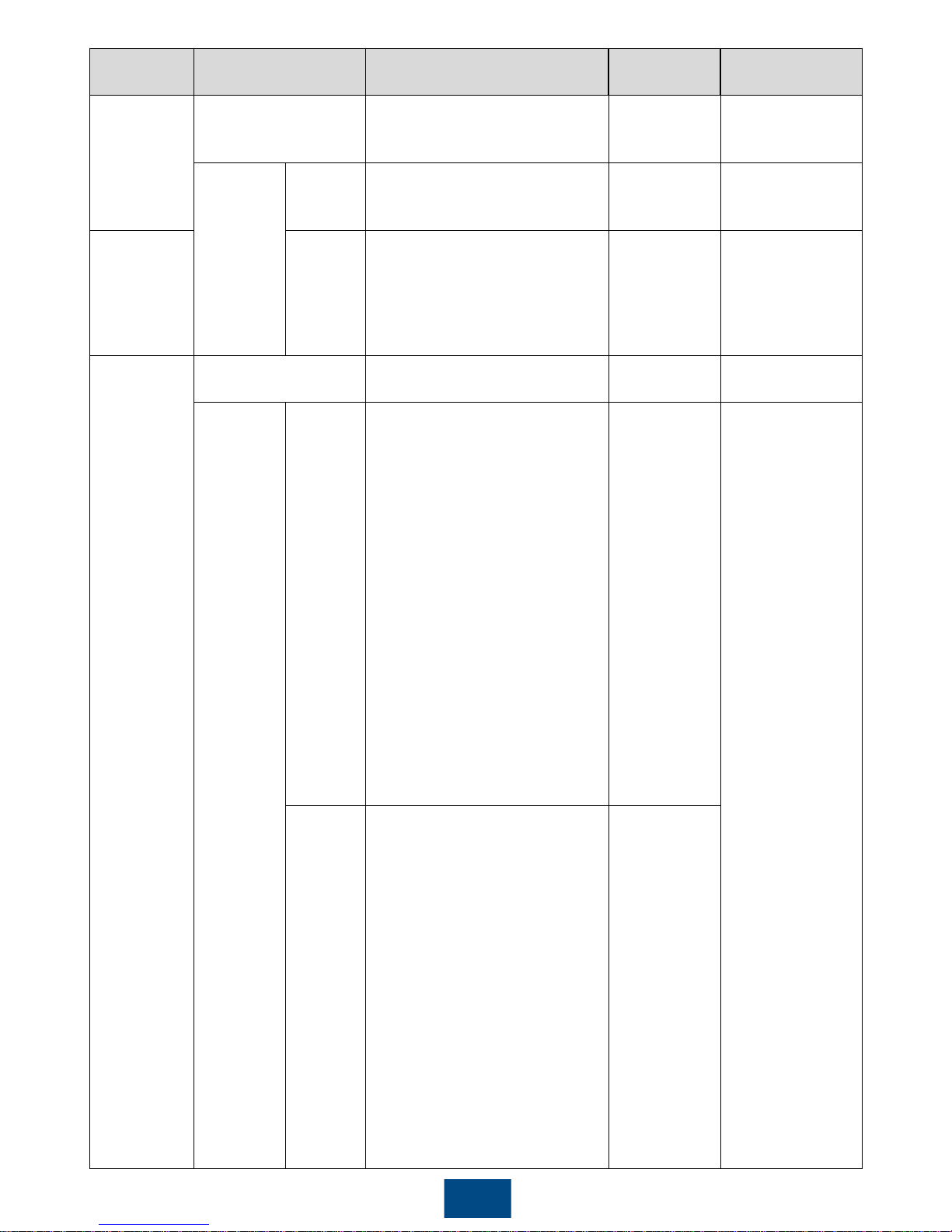
Optical Fiber
Page 7
6
Location Component
Recommended Model or
Specifications
Component
Source
Quantity
Smart array
controller
LAN switch (optional) UT-H605 or ES1000
Can be
purchased
from Huawei
1
Fitting bag
for optical
ring
switching
Lowspeed
optical
module
FTLF1323P1BTR-HW
Can be
purchased
from Huawei
2
Optical
jumper
PLCLC5S-ST3P302-HW, LC-
LC-S2-L2,
3ECA1031LCLC002-01-F, or
LP-LP-2S-P-SM-002
8
Box-type
transformer
MCB
Rated current: 32 A, number of
poles: 2
Prepared by
the customer
1
Threephase
power
switch
Knife
fuse
switch
(solution
1)
When the rated AC voltage
on the low-voltage side of
the box-type transformer is
less than or equal to 500 V,
the rated voltage should be
greater than or equal to 500
V. When the rated AC
voltage on the low-voltage
side of the box-type
transformer is greater than
500 V and less than or
equal to 800 V, the rated
voltage should be greater
than or equal to 800 V.
Rated current of the fuse:
32 A; rated current of the
knife fuse switch box ≥ 32 A;
number of poles: 3 (3 fuses
for each knife fuse switch
box)
Prepared by
the customer
Scenario with a
double-column
transformer: 1
Scenario with a
dual-split
transformer: 2
MCCB
(solution
2)
When the rated AC voltage
on the low-voltage side of
the box-type transformer is
less than or equal to 500 V,
the rated voltage should be
greater than or equal to 500
V. When the rated AC
voltage on the low-voltage
side of the box-type
transformer is greater than
500 V and less than or
equal to 800 V, the rated
voltage should be greater
than or equal to 800 V.
Let-through energy ≤ 1.26 x
106A2s
Rated current: 32 A;
number of poles: 3
Prepared by
the customer
Page 8
7
4G LTE
Page 9
8
Location Component
Recommended Model or
Specifications
Component
Source
Quantity
Smart array
controller
LAN switch (optional) UT-H605 or ES1000
Can be
purchased
from Huawei
1
Fitting
bags for
the POE
module
and
customerpremises
equipment
(CPE)
POE
module
N/A
Can be
purchased
from Huawei
1
Outside the
smart array
controller
and boxtype
transformer
CPE
N/A
Can be
purchased
from Huawei
1
Box-type
transformer
MCB
Rated current: 32 A, number of
poles: 2
Prepared by
the customer
1
Three-
phase
power
switch
Knife
fuse
switch
(solution
1)
When the rated AC voltage
on the low-voltage side of
the box-type transformer is
less than or equal to 500 V,
the rated voltage should be
greater than or equal to 500
V. When the rated AC
voltage on the low-voltage
side of the box-type
transformer is greater than
500 V and less than or
equal to 800 V, the rated
voltage should be greater
than or equal to 800 V.
Rated current of the fuse:
32 A; rated current of the
knife fuse switch box ≥ 32 A;
number of poles: 3 (3 fuses
for each knife fuse switch
box)
Prepared by
the customer
Scenario with
a double-
column
transformer: 1
Scenario with
a dual-split
transformer: 2
MCCB
(solution
2)
When the rated AC voltage
on the low-voltage side of
the box-type transformer is
less than or equal to 500 V,
the rated voltage should be
greater than or equal to 500
V. When the rated AC
voltage on the low-voltage
side of the box-type
transformer is greater than
500 V and less than or
equal to 800 V, the rated
voltage should be greater
than or equal to 800 V.
Let-through energy ≤ 1.26 x
106A2s
Rated current: 32 A; number
of poles: 3
Prepared by
the customer
Page 10
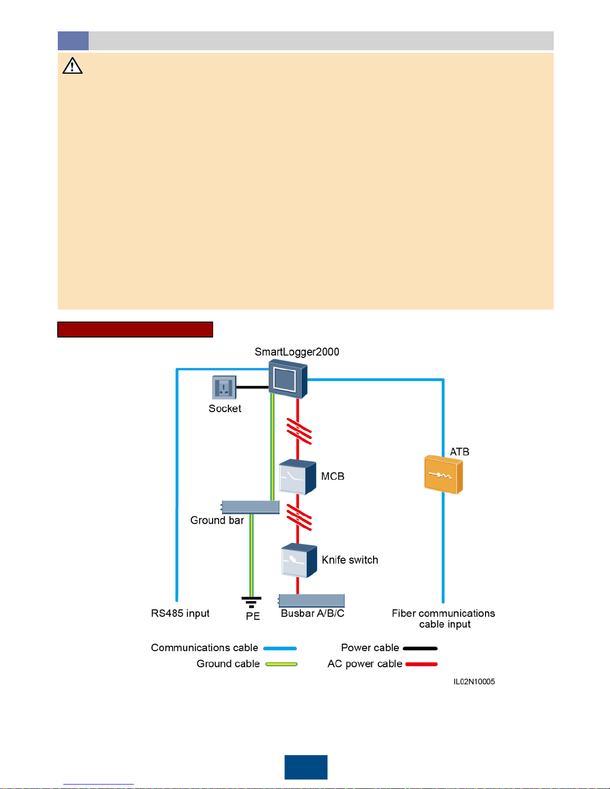
Non-Smart Array Controller Scenario
2.2
NOTICE
Optical Fiber
9
1. If the SmartLogger communicates with a SUN2000 over an AC power cable, an MCB and a knife
switch need to be installed to prevent device damage in the case of short circuits.
2. If the SmartLogger communicates with the SUN2000 over an AC power cable, prepare the cable
from the knife fuse switch to the MCB and the cable from the busbar to the knife fuse switch by
yourself. Recommended: a three-core outdoor armor cable with a cross-sectional area of 10 mm
2
for each core wire. When the rated AC voltage on the low-voltage side of the box-type transformer
is less than or equal to 500 V, the operating voltage between the AC power cable and the ground
should be greater than or equal to 600 V. When the rated AC voltage on the low-voltage side of
the box-type transformer is greater than 500 V and less than or equal to 800 V, the operating
voltage between the AC power cable and the ground should be greater than or equal to 1000 V.
3. The SmartLogger can connect to the SUN2000 through an RS485 communications cable or AC
power cable. If RS485 is used, there is no need to connect an AC power cable between the
SmartLogger and the MCB in the scenario without a smart array controller.
4. The power cable delivered with the SmartLogger is 1 meter long, the power adapter cable is 1.5
meters long, the network cable is 2.2 meters long, and the AC power cable is 1.5 meters long.
Reserve the installation positions for components based on the cable lengths.
Page 11
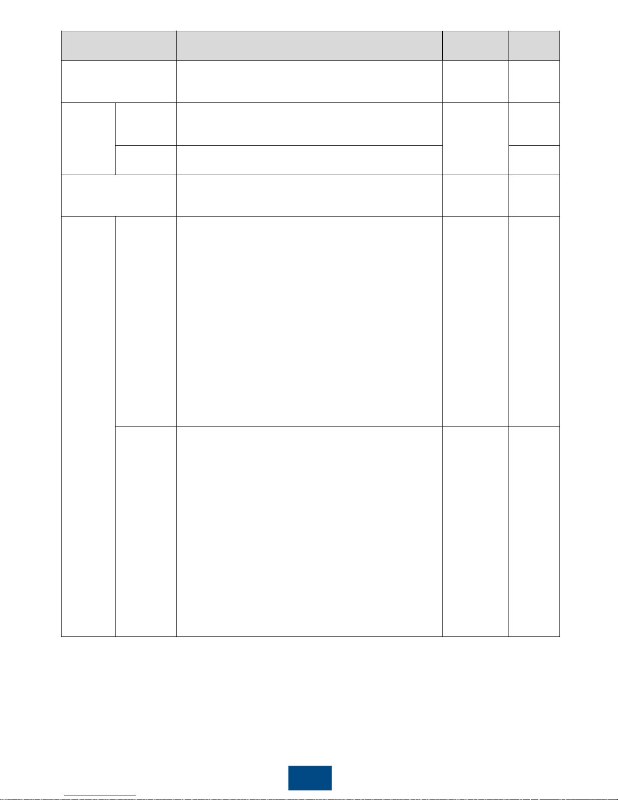
10
Component Recommended Model or Specifications
Component
Source
Quantity
SmartLogger SmartLogger2000
Can be
purchased
from Huawei
1
Fitting
bag for
fiber ring
switching
Low-speed
optical
module
FTLF1323P1BTR-HW
Can be
purchased
from Huawei
2
Optical
jumper
PLCLC5S-ST3P302-HW, LC-LC-S2-L2,
3ECA1031LCLC002-01-F, or LP-LP-2S-P-SM-002
8
ATB
CT-GZF2PJ-8, CT-GPH-A-8, or an ATB of a local
model
Prepared by
the customer
1
Knife
switch
Fuse
When the rated AC voltage on the low-voltage side
of the box-type transformer is less than or equal to
500 V, the rated voltage should be greater than or
equal to 500 V. When the rated AC voltage on the
low-voltage side of the box-type transformer is
greater than 500 V and less than or equal to 800 V,
the rated voltage should be greater than or equal to
800 V.
When the rated AC voltage on the low-voltage side
of the box-type transformer is less than or equal to
500 V, the rated current should be greater than or
equal to 6 A. When the rated AC voltage on the
low-voltage side of the box-type transformer is
greater than 500 V and less than or equal to 800 V,
the rated current should be greater than or equal to
32 A.
Prepared by
the customer
3
Knife
switch box
When the rated AC voltage on the low-voltage side
of the box-type transformer is less than or equal to
500 V, the rated voltage should be greater than or
equal to 500 V. When the rated AC voltage on the
low-voltage side of the box-type transformer is
greater than 500 V and less than or equal to 800 V,
the rated voltage should be greater than or equal to
800 V.
When the rated AC voltage on the low-voltage side
of the box-type transformer is less than or equal to
500 V, the rated current should be greater than or
equal to 6 A. When the rated AC voltage on the
low-voltage side of the box-type transformer is
greater than 500 V and less than or equal to 800 V,
the rated current should be greater than or equal to
32 A. The number of poles is 3.
Prepared by
the customer
1
Page 12
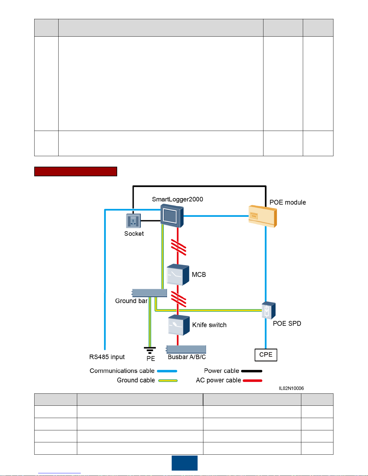
11
Component Recommended Model or Specifications Component Source Quantity
SmartLogger SmartLogger2000 Can be purchased from Huawei 1
POE module POE35-54A or POE85-56A Can be purchased from Huawei 1
POE SPD POE-2 Can be purchased from Huawei 1
CPE EG860V2-C71 Can be purchased from Huawei 1
4G LTE
Comp
onent
Recommended Model or Specifications
Component
Source
Quantity
MCB
When the rated AC voltage on the low-voltage side of the box-type
transformer is less than or equal to 500 V, the rated voltage should
be greater than or equal to 500 V. When the rated AC voltage on
the low-voltage side of the box-type transformer is greater than 500
V and less than or equal to 800 V, the rated voltage should be
greater than or equal to 800 V.
When the rated AC voltage on the low-voltage side of the box-type
transformer is less than or equal to 500 V, the rated current is
greater than or equal to 6 A and less than or equal to 32 A. When
the rated AC voltage on the low-voltage side of the box-type
transformer is greater than 500 V and less than or equal to 800 V,
the rated current is 32 A.
Prepared by
the customer
1
Socket Connects to the power adapter.
Prepared by
the customer
1
Page 13
12
Component Recommended Model or Specifications
Component
Source
Quantity
Knife
switch
Knife
switch
Fuse
When the rated AC voltage on the low-voltage side of
the box-type transformer is less than or equal to 500 V,
the rated voltage should be greater than or equal to
500 V. When the rated AC voltage on the low-voltage
side of the box-type transformer is greater than 500 V
and less than or equal to 800 V, the rated voltage
should be greater than or equal to 800 V.
When the rated AC voltage on the low-voltage side of
the box-type transformer is less than or equal to 500 V,
the rated current should be greater than or equal to 6 A.
When the rated AC voltage on the low-voltage side of
the box-type transformer is greater than 500 V and less
than or equal to 800 V, the rated current should be
greater than or equal to 32 A.
Prepared by
the customer
3
Knife
switch
box
When the rated AC voltage on the low-voltage side of
the box-type transformer is less than or equal to 500 V,
the rated voltage should be greater than or equal to
500 V. When the rated AC voltage on the low-voltage
side of the box-type transformer is greater than 500 V
and less than or equal to 800 V, the rated voltage
should be greater than or equal to 800 V.
When the rated AC voltage on the low-voltage side of
the box-type transformer is less than or equal to 500 V,
the rated current should be greater than or equal to 6 A.
When the rated AC voltage on the low-voltage side of
the box-type transformer is greater than 500 V and less
than or equal to 800 V, the rated current should be
greater than or equal to 32 A. The number of poles is 3.
Prepared by
the customer
1
MCB
When the rated AC voltage on the low-voltage side of
the box-type transformer is less than or equal to 500 V,
the rated voltage should be greater than or equal to
500 V. When the rated AC voltage on the low-voltage
side of the box-type transformer is greater than 500 V
and less than or equal to 800 V, the rated voltage
should be greater than or equal to 800 V.
When the rated AC voltage on the low-voltage side of
the box-type transformer is less than or equal to 500 V,
the rated current is greater than or equal to 6 A and
less than or equal to 32 A. When the rated AC voltage
on the low-voltage side of the box-type transformer is
greater than 500 V and less than or equal to 800 V, the
rated current is 32 A.
Prepared by
the customer
1
Socket Connects to the power adapter.
Prepared by
the customer
1
Page 14
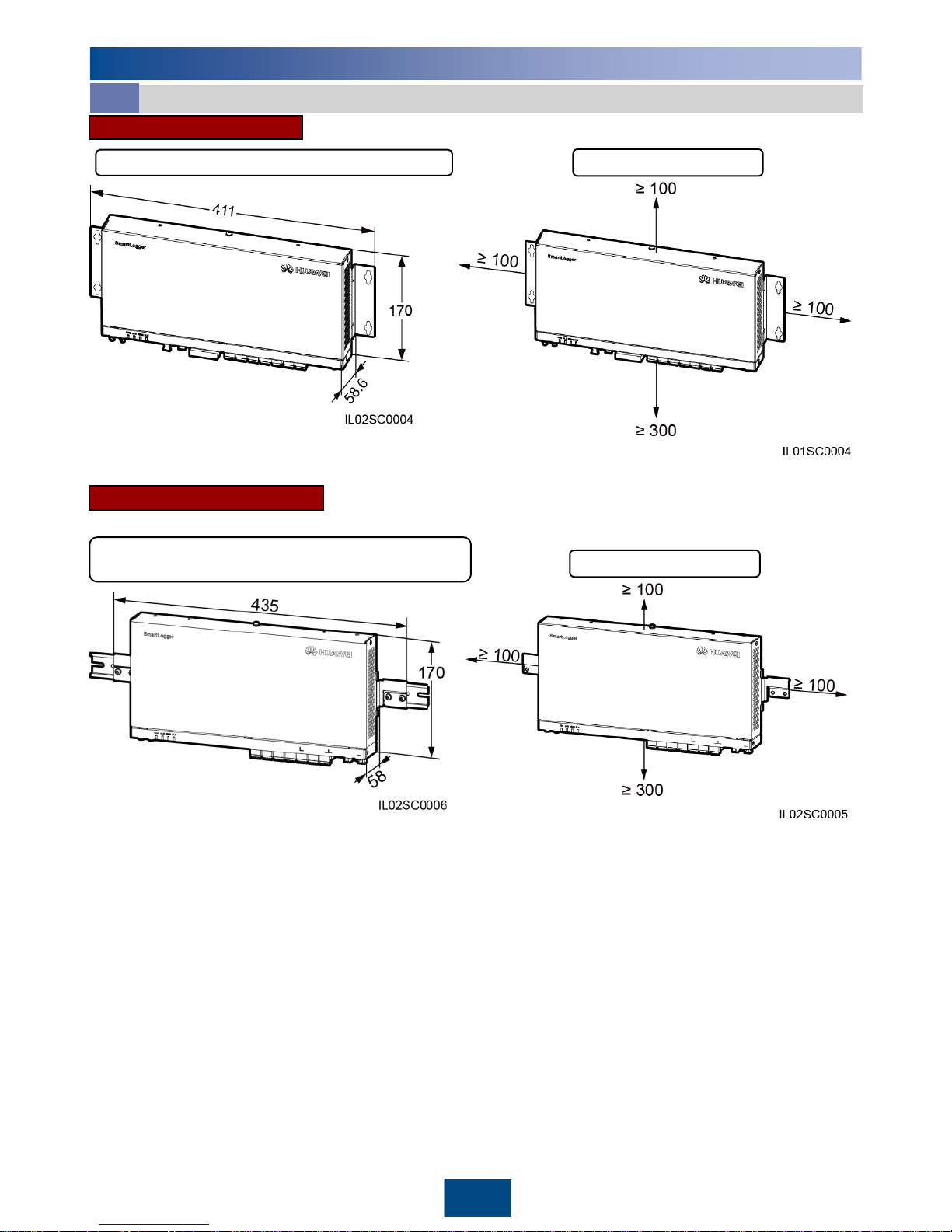
Installation clearances
Guide rail-mounting
Chassis dimensions
(including the guide rail mounting brackets)
13
Installation Space (Unit: mm)
3.1
3
Installing the SmartLogger
Chassis dimensions (including mounting ears) Installation clearances
Wall-mounting
Page 15
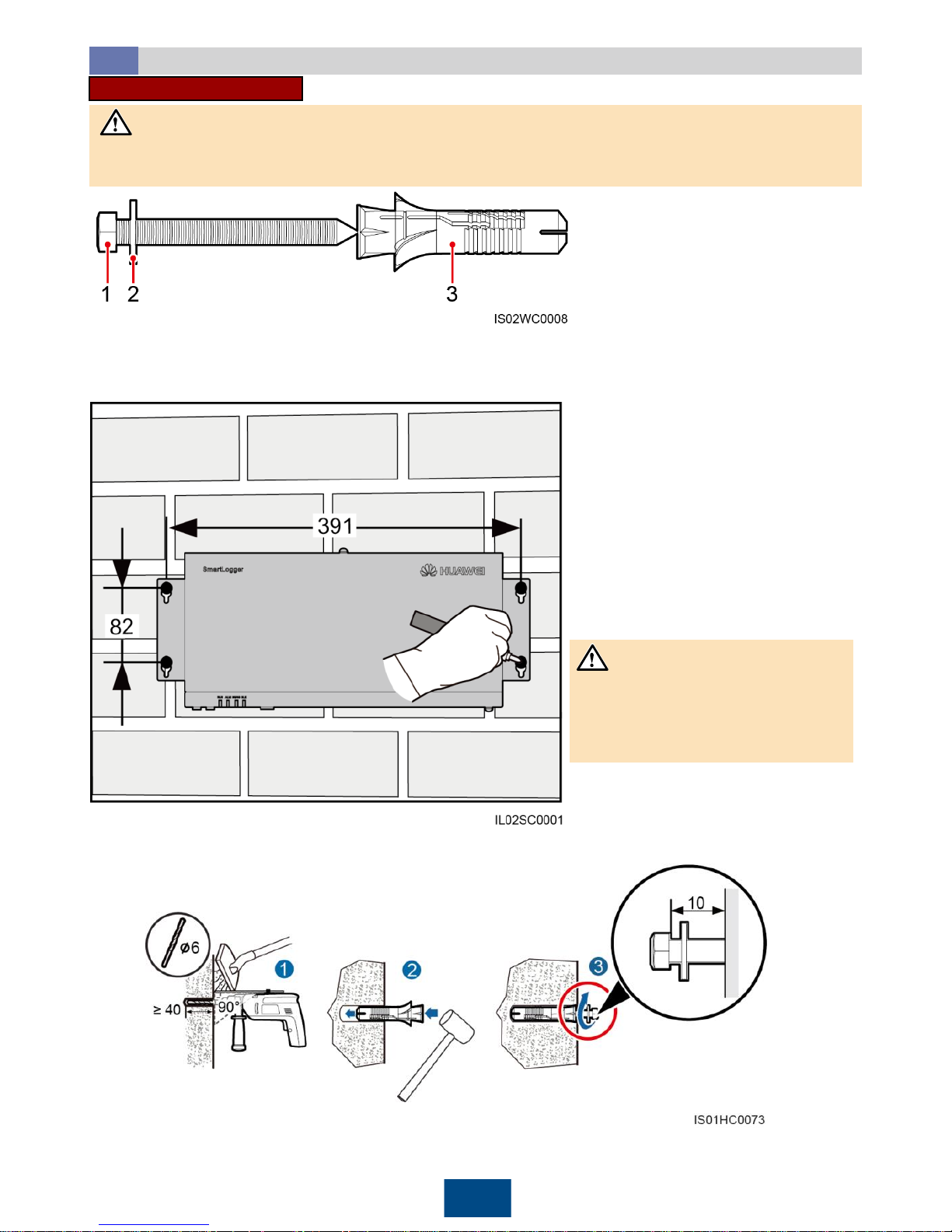
2. Drill holes by using a hammer drill and install expansion sleeves, washers, and tapping screws.
14
3. Put the tapping screws through the SmartLogger mounting ears and washers into the mounting
holes in the wall.
Unit: mm
1. Determine mounting holes based on the hole positions in the mounting ears, and mark
the mounting holes using a marker.
If you need to use a ladder to
install the device on a high
position, take measures to protect
yourself from falling down.
Unit: mm
NOTICE
Installation Mode
3.2
Wall-mounting
Install the SmartLogger on a wall that is flat and has the bearing capacity to securely hold the
SmartLogger.
NOTICE
Screw assembly for wall-mounting:
(1) ST3.5 tapping screw
(2) Washer
(3) Expansion sleeve
Page 16
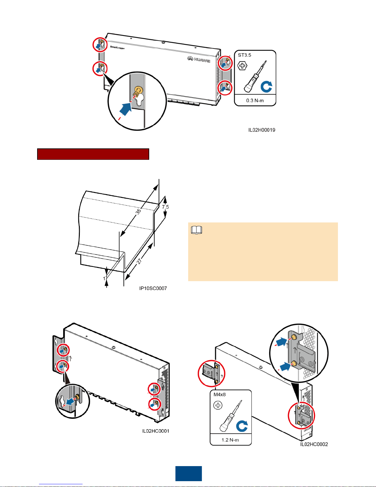
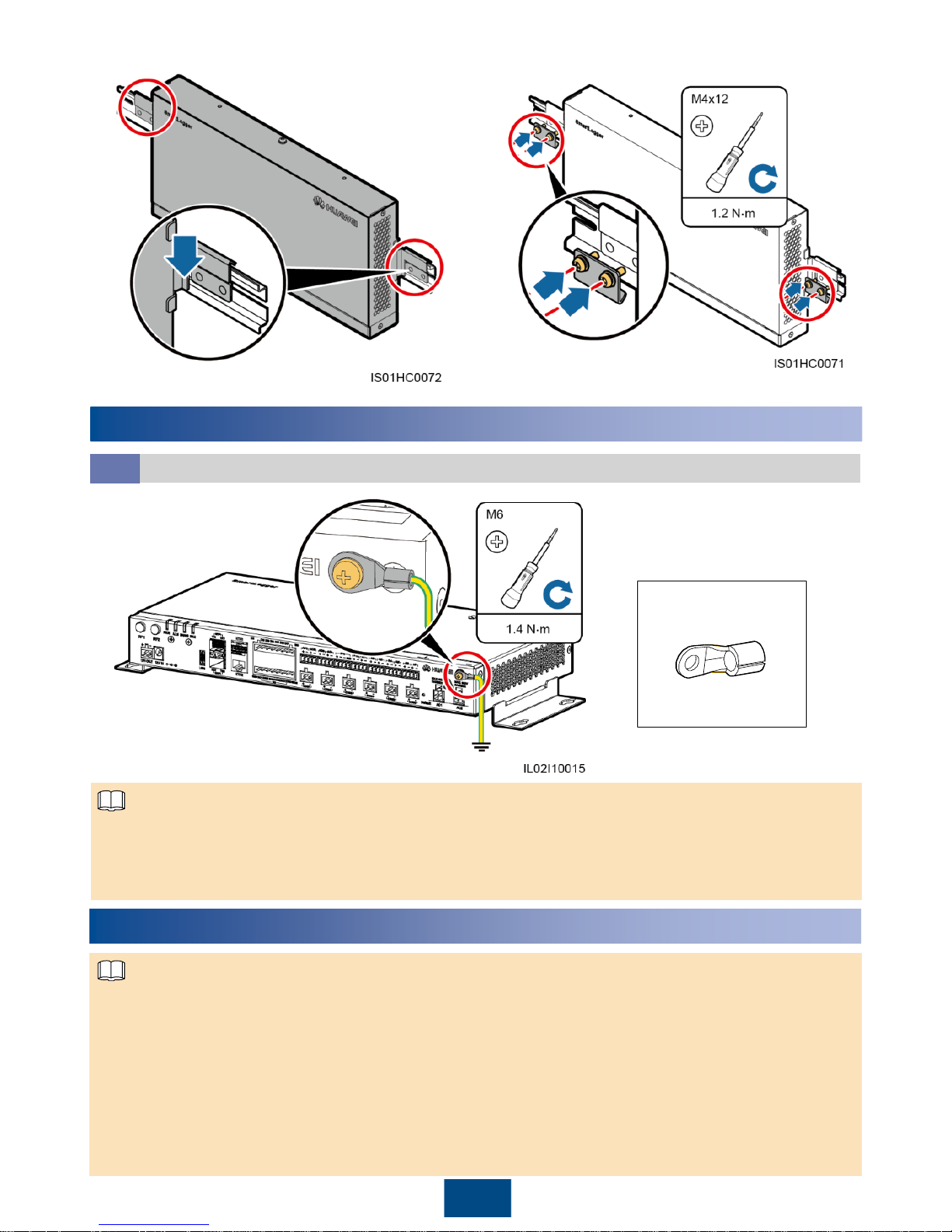
1. Remove the mounting ears from the
SmartLogger using a Phillips screwdriver.
2. Secure the guide rail clamps using the screws
that are removed from the mounting ears.
15
Guide rail-mounting
Huawei does not provide the SmartLogger guide rail. If the customer chooses this installation mode,
the customer must prepare a 35 mm standard guide rail.
Unit: mm
1. Secure the guide rail before mounting the
SmartLogger.
2. Verify that the length of the guide rail is
sufficient for securing the SmartLogger. The
recommended length is 450 mm or greater.
4. Tighten the tapping screws using a torque screwdriver.
NOTE
Page 17
16
4
Installing Ground Cable
3. Mount the SmartLogger onto the guide rail. 4. Install guide rail fasteners.
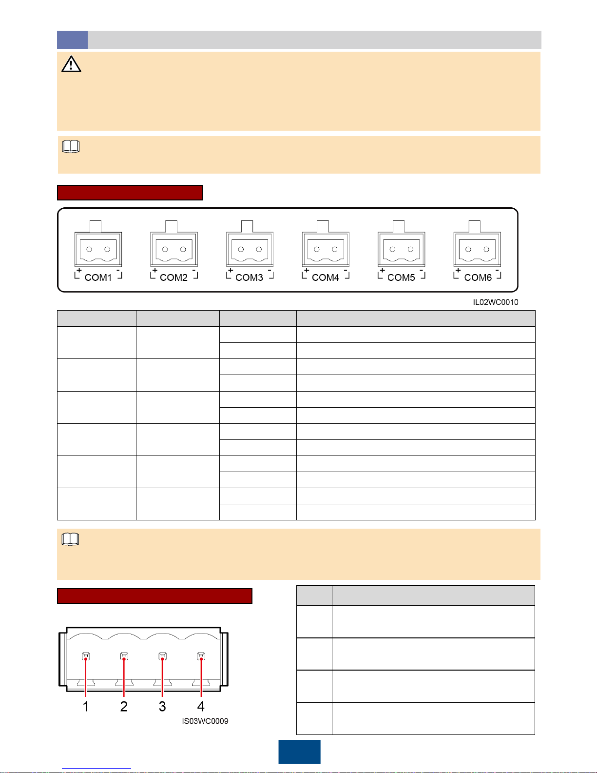
Installing the SmartLogger Ground Cable
4.1
1. It is recommended that 4–6 mm2or 12–10 AWG outdoor copper-core cables be used as ground
cables. Ground cables must be securely connected.
2. To enhance the corrosion resistance of the ground terminal, apply silica gel or paint on it after
connecting the PGND cable.
OT-M6
NOTE
5
Connecting Cables to COM Ports
The SmartLogger can connect to a SUN2000, an EMI, a power meter, a box-type transformer,
and a PID module through its COM ports.
If the SmartLogger2000-10/10-B/11-B connects to a device over the COM port, you are advised
to connect an external RS485 signal SPD. For details about how to install and connect the
RS485 signal SPD, see section 15.6 "How Should I Install the RS485 Signal SPD?" and section
15.7 "How Should I Connect the RS485 Signal SPD?"
If the SmartLogger2000-10-C/11-C connects to a device over the COM port, there is no need to
connect an external RS485 signal SPD. This document uses the SmartLogger2000-10-C as an
example to describe cable connections.
NOTE
Page 18
17
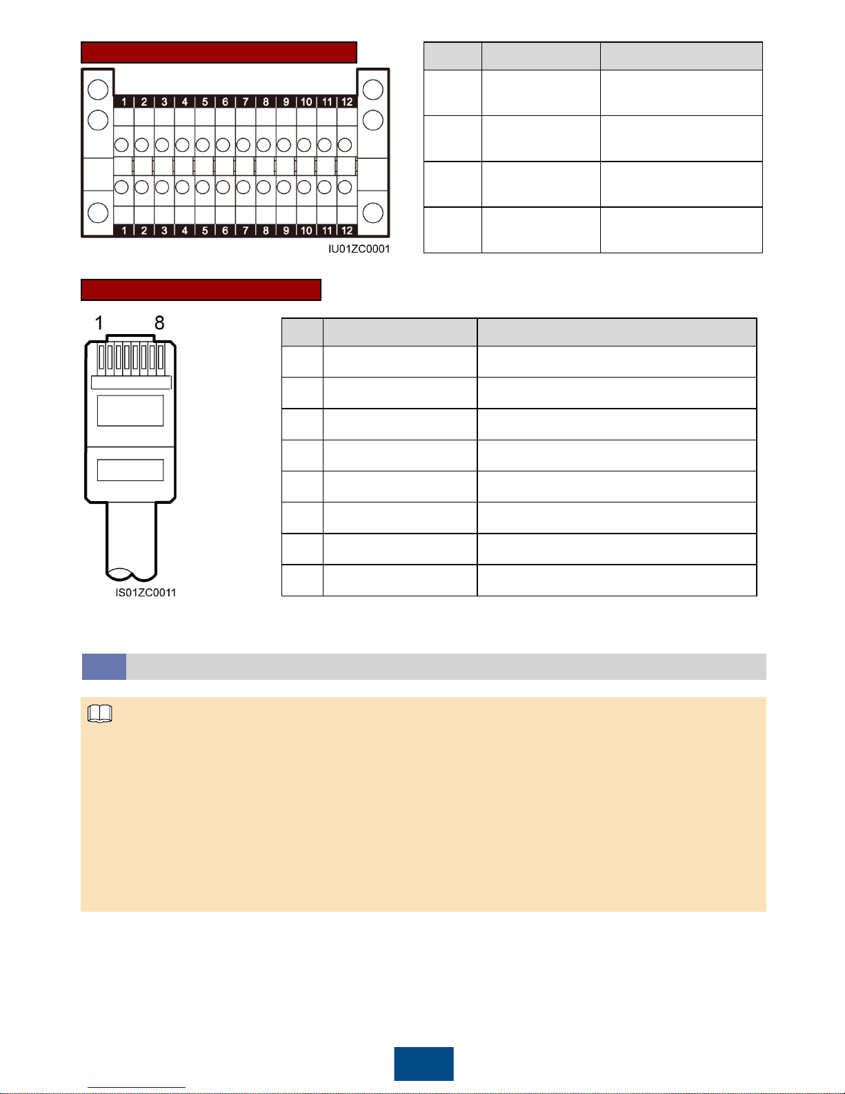
Port Definitions
5.1
COM Port (SmartLogger)
For the definitions of the communications ports on the devices such as the EMI, power meter, and
box-type transformer, see the documents delivered with the devices. When connecting cables,
ensure that RS485+ connects to the COM+ port on the SmartLogger and that RS485– connects to
the COM– port on the SmartLogger.
No. Port Symbol Function
1 COM1
+ RS485A, RS485 differential signal+
– RS485B, RS485 differential signal–
2 COM2
+ RS485A, RS485 differential signal+
– RS485B, RS485 differential signal–
3 COM3
+ RS485A, RS485 differential signal+
– RS485B, RS485 differential signal–
4 COM4
+ RS485A, RS485 differential signal+
– RS485B, RS485 differential signal–
5 COM5
+ RS485A, RS485 differential signal+
– RS485B, RS485 differential signal–
6 COM6
+ RS485A, RS485 differential signal+
– RS485B, RS485 differential signal–
NOTICE
For ease of operation, this document describes only the ports that need to be wired.
NOTE
Terminal block of types 1 and 2 are located in different models of SUN2000s.
The RJ45 network port is located in all models of SUN2000s.
NOTE
Terminal Block Type 1 (SUN2000)
No. Port Definition Function
1 RS485A IN
RS485A, RS485
differential signal+
2 RS485A OUT
RS485A, RS485
differential signal+
3 RS485B IN
RS485B, RS485
differential signal–
4 RS485B OUT
RS485B, RS485
differential signal–
Page 19
18
RJ45 Network Port (SUN2000)
No. Port Definition Function
5 RS485A IN
RS485A, RS485
differential signal+
6 RS485A OUT
RS485A, RS485
differential signal+
7 RS485B IN
RS485B, RS485
differential signal–
8 RS485B OUT
RS485B, RS485
differential signal–
No. Color Function
1 White orange RS485A, RS485 differential signal+
2 Orange RS485B, RS485 differential signal–
3 White green N/A
4 Blue RS485A, RS485 differential signal+
5 White blue RS485B, RS485 differential signal–
6 Green N/A
7 White brown N/A
8 Brown N/A
Terminal Block Type 2 (SUN2000)
1. Ensure that the RS485 communication distance is within 1000 meters.
2. The SmartLogger cable terminal block can connect to a cable with the maximum cross-sectional
area of 2.5 mm2.
3. A terminal block is recommended for connecting cables to the SUN2000. The following uses the
SUN2000-50KTL/50KTL-C1 terminal block as an example to describe cable connection.
4. When you connect a terminal block to the SUN2000, you are advised to use a computer cable
(DJYP2VP2-22 2x2x1) or a communications cable with the conductor cross-sectional area of 1
mm2and the cable outer diameter in the range of 14 mm to 18 mm.
5. When you connect the RJ45 network port to the SUN2000, you are advised to use the CAT 5E
outdoor shielded network cable.
Connecting an RS485 Communications Cable
5.2
NOTE
Page 20
19
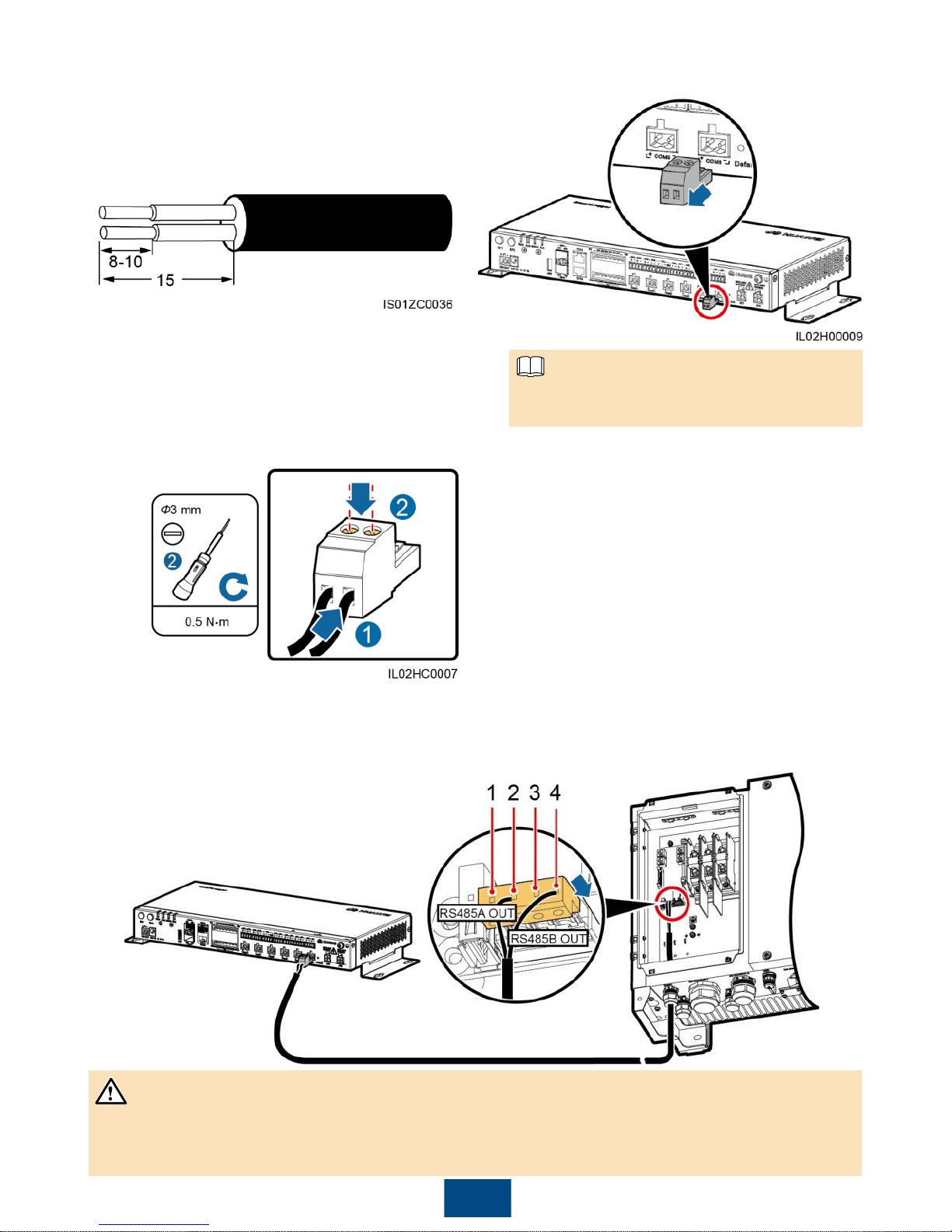
3. Connect one end of the cable to the SmartLogger terminal block.
2. Remove the terminal block from the
SmartLogger COM port.
Remove the terminal block using a flathead screwdriver.
NOTE
Unit: mm
1. Remove an appropriate length of the
steel armor and insulation layer from both
ends of the cable using a wire stripper.
4. Insert the terminal block into the SmartLogger COM port.
5. Strip an appropriate length from the other end of the cable and connect the end to the
SUN2000 terminal block.
Terminal definition:
(1) RS485A IN (2) RS485A OUT
(3) RS485B IN (4) RS485B OUT
• The RS485 IN and RS485 OUT ports on the SUN2000 can both connect to the SmartLogger. This
document uses the RS485 OUT port as an example to describe the connection between the
SUN2000 and the SmartLogger.
NOTICE
Page 21
20
Connecting Multiple Devices
5.3
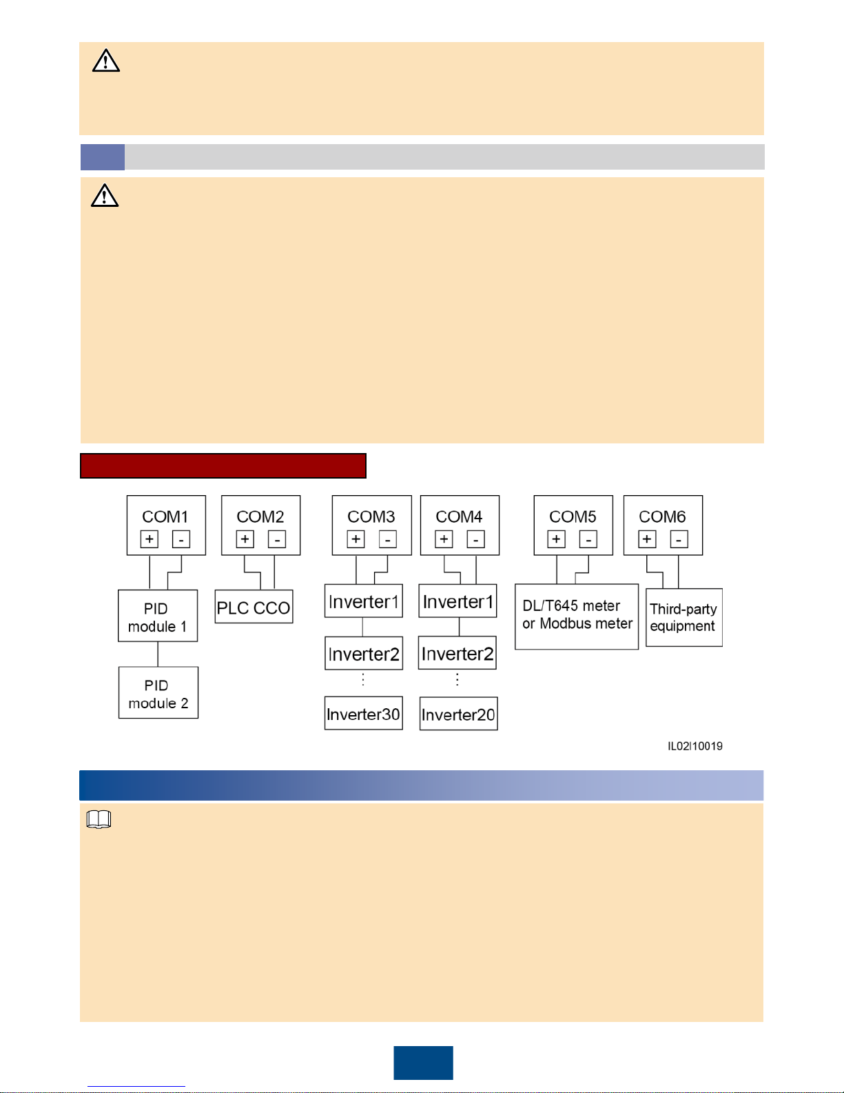
1. Each SmartLogger can connect to a maximum of 200 devices. You are advised to connect fewer
than 30 devices to each RS485 route.
2. Each SmartLogger2000-10/10-B/11-B connects to a maximum of 80 SUN2000s. Each
SmartLogger2000-10-C/11-C connects to a maximum of 150 SUN2000s.
3. Huawei equipment and third-party equipment need to be connected, you are advised to connect
them to different COM ports. If only Huawei equipment or third-party equipment needs to be
connected, connect it to any idle COM port.
4. Verify that devices using the same protocol are connected to the same COM port. Devices using
different protocols (for example, the box-type transformer which uses the IEC103 protocol and the
power meter which uses the DL/T645 protocol) need to be connected to separate COM ports.
5. If the model of the PID module connecting to the SmartLogger is SmartPID2000, one
SmartLogger can connect to two PID modules.
Recommended Connection Mode
NOTICE
1. If the SUN2000 is equipped with a PLC device, the SmartLogger can communicate with the
SUN2000 through an AC power cable.
2. If the SmartLogger2000-10-C communicates with the SUN2000 over PLC, each
SmartLogger2000-10-C can connect to a maximum of 80 SUN2000s over the AC port, and can
connect to a maximum of 150 SUN2000s over the AC and COM ports when an external PLC
CCO is connected.
3. If the SmartLogger uses an AC power cable for communication, an MCB or a knife switch needs
to be installed to prevent device damage in the case of short circuits.
4. If the SmartLogger is connected to the SUN2000 through an AC power cable, no RS485
communications cable needs to be connected.
Connecting Cables to AC Ports
6
NOTE
• Ensure that the SmartLogger COM+ (RS485A) port connects to the 2 (RS485A OUT) terminal on
the SUN2000 terminal block, and that the SmartLogger COM– (RS485B) port connects to the 4
(RS485B OUT) terminal on the SUN2000 terminal block.
NOTICE
Page 22
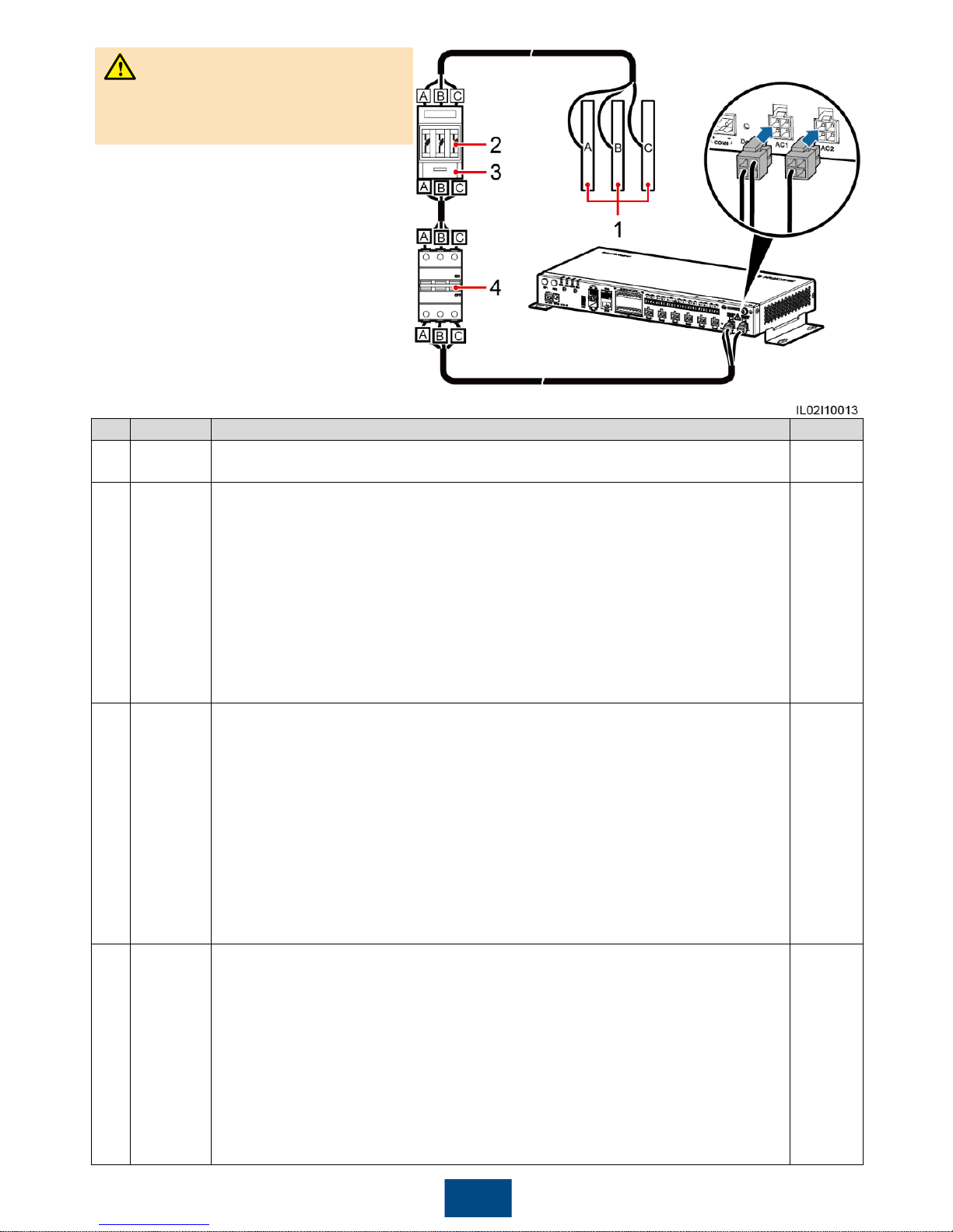
2. Connect the AC1 and AC2 terminals
at the other end of the cable to the
AC1 and AC2 ports on the
SmartLogger respectively.
1. Connect one end of the delivered AC
power cable to an MCB.
21
Before connecting the AC power cable,
ensure that the upstream switch of the
AC power cable is turned off.
WARNING
No.
Material
Model/Specifications
Quantity
1
Bus
bar
A/B/C
N/A
1
2
Fuse
When the rated AC voltage on the low-voltage side of the box-type
transformer is less than or equal to 500 V, the rated voltage should be
greater than or equal to 500 V. When the rated AC voltage on the lowvoltage side of the box-type transformer is greater than 500 V and less
than or equal to 800 V, the rated voltage should be greater than or equal
to 800 V.
When the rated AC voltage on the low-voltage side of the box-type
transformer is less than or equal to 500 V, the rated current should be
greater than or equal to 6 A. When the rated AC voltage on the low-
voltage
side of the box-type transformer is greater than 500 V and less than or
equal to 800 V, the rated current should be greater than or equal to 32 A.
3
3
Knife
switch
When the rated AC voltage on the low-voltage side of the box-type
transformer is less than or equal to 500 V, the rated voltage should be
greater than or equal to 500 V. When the rated AC voltage on the lowvoltage side of the box-type transformer is greater than 500 V and less
than or equal to 800 V, the rated voltage should be greater than or equal
to 800 V.
When the rated AC voltage on the low-voltage side of the box-type
transformer is less than or equal to 500 V, the rated current should be
greater than or equal to 6 A. When the rated AC voltage on the low-
voltage
side of the box-type transformer is greater than 500 V and less than or
equal to 800 V, the rated current should be greater than or equal to 32 A.
The number of poles is 3.
1
4
MCB
When the rated AC voltage on the low-voltage side of the box-type
transformer is less than or equal to 500 V, the rated voltage should be
greater than or equal to 500 V. When the rated AC voltage on the low-
voltage side of the box-type transformer is greater than 500 V and less
than or equal to 800 V, the rated voltage should be greater than or equal
to 800 V.
When the rated AC voltage on the low-voltage side of the box-type
transformer is less than or equal to 500 V, the rated current is greater than
or equal to 6 A and less than or equal to 32 A. When the rated AC voltage
on the low-voltage side of the box-type transformer is greater than 500 V
and less than or equal to 800 V, the rated current is 32 A.
1
Page 23
22
7
Connecting a Cable to the DI Port
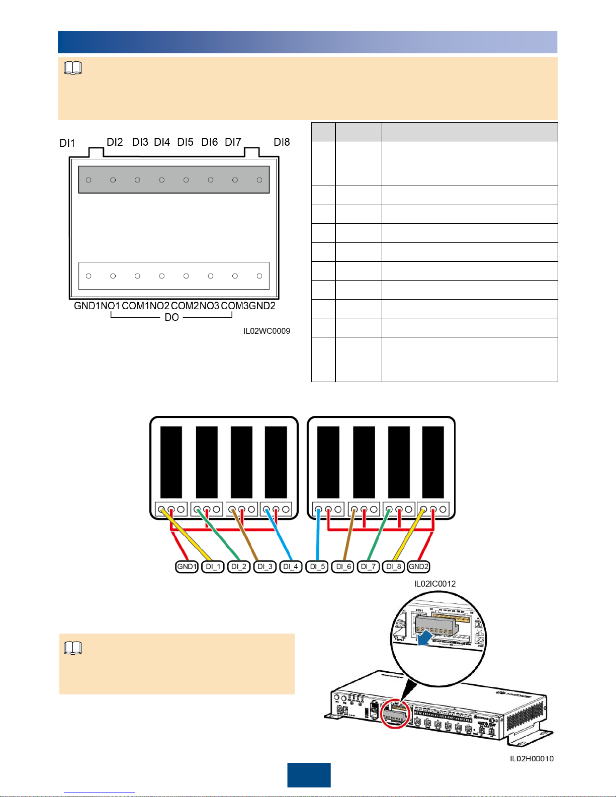
1. In Germany and some other European areas, a ripple control receiver is used to convert a power
grid scheduling signal to a dry contact signal, in which a dry contact is needed.
2. Two-core or multiple-core cables with a cross sectional area of 1.5 mm2are recommended.
No. Port Function
1 GND1
Dry contact input common terminal
1, used for active power derating
for DI1–DI4
2 DI1 DI_1
3 DI2 DI_2
4 DI3 DI_3
5 DI4 DI_4
6 DI5 DI_5
7 DI6 DI_6
8 DI7 DI_7
9 DI8 DI_8
10 GND2
Dry contact input common terminal
2, used for reactive power
compensation for DI5–DI8
NOTE
1. Prepare a cable with an appropriate length, strip a part of the insulation layer, and connect the
stripped cable core to the ripple control receiver.
3. Remove the terminal block from the SmartLogger DI port.
Remove the terminal block using a flat-head
screwdriver.
NOTE
2. Strip 8 mm of the insulation layer at the other end.
Page 24
23
8
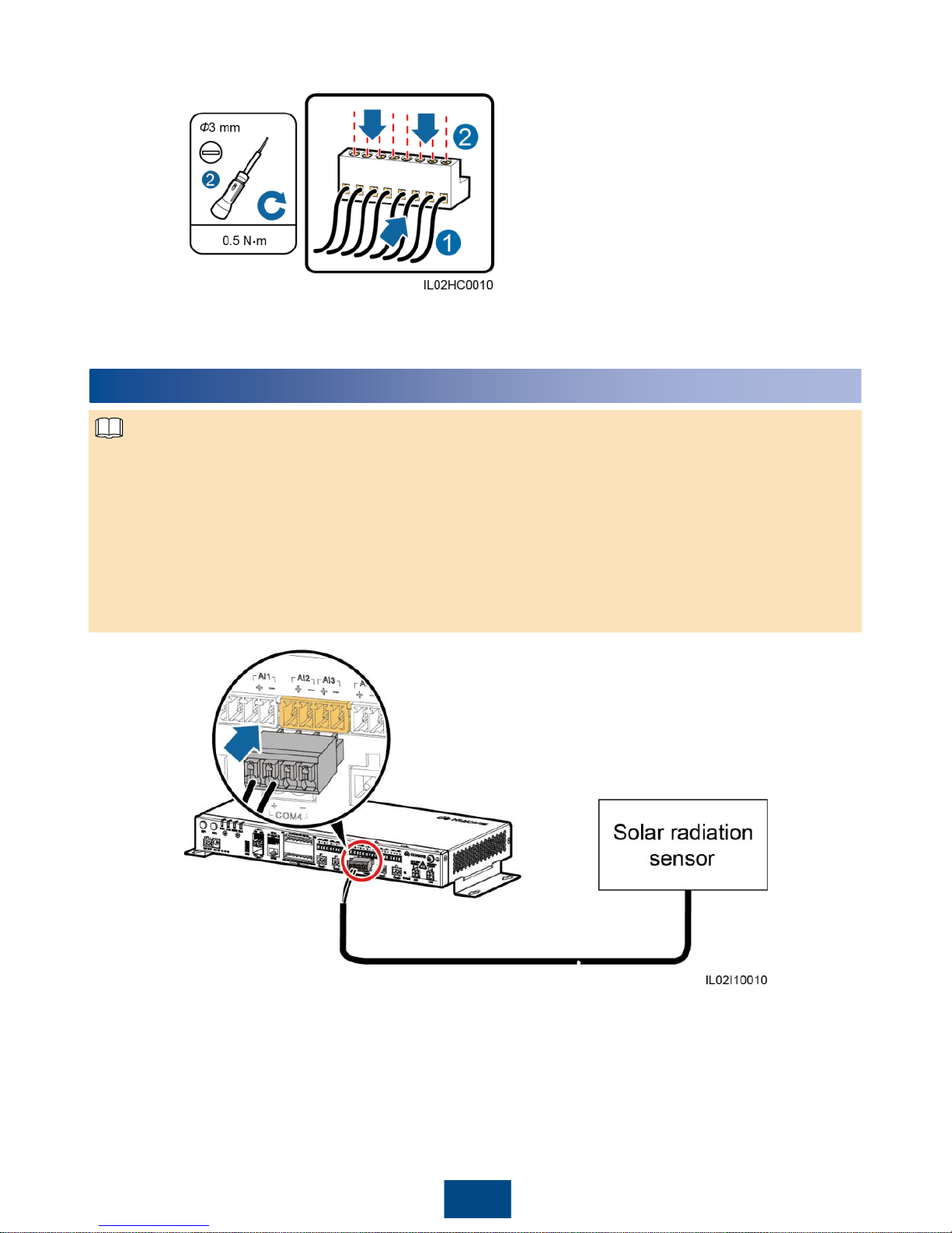
1. The EMI used in Europe and Southeast Asia is composed of sensors that need to connect to
the SmartLogger separately.
2. The SmartLogger can connect to a current-type or voltage-type sensor through an AI port.
3. One sensor connects to one AI port. This document describes only the connection between the
solar radiation sensor and the SmartLogger. Connections between other sensors and the
SmartLogger are the same.
4. For details about the cables and cable connection operations, see the documents delivered with
the sensors. The AI port on the SmartLogger is marked + and –. Connect cables correctly
according to the silk screens.
8
Connecting Cables to the AI Port
NOTE
4. Connect the stripped cable core to the terminal block of the DI port on the SmartLogger.
5. Insert the terminal block into the SmartLogger DI port.
Page 25
24
9
Connecting Cables to the PT Port
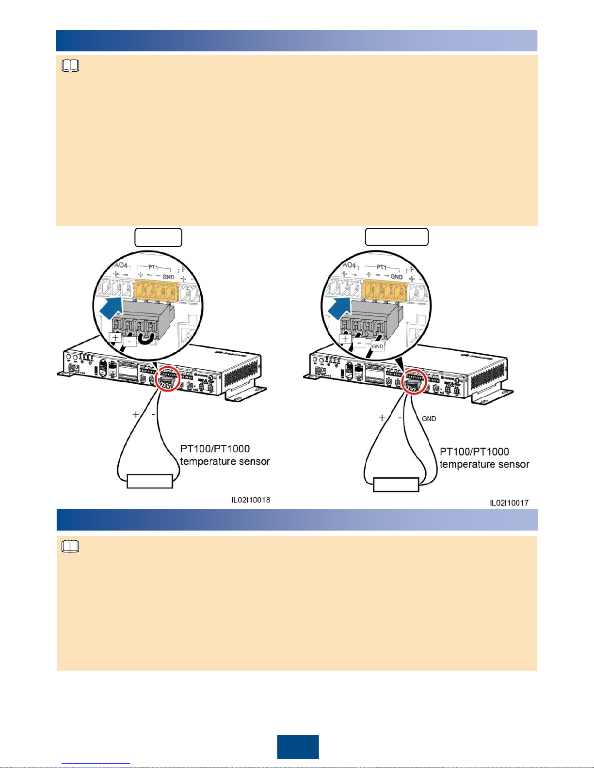
1. The EMI used in Europe and Southeast Asia is composed of sensors that need to connect to the
SmartLogger separately.
2. The SmartLogger2000-10-C/11-C can connect to a PT100/PT1000 temperature sensor through a
PT port.
3. If the AI port has connected to a temperature sensor, the PT port can be reserved.
4. The PT1 port can connect to a three-wire or two-wire PT100/PT1000 temperature sensor,
whereas the PT2 port can connect to only a two-wire PT100/PT1000 temperature sensor.
5. If the PT1 port connects to a two-wire PT100/PT1000 temperature sensor, you need to shortcircuit the GND port to one – port using the delivered short-circuit cable.
6. For details about the cables and cable connection operations, see the documents delivered with
the PT100/PT1000 temperature sensor. The PT port on the SmartLogger is marked + and –.
Connect cables correctly according to the silk screens.
Three-wireTwo-wire
NOTE
10
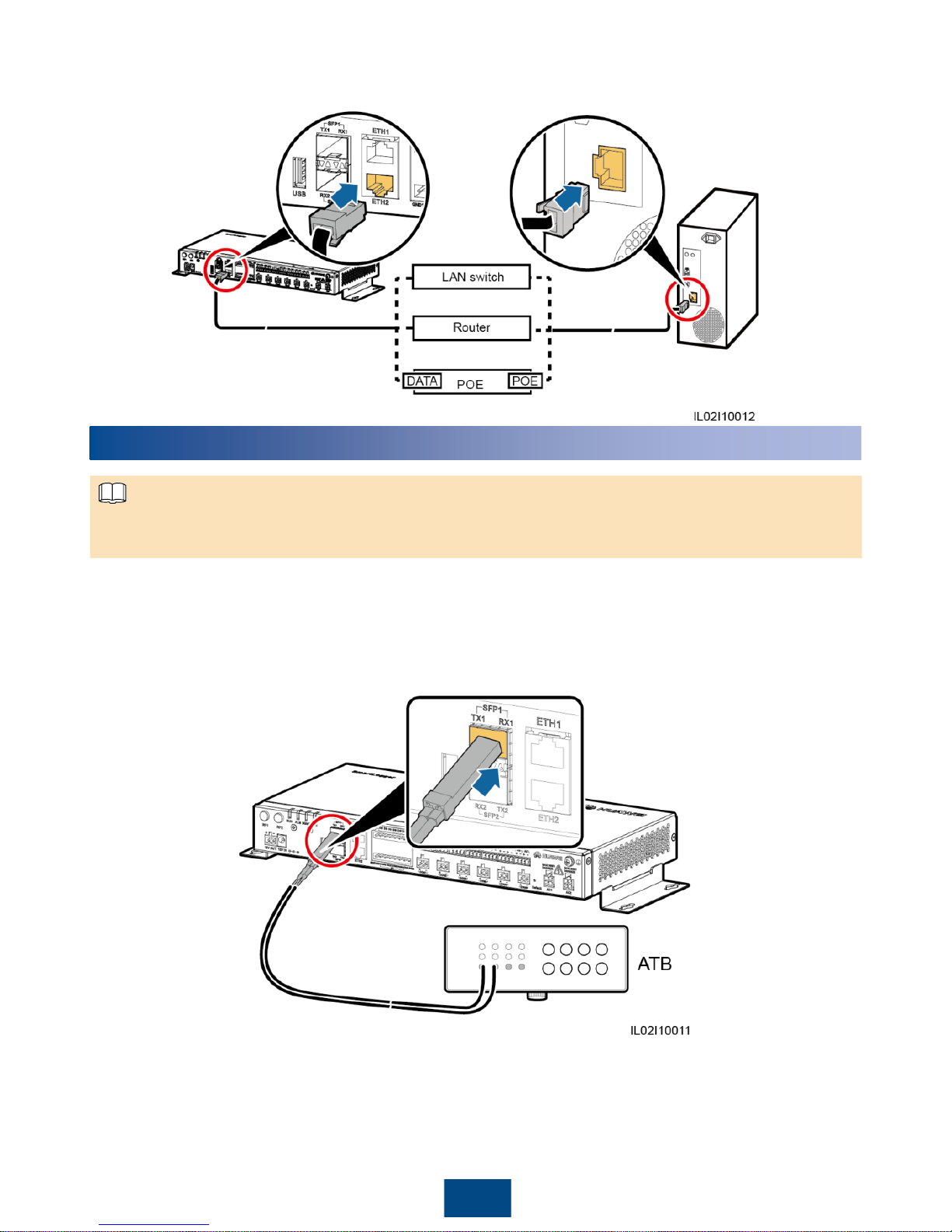
Connecting Network Cables to the Ethernet Electrical Port
1. The SmartLogger provides two Ethernet electrical ports, through which the SmartLogger can
connect to a third-party device.
2. The SmartLogger can be connected to an Ethernet LAN switch, router, or POE device, and then
connected to a PC. It can also be directly connected to a PC. Select the connection device
based on the actual networking scenario.
3. If the cable between the SmartLogger and the PC over the devices such as a POE is routed
outdoors, connect a POE SPD to the POE to enhance the surge protection function. Connect
the POE port on the POE to the PROTECT port on the POE SPD.
4. Verify that the Ethernet communications cable is no longer than 100 m.
NOTE
Page 26
25
1. Connect one end of the delivered network cable to the Ethernet electrical port of a device.
2. Connect the other end of the network cable to the ETH1 or ETH2 port of the SmartLogger.
11
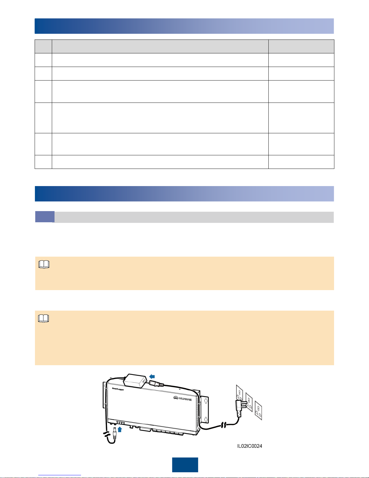
Connecting Optical Fibers to the Ethernet Optical Port
The SmartLogger can be connected to devices such as an ATB through optical fibers. You can select
the devices to be connected based on the actual networking scenario.
1. Insert the optical module into the SFP1 or SFP2 port of the SmartLogger.
2. Connect the two cables delivered with the optical module to the ports on the optical module.
3. Connect the other ends of the cables to the ports of the device on the other side (such as an ATB).
NOTE
Page 27
12
Verifying the Installation
No. Check That Check Result
1 The SmartLogger is properly installed.
□
Passed □Failed
2 All cables are properly connected, without open circuits or short circuits.
□
Passed □Failed
3
Unused ports (such as RF1, RF2, Ethernet optical port, and Ethernet
electrical port) are protected by dustproof plugs.
□
Passed □Failed
4
Routing for the power cable and signal cable meets the requirements for
routing strong-current and weak-current cables and complies with the
cable routing plan.
□
Passed □Failed
5
Cables are bound neatly, and cable ties are secured evenly and properly
in the same direction.
□
Passed □Failed
6 There is no unnecessary adhesive tape or cable tie on cables.
□
Passed □Failed
13
Powering On the System
Power-on Procedure
13.1
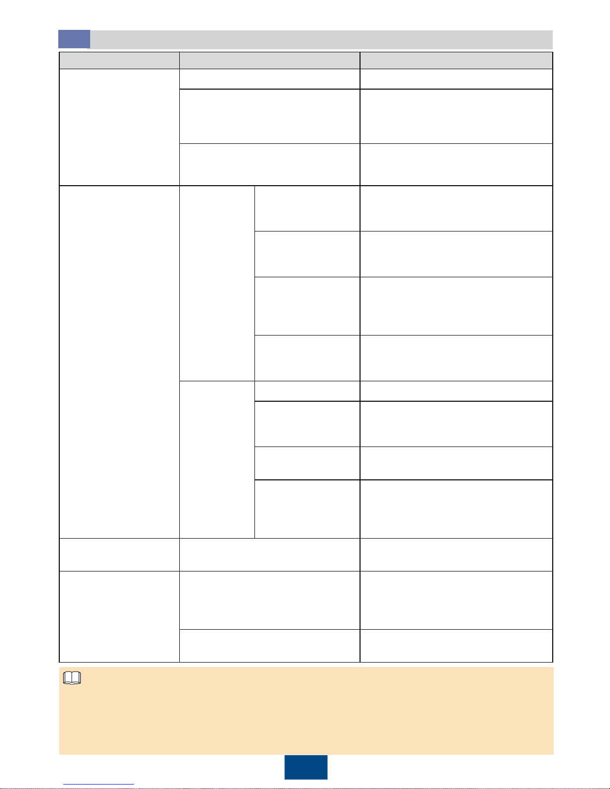
1. Insert the output terminal of the power adapter into the 12V IN port of the SmartLogger.
2. Insert the power cable into the power adapter.
3. Insert the power cable plug into an AC socket.
The rated input of the power adapter is 100–240 V AC, 50 Hz or 60 Hz.
Select an AC socket that matches the power adapter.
4. Switch on the circuit breaker of the AC socket.
5. Switch on the upstream circuit breaker of the AC power cable.
NOTE
Step 5 needs to be performed only in the PLC networking scenario.
In a scenario without a smart array controller, place the power adapter on the top of the
SmartLogger and secure the power adapter using a cable tie.
The adapters and sockets vary in different regions. The following figure is for reference only. The
actual objects prevail.
NOTE
26
Page 28
27
Indicator (Silk Screen)
Status Meaning
Running indicator
(RUN)
Green off
The SmartLogger is not powered on.
Blinking green quickly (on for
0.125s and then off for 0.125s)
The SmartLogger and NMS (Huawei
NMS or a third
-party NMS) are not
connected or the communication
between them is interrupted.
Blinking green slowly (on for 1s and
then off for 1s)
The SmartLogger properly
communicates with the NMS (Huawei
NMS or a third
-party NMS).
Alarm/maintenance
indicator (ALM)
Alarm status
Red off
The SmartLogger and the devices
connected to it do not generate any
alarm.
Blinking red at long
intervals (on for 1s
and then off for 4s)
The SmartLogger or the devices
connected to it generate warnings.
Blinking red at short
intervals (on for
0.5s and then off for
0.5s)
The SmartLogger or the devices
connected to it generate minor alarms.
Steady red
The SmartLogger or the devices
connected to it generate major alarms.
Maintenance
status
Green off
No near
-end maintenance.
Blinking green
slowly (on for 1s
and then off for 1s)
Near
-end maintenance is in progress.
Steady green
The near
-end maintenance is
successful.
Blinking green
quickly (on for
0.125s and then off
for 0.125s)
The near
-end maintenance failed.
3G/4G indicator
(3G/4G)
N/A
Reserved.
Bluetooth indicator
(BLE)
Green off
You have not logged in to the APP or
login failed. The
SmartLogger is not
connected to the APP or the
communication has been interrupted.
Blinking green slowly (on for 1s and
then off for 1s)
You have successfully logged in to the
app.
LED Indicators (from Left to Right)
13.2
• If an alarm and local maintenance happen concurrently, the alarm/maintenance indicator shows
the near-end maintenance state first. After the USB flash drive is removed, the indicator shows
the alarm state.
• Log in to the built-in WebUI or app of the SmartLogger to view its running status and device
connections. For details, see the SmartLogger2000 User Manual or SUN2000 APP User Manual.
NOTE
Page 29
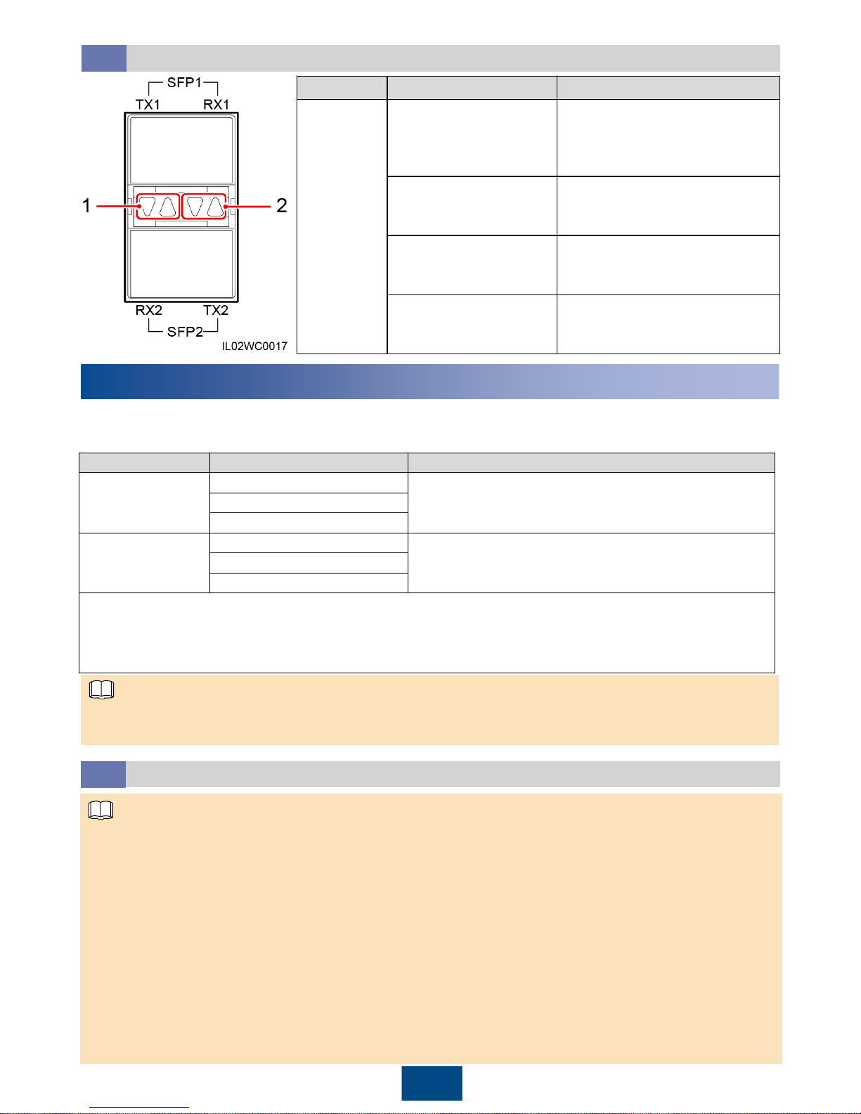
Indicator Status Meaning
(1) Upper
optical port
(2) Lower
optical port
Green and yellow off
No
optical module is inserted
into the Ethernet
optical port.
Green steady on and
yellow blinking quickly
(0.1s on and 0.1s off)
The fiber link is being set up.
Green steady on and
yellow blinking
intermittently
The data is being transmitted.
Green steady on and
yellow blinking slowly
(0.1s on and 1.9s off)
The fiber link is normal.
Optical Port Indicators
13.3
14
System Commissioning
NOTE
1. The SUN2000 app is a convenient maintenance platform that communicates with the monitoring
system for you to query alarms, configure parameters, and perform routine maintenance. The app
name is displayed as SUN2000.
2. Mobile phone operating system: Android 4.0 or later, or iOS 7.0 or later.
3. To download the SUN2000 app software package available for Android, access Huawei app store
(http://appstore.huawei.com) or Google Play (https://play.google.com), and search for SUN2000.
4. To download the SUN2000 app software package available for iOS, access App Store and
searches for SUN2000.
5. The Android-oriented app connects to the monitoring system over Bluetooth or USB data cable.
The iOS-oriented app connects to the monitoring system over Bluetooth. The app connects to the
SmartLogger only over Bluetooth.
6. This document uses the WebUIs of Android-oriented SUN2000 app V200R001C00SPC020 as an
example.
Connecting the SUN2000 App
14.1
28
The SmartLogger can commission devices by connecting to the SUN2000 app, embedded WebUI,
and NMS.
Login Mode
User Name
Initial Password
SUN2000 app
Common user
00000a
Advanced user
Special user
Web UI
a
Common user
Changeme
Advanced user
Special user
Note a: If the SmartLogger connects to the WebUI, enter https://XX.XX.XX.XX (XX.XX.XX.XX is the
SmartLogger IP address and is 192.168.0.10 by default) in the address bar of the browser. The
SmartLogger IP address can be queried through the SUN2000 app. For details, see section 14.1
"Connecting the SUN2000 App."
1. Recommended: Change the initial password immediately after the first login to ensure account security.
2. This document uses the SUN2000 app as an example to describe major commissioning operations.
NOTE
Page 30
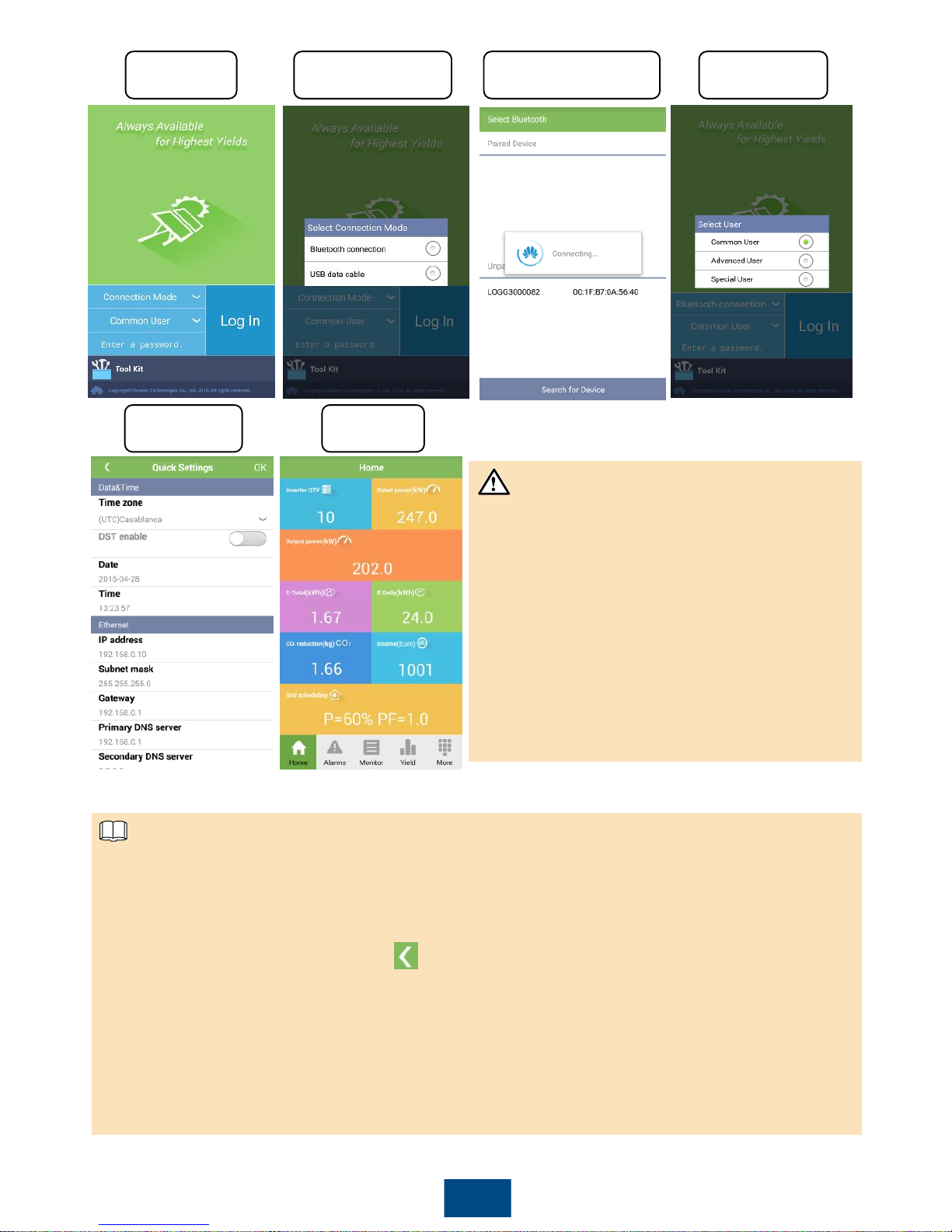
29
Login screen
Switching
between users
Select Bluetooth
connection
Connecting Bluetooth
Main menuQuick settings
1. The SmartLogger Bluetooth is named as
LOG+the last eight figures of the SN of the
SmartLogger.
2. The login password is the same as that for
the SmartLogger connected to the app and is
used only when the SmartLogger connects to
the app.
3. The preset password for Common User,
Advanced User, and Special User is
00000a. Use the preset password upon initial
login. To ensure account security, change the
password immediately after login.
NOTICE
1. If the SmartLogger is powered on for the first time or the factory defaults are restored and
parameter configuration is not performed on the embedded WebUI, the Quick Settings screen
is displayed when the SmartLogger connects to the app. You can set parameters based on site
requirements. After parameters are set, the main menu is displayed when the SmartLogger
connects to the app again.
2. On the Quick Settings screen, tap to return to the login screen. Then tap OK to confirm the
settings and enter the main menu.
3. In the Income pane, when Currency factor is 0 (default value), Income is --. You can set
Currency factor on the app.
4. In the Grid scheduling pane, if there is no active power scheduling, P = NA is displayed. If there
is no reactive power scheduling, PF = NA is displayed. For operations related to grid scheduling,
see the SmartLogger2000 User Manual.
5. You can modify the parameters based on site requirements. For details about parameter
configuration, see the SUN2000 APP User Manual.
NOTE
Page 31
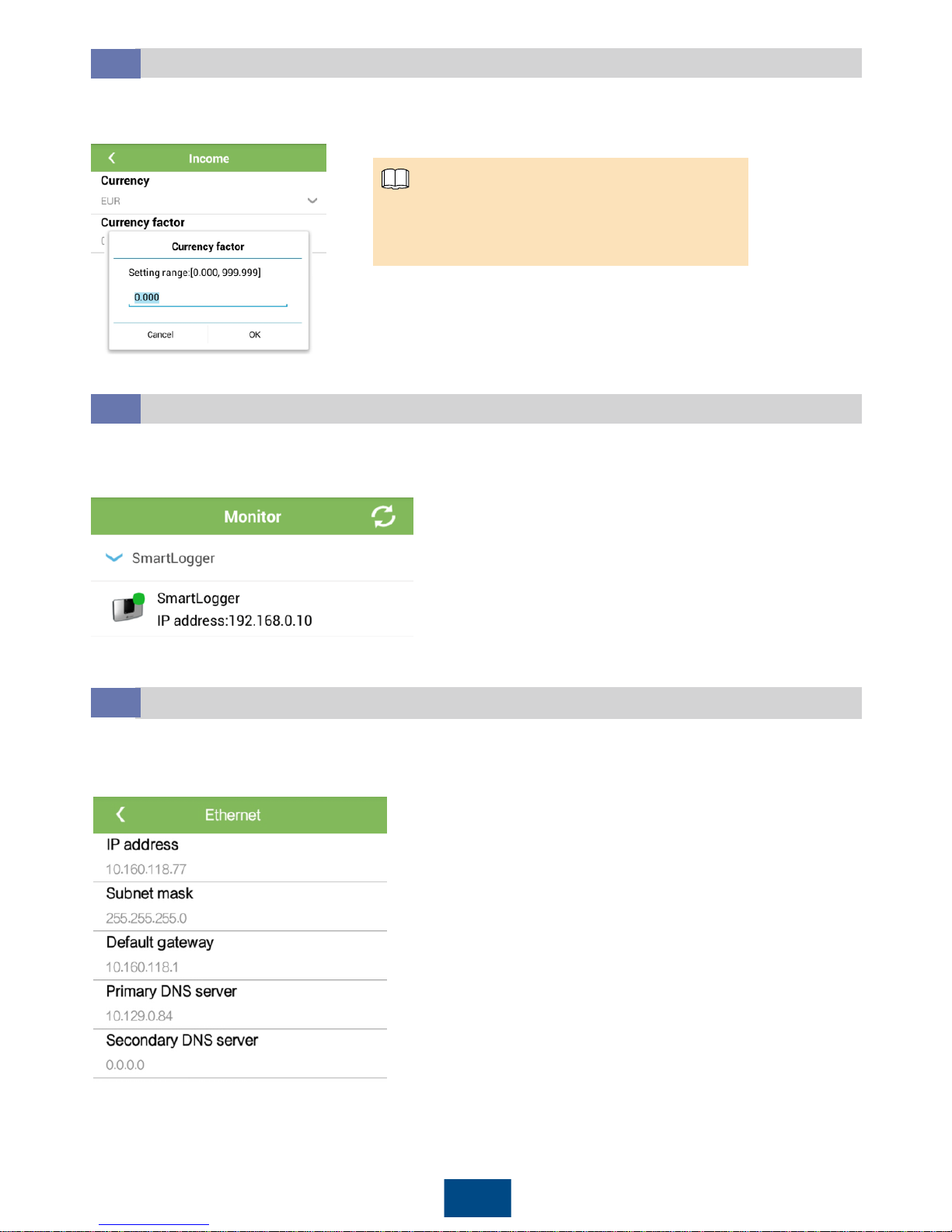
30
Select Monitor at the bottom of the main menu and tap SmartLogger.
Setting Currency Factor
14.2
At the bottom of the main menu, choose More > Settings > User Param > Income. Then set
Currency factor according to the actual situation.
Because of the permission restriction, log in
to the app as a common user or an
advanced user to set Currency factor.
NOTE
Querying the SmartLogger IP Address
14.3
Setting the IP Address
14.4
At the bottom of the main menu, choose More > Settings > Comm. Param. > Ethernet and set
parameters based on site requirements.
Page 32
31
12
FAQ
15
FAQ
The SmartLogger cannot be powered on.
15.1
1. Check that the DC output power cable for the power adapter connects to the 12V IN port on the
SmartLogger.
2. Check whether the power cable is connected to the power adapter.
3. Check whether the power cable is inserted into an AC socket.
4. Replace the power adapter.
5. Contact the supplier or Huawei technical support.
The communication fails in RS485 networking.
15.2
1. RJ45 network port connection: Check whether the RJ45 connector is correctly crimped with
shielded cable wires of various colors connected to the correct pins.
2. Terminal block connection: Check whether the RS485 communications cable is connected to the
correct port of the terminal block.
3. Verify that the RS485 ports of other devices are connected to the correct ports on the
SmartLogger.
4. Check the RS485 communications cable connection. If any cable is loose, drops off, or is
reversely connected, rectify the connection.
5. Power on the SmartLogger and other devices.
6. Check the settings of the RS485 communications parameters.
7. Contact the supplier or Huawei technical support.
The communication fails in PLC networking.
15.3
1. Verify whether the SUN2000s are equipped with a PLC STA.
2. Verify that the power cable of the SmartLogger is properly connected. If the cable is loose or
drops off, reconnect the cable.
3. Check whether the upstream circuit breaker of the AC power cable to the SmartLogger is
switched on.
4. If the built-in PLC module is networked, set Built-in PLC to Enable.
5. Contact the supplier or Huawei technical support.
The SmartLogger cannot find devices.
15.4
1. Check the RS485 communications cable and power cable connections. If any cable is loose,
drops off, or is reversely connected, rectify the connection.
2. Check the settings of the RS485 communications parameters, such as the baud rate and
communications address, are correctly set, and that the SUN2000 address is within the search
range preset on the SmartLogger.
3. Add devices such as the EMI and power meter manually.
4. Contact the supplier or Huawei technical support.
The SmartLogger fails to communicate with the optical port of the
LAN switch.
15.5
1. Check whether the remote LAN switch is powered on. If no, power it on.
2. Check whether the optical module is inserted based on the status of the indicator for the
SmartLogger optical port. If the module is not inserted, insert or reseat it.
3. Check whether the optical jumper is securely connected. If the jumper is loose or disconnected,
reconnect and secure it.
4. Check whether the TX of the SmartLogger optical port connects to the RX of the optical port on
the LAN switch. If the optical jumper is reversely connected, correct the connection.
Page 33

32
How Should I Install the RS485 Signal SPD?
15.6
1. In the smart array controller embedded with the SmartLogger2000-10/10-B/11-B, the RS485 signal
SPD has been factory installed. In a non-smart array controller, an RS485 signal SPD is
recommended if the SmartLogger2000-10/10-B/11-B connects to an outdoor device over the COM
port to enhance the surge protection capability of the SmartLogger. Huawei PowerSA-5KA-15V
RS485 signal SPD is recommended.
2. Each RS485 signal SPD can connect to two COM ports. Each SmartLogger can be configured
with a maximum of three RS485 signal SPDs.
3. When an RS485 signal SPD is to be installed in a non-smart array controller, you are advised to
install it on a guide rail.
4. When determining the installation position, verify that the direct distance between the RS485
signal SPD and the SmartLogger is not greater than 500 mm.
5. If the SmartLogger is installed on a guide rail, the RS485 signal SPD can share the guide rail with
the SmartLogger. In this case, the recommended guide rail length is 600 mm or greater.
6. Secure the guide rail before mounting the RS485 signal SPD.
Clamp the RS485 signal SPD to the guide rail.
How Should I Connect the RS485 Signal SPD?
15.7
The way of connecting two or three RS485 signal SPDs is the same as the way of connecting one
RS485 signal SPD.
NOTE
NOTE
Connecting the Ground Cable
Recommended: an outdoor copper cable with a cross-sectional area of 4 mm2(12 AWG)
Strip 8 mm of the cable insulation layer from one end, and secure the cable to port 3 on the RS485
signal SPD.
Connect the other end of the ground cable to the ground bar.
Recommendation: To enhance the corrosion resistance of a ground terminal, silica gel or paint
might be needed.
NOTICE
Page 34
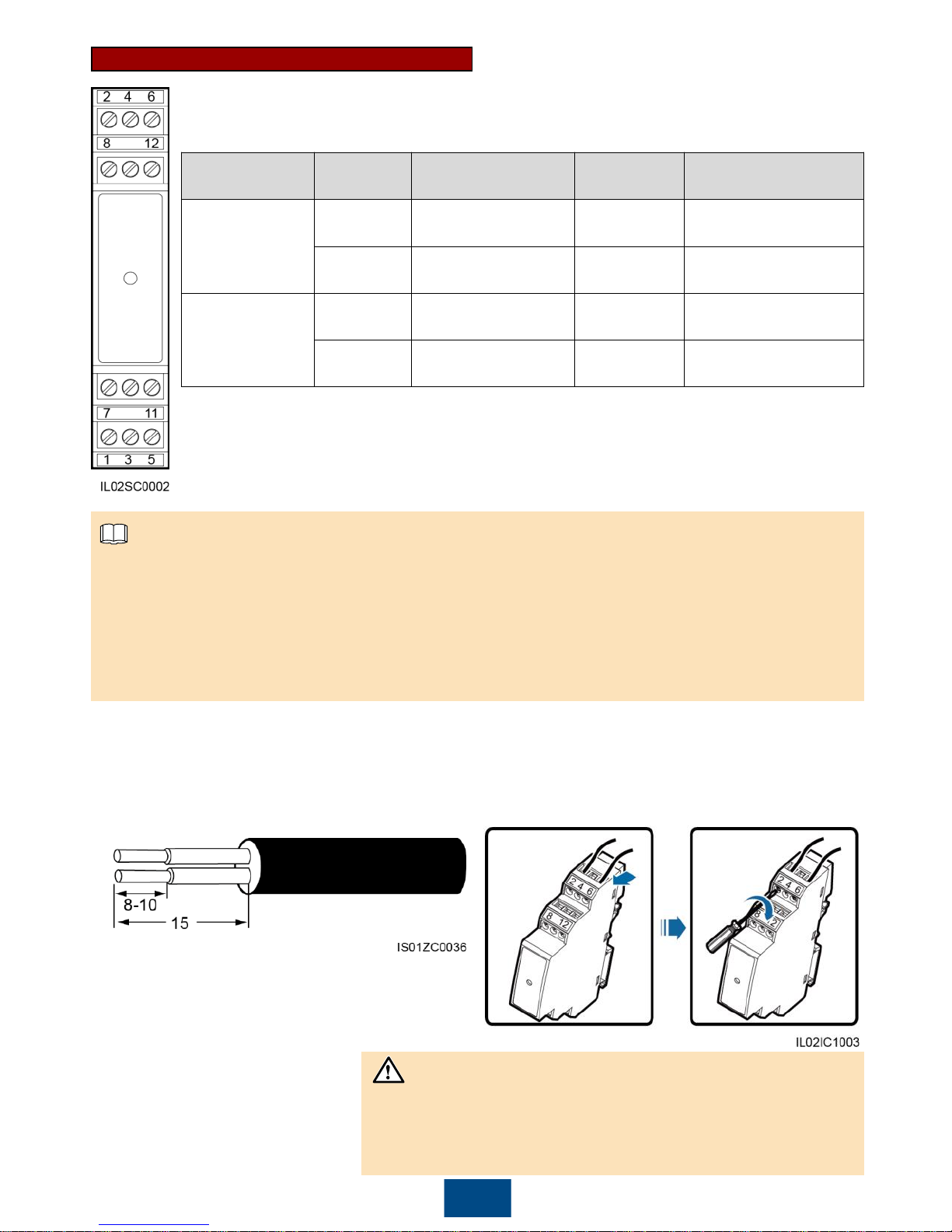
Connecting the Communications Cable
RS485 Surge
Protection Port
Protection
Port
Function Surge Port Function
RS485 surge
protection port 1
2
RS485A, RS485
differential signal+
1
RS485A, RS485
differential signal+
6
RS485B, RS485
differential signal–
5
RS485B, RS485
differential signal –
RS485 surge
protection port 2
8
RS485A, RS485
differential signal+
7
RS485A, RS485
differential signal+
12
RS485B, RS485
differential signal–
11
RS485B, RS485
differential signal–
1. Protection ports connect to the COM ports on the SmartLogger. Port 4 is not connected.
2. Surge ports connect to RS485 ports on other devices. Port 3 is the ground port.
3. Protection ports and surge ports must not be confused.
4. One RS485 signal SPD can protect two COM ports.
5. Protection ports 2 and 6 and surge ports 1 and 5 form an RS485 signal SPD port for protecting
one COM port. Protection ports 8 and 12 and surge ports 7 and 11 form another RS485 signal
SPD port for protecting one more COM port.
NOTE
33
Recommended: two-core or multiple-core cable with a cross-sectional area of 0.5–2.5 mm
2
1. Strip armor from the cable and insulation
layer from the core wires from both ends.
Unit: mm
2. Connect one end of one cable to the
terminal block on the COM port of the
SmartLogger.
3. Connect the other end of the cable
to the protection port of the RS485
signal SPD.
Verify that the COM+ port on the SmartLogger connects to
protection port 2 or 8 on the RS485 signal SPD, and that the
COM– port on the SmartLogger connects to protection port 6 or
12 on the RS485 signal SPD.
NOTICE
Page 35
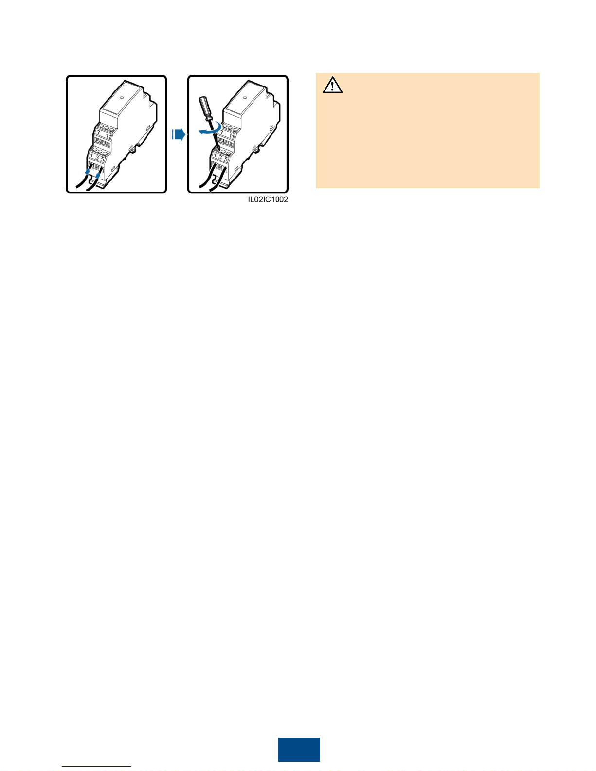
34
4. Connect one end of the other cable to the
surge port of the RS485 signal SPD.
5. Connect the other end of the cable to the
communications port on the device.
Verify that RS485A on the device connects
to surge port 1 or 7 on the RS485 signal
SPD, and that RS485B on the device
connects to surge port 5 or 11 on the
RS485 signal SPD. For the detailed cable
connections, see the instructions about the
connected device.
NOTICE
Page 36

35
Huawei Technologies Co., Ltd.
Huawei Industrial Base, Bantian, Longgang
Shenzhen 518129 People's Republic of China
www.huawei.com
 Loading...