

Page 1

SmartLogger1000A
User Manual
Issue
02
Date
2019-01-15
HUAWEI TECHNOLOGIES CO., LTD.
Page 2

Issue 02 (2019-01-15)
Copyright © Huawei Technologies Co., Ltd.
i
Copyright © Huawei Technologies Co., Ltd. 2019. All rights reserved.
No part of this document may be reproduced or transmitted in any form or by any means without prior
written consent of Huawei Technologies Co., Ltd.
Trademarks and Permissions
and other Huawei trademarks are trademarks of Huawei Technologies Co., Ltd.
All other trademarks and trade names mentioned in this document are the property of their respective
holders.
Notice
The purchased products, services and features are stipulated by the contract made between Huawei and
the customer. All or part of the products, services and features described in this document may not be
within the purchase scope or the usage scope. Unless otherwise specified in the contract, all statements,
information, and recommendations in this document are provided "AS IS" without warranties, guarantees or
representations of any kind, either express or implied.
The information in this document is subject to change without notice. Every effort has been made in the
preparation of this document to ensure accuracy of the contents, but all statements, information, and
recommendations in this document do not constitute a warranty of any kind, express or implied.
Huawei Technologies Co., Ltd.
Address:
Huawei Industrial Base
Bantian, Longgang
Shenzhen 518129
People's Republic of China
Website:
http://e.huawei.com
Page 3

SmartLogger1000A
User Manual
About This Document
Issue 02 (2019-01-15)
Copyright © Huawei Technologies Co., Ltd.
ii
Purpose
Symbol
Description
Indicates an imminently hazardous situation which, if not
avoided, will result in serious injury or death.
Indicates a potentially hazardous situation which, if not
avoided, could result in serious injury or death.
Indicates a potentially hazardous situation which, if not
avoided, may result in minor or moderate injury.
Indicates a potentially hazardous situation which, if not
avoided, could result in equipment damage, data loss,
performance deterioration, or unanticipated results.
NOTICE is used to address practices not related to personal
injury.
Calls attention to important information, best practices and
tips.
NOTE is used to address information not related to personal
injury, equipment damage, and environment deterioration.
This document introduces the SmartLogger1000A (SmartLogger for short) in terms of
installation, electrical connections, system operation and maintenance, and troubleshooting.
Understand the SmartLogger features, functions, and safety precautions provided in this
document before installing and operating the SmartLogger.
Intended Audience
About This Document
This document is intended for photovoltaic (PV) plant operators and qualified electrical
technicians.
Symbol Conventions
The symbols that may be found in this document are defined as follows.
Page 4

SmartLogger1000A
User Manual
About This Document
Issue 02 (2019-01-15)
Copyright © Huawei Technologies Co., Ltd.
iii
Change History
Changes between document issues are cumulative. The latest document issue contains all
updates made in previous issues.
Issue 02 (2019-01-15)
Updated 6.4.5 Setting Export Limitation Parameters.
Added 6.4.6 Setting DRM parameters.
Updated 7.4.3 Sending a System Maintenance Command.
Issue 01 (2018-11-20)
This issue is used for first office application (FOA).
Page 5

SmartLogger1000A
User Manual
Contents
Issue 02 (2019-01-15)
Copyright © Huawei Technologies Co., Ltd.
iv
Contents
About This Document .................................................................................................................... ii
1 Safety Precautions ......................................................................................................................... 1
2 Product Overview ......................................................................................................................... 3
2.1 Product Model .............................................................................................................................................................. 3
2.2 Overview ...................................................................................................................................................................... 5
2.3 Appearance ................................................................................................................................................................... 7
3 Device Installation ...................................................................................................................... 12
3.1 Checking Before Installation ...................................................................................................................................... 12
3.2 Tools ........................................................................................................................................................................... 12
3.3 Installation Requirements ........................................................................................................................................... 14
3.4 Installing the SmartLogger ......................................................................................................................................... 14
3.5 Installing a Power Adapter .......................................................................................................................................... 16
4 Cable Connections ...................................................................................................................... 18
4.1 Preparing Cables ......................................................................................................................................................... 18
4.2 Connecting a PE Cable ............................................................................................................................................... 18
4.3 Connecting an RS485 communications cable ............................................................................................................. 19
4.4 Connecting an AC Power Cable (PLC) ...................................................................................................................... 21
4.5 Connecting an AI Signal Cable ................................................................................................................................... 23
4.6 Connecting a DI Signal Cable .................................................................................................................................... 24
4.7 Connecting a DO Signal Cable ................................................................................................................................... 25
4.8 Connecting an Ethernet Cable .................................................................................................................................... 25
4.9 Installing a SIM Card and a 4G Antenna .................................................................................................................... 26
5 System Operation ........................................................................................................................ 28
5.1 Check Before Power-On ............................................................................................................................................. 28
5.2 Powering On the System............................................................................................................................................. 28
6 WebUI Operations ...................................................................................................................... 30
6.1 Introduction to WebUI ................................................................................................................................................ 30
6.1.1 WebUI Layout ................................................................................................................................ .......................... 30
6.1.2 Icon Description ....................................................................................................................................................... 31
6.1.3 WebUI Menu ............................................................................................................................................................ 32
Page 6

SmartLogger1000A
User Manual
Contents
Issue 02 (2019-01-15)
Copyright © Huawei Technologies Co., Ltd.
v
6.2 Device Commissioning ............................................................................................................................................... 39
6.2.1 Preparations and WebUI Login ................................................................................................................................ 39
6.2.2 Performing Deployment Wizard .............................................................................................................................. 41
6.3 Parameter Settings ...................................................................................................................................................... 42
6.3.1 Setting User Parameters ........................................................................................................................................... 42
6.3.2 Setting Parameters for Connecting to the NMS ....................................................................................................... 44
6.3.3 Setting RS485 Communications Parameters ........................................................................................................... 49
6.3.4 Setting Slave SmartLogger Parameters.................................................................................................................... 51
6.3.5 Setting PLC CCO Parameters .................................................................................................................................. 51
6.3.6 Setting SUN2000 Parameters .................................................................................................................................. 55
6.3.6.1 Running Parameters (Advanced User) .................................................................................................................. 56
6.3.6.2 Running Parameters (Special User) ...................................................................................................................... 61
6.3.7 Setting PID Module Parameters................................................................ ............................................................... 66
6.3.8 Setting Power Meter Parameters .............................................................................................................................. 69
6.3.8.1 Setting DL/T645 Power Meter Parameters ........................................................................................................... 69
6.3.8.2 Setting Modbus-RTU Meter Parameters ................................ ................................................................ ............... 71
6.3.9 Setting EMI Parameters ........................................................................................................................................... 73
6.3.9.1 Setting Modbus-RTU EMI Parameters ................................................................................................................. 73
6.3.9.2 Setting AI EMI Parameters ................................................................................................................................... 77
6.3.10 Setting IEC103 Device Parameters ........................................................................................................................ 78
6.3.11 Setting Parameters for a Custom Device ............................................................................................................... 81
6.4 Power Grid Scheduling ............................................................................................................................................... 83
6.4.1 Power Adjustment Description ................................................................................................................................ 83
6.4.2 Setting Active Power Control .................................................................................................................................. 84
6.4.3 Setting Reactive Power Control ............................................................................................................................... 87
6.4.4 Setting Remote Shutdown over Dry Contacts ......................................................................................................... 95
6.4.5 Setting Export Limitation Parameters ...................................................................................................................... 96
6.4.6 Setting DRM parameters ....................................................................................................................................... 100
7 Device Maintenance ................................................................................................................. 103
7.1 Routine Maintenance ................................................................................................................................ ................ 103
7.2 Troubleshooting ........................................................................................................................................................ 103
7.3 Alarm List ................................................................................................................................................................. 105
7.4 WebUI Maintenance Operations ............................................................................................................................... 109
7.4.1 Upgrading the Device Firmware Version ............................................................................................................... 109
7.4.2 Configuring Security Parameters ................................................................ ........................................................... 110
7.4.3 Sending a System Maintenance Command ............................................................................................................ 111
7.4.4 Exporting Device Logs .......................................................................................................................................... 113
7.4.5 Starting an Onsite Test ........................................................................................................................................... 113
7.4.6 Managing the Inverter License .............................................................................................................................. 114
7.4.7 Collecting Performance Data ................................................................................................................................. 116
7.4.8 Adjusting the Total Energy Yield ........................................................................................................................... 116
Page 7

SmartLogger1000A
User Manual
Contents
Issue 02 (2019-01-15)
Copyright © Huawei Technologies Co., Ltd.
vi
7.5 Device Disposal ........................................................................................................................................................ 116
8 FAQ .............................................................................................................................................. 117
8.1 How to Connect the SmartLogger to the SUN2000 App? ........................................................................................ 117
8.2 How Do I Set FTP Parameters? ................................................................................................................................ 121
8.3 How Do I Set Email Parameters? ............................................................................................................................. 123
8.4 How Do I Change the SSID and Password of the Built-in WLAN? ......................................................................... 125
8.5 How Do I Use DI Ports? ........................................................................................................................................... 126
8.6 How Do I Use DO Ports? ......................................................................................................................................... 127
8.7 How Do I Use the USB Port? ................................................................................................................................... 128
8.8 How Can I Change a Device Name? ........................................................................................................................ 130
8.9 How Do I Change the Communication Address? ..................................................................................................... 130
8.10 How Do I Export Inverter Parameters?................................................................................................................... 131
8.11 How Do I Clear Alarms? ......................................................................................................................................... 131
8.12 How Do I Enable the AI1 Port to Detect SPD Alarms? .......................................................................................... 132
8.13 What Types of Electricity Meters and EMIs does the SmartLogger Support?........................................................ 132
9 Technical Specifications .......................................................................................................... 135
A Product User Lists .................................................................................................................... 138
B Acronyms and Abbreviations ................................................................................................ 139
Page 8
SmartLogger1000A
User Manual
1 Safety Precautions
Issue 02 (2019-01-15)
Copyright © Huawei Technologies Co., Ltd.
1
General Safety Precautions
Before performing operations, read through this manual and follow all the precautions to
prevent accidents. The "DANGER", "WARNING", "CAUTION", and "NOTICE" marks
in this document do not represent all the safety instructions. They are only supplements to
the safety instructions.
Only certified electricians are allowed to install, connect cables for, commission, maintain,
and troubleshoot the SmartLogger, and they must understand basic safety precautions to
avoid hazards.
1 Safety Precautions
Disclaimer
To ensure safety of humans and the equipment, pay attention to the safety symbols on the
equipment and all the safety instructions in this document. The safety precautions provided in
this document do not cover all the safety precautions. Huawei shall not be liable for any
consequence caused by the violation of the safety operation regulations and design,
production, and usage standards.
Huawei shall not be liable for any consequence caused by any of the following events:
Damage during transportation
Storage conditions that do not meet the requirements specified in this document
Incorrect storage, installation, or use
Installation or use by unqualified personnel
Failure to obey the operation instructions and safety precautions in this document
Operation in extreme environments which are not covered in this document
Unauthorized modifications to the product or software code or removal of the product
Device damage due to abnormal natural factors (force majeure, such as earthquake,
lightning strike, and fire)
Warranty expiration without extension of the warranty service
Installation or use in environments which are not specified in international standards
Page 9

SmartLogger1000A
User Manual
1 Safety Precautions
Issue 02 (2019-01-15)
Copyright © Huawei Technologies Co., Ltd.
2
Personnel Requirements
Only certified electricians are allowed to install, connect cables for, commission, maintain,
troubleshoot, and replace the SmartLogger. Operators need to meet the following
requirements:
Be properly trained.
Read through this manual and master related safety precautions.
Be familiar with related safety regulations on electrical systems.
Understand the components and functioning of a grid-tied PV power system and relevant
local standards.
Wear proper PPE all the time.
Labels
Do not scrawl, damage, or block any label or nameplate on the SmartLogger.
Installation
Do not install the SmartLogger with the power on.
Install the SmartLogger in an environment with good ventilation.
Ensure that the heat dissipation holes of the SmartLogger are not blocked.
Install the SmartLogger in a dedicated area.
During installation, do not touch any component inside the enclosure except the external
ports of the SmartLogger.
Ensure that the cables of Smartlogger are connected through the cable groove to avoid
the cables being exposed.
Maintenance and Replacement
A faulty SmartLogger requires overall maintenance. Contact the dealer if the
SmartLogger is faulty.
With sufficient knowledge of this document, maintain the SmartLogger by using proper
tools and testing equipment.
Observe ESD precautions and wear ESD gloves during maintenance.
The device has multiple inputs. Switch off all inputs before maintenance.
Page 10
SmartLogger1000A
User Manual
2 Product Overview
Issue 02 (2019-01-15)
Copyright © Huawei Technologies Co., Ltd.
3
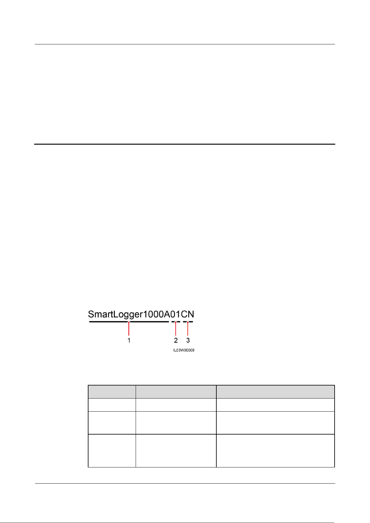
2.1 Product Model
No.
Meaning
Description
1
Product name
SmartLogger1000A: data collector
2
Feature ID
01: The PLC function is optional.
02: The PLC function is not supported.
3
Region CN: China
JP: Japan
EU: Europe
Model Description
This document involves the following product models:
SmartLogger1000A01CN
SmartLogger1000A02JP
SmartLogger1000A01EU
SmartLogger1000A01UK
SmartLogger1000A01AU
SmartLogger1000A02KR
SmartLogger1000A01US
2 Product Overview
Figure 2-1 Model
Table 2-1 Model description
Page 11
SmartLogger1000A
User Manual
2 Product Overview
Issue 02 (2019-01-15)
Copyright © Huawei Technologies Co., Ltd.
4
No.
Meaning
Description
UK: United Kingdom
AU: Australia
KR: South Korea
US: United States
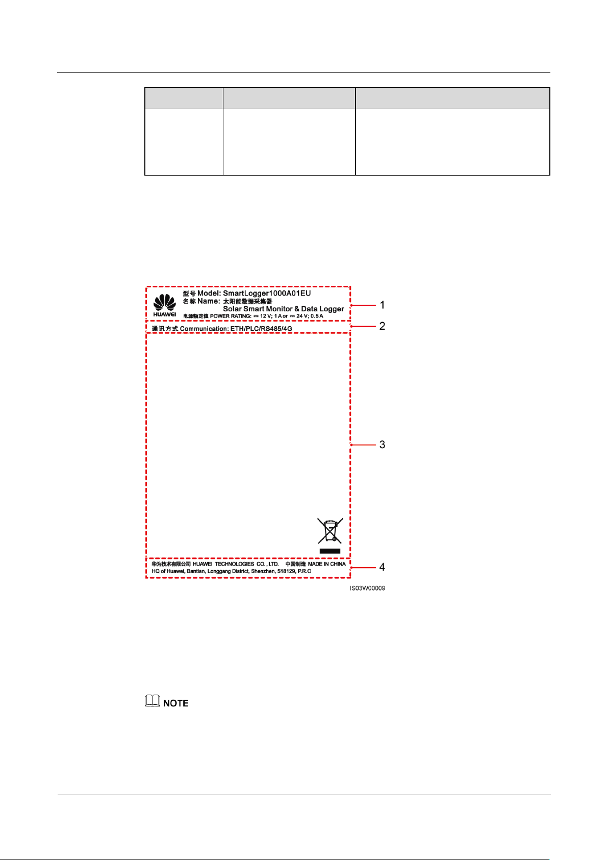
(1) Trademark, product model, and power
rating
(2) Communications mode
(3) Compliance symbols
(4) Company name and place of
manufacture
Model Identification
You can view the SmartLogger model on the nameplate on the enclosure.
Figure 2-2 Nameplate
The nameplate figure is for reference only.
Page 12

SmartLogger1000A
User Manual
2 Product Overview
Issue 02 (2019-01-15)
Copyright © Huawei Technologies Co., Ltd.
5
Table 2-2 Compliance symbols
Symbol
Name
Meaning
EU waste electrical and electronic
equipment (WEEE) mark
The SmartLogger must not be
disposed of as domestic waste.
2.2 Overview
Function
The SmartLogger monitors and manages the PV power system. It converges all ports,
converts protocols, collects and stores data, and centrally monitors and maintains the devices
in the PV power system.
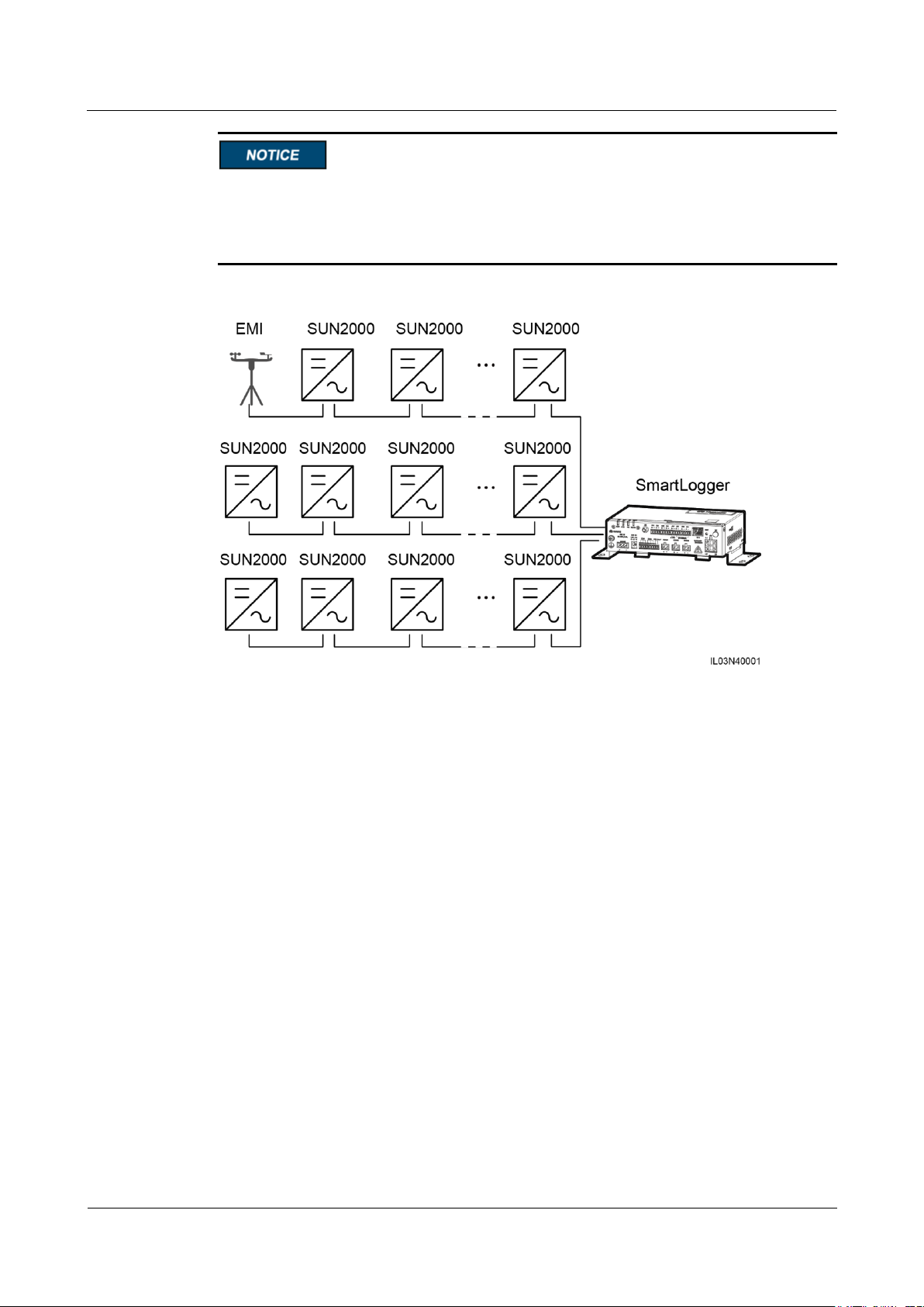
Network Application
The SmartLogger applies to a PV power system. It supports the following:
Local operations on the SmartLogger using the mobile phone app through the built-in
WLAN
RS485 networking, which enables the SmartLogger to connect to:
− Huawei devices such as inverters and PID modules
− Third-party inverters, environment monitoring instrument (EMIs), box-type
transformers, and power meters that use the standard Modbus-RTU protocol
− Power meters that use the DL/T645 protocol
− Devices that use the standard IEC103 protocol
PLC networking, which enables the SmartLogger to connect to inverters and the
PID-PVBOX.
Ethernet, 2G, 3G, or 4G networking, which allows the SmartLogger to connect to a
network management system (NMS) that uses the Modbus TCP or IEC104 protocol
When using the IEC104 protocol,4G/3G/2G networking is not supported.
Page 13

SmartLogger1000A
User Manual
2 Product Overview
Issue 02 (2019-01-15)
Copyright © Huawei Technologies Co., Ltd.
6
Figure 2-3 Network application
Page 14
SmartLogger1000A
User Manual
2 Product Overview
Issue 02 (2019-01-15)
Copyright © Huawei Technologies Co., Ltd.
7
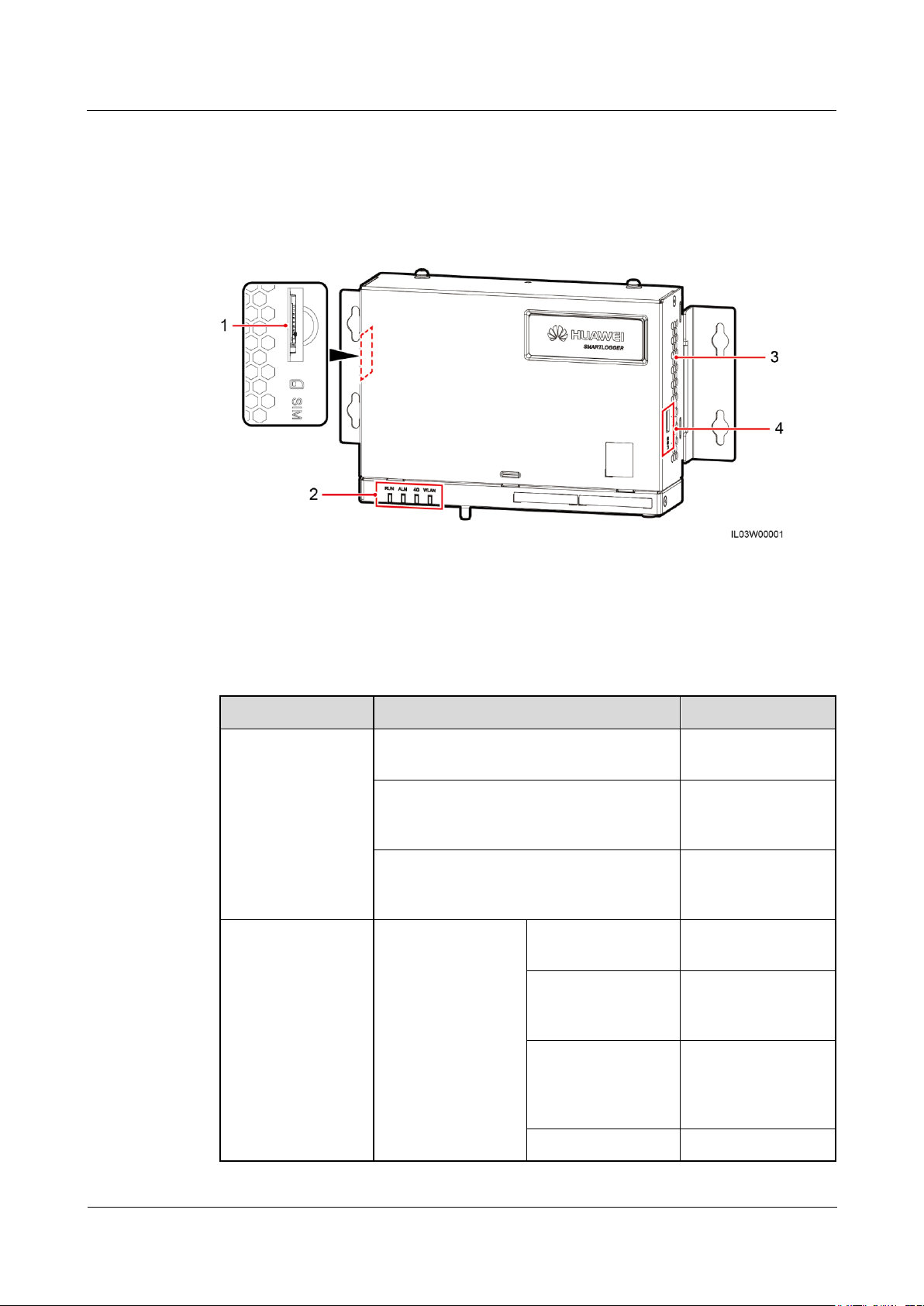
2.3 Appearance
(1) SIM card slot
(2) LED indicators
(3) Heat dissipation holes
(4) USB port
Indicator
Status
Description
Running indicator
(RUN)
Green off
The SmartLogger is
not powered on.
Blinking green at short intervals (on for
0.125s and then off for 0.125s)
The communication
with the encrypted
NMS is interrupted.
Blinking green at long intervals (on for 1s
and then off for 1s)
The connection with
the encrypted NMS
is normal.
Alarm/maintenance
indicator (ALM)a
Alarm status
Red off
No system alarm is
raised.
Blinking red at long
intervals (on for 1s
and then off for 4s)
The system raises a
warning alarm.
Blinking red at short
intervals (on for 0.5s
and then off for
0.5s)
The system raises a
minor alarm.
Steady red
The system raises a
Front View
Figure 2-4 Front view
Table 2-3 LED indicator description
Page 15

SmartLogger1000A
User Manual
2 Product Overview
Issue 02 (2019-01-15)
Copyright © Huawei Technologies Co., Ltd.
8
Indicator
Status
Description
major alarm.
Maintenance status
Green off
No local
maintenance is
underwayb.
Blinking green at
long intervals (on
for 1s and then off
for 1s)
Local maintenance is
in progress.
Steady green
Local maintenance
succeeds.
Blinking green at
short intervals (on
for 0.125s and then
off for 0.125s)
Local maintenance
fails.
4G/3G/2G indicator
(4G)
Blinking green at short intervals (on for
0.125s and then off for 0.125s)
4G/3G/2G is not
connected.
Blinking green at long intervals (on for 1s
and then off for 1s)
Succeeds in dialing
through 4G/3G/2G
network.
WLAN indicator
(WLAN)
Green off
No mobile phone is
connected.
Blinking green at long intervals (on for 1s
and then off for 1s)
A mobile phone is
successfully
connected.
a: If an alarm and local maintenance happen concurrently, the alarm/maintenance indicator
shows the near-end maintenance state first. After the USB flash drive is removed, the
indicator shows the alarm state.
b: Local maintenance refers to operations performed by connecting a USB flash drive to the
SmartLogger USB port, such as full data import and export using a USB flash drive.
Page 16
SmartLogger1000A
User Manual
2 Product Overview
Issue 02 (2019-01-15)
Copyright © Huawei Technologies Co., Ltd.
9
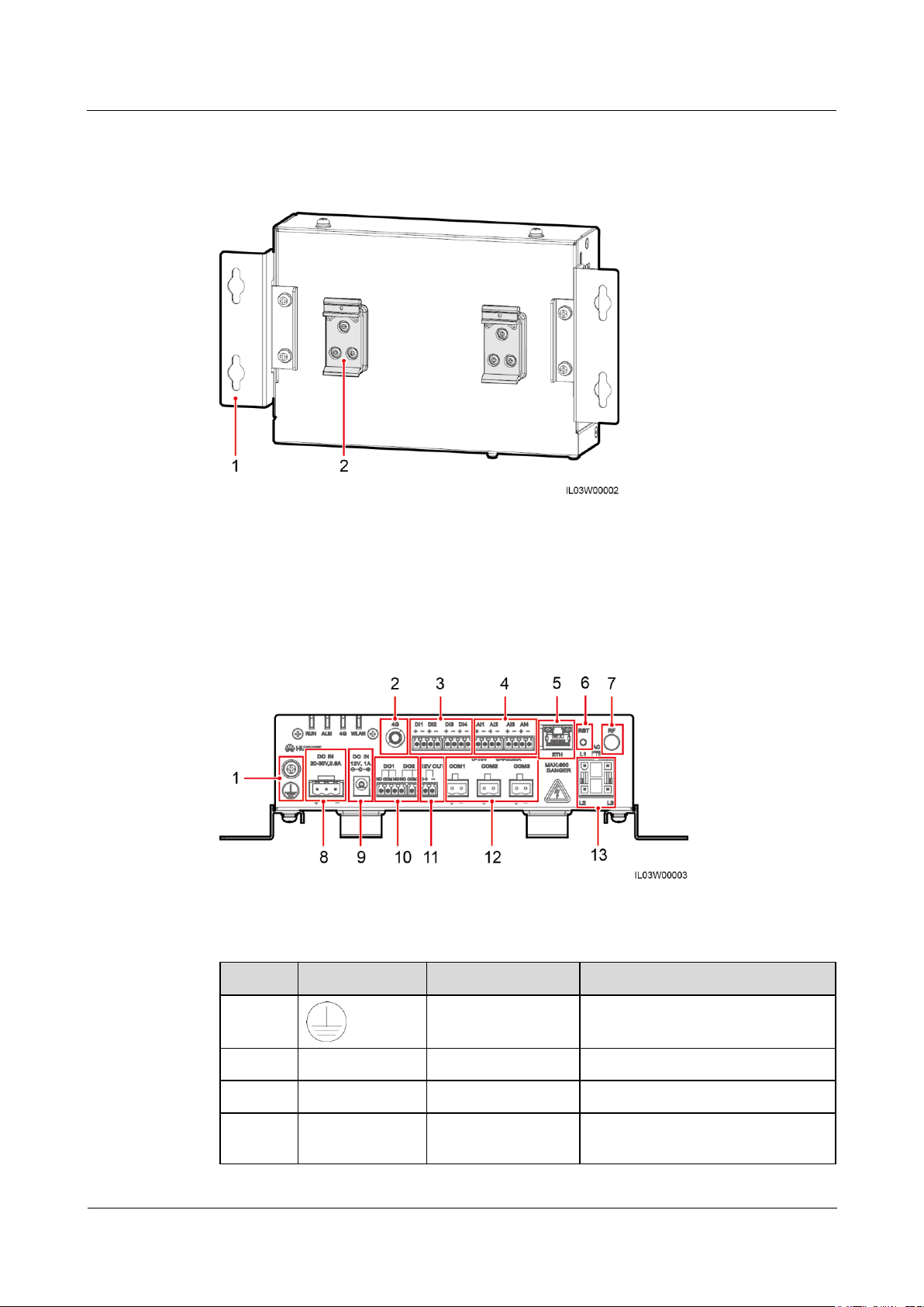
Rear View
(1) Mounting ear
(2) Guide rail clamp
No.
Port
Function
Description
1 External grounding
N/A
2
4G
4G antenna port
N/A
3
DI1–DI4
Digital input
Connects to a dry contact input.
4
AI1–AI4
Analog input
AI1 detects 0–10 V signals.
AI2 to AI4 detect 4–20 mA or
Figure 2-5 Rear view
Bottom View
Figure 2-6 Bottom view
Table 2-4 Port description
Page 17
SmartLogger1000A
User Manual
2 Product Overview
Issue 02 (2019-01-15)
Copyright © Huawei Technologies Co., Ltd.
10
No.
Port
Function
Description
0–20 mA signals. The signal
current range can be configured
on the WebUI or mobile phone
app.
5
ETH
Ethernet electrical
port
Connects to an Ethernet switch,
router, or PC.
6
RST
Button
To perform a restart, hold down
the button for 3s to 10s.
To restore to the default IP
address 192.168.0.10, hold down
the button for more than 10s.
The IP address will be restored
within 5minutes.
7
RF
Reserved
N/A
8
DC IN 20–30
V,0.8 A
20–30 V DC input
N/A
9
DC IN 12 V,1 A
12 V power input
N/A
10
DO1–DO2
Digital output
NO and COM are normally open
contacts, and NC and COM are
normally closed contacts. The
maximum signal voltage of 12 V is
supported.
11
12 V OUT
12 V power output
N/A
12
COM1–COM3
RS485
communication
N/A
13
AC
AC power cable port
Use this port when the PLC function
is required for power line
communication between the
SmartLogger and the inverter. If the
PLC function is not required, you
do not need to connect a cable to
this port.
Page 18

SmartLogger1000A
User Manual
2 Product Overview
Issue 02 (2019-01-15)
Copyright © Huawei Technologies Co., Ltd.
11
Dimensions
Figure 2-7 Dimensions
Page 19
SmartLogger1000A
User Manual
3 Device Installation
Issue 02 (2019-01-15)
Copyright © Huawei Technologies Co., Ltd.
12
3 Device Installation
Check Item
Criteria
Outer packaging
The outer package is intact. If it is damaged or abnormal, do not unpack it and
contact your dealer.
Deliverables
Check the quantity of deliverables against the Packing List in the packing case. If
any component is missing or damaged, contact your dealer.
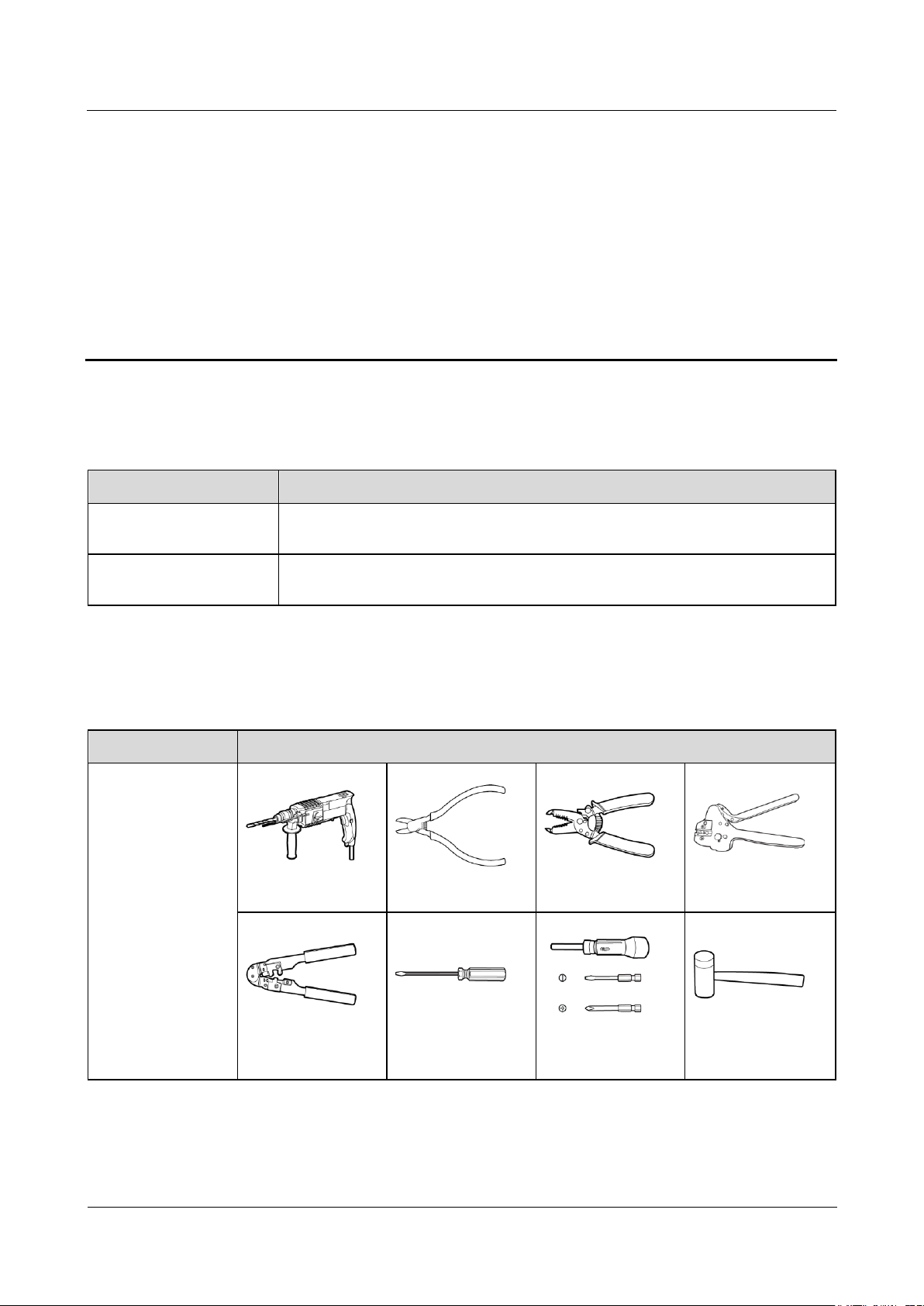
Type
Tool
Installation
Hammer drill
Diagonal pliers
Wire stripper
Crimping tool
RJ45 crimping tool
Flat-head
screwdriver
Torque screwdriver
Rubber mallet
3.1 Checking Before Installation
3.2 Tools
Page 20
SmartLogger1000A
User Manual
3 Device Installation
Issue 02 (2019-01-15)
Copyright © Huawei Technologies Co., Ltd.
13
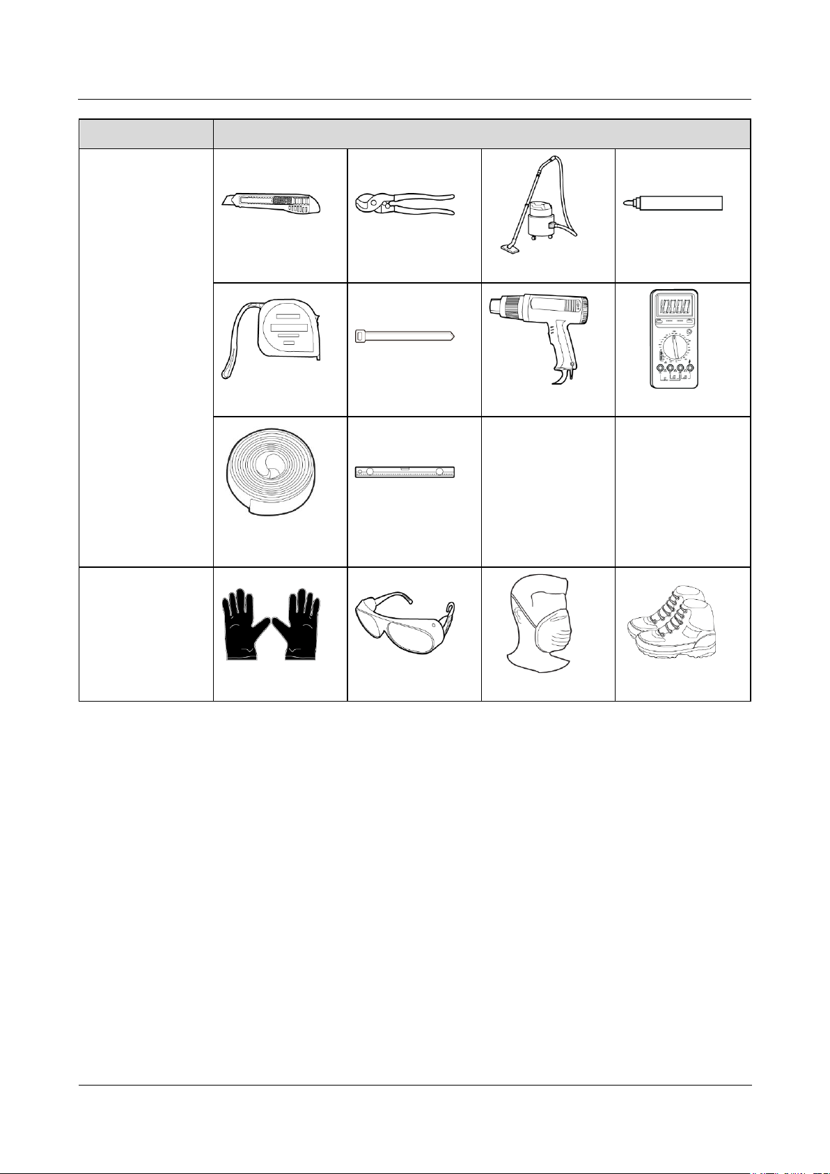
Type
Tool
Utility knife
Cable cutter
Vacuum cleaner
Marker
Measuring tape
Cable tie
Heat gun
Multimeter
Heat shrink tubing
Bubble or digital
level
-
-
PPE
Safety gloves
Safety goggles
Anti-dust respirator
Safety shoes
Page 21
SmartLogger1000A
User Manual
3 Device Installation
Issue 02 (2019-01-15)
Copyright © Huawei Technologies Co., Ltd.
14
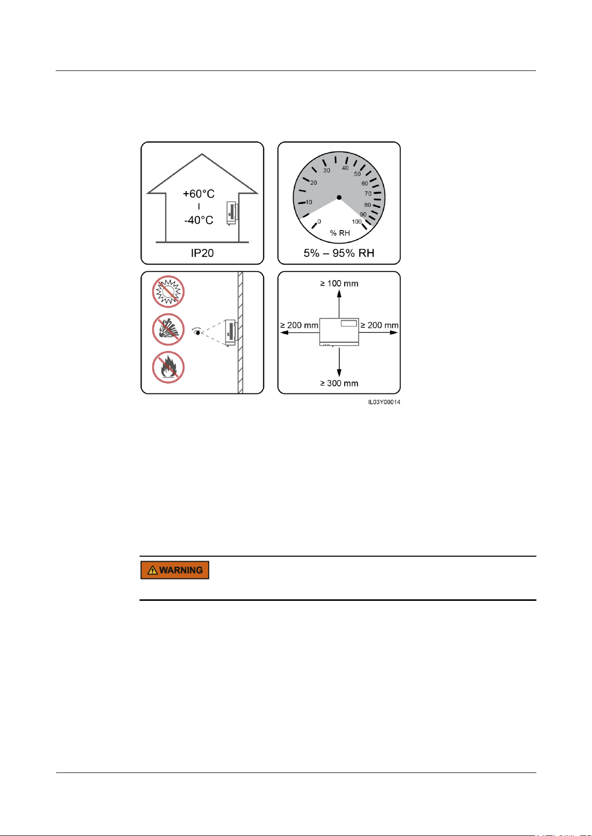
3.3 Installation Requirements
Figure 3-1 Installation position
3.4 Installing the SmartLogger
The SmartLogger can be wall-mounted or guide rail-mounted.
Wall-Mounted Installation
Avoid drilling holes in the water pipes and power cables buried in the wall.
Page 22

SmartLogger1000A
User Manual
3 Device Installation
Issue 02 (2019-01-15)
Copyright © Huawei Technologies Co., Ltd.
15
Figure 3-2 Wall-mounted installation
Guide Rail-Mounted Installation
Prepare a 35 mm standard guide rail by yourself. Ensure that the guide rail:
Has sufficient length for securing the SmartLogger. The recommended effective length is
200 mm or greater.
Has been secured before you install the SmartLogger.
Figure 3-3 Guide rail-mounted installation
Page 23

SmartLogger1000A
User Manual
3 Device Installation
Issue 02 (2019-01-15)
Copyright © Huawei Technologies Co., Ltd.
16
3.5 Installing a Power Adapter
A power adapter can be installed on a wall or flat surface.
If a power adapter is needed for the SmartLogger, install the adapter on the left side of the
SmartLogger, and keep the AC power cable port upward.
Wall-Mounted Installation
Avoid drilling holes in the water pipes and power cables buried in the wall.
Figure 3-4 Wall-mounted installation
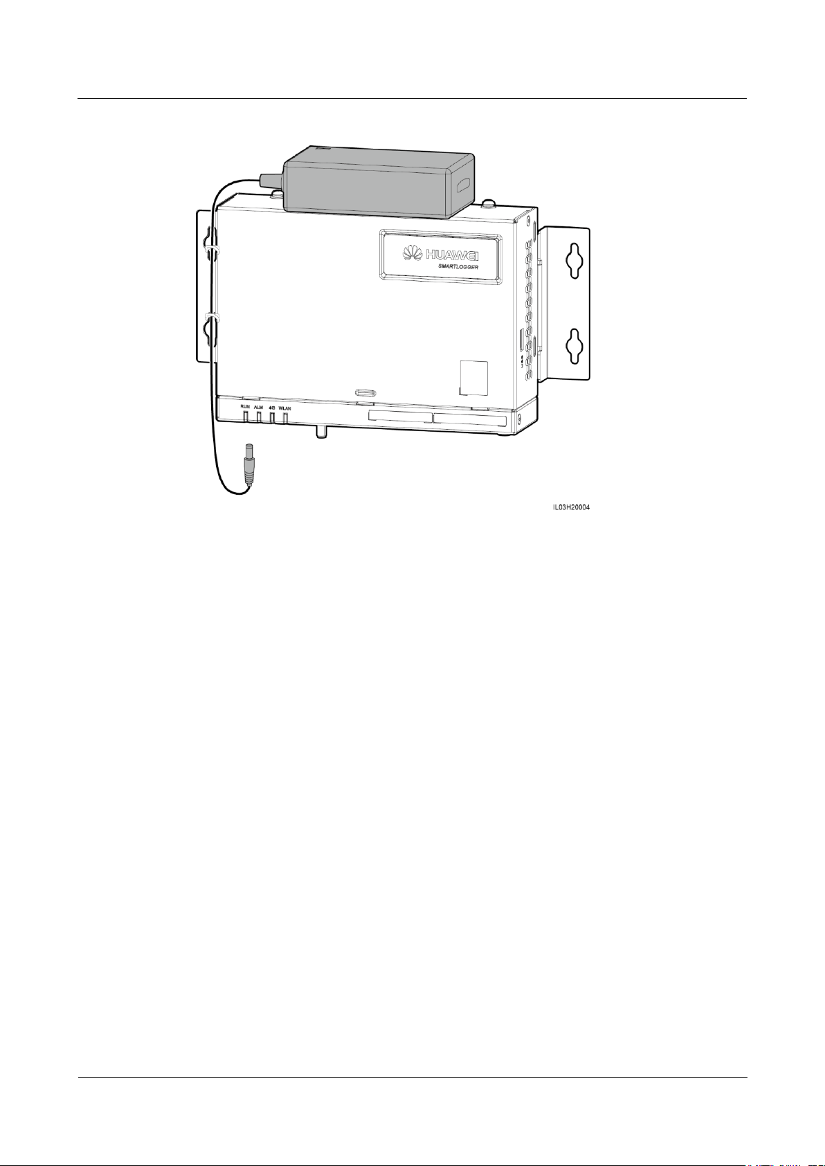
Flat Surface-Mounted Installation
Install the power adapter on a flat surface. This section describes how to install the power
adapter on the top of the SmartLogger.
Step 1 Place the power adapter horizontally on the top of the SmartLogger.
Ensure that the power adapter indicator faces upward or outward.
Step 2 Plan the route for the power adapter cable and bind the cable to the heat dissipation holes of
the SmartLogger.
Page 24
SmartLogger1000A
User Manual
3 Device Installation
Issue 02 (2019-01-15)
Copyright © Huawei Technologies Co., Ltd.
17
Figure 3-5 Flat surface-mounted installation
----End
Page 25

SmartLogger1000A
User Manual
4 Cable Connections
Issue 02 (2019-01-15)
Copyright © Huawei Technologies Co., Ltd.
18
4.1 Preparing Cables
Type
Recommended Cable Specifications
PE cable
Outdoor copper-core cable with a cross-sectional area of 4–6 mm2 or
12–10 AWG
RS485
communication
s cable
Two-core or multiple-core cable with a cross-sectional area of 1.5 mm2
or 20 AWG
AI, DI, and DO
signal cables
Two-core or multiple-core cable with a cross-sectional area of 1.5 mm2
or 20 AWG
PLC
communication
s cable
(optional)
Delivered with the SmartLogger. The length is 1.5 m.
Network cable
Delivered with the SmartLogger. The length is 2.2 m.
Power cable
(optional)
Two-core or multiple-core cable with a cross-sectional area of 1.5 mm2
or 20 AWG
4 Cable Connections
If the delivered network cable is too short, use a shielded network cable of CAT 5E or higher
specifications. The cable length should not exceed 100 m.
4.2 Connecting a PE Cable
Procedure
Step 1 Connect the PE cable.
Page 26

SmartLogger1000A
User Manual
4 Cable Connections
Issue 02 (2019-01-15)
Copyright © Huawei Technologies Co., Ltd.
19
Figure 4-1 Connecting a PE cable
Port
Silk Screen
Description
COM1–COM3
+
RS485A, RS485 differential
signal+
-
RS485B, RS485 differential
signal–
----End
4.3 Connecting an RS485 communications cable
Context
The SmartLogger can connect to RS485 communications devices such as the inverter,
EMI, power meter, and PID module over COM ports.
Ensure that RS485+ is connected to COM+ of the SmartLogger and RS485– is
connected to the COM- of the SmartLogger.
Figure 4-2 COM ports
Page 27

SmartLogger1000A
User Manual
4 Cable Connections
Issue 02 (2019-01-15)
Copyright © Huawei Technologies Co., Ltd.
20
Procedure
Step 1 Connect the RS485 communications cable.
Figure 4-3 Connecting an RS485 communications cable
Step 2 If devices need to be cascaded, cascade the devices and then connect them to the
SmartLogger.
Page 28
SmartLogger1000A
User Manual
4 Cable Connections
Issue 02 (2019-01-15)
Copyright © Huawei Technologies Co., Ltd.
21
A maximum of 80 devices can connect to a single SmartLogger. You are advised to
connect less than 30 devices to each RS485 route.
The baud rate, communications protocol, and parity mode of all devices on an RS485
cascading link must be the same as those of the COM port on the SmartLogger.
Figure 4-4 Cascading connection
----End
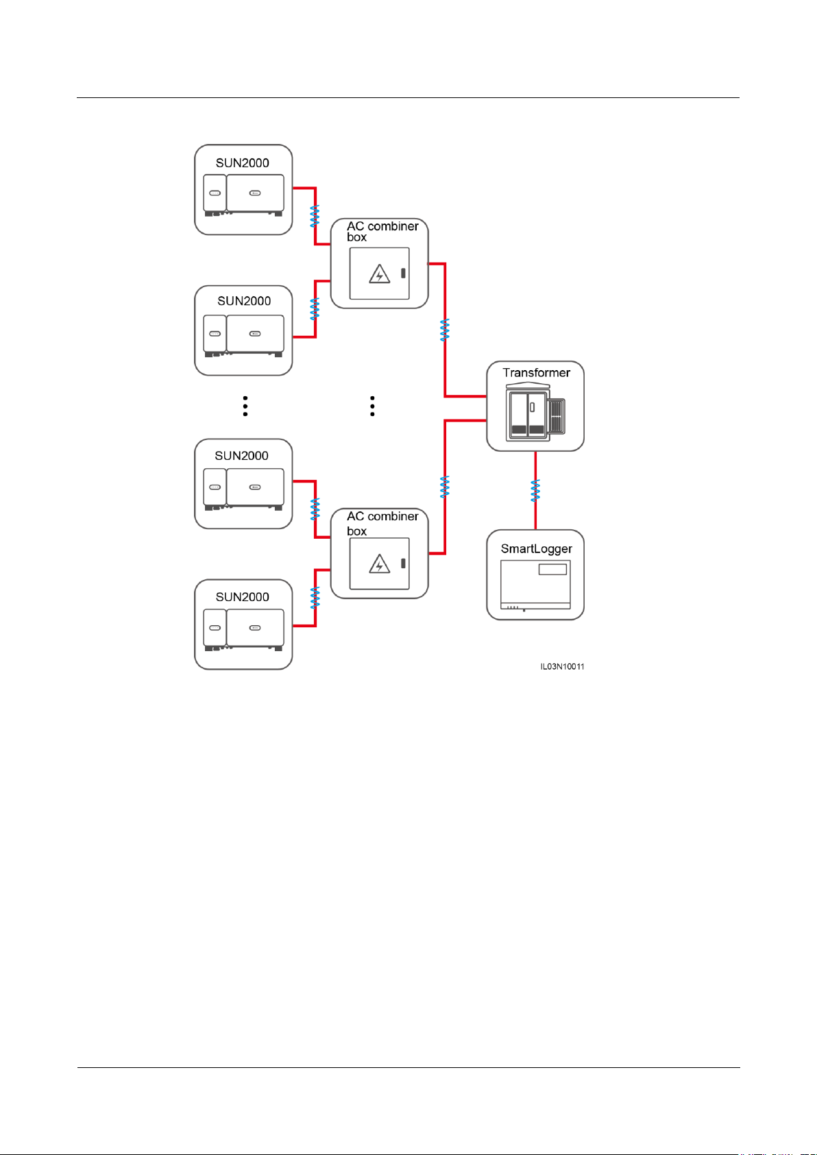
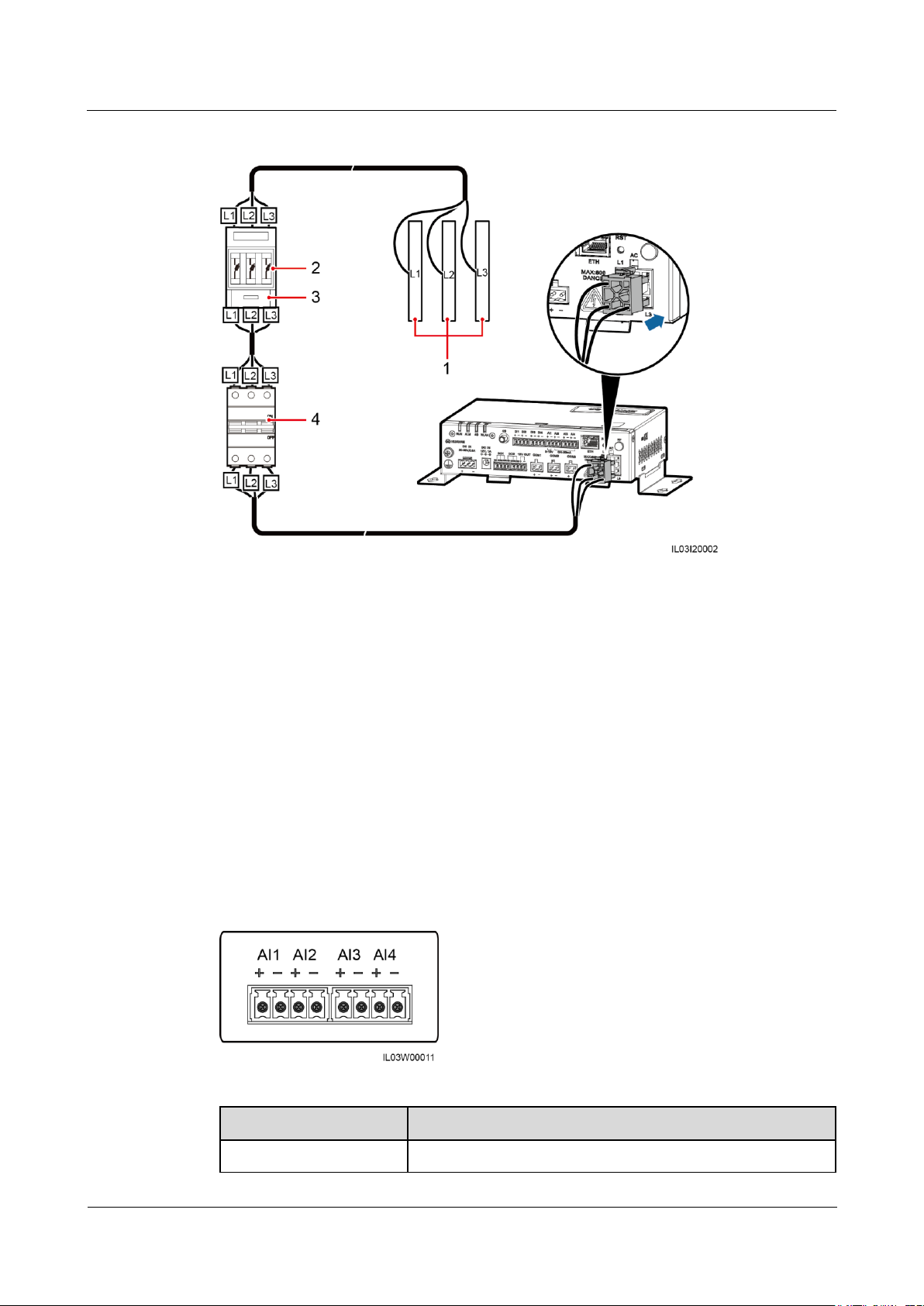
4.4 Connecting an AC Power Cable (PLC)
Context
If both the SmartLogger and the inverter support PLC, the SmartLogger can be connected to
the inverter through an AC power cable. In this case, you do not need to connect the RS485
communications cable of the inverter.
If the SmartLogger uses an AC power cable as the communications cable, a MCB and a knife
fuse switch need to be installed to prevent device damage in the case of short circuits.
Page 29
SmartLogger1000A
User Manual
4 Cable Connections
Issue 02 (2019-01-15)
Copyright © Huawei Technologies Co., Ltd.
22
Figure 4-5 PLC networking
Procedure
Step 1 Connect an AC power cable.
Page 30
SmartLogger1000A
User Manual
4 Cable Connections
Issue 02 (2019-01-15)
Copyright © Huawei Technologies Co., Ltd.
23
Figure 4-6 Connecting an AC power cable
(1) Busbars L1, L2, and L3 of the box-type
transformer
(2)
Fuse
(3) Knife fuse
switch
(4)
MCB
Port
Description
AI1
Supports 0–10 V input voltage.
----End
4.5 Connecting an AI Signal Cable
Context
The SmartLogger can receive AI signals from devices including sensors and the
environmental monitoring instrument (EMI) through AI ports. The signal transmission
distance is recommended not to exceed 10 m.
Figure 4-7 AI ports
Page 31

SmartLogger1000A
User Manual
4 Cable Connections
Issue 02 (2019-01-15)
Copyright © Huawei Technologies Co., Ltd.
24
Port
Description
AI2–AI4
Supports 4–20 mA or 0–20 mA input current.
Procedure
Step 1 Connect an AI signal cable.
Figure 4-8 Connecting an AI signal cable
----End
4.6 Connecting a DI Signal Cable
Context
The SmartLogger can receive DI signals from power grid scheduling and alarms through DI
ports. It can only receive passive dry contact signals. It is recommended that the signal
transmission distance be less than or equal to 10 m.
Procedure
Step 1 Connect a DI signal cable.
Figure 4-9 Connecting a DI signal cable
----End
Page 32
SmartLogger1000A
User Manual
4 Cable Connections
Issue 02 (2019-01-15)
Copyright © Huawei Technologies Co., Ltd.
25
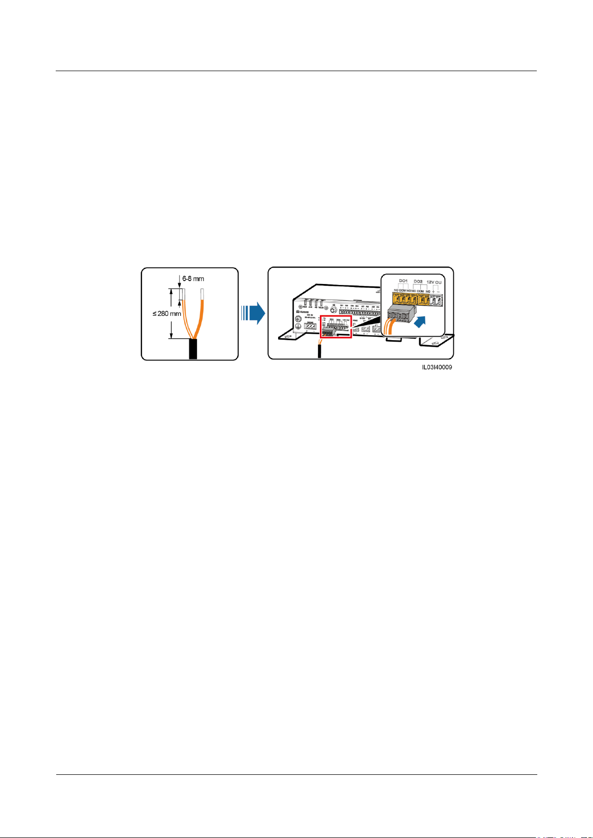
4.7 Connecting a DO Signal Cable
Context
The DO port supports a signal voltage of 12 V at most. NC and COM are normally closed
contacts, and NO and COM are normally open contacts. It is recommended that the signal
transmission distance be less than or equal to 10 m.
Procedure
Step 1 Connect a DO signal cable.
Figure 4-10 Connecting a DO signal cable
----End
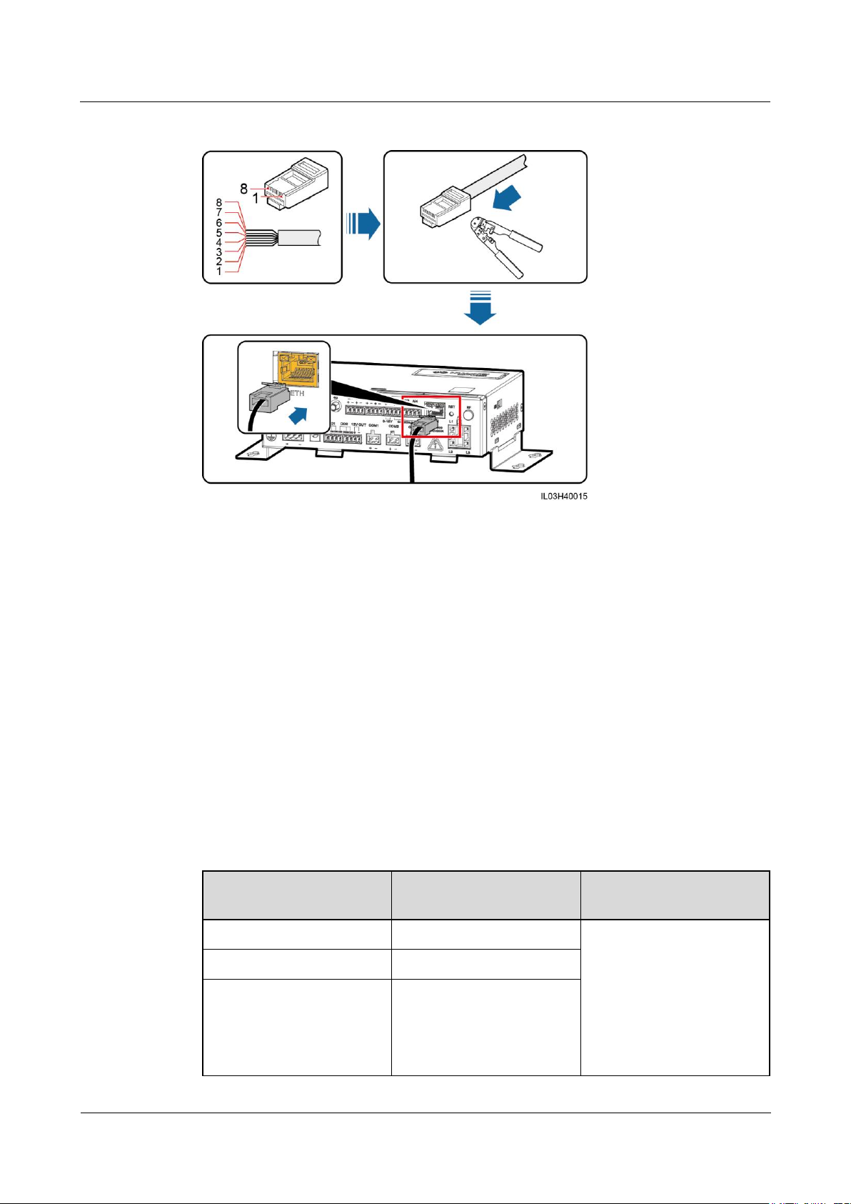
4.8 Connecting an Ethernet Cable
Context
The SmartLogger can connect to an Ethernet switch, router, or computer over an Ethernet
cable.
Procedure
Step 1 Connect an Ethernet cable.
Page 33
SmartLogger1000A
User Manual
4 Cable Connections
Issue 02 (2019-01-15)
Copyright © Huawei Technologies Co., Ltd.
26
Figure 4-11 Connecting an Ethernet cable
(1) White and orange
(2) Orange
(3) White and green
(4) Blue
(5) White and blue
(6) Green
(7) White and brown
(8) Brown
Number of Connected
Devices:
SIM Card Traffic
Traffic Baseline
1–5
Traffic ≤ 30 MB/month
Support updating device
performance data every 5
minutes.
Support the export of
inverter logs and I–V
diagnosis data, and the
inverter upgrading once
a month.
6–10
Traffic ≤ 50 MB/month
≥11
Traffic ≤ number of devices
x 5 MB/month
----End
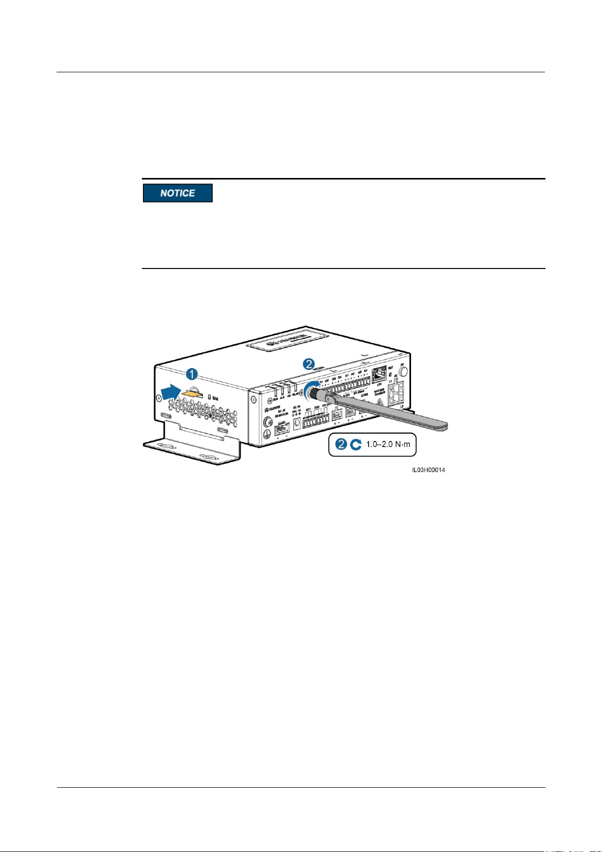
4.9 Installing a SIM Card and a 4G Antenna
Context
The SmartLogger provides the 4G wireless communication function. A SIM card of the local
carrier can be inserted for dial-up access.
Prepare a standard SIM card (dimension: 25 mm x 15 mm, capacity ≥ 64 KB)
Table 4-1 SIM card traffic description
Page 34
SmartLogger1000A
User Manual
4 Cable Connections
Issue 02 (2019-01-15)
Copyright © Huawei Technologies Co., Ltd.
27
Procedure
Step 1 Insert the SIM card into the SIM card slot.
Step 2 Install the antenna.
When installing the SIM card, determine its installation direction based on the silk screen
and arrow on the card slot.
Press the SIM card in place to lock it. The SIM card is correctly installed.
When removing the SIM card, push it inward to eject it.
Figure 4-12 Installing the SIM card and antenna
----End
Page 35
SmartLogger1000A
User Manual
5 System Operation
Issue 02 (2019-01-15)
Copyright © Huawei Technologies Co., Ltd.
28
5.1 Check Before Power-On
No.
Check That
1
The SmartLogger is installed correctly and securely.
2
All cables are connected securely.
3
Routing for the power cables and signal cables meets the requirements for
routing strong-current and weak-current cables and complies with the cable
routing plan.
4
Cables are bound neatly, and cable ties are secured evenly and properly in the
same direction.
5
There are no sundries such as unnecessary adhesive tape or cable ties on
cables.
Table 5-1 Items to be checked before power-on
5 System Operation
5.2 Powering On the System
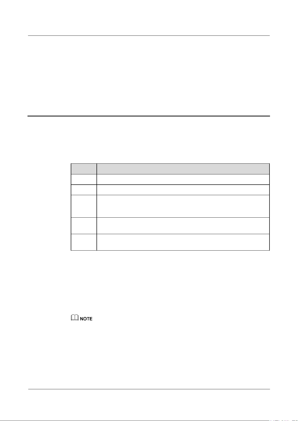
Step 1 Connect the input power cable.
Method 1: When a power adapter is used, connect the power adapter cable and turn on
the switch on the AC socket side.
The rated input of the power adapter is 100–240 V AC, 50/60 Hz.
Select an AC socket that matches the power adapter.
Page 36
SmartLogger1000A
User Manual
5 System Operation
Issue 02 (2019-01-15)
Copyright © Huawei Technologies Co., Ltd.
29
Figure 5-1 Supplying power through a power adapter
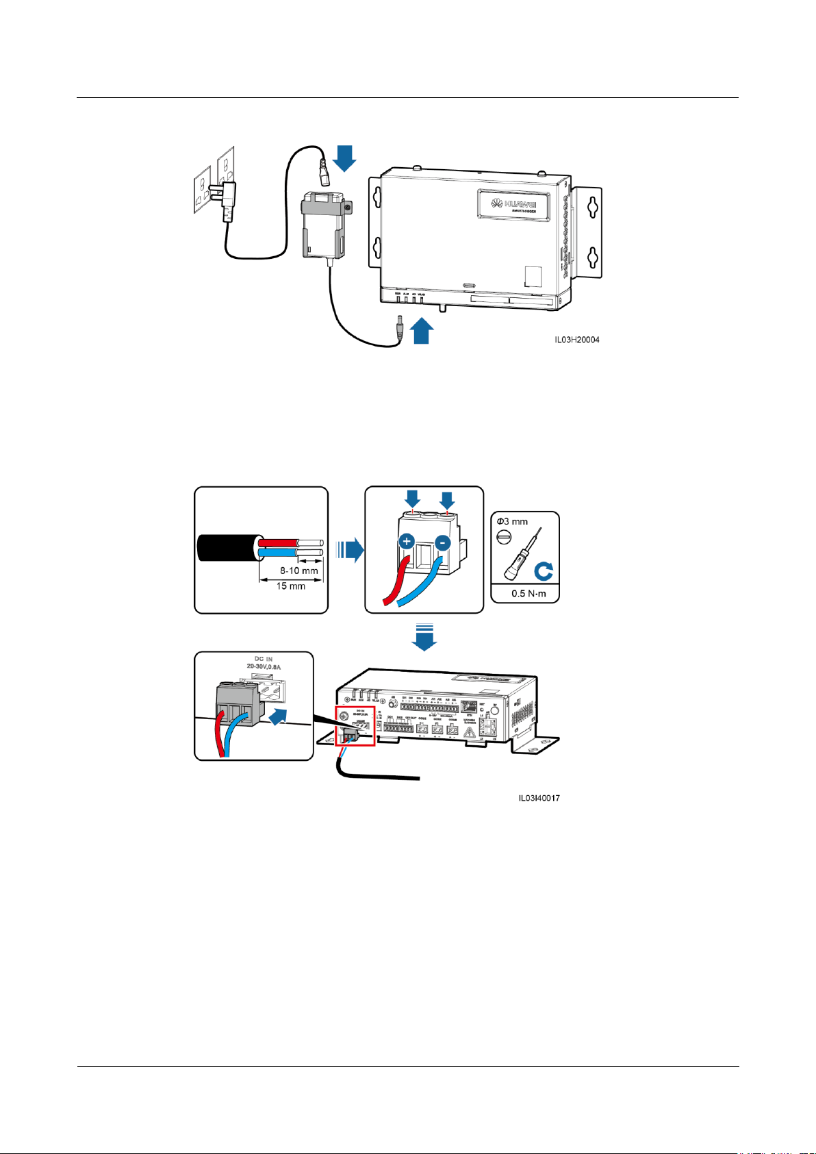
Method 2: When a DC power supply is used, connect the cable between the DC power
supply and the SmartLogger. Then, turn on the upstream power switch of the DC power
supply.
Figure 5-2 Supplying power through a DC power supply
Step 2 When PLC is used for communication, turn on all the upstream switch of the AC power cable
----End
Page 37
SmartLogger1000A
User Manual
6 WebUI Operations
Issue 02 (2019-01-15)
Copyright © Huawei Technologies Co., Ltd.
30
6.1 Introduction to WebUI
The web software version corresponding to the WebUI snapshots in this document is
SmartLogger V100R002C00SPC020. The snapshots are for reference only.
The parameter names, value ranges, and default values are subject to change. The actual
display prevails.
6 WebUI Operations
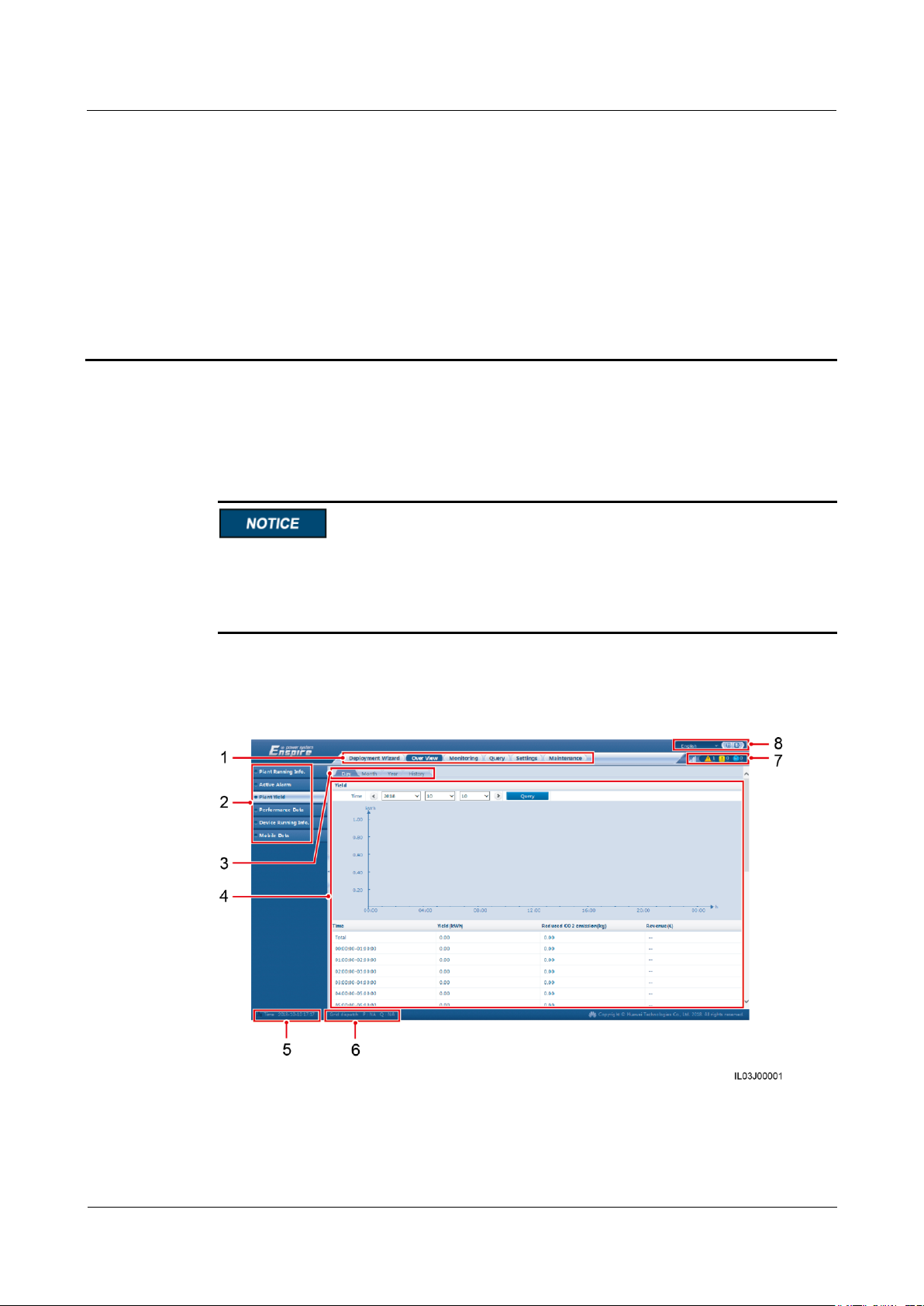
6.1.1 WebUI Layout
Figure 6-1 WebUI layout
Page 38
SmartLogger1000A
User Manual
6 WebUI Operations
Issue 02 (2019-01-15)
Copyright © Huawei Technologies Co., Ltd.
31
No.
Function
Description
1
Main menu
Click the corresponding main
menu before you perform an
operation over the WebUI.
2
Second-level menu
Under the main menu, choose the
device to be queried or the
parameter to be set under the
second-level menu.
3
Third-level menu
After selecting a second-level
menu, choose a third-level
menu to access the query or
setting page.
There is no third-level menu
under some second-level
menus.
4
Details page
Displays the details of the queried
information or parameter settings.
5
System time
Displays the current system time.
6
Power grid scheduling status
Displays the current power grid
scheduling mode of the system.
7
Alarm icon
Displays the severities and number
of active system alarms. You can
click a number to access the alarm
page.
8
Display language and logout
button
Allows you to select the display
language and log out.
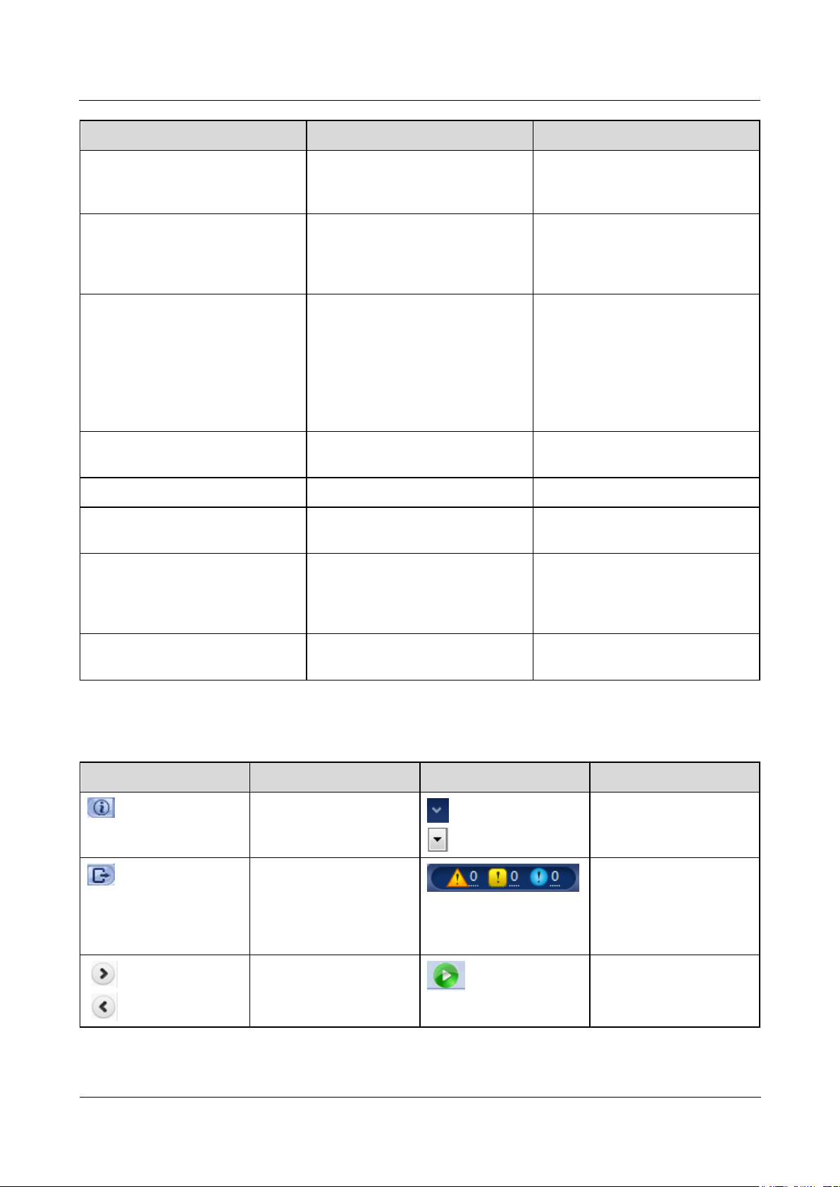
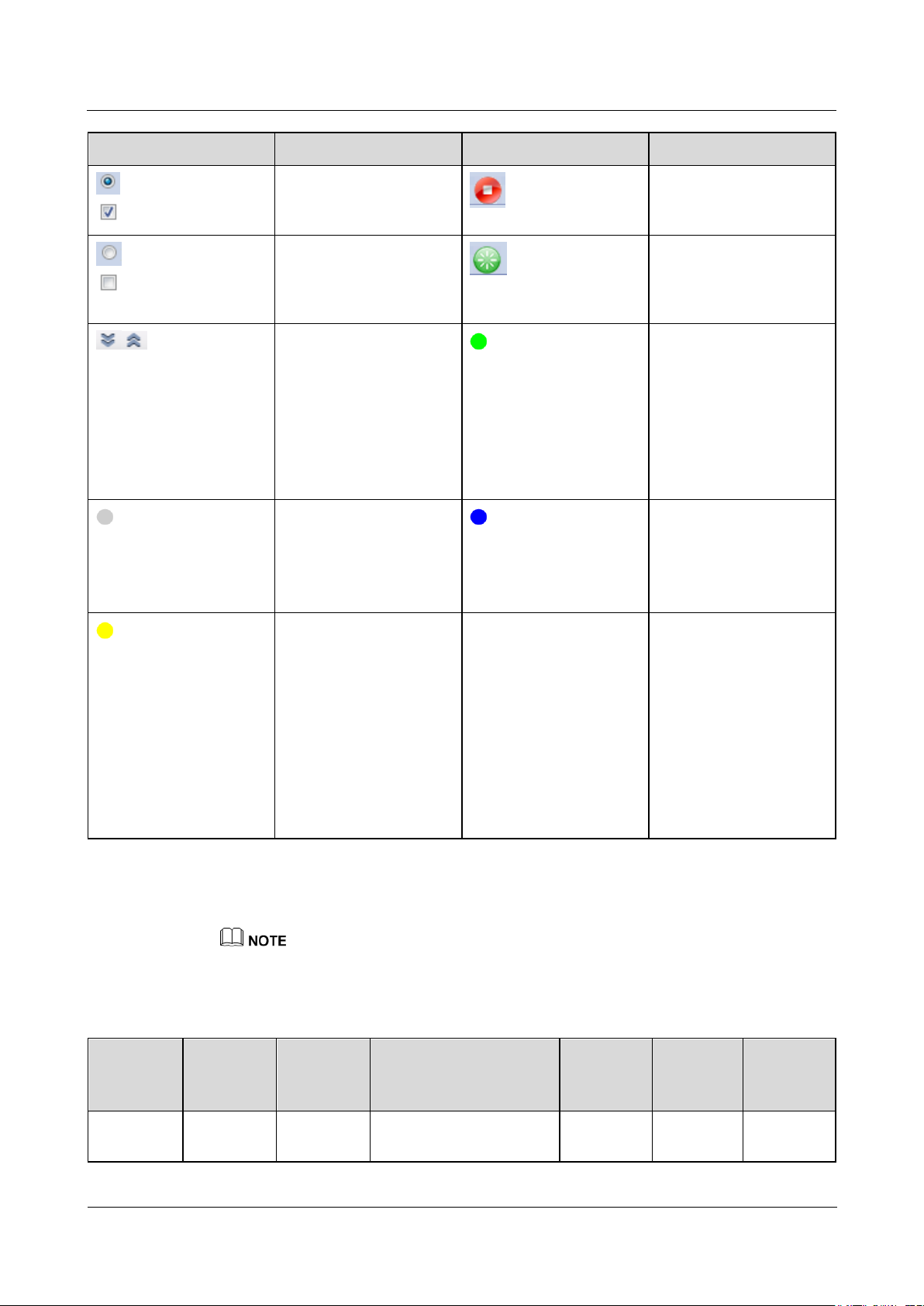
Icon
Description
Icon
Description
Click the About icon to
query the WebUI version
information.
Click the Drop-down
icon to select a parameter
or time.
Click the Exit icon to log
out.
Alarms are classified into
major, minor, and
warning ones. Click the
Alarm icon to query an
alarm.
Click the
Increase/Decrease icon to
adjust time.
Click the Start icon to
start the device.
6.1.2 Icon Description
Page 39
SmartLogger1000A
User Manual
6 WebUI Operations
Issue 02 (2019-01-15)
Copyright © Huawei Technologies Co., Ltd.
32
Icon
Description
Icon
Description
The Select icon indicates
that a parameter is
selected.
Click the Stop icon to
shut down the device.
The Select icon indicates
that a parameter is not
selected. Click the icon to
select a parameter.
Click the Reset icon to
reset the device.
Hide icon and Display
icon. Click them to hide
and expand parameters.
The inverter is in
On-grid state.
The EMI, power
meter, slave
SmartLogger, or PLC
is in Online state.
The PID is in
Running state.
The device is in
Disconnection state.
If a device is in
Disconnection state, its
parameters cannot be set.
The inverter is in
Loading state.
The inverter is in
Initializing,
Power-off, Idle, or
other state in which it
is not feeding power
into the grid.
The PID device is in
Power-off, Idle or
other state in which it
is not running
properly.
-
-
Main
Menu
Second-L
evel
Menu
Third-Lev
el Menu
Function
Common
User
Advance
d User
Special
User
Deploymen
t Wizard
-
-
Supports the deployment
wizard function. You can
○ ● ●
6.1.3 WebUI Menu
● indicates that the user has permission to operate the menu.
○ indicates that the user does not have permission to operate the menu.
Table 6-1 WebUI menus and user operation permissions
Page 40

SmartLogger1000A
User Manual
6 WebUI Operations
Issue 02 (2019-01-15)
Copyright © Huawei Technologies Co., Ltd.
33
Main
Menu
Second-L
evel
Menu
Third-Lev
el Menu
Function
Common
User
Advance
d User
Special
User
set deployment
parameters, connect
devices, and connect to
the management system
according to the wizard.
Over View
Plant
Running
Info.
-
Queries PV plant
information.
● ● ●
Active
Alarm
-
Queries active alarms.
● ● ●
Plant Yield
-
Queries the energy yield
of the system.
Daily energy yield:
The data can be stored
for 30 days on an
hourly basis.
Monthly energy yield:
The data can be stored
for one year on a daily
basis.
Annual energy yield:
The data can be stored
for 10 years on a
monthly basis.
Historical energy
yield: The data can be
stored for 25 years on
a yearly basis.
● ● ●
Performanc
e Data
-
Queries or exports
performance data.
● ● ●
Device
Running
Data
-
Queries or exports device
running information.
● ● ●
Mobile
Data
-
Queries mobile network
data.
● ● ●
Monitoring
SmartLogg
er1000A
Running
Info.
Queries the running
information.
● ● ●
Active
Alarm
Queries active alarms.
● ● ●
About
Queries the version and
communication
information of the master
SmartLogger.
● ● ●
Page 41

SmartLogger1000A
User Manual
6 WebUI Operations
Issue 02 (2019-01-15)
Copyright © Huawei Technologies Co., Ltd.
34
Main
Menu
Second-L
evel
Menu
Third-Lev
el Menu
Function
Common
User
Advance
d User
Special
User
SmartLogg
er
About
Queries the version and
communication
information of the slave
SmartLogger.
● ● ●
SUN2000
Running
Info.
Queries the running
information.
● ● ●
Active
Alarm
Queries active alarms.
● ● ●
Performanc
e Data
Queries or exports
performance data.
● ● ●
Yield
Queries the energy yield.
● ● ●
Running
Param.
Sets running parameters.
○ ● ●
Tracking
System
Sets tracing system
parameters.
○ ● ○
LVRT
Characteris
tic Curve
Sets the curve of the
LVRT feature.
○ ○ ●
About
Queries the version and
communication
information.
● ● ●
PLC
Running
Info.
Queries the running
information.
● ● ●
STA List
Sets or synchronizes
the baud rates of PLC
communication
devices.
Exports the STA list.
○ ● ○
Networkin
g Settings
Sets running
parameters.
Manages the SN list.
○ ● ○
About
Queries the version and
communication
information.
● ● ●
EMI
Running
Info.
Queries the running
information.
● ● ●
Performanc
e Data
Queries or exports
performance data.
● ● ●
Running
Sets running parameters.
○ ● ○
Page 42

SmartLogger1000A
User Manual
6 WebUI Operations
Issue 02 (2019-01-15)
Copyright © Huawei Technologies Co., Ltd.
35
Main
Menu
Second-L
evel
Menu
Third-Lev
el Menu
Function
Common
User
Advance
d User
Special
User
Param.
About
Queries the version and
communication
information.
● ● ●
Power
Meter
Running
Info.
Queries the running
information.
● ● ●
Performanc
e Data
Queries or exports
performance data.
● ● ●
Running
Param.
Sets the running
parameters of the
DL/T645 power meter.
○ ● ●
About
Queries the version and
communication
information.
● ● ●
PID
Running
Info.
Queries the running
information.
● ● ●
Active
Alarm
Queries active alarms.
● ● ●
Performanc
e Data
Queries or exports
performance data.
● ● ●
Running
Param.
Sets running parameters.
○ ● ○
About
Queries the version and
communication
information.
● ● ●
Custom
Device and
IEC103
Device
Running
Info.
Queries the running
information.
● ● ●
Teleindicat
ion
Queries teleindication
parameters.
● ● ●
Telemeteri
ng
Queries telemetering
parameters.
● ● ●
Telecontrol
Sets telecontrol
parameters.
● ● ●
Teleadjust
Sets teleadjust
parameters.
● ● ●
Query
Alarm
History
-
Queries historical alarms.
● ● ●
Operation
Log
-
Queries operation logs.
○ ● ●
Page 43

SmartLogger1000A
User Manual
6 WebUI Operations
Issue 02 (2019-01-15)
Copyright © Huawei Technologies Co., Ltd.
36
Main
Menu
Second-L
evel
Menu
Third-Lev
el Menu
Function
Common
User
Advance
d User
Special
User
Export
Data
-
Exports historical alarms,
energy yield, operation
logs, and power grid
scheduling data.
○ ● ●
Settings
User
Param.
Date&Tim
e
Sets the date and time.
● ● ○
Plant
Sets PV plant
information.
● ● ○
Revenue
Sets the revenue
parameters.
● ● ○
Save
Period
Sets the save period of
performance data.
● ● ○
Comm.
Param.
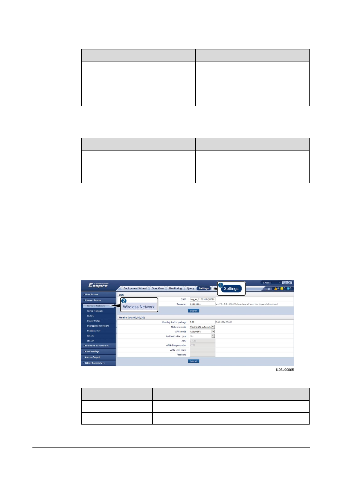
Wireless
Network
Changes the SSID and
password of the
built-in WLAN.
Sets mobile data
(4G/3G/2G)
parameters.
○ ● ○
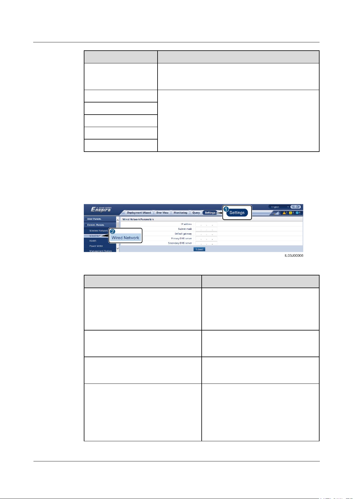
Wired
Network
Sets wired network
parameters.
○ ● ○
RS485
Sets RS485 parameters.
○ ● ●
Power
Meter
Sets power meter
parameters.
○ ● ●
Manageme
nt
Sets management
system parameters.
Uploads the security
certificate.
○ ● ○
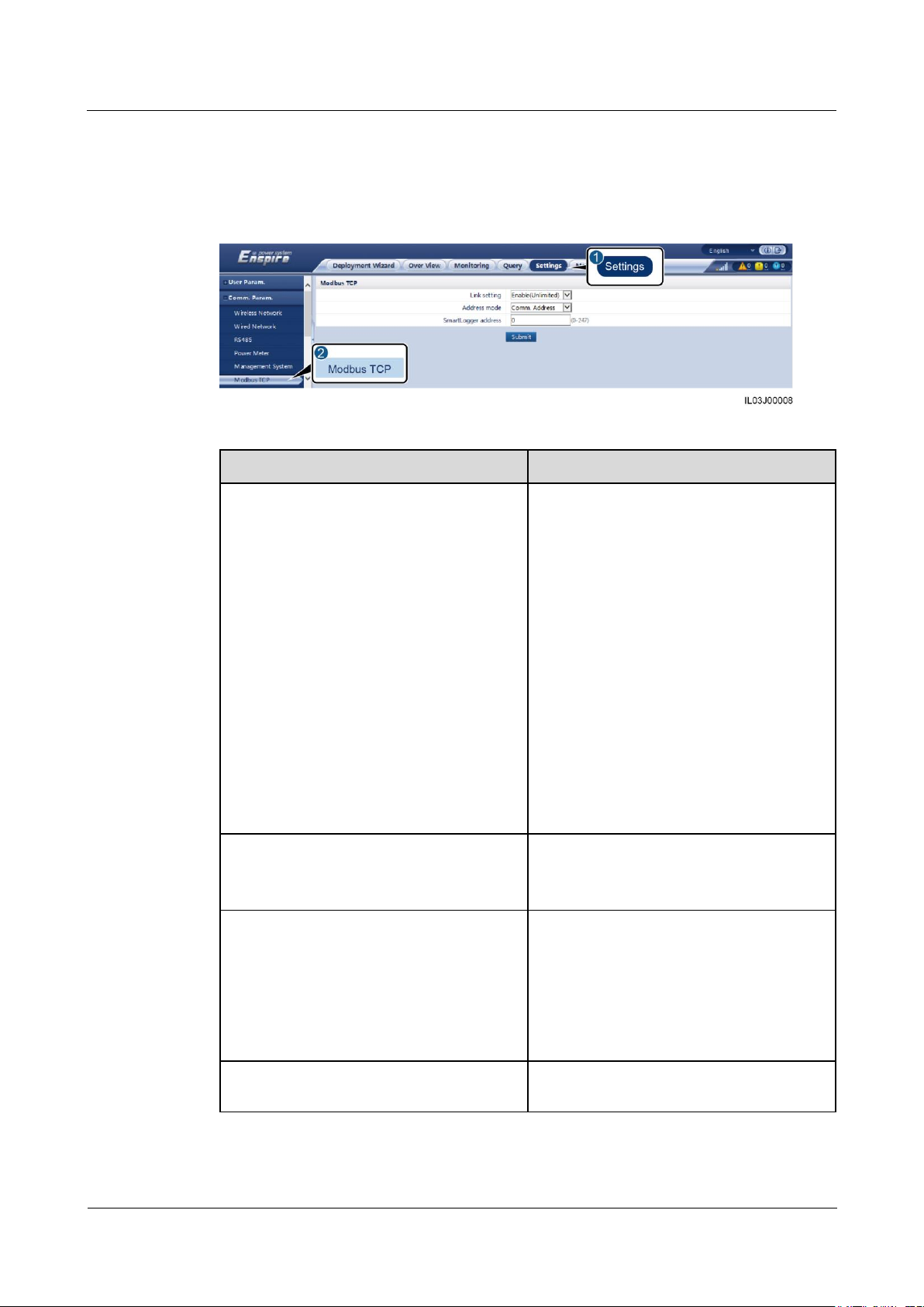
Modbus
TCP
Sets Modbus TCP
parameters.
○ ● ●
IEC103
Sets IEC103 parameters.
○ ● ○
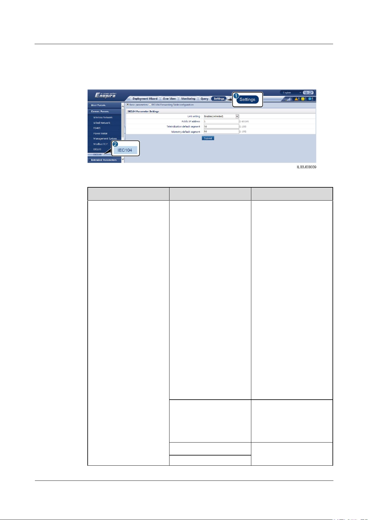
IEC104
Sets IEC104 parameters.
○ ● ○
Extended
Parameters
FTP
Sets FTP parameters.
○ ● ○
Email
Sets email parameters.
○ ● ○
Port
Setting
DO
Configures the DO port
function.
○ ● ○
USB
Configures the USB port
function.
○ ● ○
Alarm
-
Sets the association
○ ● ○
Page 44

SmartLogger1000A
User Manual
6 WebUI Operations
Issue 02 (2019-01-15)
Copyright © Huawei Technologies Co., Ltd.
37
Main
Menu
Second-L
evel
Menu
Third-Lev
el Menu
Function
Common
User
Advance
d User
Special
User
Output
between the inverter
alarms and DO port.
Other
Parameters
-
Sets RS485 upgrade
rate autonegotiation.
Sets AI1 SPD
detection alarm.
○ ● ○
Active
Power
Control
-
Sets parameters for active
power control.
○ ○ ●
Reactive
Power
Control
-
Set parameters for
reactive power control.
○ ○ ●
Dry
Contact
Remote
Shut
-
Sets parameters for
remote shutdown over dry
contacts.
○ ○ ●
DI
-
Configures the DI port
function.
○ ○ ●
Export
Limitation
-
Sets export limitation
parameters.
○ ○ ●
DRM
-
Sets the DRM parameters.
○ ○ ●
Maintenanc
e
Firmware
Upgrade
-
Upgrades the firmware of
the SmartLogger,
inverter, PLC module, or
PID module.
○ ● ●
Product
Informatio
n
-
Queries product
information.
● ● ●
Security
Settings
-
Changes the user
password.
Sets the automatic
logout time.
Uploads a network
security certificate.
Updates the key.
Sets web TLS1.0.
An advanced user or a
special user can
configure digital
signature verification.
● ● ●
System
- Resets the system.
○ ● ●
Page 45

SmartLogger1000A
User Manual
6 WebUI Operations
Issue 02 (2019-01-15)
Copyright © Huawei Technologies Co., Ltd.
38
Main
Menu
Second-L
evel
Menu
Third-Lev
el Menu
Function
Common
User
Advance
d User
Special
User
Maint. Restores the factory
settings.
Clears data.
Full profile export.
Full profile import.
Device Log
-
Exports device logs.
○ ● ●
Onsite Test
Inspection
Starts the inverter health
check.
○ ● ●
Spot-check
Starts the inverter
spot-check.
○ ● ●
License
Manageme
nt
-
Views the license
information.
Exports the license
application file.
Loads or revokes a
license.
○ ● ●
Device
Mgmt.
Connect
Device
Adds or removes a
device.
Imports or exports
configurations.
○ ● ●
Device List
Modifies device
information.
Imports or exports
device information.
○ ● ●
Export
Param.
Exports device
parameters.
○ ● ●
Clear
Alarm
Clears device alarms.
○ ● ●
Collect
Perf. Data
Recollects historical
performance data and
energy yield of devices.
○ ● ●
Adjust total
energy
yield
Calibrates the
accumulated energy yield.
○ ● ●
The third-level menu varies with the device model and grid code. The displayed menu prevails.
Page 46

SmartLogger1000A
User Manual
6 WebUI Operations
Issue 02 (2019-01-15)
Copyright © Huawei Technologies Co., Ltd.
39
6.2 Device Commissioning
Item
SmartLogger Default
Value
Example PC Setting
IP address
192.168.0.10
192.168.0.11
Subnet mask
255.255.255.0
255.255.255.0
Default gateway
192.168.0.1
192.168.0.1
Prerequisites
Device and cable installation has been checked according to PV plant specifications and
requirements.
The PV plant devices and SmartLogger are powered on.
You have obtained the IP address of the SmartLogger as well as the user name and
password used for logging in to the WebUI.
Context
After installing or replacing a device or SmartLogger, you need to set device parameters and
add the device.
6.2.1 Preparations and WebUI Login
Prerequisites
Operating system: Windows 7 or later
Browser: Chrome52, Firefox58, Internet Explorer 9 or later is recommended.
Procedure
Step 1 Connect the network cable between the network port on the PC and the ETH port on the
Step 2 Set the IP addresses of the PC and SmartLogger in the same network segment.
Step 3 Set LAN parameters.
SmartLogger.
If the SmartLogger is connected to a local area network (LAN) and a proxy server has
been set, you need to cancel the proxy server settings.
If the SmartLogger is connected to the Internet and the PC is connected to the LAN, do not
cancel the proxy server settings.
1. Open Internet Explorer.
2. Choose Tools > Internet Options.
3. Click the Connections tab and then click LAN settings.
Page 47

SmartLogger1000A
User Manual
6 WebUI Operations
Issue 02 (2019-01-15)
Copyright © Huawei Technologies Co., Ltd.
40
4. Clear Use a proxy server for your LAN.
Figure 6-2 LAN settings
5. Click OK.
Step 4 Log in to the SmartLogger WebUI.
1. Enter https://XX.XX.XX.XX (XX.XX.XX.XX is the IP address of the SmartLogger) in
the address box of the browser, and press Enter. The login page is displayed.
If you log in to the WebUI for the first time, a security risk warning is displayed. Click
Continue to the website (not recommended) to log in to the WebUI.
It is recommended that users use their own certificates. If the certificate is not replaced, the security
risk warning will be displayed during each login.
After logging in to the WebUI, you can import a certificate under Maintenance > Security
Settings > Network Security Certificate.
The imported security certificate needs to be bound to the SmartLogger IP address. Otherwise, the
security risk warning will still be displayed during login.
Figure 6-3 Security risk warning
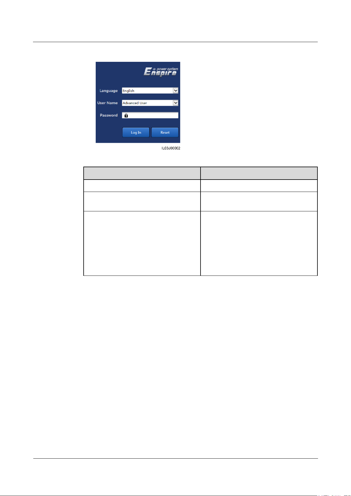
2. Specify Language, User Name, and Password, and click Log In.
Page 48
SmartLogger1000A
User Manual
6 WebUI Operations
Issue 02 (2019-01-15)
Copyright © Huawei Technologies Co., Ltd.
41
Figure 6-4 Login page
Parameter
Description
Language
Set this parameter as required.
User Name
If device commissioning is required, select
Advanced User or Special User.
Password
The initial password is Changeme.
Change the password immediately to
ensure account security.
If you enter incorrect passwords for five
consecutive times within 5 minutes, your
account will be locked out. You need to
try again with the account 10 minutes
later.
----End
Follow-up Procedure
If any page is blank or a menu cannot be accessed after you log in to the WebUI, clear the
cache, refresh the page, or log in again.
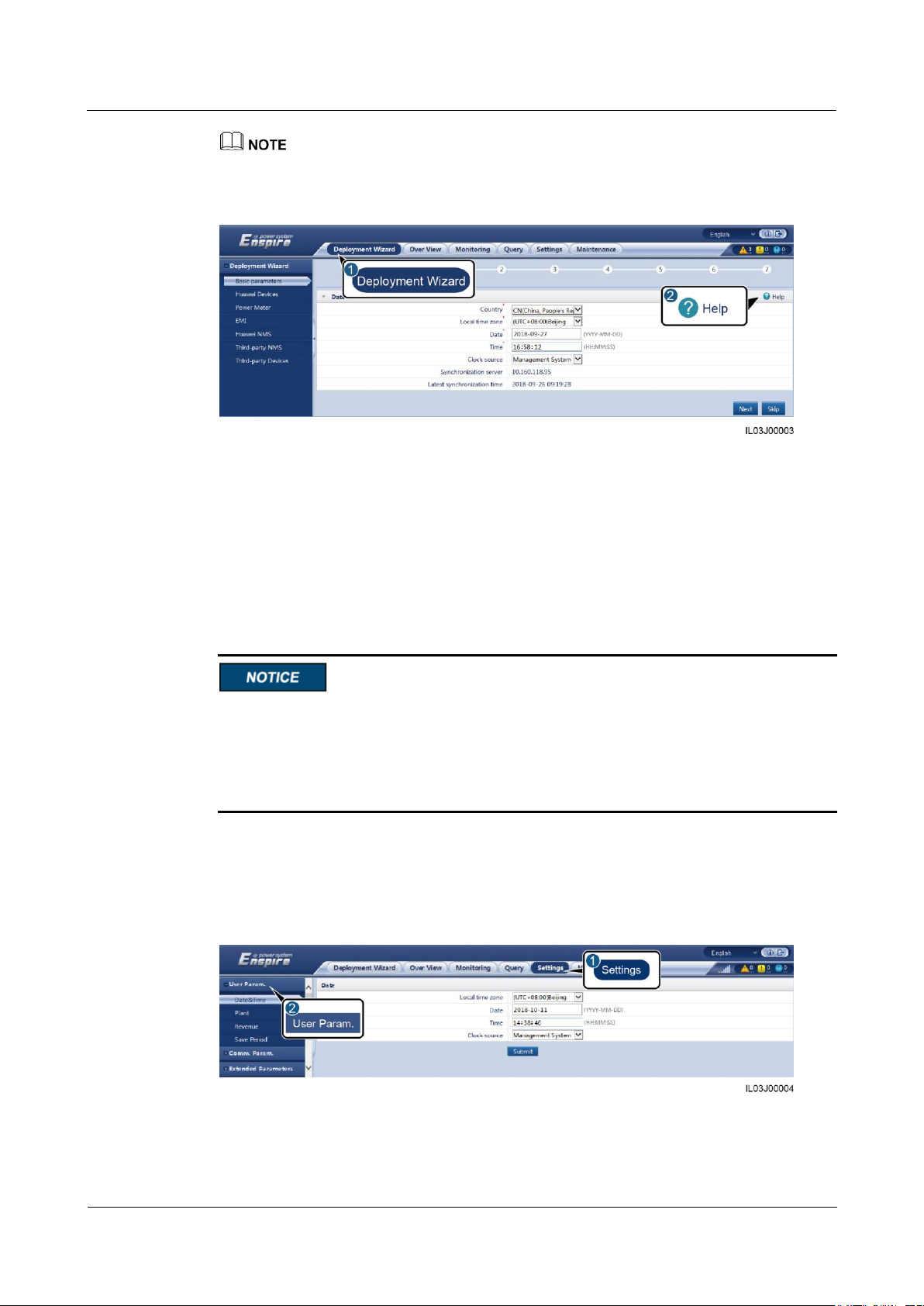
6.2.2 Performing Deployment Wizard
Context
The deployment wizard allows you to configure basic SmartLogger parameters, connect
Huawei devices, power meters, and EMIs, configure Huawei NMS, and implement
interworking with third-party devices.
Procedure
Step 1 Log in as Advanced User or Special User to access the deployment wizard page.
Step 2 Set parameters as prompted. For details, click Help on the page.
Page 49
SmartLogger1000A
User Manual
6 WebUI Operations
Issue 02 (2019-01-15)
Copyright © Huawei Technologies Co., Ltd.
42
When setting parameters, click Previous, Next, and Skip as required.
Figure 6-5 Deployment wizard
Step 3 After setting parameters, click Finish.
----End
6.3 Parameter Settings
If the parameters listed in this section have been set in Deployment Wizard, ignore the
settings for these parameters.
If the PV plant does not contain certain devices, such as electricity meters, EMIs, IEC103
devices, and custom devices, ignore the corresponding settings.
You are advised to log in as Advanced User and set related parameters.
6.3.1 Setting User Parameters
Log in as Common User or Advanced User, set user parameters, and click Summit.
Figure 6-6 Setting user parameters
Page 50
SmartLogger1000A
User Manual
6 WebUI Operations
Issue 02 (2019-01-15)
Copyright © Huawei Technologies Co., Ltd.
43
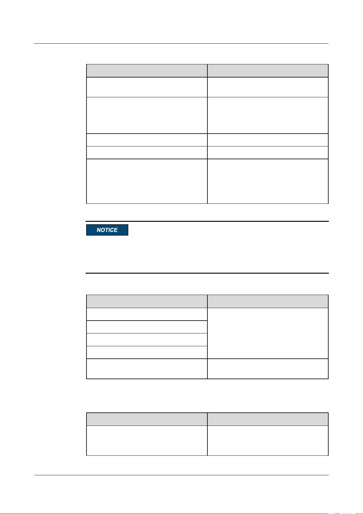
Date&Time
Parameter
Description
Local time zone
Select a time zone based on the region
where the PV plant is located.
DST enable
Set this parameter as required.
NOTE
This parameter is unavailable for zones without
DST.
Date
Set this parameter to the local date.
Time
Set this parameter to the local time.
Clock source
Set this parameter as required.
The value can be NTP, Management
System, IEC104, or Modbus-TCP. If there
is no management system, ignore the
corresponding setting.
Parameter
Description
Plant name
Set this parameter as required.
NOTE
In the English half-width status, you cannot enter
any of the following characters:
<>:,`'?()#&\$|%+;~^"
Plant address
Plant owner
Plant owner address
Country
Select a country based on the region where
the PV plant is located.
Parameter
Description
Currency
Set this parameter as required.
The value can be EUR, GBP, USD, CNY,
or JPY.
Plant
Revenue
After the date and time are set, the date and time of all the inverters connected to the
SmartLogger are updated accordingly. Ensure that the settings are correct.
Changing the date and time affects the recording of system energy yield and performance
data. Do not change the time zone or system time unless necessary.
Page 51
SmartLogger1000A
User Manual
6 WebUI Operations
Issue 02 (2019-01-15)
Copyright © Huawei Technologies Co., Ltd.
44
Parameter
Description
Electricity price/kWh
Set this parameter to the local electricity
price, which is used to calculate the
converted revenue of the energy yield.
CO2 emission reduction coefficient
Set this parameter based on the local
standard.
Parameter
Description
Performance data save period
Set this parameter to the save period of
performance data. After the setting, the data
will be displayed accordingly on the
performance data page.
Parameter
Description
Monthly traffic package
Set this parameter based on the SIM card traffic package.
Network mode
Set this parameter based on the SIM card network mode.
Save Period
6.3.2 Setting Parameters for Connecting to the NMS
Procedure
Step 1 Log in as Advanced User and set up a network connection.
Method 1: If the SmartLogger connects to the NMS over the 4G/3G/2G network, set
mobile data parameters and click Submit.
Figure 6-7 Setting mobile data parameters
Page 52
SmartLogger1000A
User Manual
6 WebUI Operations
Issue 02 (2019-01-15)
Copyright © Huawei Technologies Co., Ltd.
45
Parameter
Description
APN mode
The default value is Automatic. Set this parameter to
Manual if the dial-up connection cannot be set up in
Automatic mode.
Authentication type
When APN mode is set to Manual, you need to set the
parameters related to the SIM card. Obtain the information
about the parameters from the SIM card operator.
APN
APN dialup number
APN user name
Password
Parameter
Description
IP Address
Set this parameter based on the PV plant
plan.
NOTE
If the IP address is changed, use the new IP
address to log in again.
Subnet mask
Set this parameter based on the actual
subnet mask of the LAN where the
SmartLogger is located.
Default gateway
Set this parameter based on the actual
gateway of the LAN where the
SmartLogger is located.
Primary DNS server
You can ignore this parameter if the
SmartLogger connects to the LAN.
Set this parameter to the IP address of the
LAN router when the SmartLogger connects
to the public network (for example,
connecting to the hosting cloud server,
email server, or third-party FTP server).
Method 2: If the SmartLogger connects to the NMS over a wired network, set the wired
network parameters and click Submit.
Figure 6-8 Setting wired network parameters
Page 53

SmartLogger1000A
User Manual
6 WebUI Operations
Issue 02 (2019-01-15)
Copyright © Huawei Technologies Co., Ltd.
46
Parameter
Description
Secondary DNS server
In normal cases, you can ignore this
parameter.
If the primary DNS server cannot resolve
the domain name, the secondary DNS server
is used.
Parameter
Description
Server
Set this parameter to the IP address or domain name of the
management system.
Port
Set this parameter based on the connected management
system.
Address mode
The value can be Comm.address or Logical address.
If the communication address of the device connected to the
SmartLogger is unique, you are advised to select
Comm.address. In other cases, you must select Logical
address.
SSL encryption
Retain the default value Enable.
NOTE
If this parameter is set to Disable, data exchange between the
SmartLogger and the management system will not be encrypted,
which poses security risks.
Second challenge
authentication
If this parameter is set to Disable, the system does not check
the result of the second challenge authentication.
Security certificate
Optional. Set this parameter only when the certificate has
expired or the customer needs to use their own certificate.
Step 2 Set the management system parameters.
Method 1: If the SmartLogger connects to a Huawei NMS or a third-party NMS using
the encrypted Modbus TCP protocol, log in as Advanced User, set management system
parameters, and click Submit.
Figure 6-9 Setting management system parameters
Page 54
SmartLogger1000A
User Manual
6 WebUI Operations
Issue 02 (2019-01-15)
Copyright © Huawei Technologies Co., Ltd.
47
Parameter
Description
Link setting
Modbus TCP is a general standard protocol
without a security authentication
mechanism. To reduce network security
risks, the function of connecting to a
third-party NMS using the Modbus TCP
protocol is disabled by default.
To use this function, you can set this
parameter to Enable(Limited) or
Enable(Unlimited).
If this parameter is set to
Enable(Limited), the SmartLogger can
connect to a maximum of five preset
third-party NMSs.
If this parameter is set to
Enable(Unlimited), the SmartLogger
can connect to any third-party NMS with
a valid IP address.
Client N IP Address
NOTE
N is 1, 2, 3, 4, or 5.
If Link setting is set to Enable(Limited),
set this parameter based on the IP address of
the third-party NMS.
Address mode
The value can be Comm.address or
Logical address.
If the communication address of the device
connected to the SmartLogger is unique,
you are advised to select Comm.address. In
other cases, you must select Logical
address.
SmartLogger address
Set this parameter to the communication
address of the SmartLogger.
Method 2: If the SmartLogger connects to a third-party NMS using the unencrypted
Modbus-TCP protocol, log in as Advanced User or Special User, set Modbus TCP
parameters, and click Submit.
Figure 6-10 Setting Modbus TCP parameters
Page 55
SmartLogger1000A
User Manual
6 WebUI Operations
Issue 02 (2019-01-15)
Copyright © Huawei Technologies Co., Ltd.
48
Tab
Parameter
Description
Basic parameters
Link setting
IEC104 is a general standard
protocol without a security
authentication mechanism.
To reduce network security
risks, the function of
connecting to a third-party
NMS using the IEC104
protocol is disabled by
default.
To use this function, set this
parameter to
Enable(Limited) or
Enable(Unlimited).
If this parameter is set to
Enable(Limited), the
SmartLogger can
connect to a maximum
of five preset third-party
NMSs.
If this parameter is set to
Enable(Unlimited), the
SmartLogger can
connect to any
third-party NMS with a
valid IP address.
IEC104-N IP
NOTE
N is 1, 2, 3, 4, or 5.
If Link setting is set to
Enable(Limited), set this
parameter based on the IP
address of the third-party
NMS.
Public IP address
Set these parameters as
required.
Teleindication default
Method 3: If the SmartLogger connects to a third-party NMS using the IEC104 protocol,
log in as Advanced User, set IEC104 parameters, and click Submit.
Figure 6-11 Setting IEC104 parameters
Page 56
SmartLogger1000A
User Manual
6 WebUI Operations
Issue 02 (2019-01-15)
Copyright © Huawei Technologies Co., Ltd.
49
Tab
Parameter
Description
segment
Telemetry default segment
IEC104 forwarding table
configuration
-
Set this parameter as
required.
NOTE
After the IEC104
configuration file exported
from the SmartLogger and the
device type IEC104
information files delivered
with devices are correctly
configured in a third-party
NMS, the third-party NMS
will be able to monitor devices
connected to the SmartLogger
over the IEC104 protocol.
Parameter
Description
Protocol
Set this parameter based on the protocol
type of the connected device.
The value can be Modbus, IEC103,
DL/T645, Modbus-Slave, or
Modbus-Control.
----End
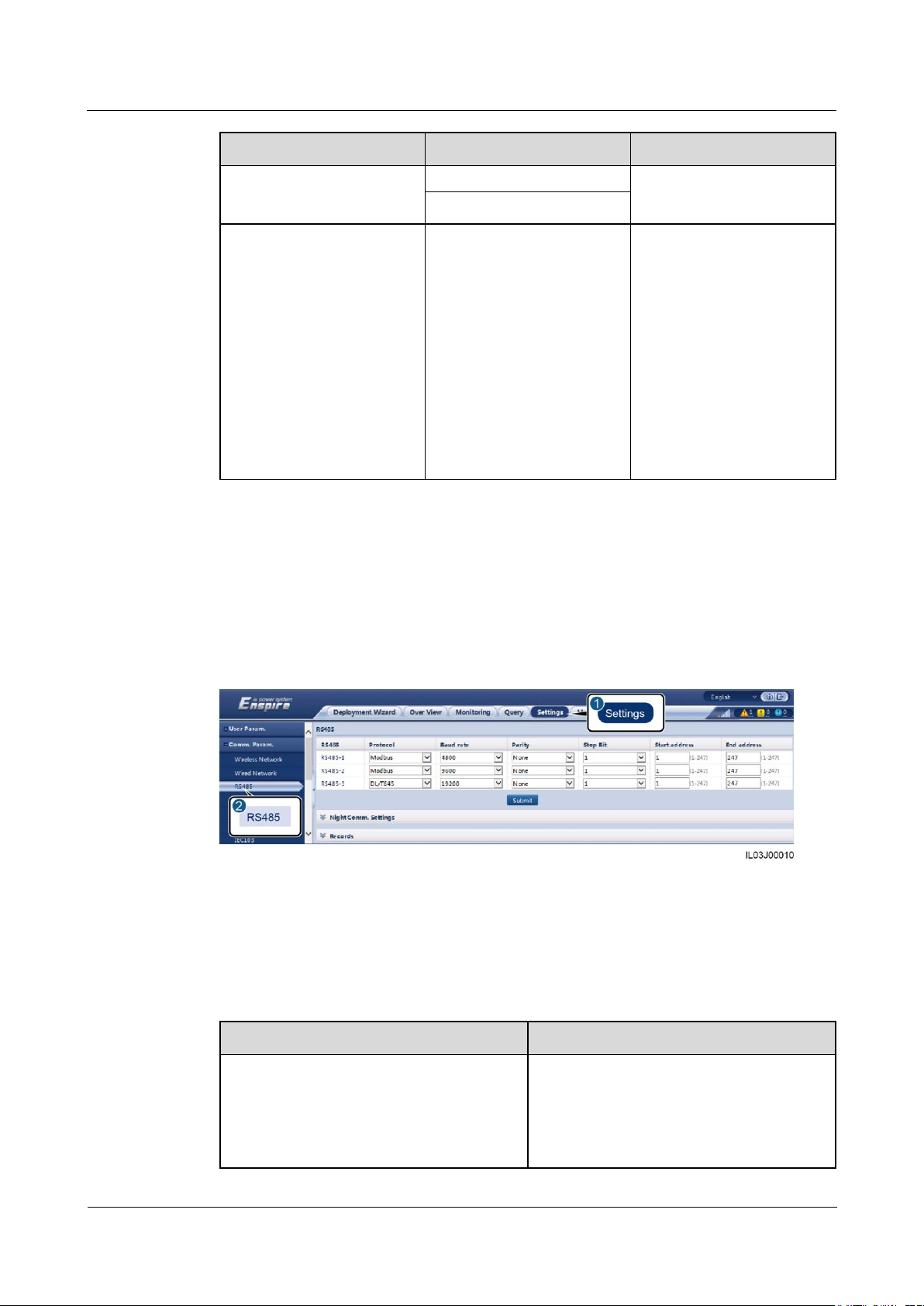
6.3.3 Setting RS485 Communications Parameters
Log in as Advanced User or Special User, set RS485 parameters, and click Submit.
Figure 6-12 Setting RS485 parameters
RS485
RS485-1 to RS485-3 correspond to communications ports COM1 to COM3 respectively.
Protocol, Baud rate, Parity, and Stop Bit must be set to the same values for the devices
connected to the same COM port.
Page 57
SmartLogger1000A
User Manual
6 WebUI Operations
Issue 02 (2019-01-15)
Copyright © Huawei Technologies Co., Ltd.
50
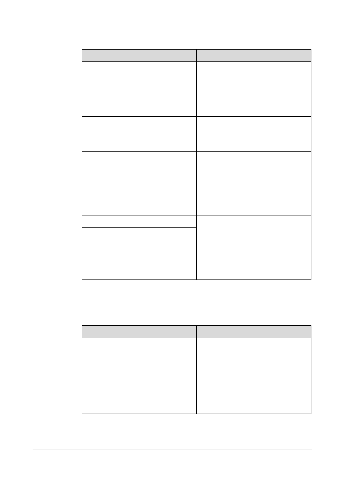
Parameter
Description
NOTE
When the SmartLogger serves as a slave
node to interconnect with a third-party device
over Modbus-RTU, set Protocol to
Modbus-Slave.
When the connected inverter performs rapid
power grid scheduling using both PLC and
RS485, set Protocol to Modbus-Control.
Baud rate
Set this parameter based on the baud rate of
the connected device.
The value can be 2400, 4800, 9600, 19200,
or 115200.
Parity
Set this parameter based on the parity mode
of the connected device.
The value can be None, Odd parity, or
Even parity.
Stop Bit
Set this parameter based on the stop bit of
the connected device.
The value can be 1 or 2.
Start address
1 ≤ Start address ≤ Communication address
of the connected device ≤ End address ≤
247
The address segments for RS485-1 to
RS485-3 can overlap.
NOTE
The start and end addresses have no impact on
the devices that have been connected.
End address
Parameter
Description
Night silent
Specifies whether the night silent mode is
enabled.
Enter time
Specifies the time for entering the night
silent mode.
Exit time
Specifies the time for exiting the night silent
mode.
Wakeup period
Specifies the wakeup period for the night
silent mode.
Night Comm. Settings
If device information query is not required at night, enable Night silent.
Page 58

SmartLogger1000A
User Manual
6 WebUI Operations
Issue 02 (2019-01-15)
Copyright © Huawei Technologies Co., Ltd.
51
Records
Parameter
Description
Choose port
Specifies the port for recording packets.
The value can be All, PLC, RS485-1,
RS485-2, or RS485-3.
Parameter
Description
Device Type
Set this parameter to SmartLogger.
IP address
Set this parameter to the IP address of the
slave SmartLogger.
The SmartLogger supports exporting of PLC and RS485 communication packets.
Set Choose port and click Start to start packet recording. Then, click Export to stop packet
recording and export the packets.
6.3.4 Setting Slave SmartLogger Parameters
Log in as Advanced User or Special User, set the access parameters for the slave
SmartLogger, and click Add Devices.
The communications parameter Modbus TCP must be set to Enable(Umlimited).
Figure 6-13 Setting access parameters
6.3.5 Setting PLC CCO Parameters
Procedure
Step 1 Log in as Advanced User or Special User and set access parameters.
Page 59

SmartLogger1000A
User Manual
6 WebUI Operations
Issue 02 (2019-01-15)
Copyright © Huawei Technologies Co., Ltd.
52
Parameter
Description
Built-in PLC
If the SmartLogger communicates with
the inverter using a built-in PLC, set this
parameter to Enable.
If only RS485 communication is used
between the SmartLogger and the
inverter and third-party device, set this
parameter to Disable.
Device disconnection time
Specifies the duration for determining
device disconnection.
Set parameters for the built-in PLC CCO and click Submit.
Figure 6-14 Setting parameters for the built-in PLC
Set access parameters for an external PLC CCO.
− Method 1: Click Auto. Search to connect to the PLC CCO.
− Method 2: Click Add Devices, set access parameters, and click Add Devices.
Page 60

SmartLogger1000A
User Manual
6 WebUI Operations
Issue 02 (2019-01-15)
Copyright © Huawei Technologies Co., Ltd.
53
Figure 6-15 Setting access parameters for an external PLC
Parameter
Description
Device type
Set this parameter to PLC.
Port number
Set this parameter to the number of the
COM port connected to the PLC CCO.
Category
Parameter
Description
Running Param.
Baud rate
Retain the default value
115200 for optimal
communications
performance.
Anti-crosstalk
Set this parameter to
Enable. When the box-type
transformer number and
winding number of the
inverter are the same as
those of the PLC CCO, or
the inverter SN is in the SN
Step 2 Log in as Advanced User and set networking parameters.
Figure 6-16 Networking settings
Page 61

SmartLogger1000A
User Manual
6 WebUI Operations
Issue 02 (2019-01-15)
Copyright © Huawei Technologies Co., Ltd.
54
Category
Parameter
Description
list, the inverter can connect
to the SmartLogger over a
PLC network.
Network frequency band
U.S.: Set this parameter
to 1.7–4.9 (MHz).
Other regions: Retain the
default value 2.5–5.7
(MHz).
NOTE
Other network frequency
bands are reserved.
Box-type transformer No.
Set this parameter based on
the number of the box-type
transformer connected to the
SmartLogger.
Winding No.
In multi-split box-type
transformer scenarios, set
this parameter based on the
number of the winding of
the box-type transformer
connected to the
SmartLogger.
Networking
When the SmartLogger
communicates with the
inverter over PLC, set
Networking to Enable.
When the SmartLogger
communicates with the
inverter only over
RS485, set Networking
to Disable.
SN List
-
Maintain the inverter SN
list.
You can click
Synchronize to
synchronize the box-type
transformer number and
winding number of the
PLC CCO to the
inverters in the SN list.
----End
Page 62

SmartLogger1000A
User Manual
6 WebUI Operations
Issue 02 (2019-01-15)
Copyright © Huawei Technologies Co., Ltd.
55
6.3.6 Setting SUN2000 Parameters
Parameter
Description
Device type
Set this parameter to SUN2000.
Connection mode
If the inverter uses PLC for
communication, set this parameter to
PLC.
If the inverter uses RS485 for
communication, set this parameter to the
COM port connected to the inverter.
Address
Set this parameter to the communication
address of the inverter.
Procedure
Step 1 Log in as Advanced User or Special User and set access parameters.
Method 1: Click Auto. Search to connect to the SUN2000.
Method 2: Click Add Devices, set access parameters, and click Add Devices.
Figure 6-17 Setting access parameters
Step 2 Set running parameters and click Submit.
Before setting the running parameters of the inverter, ensure that the DC side of the inverter is
energized.
Page 63

SmartLogger1000A
User Manual
6 WebUI Operations
Issue 02 (2019-01-15)
Copyright © Huawei Technologies Co., Ltd.
56
Figure 6-18 Setting running parameters
Parameter
Description
Grid code
Set this parameter based on the grid code of the
country or region where the inverter is used and the
inverter application scenario.
Isolation
Specifies the inverter working mode based on the
grounding status at the DC side and the connection to
the power grid.
Parameter
Description
Insulation resistance protection
To ensure device safety, the inverter detects the
insulation resistance of the input side to the ground
when it starts a self-check. If the detected value is less
than the preset value, the inverter does not feed power
to the power grid.
Parameter
Description
MPPT multi-peak scanning
When the inverter is used in scenarios where PV
strings are obviously shaded, enable this function.
Then the inverter will perform MPPT scanning at
regular intervals to locate the maximum power.
MPPT scanning interval
Specifies the MPPT multi-peak scanning interval.
----End
6.3.6.1 Running Parameters (Advanced User)
Grid Parameters
Protection Parameters
Feature Parameters
Page 64

SmartLogger1000A
User Manual
6 WebUI Operations
Issue 02 (2019-01-15)
Copyright © Huawei Technologies Co., Ltd.
57
Parameter
Description
RCD enhancing
RCD refers to the residual current of the inverter to
the ground. To ensure device and personal safety,
RCD should comply with the standard. If an AC
switch with a residual current detection function is
installed outside the inverter, you need to enable this
function to reduce the residual current generated
during inverter running, thereby preventing the AC
switch from misoperations.
Reactive power output at night
In some specific application scenarios, a power grid
company requires the inverter to perform reactive
power compensation at night to ensure that the power
factor of the local power grid meets requirements.
This parameter is available only when Isolation is set
to Input ungrounded (with TF).
Strong adaptability
If the value of Power grid short circuit
capacity/power plant installed capacity is less than
3 and the power grid impedance is too high, the power
grid quality will be affected and the inverter may be
unable to run properly. Set Strong adaptability to
Enable.
Power quality optimization mode
If Power quality optimization mode is set to Enable,
the output current harmonics of the inverter will be
optimized.
PV module type
Specifies the type of PV module. The PV module type
determines the inverter shutdown time. If
concentration PV modules are shaded, the power may
drop to 0 abruptly and the inverter shuts down. The
energy yield would be affected since it takes too long
for the power to recover and inverter to restart.
If PV module type is set to Crystalline or Film,
the inverter will run properly and will not shut
down if PV modules are blocked.
When concentration PV modules are used:
− If PV module type is set to CPV 1, the inverter
can restart quickly in 60 minutes if PV modules
are shaded and the input power decreases
abruptly.
− If PV module type is set to CPV 2, the inverter
can restart quickly in 10 minutes if PV modules
are shaded and the input power decreases
abruptly.
Crystalline silicon PV compensation mode
This parameter reduces the DC voltage of PV modules
to the PE by reducing the impedance of the inverter
input side to the PE, thereby effectively reducing PID
effect of PV modules.
Set this parameter to P-type output for P-type PV
modules and N-type output for N-type PV modules.
Page 65

SmartLogger1000A
User Manual
6 WebUI Operations
Issue 02 (2019-01-15)
Copyright © Huawei Technologies Co., Ltd.
58
Parameter
Description
Communication interrupt shutdown
The standards of certain countries and regions require
that the inverter must shut down after the
communication is interrupted for a certain time.
If Communication interrupt shutdown is set to
Enable and the inverter communication has been
interrupted for a specified time (set by
Communication interruption duration), the inverter
will automatically shut down.
Communication interruption duration
Specifies the duration for determining communication
interruption, and is used for automatic shutdown for
protection in case of communication interruption.
Communication resumed startup
If this parameter is enabled, the inverter automatically
starts after communication recovers. If this parameter
is disabled, the inverter needs to be started manually
after communication recovers.
Soft start time
Specifies the duration for the power to gradually
increase when the inverter starts.
AFCI
The North American standard requires the inverter to
provide the DC arc detection function.
Arc detection adaptation mode
Adjusts the sensitivity of arc detection.
AFCI self-test
Sends the AFCI self-check com mand manually.
Current error during scanning
When the IV curves of PV strings are being scanned,
the current change of PV strings operating properly
should be monitored to avoid inaccurate scanning
caused by sunlight change. When the current exceeds
the specified value, it is determined that the sunlight
changes, and the IV curves should be scanned again.
OVGR linked shutdown
If this parameter is set to Enable, the inverter shuts
down after receiving the OVGR signal.
If this parameter is set to Disable, the inverter does
not shut down after receiving the OVGR signal.
Dry contact function
Identifies the dry contact signals from the
SmartLogger.
Set this parameter to OVGR for OVGR signals, and
set it to NC for other signals.
Hibernate at night
The inverter monitors PV strings at night. If
Hibernate at night is set to Enable, the monitoring
function of the inverter will hibernate at night,
reducing power consumption.
PLC communication
For inverter models that support both RS485 and PLC
communication, when RS485 communication is used,
you are advised to set PLC communication to
Disable to reduce power consumption.
If the inverter communicates with the SmartLogger
Page 66

SmartLogger1000A
User Manual
6 WebUI Operations
Issue 02 (2019-01-15)
Copyright © Huawei Technologies Co., Ltd.
59
Parameter
Description
in PLC mode and the inverter does not support the
setting of RS485-2 communication, this
parameter cannot be set to Disable.
If Tracker controller is set to a manufacturer
model, this parameter cannot be set to Disable.
Upgrade delay
Upgrade delay is mainly used in the upgrade
scenarios where the PV power supply is disconnected
at night due to no light or unstable at dawn or dusk
due to poor sunlight.
After the SUN2000 upgrade starts, if Upgrade delay
is set to Enable, the upgrade package is loaded first.
After the PV power supply recovers and the activation
conditions are met, the SUN2000 automatically
activates the upgrade.
String monitor
The inverter monitors PV strings in real time. If any
PV string is abnormal (such as energy yield decrease
as a result of a shaded PV string), the inverter raises
an alarm to remind maintenance personnel to maintain
the PV string in a timely manner.
If PV strings are easily shaded, you are advised to set
String monitor to Disable.
String detection low power delay
Specifies the delay time for raising abnormal string
alarms when the inverter detects that a PV string is
working with low power. This parameter is mainly
used in the scenario where PV strings are shaded for a
long time in the morning and evening, and is used to
prevent false alarms.
String detection high power delay
Specifies the delay time for raising abnormal string
alarms when the inverter detects that a PV string is
working with high power.
String detection power segment division percentage
Specifies the thresholds for determining whether a PV
string is working with high power or low power. This
parameter is used to distinguish the working status of
PV strings.
String detection reference asymmetric coefficient
Specifies the threshold for determining PV string
exception. The false alarms caused by fixed shadow
shading can be controlled by changing the value of
this parameter.
String detection starting power percentage
Specifies the threshold for starting PV string
exception detection. The false alarms caused by fixed
shadow shading can be controlled by changing the
value of this parameter.
Shutdown at 0% power limit
If this parameter is set to Enable, the inverter shuts
down after receiving the 0% power limit
instruction.
If this parameter is set to Disable, the inverter does
Page 67

SmartLogger1000A
User Manual
6 WebUI Operations
Issue 02 (2019-01-15)
Copyright © Huawei Technologies Co., Ltd.
60
Parameter
Description
not shut down after receiving the 0% power limit
instruction.
Maximum apparent power
Specifies the output upper threshold for the maximum
apparent power to adapt to the capacity requirements
of standard and customized transformers.
If the maximum active power equals Smax_limit, this
parameter is not displayed.
Maximum active power
Specifies the output upper threshold for the maximum
active power to adapt to various market requirements.
Tracker controller
Selects a controller vendor based on the actual
situation.
Commanded shutdown hold after power recovery
The standards of certain countries and regions require
the inverter to remain in the commanded shutdown
state after being powered off by a command and
experiencing a power failure and recovery.
String connection mode
Specifies the connection mode of PV strings.
You do not need to set this parameter if each PV
string is separately connected to an inverter. The
inverter can automatically detect the connection
mode of the PV strings.
Set this parameter to All PV strings connected if
all PV strings are connected in parallel and then
connected to the inverter in parallel.
PID protection at night
When the inverter outputs reactive power at night and
this parameter is set to Enable, the inverter will shut
down automatically if it detects that the voltage
compensation of the PID module is abnormal.
RS485-2 communication
If this parameter is set to Enable, the RS485-2 port of
the inverter can be used. If the RS485-2 port is not
used, you are advised to set this parameter to Disable
to reduce power consumption.
Built-in PID running mode
Specifies the running mode of the built-in PID of the
inverter.
PID nighttime off-grid repair
Specifies whether to enable the PID nighttime off-grid
repair.
PID daytime off-grid repair
Specifies whether to enable the PID daytime off-grid
repair.
Tracking System
If a PV string uses a tracking system with a controller, set corresponding parameters on the
Tracking System tab page.
Page 68

SmartLogger1000A
User Manual
6 WebUI Operations
Issue 02 (2019-01-15)
Copyright © Huawei Technologies Co., Ltd.
61
6.3.6.2 Running Parameters (Special User)
Parameter
Description
Grid code
Set this parameter based on the grid code of the
country or region where the inverter is used and the
inverter application scenario.
Output mode
Specifies whether the inverter output has a neutral
wire. Set this parameter based on the inverter
application scenario.
PQ mode
If PQ mode 1 is selected, the maximum AC output
power equals the maximum apparent power.
If PQ mode 2 is selected, the maximum AC output
power equals the rated output power.
Auto start upon grid recovery
Specifies whether to allow the inverter to
automatically start after the power grid recovers.
Grid connection duration after power grid recovery
Specifies the waiting time for inverter restart after the
power grid recovers.
Grid reconnection voltage upper limit
The standards of certain countries and regions require
that the inverter must not connect to the power grid
when the power grid voltage is higher than the upper
limit.
Grid reconnection voltage lower limit
The standards of certain countries and regions require
that the inverter must not connect to the power grid
when the power grid voltage is lower than the lower
limit.
Grid reconnection frequency upper limit
The standards of certain countries and regions require
that the inverter must not connect to the power grid
when the power grid frequency is higher than the
upper limit.
Grid reconnection frequency lower limit
The standards of certain countries and regions require
that the inverter must not connect to the power grid
when the power grid frequency is lower than the lower
limit.
Reactive power compensation (cos-P) trigger voltage
Specifies the voltage threshold for triggering reactive
power compensation when low voltage ride-through
(LVRT) occurs.
Reactive power compensation (cos-P) exit voltage
Specifies the voltage threshold for exiting reactive
power compensation when the inverter recovers from
LVRT.
Isolation
Specifies the inverter working mode based on the
grounding status at the DC side and the connection to
the power grid.
Grid Parameters
Page 69
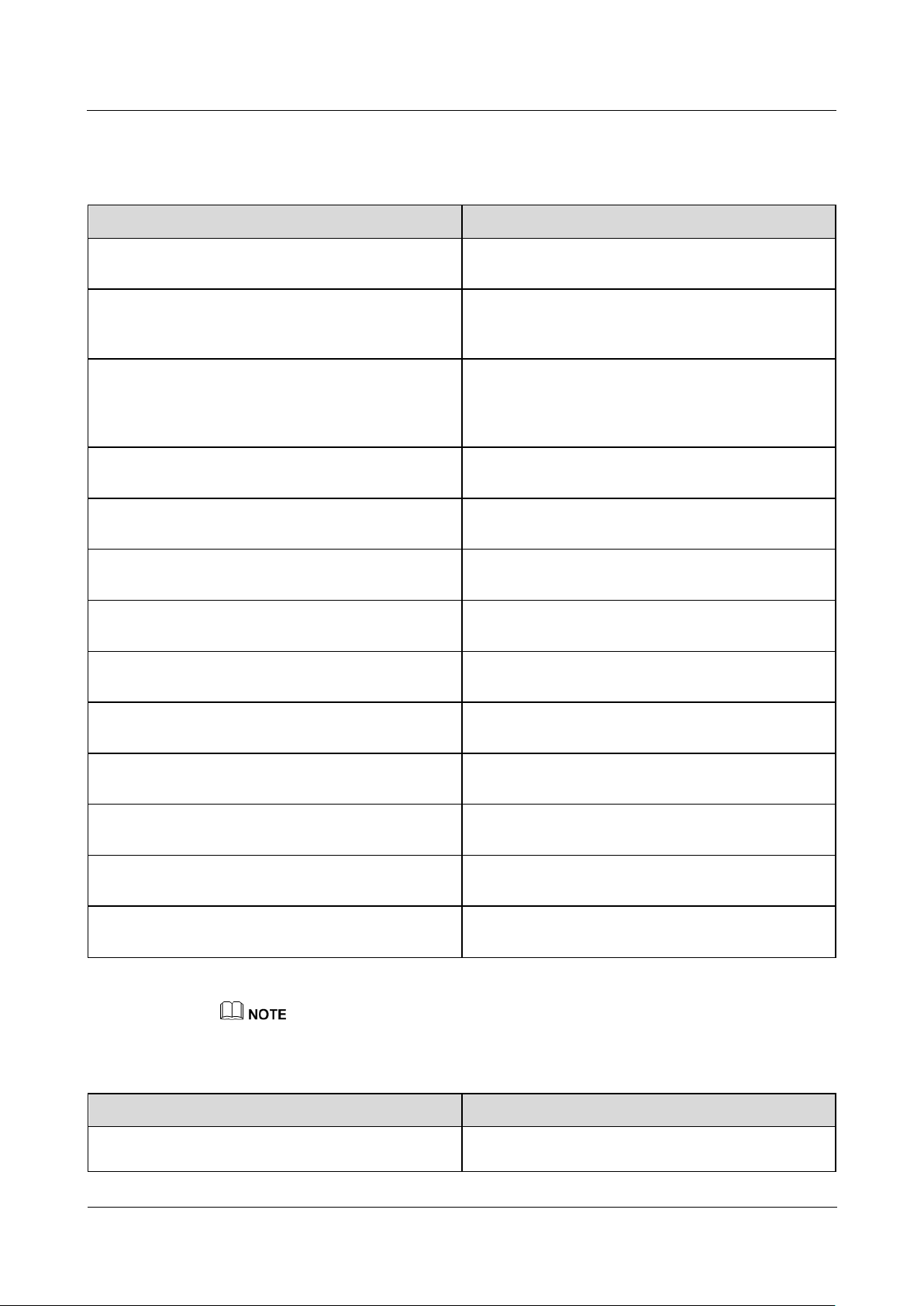
SmartLogger1000A
User Manual
6 WebUI Operations
Issue 02 (2019-01-15)
Copyright © Huawei Technologies Co., Ltd.
62
Parameter
Description
Unbalance voltage protection
Specifies the inverter protection threshold when the
power grid voltage is unbalanced.
Phase protection point
The Japanese standard requires that protection should
be triggered if an abrupt voltage phase change is
detected during passive islanding detection.
Phase angle offset protection
The standards of certain countries and regions require
that the inverter needs to be protected when the
three-phase angle offset of the power grid exceeds a
certain value.
10 minute OV protection
Specifies the 10-minute overvoltage protection
threshold.
10 minute OV protection time
Specifies the 10-minute overvoltage protection
duration.
Level-N OV protection
Specifies the level-N grid overvoltage protection
threshold.
Level-N OV protection time
Specifies the level-N grid overvoltage protection
duration.
Level-N UV protection
Specifies the level-N grid undervoltage protection
threshold.
Level-N UV protection time
Specifies the level-N grid undervoltage protection
duration.
Level-N OF protection
Specifies the level-N grid overfrequency protection
threshold.
Level-N OF protection time
Specifies the level-N grid overfrequency protection
duration.
Level-N UF protection
Specifies the level-N grid underfrequency protection
threshold.
Level-N UF protection time
Specifies the level-N grid underfrequency protection
duration.
Parameter
Description
LVRT
When the power grid voltage is abnormally low for a
short time, the inverter cannot disconnect from the
Protection Parameters
N is 1, 2, 3, 4, 5, or 6.
Feature Parameters
Page 70

SmartLogger1000A
User Manual
6 WebUI Operations
Issue 02 (2019-01-15)
Copyright © Huawei Technologies Co., Ltd.
63
Parameter
Description
power grid immediately and has to work for some
time. This is called LVRT.
LVRT triggering threshold
Specifies the threshold for triggering LVRT. The
threshold settings should meet the local grid standard.
LVRT undervoltage protection shield
Specifies whether to shield the undervoltage
protection function during LVRT.
LVRT reactive power compensation power factor
During LVRT, the inverter needs to generate reactive
power to support the power grid. This parameter is
used to set the reactive power generated by the
inverter.
For example, if you set LVRT reactive power
compensation power factor to 2, the reactive current
generated by the inverter is 20% of the rated current
when the AC voltage drops by 10% during LVRT.
HVRT
When the power grid voltage is abnormally high for a
short time, the inverter cannot disconnect from the
power grid immediately and has to work for some
time. This is called high voltage ride-through
(HVRT).
HVRT triggering threshold
Specifies the threshold for triggering HVRT. The
threshold settings should meet the local grid standard.
HVRT reactive power compensation power factor
During HVRT, the inverter needs to generate reactive
power to support the power grid. This parameter is
used to set the reactive power generated by the
inverter.
For example, if you set HVRT reactive power
compensation power factor to 2, the reactive current
generated by the inverter is 20% of the rated current
when the AC voltage increases by 10% during HVRT.
VRT grid voltage protection shield
Specifies whether to shield the
undervoltage/overvoltage protection function during
HVRT/LVRT.
Grid voltage transition triggering threshold
To meet the standards of certain countries and regions,
when the power grid voltage goes through transient
changes, the inverter cannot disconnect from the
power grid immediately and has to work for some
time. This is called transient voltage jump.
This parameter specifies the threshold for triggering
transient voltage jump.
Active islanding
Specifies whether to enable the active islanding
protection function.
Passive islanding
Specifies whether to enable the passive islanding
protection function.
Voltage rise suppression
The standards of certain countries and regions require
Page 71
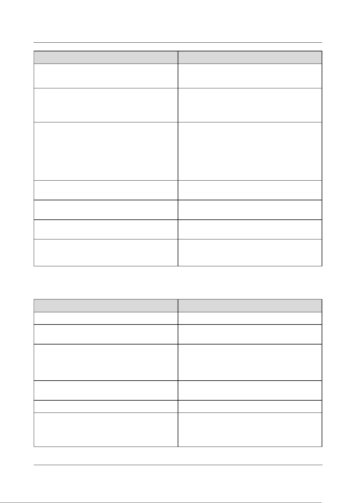
SmartLogger1000A
User Manual
6 WebUI Operations
Issue 02 (2019-01-15)
Copyright © Huawei Technologies Co., Ltd.
64
Parameter
Description
that the active power of the inverter be derated
according to a certain slope when the output voltage
exceeds a certain value.
Voltage rise suppression reactive adjustment point
The standards of certain countries and regions require
that the inverter must generate a certain amount of
reactive power when the output voltage exceeds a
certain value.
Voltage rise suppression active derating point
The standards of certain countries and regions require
that the active power of the inverter be derated
according to a certain slope when the output voltage
exceeds a certain value.
The value of Voltage rise suppression active
derating point must be greater than that of Voltage
rise suppression reactive adjustment point.
Frequency change rate protection
Specifies whether to protect the inverter when the
power grid frequency changes too fast.
Frequency change rate protection point
Specifies the frequency change rate protection
threshold.
Frequency change rate protection time
Specifies the frequency change rate protection
duration.
Soft start time after grid failure
Specifies the time for the power to gradually increase
when the inverter restarts after the power grid
recovers.
Parameter
Description
Active power change gradient
Adjusts the change speed of the inverter active power.
Fixed active power derated
Adjusts the active power output of the inverter based
on fixed values.
Active power percentage derating
Adjusts the active power output of the inverter based
on the percentage.
If this parameter is set to 100%, the inverter delivers
the maximum output power.
Reactive power change gradient
Adjusts the change speed of the inverter reactive
power.
Power factor
Adjusts the power factor of the inverter.
Overfrequency derating
If this parameter is enabled, the active power of the
inverter will be derated according to a certain slope
when the power grid frequency exceeds the frequency
that triggers overfrequency derating.
Power Adjustment Parameters
Page 72

SmartLogger1000A
User Manual
6 WebUI Operations
Issue 02 (2019-01-15)
Copyright © Huawei Technologies Co., Ltd.
65
Parameter
Description
Trigger frequency of over frequency derating
The standards of certain countries and regions require
that the output active power of the inverter be derated
when the power grid frequency exceeds a certain
value.
Quit frequency of over frequency derating
Specifies the frequency threshold for exiting
overfrequency derating.
Cutoff frequency of overfrequency derating
Specifies the frequency threshold for cutting off
overfrequency derating.
The parameter setting should meet the following
condition: Overfrequency derating ≤ Trigger
frequency of over frequency derating < Cutoff
frequency of overfrequency derating.
Cutoff power of overfrequency derating
Specifies the power threshold for cutting off
overfrequency derating.
Power recovery gradient of overfrequency derating
Specifies the power recovery gradient for
overfrequency derating.
Remote power schedule
If this parameter is set to Enable, the inverter
responds to the scheduling instruction from the
remote port.
If this parameter is set to Disable, the inverter does
not respond to the scheduling instruction from the
remote port.
Schedule instruction valid duration
Adjusts the duration within which the scheduling
instruction is valid.
If this parameter is set to 0, the scheduling instruction
is valid permanently.
Maximum apparent power
Specifies the output upper threshold for the maximum
apparent power to adapt to the capacity requirements
of standard and customized transformers.
Maximum active power
Specifies the output upper threshold for the maximum
active power to adapt to various market requirements.
Shutdown at 0% power limit
If this parameter is set to Enable, the inverter shuts
down after receiving the 0% power limit
instruction.
If this parameter is set to Disable, the inverter does
not shut down after receiving the 0% power limit
instruction.
Reactive power compensation (Q/S)
Adjusts the output reactive power of the inverter.
Reactive power output at night
In some specific application scenarios, a power grid
company requires the inverter to perform reactive
power compensation at night to ensure that the power
factor of the local power grid meets requirements.
This parameter is available only when Isolation is set
Page 73
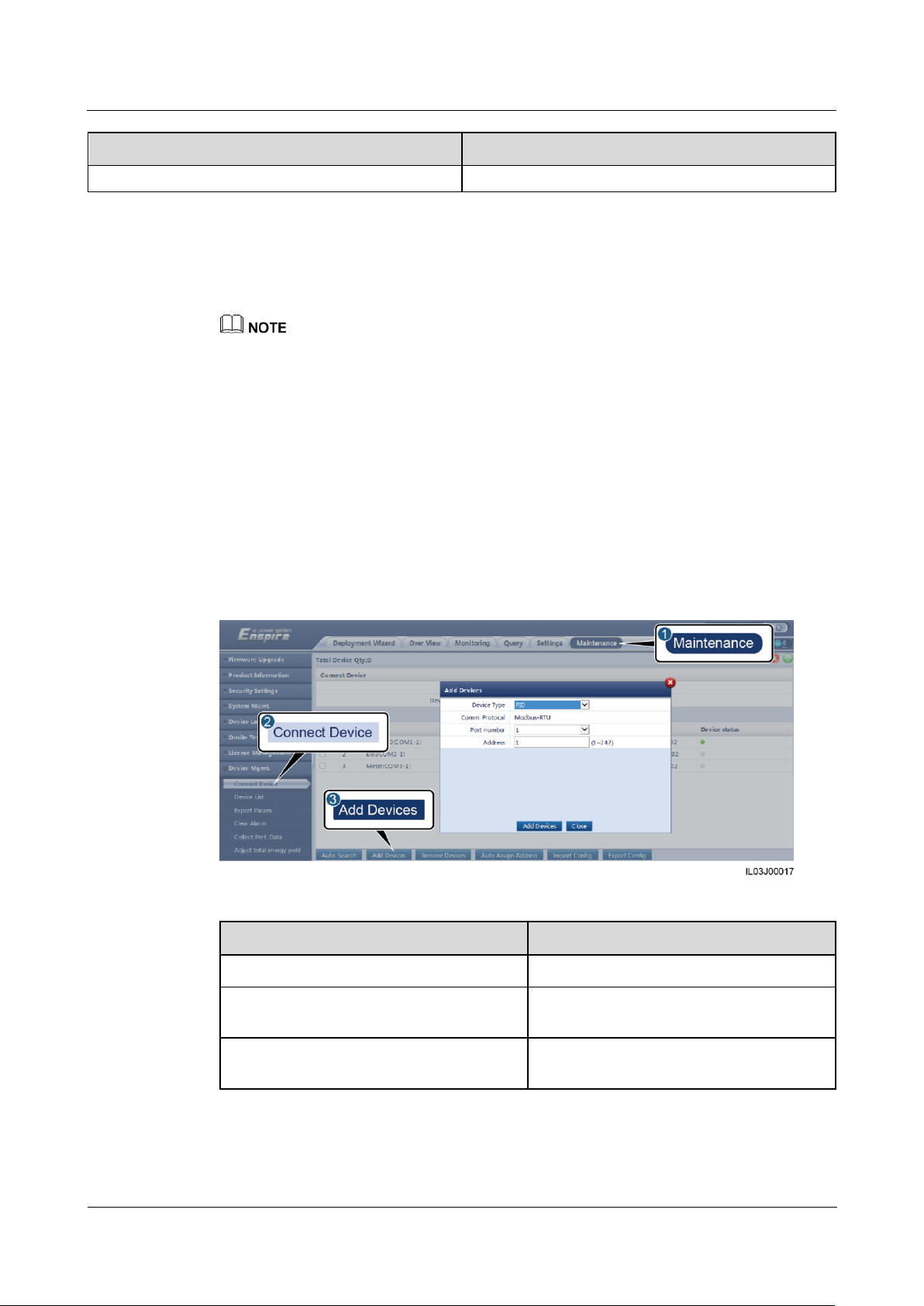
SmartLogger1000A
User Manual
6 WebUI Operations
Issue 02 (2019-01-15)
Copyright © Huawei Technologies Co., Ltd.
66
Parameter
Description
to Input ungrounded (with TF).
Parameter
Description
Device Type
Set this parameter to PID.
Port number
Set this parameter to the number of the
COM port connected to the PID module.
Address
Set this parameter to the communication
address of the PID module.
LVRT Characteristic Curve
On the LVRT Characteristic Curve tab page, configure the LVRT feature.
The SmartLogger supports only the curve configuration for LVRT that lasts no more than 10s. If a power
grid standard requires that LVRT be longer than 10s, LVRT Characteristic Curve is not displayed for
the grid code.
6.3.7 Setting PID Module Parameters
Procedure
Step 1 Log in as Advanced User or Special User and set access parameters.
Method 1: Click Auto Search to connect to the PID module.
Method 2: Click Add Devices, set access parameters, and click Add Devices.
Figure 6-19 Setting access parameters
Step 2 Log in as Advanced User, set running parameters, and click Submit.
Page 74

SmartLogger1000A
User Manual
6 WebUI Operations
Issue 02 (2019-01-15)
Copyright © Huawei Technologies Co., Ltd.
67
Figure 6-20 Setting running parameters
Parameter
Description
Offset mode
Specifies the offset mode of the PID
module.
Select Disable if the PID module is not
required.
Select N/PE if the PID module is
required to use voltage output from the
inductor virtual midpoint.
Select PV/PE if the PID module is
required to use voltage output from the
negative PV terminal. This mode is
applicable only to Huawei SUN8000.
In the SUN2000 scenario, Automatic
indicates the N/PE offset mode.
Output enabled
Specifies whether PID module output is
enabled.
PV type
Specifies the type of the PV module used in
the PV plant. For details about the PV
module type, consult the manufacturer.
PV/PE offset voltage
Specifies the DC output voltage when the
offset mode is set to PV/PE.
If the PV module type is P, set this
parameter to P-type. In this case, the
output voltage of the PID module is
positive.
If the PV module type is N, set this
parameter to N-type. In this case, the
output voltage of the PID module is
negative.
Operation Mode
Specifies the working mode of the PID
module.
Table 6-2 Running parameters of PID01
Page 75
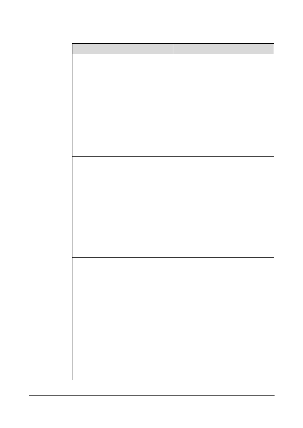
SmartLogger1000A
User Manual
6 WebUI Operations
Issue 02 (2019-01-15)
Copyright © Huawei Technologies Co., Ltd.
68
Parameter
Description
Commissioning mode: If Offset mode
is set to N/PE or PV/PE, and Output
enabled is set to Enable, the PID
module outputs data based on
Commissioning output voltage.
Normal mode: After the PID module
and inverter communicate with the
SmartLogger properly, the PID module
automatically runs.
NOTE
To check whether the PID module functions
properly, it is recommended that Operation
Mode be set to Commissioning upon first
power-on.
After checking that the PID module functions
properly, set Operation Mode to Normal.
Commissioning output voltage
Specifies the output voltage.
NOTE
After this parameter is set and the output from
the PID module becomes stable, use a multimeter
that is set to the DC position to measure the
three-phase (A, B, and C) voltages of the power
grid to the ground, and check whether the
voltages are the same as the configured values.
Maximum DC voltage
Specifies the PV-PE voltage when the
normal operation mode is used.
If the PV module type is P, the parameter
value indicates the highest DC voltage
between PV+ and PE. If the PV module
type is N, the parameter value indicates the
highest DC voltage between PV– and PE.
Maximum output voltage
Specifies the maximum output voltage of
the PID module.
If the offset mode is PV/PE, the parameter
value indicates the highest DC output
voltage between PV and PE. If the offset
mode is N/PE, the parameter value indicates
the highest DC output voltage between N
and PE.
IMD access
Specifies whether the PID module and
insulation monitor device (IMD) can
operate in cycle mode.
Only the IMDs of mainstream suppliers
such as DOLD and BENDER are supported,
and the IMDs must have enabled dry
contacts.
NOTICE
You can set Periodic PID runtime, Periodic
IMD runtime, and IMD control dry contact
Page 76

SmartLogger1000A
User Manual
6 WebUI Operations
Issue 02 (2019-01-15)
Copyright © Huawei Technologies Co., Ltd.
69
Parameter
Description
only when IMD access is set to Enable.
Periodic PID runtime
Specifies the operating time segment of the
PID module when the PID module and IMD
operate in cycle mode.
The IMD is shut down when the PID
module is operating.
Periodic IMD runtime
Specifies the operating time segment of the
IMD when the PID module and IMD
operate in cycle mode.
The PID module is standby when the IMD
is operating.
IMD control dry contact
Specifies the dry contact No. over which the
SmartLogger controls the IMD.
Set appropriate ports based on the cable
connections between the IMD and the
SmartLogger.
Clear data
Clears the active alarms and historical
alarms stored on the PID module.
You can select Clear data to clear active
alarms and historical alarms for the PID
module.
----End
6.3.8 Setting Power Meter Parameters
6.3.8.1 Setting DL/T645 Power Meter Parameters
Procedure
Step 1 Log in as Advanced User or Special User, set access parameters, and click Add Devices.
Page 77

SmartLogger1000A
User Manual
6 WebUI Operations
Issue 02 (2019-01-15)
Copyright © Huawei Technologies Co., Ltd.
70
Figure 6-21 Setting access parameters
Parameter
Description
Device Type
Set this parameter to Power Meter.
Comm.Protocal
Set this parameter to DL/T645.
Port number
Set this parameter to the number of the
COM port connected to the power meter.
Address
Set this parameter to the communication
address of the power meter.
Table ID
Set this parameter to the meter ID.
Parameter
Description
Protocol version
Select DL/T645-2007 or DL/T645-1997
based on the protocol version of the power
meter.
Number of lead bytes
Retain the default value unless otherwise
Step 2 Set running parameters and click Submit.
Figure 6-22 Setting running parameters
Page 78

SmartLogger1000A
User Manual
6 WebUI Operations
Issue 02 (2019-01-15)
Copyright © Huawei Technologies Co., Ltd.
71
Parameter
Description
specified.
Voltage change ratio
Set this parameter to 1 when the power
meter uploads a value once.
When the power meter uploads a value
twice, set this parameter based on the
actual transformer ratio.
Current change ratio
Parameter
Description
Intelligent Power Meter Type
Set this parameter to the corresponding
meter model.
Currently, the following meter models are
supported: ABB A44, Acrel PZ96L,
algodue UPM209, CHNT DTSU666,
Janitza UMG604, Lead LD-C83, MingHua
CRDM-830, NARUN PD510, NetBiter
CEWE, People RM858E, Schneider
PM1200, SFERE PD194Z, and Socomec
COUNTIS E43.
Voltage change ratio
Set this parameter to 1 when the power
meter uploads a value once.
When the power meter uploads a value
twice, set this parameter based on the
Current change ratio
----End
6.3.8.2 Setting Modbus-RTU Meter Parameters
Procedure
Step 1 Log in as Advanced User or Special User, set power meter parameters, and click Submit.
Figure 6-23 Setting power meter parameters
If the model of the connected device is displayed in the Intelligent Power Meter Type
drop-down list box, set parameters as follows.
Page 79

SmartLogger1000A
User Manual
6 WebUI Operations
Issue 02 (2019-01-15)
Copyright © Huawei Technologies Co., Ltd.
72
Parameter
Description
actual transformer ratio.
Parameter
Description
Intelligent Power Meter Type
Set this parameter to Other.
Read function code
Set this parameter to Read holding register
03H or Read holding register 04H based
on the protocol adopted by the vendor.
Read mode
The value can be Multiple read or Single
read.
Word ordering
Set this parameter to Big endian or Little
endian based on the protocol adopted by the
vendor.
Start address
If Read mode is set to Multiple read, set
the start address for reading.
End address
If Read mode is set to Multiple read, set
the end address for reading.
Voltage change ratio
Set this parameter to 1 when the power
meter uploads a value once.
When the power meter uploads a value
twice, set this parameter based on the
actual transformer ratio.
Current change ratio
Signal parameters
NOTE
Signal parameters include Signal Name, Signal
address, Number of Registers, Gain, Data
Type, and Unit.
Set this parameter based on the vendor
protocol.
NOTE
If the power meter can collect a signal, set Signal
address for the signal to the corresponding
register address. If the power meter cannot
collect a signal, set Signal address for the signal
to 65535.
If the connected power meter is of another model, set parameters as follows.
Step 2 Set access parameters and click Add Devices.
Page 80
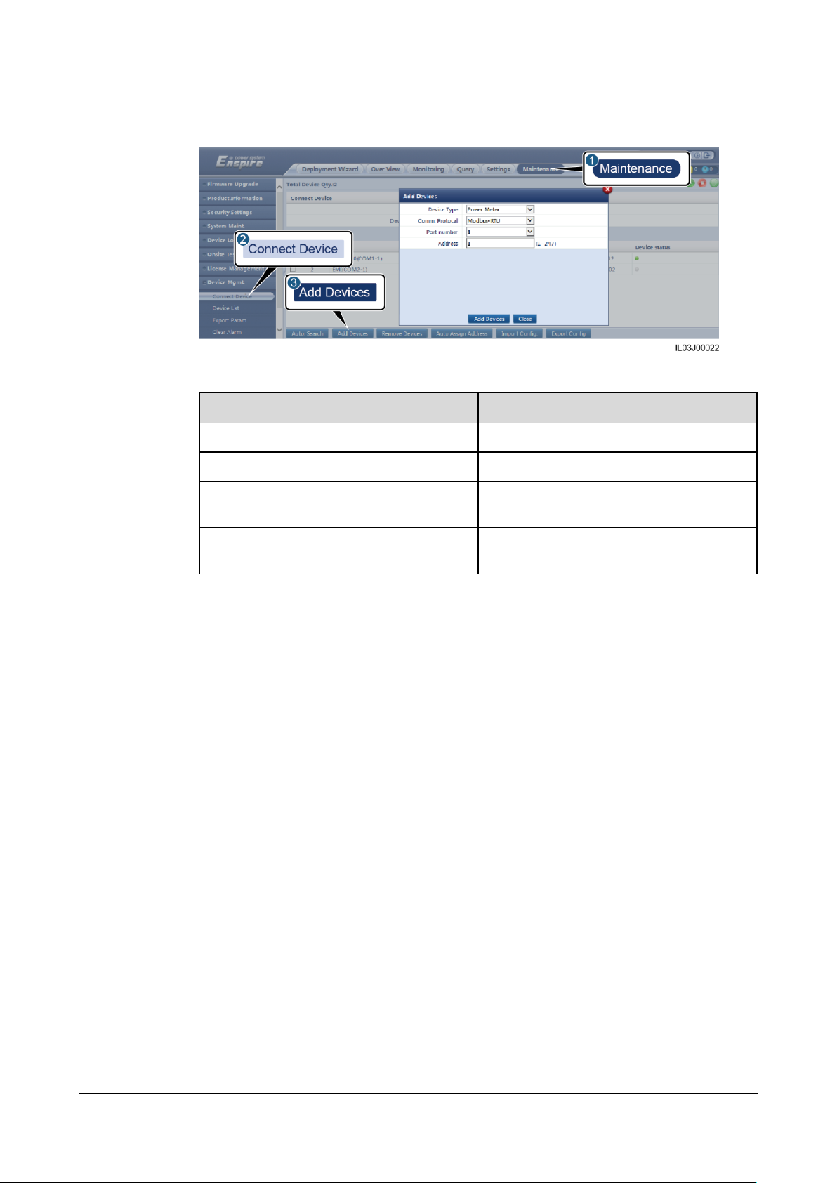
SmartLogger1000A
User Manual
6 WebUI Operations
Issue 02 (2019-01-15)
Copyright © Huawei Technologies Co., Ltd.
73
Figure 6-24 Setting access parameters
Parameter
Description
Device Type
Set this parameter to Power Meter.
Comm.Protocal
Set this parameter to Modbus-RTU.
Port number
Set this parameter to the number of the
COM port connected to the power meter.
Address
Set this parameter to the communication
address of the power meter.
----End
6.3.9 Setting EMI Parameters
6.3.9.1 Setting Modbus-RTU EMI Parameters
Procedure
Step 1 Log in as Advanced User or Special User, set access parameters, and click Add Devices.
Page 81
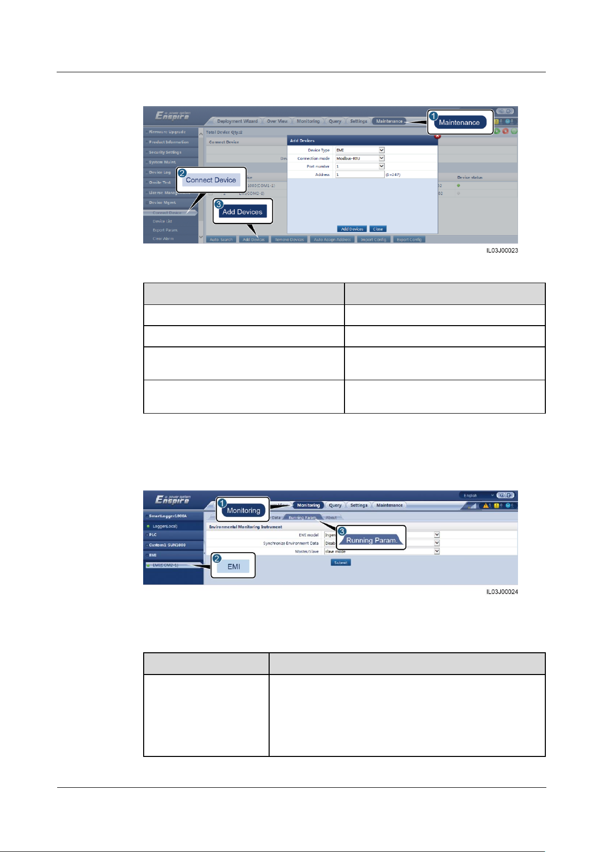
SmartLogger1000A
User Manual
6 WebUI Operations
Issue 02 (2019-01-15)
Copyright © Huawei Technologies Co., Ltd.
74
Figure 6-25 Setting access parameters
Parameter
Description
Device Type
Set this parameter to EMI.
Connection mode
Set this parameter to Modbus-RTU.
Port number
Set this parameter to the serial number of
the COM port connected to the EMI.
Address
Set this parameter to the communication
address of the EMI.
Parameter
Description
EMI Mode
Set this parameter to the model of the connected EMI.
Currently, the following EMI models are supported: ABB
VSN800-12, ABB VSN800-14, Gill MetPak Pro, Hukseflux
SRx, Ingenieurbüro Si-RS485TC, Kipp&Zonen SMPx, Lufft
WSx-UMB, Lufft WSx-UMB(external sensors), Meier-NT
ADL-SR, Meteo control SR20-D2, Rainwise PVmet-150,
Step 2 Log in asAdvanced User, set running parameters and click Submit.
Figure 6-26 Setting running parameters
If the model of the connected EMI is displayed in the EMI Mode drop-down list box, set
parameters as follows.
Page 82

SmartLogger1000A
User Manual
6 WebUI Operations
Issue 02 (2019-01-15)
Copyright © Huawei Technologies Co., Ltd.
75
Parameter
Description
Rainwise PVmet-200, Soluzione Solare SunMeter, JinZhou
LiCheng, JinZhou YangGuang(PC-4), Handan(RYQ-3).
Synchronize Environment
Data
You are advised to retain the default value Disable.
NOTE
When this parameter is set to Enable, the SmartLogger transmits the
wind speed and direction data to the inverter in a PV plant with the
tracking system.
Master/Slave
When the SmartLogger connects to multiple EMIs, set one of
them to master mode. The inverter performance data
displayed is the data of the EMI in master mode.
Parameter
Description
EMI Mode
Set this parameter to Sensor(ADAM).
Synchronize Environment Data
You are advised to retain the default value
Disable.
NOTE
When this parameter is set to Enable, the
SmartLogger transmits the wind speed and
direction data to the inverter in a PV plant with
the tracking system.
Master/Slave
When the SmartLogger connects to multiple
EMIs, set one of them to master mode. The
inverter performance data displayed is the
data of the EMI in master mode.
Read function code
Set this parameter to Read holding register
03H or Read holding register 04H based
on the protocol adopted by the vendor.
Data reporting mode
Set this parameter to Integer or Floating
point based on the protocol adopted by the
vendor.
Word ordering
Set this parameter to Big endian or Little
endian based on the protocol adopted by the
vendor.
Read mode
The value can be Multiple read or Single
read.
Start address
If Read mode is set to Multiple read, set
the start address for reading.
End address
If Read mode is set to Multiple read, set
the end address for reading.
Signal parameters
Set these parameters based on the vendor
If the connected EMI is a split EMI that supports Modbus-RTU, set parameters as
follows.
Page 83
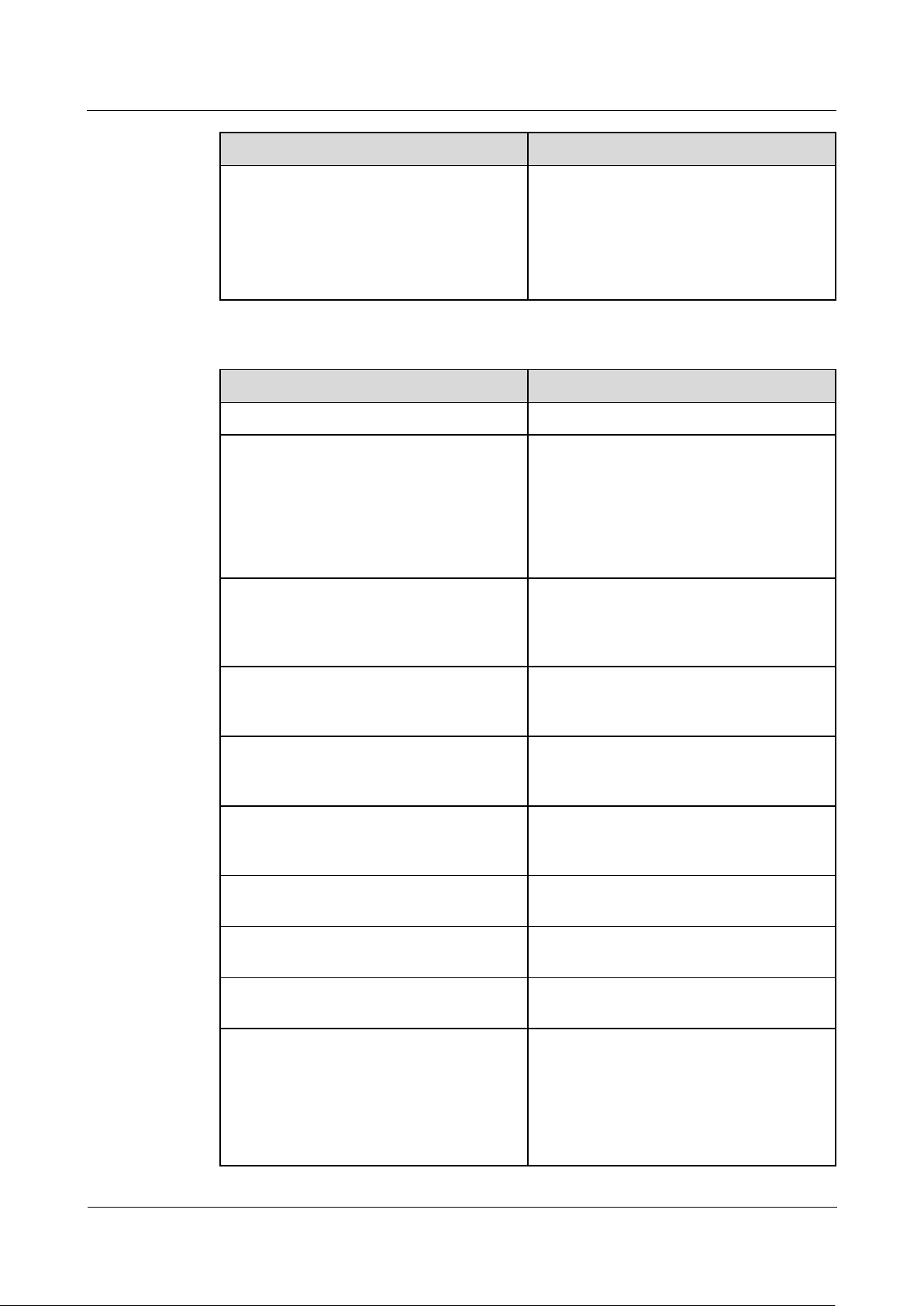
SmartLogger1000A
User Manual
6 WebUI Operations
Issue 02 (2019-01-15)
Copyright © Huawei Technologies Co., Ltd.
76
Parameter
Description
NOTE
Signal parameters include Signal Name, Signal
address, Lower Thres., Upper Thres., Spec,
Start (mV/mA), End (mV/mA), and Unit.
protocol.
NOTE
If the EMI can collect a signal, set Signal
address for the signal to the corresponding
register address. If the EMI cannot collect a
signal, set Signal address for the signal to
65535.
Parameter
Description
EMI Mode
Set this parameter to Other.
Synchronize Environment Data
You are advised to retain the default value
Disable.
NOTE
When this parameter is set to Enable, the
SmartLogger transmits the wind speed and
direction data to the inverter in a PV plant with
the tracking system.
Master/Slave
When the SmartLogger connects to multiple
EMIs, set one of them to master mode. The
inverter performance data displayed is the
data of the EMI in master mode.
Read function code
Set this parameter to Read holding register
03H or Read holding register 04H based
on the protocol adopted by the vendor.
Data reporting mode
Set this parameter to Integer or Floating
point based on the protocol adopted by the
vendor.
Word ordering
Set this parameter to Big endian or Little
endian based on the protocol adopted by the
vendor.
Read mode
The value can be Multiple read or Single
read.
Start address
If Read mode is set to Multiple read, set
the start address for reading.
End address
If Read mode is set to Multiple read, set
the end address for reading.
Signal parameters
NOTE
Signal parameters include Signal Name, Signal
address, Gain, Offset, and Unit.
Set these parameters based on the vendor
protocol.
NOTE
If the EMI can collect a signal, set Signal
address for the signal to the corresponding
register address. If the EMI cannot collect a
signal, set Signal address for the signal to
If the connected EMI is of another model, set parameters as follows.
Page 84
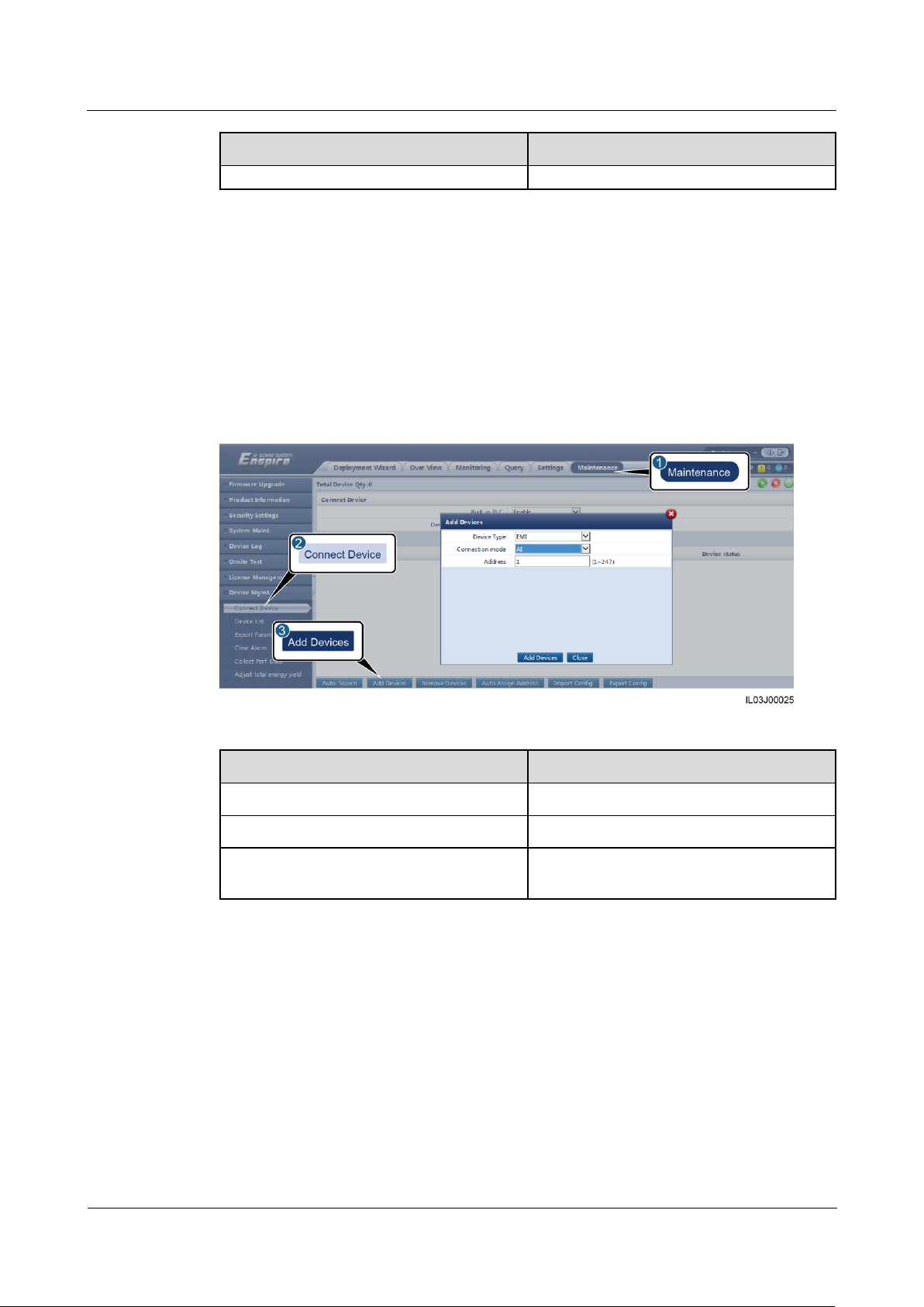
SmartLogger1000A
User Manual
6 WebUI Operations
Issue 02 (2019-01-15)
Copyright © Huawei Technologies Co., Ltd.
77
Parameter
Description
65535.
Parameter
Description
Device Type
Set this parameter to EMI.
Connection mode
Set this parameter to AI.
Address
Set this parameter to the communication
address of the EMI.
----End
6.3.9.2 Setting AI EMI Parameters
Procedure
Step 1 Log in as Advanced User or Special User, set access parameters, and click Add Devices.
Figure 6-27 Setting access parameters
Step 2 Log in as Advanced, set running parameters, and click Submit.
Page 85
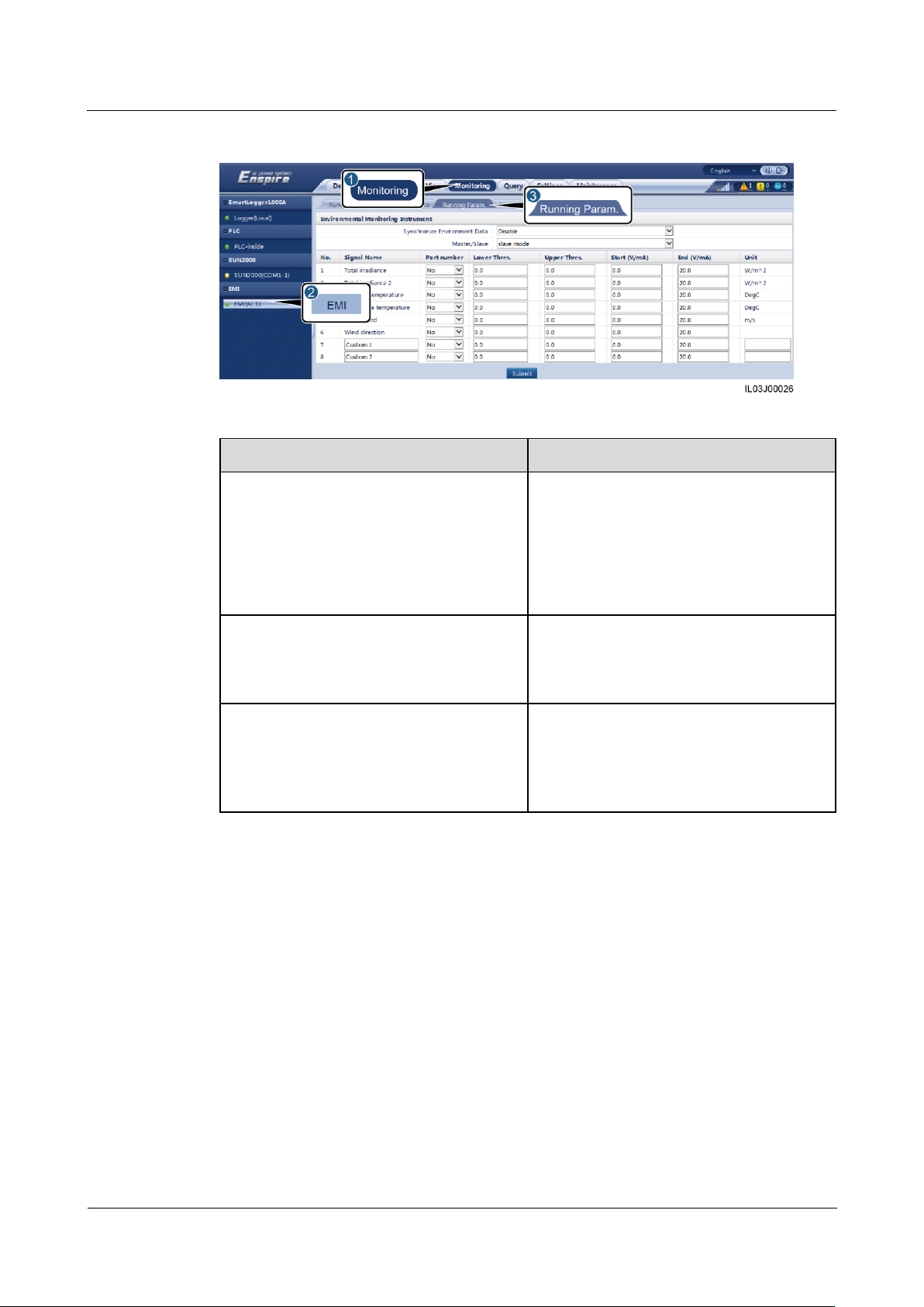
SmartLogger1000A
User Manual
6 WebUI Operations
Issue 02 (2019-01-15)
Copyright © Huawei Technologies Co., Ltd.
78
Figure 6-28 Setting running parameters
Parameter
Description
Synchronize Environment Data
You are advised to retain the default value
Disable.
NOTE
When this parameter is set to Enable, the
SmartLogger transmits the wind speed and
direction data to the inverter in a PV plant with
the tracking system.
Master/Slave
When the SmartLogger connects to multiple
EMIs, set one of them to master mode. The
inverter performance data displayed is the
data of the EMI in master mode.
Signal parameters
NOTE
Signal parameters include Signal Name, Port
number, Lower Thres., Upper Thres., Start
(V/mA), End (V/mA), and Unit.
Set these parameters as required.
NOTE
When you need to change the configured port
number, set Port number to No first, then to the
required port number.
----End
6.3.10 Setting IEC103 Device Parameters
Description
An IEC103 device supports two data transmission modes:
Transparent transmission mode: When connecting to the NMS, the SmartLogger
transparently transmits the IEC103 device information to the NMS. The SmartLogger
does not parse the IEC103 device data.
Parsing mode: The IEC103 device is connected to the SmartLogger, and the
SmartLogger parses the IEC103 device data.
Page 86
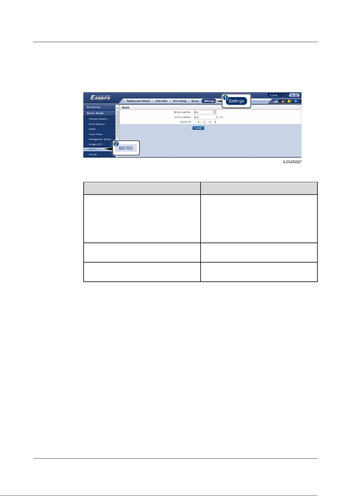
SmartLogger1000A
User Manual
6 WebUI Operations
Issue 02 (2019-01-15)
Copyright © Huawei Technologies Co., Ltd.
79
Transparent Transmission Mode
Parameter
Description
IEC103 port No.
Set this parameter based on the COM port
connected to the device.
NOTE
RS485-1 to RS485-3 correspond to
communications ports COM1 to COM3
respectively.
IEC103 address
Set this parameter to the IEC103 device
address.
IEC103 IP
The value must be the same as the IP
address of the NMS.
Step 1 Log in as Advanced User, set IEC103 parameters, and click Submit.
Figure 6-29 Setting IEC103 parameters
----End
Parsing Mode
The SmartLogger can connect to third-party devices that support IEC103, such as the relay
protection or monitoring device like the box-type transformer. The protocol information
points vary depending on vendors. Therefore, you need to obtain a protocol information file
in .cfg format from Huawei and import the file into the SmartLogger for successfully
connecting to a custom device.
The supported device types are IEC103 device 1 to IEC103 device 5. The corresponding
configuration file names are iec103_equip_custom_1.cfg to iec103_equip_custom_5.cfg.
Multiple devices of the same type can be connected.
Step 1 Log in as Advanced User or Special User, configure a protocol information point file in .cfg
format, and import the file to the SmartLogger.
Page 87
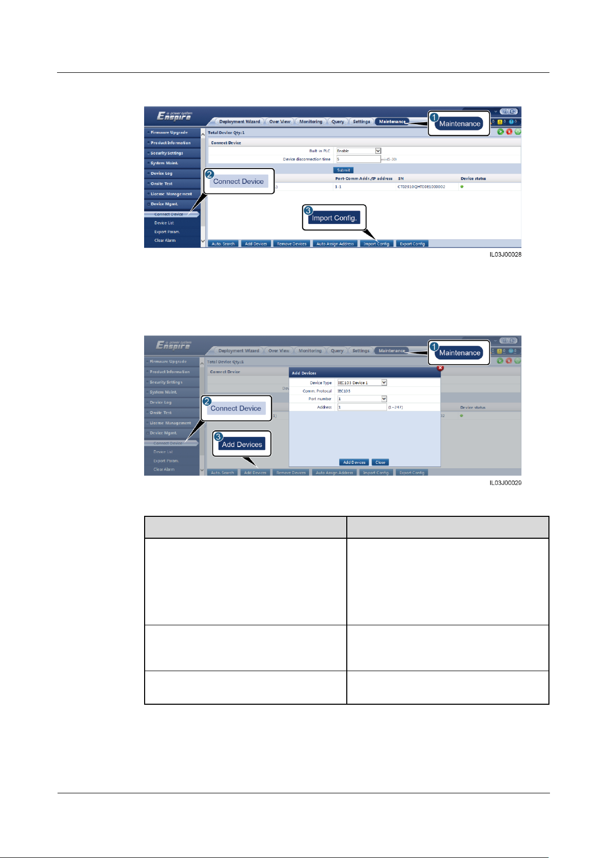
SmartLogger1000A
User Manual
6 WebUI Operations
Issue 02 (2019-01-15)
Copyright © Huawei Technologies Co., Ltd.
80
Figure 6-30 Importing configuration
Parameter
Description
Device Type
The value can be IEC103 Device 1 to
IEC103 Device 5.
Select a value based on the configuration
file. For example, if
iec103_equip_custom_1.cfg needs to be
imported, select IEC103 Device 1.
Port number
Set this parameter to the serial number of
the COM port connected to the IEC103
device.
Address
Set this parameter to the communication
address of the IEC103 device.
Step 2 Set access parameters and click Connect Device.
Figure 6-31 Setting access parameters
Step 3 Log in as Common User, Advanced User, or Special User, set device monitoring
parameters, and click Submit.
Page 88
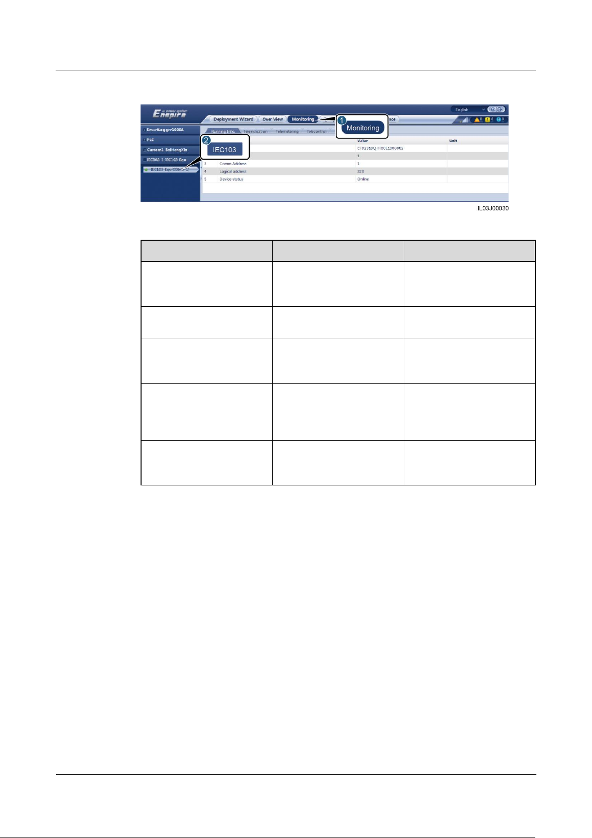
SmartLogger1000A
User Manual
6 WebUI Operations
Issue 02 (2019-01-15)
Copyright © Huawei Technologies Co., Ltd.
81
Figure 6-32 Device monitoring
Tab
Function
Description
Running Info.
View the running
information about the
IEC103 device.
Teleindication
View the device status, such
as the switch status.
-
Telemetering
View the real-time analog
data of the device, such as
the voltage.
-
Telecontrol
Set the status control
parameters, such as the
parameters for turning on or
off switches.
Set the parameters on the
tab page as required.
Teleadjust
Set analog parameters, for
example, set voltage
protection parameters.
Set the parameters on the
tab page as required.
----End
6.3.11 Setting Parameters for a Custom Device
Context
The SmartLogger can connect to third-party devices supporting the Modbus-RTU protocol,
such as the box-type transformer and EMI. The protocol information points vary depending
on vendors. Therefore, you need to configure a protocol information file in .cfg format and
import the file into the SmartLogger for successfully connecting to a custom device.
The supported device types are custom device 1 to custom device 5. The corresponding
configuration file names are modbus_equip_custom_1.cfg to modbus_equip_custom_5.cfg.
Multiple devices of the same type can be connected.
Page 89
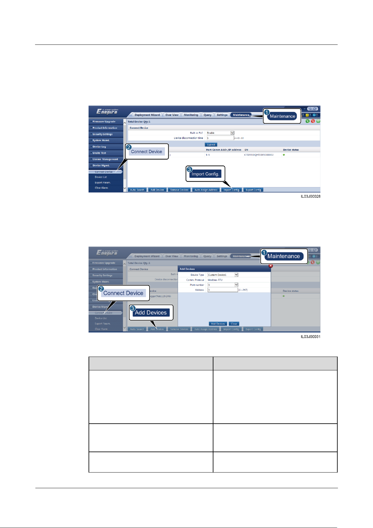
SmartLogger1000A
User Manual
6 WebUI Operations
Issue 02 (2019-01-15)
Copyright © Huawei Technologies Co., Ltd.
82
Procedure
Parameter
Description
Device Type
The value can be Custom Device 1 to
Custom Device 5.
Select a value based on the configuration
file. For example, if
modbus_equip_custom_1.cfg needs to be
imported, select Custom Device 1.
Port number
Set this parameter to the serial number of
the COM port connected to the custom
device.
Address
Set this parameter to the communication
address of the custom device.
Step 1 Log in as Advanced User or Special User, configure a protocol information point file in .cfg
Step 2 Set access parameters and click Add Devices.
format, and import the file to the SmartLogger.
Figure 6-33 Importing configuration
Figure 6-34 Setting access parameters
Page 90
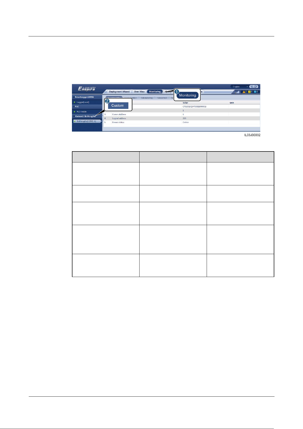
SmartLogger1000A
User Manual
6 WebUI Operations
Issue 02 (2019-01-15)
Copyright © Huawei Technologies Co., Ltd.
83
Tab
Function
Description
Running Info.
View the running
information about the
custom device.
Teleindication
View the device status, such
as the switch status.
-
Telemetering
View the real-time analog
data of the device, such as
the voltage.
-
Telecontrol
Set the status control
parameters, such as the
parameters for turning on or
off switches.
Set the parameters on the
tab page as required.
Teleadjust
Set analog parameters, for
example, set voltage
protection parameters.
Set the parameters on the
tab page as required.
Step 3 Log in as Common User, Advanced User, or Special User, set device monitoring
parameters, and click Submit.
Figure 6-35 Device monitoring
----End
6.4 Power Grid Scheduling
6.4.1 Power Adjustment Description
According to standard requirements, the SmartLogger can reliably adjust power for the
connected inverters in real time to ensure that the PV plant can respond to requirements of the
power grid company in a timely manner.
Page 91
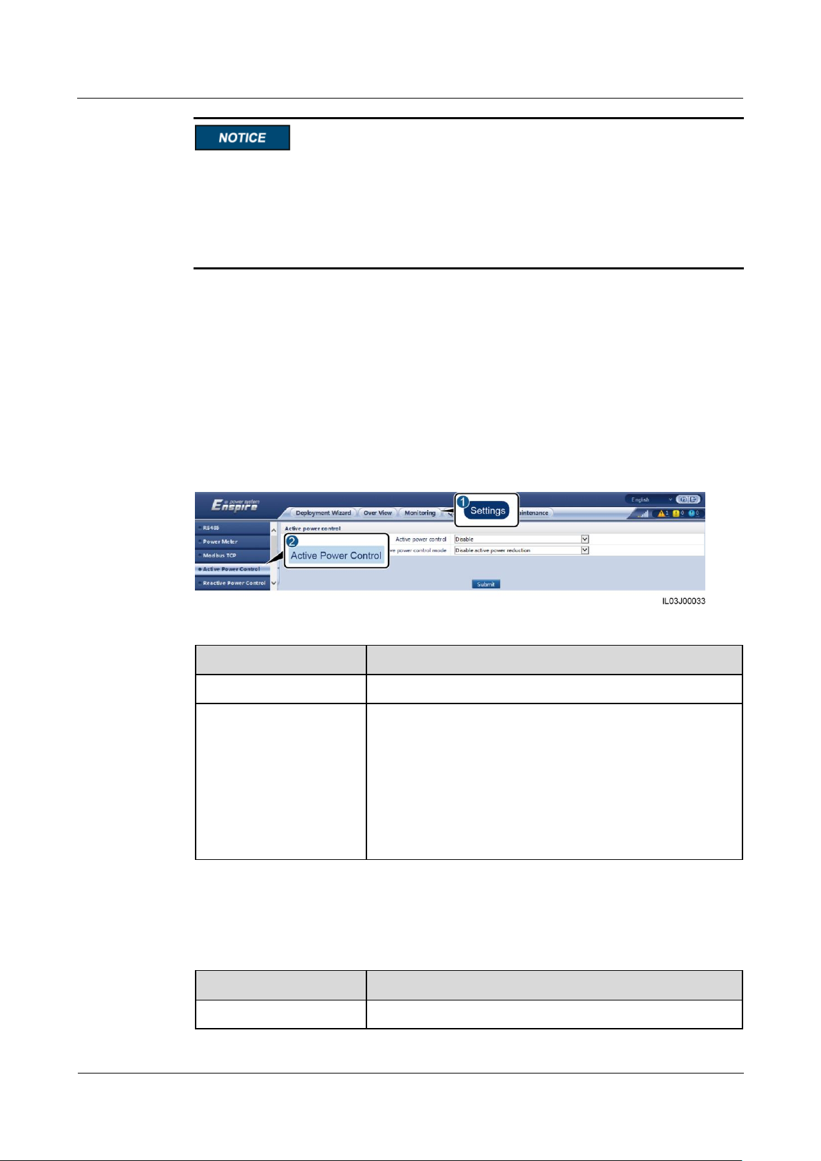
SmartLogger1000A
User Manual
6 WebUI Operations
Issue 02 (2019-01-15)
Copyright © Huawei Technologies Co., Ltd.
84
Parameter
Description
Active power control
Specifies whether to enable active power control.
Active power control
mode
Specifies the active power control mode. The following
modes are supported:
Disable active power reduction
Dry contact remote control
Percentage fix limitation
Remote scheduling
Remote output control
Parameter
Description
Active power control
Set this parameter to Enable.
To ensure that the SmartLogger will deliver scheduling commands to the connected
inverters, you must enable active or reactive power control before adjusting the active or
reactive power for a PV plant.
If you disable active or reactive power control, the SmartLogger will not deliver
scheduling commands to the connected inverters and the inverters will retain their status
after the previous change.
6.4.2 Setting Active Power Control
If the PV plant has requirements of power limitation, the power grid scheduling personnel
should limit the active power or disable all the active power for the PV plant, that is, to enable
the active power derating mode.
Step 1 Log in as Special User, and choose Monitoring > SUN2000 > Running Param. > Power
Adjustment. On the displayed page, ensure that Remote power schedule is set to Enable.
Step 2 Set the parameters for active power control and click Submit.
Figure 6-36 Active power control
----End
Disabling Active Power Reduction
Page 92

SmartLogger1000A
User Manual
6 WebUI Operations
Issue 02 (2019-01-15)
Copyright © Huawei Technologies Co., Ltd.
85
Parameter
Description
Active power control
mode
If this parameter is set to Disable active power reduction,
the inverter runs at full load.
Parameter
Description
Active power control
Set this parameter to Enable.
Active power control
mode
Set this parameter to Dry contact remote control.
DI parameters
NOTE
DI parameters include DI1,
DI2, DI3, DI4, and
Percentage(%).
Sixteen levels are supported for the active power derating
percentage.
"√" indicates low level. When connecting to DI–, the four
DI+ ports of the SmartLogger are low-level ports. If not
connected, the ports are high-level ports.
The percentage levels of DI1–DI4 should differ from each
other. Otherwise, an abnormal command will be
generated.
If the actual input DI signal is inconsistent with that
configured on the WebUI, the SmartLogger controls the
inverter to work at full load and the Abnormal Active
Schedule alarm is raised.
Parameter
Description
Active power control
Set this parameter to Enable.
Active power control
mode
Set this parameter to Percentage fix limitation to control the
maximum power output of the inverter in different periods of
a day.
Dry Contact Remote Control
Before setting this function, ensure that the DI port custom control is not occupied.
Otherwise, the setting fails.
Before setting this function, ensure that the SmartLogger is correctly connected to a ripple
control receiver.
Percentage Fix Limitation
The SmartLogger provides simplified active power percentage configuration as well as power
control automation, that is, to automatically adjust the active power derating percentage in
different periods of a day.
Page 93

SmartLogger1000A
User Manual
6 WebUI Operations
Issue 02 (2019-01-15)
Copyright © Huawei Technologies Co., Ltd.
86
Parameter
Description
Start time
If the inverter needs to run with specified maximum power in
certain periods of a day, add setting records based on site
requirements.
When multiple time points are set, the inverter will run with
the maximum power specified for the time point that is earlier
than and the closest to the current system time. For example,
if you add 00:00:00 and 12:00:00 on the WebUI and the
current system current is 14:30:00, the inverter will run with
the maximum power specified for 12:00:00.
Percentage(%)
Parameter
Description
Active power control
Set this parameter to Enable.
Active power control
mode
Set this parameter to Remote scheduling.
The SmartLogger parses the scheduling command delivered
by the upper-layer NMS to valid instruction data that can be
identified by the inverters in the PV plant and delivers the
data to all inverters connected to the SmartLogger.
As the Remote scheduling mode has a higher priority, the
SmartLogger automatically changes Active power control
mode to Remote scheduling after receiving a scheduling
command from the upper-layer NMS.
Schedule strategy
The value can be Disable, Strategy 1, or Strategy 2.
Disable: The SmartLogger controls the inverter to work at
full load and will not receive scheduling commands sent
by the NMS.
Strategy 1: Open-loop scheduling policy. That is, the
SmartLogger evenly allocates the power value from the
scheduling and delivers the average value to each inverter,
which then operates with the specific power. The
adjustment value delivered by the SmartLogger is
constant. If Adjustment coefficient is set, the power value
will be sent to the inverter after being multiplied by the
preset coefficient.
Strategy 2: The customized function is provided for a site.
Set Overshoot, Adjustment period, and Adjustment
deadband based on the scheduling requirements of the
site.
Remote Scheduling
The NMS or independent power adjustment device sends scheduling commands over the
communications port that works with Modbus-TCP or IEC104, without the need of user
configuration or operation. The SmartLogger can automatically switch between scheduling
modes and send scheduling commands.
Page 94

SmartLogger1000A
User Manual
6 WebUI Operations
Issue 02 (2019-01-15)
Copyright © Huawei Technologies Co., Ltd.
87
Remote Output Control
Path
Parameter
Description
Settings > User
Param. >
Date&Time
Clock source
Set this parameter to NTP.
Server
Set this parameter to the IP address or domain
name of the server for time synchronization.
NTP
synchronization
test
You can click this button to check the time
synchronization status.
Path
Parameter
Description
Settings > Active
Power Control
Active power
control
Set this parameter to Enable.
Active power
control mode
Set this parameter to Remote output control.
Control area
Set this parameter to the area where the
remote output control function is used. To
enable the function in some areas, the license
needs to be imported and enabled.
Output control
duration
Set this parameter to the time required for the
inverter to change its output power from 0%
to 100% or from 100% to 0%.
Remote output
control server
Set this parameter to the IP address or domain
name of the server.
Enable certificate
Determine whether to import and enable a
certificate based on the actual situation.
Step 1 Log in as Advanced User and synchronize the clock source of the server.
Step 2 Log in as Special User and set remote output control parameters.
If the connection between the SmartLogger and the server is abnormal, obtain the output control file
in .data format from the website of the power company and import the file.
After the SmartLogger connects to the server, you can export the relevant file.
----End
6.4.3 Setting Reactive Power Control
Large-scale PV plants are required to adjust the voltage at the grid-tied point. Power grid
scheduling personnel enable a PV plant to absorb or add reactive power at the grid-tied point,
that is, to enable the reactive power compensation, based on the real-time reactive power
transmission status in the power grid.
Page 95

SmartLogger1000A
User Manual
6 WebUI Operations
Issue 02 (2019-01-15)
Copyright © Huawei Technologies Co., Ltd.
88
Step 1 Log in as Special User, and choose Monitoring > SUN2000 > Running Param. > Power
Parameter
Description
Reactive Power Control
Specifies whether to enable reactive power
control.
Reactive power control mode
Specifies the reactive power control mode.
The following modes are supported:
Disable reactive power output
Dry contact remote control
Reactive power fix control
Power factor fix control
Q-U characteristic curve
cos(Phi)-P/Pn characteristic curve
Q-U hysteresis curve(CEI0-16)
Remote scheduling
Pwr factor closed-loop control
Distributed power factor closed-loop
control
Parameter
Description
Reactive Power Control
Set this parameter to Enable.
Reactive power control mode
If the PV plant is not required to adjust the
voltage at the grid-tied point or perform
reactive power compensation, inverters can
run with only active power output. In this
case, set this parameter to Disable reactive
power output.
Adjustment. On the displayed page, ensure that Remote power schedule is set to Enable.
Step 2 Set the parameters for reactive power control and click Submit.
Figure 6-37 Reactive power control
----End
Disabling Reactive Power Output
Page 96
SmartLogger1000A
User Manual
6 WebUI Operations
Issue 02 (2019-01-15)
Copyright © Huawei Technologies Co., Ltd.
89
Parameter
Description
Reactive Power Control
Set this parameter to Enable.
Reactive power control mode
Set this parameter to Dry contact remote
control.
DI parameters
NOTE
DI parameters include DI1, DI2, DI3, DI4, and
Power factor.
Sixteen levels are supported for power
factors.
"√" indicates low level. When
connecting to DI–, the four DI+ ports of
the SmartLogger are low-level ports. If
not connected, the ports are high-level
ports.
The percentage levels of DI1–DI4
should differ from each other.
Otherwise, an abnormal command is
generated.
If the actual input DI signal is
inconsistent with that configured on the
WebUI, the SmartLogger controls the
inverter to work at full power and the
Abnormal Reactive Schedule alarm is
raised.
Parameter
Description
Reactive Power Control
Set this parameter to Disable.
Reactive power control mode
If the PV array is required to generate
constant reactive power at a specified time,
set this parameter to Reactive power fix
control.
Start time
If the inverter is required to run with a
specified maximum power in certain periods
of a day, add setting records based on site
Reactive power (kVar)
Dry Contact Remote Control
Before setting this function, ensure that the DI port is not occupied. Otherwise, the setting
fails.
Before setting this function, ensure that the SmartLogger is correctly connected to a ripple
control receiver.
Reactive Power Fix Control
Page 97
SmartLogger1000A
User Manual
6 WebUI Operations
Issue 02 (2019-01-15)
Copyright © Huawei Technologies Co., Ltd.
90
Parameter
Description
requirements.
When multiple time points are set, the
inverter will run with the maximum power
specified for the time point that is earlier
than and the closest to the current system
time. For example, if you add 00:00:00 and
12:00:00 on the WebUI and the current
system current is 14:30:00, the inverter will
run with the maximum power specified for
12:00:00.
Parameter
Description
Reactive Power Control
Set this parameter to Enable.
Reactive power control mode
If the PV plant is required to generate a
constant power factor at the grid-tied point
and the inverter is required to adjust the
real-time reactive power based on the preset
power factor, set this parameter to Power
factor fix control.
Start time
If the inverter is required to run with a
specified power factor in certain periods of
a day, add setting records based on site
requirements.
When multiple time points are set, the
inverter will run with the maximum power
specified for the time point that is earlier
than and the closest to the current system
time. For example, if you add 00:00:00 and
12:00:00 on the WebUI and the current
system current is 14:30:00, the inverter will
run with the maximum power specified for
12:00:00.
Power factor
Power Factor Fix Control
Q-U Characteristic Curve
If you do not need the SmartLogger to send remote reactive power control commands, you
can configure the characteristic curve as a substitute. The SmartLogger delivers the values
configured for the characteristic curve to the inverter, which then operates according to the
configuration. The SmartLogger no longer adjusts the values.
Page 98
SmartLogger1000A
User Manual
6 WebUI Operations
Issue 02 (2019-01-15)
Copyright © Huawei Technologies Co., Ltd.
91
Parameter
Description
Reactive Power Control
Set this parameter to Enable.
Reactive power control mode
Set this parameter to Q-U characteristic
curve.
Reactive power adjustment time
Specifies the change interval of the reactive
power for a grid-tied point.
Percents of trigger frequency
Under a specific grid code, after you set this
parameter, the characteristic curve takes
effect only when the actual output active
power of the inverter is greater than the
preset value.
Characteristic curve points
Specifies the number of characteristic curve
points.
The characteristic curve supports a
maximum of 10 valid points.
U/Un(%)
When configuring the curve, ensure that the
U/Un(%) value of a point is greater than the
U/Un(%) value of the previous point.
Otherwise, the message indicating invalid
input will be displayed.
Q/S
Configure the characteristic curve under instructions from professionals to ensure that the
inverter works properly.
The Q-U characteristic curve control mode is to dynamically adjust the ratio Q/S of output
reactive power to apparent power in accordance with the ratio U/Un(%) of the actual grid
voltage to the rated grid voltage.
cos(Phi)-P/Pn Characteristic Curve
If you do not need the SmartLogger to send remote reactive power control commands, you
can configure the characteristic curve as a substitute. The SmartLogger delivers the values
configured for the characteristic curve to the inverter, which then operates according to the
configuration. The SmartLogger no longer adjusts the values.
Configure the characteristic curve under instructions from professionals to ensure that the
inverter works properly.
The cos(Phi)-P/Pn characteristic curve control mode is to dynamically adjust the power factor
cos(Phi) in accordance with the P/Pn (%) based on the VDE-4105 and BDEW German
standards.
Page 99
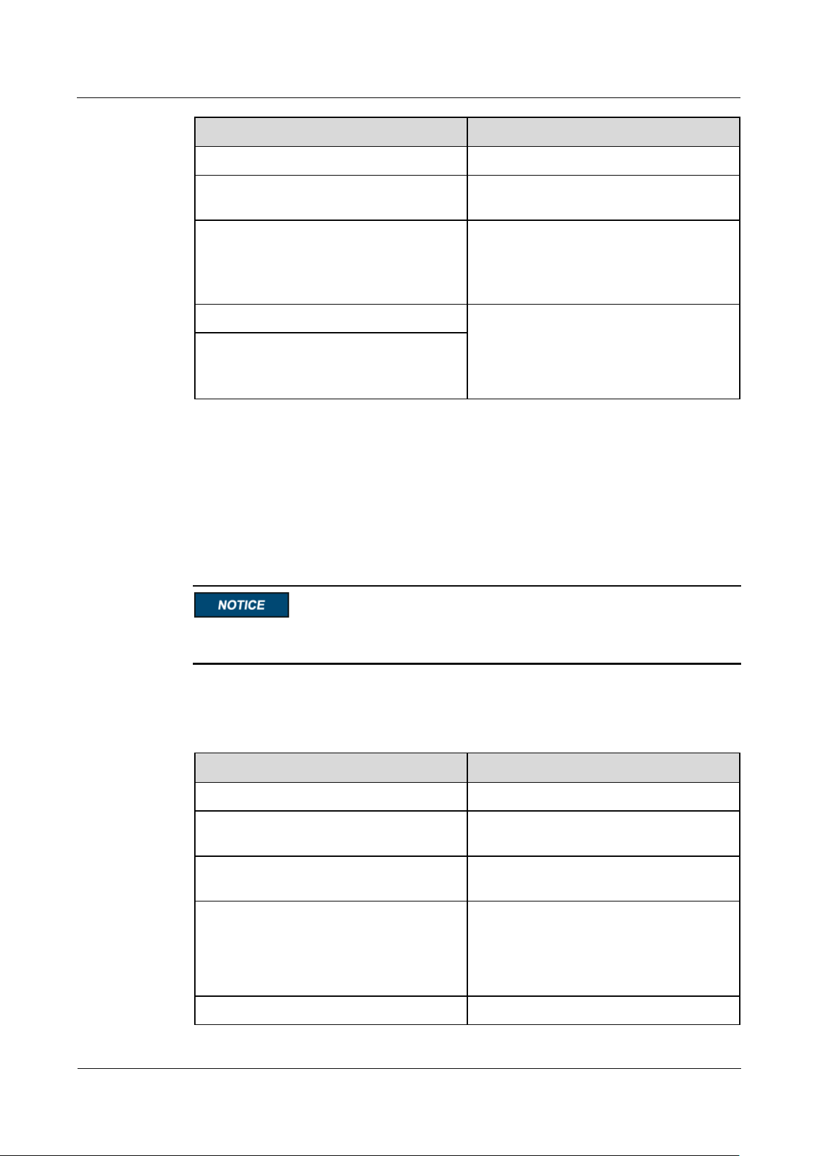
SmartLogger1000A
User Manual
6 WebUI Operations
Issue 02 (2019-01-15)
Copyright © Huawei Technologies Co., Ltd.
92
Parameter
Description
Reactive Power Control
Set this parameter to Enable.
Reactive power control mode
Set this parameter to cos(Phi)-P/Pn
characteristic curve.
Characteristic curve points
Specifies the number of characteristic curve
points.
The characteristic curve supports a
maximum of 10 valid points.
U/Un(%)
When configuring the curve, ensure that the
P/Pn(%) value of a point is greater than the
P/Pn(%) value of the previous point.
Otherwise, the message indicating invalid
input will be displayed.
cosφ
Parameter
Description
Reactive Power Control
Set this parameter to Enable.
Reactive power control mode
Set this parameter to Q-U hysteresis
curve(CEI0-16).
Reactive power adjustment time
Specifies the change interval of the reactive
power for a grid-tied point.
Percents of trigger frequency
Under a specific grid code, after you set this
parameter, the characteristic curve takes
effect only when the actual output active
power of the inverter is greater than the
preset value.
U/Un(%)
When configuring the curve, ensure that the
Q-U Hysteresis Curve (CEI0-16)
If you do not need the SmartLogger to send remote reactive power control commands, you
can configure the characteristic curve as a substitute. The SmartLogger delivers the values
configured for the characteristic curve to the inverter, which then operates according to the
configuration. The SmartLogger no longer adjusts the values.
Configure the characteristic curve under instructions from professionals to ensure that the
inverter works properly.
The Q-U hysteresis curve (CEI0-16) control mode is the Italian standard CEI0-16 version of
the Q-U characteristic curve. It dynamically adjusts the output reactive power of the inverter
in accordance with the ratio of the actual voltage to the rated voltage. The final value should
be in the form of Q/S.
Page 100
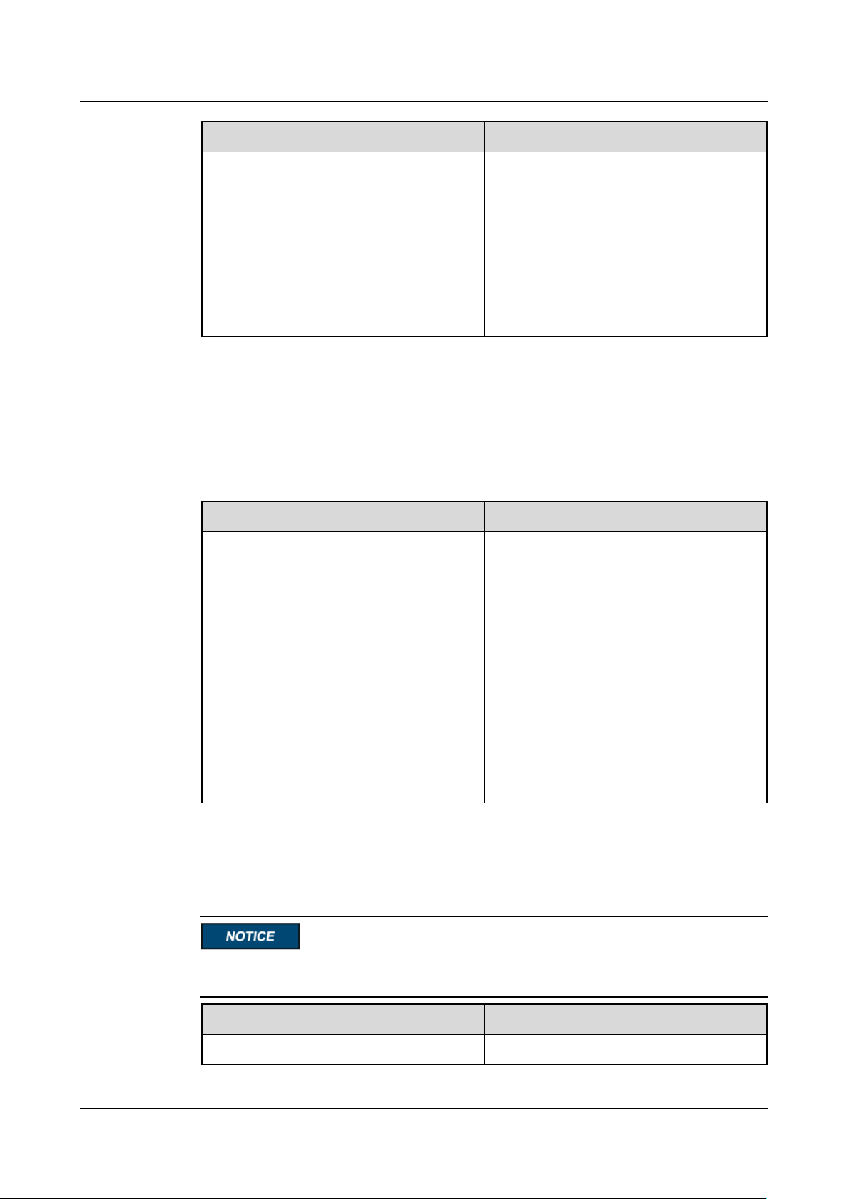
SmartLogger1000A
User Manual
6 WebUI Operations
Issue 02 (2019-01-15)
Copyright © Huawei Technologies Co., Ltd.
93
Parameter
Description
Q/S
U/Un(%) value of a point is greater than the
U/Un(%) value of the previous point.
Otherwise, the message indicating invalid
input will be displayed.
When configuring the curve, ensure that the
Q/S values at points A and B are the same
and set in sequence, and that the Q/S values
at points C and D are the same and set in
sequence. Otherwise, a message indicating
indicating invalid input is displayed.
Parameter
Description
Reactive Power Control
Set this parameter to Enable.
Reactive power control mode
As the Remote scheduling mode has a
higher priority, the SmartLogger
automatically changes Reactive power
control mode to Remote scheduling after
receiving a scheduling command from the
upper-layer NMS.
If this parameter is set to Remote
scheduling, the SmartLogger parses the
scheduling command delivered by the
upper-layer NMS to valid instruction data
that can be identified by the inverters in the
PV plant and delivers the data to all
inverters connected to the SmartLogger.
Parameter
Description
Reactive Power Control
Set this parameter to Enable.
Remote Scheduling
The NMS or independent power adjustment device sends scheduling commands over the
communications port that works with Modbus-TCP or IEC104, without the need of user
configuration or operation. The SmartLogger can automatically switch between scheduling
modes and send scheduling commands.
Power Factor Closed-Loop Control
Before setting this parameter, ensure that the power meter is correctly connected to the
SmartLogger.
 Loading...