

Page 1
HUAWEI TECHNOLOGIES CO., LTD.
SmartACU2000B Smart Array Controller
Quick Guide (with no PID
Module, 800 V AC)
Issue: 05
Part Number: 31509274
Date: 2017-10-30
Page 2
Copyright © Huawei Technologies Co., Ltd. 2017. All rights reserved.
1
1
Product Overview
1. The information in this document is subject to change without notice. Every effort has been
made in the preparation of this document to ensure accuracy of the contents, but all statements,
information, and recommendations in this document do not constitute a warranty of any kind,
express or implied.
2. Before installing the device, closely read the SmartACU2000B Smart Array Controller User
Manual (with no PID Module, 800 V AC) to get familiar with product information and precautions.
3. Only qualified and trained electrical technicians are allowed to operate the device. Operation
personnel should understand the composition and working principles of the grid-tied PV power
system and local regulations.
4. Before installing the device, check that the deliverables are intact and complete against the
packing list. If any damage is found or any component is missing, contact the dealer.
5. Use insulated tools when installing the device. For personal safety, wear insulation gloves and
protective shoes.
6. When installing the device and connecting cables, use appropriate tools and take necessary
protective measures to avoid damaging the device.
7. Huawei shall not be liable for any consequence caused by violation of the storage, installation,
and operation regulations specified in this document and the user manual.
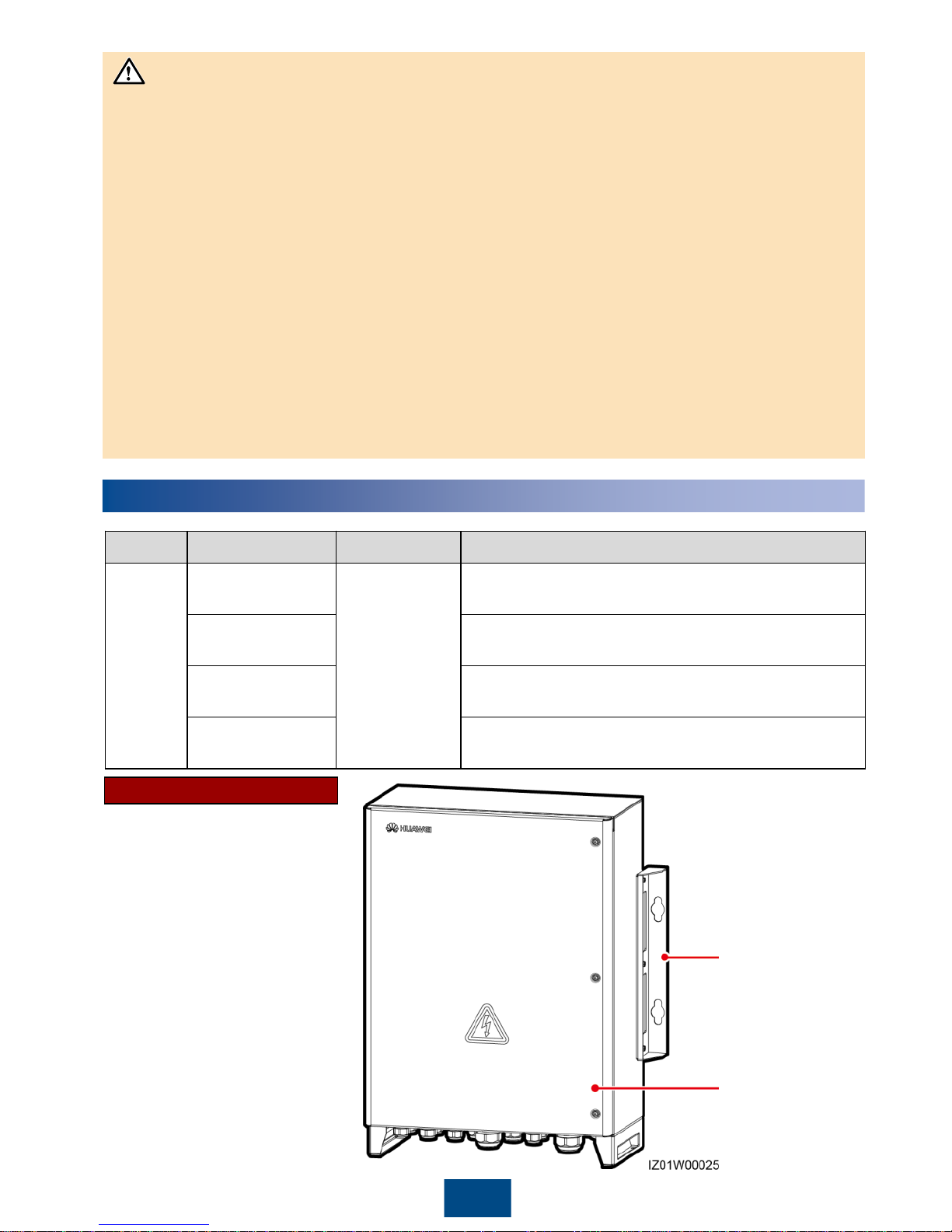
Cabinet Appearance
Name
Model
Voltage Level
Configuration
Smart
array
controller
SmartACU2000B
-
D
-PLC
D: ≤ 800 V
three
-phase
AC input
PLC: supporting the access of one PLC route, no
PID module, no 24 V DC input or output
SmartACU2000B
-
D
-2PLC
2PLC: supporting the access of two PLC routes, no
PID module, no 24 V DC input or output
SmartACU2000B
-
D
-PLC-24V
PLC
-24V: supporting the access of one PLC route,
no PID module, with 24 V DC input and output
SmartACU2000B
-
D
-2PLC-24V
2PLC-24V: supporting the access of two PLC routes,
no PID module, with 24 V DC input and output
NOTICE
Mounting plate
Cabinet door
Page 3
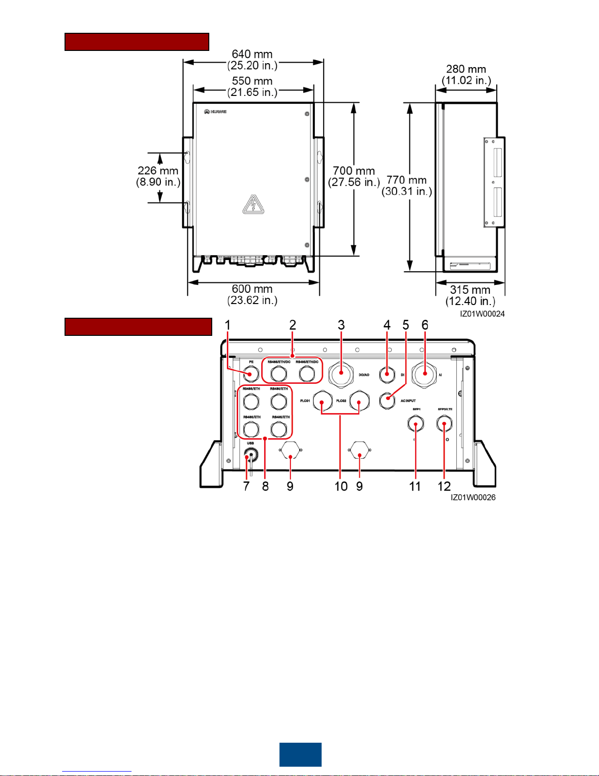
Cabinet Dimensions
2
Port Description
(1)
Protective earthing (PE) cable
waterproof connector (PE, 3/4 in.)
(2) Waterproof connectors for the RS485
communications cable, network cable, and DC input
and output power cables (RS485/ETH/DC, 3/4 in.)
(3) DO/AO signal cable waterproof
connector (DO/AO, 5/4 in.)
(4) DI signal cable waterproof connector (DI, 3/4 in.)
(5) Waterproof connector for the single
phase AC power cable (AC INPUT, 3/4
in.)
(6) AI signal cable waterproof connector (AI, 5/4 in.)
(7)
USB port (USB)
(8)
Waterproof connectors for the RS485
communications cable and network cable
(RS485/ETH, 3/4 in.)
(9) Ventilation valve
(10) Waterproof connectors for the three
-phase AC
power cable (PLC01, PLC02, 1 in.)
(11) Optical cable waterproof connector
(SFP1, 3/4 in.)
(12) Waterproof connector for the optical cable and
network cable (SFP2/LTE, 3/4 in.)
Page 4
3
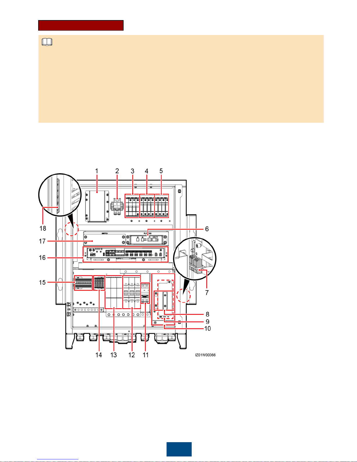
Component Positions
For simplicity purposes, the following figure shows only the components that you need to operate
and reserved installation positions.
Component 1 of the SmartACU2000B-D-PLC is the power adapter. This model does not
include components 2, 5, 6, 12, and 14.
Component 1 of the SmartACU2000B-D-2PLC is the power adapter. This model does not
include components 2 and 14.
Component 1 of the SmartACU2000B-D-PLC-24V is the 24 V DC power module. This model
does not include components 5, 6, and 12.
Component 1 of the SmartACU2000B-D-2PLC-24V is the 24 V DC power module.
(1)
Power adapter or 24 V DC power
module (U01)
(2)
24 V DC input and output switches
(Output: QF06, Input: QF07)
(3)
Single-phase
surge protective device
(SPD) (F03)
(4)
Three-phase SPD 1 (F01)
(5)
Three-phase SPD 2 (F02)
(6) PLC CCO
(7)
Fiber adapter (OFA01 and OFA02)
(8) Position for the power over Ethernet
(POE) SPD
(9) Position for the POE module (POE)
(10) Access terminal box (ATB)
(11) Single
-phase input switch (QF01)
(12) Three-phase input switch 2 (QF04)
(13) Three
-phase input switch 1 (Knife
fuse switch FU01
or circuit breaker
QF02)
(14)
24 V DC input and output
terminals (JX02)
(15)
RS485 communications
terminal (JX01)
(16) SmartLogger2000 (
SmartLogger)
(17) Position for the local area network
(LAN) switch (SWITCH)
(18) PE bar
NOTE
Page 5
4
2
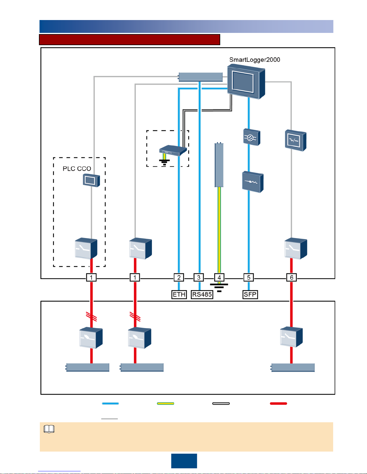
Configurations in Typical Scenarios
Connections inside a
smart array controller
Single-
phase input
switch
Three-
phase input
switch 1
Three-
phase input
switch 2
LAN
switch
PE bar
Power
adapter
RS485 communications
terminal
Fiber
adapter
ATB
Connections
inside a
box-type
transformer
Three-phase
power switch
2
Three-phase
power switch 1
Box-type transformer
busbar 2 A/B/C
Box-type transformer
busbar 1 A/B/C
Station-service power source
L/N (L)
MCB
Fiber Ring Network (no 24 V DC Input or Output)
Components in dashed-line boxes are optional. To highlight the involved area, the figure does not
show all factory-installed components and cables.
Factory-installed
cable:
Site cable:
Signal
cable
Ground
cable
DC power
cable
AC power
cable
NOTE
Page 6
5
2
Connections inside a
smart array controller
Single-
phase
input
switch
Three-
phase
input
switch 1
Three-
phase
input
switch 2
LAN
switch
PE bar
RS485 communications
terminal
Fiber
adapter
ATB
Connections
inside a
box-type
transformer
Three-phase
power switch
2
Three-phase
power switch 1
Box-type transformer
busbar 2 A/B/C
Box-type transformer
busbar 1 A/B/C
Station-service power source
L/N (L)
MCB
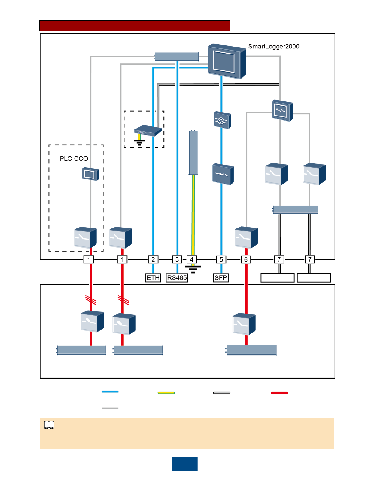
Fiber Ring Network (with 24 V DC Input and Output)
Components in dashed-line boxes are optional. To highlight the involved area, the figure does not
show all factory-installed components and cables.
Factory-installed
cable:
Site cable:
Signal
cable
Ground
cable
DC power
cable
AC power
cable
24 V
DC power
module
24 V DC
output
switch
24 V DC
input and
output
terminals
24 V
DC
input
switch
24 V output 24 V input
NOTE
Page 7
Location Component
Recommended Model or
Specifications
Component
Source
Quantity
Smart array
controller
LAN switch (optional) UT-H605 or ES1000
Can be
purchased
from Huawei
1
Fitting
bag for
optical
ring
switching
Low-speed
optical
module
FTLF1323P1BTR-HW 2
Optical
jumper
PLCLC5S-ST3P302-HW, LC-LCS2-L2, 3ECA1031LCLC002-01-F,
or LP-LP-2S-P-SM-002
8
Box-type
transformer
Miniature circuit
breaker (MCB)
Recommended rated current: 32 A;
number of poles: 2
Prepared by
the customer
1
Threephase
power
switch
Knife fuse
switch
(solution 1)
When the rated AC voltage on
the low-voltage side of the box-
type transformer is less than or
equal to 500 V, the rated voltage
of the knife fuse switch should
be greater than or equal to 500
V.
When the rated AC voltage on
the low-voltage side of the boxtype transformer is greater than
500 V and less than or equal to
800 V, the rated voltage of the
knife fuse switch should be
greater than or equal to 800 V.
Recommended rated current of
the fuse: 32 A; rated current of
the knife fuse switch box ≥ 32 A;
number of poles: 3 (3 fuses for
each knife fuse switch box)
Scenario
with a
doublecolumn
transformer:
1
Scenario
with a dualsplit
transformer:
2
MCCB
(solution 2)
When the rated AC voltage on
the low-voltage side of the boxtype transformer is less than or
equal to 500 V, the rated voltage
of the molded case circuit
breaker (MCCB) should be
greater than or equal to 500 V.
When the rated AC voltage on
the low-voltage side of the box-
type transformer is greater than
500 V and less than or equal to
800 V, the rated voltage of the
MCCB should be greater than or
equal to 800 V.
Let-through energy ≤ 1.26 x 10
6
A2s
Recommended rated current: 32
A; number of poles: 3
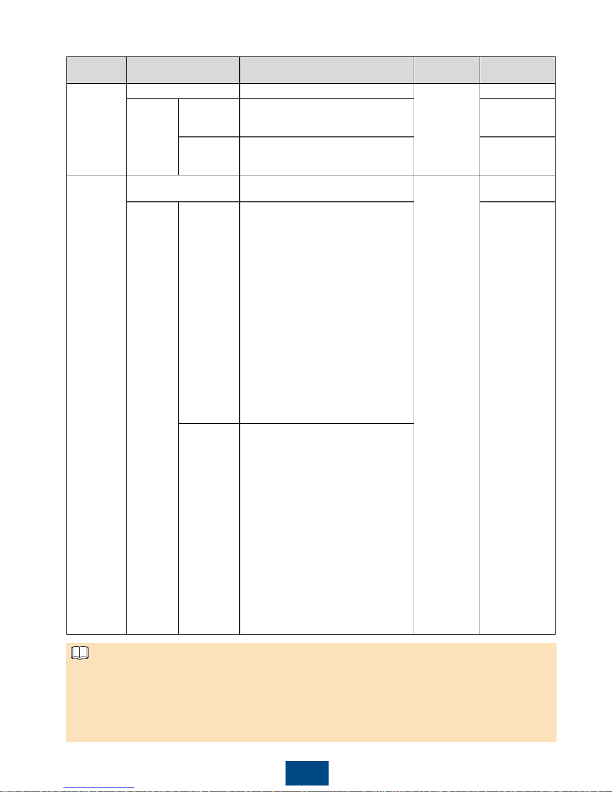
The following table describes the components to be configured in the fiber ring networking scenario.
6
Select either an MCCB or a knife fuse switch as the three-phase power switch. If you select an
MCCB, ensure that the let-through energy of the MCCB meets requirements. The breaking
capacity depends on the limited short-circuit current on the low voltage side of the box-type
transformer.
Models of the components inside the box-type transformer are specified by the box-type
transformer vendor.
NOTE
Page 8
7
No. Cable Recommended Model or Specifications
Cross-sectional Area
Range of the Cable
(Recommended)
1
Three-phase AC
power cable
Three-core (L1, L2, and L3) outdoor copper
armored cable with three OT-M6 terminals (L1,
L2, and L3)
When the rated AC voltage on the low-voltage
side of the box-type transformer is less than or
equal to 500 V, the operating voltage between
the three-phase AC power cable and the
ground should be greater than or equal to 600
V.
When the rated AC voltage on the low-voltage
side of the box-type transformer is greater than
500 V and less than or equal to 800 V, the
operating voltage between the three-phase AC
power cable and the ground should be greater
than or equal to 1000 V.
8–10 mm2(10 mm2)
8 AWG
2
Peripheral
network cable
CAT 5E outdoor shielded network cable with an
outer diameter less than 9 mm (0.35 in.) and
internal resistance not greater than 1.5 ohms/10 m
(1.5 ohms/393.70 in.), as well as a shielded RJ45
connector
N/A
3
Peripheral
RS485
communications
cable
A computer cable (DJYP2VP2-22 2x2x1) or
armored shielded twisted pair that can be used
outdoors and OT-M4 terminals
0.5–1 mm2(1 mm2)
20–18 AWG (18 AWG)
4
Cabinet PE
cable
Outdoor copper cable with an OT-M6 terminal
6–16 mm2(16 mm2)
10–6 AWG (6 AWG)
5 Optical cable
Four-core or eight-core single-mode armored
optical cable with a transmission wavelength of
1310 nm and an outer diameter less than or equal
to 18 mm (0.71 in.)
N/A
6
Single-phase AC
power cable
Common connection: one two-core outdoor
copper armored cable
Connection through a tube: two single-core
outdoor copper cables
Operating voltage to the ground ≥ 300 V
4–6 mm2(4 mm2)
12–10 AWG (12 AWG)
7
24 V DC input
and output
power cables
Common connection: one two-core outdoor
copper armored cable
Connection through a tube: two single-core
outdoor copper cables
Operating voltage to the ground ≥ 300 V
2.5–4 mm2(2.5 mm2)
14–12 AWG (14 AWG)
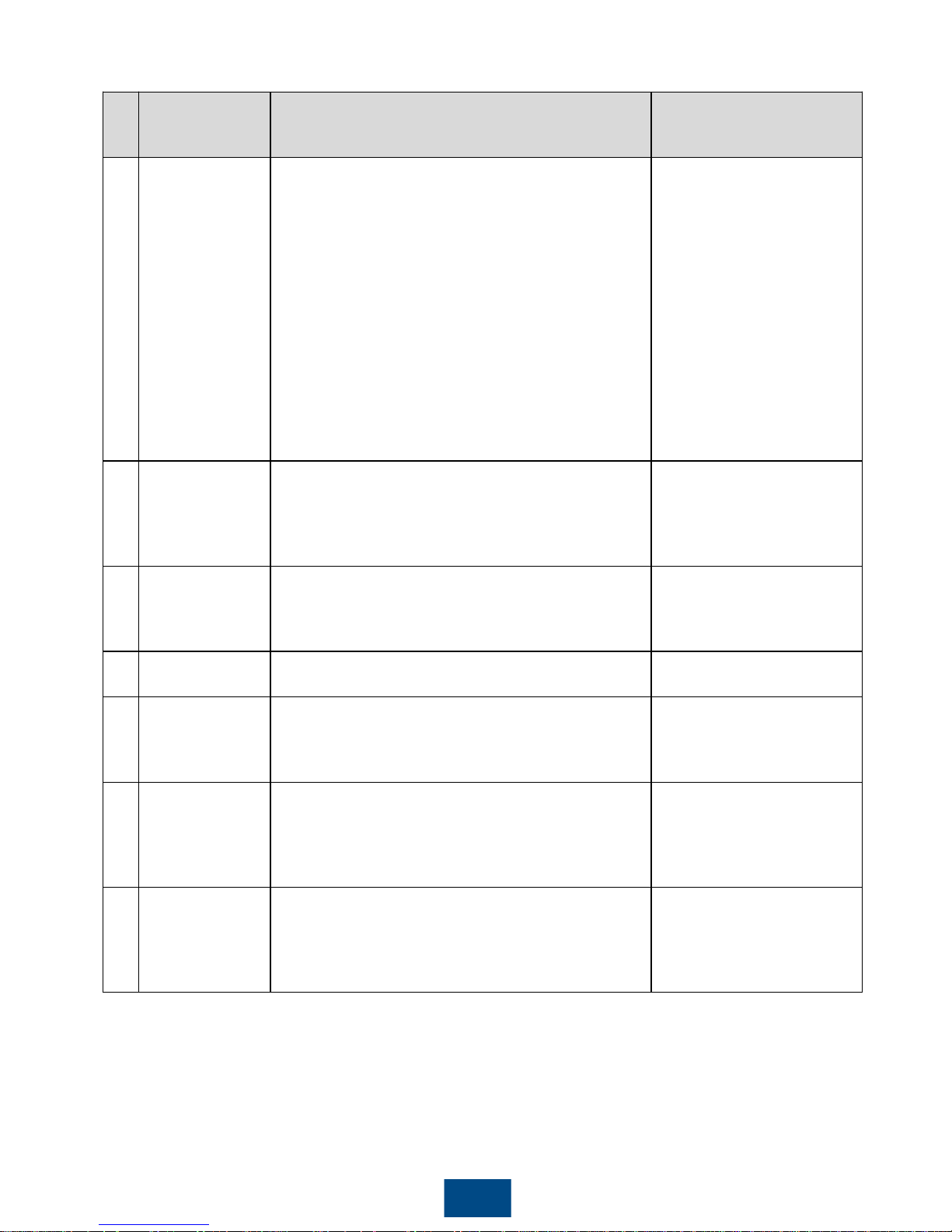
The following table describes the cables to be prepared by yourself in the fiber ring networking scenario.
Page 9
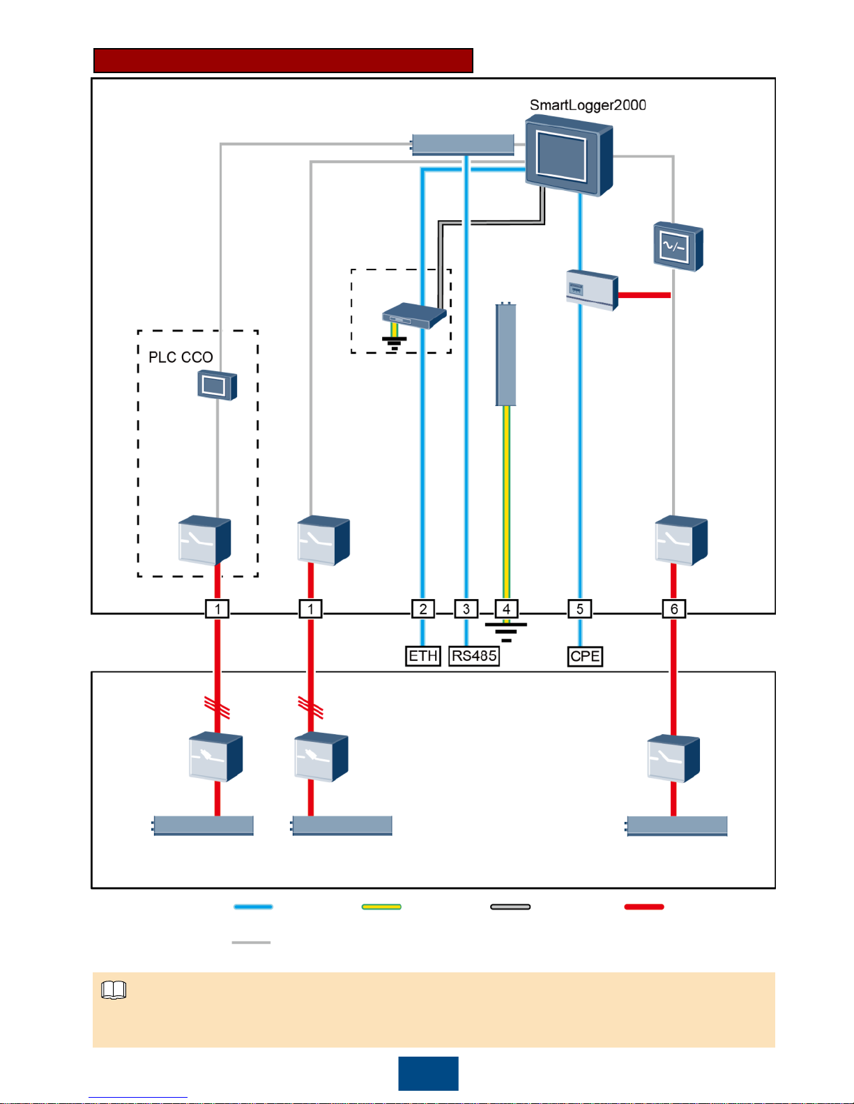
8
Connections inside a
smart array controller
Single-
phase
input
switch
Three-
phase
input
switch 1
Three-
phase
input
switch 2
LAN
switch
PE bar
Power
adapter
RS485 communications
terminal
POE
module
Connections
inside a
box-type
transformer
Three-phase
power switch
2
Three-phase
power switch 1
Box-type transformer
busbar 2 A/B/C
Box-type transformer
busbar 1 A/B/C
Station-service power source
L/N (L)
MCB
Signal
cable
Ground
cable
DC power
cable
AC power
cable
Factory-installed
cable:
Site cable:
4G LTE Network (no 24 V DC Input or Output)
Components in dashed-line boxes are optional. To highlight the involved area, the figure does not
show all factory-installed components and cables.
NOTE
Page 10
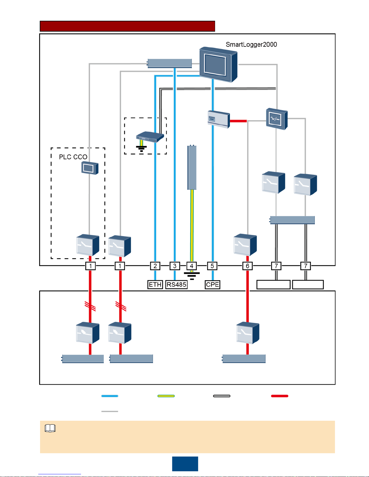
9
Connections inside a
smart array controller
Single-
phase
input
switch
Three-
phase
input
switch 1
Three-
phase
input
switch 2
LAN
switch
PE bar
RS485 communications
terminal
POE
module
Connections
inside a
box-type
transformer
Three-phase
power switch
2
Three-phase
power switch 1
Box-type transformer
busbar 2 A/B/C
Box-type transformer
busbar 1 A/B/C
Station-service power source
L/N (L)
MCB
Signal
cable
Ground
cable
DC power
cable
AC power
cable
Factory-installed
cable:
Site cable:
4G LTE Network (with 24 V DC Input and Output)
Components in dashed-line boxes are optional. To highlight the involved area, the figure does not
show all factory-installed components and cables.
24 V DC
input and
output
terminals
24 V DC
input
switch
24 V
DC power
module
24 V output 24 V input
24 V DC
output
switch
NOTE
Page 11
Location Component
Recommended Model or
Specifications
Component
Source
Quantity
Smart array
controller
LAN switch (optional) UT-H605 or ES1000
Can be
purchased
from Huawei
1
Fitting bags
for the POE
module and
customer-
premises
equipment
(CPE)
POE
module
N/A 1
Outside the
smart array
controller
and boxtype
transformer
CPE N/A 1
Box-type
transformer
MCB
Recommended rated current: 32 A;
number of poles: 2
Prepared by
the customer
1
Threephase
power
switch
Knife fuse
switch
(solution
1)
When the rated AC voltage on
the low-voltage side of the boxtype transformer is less than or
equal to 500 V, the rated voltage
of the knife fuse switch should be
greater than or equal to 500 V.
When the rated AC voltage on
the low-voltage side of the boxtype transformer is greater than
500 V and less than or equal to
800 V, the rated voltage of the
knife fuse switch should be
greater than or equal to 800 V.
Recommended rated current of
the fuse: 32 A; rated current of
the knife fuse switch box ≥ 32 A;
number of poles: 3 (3 fuses for
each knife fuse switch box)
Scenario
with a
doublecolumn
transformer:
1
Scenario
with a dualsplit
transformer:
2
MCCB
(solution
2)
When the rated AC voltage on
the low-voltage side of the boxtype transformer is less than or
equal to 500 V, the rated voltage
of the molded case circuit
breaker (MCCB) should be
greater than or equal to 500 V.
When the rated AC voltage on
the low-voltage side of the boxtype transformer is greater than
500 V and less than or equal to
800 V, the rated voltage of the
MCCB should be greater than or
equal to 800 V.
Let-through energy ≤ 1.26 x 10
6
A2s
Recommended rated current: 32
A; number of poles: 3
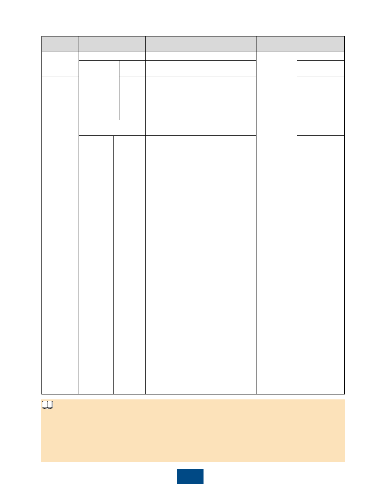
The following table describes the components to be configured in the 4G LTE scenario.
10
Select either an MCCB or a knife fuse switch as the three-phase power switch. If you select an
MCCB, ensure that the let-through energy of the MCCB meets requirements. The breaking
capacity depends on the limited short-circuit current on the low voltage side of the box-type
transformer.
Models of the components inside the box-type transformer are specified by the box-type
transformer vendor.
NOTE
Page 12
11
No. Cable Recommended Model or Specifications
Cross-sectional Area
Range of the Cable
(Recommended)
1
Three-phase AC
power cable
Three-core (L1, L2, and L3) outdoor copper
armored cable with three OT-M6 terminals (L1, L2,
and L3)
When the rated AC voltage on the low-voltage
side of the box-type transformer is less than or
equal to 500 V, the operating voltage between the
three-phase AC power cable and the ground
should be greater than or equal to 600 V.
When the rated AC voltage on the low-voltage
side of the box-type transformer is greater than
500 V and less than or equal to 800 V, the
operating voltage between the three-phase AC
power cable and the ground should be greater
than or equal to 1000 V.
8–10 mm2(10 mm2)
8 AWG
2
Peripheral
network cable
CAT 5E outdoor shielded network cable with an outer
diameter less than 9 mm (0.35 in.) and internal
resistance not greater than 1.5 ohms/10 m (1.5
ohms/393.70 in.), as well as a shielded RJ45
connector
N/A
3
Peripheral
RS485
communications
cable
A computer cable (DJYP2VP2-22 2x2x1) or armored
shielded twisted pair that can be used outdoors and
OT-M4 terminals
0.5–1 mm2(1 mm2)
20–18 AWG (18
AWG)
4
Cabinet PE
cable
Outdoor copper armored cable with an OT-M6
terminal
6–16 mm2(16 mm2)
10–6 AWG (6 AWG)
5
Network cable
from the POE
module to the
CPE
A 20 m (65.62 ft) long network cable delivered with
Huawei CPE (If the length is insufficient, prepare a
cable with the same specifications as a peripheral
network cable.)
N/A
6
Single-phase AC
power cable
Common connection: one two-core outdoor
copper armored cable
Connection through a tube: two single-core
outdoor copper cables
Operating voltage to the ground ≥ 300 V
4–6 mm2(4 mm2)
12–10 AWG (12
AWG)
7
24 V DC input
and output
power cables
Common connection: one two-core outdoor
copper armored cable
Connection through a tube: two single-core
outdoor copper cables
Operating voltage to the ground ≥ 300 V
2.5–4 mm2(2.5 mm2)
14–12 AWG (14
AWG)
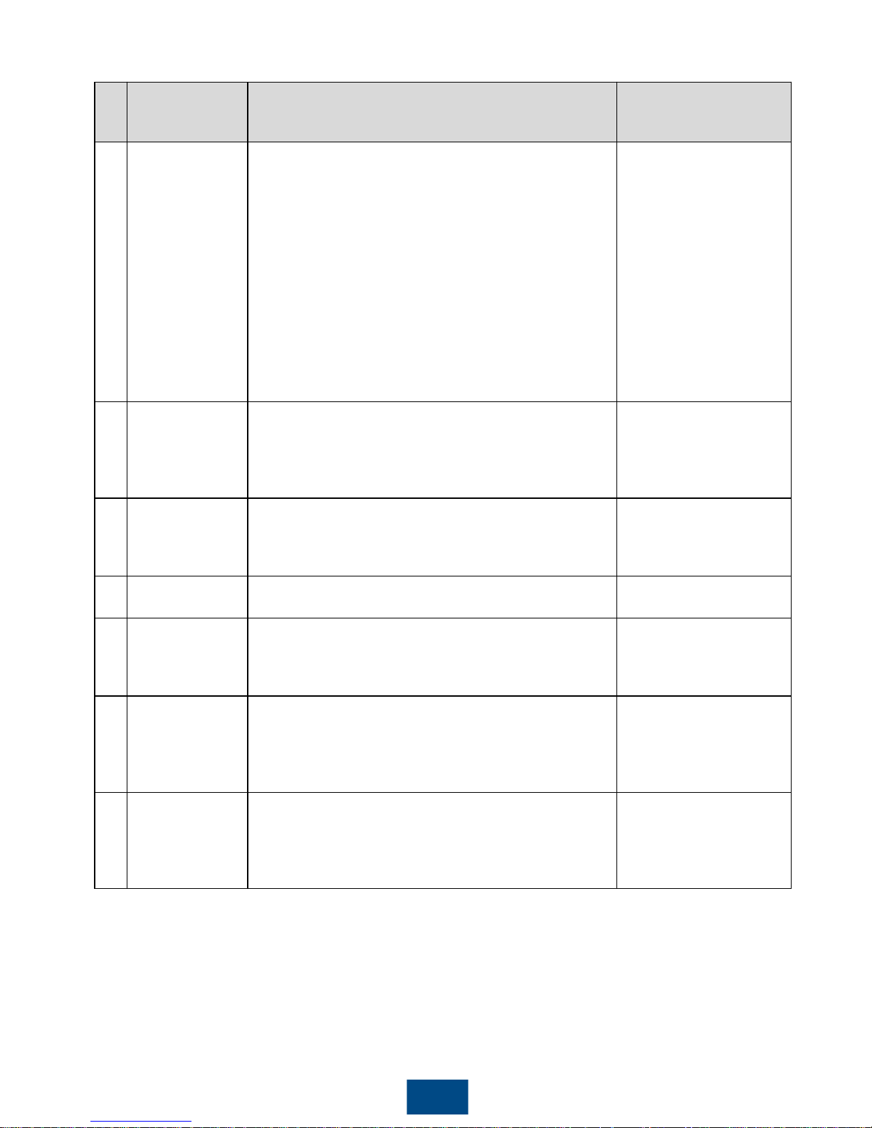
The following table describes the cables to be prepared by yourself in the 4G LTE scenario.
Page 13
12
3
Installing the Cabinet
Preparations
3.1
Securing the Cabinet
3.2
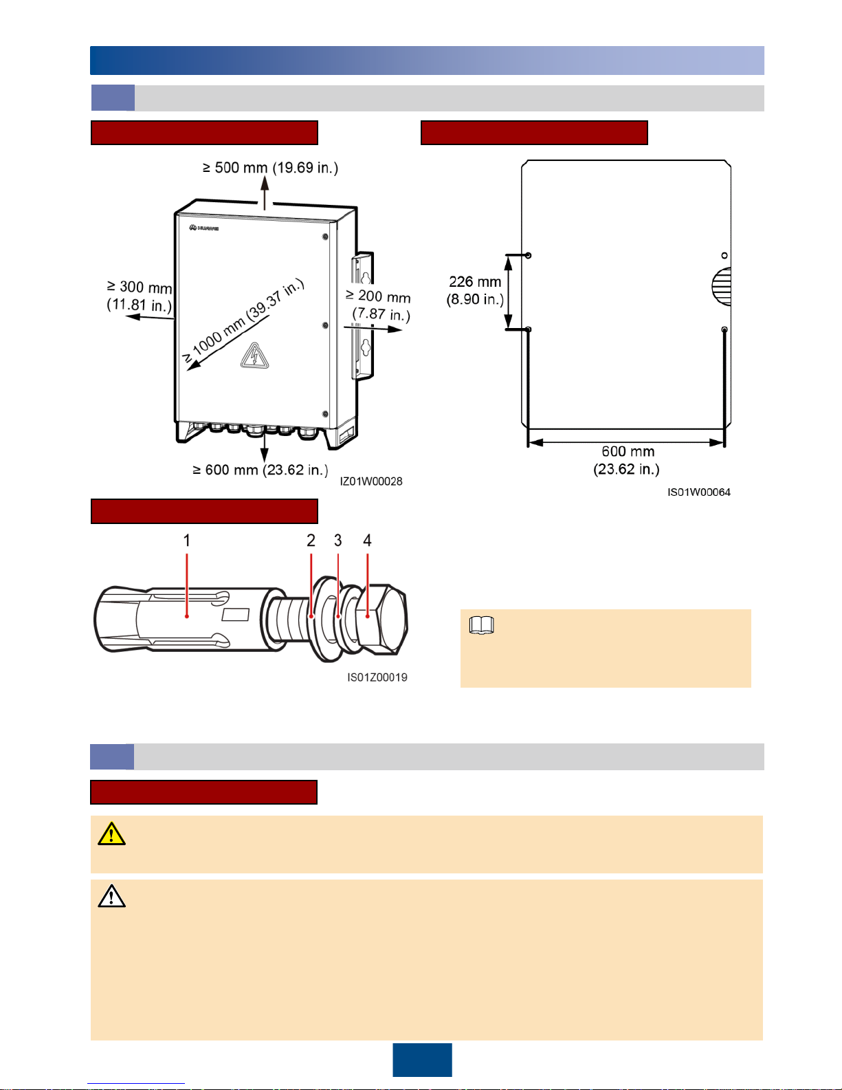
Installation Space Marking-off Template
The marking-off template and expansion
bolts are delivered with the cabinet.
Expansion Bolt
(1) Expansion sleeve
(2) Flat washer
(3) Spring washer
(4) M12x60 bolt
To prevent dust inhalation or contact with eyes, wear safety goggles and an anti-dust mask
when drilling holes.
Clean up any dust in and around the holes using a vacuum cleaner and measure the hole
distances. If the holes are inaccurately positioned, drill holes again.
Level the head of the expansion sleeve with the concrete wall after removing the bolt, spring
washer, and flat washer. Otherwise, the mounting plate will not be securely installed on the
concrete wall.
Avoid drilling holes in the water pipes and power cables buried in the wall.
Wall-mounted Installation
DANGER
NOTE
NOTICE
Page 14
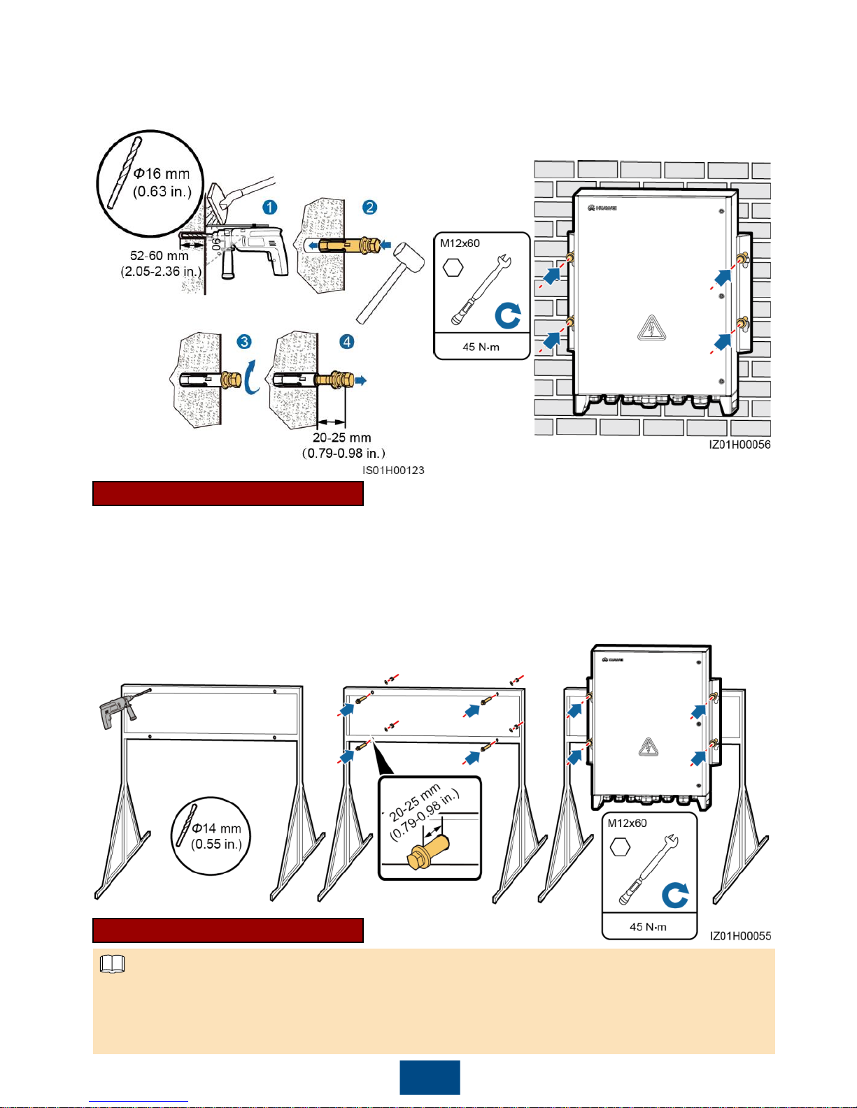
13
3. Secure the cabinet.
1. Determine the hole positions based on the
marking-off template, and then mark the
hole positions using a marker.
2. Install expansion bolts.
1. Determine the hole positions
based on the marking-off
template, and then mark the
hole positions using a marker.
2. Drill holes. (You are advised
to apply anti-rust paint on the
hole positions for protection.)
3. Install bolt assemblies (each
being an expansion bolt with
only a flat washer and a
spring washer).
4. Secure the cabinet.
If you need to pole-mount the smart array controller, prepare a pole mounting bracket based
on the dimensions of the smart array controller. You are advised to use M12 U-shaped bolts to
secure the pole mounting bracket.
The figure is for reference only. The actual pole and pole mounting bracket prevail.
Support-mounted Installation
Pole-mounted Installation
NOTE
Page 15
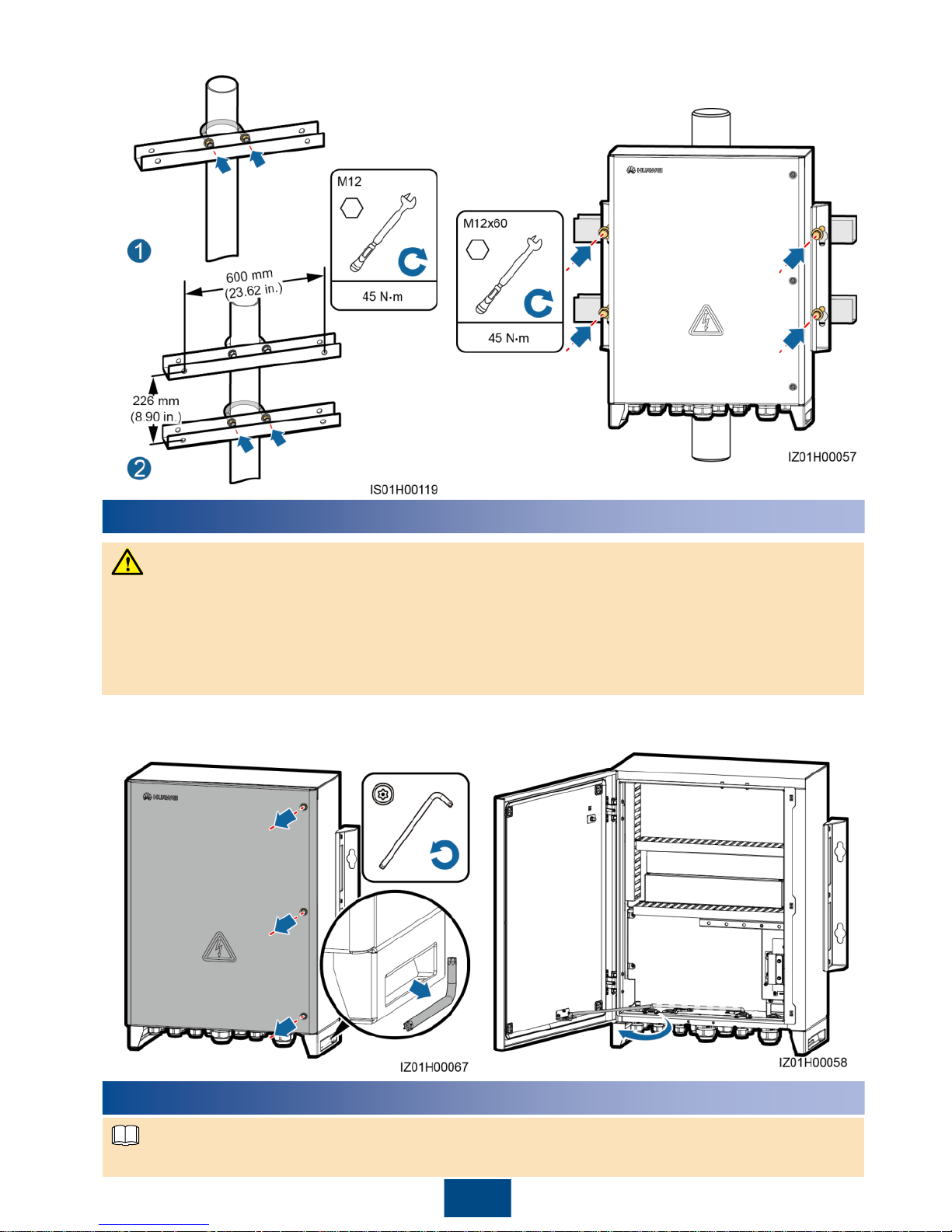
14
1. Remove the security torx wrench bound to
the cabinet base and use the wrench to
loosen security torx screws.
2. Open the cabinet door and install the
support bar.
2. Secure the cabinet. For details, see
"Support-mounted Installation."
1. Secure the pole mounting bracket.
4
Opening the Cabinet Door
Before opening the cabinet door, turn off all upstream switches for the smart array controller to
power off the smart array controller. If you have to operate an energized smart array controller,
wear insulation gloves and take preventive measures.
If you need to open the cabinet door on rainy or snowy days, take protective measures to
prevent rain or snow from entering the cabinet. If it is impossible to take protective measures,
do not open the cabinet door on rainy or snowy days.
Installing Components
Install components based on chapter 2 "Configurations in Typical Scenarios."
5
NOTE
WARNING
Page 16
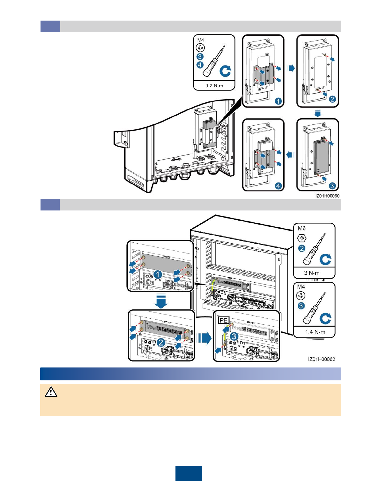
15
1. Loosen screws and remove the mounting
board. Do not remove the screws.
2. Remove screws from the POE module
installation position.
3. Secure the POE module. (The indicators
should be in the lower left corner.)
4. Secure the mounting board.
Installing the POE Module
5.1
1. Remove the panel
from the LAN switch
installation position.
2. Secure the LAN switch.
3. Connect the PE cable
for the LAN switch.
Installing the LAN Switch
5.2
6
Connecting Cables
Connect cables in accordance with the installation laws and regulations of the country or region
where the project is located.
NOTICE
Page 17
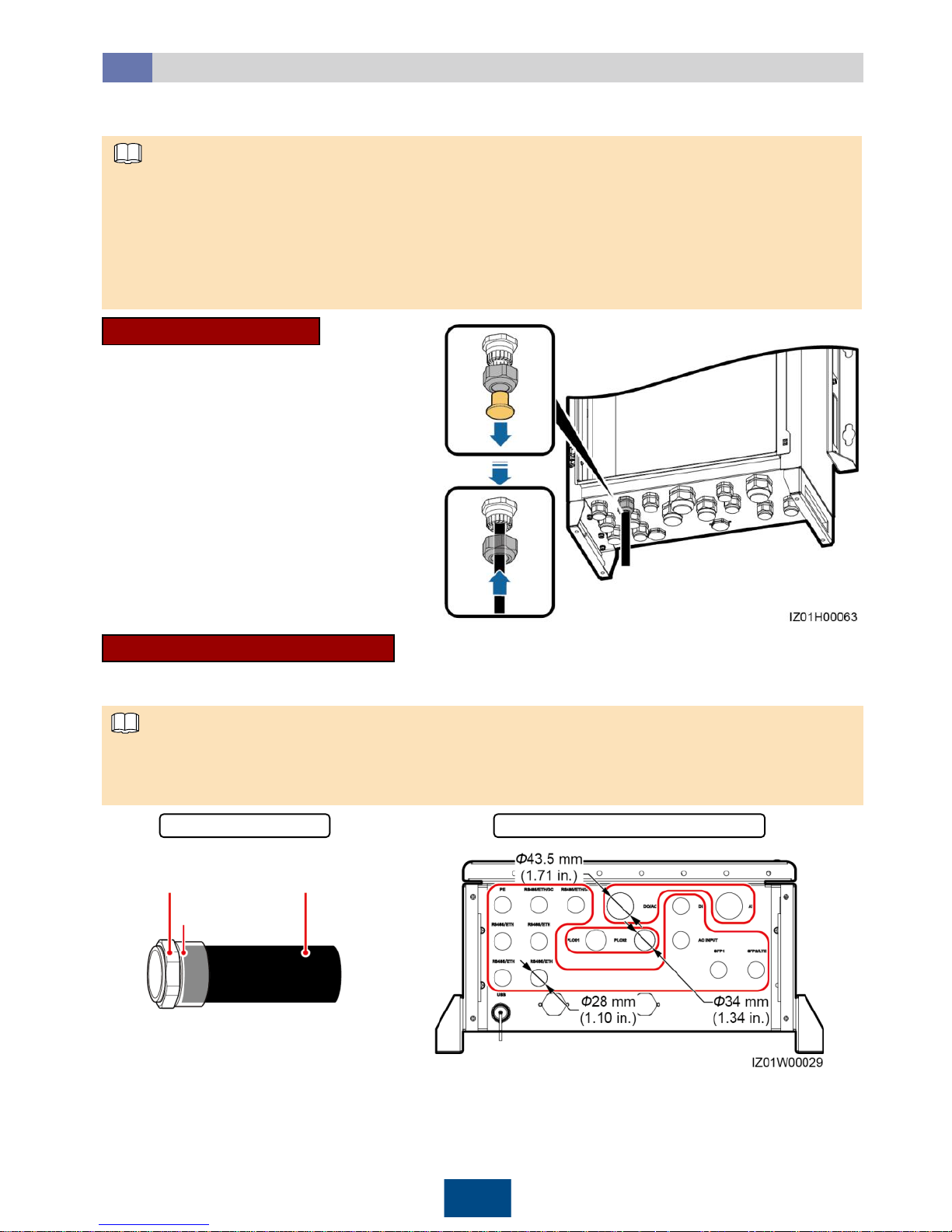
To prevent poor cable connection due to overstress caused by ground subsidence, it is
recommended that the cable be bent and reserved 20–30 mm (0.79–1.18 in.) inside the cabinet
and then connected to the appropriate port.
If a cable has a jacket, ensure that the jacket is in the cabinet.
The following describes how to connect a peripheral cable to the RS485/ETH/DC waterproof
connector in common mode and through a tube, and provides reference for connecting
peripheral cables to other waterproof connectors.
Common Connection
1. Remove the locking cap and plug from
the waterproof connector.
2. Route the cable through the locking
cap and then the waterproof connector.
3. Connect the cable.
4. Tighten the locking cap.
5. Check that the cable is connected
correctly and securely. Seal the
waterproof connector and cable hole
using the supplied firestop putty.
6. Clear foreign matter from the cabinet.
If you choose common connection, ensure
that the appropriate cable is available.
16
NOTE
Connection Through a Tube
If you choose connection through a tube, ensure that the appropriate cable and tube are available.
Prepare appropriate tubes based on the diameters of bottom cable holes. It is recommended that
the tube specifications comply with the waterproof connector specifications. For example, for a 3/4
in. waterproof connector, a 3/4 in. tube is recommended.
Nut Conduit
Diameters of bottom cable holesTube
Fitting
NOTE
Selecting a Connection Method
6.1
You can connect a peripheral cable to the smart array controller in common mode or through a
tube based on site requirements.
Page 18
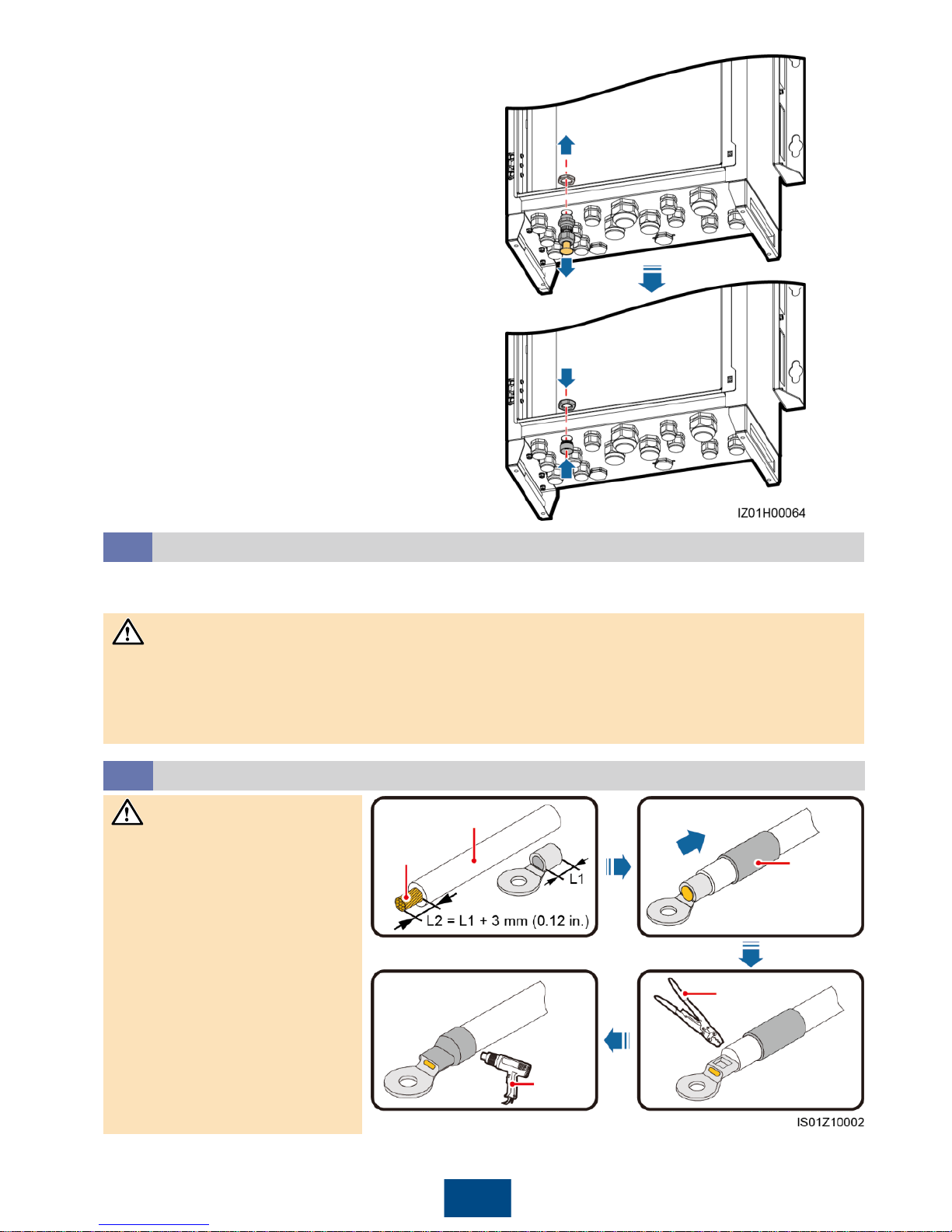
17
1. Remove the locking cap and plug from the
waterproof connector, and then remove the
waterproof connector.
2. Secure the tube fitting using the nut
delivered with the tube.
3. Route the cable through the tube conduit
and then fitting.
4. Connect the cable.
5. Secure the fitting to the conduit.
6. Check that the cable is connected correctly
and securely. Then take appropriate
measures to ensure that the tube conduit
and fitting are secured reliably, and seal the
cable hole using supplied firestop putty.
7. Clear foreign matter from the cabinet.
You can connect a peripheral cable to the smart array controller in common mode or through a tube.
The way of handling the bottom waterproof connector varies depending on the connection
method. For details, see section 6.1 "Selecting a Connection Method."
Cables to the cabinet interior are connected in the same way irrespective of which connection
method is used. The following uses common connection as an example.
Preparing Cables
6.2
Before connecting cables, prepare appropriate cables by referring to chapter 2 "Configurations in
Typical Scenarios."
NOTICE
Core wire
Insulation layer
Heat
shrink
tubing
Crimping
tool
Heat gun
Crimping an OT Terminal
6.3
Avoid scratching the core
wire when stripping a cable.
The cavity formed after the
conductor crimp strip of the
OT terminal is crimped must
wrap the core wires
completely. The core wires
must contact the OT
terminal closely.
Wrap the wire crimping area
with heat shrink tubing or
PVC insulation tape. The
right figure uses heat shrink
tubing as an example.
When using the heat gun,
protect devices from being
scorched.
NOTICE
Page 19
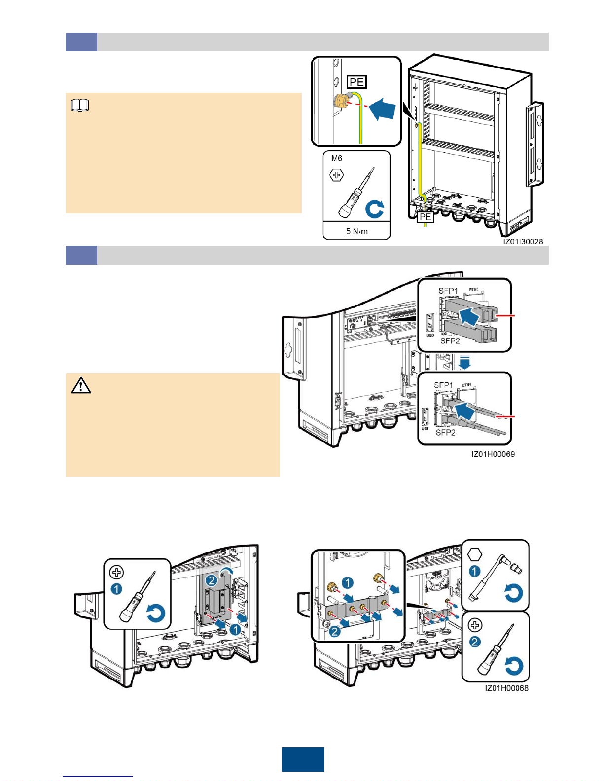
18
Connecting the PE Cable
6.4
1. Crimp an OT terminal.
2. Secure the PE cable.
Connect the PE cable to the nearest
ground point or the ground bar in the boxtype transformer.
To enhance the corrosion resistance of a
ground terminal, you are advised to apply
silica gel or paint on it after connecting the
ground cable.
Connecting Communications Cables for the Fiber Ring Network
6.5
Prepare the fitting bag for optical ring
switching which contains the low-speed
optical module and optical jumper.
1. Insert the low-speed optical modules
respectively into the SFP1 and SFP2
ports of the SmartLogger until they snap
into place. Then pull the modules back to
ensure that they are connected securely.
2. Connect factory-installed optical jumpers
to the low-speed optical modules.
Low-
speed
optical
module
Optical
jumper
Pay attention to the directions of the lowspeed optical modules. The label of the
low-speed optical module on the SFP1
port faces upwards, whereas the label of
the low-speed optical module on the
SFP2 port faces downwards.
NOTE
NOTICE
3. Remove the ATB cover. 4. Remove the optical cable fastener.
Page 20
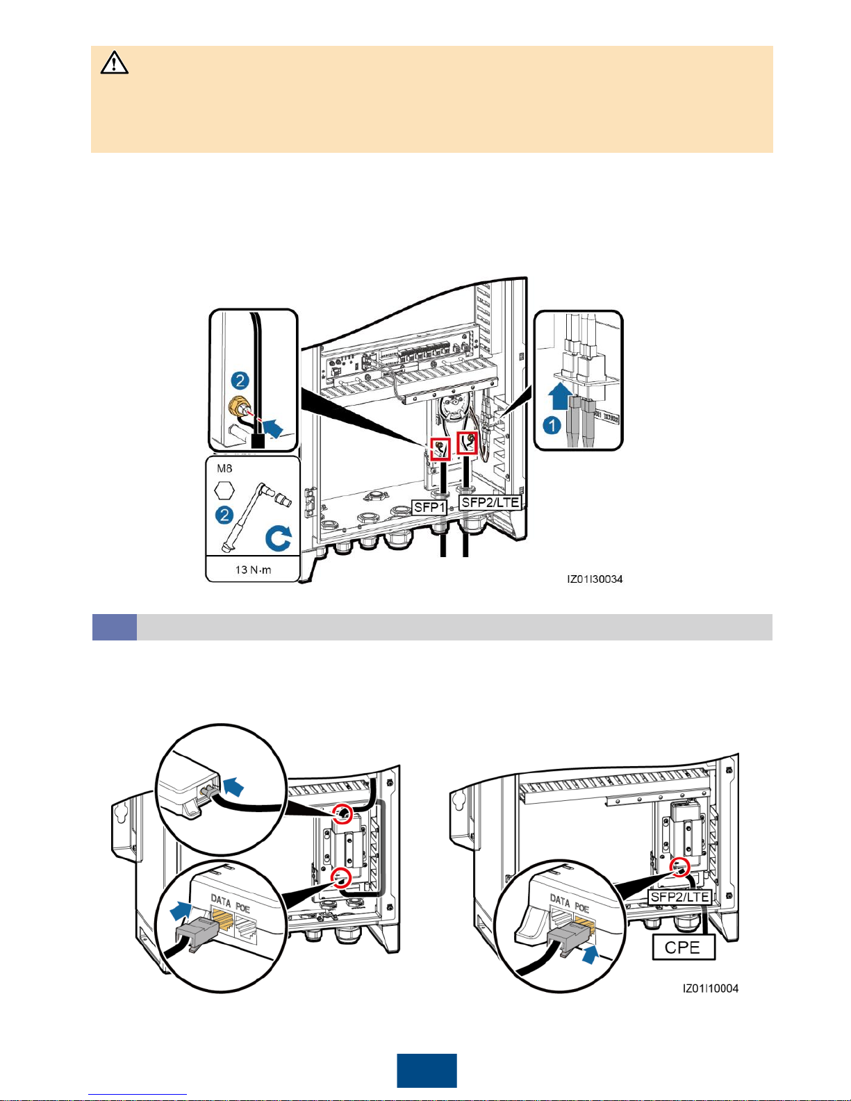
19
Connect two optical cables in a ring optical network, and connect one optical cable in a star
optical network.
As optical cables are hard, prepare optical cables before routing them into the cabinet.
Only professionals are allowed to connect optical cables.
5. Connect one end of the optical jumper to the fiber adapter.
6. Route the other end of the optical jumper through the cable hole on the side of the ATB, and
then connect the cable to the ATB.
7. Connect the peripheral optical cable to the ATB, splice the optical cable and the optical jumper,
and then wind the spliced cable around the fiber spool on the ATB.
8. Check that the cables are connected correctly and securely. Then reinstall the optical cable
fastener and ATB cover.
NOTICE
Connecting the 4G LTE Cable
6.6
1. Connect the factory-installed network cable
to the DATA port on the POE module, and
the factory-installed power cable to the POE
module.
2. Connect the CPE network cable to the POE
port on the POE module.
Page 21
Box-type
transformer
busbar 1
A/B/C
Box-type
transformer
busbar 2
A/B/C
Three-phase
power switch 1
Three-phase
power switch 2
Connecting the Three-Phase AC Power Cable (a Circuit Breaker as the
Three-Phase Input Switch)
6.7
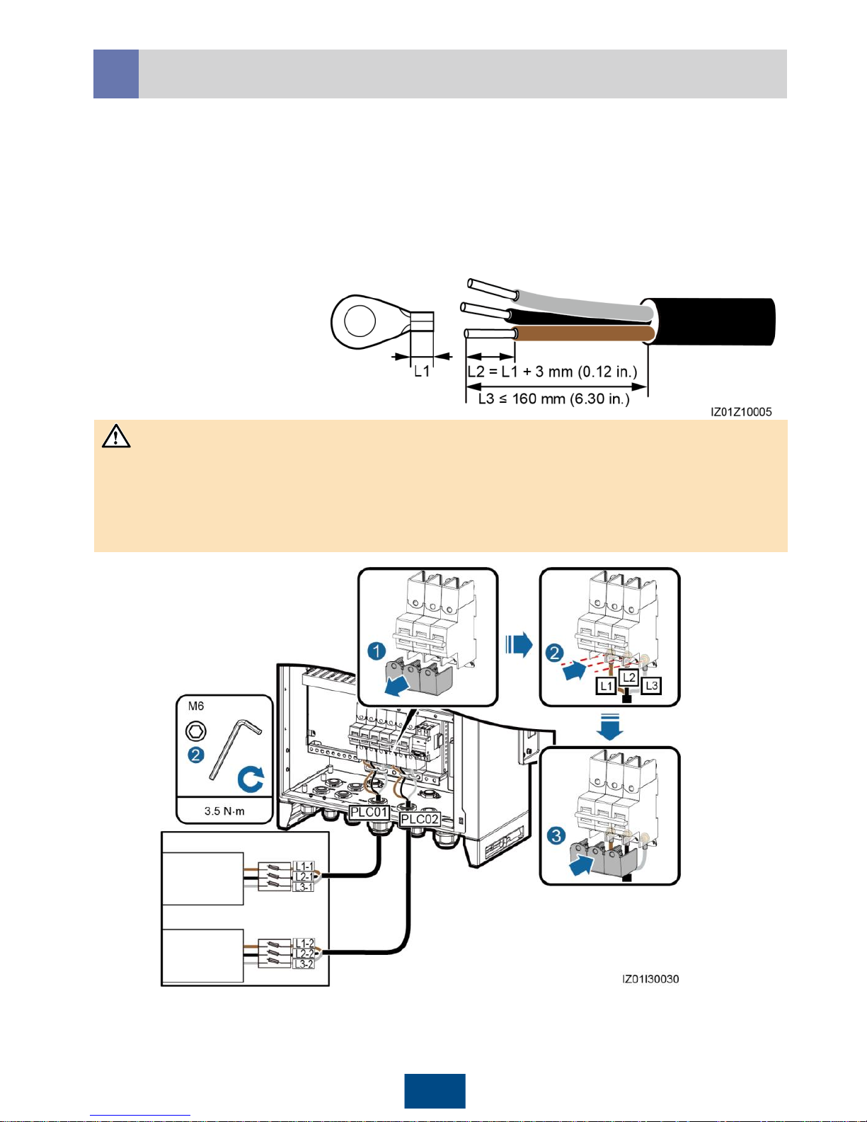
For the smart array controller that supports the access of one PLC route, connect the threephase AC power cable to the QF02 switch.
For the smart array controller that supports the access of two PLC routes, connect the first route
of three-phase AC power cable to the QF02 switch, and the second route of three-phase AC
power cable to the QF04 switch.
This section describes how to connect the three-phase AC power cable for the smart array
controller that supports the access of two PLC routes. For details about how to connect the
three-phase AC power cable for the smart array controller that supports the access of one PLC
route, refer to the way of connecting the first route of three-phase AC power cable.
1. Prepare a cable.
2. Crimp an OT terminal.
3. Connect the L1, L2, and L3
cables to the three-phase
input switch.
4. Bind the cable.
20
Connect the L1-1, L2-1, and L3-1 cables from the QF02 switch respectively to ports A, B, and C
on the box-type transformer busbar 1 over a three-phase power switch.
Connect the L1-2, L2-2, and L3-2 cables from the QF04 switch respectively to ports A, B, and C
on the box-type transformer busbar 2 over a three-phase power switch.
Ensure that the L1, L2, and L3 cables are connected in correct phase sequence.
NOTICE
Box-type
transformer
Page 22
Connecting the Three-Phase AC Power Cable (a Knife Fuse Switch as
the Three-Phase Input Switch)
6.8
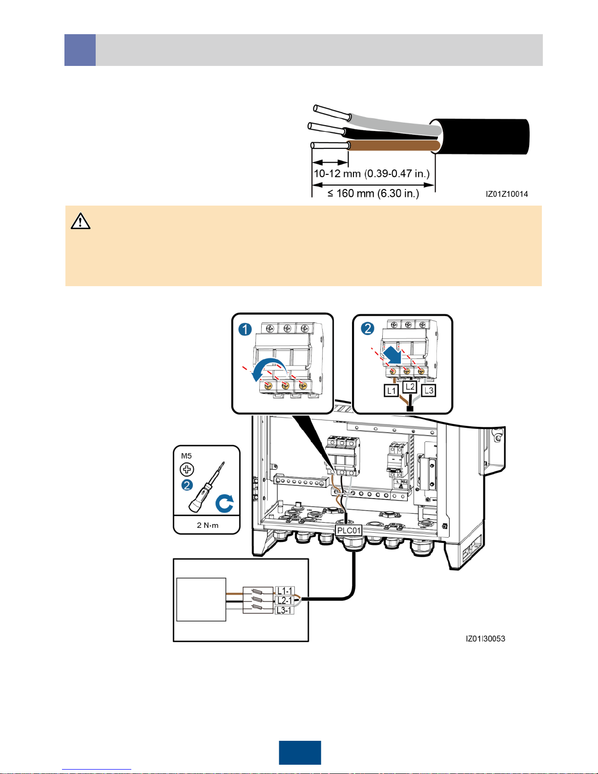
21
1. Prepare a cable.
2. Connect the L1, L2, and L3
cables to the three-phase input
switch.
3. Bind the cable.
For the smart array controller that supports the access of one PLC route, connect the three-phase
AC power cable to the FU01 switch.
• Connect the L1-1, L2-1, and L3-1 cables from the FU01 switch respectively to ports A, B, and C
on the box-type transformer busbar 1 over a three-phase power switch.
• Ensure that the L1, L2, and L3 cables are connected in correct phase sequence.
Box-type
transformer
busbar 1
A/B/C
Three-phase
power switch 1
NOTICE
Box-type transformer
Page 23
Connecting the Peripheral RS485 Communications Cable
6.9
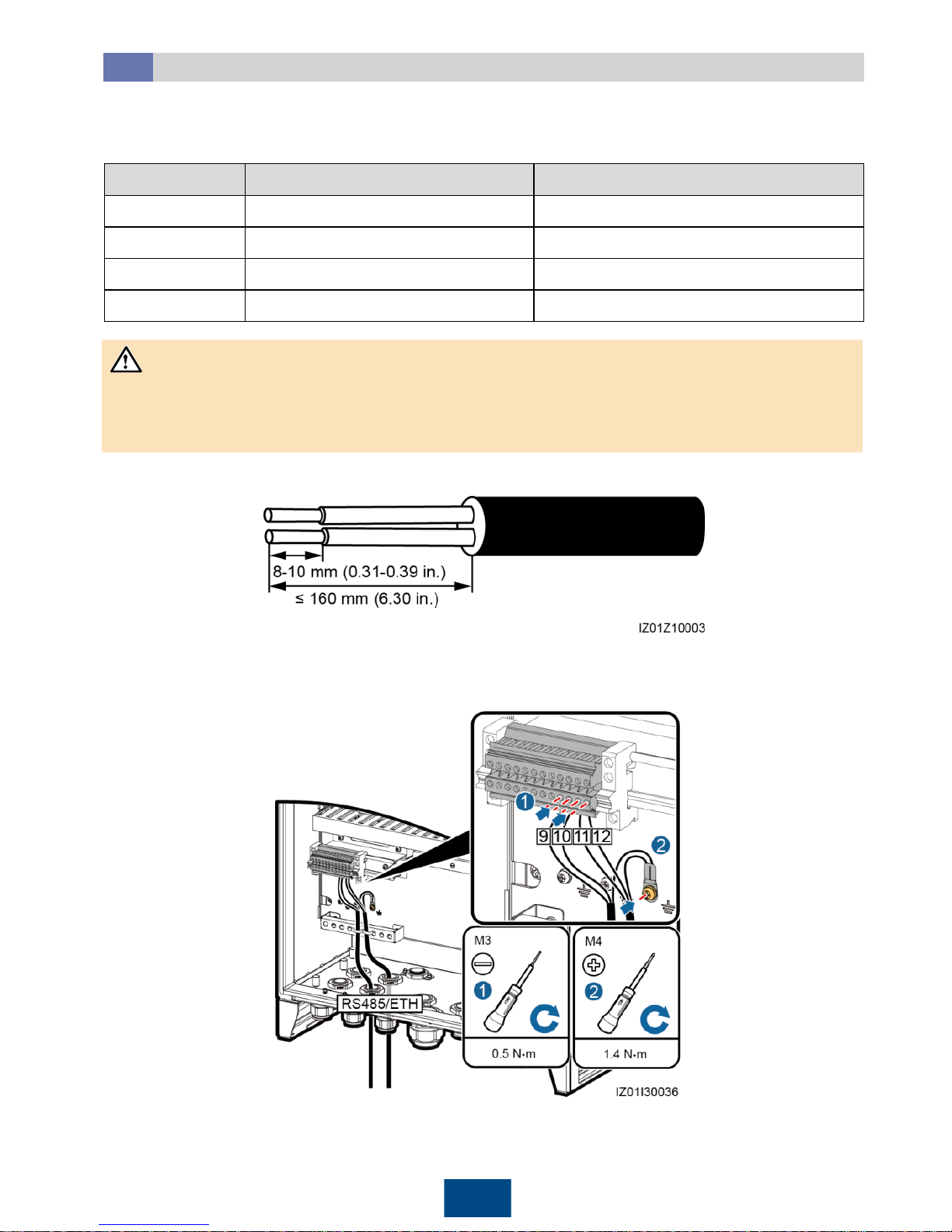
No. Port on the JX01 Terminal Block Definition
9 RS485-5 (+) RS485A, RS485 differential signal+
10 RS485-5 (–) RS485B, RS485 differential signal–
11 RS485-6 (+) RS485A, RS485 differential signal+
12 RS485-6 (–) RS485B, RS485 differential signal–
Connect peripheral RS485 communications cables to JX01. All RS485 communications cables are
connected in the same way. This section describes how to connect two RS485 communications
cables.
For the smart array controller that supports the access of two PLC routes, do not connect a
peripheral RS485 communications cable to the RS485-2 port (ports 3 and 4 on the JX01), because
the PLC CCO module communications cable has connected to this port.
2. Connect the communications cable to the JX01 terminal block.
3. Crimp an OT terminal for the shield layer and connect the shield layer to the ground point in the
cabinet.
4. Bind the communications cable.
1. Prepare a communications cable.
22
NOTICE
Page 24
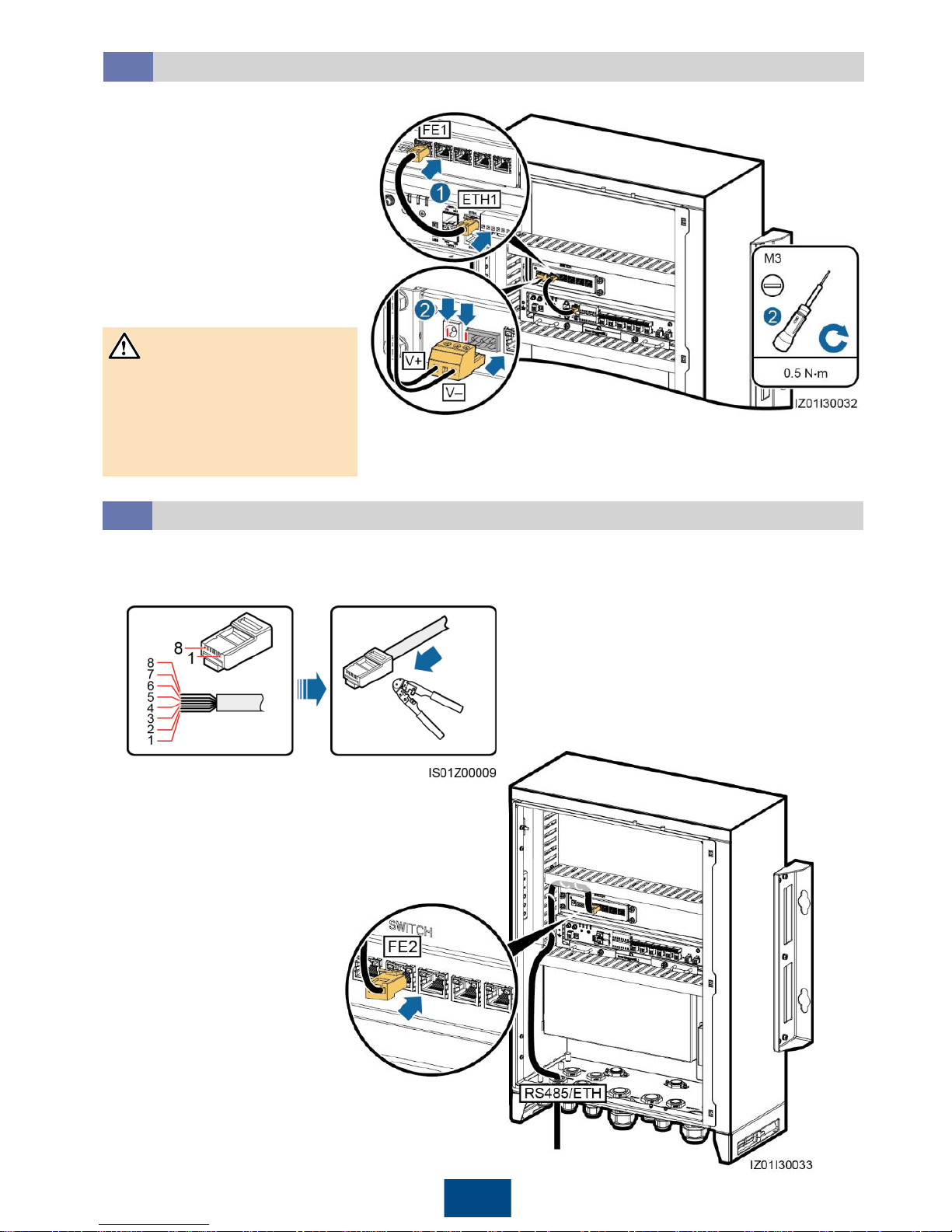
1. Prepare a network cable.
2. Verify that the network cable
functions properly using a
network cable tester.
3. Connect the peripheral
network cable to the FE2
port on the LAN switch.
4. Bind the network cable.
Connect peripheral network cables to ports FE2–FE5 on the LAN switch. All network cables are
connected in the same way. This section describes how to connect one network cable.
(1) White
-and-orange
(2) Orange
(3) White
-and-green
(4) Blue
(5) White
-and-blue
(6) Green
(7) White
-and-brown
(8) Brown
6.11
Connecting the Peripheral Network Cable
1. Connect the FE1 port on
the LAN switch to the ETH1
port on the SmartLogger
using the network cable
delivered with the LAN
switch.
2. Connect the factoryinstalled power cable to the
LAN switch using the wiring
terminal delivered with the
LAN switch.
Connect the SWITCH-12V+
cable to the V+ power port on
the LAN switch, and the
SWITCH-12V– cable to the V–
power port on the LAN switch.
23
NOTICE
Connecting the LAN Switch Cable
6.10
Page 25
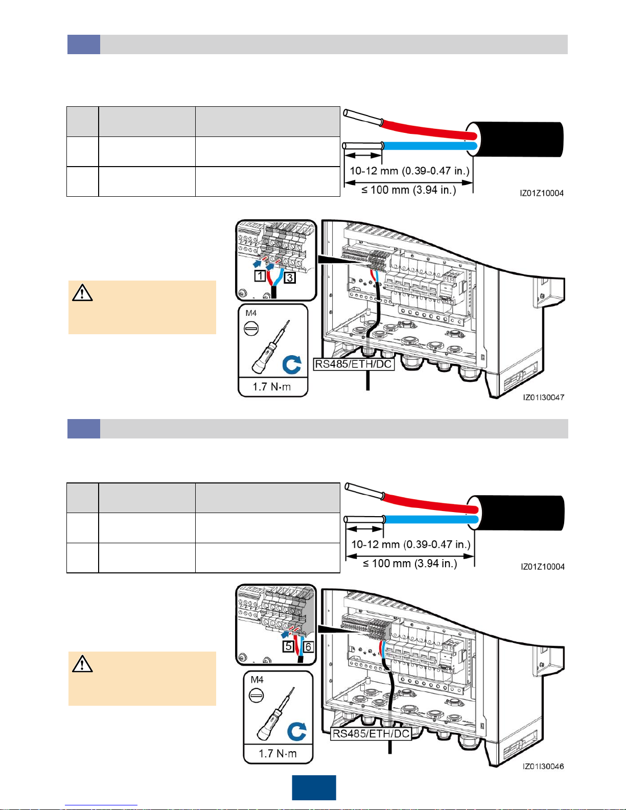
24
1. Prepare a cable.
2. Connect the 24 V DC
output power cable to
the JX02 terminal block.
3. Bind the cable.
Do not connect the cable
reversely.
6.12
Connecting the 24 V DC Output Power Cable
6.13
Connecting the 24 V DC Input Power Cable
1. Prepare a cable.
2. Connect the 24 V DC
input power cable to the
JX02 terminal block.
3. Bind the cable.
Do not connect the cable
reversely.
You can connect one or two 24 V DC output power cables to the smart array controller that
supports 24 V DC input and output. DC output power cables are connected in the same manner.
This section describes how to connect one route of DC output power cable.
NOTICE
No.
Port on the JX02
Terminal Block
Definition
1, 2
24VOUT+
Positive terminal of the 24
V DC output power cable
3, 4
24VOUT
–
Negative terminal of the 24
V DC output power cable
No.
Port on the JX02
Terminal Block
Definition
5 24VIN+
Positive terminal of the 24
V DC input power cable
6 24VIN–
Negative terminal of the 24
V DC input power cable
You can connect one 24 V DC input power cable to the smart array controller that supports 24 V
DC input and output.
NOTICE
Page 26
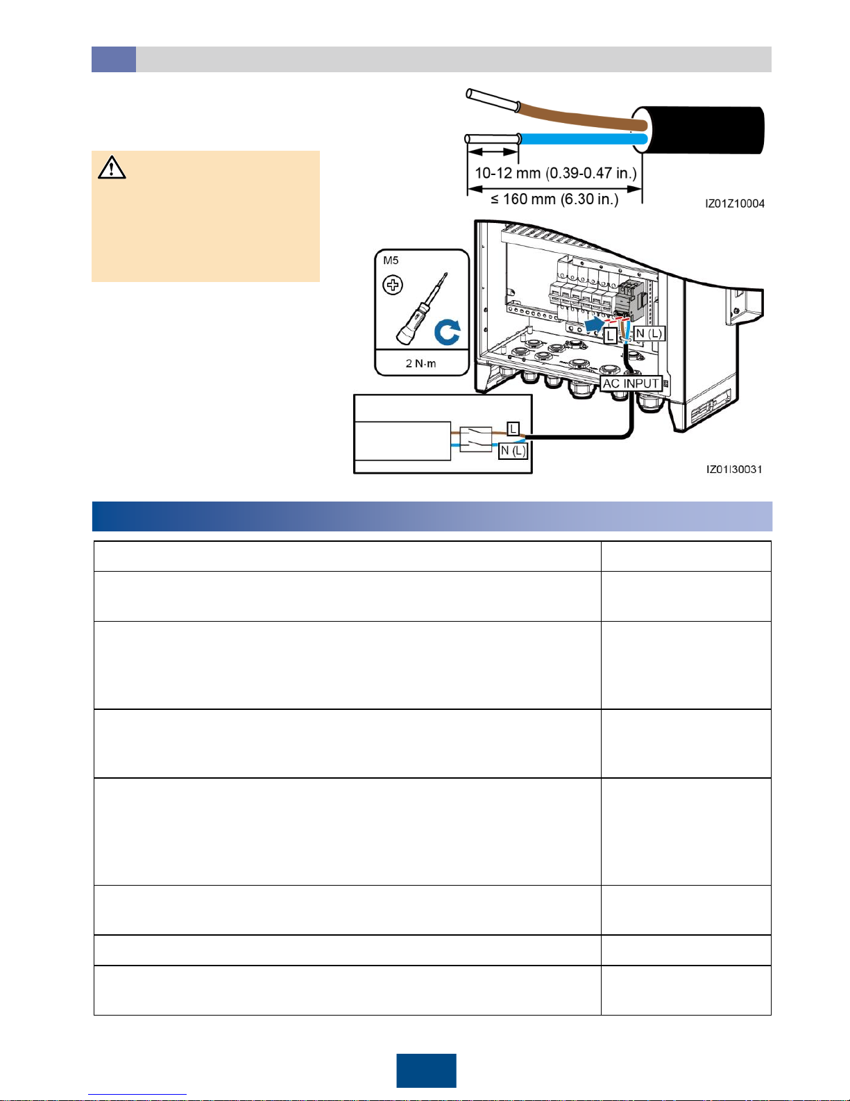
25
1. Prepare a cable.
2. Connect the cable to the
single-phase input switch.
3. Bind the cable.
Box-type transformer
Station-service
power source
L/N (L)
MCB
6.14
Connecting the Single-Phase AC Power Cable
Connect the L and N (L) cables
to the L and N (L) terminals of
the station-service power
source for the box-type
transformer through an MCB.
7
Verifying the Installation
1.
The cabinet and all components are installed properly.
Yes
□No□
N/A
□
2. All upstream switches for the cabinet and all switches inside the cabinet
are OFF.
Yes
□No□
N/A
□
3. All cables are connected correctly and securely, without exposed metal.
Cables are bound neatly, and cable ties are secured evenly and
properly in the same direction. Extra parts of cable ties are neatly cut.
There is no unnecessary adhesive tape or cable tie on cables.
Yes
□No□
N/A
□
4.
Routing for power cables and signal cables meets the requirements for
routing strong-current and weak-current cables and complies with the
cable routing plan.
Yes
□No□
N/A
□
5.
The locking caps on all waterproof connectors in use at the bottom of
the cabinet are tightened, or the tubes (if used) are secured to the
cabinet. All waterproof connectors or tubes in use are applied with
firestop putty. Idle cable holes at the bottom of the cabinet are plugged
and the locking caps are tightened.
Yes
□No□
N/A
□
6.
The cover on the USB port is tightened, and the USB cable inside the
cabinet is secure.
Yes
□No□
N/A
□
7.
The cabinet interior is clean, without dust, dirt, or foreign matter.
Yes
□No□
N/A
□
8.
The paint on the cabinet exterior is intact. Repaint immediately the part
where paint has fallen off to prevent corrosion.
Yes
□No□
N/A
□
NOTICE
Page 27
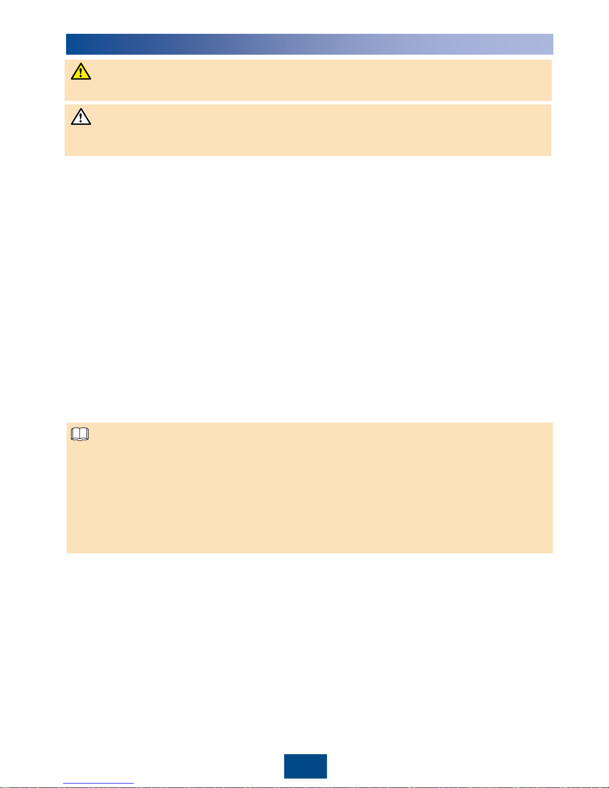
26
8
Powering On the System
1. Turn on the single-phase power switch that controls the power supply from the remote box-type
transformer to the smart array controller.
2. Turn on the three-phase power switch that controls the power supply from the remote box-type
transformer to the smart array controller.
If the smart array controller supports the access of one PLC route, turn on one three-phase
power switch.
If the smart array controller supports the access of two PLC routes, turn on two three-phase
power switches.
3. Check that the input voltages of all switches of the smart array controller are within appropriate
operating voltage ranges using a multimeter.
4. Turn on the QF01 single-phase input switch on the smart array controller.
5. Turn on the DC input and output switches on the smart array controller.
If 24 V DC input and output are not used, skip this step.
If 24 V DC input is used, turn on the QF07 DC input switch.
If 24 V DC output is used, turn on the QF06 DC output switch.
6. Turn on the three-phase input switch on the smart array controller.
If the smart array controller supports the access of one PLC route, turn on the QF02 (or FU01)
three-phase input switch.
If the smart array controller supports the access of two PLC routes, turn on the QF02 and
QF04 three-phase input switches.
Ensure that the power voltage of the smart array controller is within the operating voltage range,
and the three-phase input voltage is within the PLC module operating voltage range.
Put on insulation gloves before powering on the system.
For details about the status of the energized SmartLogger2000 and PLC CCO as well as the
commissioning procedure, see the SmartLogger2000 User Manual. When the smart array
controller communicates with the inverter over PLC, log in to the embedded WebUI of the
SmartLogger2000, choose Monitoring > PLC > Networking Settings, and set Networking to
Enable (default value). When the smart array controller communicates with the inverter only
over RS485, set Networking to Disable. (The WebUI screenshots for SmartLogger
V200R001C30SPC106 are used as an example.)
The LAN switch can be directly put into use without commissioning after power-on.
NOTICE
NOTE
DANGER
Page 28
27
10
FAQ
10.1
How Should I Power Off the System Before Maintenance?
Put on insulation gloves before powering off the system.
10.2
How Should I Determine an Unavailable Single-/Three-Phase SPD?
If an SPD is damaged or its indication window is red, the SPD is deemed unavailable.
1. Turn off the single-phase power switch that controls the power supply from the remote box-type
transformer to the smart array controller.
2. Turn off the three-phase power switch that controls the power supply from the remote box-type
transformer to the smart array controller.
If the smart array controller supports the access of one PLC route, turn off one three-phase
power switch.
If the smart array controller supports the access of two PLC routes, turn off two three-phase
power switches.
3. Turn off the DC input and output switches on the smart array controller.
If the smart array controller does not support 24 V DC input or output, skip this step.
If the smart array controller supports 24 V DC input and output, turn off the QF06 DC output
switch and QF07 DC input switch.
4. Turn off the QF01 single-phase input switch on the smart array controller.
5. Turn off the three-phase input switch on the smart array controller.
If the smart array controller supports the access of one PLC route, turn off the QF02 (or FU01)
three-phase input switch.
If the smart array controller supports the access of two PLC routes, turn off the QF02 and
QF04 three-phase input switches.
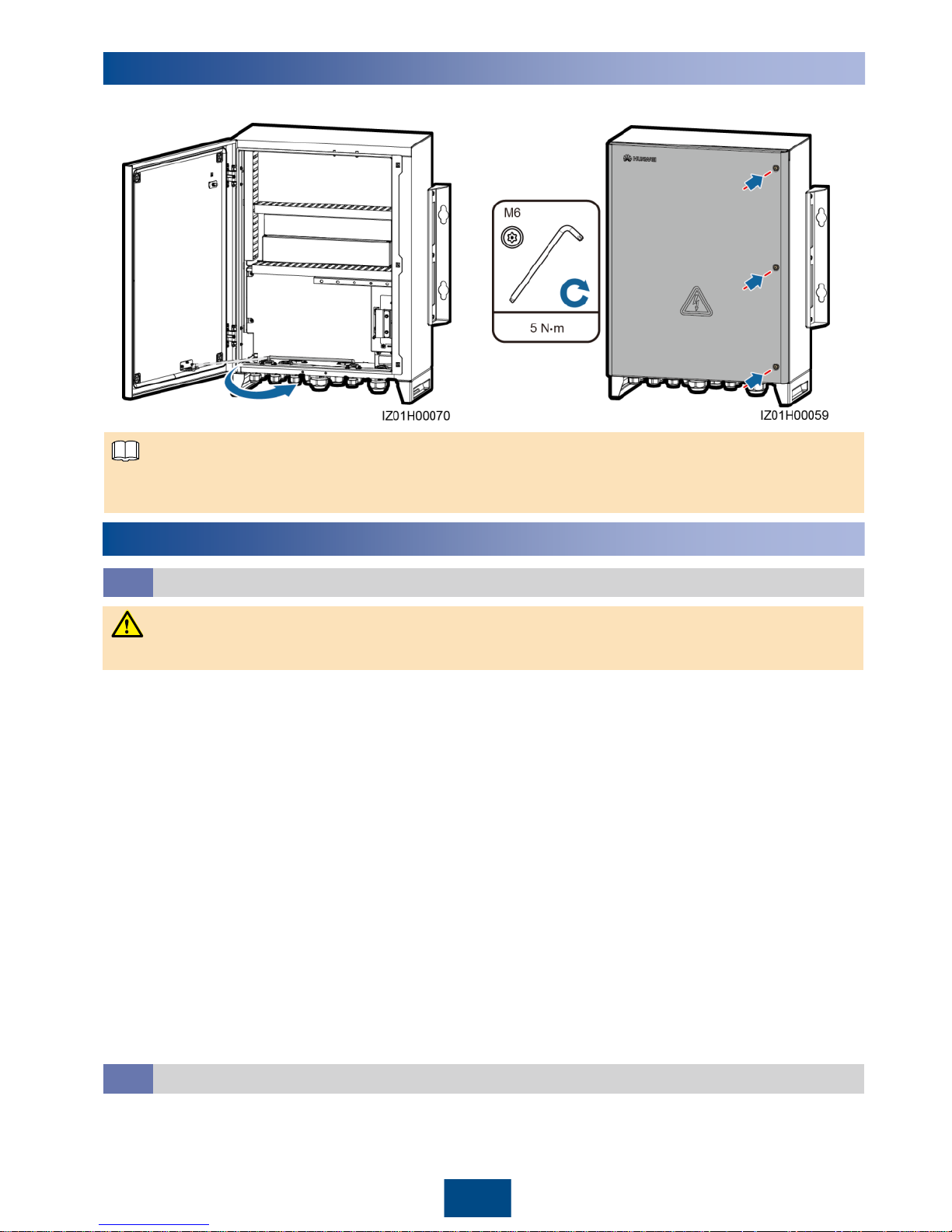
If the screws used for securing the cabinet door are lost, use the security torx screws in the fitting
bag.
Closing the Cabinet Door
1. Install the support bar. 2. Close the cabinet door and tighten the screws.
9
NOTE
DANGER
Page 29
Scan here for more documents:
Scan here for technical support (carrier):
Huawei Technologies Co., Ltd.
Huawei Industrial Base, Bantian, Longgang
Shenzhen 518129 People's Republic of China
www.huawei.com
You can also log in to Huawei technical support website:
http://support.huawei.com
Google Play Huawei App Store
Apple Store
Support WeChat
 Loading...