


ServiceStage
User Guide
Issue 01
Date 2021-04-06
HUAWEI TECHNOLOGIES CO., LTD.

Copyright © Huawei Technologies Co., Ltd. 2021. All rights reserved.
No part of this document may be reproduced or transmitted in any form or by any means without prior
written consent of Huawei Technologies Co., Ltd.
Trademarks and Permissions
and other Huawei trademarks are trademarks of Huawei Technologies Co., Ltd.
All other trademarks and trade names mentioned in this document are the property of their respective
holders.
Notice
The purchased products, services and features are stipulated by the contract made between Huawei and
the customer. All or part of the products, services and features described in this document may not be
within the purchase scope or the usage scope. Unless otherwise specied in the contract, all statements,
information, and recommendations in this document are provided "AS IS" without warranties, guarantees
or representations of any kind, either express or implied.
The information in this document is subject to change without notice. Every eort has been made in the
preparation of this document to ensure accuracy of the contents, but all statements, information, and
recommendations in this document do not constitute a warranty of any kind, express or implied.
Issue 01 (2021-04-06) Copyright © Huawei Technologies Co., Ltd. i

ServiceStage
User Guide Contents
Contents
1 Overview....................................................................................................................................1
2 Permissions Management..................................................................................................... 4
2.1 Creating a User and Granting Permissions.....................................................................................................................4
2.2 Creating a Custom Policy..................................................................................................................................................... 5
2.3 Assigning Permissions on Services that ServiceStage Depends On....................................................................... 6
3 Application Management...................................................................................................... 8
3.1 Creating an Application........................................................................................................................................................ 8
3.2 Creating Application Components.....................................................................................................................................9
3.2.1 Application Components................................................................................................................................................... 9
3.2.2 Quickly Creating a Component.................................................................................................................................... 14
3.2.3 Creating a Microservice Component...........................................................................................................................17
3.2.4 Creating a Web Component.......................................................................................................................................... 20
3.2.5 Creating a Common Component................................................................................................................................. 23
3.3 Deploying Application Components............................................................................................................................... 25
3.3.1 Deployment Mode............................................................................................................................................................ 26
3.3.2 Deploying a Component................................................................................................................................................. 26
3.4 Managing Application Components............................................................................................................................... 31
3.5 Performing Advanced Settings for an Application.................................................................................................... 34
3.5.1 Setting Application Environment Variables..............................................................................................................34
Conguring the Lifecycle of an Application............................................................................................................. 36
3.5.2
3.5.3 Conguring Data Storage...............................................................................................................................................37
3.5.4 Conguring Distributed Sessions................................................................................................................................. 46
3.5.5 Conguring Relational Databases............................................................................................................................... 47
3.6 Building an Application Component.............................................................................................................................. 48
3.7 Pipelining an Application Component........................................................................................................................... 48
3.8 Application
3.8.1 Creating a Secret............................................................................................................................................................... 50
3.8.2 Creating a CongMap......................................................................................................................................................53
Conguration.................................................................................................................................................. 50
4 Environment Management................................................................................................. 56
5 Application O&M...................................................................................................................58
5.1 Maintaining Application Component Instances......................................................................................................... 58
5.2 Adding Labels for Application Component Instances.............................................................................................. 61
Issue 01 (2021-04-06) Copyright © Huawei Technologies Co., Ltd. ii

ServiceStage
User Guide Contents
5.3 Conguring Domain Name Mappings.......................................................................................................................... 62
5.4 Setting Alarm Thresholds for Resource Monitoring..................................................................................................62
5.5 Setting Scaling Policies for Application Component Instances............................................................................. 65
5.6 Setting Scheduling Policies for Application Component Instances......................................................................69
5.7 Setting Upgrade Policies for Application Component Instances.......................................................................... 74
5.8 Setting Custom Metric Monitoring for Application Components........................................................................ 76
5.9 Conguring Application Log Policies............................................................................................................................. 79
5.10 Conguring Application Performance Management............................................................................................. 81
5.11 Conguring Health Check............................................................................................................................................... 82
6 Microservice Governance.....................................................................................................85
6.1 Overview.................................................................................................................................................................................. 85
6.2 Using the Microservice Dashboard................................................................................................................................. 85
6.3 Governing Microservices.....................................................................................................................................................86
6.4 Conguring Microservices.................................................................................................................................................. 93
6.5 Maintaining Microservices................................................................................................................................................. 95
7 Continuous Delivery........................................................................................................... 100
7.1 Overview................................................................................................................................................................................ 100
7.2 Creating a Source Code Build Task...............................................................................................................................101
7.3 Creating a Package Build Task....................................................................................................................................... 105
7.4 Managing Pipelines........................................................................................................................................................... 107
7.5 Authorizing a Repository................................................................................................................................................. 111
8 Software Center...................................................................................................................112
8.1 Software Repository.......................................................................................................................................................... 112
8.1.1 Managing Software Packages.................................................................................................................................... 112
8.1.2 Packaging
8.2 Image Repository................................................................................................................................................................ 117
8.2.1 Uploading an Image...................................................................................................................................................... 117
8.2.2 Managing Images........................................................................................................................................................... 119
8.3 Organization Management.............................................................................................................................................122
Specications of Software Packages...................................................................................................116
9 Infrastructure Management.............................................................................................125
9.1 Cloud Service Engines....................................................................................................................................................... 125
9.1.1 Creating an Exclusive Microservice Engine............................................................................................................ 125
Conguring Backup and Restoration of an Exclusive Microservice Engine................................................ 127
9.1.2
9.1.3 Conguring Public Network Access for an Exclusive Microservice Engine................................................. 128
9.1.4 Viewing the Access Address of a Microservice Engine.......................................................................................129
9.1.5 Viewing Operation Logs of an Exclusive Microservice Engine........................................................................ 130
9.1.6 Upgrading an Exclusive Microservice Engine........................................................................................................ 130
9.1.7 Deleting an Exclusive Microservice Engine............................................................................................................ 131
9.2 VMAgent Manager............................................................................................................................................................ 132
Issue 01 (2021-04-06) Copyright © Huawei Technologies Co., Ltd. iii
ServiceStage
User Guide 1 Overview
1 Overview
ServiceStage is an application management and O&M platform that lets you
deploy, roll out, monitor, and maintain applications all in one place. Java, Go, PHP,
Node.js, Docker, and Tomcat are supported. Web applications, microservice
applications such as Apache ServiceComb, Spring Cloud, Dubbo, and service mesh,
and common applications make it easier to migrate enterprise applications to the
cloud.
This document describes how to use ServiceStage to create, deploy, and maintain
applications and perform service governance.
Console Description
Table 1-1 describes ServiceStage console.
Table 1-1 ServiceStage console
Module
Overview Provides ServiceStage overview, including the ServiceStage
Application
Management
Description
package selection and purchase entry, tutorials, applications,
environments, and components.
● Application List
Provides application lifecycle management, such as
application creation, component addition, component list,
environment view, component deployment, component
details, and O&M.
● Application Component
Displays the components (including static and deployed
components) of the application, and component details and
O&M.
● Application
Supports conguration item and secret management.
Conguration
Issue 01 (2021-04-06) Copyright © Huawei Technologies Co., Ltd. 1

ServiceStage
User Guide 1 Overview
Module Description
Environment
Management
Continuous
Delivery
Environment is a collection of infrastructures, covering
computing, storage, and networks, used for application
deployment and running.
Provides environment creation, editing, and deletion, and
displays resource information in an existing environment.
Supports project build and release.
● Build
The software package or image package can be generated
with a few clicks in job building. In this way, the entire
process of source code pull, compilation, packaging, and
archiving is automatically implemented.
● Pipeline
One-click deployment can be achieved through pipeline. In
this way, the entire process of source code pull, complication,
packaging, archiving, and deployment is automatically
implemented. This
unies the integration environment and
standardizes the delivery process.
● Repository Authorization
You can create repository authorization so that build projects
and application components can use the authorization
information to access the software repository.
Software
Center
Provides functions such as organization management, software
repository, and image repository.
● Organization management is used to isolate images and
assign access permissions (read, write, and manage) to
dierent users.
● Image repositories are used to store and manage Docker
images.
● Software repositories are used to store, manage, and deploy
software packages.
Infrastructure Provides application infrastructure management, such as Cloud
Service Engine (CSE) and VM agent management (VMAgent).
On the CSE page, go to its console to perform microservice
governance.
Operation List After the Cloud Trace Service (CTS) is enabled, the system
automatically traces operations and changes of all cloud
resources of the current tenant and saves the information as
traces for seven days. Advanced functions, such as trace transfer
(long-term storage) and encrypted storage, can be congured
in the tracker list.
Help Center Provides an overview of ServiceStage documentation.
Issue 01 (2021-04-06) Copyright © Huawei Technologies Co., Ltd. 2
NO TE
NO TE
ServiceStage
User Guide 1 Overview
The VM agent management function depends on the ECS and AOM services. If these
services are not installed, the VM agent management function is unavailable.
Package Description
Log in to the ServiceStage console and select an edition on the Overview page.
Currently, ServiceStage provides basic edition and professional edition..
Table 1-2 ServiceStage edition description
Edition Package Description
Basic 20 instances are free to use.
Professional One exclusive CSE engine and AOM enterprise
edition are free to use.
For product pricing of each edition, see Product Pricing Details.
Issue 01 (2021-04-06) Copyright © Huawei Technologies Co., Ltd. 3

ServiceStage
User Guide 2 Permissions Management
2 Permissions Management
Creating a User and Granting Permissions
Creating a Custom Policy
Assigning Permissions on Services that ServiceStage Depends On
2.1 Creating a User and Granting Permissions
This section describes how to use IAM to implement ne-grained permissions
control for your ServiceStage resources. With IAM, you can:
● Create IAM users for employees based on the organizational structure of your
enterprise. Each IAM user has their own security credentials, providing access
to ServiceStage resources.
● Grant only the permissions required for users to perform a task.
● Entrust a HUAWEI CLOUD account or cloud service to perform
on your ServiceStage resources.
If your HUAWEI CLOUD account does not require individual IAM users, skip this
section.
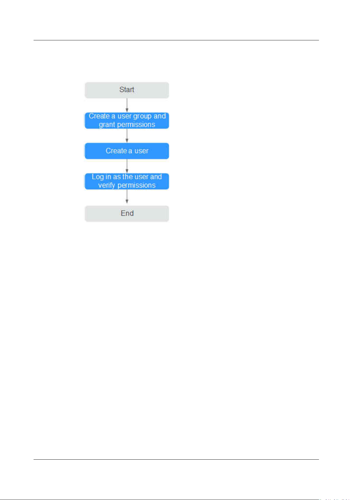
This section describes the procedure for granting permissions (see Figure 2-1).
Prerequisites
Before assigning permissions to user groups, you should learn about the
ServiceStage permissions listed in Permissions Management. For the system
policies of other services, see System Permissions.
ecient O&M
Issue 01 (2021-04-06) Copyright © Huawei Technologies Co., Ltd. 4
ServiceStage
User Guide 2 Permissions Management
Process Flow
Figure 2-1 Process for granting ServiceStage permissions
1. Create a user group and grant permissions to it.
Create a user group on the IAM console, and assign the ServiceStage
ReadOnlyAccess policy to the group.
2. Create a user.
Create a user on the IAM console and add the user to the group created in 1.
3. Log in and verify permissions.
Log in to the ServiceStage console as the created user, and verify that it only
has read permissions for ServiceStage.
– Select ServiceStage from Service List. Choose Application Management
> Application List from the navigation tree. On the page that is
displayed, click Create Application. If a message appears indicating
insucient permissions to access the service, the ServiceStage
ReadOnlyAccess policy has already taken
– Choose any other service in the Service List. If a message appears
indicating
ReadOnlyAccess policy has already taken eect.
insucient permissions to access the service, the ServiceStage
2.2 Creating a Custom Policy
Custom policies can be created as a supplement to the system policies of
ServiceStage.
eect.
You can create custom policies in either of the following ways:
● Visual editor: Select cloud services, actions, resources, and request conditions.
This does not require knowledge of policy syntax.
Issue 01 (2021-04-06) Copyright © Huawei Technologies Co., Ltd. 5

ServiceStage
User Guide 2 Permissions Management
● JSON: Edit JSON policies from scratch or based on an existing policy.
For details, see Creating a Custom Policy. The following section contains
examples of common ServiceStage custom policies.
Example Custom Policy
This procedure creates a policy that an IAM user is prohibited to create and
modify a microservice engine.
{
"Version": "1.1",
"Statement": [
{
"Action": [
"cse:*:*"
],
},
{
"Action": [
"cse:engine:create",
"cse:engine:delete"
],
}
]
}
"Eect": "Allow"
"Eect": "Deny"
A deny policy must be used in conjunction with other policies to take eect. If the
permissions assigned to a user contain both "Allow" and "Deny", the "Deny"
permissions take precedence over the "Allow" permissions.
After authorization, users in the group can verify their permissions using the
console or REST APIs.
The following are the steps to be performed on the console.
1. Log in to HUAWEI CLOUD as an IAM user.
– Account name: Name of the account used to create the IAM user
– Username and password: Username and password
specied for the IAM
user
2. On the ServiceStage console, choose Infrastructure > Cloud Service Engines,
and buy a microservice engine. If error 403 is returned, the permissions are
correct and have already taken
eect.
2.3 Assigning Permissions on Services that ServiceStage Depends On
Granting CCE Namespace Permissions
You can grant only common operation permissions on CCE cluster resources to the
ServiceStage user group using IAM, excluding the namespace permissions of the
clusters with Kubernetes RBAC authentication enabled. Therefore, you need to
separately grant the namespace permissions for the clusters.
Issue 01 (2021-04-06) Copyright © Huawei Technologies Co., Ltd. 6

ServiceStage
User Guide 2 Permissions Management
For details about how to set CCE namespace permissions, see Permissions
Management.
Granting CTS Permissions
Currently, Cloud Trace Service (CTS) does not support ne-grained authorization.
After the permissions are set for ServiceStage using IAM, they do not take eect
for the CTS service on which ServiceStage depends. You need to set the CTS
service permissions separately.
For details about how to set CTS namespace permissions, see Permissions
Management.
Issue 01 (2021-04-06) Copyright © Huawei Technologies Co., Ltd. 7

ServiceStage
User Guide 3 Application Management
3 Application Management
Creating an Application
Creating Application Components
Deploying Application Components
Managing Application Components
Performing Advanced Settings for an Application
Building an Application Component
Pipelining an Application Component
Application
Conguration
3.1 Creating an Application
An application is a service system with functions and consists of one or more
application components.
For example, the weather forecast is an application that contains the weather and
forecast components. ServiceStage organizes multiple components by application,
and supports dark launch and quick cloning of applications in
environments.
Creating an Application
Step 1 Log in to ServiceStage and choose Application Management > Application List.
dierent
Step 2 Click Create Application and set basic application information.
1. Name: Enter an application name. This name cannot be changed after the
application is created.
2. Enterprise Project: Set an enterprise project.
Enterprise projects provide a cloud resource management mode, in which
cloud resources and members are centrally managed by project.
It is available after the enterprise center is enabled.
Issue 01 (2021-04-06) Copyright © Huawei Technologies Co., Ltd. 8

ServiceStage
User Guide 3 Application Management
3. Description: (Optional) Enter an application description.
Step 3 Click OK.
----End
Adding Environment Variables
An environment is a collection of infrastructures, covering computing, storage, and
networks, used for application deployment and running. ServiceStage combines
basic resources (such as CCE and ECS) and optional resources (such as ELB, RDS,
and DCS) in the same VPC into an environment, such as the development
environment, testing environment, pre-production environment, and production
environment. Networks in an environment can communicate with each other. You
can manage resources and deploy services by environment, simplifying
infrastructure O&M.
Environment variables are parameters set in the system or user applications. You
can obtain the values of environment variables by calling APIs. During
deployment, parameters are
the code, which makes the deployment exible.
specied through environment variables instead of in
Step 1 Log in to ServiceStage and choose Application Management > Application List.
Step 2 Click the application name. The Overview page is displayed.
Step 3 Click Environment Variables and select a created environment from the
Environment drop-down list.
Step 4 Click Add Environment Variable and enter the values in Key and Value.
Key indicates the name of the environment variable, and Value indicates the
value of the environment variable. Click Submit.
For example, set Key to User and Value to admin. That is, when the program
code reads the User environment variable, admin is obtained. For example, you
can start subprocesses as the admin user and read
actual execution eect depends on the code.
----End
3.2 Creating Application Components
3.2.1 Application Components
les as the admin user. The
An application component implements a service feature of an application. It is in
the form of code or software packages and can be deployed independently.
After creating an application on ServiceStage, you can add components to the
application. Currently, microservice, web, and common application components are
supported.
You can create a static component by setting the component type, framework,
runtime system, and component source, and then deploy this component.
Issue 01 (2021-04-06) Copyright © Huawei Technologies Co., Ltd. 9
ServiceStage
User Guide 3 Application Management
In the process of adding a component, you can congure the component using a
template (Template) or customize the conguration (Custom).
● Template provides default congurations of the component type, runtime
system, and framework to help you quickly create components.
● Custom allows you to select the desired component type, runtime system,
and proper framework/service mesh.
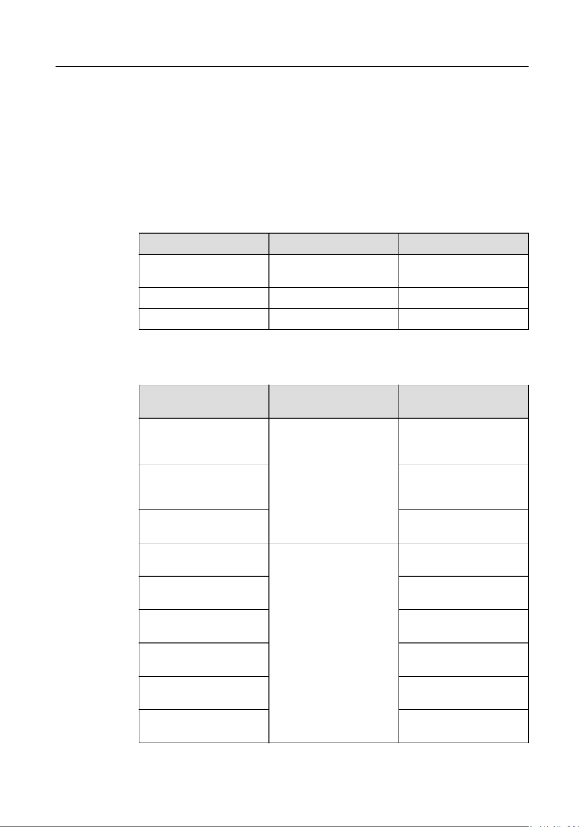
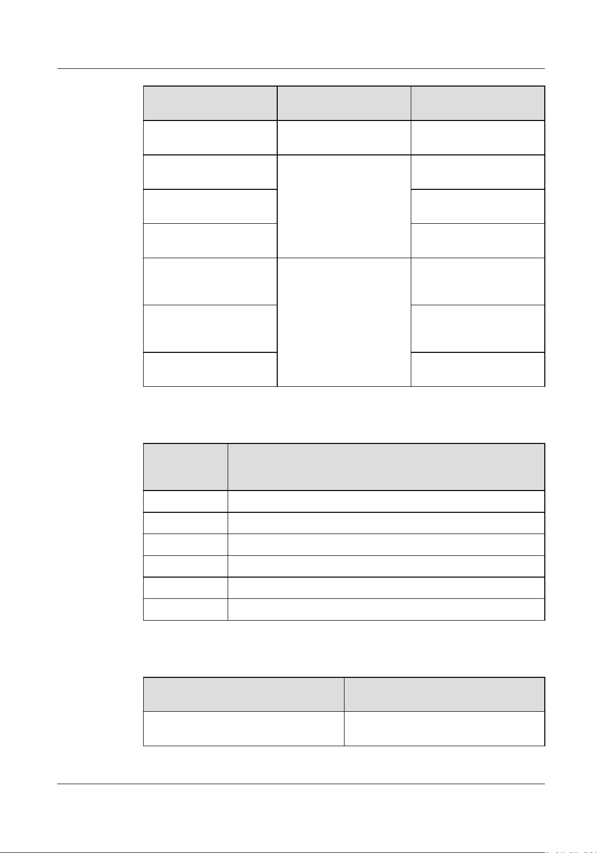
Existing Templates
Table 3-1 Existing templates
Type Runtime System Framework
ServiceComb
MicroService
SpringCloud MicroService Java8 SpringCloud
Web(Tomcat) WebApp Tomcat8 Web
Microservice Components
Supported Runtime
System
Java8 Java Chassis Source code repository,
Tomcat8 Source code repository,
Docker This parameter does not
Java8 Java Chassis
Supported Framework/
Service Mesh
Supported Source
Code/Software Package
template, and JAR
package
template, and WAR
package
need to be set.
Java8 Mesher Source code repository
and JAR package
Tomcat8 Source code repository
and WAR package
Node.js8 Source code repository
and ZIP package
Php7 Source code repository
and ZIP package
Docker This parameter does not
need to be set.
Python3 Source code repository
and ZIP package
Issue 01 (2021-04-06) Copyright © Huawei Technologies Co., Ltd. 10
ServiceStage
User Guide 3 Application Management
Supported Runtime
System
Docker Go Chassis This parameter does not
Java8 Spring Cloud Source code repository
Tomcat8 Source code repository
Docker This parameter does not
Java8 Dubbo Source code repository,
Tomcat8 Source code repository,
Docker This parameter does not
Supported Framework/
Service Mesh
Supported Source
Code/Software Package
need to be set.
and JAR package
and WAR package
need to be set.
template, and JAR
package
template, and WAR
package
need to be set.
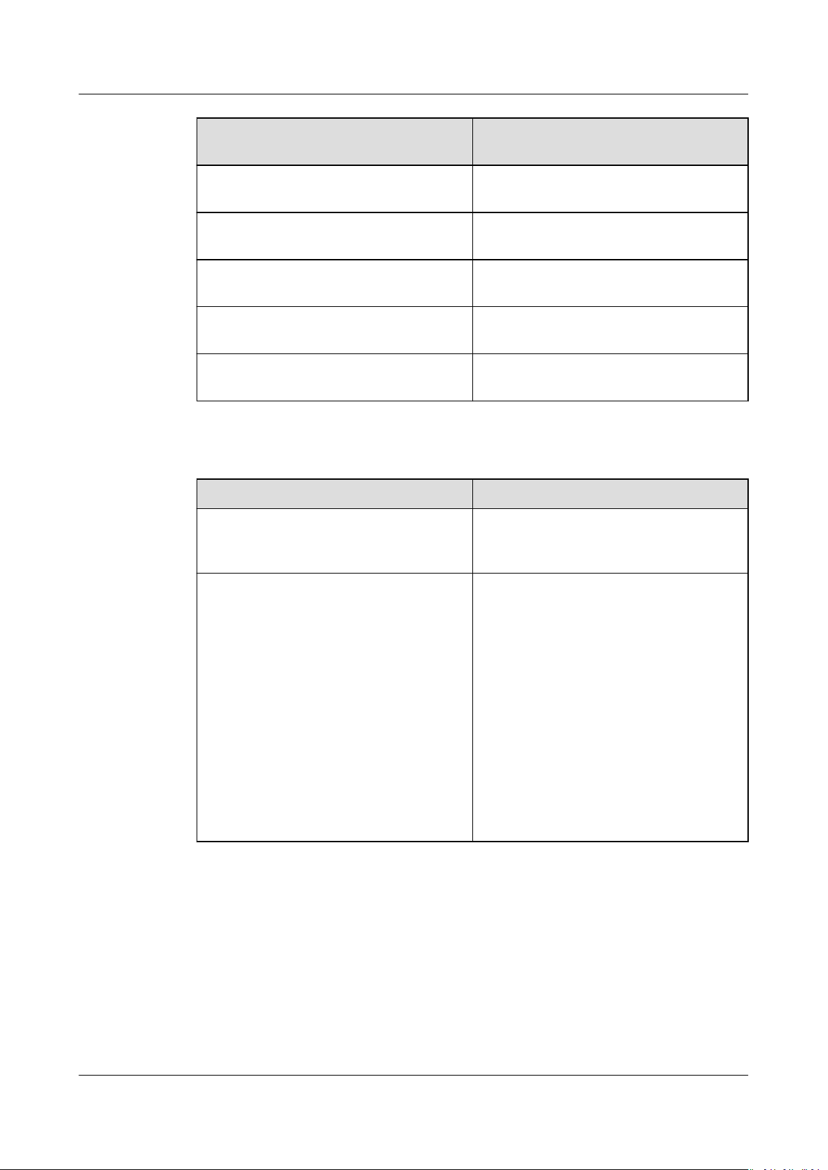
Web Application Components
Supported
Runtime
System
Java8 Source code repository, template, and JAR package
Nodejs8 Source code repository, template, and ZIP package
Php7 Source code repository, template, and ZIP package
Tomcat8 Source code repository, template, and WAR package
Docker This parameter does not need to be set.
Python3 Source code repository and ZIP package
Supported Source Code/Software Package
Common Components
Supported Runtime System
Supported Source Code/Software
Package
Java8 Source code repository, template, and
JAR package
Issue 01 (2021-04-06) Copyright © Huawei Technologies Co., Ltd. 11
ServiceStage
User Guide 3 Application Management
Supported Runtime System Supported Source Code/Software
Package
Tomcat8 Source code repository, template, and
WAR package
Node.js8 Source code repository, template, and
ZIP package
Php7 Source code repository, template, and
ZIP package
Docker This parameter does not need to be
set.
Python3 Source code repository and ZIP
package
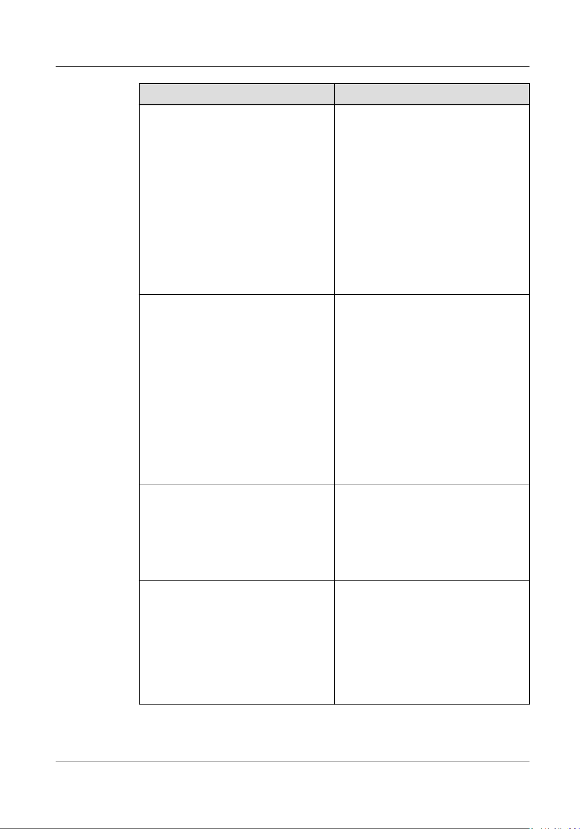
Component Source
Component Source Description
Source code repository Create authorization by referring to
Authorizing a Repository and set the
code source.
JAR package Supports the following uploading
modes:
1. Select the corresponding software
package from the SWR software
repository. You need to upload the
software package to the software
repository in advance. For details,
see Uploading the Software
Package.
2. Select the corresponding software
package from OBS. You need to
upload the software package to the
OBS bucket in advance. For details,
see Uploading a File.
Issue 01 (2021-04-06) Copyright © Huawei Technologies Co., Ltd. 12
ServiceStage
User Guide 3 Application Management
Component Source Description
WAR package Supports the following uploading
modes:
1. Select the corresponding software
package from the SWR software
repository. You need to upload the
software package to the software
repository in advance. For details,
see Uploading the Software
Package.
2. Select the corresponding software
package from OBS. You need to
upload the software package to the
OBS bucket in advance. For details,
see Uploading a File.
ZIP package Supports the following uploading
modes:
1. Select the corresponding software
package from the SWR software
repository. You need to upload the
software package to the software
repository in advance. For details,
see Uploading the Software
Package.
2. Select the corresponding software
package from OBS. You need to
upload the software package to the
OBS bucket in advance. For details,
see Uploading a File.
Image package If you use a private image to create
your containerized application, upload
the private image to the image
repository. Choose Software Center >
Image Repository and upload the
image to the image repository by
referring to Managing Images.
Template Create authorization by referring to
Authorizing a Repository and set the
organization and repository names.
ServiceStage provides component
templates. You can select a template
to quickly create an application and
generate a development project in the
congured code repository. For details,
see Template Framework.
Issue 01 (2021-04-06) Copyright © Huawei Technologies Co., Ltd. 13
ServiceStage
User Guide 3 Application Management
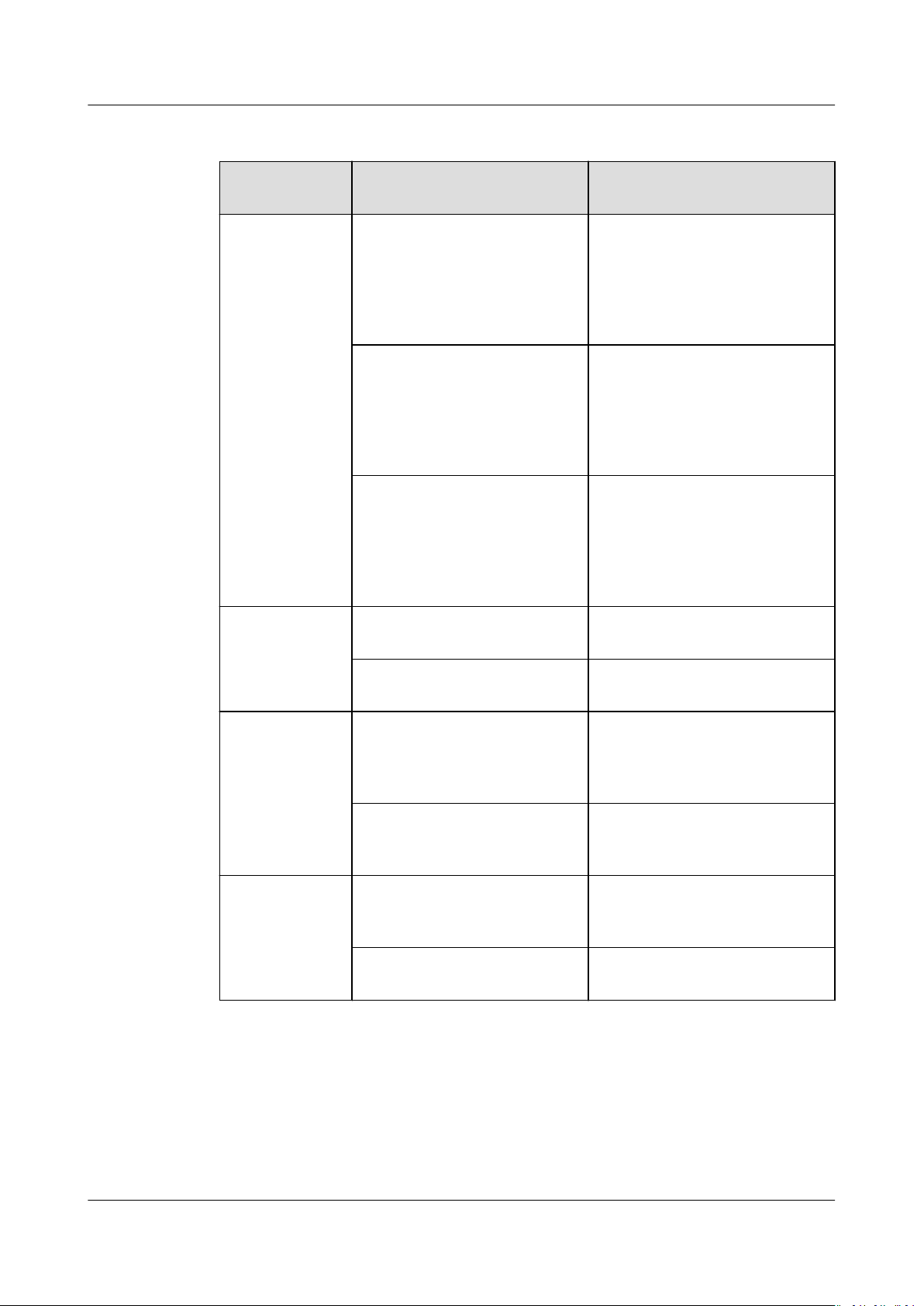
Template Framework
Runtime
System
Java8 CSE-Java (SpringMVC) Based on the ServiceComb
Tomcat8 SpringBoot-Webapp-Tomcat Web applications, running on
Framework Provided by the
Template
CSE-Java (JAX-RS) Based on the ServiceComb
CSE-Java (POJO) Based on the ServiceComb
Framework Description
microservice development
framework, supports
SpringMVC annotations and
uses the SpringMVC style to
develop microservices.
microservice development
framework, supports JAX-RS
annotations and uses the JAXRS mode to develop
microservices.
microservice development
framework, supports APIs and
API implementation, and uses
transparent RPC to develop
microservices.
an independent web server.
SpringBoot-WebServiceTomcat
Nodejs8 Express A Node.js web framework that
Koa Next-generation web
Php7 Laravel A PHP development
Slim A lightweight micro-PHP
3.2.2 Quickly Creating a Component
ServiceStage provides three default templates. For details, see Existing Templates.
A template provides default
runtime system, and framework/service mesh to help you quickly create a
component.
congurations of the component type, language/
Web services, running on an
independent web server.
supports high compatibility,
and fast and simple
deployment.
development framework
based on the Node.js platform.
framework for web
developers.
framework.
Issue 01 (2021-04-06) Copyright © Huawei Technologies Co., Ltd. 14
ServiceStage
User Guide 3 Application Management
Prerequisites
1. An application has been created cause components can only be added to
applications. For details, see Creating an Application.
2. If you create a microservice component based on the source code repository
or template, create repository authorization rst. For details, see Authorizing
a Repository.
3. If you create a microservice component based on the software package,
upload the software package to the software repository or OBS bucket.
– Upload the software package to the software repository. For details, see
Uploading the Software Package.
– Upload the software package to OBS. For details, see Uploading a File.
Procedure
Step 1 Log in to ServiceStage and choose Application Management > Application List.
Step 2 Select the created application and click Create Component in the Operation
column.
Step 3 Select Template for
Step 4 Congure component information according to the following table. Parameters
marked with an asterisk (*) are mandatory.
Table 3-2 Basic component information
Parameter
*Name Component name.
Conguration Method, select a template, and click Next.
Description
Issue 01 (2021-04-06) Copyright © Huawei Technologies Co., Ltd. 15

ServiceStage
User Guide 3 Application Management
Parameter Description
*Source Code/
Software
Package
● Select Source code repository.
– Create authorization by referring to Authorizing a
Repository and set the code source.
– Set Build parameters to build the application
component.
Set Command, Organization, and CPU Architecture,
and select a cluster based on service requirements.
You can also specify Node Label to deliver the build
task to a
xed node based on the node label. For
details about how to add a node label, see Node
Management.
NOTICE
If Custom command is selected for Command:
Exercise caution when inputting sensitive information in the
echo, cat, or debug command, or encrypt sensitive
information to avoid information leakage.
● Select JAR package or WAR package.
NOTE
Select JAR package if Java8 is selected as the Runtime System.
Select WAR package if Tomcat8 is selected as the Runtime
System.
1. Select Upload Method.
Select the corresponding software package from the
SWR software repository. Upload the software package
to the software repository in advance. For details, see
Uploading the Software Package.
Upload the software package to OBS. For details, see
Uploading a File.
2. (Optional) Set Build parameters to build the
application component.
Set Organization and CPU Architecture, and select a
cluster based on service requirements.
You can also specify Node Label to deliver the build
task to a
xed node based on the node label. For
details about how to add a node label, see Node
Management.
● Set the following parameters if Template is selected.
1. Select the template framework. ServiceStage provides
template frameworks. You can select one to quickly
create an application component.
2. Set Code Archive. See Authorizing a Repository to
create authorization and set Username/Organization
and Repository.
Step 5 Complete component creation.
● Click Create Now to create a static component.
Issue 01 (2021-04-06) Copyright © Huawei Technologies Co., Ltd. 16

ServiceStage
User Guide 3 Application Management
● Click Create and Deploy. The deployment page is displayed. For details, see
Deploying a Component.
After the component is created, you can view the component status in the
Component List on the Overview tab.
----End
3.2.3 Creating a Microservice Component
ServiceStage provides a microservice framework that enables you to develop and
deploy applications on the cloud. It provides code framework generation, service
registry and discovery, load balancing, and service reliability including fault
tolerance, circuit breaker, rate limiting, and service degradation. This section
describes how to create a static microservice application component using
ServiceStage. For details about how to deploy a component, see Deploying a
Component.
Prerequisites
1. An application has been created cause components can only be added to
applications. For details, see Creating an Application.
2. If you create a microservice component based on the source code repository
or template, create repository authorization
a Repository.
3. If you create a microservice component based on the software package,
upload the software package to the software repository or OBS bucket.
– Upload the software package to the software repository. For details, see
Uploading the Software Package.
– Upload the software package to OBS. For details, see Uploading a File.
rst. For details, see Authorizing
Procedure
Step 1 Log in to ServiceStage and choose Application Management > Application List.
Step 2 Select the created application and click Create Component in the Operation
column.
Step 3 Select Custom for
Component Type, and click Next.
Step 4 Select Runtime System and click Next.
Dierent frameworks support dierent runtime systems. For details, see
Microservice Components.
Step 5 Select Framework/Service Mesh.
For details about the framework/service mesh, see Microservice Components.
Step 6 Select whether you want to save the preceding
future use.
● If you select this function, enter a template name. Then, go to Step 7.
● If you do not select this function, go to Step 7.
Issue 01 (2021-04-06) Copyright © Huawei Technologies Co., Ltd. 17
Conguration Method and Microservice for Select
congurations as a template for
ServiceStage
User Guide 3 Application Management
Step 7 Check whether Docker is selected in Step 4.
● If yes, click Next and go to Step 8.
● If no, click Next and go to Step 9.
Step 8 Create a Docker component.
1. Enter a component name.
2. Create a component.
– Click Create Now to create a static component.
– Click Create and Deploy. The deployment page is displayed. For details,
see Deploying a Component.
3. No further action is required.
After the component is created, you can view the component status in the
Component List on the Overview tab.
Step 9
Congure component information according to the following table. Parameters
marked with an asterisk (*) are mandatory.
Table 3-3 Basic component information
Parameter Description
*Name Component name.
Issue 01 (2021-04-06) Copyright © Huawei Technologies Co., Ltd. 18
ServiceStage
User Guide 3 Application Management
Parameter Description
*Source Code/
Software
Package
● Select Source code repository.
1. Create authorization by referring to Authorizing a
Repository and set the code source.
2. Set Build parameters to build the application
component.
Set Command, Organization, and CPU Architecture,
and build a cluster based on service requirements.
You can also specify Node Label to deliver the build
task to a
xed node based on the node label. For
details about how to add a node label, see Node
Management.
NOTICE
If Custom command is selected for Command:
Exercise caution when inputting sensitive information in the
echo, cat, or debug command, or encrypt sensitive
information to avoid information leakage.
● Select JAR package, WAR package, or ZIP package.
NOTE
Select JAR package if Java8 is selected as the Runtime System.
Select WAR package if Tomcat8 is selected as the Runtime
System.
Select ZIP package if Nodejs8, Php7, or Python3 is selected as
the Runtime System.
1. Select Upload Method.
Select the corresponding software package from the
SWR software repository. Upload the software package
to the software repository in advance. For details, see
Uploading the Software Package.
Upload the software package to OBS. For details, see
Uploading a File.
2. (Optional) Set Build parameters to build the
application component.
Set Organization and CPU Architecture, and build a
cluster based on service requirements.
You can also specify Node Label to deliver the build
task to a
xed node based on the node label. For
details about how to add a node label, see Node
Management.
● Set the following parameters if Template is selected.
1. ServiceStage provides template frameworks. You can
select one to quickly create an application component.
2. Set Code Archive. See Authorizing a Repository to
create authorization and set Username/Organization
and Repository.
NOTE
This parameter is invalid if you select Mesher or Spring Cloud for
Framework/Service Mesh in Step 5.
Issue 01 (2021-04-06) Copyright © Huawei Technologies Co., Ltd. 19

ServiceStage
User Guide 3 Application Management
Step 10 Create a component.
● Click Create Now to create a static component.
● Click Create and Deploy. The deployment page is displayed. For details, see
Deploying a Component.
After the component is created, you can view the component status in the
Component List on the Overview tab.
----End
3.2.4 Creating a Web Component
This section describes how to create a static web application component using
ServiceStage. For details, see Deploying a Component.
Prerequisites
1. An application has been created cause components can only be added to
applications. For details, see Creating an Application.
2. If you create a microservice component based on the source code repository
or template, create repository authorization rst. For details, see Authorizing
a Repository.
3. If you create a microservice component based on the software package,
upload the software package to the software repository or OBS bucket.
– Upload the software package to the software repository. For details, see
Uploading the Software Package.
– Upload the software package to OBS. For details, see Uploading a File.
Procedure
Step 1 Log in to ServiceStage and choose Application Management > Application List.
Step 2 Select the created application and click Create Component in the Operation
Step 3 Select Custom for
Step 4 Select Runtime System and click Next.
Step 5 Select whether you want to save the preceding congurations as a template for
Step 6 Check whether Docker is selected in Step 4.
column.
Conguration Method, select Web for Component Type, and
click Next.
Dierent frameworks support dierent runtime systems. For details, see
Microservice Components.
future use.
● If you select this function, enter a template name. Then, go to Step 6.
● If you do not select this function, go to Step 6.
● If yes, click Next and go to Step 7.
● If no, click Next and go to Step 8.
Issue 01 (2021-04-06) Copyright © Huawei Technologies Co., Ltd. 20
ServiceStage
User Guide 3 Application Management
Step 7 Create a Docker component.
1. Enter a component name.
2. Create a component.
– Click Create Now to create a static component.
– Click Create and Deploy. The deployment page is displayed. For details,
see Deploying a Component.
3. No further action is required.
After the component is created, you can view the component status in the
Component List on the Overview tab.
Step 8
Congure component information according to the following table. Parameters
marked with an asterisk (*) are mandatory.
Table 3-4 Basic component information
Parameter Description
*Name Component name.
Issue 01 (2021-04-06) Copyright © Huawei Technologies Co., Ltd. 21

ServiceStage
User Guide 3 Application Management
Parameter Description
*Source Code/
Software
Package
● Select Source code repository.
1. Create authorization by referring to Authorizing a
Repository and set the code source.
2. Set Build parameters to build the application
component.
Set Command, Organization, and CPU Architecture,
and select a cluster based on service requirements.
You can also specify Node Label to deliver the build
task to a
xed node based on the node label. For
details about how to add a node label, see Node
Management.
NOTICE
If Custom command is selected for Command:
Exercise caution when inputting sensitive information in the
echo, cat, or debug command, or encrypt sensitive
information to avoid information leakage.
● Select JAR package, WAR package, or ZIP package.
NOTE
Select JAR package if Java8 is selected as the Runtime System.
Select WAR package if Tomcat8 is selected as the Runtime
System.
Select ZIP package if Nodejs8, Php7, or Python3 is selected as
the Runtime System.
1. Select Upload Method.
Select the corresponding software package from the
SWR software repository. Upload the software package
to the software repository in advance. For details, see
Uploading the Software Package.
Upload the software package to OBS. For details, see
Uploading a File.
2. (Optional) Set Build parameters to build the
application component.
Set Organization and CPU Architecture, and select a
cluster based on service requirements.
You can also specify Node Label to deliver the build
task to a
xed node based on the node label. For
details about how to add a node label, see Node
Management.
● Set the following parameters if Template is selected.
1. ServiceStage provides template frameworks. You can
select one to quickly create an application component.
2. Set Code Archive. See Authorizing a Repository to
create authorization and set Username/Organization
and Repository.
NOTE
This parameter is invalid if you select Python3 for Runtime
System in Step 4.
Issue 01 (2021-04-06) Copyright © Huawei Technologies Co., Ltd. 22

ServiceStage
User Guide 3 Application Management
Step 9 Create a component.
● Click Create Now to create a static component.
● Click Create and Deploy. The deployment page is displayed. For details, see
Deploying a Component.
After the component is created, you can view the component status in the
Component List on the Overview tab.
----End
3.2.5 Creating a Common Component
This section describes how to create a static common application component
using ServiceStage. For details about how to deploy a component, see Deploying
a Component.
Prerequisites
Procedure
Step 1 Log in to ServiceStage and choose Application Management > Application List.
Step 2 Select the created application and click Create Component in the Operation
Step 3 Select Custom for
Step 4 Select Runtime System and click Next.
1. An application has been created cause components can only be added to
applications. For details, see Creating an Application.
2. If you create a microservice component based on the source code repository
or template, create repository authorization
a Repository.
3. If you create a microservice component based on the software package,
upload the software package to the software repository or OBS bucket.
– Upload the software package to the software repository. For details, see
Uploading the Software Package.
– Upload the software package to OBS. For details, see Uploading a File.
column.
Conguration Method, select Common for Component Type,
and click Next.
rst. For details, see Authorizing
Dierent frameworks support dierent runtime systems. For details, see
Microservice Components.
Step 5 Select whether you want to save the preceding congurations as a template for
future use.
● If you select this function, enter a template name. Then, go to Step 6.
● If you do not select this function, go to Step 6.
Step 6 Check whether Docker is selected in Step 4.
● If yes, click Next and go to Step 7.
Issue 01 (2021-04-06) Copyright © Huawei Technologies Co., Ltd. 23

ServiceStage
User Guide 3 Application Management
● If no, click Next and go to Step 8.
Step 7 Create a Docker component.
1. Enter a component name.
2. Create a component.
– Click Create Now to create a static component.
– Click Create and Deploy. The deployment page is displayed. For details,
see Deploying a Component.
3. No further action is required.
After the component is created, you can view the component status in the
Component List on the Overview tab.
Step 8
Congure component information according to the following table. Parameters
marked with an asterisk (*) are mandatory.
Parameter Description
*Name Component name.
*Source Code/
Software
Package
● Source code repository: Create authorization by referring
to Authorizing a Repository and set the code source.
● JAR package/WAR package/ZIP package: Set Upload
Method.
Select the corresponding software package from the SWR
software repository. Upload the software package to the
software repository in advance. For details, see Uploading
the Software Package.
Upload the software package to OBS. For details, see
Uploading a File.
NOTE
Select JAR package if Java8 is selected as the Runtime System.
Select WAR package if Tomcat8 is selected as the Runtime
System.
Select ZIP package if Nodejs8, Php7, or Python3 is selected as
the Runtime System.
● Set the following parameters if Template is selected.
1. ServiceStage provides template frameworks. You can
select one to quickly create an application component.
2. Set Code Archive. See Authorizing a Repository to
create authorization and set Username/Organization
and Repository.
NOTE
This parameter is invalid if you select Python3 for Runtime
System in Step 4.
Issue 01 (2021-04-06) Copyright © Huawei Technologies Co., Ltd. 24

ServiceStage
User Guide 3 Application Management
Parameter Description
*Python
framework
This parameter is mandatory if you select Python3 in Step 4.
Set Module Name and Variable Name for all Python
frameworks except Python3-Django.
● If the entry point le of the Python project is server.py,
Module Name is server.
● If the application function of the server.py entry point
of the Python project is app=get_wsgi_application(),
Variable Name is app.
Build ● If Source code repository is selected for Source Code/
Software Package, set Build parameters to build the
application component.
Set Command, Organization, and CPU Architecture, and
select a cluster based on service requirements.
You can also specify Node Label to deliver the build task
xed node based on the node label. For details about
to a
how to add a node label, see Node Management.
NOTICE
If Custom command is selected for Command:
Exercise caution when inputting sensitive information in the echo,
cat, or debug command, or encrypt sensitive information to
avoid information leakage.
● (Optional) If JAR package, WAR package, or ZIP
package is selected for Source Code/Software Package,
set Build parameters to build the application component.
Set Organization and CPU Architecture, and select a
cluster based on service requirements.
You can also specify Node Label to deliver the build task
xed node based on the node label. For details about
to a
how to add a node label, see Node Management.
le
Step 9 Create a component.
● Click Create Now to create a static component.
● Click Create and Deploy. The deployment page is displayed. For details, see
Deploying a Component.
After the component is created, you can view the component status in the
Component List on the Overview tab.
----End
3.3 Deploying Application Components
Issue 01 (2021-04-06) Copyright © Huawei Technologies Co., Ltd. 25

ServiceStage
User Guide 3 Application Management
3.3.1 Deployment Mode
Deploying a Component Using CCE
Cloud Container Engine (CCE) provides highly scalable, high-performance,
enterprise-class Kubernetes clusters and supports Docker containers. With CCE,
you can easily deploy, manage, and scale containerized applications on the cloud
platform.
If the build function is not enabled for the created component, the component
cannot be deployed using a container.
Deploying a Component Using VM
The created component can be deployed using a VM only when Java8, Tomcat8,
or Nodejs8 is selected for Select Runtime System.
3.3.2 Deploying a Component
Prerequisites
This section describes how to deploy static components in the corresponding
environment.
When creating an application component, you can also select Create and Deploy.
The deployment procedure is the same as that described in this section.
1. An application component has been created or is being created, and has been
congured. For details, see Creating Application Components.
2. The environment has been created. For details, see Environment
Management.
3. If you deploy components based on software packages or image packages,
you need to upload the software packages or image packages.
– Upload the software package to the software repository. For details, see
Uploading the Software Package.
– Upload the software package to OBS. For details, see Uploading a File.
– Upload the image package to the image repository. For details, see
Uploading an Image.
Congure the AK/SK. For details, see Checking and Conguring the AKSK
4.
Authentication Mode.
Procedure
Step 1 Log in to ServiceStage and choose Application Management >Application List.
Step 2 Click the name of the created application. The Overview page is displayed.
Step 3 On the Component List tab, select a created component and click Deploy in the
Operation column.
Step 4 Set basic parameters. Parameters marked with an asterisk (*) are mandatory.
Issue 01 (2021-04-06) Copyright © Huawei Technologies Co., Ltd. 26

ServiceStage
User Guide 3 Application Management
Parameter Description
*Environment Select an environment you created.
NOTE
Only the environment of the same enterprise project can be selected.
*Version Component version number, for example, 1.0.0.
Description Provides supplementary information about the component.
*Deployment
System
Supports Cloud Container Engine, and VM.
For details, see Deployment Mode.
*Resource Type This parameter is valid when VM is selected for Deployment
System.
AS Groups and Elastic Cloud Servers (ECSs) are supported.
*Basic Resource The basic resources contained in the selected environment
are automatically loaded. Select the resources as required.
*Instances Number of instances in an application component. An
application component can have one or more instances. You
can specify the number of instances as required.
Conguring multiple instances for an application component
ensures high reliability of the application component. For
such a component, if an instance is faulty, the component
can still run properly.
NOTE
This parameter is not displayed when you select VM deployment.
The number of component instances is determined by the number of
Basic Resources.
*Resource Quota Components cannot be scheduled to nodes whose residual
resources are fewer than the requested amount. For details
about how to congure the request and limit parameters,
see Managing Resources for Containers.
You can customize CPU and Memory as required.
NOTE
This parameter is not displayed during deployment when the
component type is Common and the runtime system is Docker.
Component
Status
Sets the component status as required.
NOTE
This parameter is available when the component type is Common,
the runtime system is Docker, and Cloud Container Engine is
selected for Deployment System.
Step 5 Click Next to
congure the component.
● When the component type is Common and the runtime system is Docker,
perform the following operations:
a. Select an image. Multiple containers are supported. You can click Add
Container to add an image.
Issue 01 (2021-04-06) Copyright © Huawei Technologies Co., Ltd. 27

ServiceStage
User Guide 3 Application Management
b. Select an image version.
c. Enter a container name.
d. (Optional) Set Resource Quota. Components cannot be scheduled to
nodes whose residual resources are fewer than the requested amount. For
details about how to congure the request and limit parameters, see
Managing Resources for Containers. You can customize CPU and
Memory as required.
e. (Optional) Set advanced parameters.
▪ Choose Advanced Settings > Component
environment variables. For details, see Setting Application
Environment Variables.
Conguration and set
▪ Choose Advanced Settings > Deployment Conguration.
○ Set Startup Command and Lifecycle. For details, see
Conguring the Lifecycle of an Application.
○ Set Data Storage. For details, see
▪ Choose Advanced
Set Log Collection. For details, see Conguring Application
○
Log Policies.
Set Health Check. For details, see Conguring Health Check.
○
f. (Optional) Enable Public Network Access.
i. Set Public Network Load Balancer.
Select the created load balancer.
If no load balancer exists, click Add Load Balancer to create one. For
details, see Using Shared Load Balancers — Entry Level.
ii. (Optional) Set HTTPS.
If HTTPS is enabled, click Use existing to select an existing
certicate.
If no certicate exists, click Create new to create a server certicate.
For details about how to create a server certicate, see Creating a
Certicate.
iii. Set Domain Name.
Enter a customize domain name if Bound is selected. For details, see
Conguring Domain Name Mappings.
iv. Set Listening Port.
Set the listening port of the application process.
g. (Optional) Set Database.
Select Distributed session. For details, see
Sessions.
Select RDS DB instance. For details, see Conguring Relational
Databases.
h. (Optional) Set Local Time.
Change the time zone of the container node. By default, the time zone is
the same as that of the region where the container node is located.
Conguration > O&M Monitoring.
Conguring Data Storage.
Conguring Distributed
Issue 01 (2021-04-06) Copyright © Huawei Technologies Co., Ltd. 28

ServiceStage
User Guide 3 Application Management
i. (Optional) Set Scheduling Policies. For details, see Setting Scheduling
Policies for Application Component Instances.
j. (Optional) Set Upgrade Policies. For details, see Setting Upgrade
Policies for Application Component Instances.
k. (Optional) Set Performance Management. For details, see
Application Performance Management.
● For other types of components, perform the following operations:
a. Set Image.
▪ If the application source is a software package, source code, or
template, the
loaded.
congured static component information will be
▪ If Runtime System is set to Docker, select an image package from
the SWR image repository.
b. (Optional) Enable Public Network Access.
i. Set Public Network Load Balancer.
Select the created load balancer.
If no load balancer exists, click Add Load Balancer to create one. For
details, see Using Shared Load Balancers — Entry Level.
ii. (Optional) Set HTTPS.
If HTTPS is enabled, click Use existing to select an existing
certicate.
If no certicate exists, click Create new to create a server certicate.
For details about how to create a server certicate, see Creating a
Certicate.
Conguring
iii. Set Domain Name.
Enter a customize domain name if Bound is selected. For details, see
Conguring Domain Name Mappings.
iv. (Optional) Set Listening Port.
Listening port of an application process. If Tomcat8 is selected as the
Runtime System, this port is set to 8080 by default. You can
customize this port.
c. (Optional) Set JVM.
This parameter is mandatory when Runtime System is set to Java8 or
Tomcat8.
Enter the JVM parameter, for example, -Xms256m -Xmx1024m. Multiple
parameters are separated by spaces. If the parameter is left blank, the
default value is used.
d. (Optional) Congure Tomcat parameters.
This parameter is mandatory when Runtime System is set to Tomcat8.
i. Select Parameter settings. The Tomcat dialog box is displayed.
ii. Click Use Sample Code and edit the template
requirements.
iii. Click OK.
le based on service
Issue 01 (2021-04-06) Copyright © Huawei Technologies Co., Ltd. 29

ServiceStage
User Guide 3 Application Management
e. (Optional) Congure Cloud Service Engine.
This parameter is mandatory for microservice components.
By default, the microservice engine added in the environment is selected.
For details about how to create a microservice engine, see Creating an
Exclusive Microservice Engine.
f. (Optional) Set Database.
Select Distributed session. For details, see
Sessions.
Select RDS DB instance. For details, see
Databases.
g. (Optional) Set Local Time.
Change the time zone of the container. By default, the time zone is the
same as that of the region where the container node is located.
h. (Optional) Set advanced parameters.
If the deployment system is set to VM, only environment variables can be
set.
Conguring Distributed
Conguring Relational
▪ Choose Advanced Settings > Component
environment variables. For details, see Setting Application
Environment Variables.
Choose Advanced Settings > Deployment
▪
Set Startup Command and Lifecycle. For details, see
○
Conguring the Lifecycle of an Application.
Set Data Storage. For details, see
○
Set Scheduling Policy. For details, see Setting Scheduling
○
Policies for Application Component Instances.
Set Upgrade Policy. For details, see Setting Upgrade Policies
○
for Application Component Instances.
Choose Advanced
▪
Set Log Collection. For details, see Conguring Application
○
Log Policies.
Set Health Check. For details, see
○
Set Performance Management. For details, see Conguring
○
Application Performance Management.
Conguration > O&M Monitoring.
Conguration and set
Conguration.
Conguring Data Storage.
Conguring Health Check.
○ Set O&M Policy. For details, see Setting Custom Metric
Monitoring for Application Components.
Step 6 Click Next,
After the component is deployed, you can view the component status in the
Environment View on the Overview tab.
----End
Issue 01 (2021-04-06) Copyright © Huawei Technologies Co., Ltd. 30
conrm the specications, and click Deploy.

ServiceStage
User Guide 3 Application Management
3.4 Managing Application Components
After a component is created or deployed, you can perform the following
management operations:
● Viewing Application Components: View the list of components created
under the application.
● Deploying a Component: Deploy the created static components.
● Updating Component Source: Update the source code/software package,
version, and environment
whose runtime system is Docker do not support this operation.
● Deleting Components: Delete the created components.
● Creating a Pipeline for a Component: One-click deployment can be achieved
through pipeline. In this way, the entire process of source code pull,
complication, packaging, archiving, and deployment is automatically
implemented. This
delivery process.
● Viewing Application Component Building: View the status of the
application component building project.
● Maintaining Component Instances: Maintain the deployed application
component instances.
● Managing Component Instance Access Mode: Set the access mode of the
component instances.
unies the integration environment and standardizes the
conguration of the components. Components
Viewing Application Components
Step 1 Log in to ServiceStage and choose Application Management >Application List.
Step 2 Click the name of the created application. The Overview page is displayed.
Step 3 Click the Component List tab to view the list of components created for the
application.
----End
Deploying a Component
For details about how to deploy a component, see Deploying a Component.
Updating Component Source
After a component is created, you can update the source code/software package,
version, and environment
Components whose runtime system is Docker do not support this operation.
Step 1 Log in to ServiceStage and choose Application Management >Application List.
Step 2 Click the name of the created application. The Overview page is displayed.
conguration of the component.
Step 3 Click the Component List tab.
Issue 01 (2021-04-06) Copyright © Huawei Technologies Co., Ltd. 31

ServiceStage
User Guide 3 Application Management
● To update the source of a single component, select the component and click
Update Source in the Operation column.
● To update the component sources in batches, select multiple components and
click Update Component Source.
Step 4 Set Source Code Repository/Software Package.
● Source code repository: Create authorization by referring to Authorizing a
Repository and set the code source.
● Software Package:
– Click Replace Software Package and select the corresponding software
package from the SWR software repository. Upload the software package
to the software repository in advance. For details, see Uploading the
Software Package.
– Click Replace Software Package and select the corresponding software
package from OBS. You need to upload the software package to the OBS
bucket in advance. For details, see Uploading a File.
Step 5 Set the target version and choose the environment to be upgraded.
Step 6 Click
Conrm.
----End
Deleting Components
Step 1 Log in to ServiceStage and choose Application Management >Application List.
Step 2 Click the name of the created application. The Overview page is displayed.
Step 3 Click the Component List tab.
● Delete a single component.
Select the component to be deleted and click Delete in the Operation
column. In the displayed dialog box, click OK.
● Delete components in batches.
Select the components to be deleted and click Delete Component. In the
displayed dialog box, click OK.
----End
Creating a Pipeline for a Component
Step 1 Log in to ServiceStage and choose Application Management >Application List.
Step 2 Click the name of the created application. The Overview page is displayed.
Step 3 On the Component List page, click a component name to go to the Overview
page.
Step 4 Choose Pipeline > Create Pipeline to create a pipeline. For details, see Managing
Pipelines.
Issue 01 (2021-04-06) Copyright © Huawei Technologies Co., Ltd. 32

NO TE
ServiceStage
User Guide 3 Application Management
● Pipelines cannot be created for component instances deployed on VMs.
● Pipelines cannot be created for components whose runtime system is Docker.
----End
Viewing Application Component Building
Step 1 Log in to ServiceStage and choose Application Management >Application List.
Step 2 Click the name of the created application. The Overview page is displayed.
Step 3 On the Component List page, click a component name to go to the Overview
page.
Step 4 Click the Build Job tab to view the status of the application component building
project. For details, see Creating a Source Code Build Task.
----End
Maintaining Component Instances
Step 1 Log in to ServiceStage and choose Application Management >Application List.
Step 2 Click the name of the created application. The Overview page is displayed.
Step 3 On the Environment View tab, select an environment.
● You can view the deployment of the application component in each
environment.
● (Optional) Select an application component version whose type is
Microservice and click Console to go to the microservice console for service
governance. For details, see Microservice Governance.
● Select an application component version and click Perform O&M. The
Overview page is displayed, where you can view the component instance
details.
● Select an application component version and click Operation. You can
perform O&M operations such as component upgrade, scaling, event viewing,
start/stop, restart, rollback, and deletion. For details, see Application O&M.
● Select All or the corresponding application component, and click Upgrade
Component to change the version number, software package, or image
package of the component.
----End
Managing Component Instance Access Mode
Step 1 Log in to ServiceStage and choose Application Management >Application List.
Step 2 Click the name of the created application. The Overview page is displayed.
Step 3 On the Component List tab, click the name of the created component to go to
the Overview page.
You can view the component version on the card of the corresponding
environment.
Issue 01 (2021-04-06) Copyright © Huawei Technologies Co., Ltd. 33

ServiceStage
User Guide 3 Application Management
Step 4 Select a component whose status is Running and click Set. On the Access Mode
page that is displayed, click Add Service.
Step 5 Set the following parameters. Parameters marked with an asterisk (*) are
mandatory.
Parameter Description
*Service Name Sets the name of the service to be accessed.
Access Mode Sets the service access mode. The options are as follows:
● Intra-cluster access: allows access from other services in
the same cluster over TCP/UDP.
● Intra-VPC access: allows access from other services in the
same VPC over TCP/UDP.
● Public network access: allows access from the Internet
over TCP/UDP, including EIP.
Intra-VPC load
balancing
* Access Type ● This parameter is valid when Access Mode is set to Intra-
Service Anity This parameter is valid when Access Mode is set to Intra-
Port Mapping Sets Protocol, Container Port, and Access Port for accessing
Step 6 Click OK.
----End
This parameter is valid when Access Mode is set to IntraVPC access.
VPC access and Intra-VPC load balancing is enabled.
● This parameter is valid when Access Mode is set to Public
network access.
VPC access or Public network access.
the service.
3.5 Performing Advanced Settings for an Application
3.5.1 Setting Application Environment Variables
Environment variables are set in the container running environment and can be
modied after application component deployment, ensuring the exibility of
applications.
This section describes how to congure application environment variables for
deployment using CCE and a VM.
CCE
If Cloud Container Engine is selected for Deployment System on the
Basic Settings page during component deployment, add environment variables by
referring to the following steps.
Issue 01 (2021-04-06) Copyright © Huawei Technologies Co., Ltd. 34
Congure

ServiceStage
User Guide 3 Application Management
Step 1 On the Congure Component page, choose Advanced Settings > Component
Conguration.
Step 2 Add environment variables by referring to Table 3-5.
Currently, environment variables can be added using any of the following
methods:
Table 3-5 Environment variable types
Environment
Variable Type
Add manually 1. Click Add Environment Variable and select Add
Add from
secret
Add from
CongMap
Procedure
manually.
2. Set Name and Variable/Variable Reference to add an
environment variable.
1. Create a secret. For details, see Creating a Secret.
2. Click Add Environment Variable and select Add from
secret.
3. Set Name.
4. Select a secret from the Variable/Variable Reference
drop-down list.
1. Create a CongMap. For details, see Creating a
CongMap.
2. Click Add Environment Variable and select Add from
CongMap.
3. Enter Variable Name.
4. Select a
Reference drop-down list.
CongMap from the Variable/Variable
Import Click Import and select a local conguration le.
The imported le must be a key-value pair mapping le in
JSON or YAML format. For example:
{"key1":"value1","key2":"value2"}
----End
VM
If VM is selected for Deployment System on the
during component deployment, add environment variables by referring to the
following steps.
Step 1 On the
Step 2 Set Key and Value, and click OK.
----End
Issue 01 (2021-04-06) Copyright © Huawei Technologies Co., Ltd. 35
Congure Component page, click Add Environment Variable.
Congure Basic Settings page

ServiceStage
User Guide 3 Application Management
3.5.2 Conguring the Lifecycle of an Application
If Cloud Container Engine or Cloud Container Instance is selected for
Deployment System on the Congure Basic Settings page during component
deployment, ServiceStage provides callback functions that can be invoked in
specic phases of the application lifecycle. For example, if an operation needs to
be performed on an application component before the component is stopped, you
can register the corresponding hook function.
ServiceStage provides the following lifecycle callback functions:
● Startup command: used to start a container.
● Post-start processing: triggered after an application is started.
● Pre-stop processing: triggered before an application is stopped.
Procedure
Step 1 When deploying an application component, click Advanced Settings >
Deployment
Conguration on the Congure Component page.
Step 2 Click Startup Command to set Command and Parameter for the container .
A Docker image has metadata that stores image information. If no Lifecycle
command or parameter is set, the container runs the default command and
parameter provided during image creation. The Docker
command and parameter as CMD and Entrypoint. For details about the two
elds, see
If the running command and parameter of the application are set during
application component deployment, the default Entrypoint and CMD will be
overwritten during image building. Table 3-6 describes the rules.
Table 3-6 Startup command parameters
Image
Entrypoint
[touch] [/root/test] Not set Not set [touch /root/
[touch] [/root/test] [mkdir] Not set [mkdir]
[touch] [/root/test] Not set [/opt/test] [touch /opt/
Entrypoint Description
Image CMD Application
and
CMD Description
Running
Command
denes the default
.
Application
Running
Parameter
Final
Execution
test]
test]
[touch] [/root/test] [mkdir] [/opt/test] [mkdir /opt/
test]
Step 3 Click Lifecycle and set Post-start Processing and Pre-stop Processing. Table 3-7
describes the parameters.
Issue 01 (2021-04-06) Copyright © Huawei Technologies Co., Ltd. 36

ServiceStage
User Guide 3 Application Management
Table 3-7 Container lifecycle parameters
ParameterDescription
CLI
Mode
HTTP
Request
Mode
Command to be executed in the component instance. The command
format is Command
command or a user-dened executable program. If no path is
specied, an executable program in the default path will be selected.
If multiple commands need to be executed, write the commands
into a script for execution.
For example, the following commands need to be executed:
exec:
command:
- /install.sh
- install_agent
Write /install.sh install_agent in the script.
This command indicates that the agent will be installed after the
component is deployed.
HTTP call request. The related parameters are described as follows:
● Path: (optional) URL of a request.
● Port: (mandatory) request port.
● Host Address: (optional) IP address of the request. The default
value is the IP address of the node where the application resides.
Args[1] Args[2]...
. Command is a system
3.5.3
----End
Conguring Data Storage
Container storage is a component that provides storage for applications. Multiple
types of storage are supported. An application component can use any amount of
storage.
If Cloud Container Engine is selected for Deployment System on the
Basic Settings page during component deployment, you can set data storage.
Congure
Issue 01 (2021-04-06) Copyright © Huawei Technologies Co., Ltd. 37

ServiceStage
User Guide 3 Application Management
Scenario
Table 3-8 Storage scenarios
Storage
Type
EVS disks EVS supports three specications: common I/O, high I/O, and
Scenario
ultra-high I/O.
● Common I/O: The backend storage is provided by the Serial
Advanced Technology Attachment (SATA) storage media.
Common I/O is applicable to scenarios where large capacity is
needed but high read/write rate is not required, and the
volume of transactions is low. Examples include development
testing and enterprise
● High I/O: The backend storage is provided by the Serial
Attached SCSI (SAS) storage media. High I/O is applicable to
scenarios where relatively high performance, high read/write
rate, and real-time data storage are required. Examples
include creating
● Ultra-high I/O: The backend storage is provided by the SolidState Drive (SSD) storage media. Ultra-high I/O is applicable
to scenarios where high performance, high read/write rate,
and data-intensive applications are required. Examples include
NoSQL, relational database, and data warehouse (such as
Oracle RAC and SAP HANA).
oce applications.
le systems and sharing distributed les.
SFS le
systems
OBS
buckets
Scalable File Service (SFS) le systems apply to a wide range of
scenarios, including media processing, content management, big
data, and analysis applications.
● Standard OBS buckets:
This type of OBS buckets applies to scenarios where a large
number of hotspot les or small-sized les need to be
accessed frequently (multiple times per month on average)
and data can be quickly obtained. For example, cloud
applications, data analysis, content analysis, and hotspot
objects.
● Infrequent access OBS buckets:
This type of OBS buckets applies to scenarios where data is
not frequently accessed (less than 12 times per year on
average) but fast access response is required. For example,
static website hosting, backup/active archiving, storage
resource pools or backup storage for cloud services.
Issue 01 (2021-04-06) Copyright © Huawei Technologies Co., Ltd. 38

ServiceStage
User Guide 3 Application Management
Storage
Scenario
Type
HostPath The le directory of the host where the application component is
located is mounted to the specied mounting point of the
application. If the application component needs to access /etc/
hosts, use HostPath to map /etc/hosts.
NOTICE
Do not mount the
run. Otherwise, an exception occurs. An empty directory is recommended.
If the directory is not empty, ensure that the directory does not contain
any les that aect the application component instance startup.
Otherwise, the
instance startup exceptions.
le directory to a system directory such as / or /var/
le will be replaced, causing application component
EmptyDir Used for temporary storage. The lifecycle of temporary storage is
the same as that of an application component instance. When an
application instance disappears, EmptyDir will be deleted and
the data is permanently lost.
CongMap Keys in a CongMap are mapped to an application so that
conguration les can be mounted to the specied application
component directory.
Secret Sensitive information such as application authentication and
application keys is stored in a secret, and the secret is mounted
to a specied path of the application component.
EVS Disks
Step 1 When deploying an application component, click Advanced Settings >
Step 2 Choose Data Storage > Cloud Storage > Add Cloud Storage and set parameters
Deployment Conguration on the Congure Component page.
by referring to Table 3-9.
Table 3-9 EVS disks
Parameter
Description
Storage Type Select EVS disk.
The method of using an EVS disk is the same as that of using
a traditional disk. However, EVS disks have higher data
reliability and I/O throughput and are easier to use. They apply
to le systems, databases, or other system software or
workloads that require block storage devices.
Issue 01 (2021-04-06) Copyright © Huawei Technologies Co., Ltd. 39

ServiceStage
User Guide 3 Application Management
Parameter Description
Storage
Allocation
Mode
Add Docker
Mounting
● Manual
Select a created storage. You need to create a storage in
advance. For details, see Using EVS Volumes.
● Automatic
A storage is created automatically. You need to enter the
storage capacity.
1. If Storage Class is set to EVS Disk, select an AZ for
creating the EVS disk
rst.
2. Select a storage sub-type.
High I/O: EVS disks that have high I/O and use SAS.
Common I/O: EVS disks that use SATA.
Ultra-high I/O: EVS disks that have ultra-high I/O and
use SSD.
3. Enter the storage capacity, in the unit of GB. Ensure that
the storage capacity quota is not exceeded; otherwise,
creation will fail.
1. Set Mounting Path: Enter the application path to which the
data volume is mounted.
NOTICE
– Do not mount a data volume to a system directory such as /
or /var/run. Otherwise, an exception occurs. An empty directory
is recommended. If the directory is not empty, ensure that the
directory does not contain any
startup. Otherwise, the le will be replaced, causing application
startup exceptions. As a result, the application fails to be
created.
– When the data volume is mounted to a high-risk directory, you
are advised to use a low-permission account to start the
application; otherwise, high-risk les on the host may be
damaged.
les that aect application
2. Set Permission.
– Read-only: allows you only to read data volumes in the
application path.
– Read/Write: allows you to modify the data volumes in
the application path. To prevent data loss, newly written
data will not be migrated during application migration.
Step 3 Click OK.
----End
SFS File Systems
Step 1 When deploying an application component, click Advanced Settings >
Deployment
Step 2 Choose Data Storage > Cloud Storage > Add Cloud Storage and set parameters
by referring to Table 3-10.
Issue 01 (2021-04-06) Copyright © Huawei Technologies Co., Ltd. 40
Conguration on the Congure Component page.

ServiceStage
User Guide 3 Application Management
Table 3-10 SFS le systems
Parameter Description
Storage Type Select SFS.
Scalable File Service (SFS) applies to a wide range of scenarios,
including media processing, content management, big data,
and analysis application.
Storage
Allocation
Mode
Add Docker
Mounting
● Manual
Select a created storage. You need to create a storage in
advance. For details, see Using SFS Volumes.
● Automatic
A storage is created automatically. You need to enter the
storage capacity.
1. Select a storage sub-type.
Set the sub-type to NFS.
2. Enter the storage capacity, in the unit of GB. Ensure that
the storage capacity quota is not exceeded; otherwise,
creation will fail.
1. Set Sub-path and Container Path to the path to which the
data volume is mounted.
NOTICE
– Do not mount a data volume to a system directory such as /
or /var/run. Otherwise, an exception occurs. An empty directory
is recommended. If the directory is not empty, ensure that the
directory does not contain any
startup. Otherwise, the les will be replaced, causing application
startup exceptions. As a result, the application fails to be
created.
– When the data volume is mounted to a high-risk directory, you
are advised to use a low-permission account to start the
container; otherwise, high-risk les on the host may be
damaged.
les that aect application
2. Set Permission.
– Read-only: allows you only to read data volumes in the
application path.
– Read/Write: allows you to modify the data volumes in
the application path. To prevent data loss, newly written
data will not be migrated during application migration.
Step 3 Click OK.
----End
OBS Buckets
Step 1 When deploying an application component, click Advanced Settings >
Deployment
Step 2 Choose Data Storage > Cloud Storage > Add Cloud Storage and set parameters
by referring to Table 3-11.
Issue 01 (2021-04-06) Copyright © Huawei Technologies Co., Ltd. 41
Conguration on the Congure Component page.

ServiceStage
User Guide 3 Application Management
Table 3-11 OBS buckets
Parameter Description
Storage Type Select OBS.
Standard and Infrequent Access OBS classes are supported.
OBS buckets apply to scenarios such as big data analytics,
cloud native application data, static website hosting, and
backup/active archiving.
Storage
Allocation
Mode
Add Docker
Mounting
● Manual
Select a created storage. You need to create a storage in
advance. For details, see Using OBS Volumes.
● Automatic
Select a storage sub-type.
The sub-type can be set to standard OBS buckets or
infrequent access OBS buckets.
1. Set Mounting Path: Enter the application path to which the
data volume is mounted.
NOTICE
– Do not mount a data volume to a system directory such as /
or /var/run. Otherwise, an exception occurs. An empty directory
is recommended. If the directory is not empty, ensure that the
directory does not contain any
startup. Otherwise, the le will be replaced, causing application
startup exceptions. As a result, the application fails to be
created.
– When the data volume is mounted to a high-risk directory, you
are advised to use a low-permission account to start the
application; otherwise, high-risk les on the host may be
damaged.
les that aect application
2. Set Permission.
– Read-only: allows you only to read data volumes in the
application path.
– Read/Write: allows you to modify the data volumes in
the application path. To prevent data loss, newly written
data will not be migrated during application migration.
Step 3 Click OK.
----End
HostPath
The
le or directory of the host is mounted to the application component.
Step 1 When deploying an application component, click Advanced Settings >
Deployment Conguration on the Congure Component page.
Step 2 Choose Data Storage > Local Disk > Add Local Disk and set parameters by
referring to Table 3-12.
Issue 01 (2021-04-06) Copyright © Huawei Technologies Co., Ltd. 42

ServiceStage
User Guide 3 Application Management
Table 3-12 HostPath
Parameter Description
Local Disk
Select HostPath.
Type
Host Path Enter the host path, for example, /etc/hosts.
Docker
Mounting
1. Set Mounting Path: Enter the application path to which the
data volume is mounted.
NOTICE
– Do not mount a data volume to a system directory such as /
or /var/run. Otherwise, an exception occurs. An empty directory is
recommended. If the directory is not empty, ensure that the
directory does not contain any
Otherwise, the le will be replaced, causing application startup
exceptions. As a result, the application fails to be created.
– When the data volume is mounted to a high-risk directory, you are
advised to use a low-permission account to start the application;
otherwise, high-risk
les on the host may be damaged.
les that aect application startup.
2. Set Permission.
– Read-only: allows you only to read data volumes in the
application path.
– Read/Write: allows you to modify the data volumes in the
application path. To prevent data loss, newly written data
will not be migrated during application migration.
Step 3 Click OK.
EmptyDir
Step 1 When deploying an application component, click Advanced Settings >
Step 2 Choose Data Storage > Local Disk > Add Local Disk and set parameters by
----End
EmptyDir applies to temporary data storage, disaster recovery, and shared
running. It will be deleted upon deletion or transfer of application component
instances.
Deployment
Conguration on the Congure Component page.
referring to Table 3-13.
Table 3-13 EmptyDir
Parameter
Local Disk
Description
Select EmptyDir.
Type
Issue 01 (2021-04-06) Copyright © Huawei Technologies Co., Ltd. 43

ServiceStage
User Guide 3 Application Management
Parameter Description
Disk Media ● If you select Memory, the running speed is improved, but
the storage capacity is limited by the memory size. This
mode applies to a small amount of data with high
requirements on reading and writing eciency.
● When Memory is not selected, data is stored in disks, which
is applicable to a large amount of data with low
requirements on reading and writing
eciency.
Docker
Mounting
Step 3 Click OK.
1. Set Mounting Path: Enter the application path to which the
data volume is mounted.
NOTICE
– Do not mount a data volume to a system directory such as /
or /var/run. Otherwise, an exception occurs. An empty directory
is recommended. If the directory is not empty, ensure that the
directory does not contain any
startup. Otherwise, the le will be replaced, causing application
startup exceptions. As a result, the application fails to be created.
– When the data volume is mounted to a high-risk directory, you
are advised to use a low-permission account to start the
application; otherwise, high-risk
damaged.
les that aect application
les on the host may be
2. Set Permission.
– Read-only: allows you only to read data volumes in the
application path.
– Read/Write: allows you to modify the data volumes in the
application path. To prevent data loss, newly written data
will not be migrated during application migration.
----End
CongMap
ServiceStage separates the application codes from conguration les. CongMap
is used to process application component conguration parameters.
Step 1 When deploying an application component, expand Advanced Settings >
Component
Step 2 Choose Data Storage > Local Disk > Add Local Disk and set parameters by
referring to Table 3-14.
Table 3-14
Parameter
Local Disk
Type
Issue 01 (2021-04-06) Copyright © Huawei Technologies Co., Ltd. 44
Congurations on the Congure Component page.
CongMap
Description
Select CongMap.

ServiceStage
User Guide 3 Application Management
Parameter Description
Congurati
on Item
Docker
Mounting
Select the desired CongMap name.
Create a CongMap. For details, see Creating a CongMap.
1. Set Mounting Path: Enter the application path to which the
data volume is mounted.
NOTICE
– Do not mount a data volume to a system directory such as /
or /var/run. Otherwise, an exception occurs. An empty directory is
recommended. If the directory is not empty, ensure that the
directory does not contain any
Otherwise, the le will be replaced, causing application startup
exceptions. As a result, the application fails to be created.
– When the data volume is mounted to a high-risk directory, you are
advised to use a low-permission account to start the application;
otherwise, high-risk
les on the host may be damaged.
les that aect application startup.
2. Set Permission.
– Read-only: allows you only to read data volumes in the
application path.
– Read/Write: allows you to modify the data volumes in the
application path. To prevent data loss, newly written data
will not be migrated during application migration.
Secret
Step 3 Click OK.
----End
The data in the secret is mounted to the
content of the secret is
user-dened.
specied application component. The
Step 1 When deploying an application component, expand Advanced Settings >
Component
Congurations on the Congure Component page.
Step 2 Choose Data Storage > Local Disk > Add Local Disk and set parameters by
referring to Table 3-15.
Table 3-15 Secret
Parameter
Local Disk
Description
Select Secret.
Type
Secret
Item
Select the desired secret name.
Create a secret. For details, see Creating a Secret.
Issue 01 (2021-04-06) Copyright © Huawei Technologies Co., Ltd. 45

ServiceStage
User Guide 3 Application Management
Parameter Description
Docker
Mounting
Step 3 Click OK.
----End
1. Set Mounting Path: Enter the application path to which the
data volume is mounted.
NOTICE
– Do not mount a data volume to a system directory such as /
or /var/run. Otherwise, an exception occurs. An empty directory is
recommended. If the directory is not empty, ensure that the
directory does not contain any
Otherwise, the le will be replaced, causing application startup
exceptions. As a result, the application fails to be created.
– When the data volume is mounted to a high-risk directory, you are
advised to use a low-permission account to start the application;
otherwise, high-risk
les on the host may be damaged.
les that aect application startup.
2. Set Permission.
– Read-only: allows you only to read data volumes in the
application path.
– Read/Write: allows you to modify the data volumes in the
application path. To prevent data loss, newly written data
will not be migrated during application migration.
3.5.4
Conguring Distributed Sessions
Prerequisites
Traditional single-instance applications use local session management. Session
contexts generated by user requests are stored in the process memory. After the
load balancing module is added, multi-instance sessions need to be shared using
distributed storage.
ServiceStage provides the out-of-the-box distributed session function. It uses the
Distributed Cache Service as the session persistence layer. Without code
modication, ServiceStage supports distributed session management for Tomcat
applications, Node.js applications that use express-session, and PHP applications
that use session handle.
During component deployment, you can bind distributed sessions in Database.
The procedure is as follows: After the binding is complete, query environment
variables during application running to obtain the distributed cache information.
For details about the environment variables, see
Conguration Information
About the Middleware Bound to Applications.
Before setting a distributed session, you need to create a distributed session. For
details, see Buying a DCS Redis Instance.
Procedure
Step 1 During component deployment, select Distributed session on the
Component page.
Issue 01 (2021-04-06) Copyright © Huawei Technologies Co., Ltd. 46
Congure

ServiceStage
User Guide 3 Application Management
Step 2 Click Add Distributed Session and set distributed session parameters.
Step 3 Select New Creation for Conguration Mode to create a distributed session.
In some regions, only Use existing can be selected.
Step 4 Set Distributed Cache Service, Subnet, and Password.
Step 5 Retain the default values for other parameters. For details, see Buying a DCS
Redis Instance.
Step 6 Click OK.
----End
3.5.5
Conguring Relational Databases
Prerequisites
Procedure
Step 1 During component deployment, select RDS DB instance on the
Step 2 Click Add RDS DB Instance and set relational database parameters.
To store application data permanently, you need to use Relational Database
Service (RDS). Based on the cloud computing platform, ServiceStage provides RDS
for MySQL which is reliable, scalable, easy to manage, and ready for use. RDS for
MySQL enables you to easily set and scale relational databases on the cloud.
Using the RDS service, you can perform nearly all necessary tasks without
programming. This service
O&M workloads, so that you can focus on application and service development.
When deploying an application component, you can bind a relational database in
the database settings.
Before
instance.For details, see Buy a DB Instance.
Component page.
conguring an RDS database instance, you need to create an RDS database
simplies operation procedures and reduces routine
Congure
Step 3 Select the New creation conguration method.
Some regions may not support New Creation. In this case, you can only select
Use existing.
Step 4 Enter a database instance name.
Step 5 Set the subnet.
Step 6 Select a connection type.
● JNDI: standard Java connection mode.
● Spring Cloud Connector: Spring connection mode.
Step 7 Enter a database name.
Step 8 Enter and
Step 9 Enter a database account.
Issue 01 (2021-04-06) Copyright © Huawei Technologies Co., Ltd. 47
conrm the new administrator password.

NO TE
ServiceStage
User Guide 3 Application Management
Step 10 Retain the default values for other parameters. For details, see Buy a DB Instance.
Step 11 Click OK.
----End
3.6 Building an Application Component
ServiceStage needs to build a software package into an image and then deploy it.
Therefore, after you set the application source when creating an application
component, ServiceStage generates a build job for the application component.
Components whose runtime system is Docker cannot be built.
Viewing Application Component Building
Step 1 Log in to ServiceStage, choose Application Management > Application List, and
click the application name to go to the Overview page.
Step 2 On the Component List page, click a component name to go to the Overview
page.
Step 3 Click the Build Job tab to view the status of the application component build job.
----End
Maintaining a Build Job
Table 3-16 Maintenance
Operation
Build Now Click Build Now to start a build job.
Query
details/build
history
Operation Description
● Click View Other Build Records and view the build history.
● Click Logs to view the build log.
● Click Code Check to view the code check overview and
details.
Currently, the following code check plug-ins are supported:
Checkstyle, FindBugs, and PMD.
NOTE
Only the Maven build project supports code check.
3.7 Pipelining an Application Component
One-click deployment can be achieved through pipeline. In this way, the entire
process of source code pull, complication, packaging, archiving, and deployment is
automatically implemented. This unies the integration environment and
standardizes the delivery process.
Issue 01 (2021-04-06) Copyright © Huawei Technologies Co., Ltd. 48

NO TE
ServiceStage
User Guide 3 Application Management
In the new pipeline, the "phase/task" model is optimized to the "build/
environment" model. Each pipeline includes a group of build tasks and one or
more groups of environment (such as development environment, production-like
environment, and production environment) tasks, each group of environment
tasks contains one or more subtasks (such as deployment and test tasks) and
provides templates.
● Pipelines cannot be created for instances deployed on VMs.
● Pipelines cannot be created for components whose runtime system is Docker.
Creating a Pipeline
Step 1 Log in to ServiceStage, choose Application Management > Application List, and
click the application name to go to the Overview page.
Step 2 On the Component List page, click a component name to go to the Overview
page.
Step 3 Click the Pipeline tab and click Create Pipeline.
Step 4 Enter the basic pipeline information.
1. Enter a pipeline name.
2. (Optional) Enter the Description.
Step 5 Set pipeline.
1. Add a build task.
The build task of the component is automatically loaded.
2. Add a deploy task.
Click Add Environment. The deployed components are automatically loaded.
3. Set pipeline approval.
Click
in the environment area to set the approval mode and approver.
– Approval Mode: By all and By one person are now supported.
– Approved By: You can select multiple accounts as approvers. The system
automatically loads all subaccounts of the account.
Step 6 Click Create and Start to start the pipeline.
Click Create to save the settings and do not execute the pipeline.
----End
Related Operations
After the pipeline is started, you can build and upgrade applications in one-click
mode. For details about maintenance after application components are upgraded,
see Application O&M.
Issue 01 (2021-04-06) Copyright © Huawei Technologies Co., Ltd. 49

ServiceStage
User Guide 3 Application Management
3.8 Application Conguration
3.8.1 Creating a Secret
Secrets are user-dened resources that store authentication and sensitive
information such as application keys. They can be used as les or environment
variables in applications.
Prerequisites
● You have created a cluster that requires a secret.
– For details about how to create a hybrid cluster, see Buying a Hybrid
Cluster.
– For details about how to create a BMS cluster, see Create a BMS.
● You have created a namespace for the secret.
Creating a Secret
Step 1 Log in to ServiceStage and choose Application Management > Application
Conguration > Secret
Step 2 Click Create.
Step 3 Create a secret by Visualization or YAML.
● Method 1: Visualization. On the displayed page, set the parameters listed in
the following table. Parameters marked with an asterisk (*) are mandatory.
Table 3-17 Parameters for creating a secret
Parameter
Basic Information
*Name Name of the secret, which must be unique in the same
*Cluster Cluster where the secret will be used.
*NamespacesNamespace to which the secret belongs. The default value is
Description
namespace.
Click Create Cluster to create a cluster.
default.
DescriptionDescription of the secret.
Click Create Namespace to create a namespace.
Issue 01 (2021-04-06) Copyright © Huawei Technologies Co., Ltd. 50

NO TE
ServiceStage
User Guide 3 Application Management
Parameter Description
*Secret
Type
*Repository
Address
Secret
Data
Select the type of the secret to be created based on service
requirements.
– Opaque: general secret type. If the secret type is not
explicitly set in the secret conguration le, the default
secret type is Opaque.
kubernetes.io/dockercongjson: a secret that stores the
–
authentication information required for pulling images
from a private repository.
– IngressTLS: a secret that stores the
certicate required by
ingresses (layer-7 load balancing services).
– Other: Enter a secret type that is none of the above.
This parameter is valid only when Secret Type is set to
kubernetes.io/dockercongjson. Enter the address of the
image repository.
Value of the data eld in the application secret le.
– If the secret type is Opaque, enter the key and value. The
value must be encoded using Base64. For more
information, see Base64 Encoding.
Click Add Data to add secret data.
– If the secret type is
kubernetes.io/dockercongjson,
enter the image repository address, username, and
password.
– If the secret type is IngressTLS, upload the
certicate le
and private key le.
– If the secret type is Other, enter the secret type, key, and
value.
Secret
Label
Labels are attached to objects, such as applications, nodes,
and services, in the form of key-value pairs.
Labels dene the identiable attributes of these objects and
are used to manage and select the objects.
1. Click Add Label.
2. Set keys and values.
● Method 2: YAML.
To create a secret by uploading a le, ensure that a resource description le has been
created. ServiceStage supports resource description les in YAML format. For more
information, see Secret Resource File Conguration.
a. Select a cluster from the Cluster drop-down list.
b. (Optional) Click Upload File, select the created secret le, and then click
Open.
Upload a
Issue 01 (2021-04-06) Copyright © Huawei Technologies Co., Ltd. 51
le whose size is less than 2 MB.

ServiceStage
User Guide 3 Application Management
c. Write or modify the secret le in Orchestration content.
Step 4 After the conguration is complete, click Create.
The new secret is displayed in the secret list.
----End
Secret Resource File Conguration
This section provides examples of conguring secret resource description les.
For example, you can retrieve the username and password for an application
through a secret.
username: my-username
password: my-password
The content in the secret
using Base64. For more information, see Base64 Encoding.
apiVersion: v1
kind: Secret
metadata:
name: mysecret #Secret name.
namespace: default #Namespace. The default value is default.
data:
username: ****** #The value must be encoded using Base64.
password: ****** #The value must be encoded using Base64.
type: Opaque #You are advised not to change this parameter value.
Base64 Encoding
To encrypt a string using Base64, run the echo -n'
command in the local Linux environment. Example:
root@ubuntu:~# echo -n '3306' | base64
MzMwNg==
In the preceding example, 3306 is the content to be encoded.
Managing Secrets
Operation
le secret.yaml is as follows. The value must be encoded
Description
Content to be encoded
' | base64
Modifying a
secret
1. Click Modify in the Operation column of the secret to be
modied.
2. Modify the secret information according to Table 3-17.
3. Click Modify Secret.
Deleting a
secret
Deleting
secrets in
batches
Issue 01 (2021-04-06) Copyright © Huawei Technologies Co., Ltd. 52
Click Delete in the Operation column of the secret to be
deleted, and follow the system prompts to delete the secret.
1. Select the secrets to be deleted.
2. Click Delete in the upper left of the page, and follow the
system prompts to delete the secrets.

NO TE
ServiceStage
User Guide 3 Application Management
Operation Description
Viewing a
secret
The secret list contains system secrets, which can only be viewed and cannot be modied or
deleted.
Click Show YAML in the Operation column of the target secret
to view the content of the YAML le of the secret.
3.8.2 Creating a CongMap
CongMaps
les or environment variables in applications.
Scenarios
CongMaps allow you to decouple conguration les from images to enhance the
portability of applications.
Benets of CongMaps:
● Manage congurations of dierent environments and services.
store user-dened application congurations. They can be used as
Prerequisites
Creating a
CongMap
Step 1 Log in to ServiceStage and choose Application Management > Application
Step 2 Click Create.
Step 3 Create a CongMap by Visualization or YAML.
● Deploy applications in dierent environments. You can maintain conguration
les in multiple versions, which makes it easy to update and roll back
applications.
● Quickly import
● You have created a cluster that requires a secret.
– For details about how to create a hybrid cluster, see Buying a Hybrid
Cluster.
– For details about how to create a BMS cluster, see Create a BMS.
● You have created a namespace for the secret.
Conguration > CongMap
congurations in the form of les to containers.
● Method 1: Visualization. On the displayed page, set the parameters listed in
the following table. Parameters marked with an asterisk (*) are mandatory.
Issue 01 (2021-04-06) Copyright © Huawei Technologies Co., Ltd. 53

NO TE
ServiceStage
User Guide 3 Application Management
Table 3-18 Parameters for creating a CongMap
Parame
Description
ter
Basic Information
*Cong
Name of a CongMap, which must be unique in a namespace.
uration
Name
*Cluster Cluster where the CongMap will be used.
*Names
pace
Descript
Namespace to which the CongMap belongs. If you do not
specify this parameter, the value default is used by default.
Description of the CongMap.
ion
Congu
ration
Data
Used in applications or used to store conguration data. Key is a
le name, and Value is the content of the le.
1. Click Add Data.
2. Set keys and values.
Congu
ration
Labels
Labels are attached to objects, such as applications, nodes, and
services, in the form of key-value pairs.
Labels dene the identiable attributes of these objects and are
used to manage and select the objects.
1. Click Add Label.
2. Set keys and values.
● Method 2: YAML.
To create CongMaps by uploading a le, ensure that the resource description le has
been created. ServiceStage supports resource description les in YAML format. For
details, see Conguration Item Requirements.
a. Select a cluster from the Cluster drop-down list.
b. (Optional) Click Upload File, select the created CongMap le, and then
click Open.
Upload a le whose size is less than 2 MB.
c. Write or modify the CongMap le in Orchestration content.
Step 4 After the conguration is complete, click Create.
The new conguration item is displayed in the conguration item list.
----End
Conguration Item Requirements
A CongMap resource le should be in YAML format, and the le size cannot
exceed 2 MB.
Issue 01 (2021-04-06) Copyright © Huawei Technologies Co., Ltd. 54

NO TE
ServiceStage
User Guide 3 Application Management
The following shows an example of a CongMap resource le named
congmap.yaml:
apiVersion: v1
kind: CongMap
metadata:
name: test-congmap
data:
data-1: value-1
data-2: value-2
Managing
Conguration Items
OperationDescription
Modifying
a
congura
tion item
Deleting
a
congura
tion item
Deleting
congura
tion items
in batches
Viewing a
congura
tion item
1. Click Modify in the Operation of the conguration item to be
modied.
2. Modify the conguration item information according to Table
3-18.
3. Click Modify.
Click Delete in the Operation column of the conguration item to
be deleted, and follow the system prompts to delete this
conguration item.
1. Select the conguration items to be deleted.
2. Click Delete in the upper left of the page, and follow the system
prompts to delete the conguration items.
Click Show YAML in the Operation column of the target
conguration item to view the content of the YAML le of the
conguration item.
The conguration item list contains system conguration items, which can only be viewed
and cannot be
Issue 01 (2021-04-06) Copyright © Huawei Technologies Co., Ltd. 55
modied or deleted.

ServiceStage
User Guide 4 Environment Management
4 Environment Management
Environment is a collection of infrastructures, covering computing, storage, and
networks, used for application deployment and running. ServiceStage combines
basic resources (such as CCE and ECS) and optional resources (such as ELB, RDS,
and DCS) in the same VPC into an environment, such as a development
environment, testing environment, pre-production environment, and production
environment. Networks in an environment can communicate with each other. You
can manage resources and deploy services by environment, simplifying
infrastructure O&M.
Creating an Environment
Step 1 Log in to ServiceStage, choose Environment Management, and click Create
Environment.
Step 2 Set basic parameters. Parameters marked with an asterisk (*) are mandatory.
Parameter
*Environment Environment name, for example, dev-bate.
Description Environment description.
*VPC Select the VPC to which the infrastructure belongs.
*Basic
Resource
Optional
Resource
Description
For details about how to create a VPC, see Creating a VPC.
NOTE
After a VPC is selected, infrastructure resources in the VPC are loaded for
selection. Resources that are not in the VPC cannot be selected.
Select at least one of the following infrastructures: Cloud
Container Engine (CCE), Elastic Cloud Server (ECS), and Auto
Scaling (AS). You can select multiple infrastructures.
You can select Elastic Load Balance (ELB), Elastic IP (EIP),
Distributed Cache Service (DCS), Relational Database Service
(RDS), or Cloud Service Engine (CSE) as required.
Step 3 Click Create Now.
Issue 01 (2021-04-06) Copyright © Huawei Technologies Co., Ltd. 56

NO TE
ServiceStage
User Guide 4 Environment Management
After the environment is created, you can view the environment information on
the Environment Management page.
----End
Modifying an Environment
Step 1 Log in to ServiceStage, choose Environment Management, and click Edit on an
existing environment.
Step 2 Set basic parameters. Parameters marked with an asterisk (*) are mandatory.
Parameter Description
*Environment You can change the environment name.
Description Environment description.
*VPC The VPC cannot be modied. You can only add infrastructure
resources in the selected VPC. Resources that are not in the VPC
cannot be selected.
*Basic
Resource
Optional
Resource
Step 3 Click Save.
After the environment is
the Environment Management page.
----End
Deleting an Environment
● Before deleting an environment, ensure that no application component is deployed in
the environment or the deployed application components have been deleted. For details,
see Managing Application Components.
● Deleting an environment does not delete resources in the environment.
You can add or delete basic resources, including Cloud Container
Engine (CCE), Auto Scaling (AS), and Elastic Cloud Server (ECS).
You can add or delete optional resources, including Elastic Load
Balance (ELB), Elastic IP (EIP), Distributed Cache Service (DCS),
Relational Database Service (RDS), or Cloud Service Engine
(CSE) as required.
modied, you can view the environment information on
Step 1 Log in to ServiceStage, choose Environment Management, and click Delete on
an existing environment.
Step 2 In the dialog box that is displayed, click OK.
----End
Issue 01 (2021-04-06) Copyright © Huawei Technologies Co., Ltd. 57

ServiceStage
User Guide 5 Application O&M
5 Application O&M
Maintaining Application Component Instances
Adding Labels for Application Component Instances
Conguring Domain Name Mappings
Setting Alarm Thresholds for Resource Monitoring
Setting Scaling Policies for Application Component Instances
Setting Scheduling Policies for Application Component Instances
Setting Upgrade Policies for Application Component Instances
Setting Custom Metric Monitoring for Application Components
Conguring Application Log Policies
Conguring Application Performance Management
Conguring Health Check
5.1 Maintaining Application Component Instances
Scaling Application Components
You can dene auto-scaling policies as required, releasing you from the workload
of repeatedly adjusting resources in response to service changes and heavy burden
during peak hours and saving resource and labor costs. For details, see Setting
Scaling Policies for Application Component Instances.
Starting and Stopping an Application Component
After an application component is deployed, you can start or stop it as required.
Step 1 Log in to ServiceStage and choose Application Management >Application List
to view all applications.
Step 2 Click an application name. The Overview page is displayed.
Issue 01 (2021-04-06) Copyright © Huawei Technologies Co., Ltd. 58

NO TICE
ServiceStage
User Guide 5 Application O&M
Step 3 On the Environment View tab page, select an environment to view the
application components that have been deployed in the environment.
Step 4 Start or stop a component.
● Click Stop in the Operation column to stop an application component in the
Running or Not ready state.
● Click Start in the Operation column to start an application component in the
Stopped state.
● Click Restart in the Operation column to restart an application component in
the Running or Not ready state.
----End
Upgrading an Application Component
After an application component is deployed, you can re-deploy software packages
and modify component
Step 1 Log in to ServiceStage and choose Application Management >Application List
to view all applications.
congurations as required.
Step 2 Click an application name. The Overview page is displayed.
Step 3 On the Environment View tab page, select an environment to view the
application components that have been deployed in the environment.
Step 4 Click Upgrade in the Operation column to upgrade an application component.
Step 5 Update the
The component can be rolled back to the source version only if the component
version has been changed.
Step 6 Congure advanced settings. For details, see Performing Advanced Settings for
an Application.
Step 7 After the conguration is complete, click Re-deployment.
Step 8 Click OK and wait until the component upgrade is complete.
----End
conguration and version based on service requirements.
Viewing Instance Details
After an application component is deployed, you can view the overview, instance
list, and access mode on the application component details page.
Step 1 Log in to ServiceStage and choose Application Management >Application List
to view all applications.
Step 2 Click an application name. The Overview page is displayed.
Step 3 On the Environment View tab page, select an environment to view the
application components that have been deployed in the environment.
Issue 01 (2021-04-06) Copyright © Huawei Technologies Co., Ltd. 59

NO TICE
ServiceStage
User Guide 5 Application O&M
Step 4 Click the name of an application component to access its details page.
----End
Querying Application Logs
After an application component starts, you can query application logs to learn
about its running status.
Step 1 Log in to ServiceStage and choose Application Management >Application List
to view all applications.
Step 2 Click an application name. The Overview page is displayed.
Step 3 On the Environment View tab page, select an environment to view the
application components that have been deployed in the environment.
Step 4 Click the name of an application component to access its details page.
Step 5 Click Logs to view application component logs.
● Select an instance, log
specied instance in a specied period.
● Enter a keyword in the text box to search for logs.
le name, and time granularity to view logs of the
----End
Rolling Back an Application Component
After an application component is upgraded, you can roll it back to its target
version.
Step 1 Log in to ServiceStage and choose Application Management >Application List
to view all applications.
Step 2 Click an application name. The Overview page is displayed.
Step 3 On the Environment View tab page, select an environment to view the
application components that have been deployed in the environment.
Step 4 Click Roll Back in the Operation column to roll back an application component.
Step 5 Locate the target version and click Roll back to this version in the Operation
column.
----End
Deleting an Application Component
Deleted application components cannot be restored. Exercise caution when
performing this operation.
Step 1 Log in to ServiceStage and choose Application Management >Application List
to view all applications.
Issue 01 (2021-04-06) Copyright © Huawei Technologies Co., Ltd. 60

NO TE
ServiceStage
User Guide 5 Application O&M
Step 2 Click an application name. The Overview page is displayed.
Step 3 On the Environment View tab page, select an environment to view the
application components that have been deployed in the environment.
Step 4 Click Delete in the Operation column delete an application component.
Click OK as prompted.
----End
5.2 Adding Labels for Application Component Instances
Labels are attached to application components using key-value pairs. After
creating labels for application components, you can manage and select application
components by labels. You can add labels to multiple application components or a
specic application component.
As shown in Figure 5-1, three labels (release, env, and role) are dened for the
application components APP 1, APP 2, and APP 3. Dierent label values are
dened for dierent application components.
Procedure
Step 1 Log in to ServiceStage and choose Application Management >Application List
Step 2 Click an application name. The Overview page is displayed.
Step 3 On the Environment View tab page, select an environment to view the
Step 4 Click the name of an application component to access its details page.
Step 5 Click Manage Label.
Figure 5-1 Label example
to view all applications.
application components that have been deployed in the environment.
Step 6 Click Add Label, set Key and Value, and click Save.
● The key name must be unique.
● Labels cannot be added to application component instances that are abnormal or
deployed on VMs.
----End
Issue 01 (2021-04-06) Copyright © Huawei Technologies Co., Ltd. 61

ServiceStage
User Guide 5 Application O&M
5.3 Conguring Domain Name Mappings
Prerequisites
Procedure
Step 1 Log in to ServiceStage and choose Application Management >Application List
Step 2 Click an application name. The Overview page is displayed.
Step 3 On the Environment View tab, select an environment to view the application
For application components that have Internet access enabled, you must
domain name on ServiceStage and
domain name provider.
● An automatically generated domain name is valid only for seven days. After
the validity period expires, the domain name must be changed to a custom
domain name.
● You can change the domain name only when the application is in the
Running state.
● You have obtained the domain name from the domain name provider.
● You have obtained the elastic public IP address of the ELB bound to the
application component.
to view all applications.
components that have been deployed in the environment.
congure the domain name mapping in the
dene a
Step 4 Click the name of an application component to access its details page.
Step 5 Set a domain name.
1. Choose Access Mode > Set domain, and enter the obtained domain name.
2. Enable HTTPS.
If HTTPS is enabled, click Use existing to select an existing
If no certicate exists, click New creation to create a server certicate. For
details about how to create a server
Step 6 Congure domain name mapping in the domain name provider.
----End
certicate, see Creating a Certicate.
certicate.
5.4 Setting Alarm Thresholds for Resource Monitoring
When you need to monitor some resources and respond to exceptions in a timely
manner, you can create threshold rules for metrics of these key resources in
routine O&M so that you can nd and handle exceptions in time.
● If the metric meets the threshold conditions within a specied period, the
system sends a threshold alarm.
● If no metric is reported within a
insuciency event.
specied period, the system sends a data
Issue 01 (2021-04-06) Copyright © Huawei Technologies Co., Ltd. 62

ServiceStage
User Guide 5 Application O&M
● If you cannot query the change information about the threshold rule status
on the ServiceStage console due to non-business hours or business trips, you
can enable the notication function to send the change information to related
personnel through SMS messages or emails.
Procedure
Step 1 Log in to ServiceStage and choose Application Management >Application List
to view all applications.
Step 2 Click an application name. The Overview page is displayed.
Step 3 On the Environment View tab page, select an environment to view the
application components that have been deployed in the environment.
Step 4 Click the name of an application component to access its details page.
Step 5 Choose Threshold Alarms > Set Threshold Rule and set threshold rule
parameters based on Table 5-1. The parameters marked with * are mandatory.
Table 5-1 Threshold rule parameters
Parameter Description
*Threshold Name Name of the threshold rule to be added. The name must
be unique and cannot be modied once specied.
Description Description about the threshold rule.
Statistics Mode Method used to measure metrics.
Statistical Cycle Interval at which metric data is collected.
Metric Select the metrics to be monitored.
*Threshold
Condition
Continuous Cycle When the metric meets the threshold condition for a
Trigger of a threshold alarm. A threshold condition
consists of two parts: operators (≥, ≤, >, and <) and
threshold value.
For example, if this parameter is set to ≥ 80, the system
generates a threshold alarm when the metric is greater
than or equal to 80.
specied number of consecutive periods, a threshold
alarm will be generated.
Alarm Severity Severity of the threshold alarm.
Send Notication Whether to send notications.
● If you select Yes (recommended), the system sends
an email or SMS message to the user.
● If you select No, the system does not send an email
or SMS message to the user.
Issue 01 (2021-04-06) Copyright © Huawei Technologies Co., Ltd. 63

ServiceStage
User Guide 5 Application O&M
Step 6 Click OK.
----End
Managing Threshold Alarms
After creating a threshold rule, you can perform operations described in Table 5-2.
Table 5-2 Related operations
Operation Description
Modify a
threshold
alarm.
Delete a
threshold
alarm.
Search for
threshold
alarms.
When you nd that the current threshold rule is not properly
set, you can perform the following operations to modify the
threshold rule to better meet your service requirements.
1. Click Modify in the Operations column of the threshold
alarm list.
2. On the Modify Threshold Rule page, modify the
parameters of the threshold rule as prompted.
3. Click Modify.
When you nd that the current threshold rule is no longer
needed, you can perform the following operations to delete the
threshold rule to release more threshold rule resources.
1. Delete one or multiple threshold rules.
● To delete a single threshold, click Delete in the
Operations column of the threshold rule list.
● To delete one or more threshold rules, select one or more
threshold rules and click Delete on the upper part of the
page.
2. In the dialog box displayed, click OK.
1. Select a time segment from the drop-down list.
2. Enter the keyword of the alarm name or description in the
search box on the upper right corner of the page.
3. Click or press Enter.
You can also click Advanced Search to set the search criteria
and click Search to query.
View
thresholdcrossing
alarms.
Check the
data
insuciency
event.
Issue 01 (2021-04-06) Copyright © Huawei Technologies Co., Ltd. 64
If the metric meets the threshold conditions within a specied
period, the system sends a threshold alarm.
View the alarm in the threshold alarm list.
If no metric is reported within a specied period, the system
sends a data insuciency event.
You can click the Event tab to view the event in the event list.

ServiceStage
User Guide 5 Application O&M
5.5 Setting Scaling Policies for Application Component Instances
After scaling policies are set, instances can be automatically added or deleted
based on resource changes or a
adjustment to cope with service changes and service peak , helping you save
resources and labor costs.
● Auto scaling: Metric-based, scheduled, and periodic policies are supported.
After
resource changes or a specied schedule.
To use auto scaling, you must be an APM administrator.
● Manual scaling: The number of instances is increased or decreased
immediately after the conguration is complete.
Graceful Scaling-In
conguration, instances can be automatically added or deleted based on
specied schedule. This reduces manual resource
You can set a graceful scaling-in time window to save important data before an
application component instance stops. The value ranges from 0 to 9999, in units
of seconds. The default value is 30s. For example, if an application has two
instances and only one instance will be kept after the scale-in operation, you can
still perform certain operations on the instance to be stopped in the
window.
You can also set the maximum number of unavailable instances allowed during
the rolling upgrade every day.
Step 1 Log in to ServiceStage and choose Application Management >Application List
to view all applications.
Step 2 Click an application name. The Overview page is displayed.
Step 3 On the Environment View tab page, select an environment to view the
application components that have been deployed in the environment.
Step 4 Click the name of an application component to access its details page.
Step 5 Choose Scaling.
● Set Graceful Time Window (s).
.
Specically, click , enter a value, and click
specied time
● Set Maximum number of unavailable instances. Specically, click , enter
the maximum number (or select percentage and enter the maximum
percentage), and click Save.
Click View Component Details. The instance is displayed in the Upgrading/
Rolling back the component state. When the status changes to Running, the
scaling is complete.
----End
Issue 01 (2021-04-06) Copyright © Huawei Technologies Co., Ltd. 65

NO TE
ServiceStage
User Guide 5 Application O&M
Manual Scaling
Step 1 Log in to ServiceStage and choose Application Management >Application List
to view all applications.
Step 2 Click an application name. The Overview page is displayed.
Step 3 On the Environment View tab page, select an environment to view the
application components that have been deployed in the environment.
Step 4 Click the name of an application component to access its details page.
Step 5 Choose Scaling. In the Manual Scaling area:
Auto Scaling
Step 1 Log in to ServiceStage and choose Application Management >Application List
Step 2 Click an application name. The Overview page is displayed.
Step 3 On the Environment View tab page, select an environment to view the
1. Click
2. Click
and change the number of instances.
.
Click View Component Details. The instance is displayed in the Upgrading/
Rolling back the component state. When the status changes to Running, the
scaling is complete.
----End
● CCE clusters of 1.15 or later do not support auto scaling.
● VM deployment does not support auto scaling.
to view all applications.
application components that have been deployed in the environment.
Step 4 Click the name of an application component to access its details page. Choose
Scaling.
Step 5 In the Auto Scaling area, click Edit Scaling Rule.
1. Set Cooling Time, Maximum Instances, and Minimum Instances based on
service requirements.
2. Click Save.
Step 6 In the Auto Scaling area, click Add Scaling Policy.
Currently, ServiceStage supports the following types of auto scaling policies:
● Alarm Policy: scaling based on the CPU or memory settings. After an
application component is deployed, instances in this application can be
automatically scaled in or out when the number of CPU cores or memory
amount exceeds or is less than a
Issue 01 (2021-04-06) Copyright © Huawei Technologies Co., Ltd. 66
specied value.

ServiceStage
User Guide 5 Application O&M
Table 5-3 Parameters for adding a metric-based policy
Para
Description
meter
Policy
Name of the scaling policy.
Name
Policy
Set this parameter to Alarm Policy.
Type
MetricSelect a metric. Metrics reects the resource performance or status.
– CPU usage of the measured object. This metric indicates the
percentage of the CPU cores actually used by the measured
object to the total CPU cores that the measured object has
applied for.
– Physical memory usage. This metric indicates the percentage of
the physical memory size used by the measured object to the
physical memory size that the measured object has applied for.
– Disk read rate, which indicates the data volume read from the
disk per second.
– Physical memory size that the measured object has applied for.
– Data receiving rate, which indicates the data volume received by
the measured object per second.
– Disk write rate, which indicates the data volume written into the
disk per second.
– Size of the physical memory used by the measured object.
– Total number of CPU cores that the measured object has
applied for.
– Data sending rate, which indicates the data volume sent by the
measured object per second.
– Number of error packets received by the measured object.
– Number of CPU cores used by the measured object.
Trigg
Condition based on which the scaling policy is triggered.
ering
Condi
tion
Durat
ion
Metric statistics period.
For example, if the parameter is set to 20s, metric statistics is
collected every 20s.
Conti
nuous
Cycle
Number of consecutive times that the threshold is triggered.
For example, if the parameter is set to 3, the action is triggered if
the threshold is reached for three consecutive measurement
periods.
ActionSelect Add or Reduce to set the action to be executed after the
policy is triggered.
Issue 01 (2021-04-06) Copyright © Huawei Technologies Co., Ltd. 67

NO TE
ServiceStage
User Guide 5 Application O&M
Click Show/Hide Preview to set Triggering Condition, Duration, Continuous Cycle,
and Action.
● Scheduled Policy: Instances in an application can be automatically scaled in
or out at a
specied time. This policy is applicable to high trac scenarios,
such as ash sales and premier shopping events, where a large number of
application instances need to be added.
Table 5-4 Parameters for adding a scheduled policy
Parame
Description
ter
Policy
Name of the scaling policy.
Name
Policy
Set it to Scheduled Policy.
Type
Trigger
Set the time at which the policy is enforced.
Time
Action Select Add, Reduce, or Set to set the action to be executed after
the policy is triggered.
● Periodic Policy: Scaling policies can be executed daily, weekly, or monthly.
This policy is applicable to scenarios where
trac changes periodically.
Table 5-5 Parameters for adding a periodic policy
Parame
Description
ter
Policy
Name of the scaling policy.
Name
Policy
Set it to Periodic Policy.
Type
Trigger
Set the time at which the policy is enforced.
Time
Action Select Add, Reduce, or Set to set the action to be executed after
the policy is triggered.
Step 7 Click OK.
In the Auto Scaling area, check that the policy has been started. When the trigger
is met, the auto scaling policy immediately takes
eect.
----End
Issue 01 (2021-04-06) Copyright © Huawei Technologies Co., Ltd. 68

ServiceStage
User Guide 5 Application O&M
5.6 Setting Scheduling Policies for Application Component Instances
ServiceStage provides a variety of scheduling policies, including static global
scheduling policies and dynamic runtime scheduling policies. You can select or
combine these policies as required.
Concepts
● Application-AZ
– Anity with AZs: Application components can be deployed in specic
AZs.
– Non-anity with AZs: Application components cannot be deployed in
specic AZs.
● Application-Node Anity and Anti-Anity
– Anity with Nodes: Application components can be deployed on
specic nodes.
– Non-anity with Nodes: Application components cannot be deployed
on specic nodes.
● Application
It determines whether application components are deployed on the same
node or dierent nodes.
Anity with Applications: Application components are deployed on the
–
same node. You can deploy application components based on service
requirements. The nearest route between application components is used
to reduce network consumption. For example, Figure 5-2 shows
deployment, in which all applications are deployed on the same node.
Figure 5-2 Application anity
Anity and Anti-Anity
Anity
anity
– Anti-anity with Applications: Dierent applications or multiple
instances of the same application component are deployed on dierent
nodes. Anti-anity deployment for multiple instances of the same
application reduces the impact of system breakdowns. Anti-anity
deployment for applications can prevent interference between the
applications.
Issue 01 (2021-04-06) Copyright © Huawei Technologies Co., Ltd. 69

ServiceStage
User Guide 5 Application O&M
As shown in Figure 5-3, four applications are deployed on four dierent
nodes. The four applications are deployed in anti-anity mode.
Figure 5-3 Application anti-anity
Precautions
Procedure
Step 1 Access the page for setting a scheduling policy of an application component
Step 2 On the
When setting application component-node
application component anity, ensure that the anity relationships are not
mutually exclusive; otherwise, application deployment will fail. For example,
application deployment will fail when the following conditions are met:
Anti-anity is congured for two application components APP 1 and APP 2.
●
For example, APP 1 is deployed on node A and APP 2 is deployed on node B.
● When APP 3 is deployed on node C and goes online, anity is congured
between APP 3 and APP 2. As a result, anity relationships are mutually
exclusive, and APP 3 fails to be deployed.
When the component type is Common and the runtime system is Docker,
perform the following operations:
instance.
● To set a scheduling policy during component
component deployment, go to Step 2.
● To set a scheduling policy after an application component is deployed, go to
Step 3.
Congure Component page:
anity and application component-
conguration in the application
1. Set the scheduling policy for the application component instance based on
the following table.
Purpose
Setting
application
component-AZ
anity
Issue 01 (2021-04-06) Copyright © Huawei Technologies Co., Ltd. 70
Procedure
1. Click Add an anity object.
2. Set the object type to Availability Zone, and select the
desired AZ.
3. Click OK.

ServiceStage
User Guide 5 Application O&M
Purpose Procedure
Setting
application
component-AZ
anti-anity
Setting
application
componentnode anity
Setting
application
componentnode non-
anity
Setting
application
componentapplication
component
anity
1. Click Add anti-anity objects.
2. Set the object type to Availability Zone, and select the
desired AZ.
3. Click OK.
1. Click Add an anity object.
2. Set the object type to Node, and select the desired
node.
3. Click OK.
1. Click Add anti-anity objects.
2. Set the object type to Node, and select the desired
node.
3. Click OK.
1. Click Add an anity object.
2. Set the object type to Component, and select the
desired application components.
3. Click OK.
The selected application components are deployed on
the same node.
Setting
application
component-
1. Click Add anti-anity objects.
2. Set the object type to Component, and select the
desired application components.
application
component
anti-anity
3. Click OK.
The selected application components are deployed on
dierent nodes.
2. Click Next to complete the component deployment.
Step 3 Log in to ServiceStage and choose Application Management >Application List
to view all applications.
Step 4 Click an application name. The Overview page is displayed.
Step 5 On the Environment View tab page, select an environment to view the
application components that have been deployed in the environment.
Step 6 Click the name of an application component to access its details page.
Step 7 Choose Scheduling Policy and set the following parameters:
Purpose
Setting
application
component-AZ
Procedure
1. Click Add an anity object.
2. Set the object type to Availability Zone, and select the
desired AZ.
anity
3. Click OK.
Issue 01 (2021-04-06) Copyright © Huawei Technologies Co., Ltd. 71

ServiceStage
User Guide 5 Application O&M
Purpose Procedure
Setting
application
component-AZ
anti-anity
Setting
application
componentnode anity
Setting
application
componentnode non-
anity
Setting
application
componentapplication
component
anity
1. Click Add anti-anity objects.
2. Set the object type to Availability Zone, and select the
desired AZ.
3. Click OK.
1. Click Add an anity object.
2. Set the object type to Node, and select the desired node.
3. Click OK.
1. Click Add anti-anity objects.
2. Set the object type to Node, and select the desired node.
3. Click OK.
1. Click Add an anity object.
2. Set the object type to Component, and select the desired
application components.
3. Click OK.
The selected application components are deployed on the
same node.
Setting
application
component-
1. Click Add anti-anity objects.
2. Set the object type to Component, and select the desired
application components.
application
component
anti-anity
3. Click OK.
The selected application components are deployed on
dierent nodes.
Step 8 Click Re-deployment to complete the setting.
----End
For other types of components, perform the following operations:
Step 1 Access the page for setting a scheduling policy of an application component
instance.
● To set a scheduling policy during component
conguration in the application
component deployment, go to Step 6.
● To set a scheduling policy after an application component is deployed, go to
Step 2.
Step 2 Log in to ServiceStage and choose Application Management >Application List
to view all applications.
Step 3 Click an application name. The Overview page is displayed.
Step 4 On the Environment View tab page, select an environment to view the
application components that have been deployed in the environment.
Issue 01 (2021-04-06) Copyright © Huawei Technologies Co., Ltd. 72

ServiceStage
User Guide 5 Application O&M
Step 5 Click the name of an application component to access its details page. Choose
Upgrade.
Step 6 Choose Advanced Settings > Deployment Conguration and set the following
parameters on the Scheduling Policies tab page.
Purpose Procedure
Setting
application
component-AZ
anity
Setting
application
component-AZ
anti-anity
Setting
application
componentnode anity
Setting
application
componentnode non-
anity
Setting
application
componentapplication
component
anity
1. Click Add an anity object.
2. Set the object type to Availability Zone, and select the
desired AZ.
3. Click OK.
1. Click Add anti-anity objects.
2. Set the object type to Availability Zone, and select the
desired AZ.
3. Click OK.
1. Click Add an anity object.
2. Set the object type to Node, and select the desired node.
3. Click OK.
1. Click Add anti-anity objects.
2. Set the object type to Node, and select the desired node.
3. Click OK.
1. Click Add an anity object.
2. Set the object type to Component, and select the desired
application components.
3. Click OK.
The selected application components are deployed on the
same node.
Setting
application
component-
1. Click Add anti-anity objects.
2. Set the object type to Component, and select the desired
application components.
application
component
anti-anity
3. Click OK.
The selected application components are deployed on
dierent nodes.
Step 7 Complete the settings of the scheduling policy.
● If the scheduling policy is set during component
conguration, click Next.
● If the scheduling policy is set after the application component is deployed,
click Re-deployment.
----End
Issue 01 (2021-04-06) Copyright © Huawei Technologies Co., Ltd. 73

NO TE
NO TE
ServiceStage
User Guide 5 Application O&M
5.7 Setting Upgrade Policies for Application Component Instances
You can set an upgrade policy when deploying an application component or when
an application component has been deployed.
Procedure
When the component type is Common and the runtime system is Docker,
perform the following operations:
Step 1 Access the page for setting an upgrade policy of an application component
instance.
● To set an upgrade policy during component
component deployment, go to Step 2.
● To set an upgrade policy after an application component is deployed, go to
Step 3.
conguration in the application
Step 2 On the Congure Component page, set the upgrade policy for the application
component instance.
1. Select an upgrade mode for the application component instance.
The default upgrade mode is Rolling upgrade.
– Rolling upgrade
Install a new instance and then remove the old one. In this pattern,
services are evenly distributed to new and old instances during the
upgrade, so services are not interrupted.
– In-place upgrade
Delete the old instance and then create a new one. Services are
interrupted during the upgrade.
2. Click Next to complete the component deployment.
Step 3 Log in to ServiceStage and choose Application Management >Application List
to view all applications.
Step 4 Click an application name. The Overview page is displayed.
Step 5 On the Environment View tab page, select an environment to view the
application components that have been deployed in the environment.
Step 6 Click the name of an application component to access its details page.
Step 7 Choose Upgrade to set the upgrade policy.
1. Select an upgrade mode for the application component instance.
The default upgrade mode is Rolling upgrade.
– Rolling upgrade
Issue 01 (2021-04-06) Copyright © Huawei Technologies Co., Ltd. 74

NO TE
ServiceStage
User Guide 5 Application O&M
Install a new instance and then remove the old one. In this pattern,
services are evenly distributed to new and old instances during the
upgrade, so services are not interrupted.
– In-place upgrade
Delete the old instance and then create a new one. Services are
interrupted during the upgrade.
2. Click Re-deployment to complete the setting.
----End
For other types of components, perform the following operations:
Step 1 Access the page for setting an upgrade policy of an application component
instance.
● To set an upgrade policy during component
conguration in the application
component deployment, go to Step 6.
● To set an upgrade policy after an application component is deployed, go to
Step 2.
Step 2 Log in to ServiceStage and choose Application Management >Application List
to view all applications.
Step 3 Click an application name. The Overview page is displayed.
Step 4 On the Environment View tab page, select an environment to view the
application components that have been deployed in the environment.
Step 5 Click the name of an application component to access its details page. Choose
Upgrade.
Step 6 Choose Advanced Settings > Deployment
Conguration. On the Upgrade Policy
tab page, select the upgrade mode.
The default upgrade mode is Rolling upgrade.
● Rolling upgrade
Install a new instance and then remove the old one. In this pattern, services
are evenly distributed to new and old instances during the upgrade, so
services are not interrupted.
● In-place upgrade
Delete the old instance and then create a new one. Services are interrupted
during the upgrade.
Step 7 Complete the setting of the upgrade policy.
● If the upgrade policy is set during component
conguration, click Next.
● If the upgrade policy is set after the application component is deployed, click
Re-deployment.
----End
Issue 01 (2021-04-06) Copyright © Huawei Technologies Co., Ltd. 75

ServiceStage
User Guide 5 Application O&M
5.8 Setting Custom Metric Monitoring for Application Components
ServiceStage allows you to obtain monitoring data based on custom metrics.
You can set custom metric monitoring when deploying an application component
or when an application component has been deployed.
Precautions
● Currently, only Gauge metrics of Prometheus can be obtained.
● Before setting custom metric monitoring for an application component, you
must understand Prometheus and provide the GET API for obtaining custom
metric data in your application component so that ServiceStage can obtain
custom metric data using this API.
Procedure
When the component type is Common and the runtime system is Docker,
perform the following operations:
Step 1 Access the page for setting custom metric monitoring for an application
component.
● To set custom metric monitoring during component
application component deployment, go to Step 2.
● To set custom metric monitoring after an application component is deployed,
go to Step 3.
Step 2 On the
1. Specify the following parameters to set custom metric monitoring for the
application component.
Para
meter
Repor
t
Path
Repor
t Port
Congure Component page:
Description Mandat
URL provided by the exporter for ServiceStage to
obtain custom metric data.
Example: /metrics
Port provided by the exporter for ServiceStage to
obtain custom metric data.
Example: 8080
conguration in the
ory
Yes
Yes
Issue 01 (2021-04-06) Copyright © Huawei Technologies Co., Ltd. 76

ServiceStage
User Guide 5 Application O&M
Para
meter
Monit
oring
Description Mandat
ory
Name of the custom metric provided by the exporter.
No
Example: ["cpu_usage","mem_usage"]
Metri
cs
– If this parameter is not set, ServiceStage collects
data of all custom metrics.
– If you set this parameter, for example, to
["cpu_usage","mem_usage"], ServiceStage collects
the data of the
specied cpu_usage and mem_usage
metrics.
2. Click Next to complete the component deployment.
Step 3 Log in to ServiceStage and choose Application Management >Application List
to view all applications.
Step 4 Click an application name. The Overview page is displayed.
Step 5 On the Environment View tab page, select an environment to view the
application components that have been deployed in the environment.
Step 6 Click the name of an application component to access its details page.
Step 7 Choose O&M
Param
Description Mandato
eter
Repor
t Path
URL provided by the exporter for ServiceStage to obtain
custom metric data.
Example: /metrics
Repor
t Port
Port provided by the exporter for ServiceStage to obtain
custom metric data.
Example: 8080
Monit
oring
Name of the custom metric provided by the exporter.
Example: ["cpu_usage","mem_usage"]
Metric
s
● If this parameter is not set, ServiceStage collects data
● If you set this parameter, for example, to
Congurations and set the following parameters.
of all custom metrics.
["cpu_usage","mem_usage"], ServiceStage collects the
data of the
specied cpu_usage and mem_usage
metrics.
ry
Yes
Yes
No
Step 8 Click Re-deployment to complete the setting.
Issue 01 (2021-04-06) Copyright © Huawei Technologies Co., Ltd. 77

NO TE
ServiceStage
User Guide 5 Application O&M
After the conguration and deployment are complete, you can view the monitoring metric
data on the AOM page. For details, see Metric Monitoring.
----End
For other types of components, perform the following operations:
Step 1 Access the page for setting custom metric monitoring for an application
component.
● To set custom metric monitoring during component
conguration in the
application component deployment, go to Step 6.
● To set custom metric monitoring after an application component is deployed,
go to Step 2.
Step 2 Log in to ServiceStage and choose Application Management >Application List
to view all applications.
Step 3 Click an application name. The Overview page is displayed.
Step 4 On the Environment View tab page, select an environment to view the
application components that have been deployed in the environment.
Step 5 Click the name of an application component to access its details page. Choose
Upgrade.
Step 6 Choose Advanced
Conguration > O&M Monitoring. On the O&M Policy tab
page, set the following parameters.
Param
eter
Repor
t Path
Description Mandato
ry
URL provided by the exporter for ServiceStage to obtain
Yes
custom metric data.
Example: /metrics
Repor
t Port
Port provided by the exporter for ServiceStage to obtain
custom metric data.
Yes
Example: 8080
Monit
oring
Name of the custom metric provided by the exporter.
Example: ["cpu_usage","mem_usage"]
No
Metric
s
● If this parameter is not set, ServiceStage collects data
of all custom metrics.
● If you set this parameter, for example, to
["cpu_usage","mem_usage"], ServiceStage collects the
data of the
specied cpu_usage and mem_usage
metrics.
Step 7 Complete the setting of the custom metric monitoring.
● If the custom metric monitoring policy is set during component
conguration, and click Next.
Issue 01 (2021-04-06) Copyright © Huawei Technologies Co., Ltd. 78

NO TE
ServiceStage
User Guide 5 Application O&M
● If the custom metric monitoring policy is set after the application component
is deployed, and click Re-deployment.
After the conguration and deployment are complete, you can view the monitoring metric
data on the AOM page. For details, see Metric Monitoring.
----End
5.9 Conguring Application Log Policies
ServiceStage supports setting of application log policies. You can view related logs
on the AOM console.
Log policies can be congured during or after application component deployment.
conguration is performed, the system collects standard application output
If no
logs by default.
Procedure
Step 1 Go to the log policy
Step 2 Log in to ServiceStage and choose Application Management >Application List
Step 3 Click an application name. The Overview page is displayed.
Step 4 On the Environment View tab, select an environment to view the application
Step 5 Click the name of an application component to access its details page. Choose
Step 6 Choose Advanced Settings > O&M Monitoring > Log Collection, click Add Log
conguration page.
● To congure the application log policy during component conguration in
the component deployment, go to Step 6.
● To
to view all applications.
components that have been deployed in the environment.
Upgrade.
Policy, and set the parameters listed in the following table.
Parameter
congure the application log policy after the component is deployed, go to
Step 2.
Description
Storage
Type
Host Path This parameter is mandatory when Storage Type is set to
Issue 01 (2021-04-06) Copyright © Huawei Technologies Co., Ltd. 79
Select a storage type.
● HostPath: Mount a host path to a specied container path.
● Mounting Path: Logs are exported only to the container path.
You do not need to mount the host path.
HostPath.
Enter the log storage path on the host.

NO TE
ServiceStage
User Guide 5 Application O&M
Parameter Description
Docker
Mounting
1. Set Mounting Path: Enter the application path to which the
data volume is mounted.
NOTICE
– Do not mount a data volume to a system directory such as /
or /var/run. Otherwise, an exception occurs. An empty directory is
recommended. If the directory is not empty, ensure that the
directory does not contain any
Otherwise, the les will be replaced, causing application startup
exceptions. As a result, the application fails to be created.
– If you intend to mount the volume to a high-risk directory, you are
advised to use an account with minimum permissions to start the
container. Otherwise, high-risk
les that aect application startup.
les on the host may be damaged.
2. Set Extended Host Path.
– None: No extended path is congured.
– PodUID: ID of a Pod.
– PodName: name of a Pod.
– PodUID/ContainerName: ID of a Pod or ontainer name.
– PodName/ContainerName: Pod name or container name.
3. Set Aging Period.
– Hourly: Log
les are scanned every hour. If the size of a log
le exceeds 20 MB, the system compresses the log le to a
historical
le, dumps the historical le to the directory
where the log le is stored, and clears the original log le.
– Daily: Log les are scanned once a day. If the size of a log
le exceeds 20 MB, the system compresses the log le to a
historical le, dumps the historical le to the directory
where the log
le is stored, and clears the original log le.
– Weekly: Log les are scanned once a week. If the size of a
le exceeds 20 MB, the system compresses the log le
log
to a historical le, dumps the historical le to the directory
where the log
le is stored, and clears the original log le.
Step 7 Click
Conrm.
Step 8 Complete the application log policy conguration.
● If the log policy is set during component conguration in the component
deployment, click Next.
● If the log policy is set after the component is deployed, click Re-deployment.
After the conguration and deployment are complete, you can view run logs on the AOM
console. For details, see Viewing Log Files.
----End
Issue 01 (2021-04-06) Copyright © Huawei Technologies Co., Ltd. 80

ServiceStage
User Guide 5 Application O&M
5.10 Conguring Application Performance
Management
ServiceStage allows you to congure application performance management
during or after application component deployment.
The Application Performance Management (APM) service helps you quickly locate
application problems and analyze performance bottlenecks, improving user
experience.
Selecting Java probe will start APM and install Java probes on the nodes deployed
with APM, which consumes a small amount of resources. Java probes use the
bytecode enhancement technology to trace Java application calls and generate
topology and call chain data.
Precautions
● JDK 7 and JDK 8 are supported.
● Tomcat 6.x, 7.x, and 8.x are supported. For details, see Usage Restrictions.
Procedure
Step 1 Go to the performance management
Step 2 Go to the Congure Component page and congure performance management.
Step 3 Log in to ServiceStage and choose Application Management >Application List
Step 4 Click an application name. The Overview page is displayed.
Step 5 On the Environment View tab, select an environment to view the application
Step 6 Click the name of an application component to access its details page.
When the component type is Common and the runtime system is Docker,
perform the following operations:
conguration page.
● To congure performance management during component conguration in
the application component deployment, go to Step 2.
● To
1. Select Java probe and select a probe version.
2. Click Next to complete the component deployment.
to view all applications.
components that have been deployed in the environment.
congure performance management after the component is deployed, go
to Step 3.
Step 7 Click O&M
Step 8 Click Re-deployment to complete the application performance management
conguration.
----End
For other types of components, perform the following operations:
Issue 01 (2021-04-06) Copyright © Huawei Technologies Co., Ltd. 81
Congurations, select Java probe, and select a probe version.

ServiceStage
User Guide 5 Application O&M
Step 1 Go to the performance management conguration page.
● To congure performance management during component conguration in
the application component deployment, go to Step 6.
● To congure performance management after the component is deployed, go
to Step 2.
Step 2 Log in to ServiceStage and choose Application Management >Application List
to view all applications.
Step 3 Click an application name. The Overview page is displayed.
Step 4 On the Environment View tab, select an environment to view the application
components that have been deployed in the environment.
Step 5 Click the name of an application component to access its details page. Choose
Upgrade.
Step 6 Choose Advanced Settings > O&M Monitoring and click Performance
Management.
● If the performance management is
conguration in the component deployment, select Java Probe and select a
probe version.
● If the performance management is congured after the component is
deployed, select Java probe and select a probe version.
congured during component
Step 7 Complete the application performance management conguration.
● If the performance management is congured during component
conguration in the component deployment, click Next.
● If the performance management is congured after the component is
deployed, click Re-deployment.
----End
5.11 Conguring Health Check
Health check periodically checks application health status during application
component running according to your needs.
ServiceStage provides the following health check methods:
● Component Liveness Probe: checks whether an application component
exists. It is similar to the ps command that checks whether a process exists. If
the liveness check of an application component fails, the cluster restarts the
application component. If the liveness check is successful, no operation is
executed.
● Component Service Probe: checks whether an application component is
ready to process user requests. It may take a long time for some applications
to start before they can provide services. This is because that they need to
load disk data or rely on startup of an external module. In this case, the
application process exists, but the application cannot provide services. This
check method is useful in this scenario. If the application component
readiness check fails, the cluster masks all requests sent to the application
component. If the application component readiness check is successful, the
application component can be accessed.
Issue 01 (2021-04-06) Copyright © Huawei Technologies Co., Ltd. 82

NO TE
ServiceStage
User Guide 5 Application O&M
Health Check Modes
● HTTP request-based check
This health check mode is applicable to application components that provide
HTTP/HTTPS services. The cluster periodically sends an HTTP/HTTPS GET
request to such application components. If the return code of the HTTP/
HTTPS response is within 200–399, the check is successful. Otherwise, the
check fails. In this health check mode, you must specify an application
listening port and an HTTP/HTTPS request path.
For example, if the application component provides the HTTP service, the port
number is 80, the HTTP check path is /health-check, and the host address is
containerIP, the cluster periodically initiates the following request to the
application:
GET http://containerIP:80/health-check
If the host address is not set, the instance IP address is used by default.
● TCP port-based check
For applications that provide a TCP communication service, the cluster
periodically establishes a TCP connection to the application. If the connection
is successful, the probe is successful. Otherwise, the probe fails. In this health
check mode, you must specify an application listening port. For example, if
you have a Nginx application component with service port 80, after you
congure a TCP port-based check for the application component and specify
port 80 for the check, the cluster periodically establishes a TCP connection
with port 80 of the application component. If the connection is successful, the
check is successful. Otherwise, the check fails.
● CLI-based check
In this mode, you must specify an executable command in an application
component. The cluster will periodically execute the command in the
application component. If the command output is 0, the health check is
successful. Otherwise, the health check fails.
The CLI mode can be used to replace the following modes:
– TCP port-based check: Use a program to connect to an application
component port. If the connection is successful, the script returns 0.
Otherwise, the script returns –1.
– Http request-basked check: Use a script to run the wget command for an
application component.
wget http://127.0.0.1:80/health-check
Check the return code of the response. If the return code is within 200–
399, the script returns 0. Otherwise, the script returns –1.
Issue 01 (2021-04-06) Copyright © Huawei Technologies Co., Ltd. 83

NO TICE
ServiceStage
User Guide 5 Application O&M
● Put the program to be executed in the application component image
so that the program can be executed.
● If the command to be executed is a shell script, add a script interpreter
instead of specifying the script as the command. For example, if the
script is /data/scripts/health_check.sh, you must specify sh/data/
scripts/health_check.sh for command execution. The reason is that
the cluster is not in the terminal environment when executing
programs in an application component.
Procedure
Step 1 Go to the application health check
● To congure health check during component conguration in the
application component deployment, go to Step 6.
● To
Step 2 Log in to ServiceStage and choose Application Management >Application List
to view all applications.
Step 3 Click an application name. The Overview page is displayed.
Step 4 On the Environment View tab, select an environment to view the application
components that have been deployed in the environment.
Step 5 Click the name of an application component to access its details page. Choose
Upgrade.
Step 6 Choose Advanced Settings > O&M Monitoring, click Health Check, and set
health check parameters based on service requirements.
Step 7 Complete the application health check
● If the health check is congured during component conguration in the
● If the health check is
congure health check after the component is deployed, go to Step 2.
component deployment, click Next.
congured after the component is deployed, click Re-
deployment.
conguration page.
conguration.
----End
Issue 01 (2021-04-06) Copyright © Huawei Technologies Co., Ltd. 84

ServiceStage
User Guide 6 Microservice Governance
6 Microservice Governance
Overview
Using the Microservice Dashboard
Governing Microservices
Conguring Microservices
Maintaining Microservices
6.1 Overview
If an application is developed using the microservice framework, the microservice
is automatically registered with the corresponding microservice engine after the
application is managed and started. You can perform service governance on the
microservice engine console. Service governance applies only to Java Chassis and
Go Chassis development frameworks.
Currently, ServiceStage provides the Cloud Service Engine (professional edition).
You can use it directly. You can also create exclusive microservice engines. For
details, see Creating an Exclusive Microservice Engine.
6.2 Using the Microservice Dashboard
You can view metrics related to microservices through the dashboard in real time.
Based on abundant and real-time dashboard data, you can take corresponding
governance actions for microservices.
Background
● If a microservice application is deployed on ServiceStage, you need to
congure the microservice engine during application deployment. The
application automatically obtains the service registration center address,
conguration center address, and dashboard address. You do not need to
congure the monitor address. Currently, only Java Chassis and Go Chassis
support automatic discovery of a dashboard address.
Issue 01 (2021-04-06) Copyright © Huawei Technologies Co., Ltd. 85

ServiceStage
User Guide 6 Microservice Governance
● If the microservice application is locally started and registered with the
microservice engine, you need to manually congure the monitor address
before using the dashboard.
Procedure
Step 1 Log in to ServiceStage and choose Infrastructure > Cloud Service Engines.
Step 2 On the page that is displayed, select a microservice engine, and click Console.
Step 3 On the Dashboard page, select an application from the drop-down list box and
enter a microservice name in the search box. The operating metrics of the
microservice are displayed.
Click View Diagram to view the description of operating metrics.
Step 4 Select a sorting order to sort the
----End
6.3 Governing Microservices
After a microservice is deployed, you can govern it based on its running statuses.
Prerequisites
● You can create a microservice in Microservice List from Service Catalog and
start the microservice. After the microservice starts, the service instance is
registered under the corresponding service based on congurations in
the .yaml le.
● If the microservice is not created in advance or has been deleted, the
microservice is automatically created when the service instance is registered.
● After a microservice is created, you need to register the service instance
before performing the corresponding operation.
Governance Policies
ltered microservices.
You can
Degradation, Circuit Breaker, and Fault Injection policies. For details, see the
following table.
Name
Load
Balancing
Issue 01 (2021-04-06) Copyright © Huawei Technologies Co., Ltd. 86
congure the Load Balancing, Rate Limiting, Fault Tolerance, Service
Description
When the access trac and trac volume are large and one
server cannot handle the load, you can congure load balancing
to distribute trac to multiple servers for balancing. In this way,
the response duration is reduced and server overload can be
prevented.
You can
rule parameters include Polling, Random, Response Time
Weight, and Session Stickiness.
congure load balancing policies by adding a rule. The

ServiceStage
User Guide 6 Microservice Governance
Name Description
Rate
Limiting
Service
Degradati
on
Fault
Tolerance
Circuit
Breaker
Rate limiting is used to solve the problem of trac distribution
across microservices. This ensures that microservices run in their
own resource pools without aecting each other.
● When the number of requests sent by the rate limiting object
to the current service instance exceeds the specied value, the
current service instance no longer accepts requests from the
rate limiting object.
● Common detection methods include request timeout and
excessive
trac.
● The parameters include Flow Control Object and QPS.
Service degradation is a special form of fault tolerance. When the
service throughput is large and resources are insucient, you can
use service degradation to disable some services that are not
important and have poor performance to avoid occupying
resources and ensure that the main services are normal.
Fault tolerance is used when an exception occurs in a service
instance after you access that instance. After the exception occurs,
you can retry to access the instance, or access another instance
based on the congured policy.
If the service is overloaded, you can use circuit breaker to protect
the system from breaking down.
Circuit breaker is triggered when a service request is handled
abnormally. After circuit breaker is triggered, Hystrix considers
that the requested service cannot process requests, so it
immediately rejects requests and returns an error message to the
caller.
Hystrix attempts to access backend services at a
specied interval.
If the services are restored, they will exit the circuit breaker state
and resume to accept requests.
Fault
Injection
Fault injection is used to test the fault tolerance capability of
microservices. This helps the user determine whether the system
can run properly when latency or fault occurs.
Fault injection allows you to test fault tolerance of microservices
with latency or faults.
Routing
Policy
Based on the public key authentication mechanism, CSE provides
the blacklist and whitelist functions to control the services that
can access microservices.
The blacklist and whitelist take eect only after public key
authentication is enabled. For details, see Conguring Public Key
Authentication.
Issue 01 (2021-04-06) Copyright © Huawei Technologies Co., Ltd. 87

ServiceStage
User Guide 6 Microservice Governance
Conguring the Load Balancing Policy
Step 1 Log in to ServiceStage and choose Infrastructure > Cloud Service Engines.
Step 2 Click Console of a microservice engine and choose Service Governance.
Step 3 Click the microservice to be governed.
Step 4 Click Load Balancing.
Step 5 Click Add. Select the microservices to be governed and select a proper load
balancing policy. For details, see the following table.
Policy Description
RoundRobinSupports routes according to the location information about
service instances.
Random Provides random routes for service instances.
Response
Time
Weight
Session
Stickiness
Step 6 Click OK to save the settings.
----End
Provides weight routes with the minimum active number
(latency) and supports service instances with slow service
processing in receiving a small number of requests to prevent the
system from stopping response. This load balancing policy is
suitable for applications with low and stable service requests.
Provides a mechanism on the load balancer. In the specied
session stickiness duration, this mechanism allocates the access
requests related to the same user to the same instance.
● Stickiness Duration: Session hold time. Range: 0-86400. Unit:
s.
● Failures Threshold: Number of access failures. Range: 0-10. If
the upper limit of failures or the session stickiness duration
exceeds the
this instance.
Conguring the Rate Limiting Policy
specied values, the microservice stops accessing
Step 1 Log in to ServiceStage and choose Infrastructure > Cloud Service Engines.
Step 2 Click Console of a microservice engine and choose Service Governance.
Step 3 Click the microservice to be governed.
Step 4 Click Rate Limiting.
Step 5 Click Add. The following table describes
Issue 01 (2021-04-06) Copyright © Huawei Technologies Co., Ltd. 88
conguration items of rate limiting.

NO TE
ServiceStage
User Guide 6 Microservice Governance
Congur
Description Value Range
ation
Item
Flow
Control
Object
QPS Requests generated per second.
Application that access the
microservice.
When the number of requests
You can select the microservice
that the application relies on
from the drop-down list.
An integer ranging from 0 to
99999.
sent by the rate limiting object to
the current service instance
exceeds the specied value, the
current service instance no longer
accepts requests from the rate
limiting object.
If a microservice has three instances, the rate limiting of each instance is set to 2700 QPS,
then the total QPS is 8100, and rate limiting is triggered only when the QPS exceeds 8100.
Step 6 Click OK to save the settings.
----End
Conguring the Service Degradation Policy
Step 1 Log in to ServiceStage and choose Infrastructure > Cloud Service Engines.
Step 2 Click Console of a microservice engine and choose Service Governance.
Step 3 Click the microservice to be governed.
Step 4 Click Service Degradation.
Step 5 Click Add. Select a proper policy. The following table describes the
items of service degradation.
Congurati
on Item
Fallback
Object
Fallback
Policy
Description
Microservice to be degraded and the corresponding degradation
method.
● Open: enables degradation.
● Close: disables degradation.
conguration
Step 6 Click OK to save the settings.
----End
Issue 01 (2021-04-06) Copyright © Huawei Technologies Co., Ltd. 89

ServiceStage
User Guide 6 Microservice Governance
Conguring the Fault Tolerance Policy
Step 1 Log in to ServiceStage and choose Infrastructure > Cloud Service Engines.
Step 2 Click Console of a microservice engine and choose Service Governance.
Step 3 Click the microservice to be governed.
Step 4 Click Fault Tolerance.
Step 5 Click Add. Select a proper policy. The following table describes the conguration
items of fault tolerance.
Conguration
Description
Item
Fault Tolerance
Object
Microservice or method that the application relies on. You can
select it from the drop-down list.
Fault Tolerance Open: The system processes the service request based on the
selected fault tolerance policy when the request sent to the
fault tolerance object encounters an error.
Close: The system waits until the timeout interval expires and
then returns the failure result even though the service request
fails to be implemented.
FT Policy
NOTE
Set this
parameter when
Fault Tolerance
is set to Open.
● Failover
The system attempts to reestablish connections on
dierent servers.
● Failfast
The system does not attempt to reestablish a connection.
After a request fails, a failure result is returned
immediately.
● Failback
The system attempts to reestablish connections on the
same server.
● custom
– Number of attempts to reestablish connections on the
same server
– Number of attempts to reestablish connections on new
servers
Step 6 Click OK to save the settings.
----End
Conguring the Circuit Breaker Policy
Step 1 Log in to ServiceStage and choose Infrastructure > Cloud Service Engines.
Step 2 Click Console of a microservice engine and choose Service Governance.
Step 3 Click the microservice to be governed.
Issue 01 (2021-04-06) Copyright © Huawei Technologies Co., Ltd. 90

ServiceStage
User Guide 6 Microservice Governance
Step 4 Click Circuit Breaker.
Step 5 Click Add. Select a proper policy. The following table describes the conguration
items of circuit breaker.
Congurat
ion Item
Fallbreak
Object
Triggering
Condition
Description
You can select the microservice or method that the application
relies on from the drop-down list.
● Manual Fallbreak
Circuit breaker is triggered immediately and microservice
instances are not called.
● Cancel Fallbreak
Circuit breaker taking eect on the microservice instance is
canceled and the microservice instance can be called.
● Auto Fallbreak
– Fallbreak Time Window: circuit breaker duration. No
response is sent within the time window.
– Failure Rate: trigger condition, that is, request failure rate of
the window.
– Window Requests: trigger condition, that is, number of
requests received by the window. Circuit breaker is triggered
only when Failure Rate and Window Requests both reach
their thresholds.
Step 6 Click OK to save the settings.
----End
Conguring the Fault Injection Policy
Step 1 Log in to ServiceStage and choose Infrastructure > Cloud Service Engines.
Step 2 Click Console of a microservice engine and choose Service Governance.
Step 3 Click the microservice to be governed.
Step 4 Click Fault Injection.
Step 5 Click Add. Select a proper policy. The following table describes the
items of fault injection.
Conguratio
n Item
Injection
Object
Type Type of the fault injected to the microservice.
Description
Microservices for which fault injection is required. You can
specify a method for this conguration item.
● Delayed
● Error
conguration
Issue 01 (2021-04-06) Copyright © Huawei Technologies Co., Ltd. 91

ServiceStage
User Guide 6 Microservice Governance
Conguratio
n Item
Protocol Protocol for accessing the microservice when latency or fault
Delay Time Period of latency when accessing a microservice. This parameter
HTTP Error
Code
Occurrence
Probability
Step 6 Click OK to save the settings.
----End
Description
occurs.
● Rest
● Highway
is required when Type is set to Delayed.
HTTP error code during microservice access. This parameter is
required when Type is set to Error. This error code is an HTTP
error code.
Probability of latency or fault occurrence.
Conguring Blacklist and Whitelist
Based on the public key authentication mechanism, CSE provides the blacklist and
whitelist functions. The blacklist and whitelist can be used to control which
services can be accessed by microservices.
The blacklist and whitelist take
enabled. For details, see
Step 1 Log in to ServiceStage and choose Infrastructure > Cloud Service Engines.
Step 2 Click Console of a microservice engine and choose Service Governance.
Step 3 Click the microservice to be governed.
Step 4 Click Routing Policy.
Step 5 Click Add to add a blacklist or whitelist for the application. The following table
describes
Congura
tion Item
Type ● Blacklist: microservices matching the matching rule are not
conguration items of blacklist and whitelist.
Description
allowed to access the current service.
● Whitelist: microservices matching the matching rule are
allowed to access the current service.
Conguring Public Key Authentication.
eect only after public key authentication is
Issue 01 (2021-04-06) Copyright © Huawei Technologies Co., Ltd. 92

ServiceStage
User Guide 6 Microservice Governance
Congura
Description
tion Item
Rule Expressed by a regular expression.
For example, if Rule is set to data*, it indicates that a service
whose name starts with data in the blacklist cannot access the
current service, or a service whose name starts with data in the
whitelist can access the current service.
Step 6 Click OK to save the settings.
----End
Conguring Public Key Authentication
Public key authentication is a simple and ecient authentication mechanism
between microservices provided by CSE. Its security is based on the reliable
interaction between microservices and the service center. That is, the
authentication mechanism must be enabled between microservices and the
service center. The procedure is as follows:
1. When a microservice starts, a key pair is generated, and the public key is
registered with the service center.
2. Before accessing the provider, the consumer uses its own private key to sign a
message.
3. The provider obtains the public key of the consumer from the service center
veries the signed message.
and
To enable public key authentication, perform the following steps:
1. Enable public key authentication for both the consumer and provider.
servicecomb:
handler:
chain:
Consumer:
default: auth-consumer
Provider:
default: auth-provider
2. Add the following dependency to the pom.xml
<dependency>
<groupId>org.apache.servicecomb</groupId>
<artifactId>handler-publickey-auth</artifactId>
</dependency>
6.4 Conguring Microservices
You can use the global conguration function provided by ServiceStage to
congure microservices.
le:
After the global
conguration is added, the conguration takes eect immediately
if it is used by all microservices registered with the engine.
Issue 01 (2021-04-06) Copyright © Huawei Technologies Co., Ltd. 93

NO TICE
ServiceStage
User Guide 6 Microservice Governance
If dynamic conguration is set for a single microservice, the dynamic conguration
overwrites the global conguration. For details about how to set dynamic
conguration, see Dynamic Conguration.
Global Conguration
Global conguration provides common congurations for microservices, such as
log levels and running parameters. After being added, the global
used as the default conguration if no same conguration items are dened for
microservices.
Conguration items are stored in plaintext. Do not include sensitive data.
Step 1 Log in to ServiceStage and choose Infrastructure > Cloud Service Engines.
conguration is
Step 2 Click Console of a microservice engine and choose Global
the following operations.
Operation Procedure
Export
congurati
ons.
Import
congurati
ons.
Add
congurati
ons.
Modify
congurati
ons.
Click Export All to export all global conguration items.
1. Click Import.
2. Click ··· to select a conguration item le.
3. Click Upload Files to import conguration items in batches.
1. Click Create Conguration. The Create Conguration dialog
box is displayed.
2. Select a microservice environment and enter Conguration
Item and Value.
3. Click OK to save the settings.
1. Click Edit in the Operations column corresponding to the
target conguration item.
2. Enter Value.
3. Click OK to save the settings.
Conguration. Perform
Delete
congurati
ons.
Delete
congurati
on items in
batches
Issue 01 (2021-04-06) Copyright © Huawei Technologies Co., Ltd. 94
1. Select the conguration item to be deleted.
2. Click Delete in the Operations column.
3. In the Delete Conguration dialog box, click OK to delete the
global conguration.
1. Select the conguration items to be deleted.
2. Click Delete above the conguration item list to delete global
conguration items in batches.

NO TE
NO TICE
ServiceStage
User Guide 6 Microservice Governance
----End
6.5 Maintaining Microservices
You can use service catalogs to view microservice details and search for target
microservices to maintain microservices.
The following information is displayed on the Service Catalog page:
● Application List: displays all applications of the current user. You can search
for the target application by application name, or
environment.
● Microservice List: displays all microservices of the current user. You can
search for the target microservice by microservice name, or lter microservices
by environment and application.
● Instance List: displays all instances of the current user. You can search for the
target instance by microservice name, or lter instances by environment,
application, or status.
lter applications by
Microservice diagnosis depends on the development framework used by microservice
applications. Currently, only microservices developed using the SDK can be diagnosed.
Applications developed using the Mesher framework cannot be diagnosed.
Dynamic Conguration
Step 1 Log in to ServiceStage and choose Infrastructure > Cloud Service Engines.
Step 2 Click Console of a microservice engine and choose Service Catalog.
Step 3 Click a microservice.
Step 4 Choose Dynamic Conguration. The Dynamic Conguration page is displayed.
On the Dynamic
Conguration items are stored in plaintext. Do not include sensitive data.
Operation
Export
conguration
s.
Conguration page, perform the following operations.
Procedure
Select a scope from the All drop-down list and click Export to
export the JSON conguration le of the current scope.
The scope format is as follows:
● Microservice name@application to which the microservice
belongs
● Microservice name@application to which the microservice
belongs#version number
Issue 01 (2021-04-06) Copyright © Huawei Technologies Co., Ltd. 95

ServiceStage
User Guide 6 Microservice Governance
Operation Procedure
Import
conguration
s.
Create
conguration
s.
Modify
conguration
s.
Delete
conguration
s.
1. Click Import and select a scope.
The scope format is as follows:
– Microservice name@application to which the microservice
belongs
– Microservice name@application to which the microservice
belongs#version number
2. Click ··· to select a
3. Click Upload Files to import conguration items in batches.
4. Click Close.
1. Click Create Conguration and select a scope.
2. Enter Conguration Item.
3. Enter Value.
4. Click OK to save the settings.
1. Click Edit in the Operations column corresponding to the
target conguration item.
2. Enter a new value in the Value text box.
3. Click OK to save the settings.
1. Click Delete in the Operations column corresponding to the
target conguration item.
2. Click OK to delete the conguration.
conguration item le.
Dark Launch
Step 1 Log in to ServiceStage and choose Infrastructure > Cloud Service Engines.
Step 2 Click Console of a microservice engine and choose Service Catalog.
Step 3 On the displayed page, click a microservice. On the page that is displayed, choose
Step 4 Click Add a Launch Rule.
----End
Dark Launch.
● To add a launch rule by Weight:
a. Click Weight.
b. On the displayed dialog box, set the following parameters.
Congura
tion Item
Rule
Name
Description
Name of a customized rule.
Issue 01 (2021-04-06) Copyright © Huawei Technologies Co., Ltd. 96
 Loading...