

Huawei S5700 Series, S5700-28P-PWR-LI-AC, S6700 Series, S5700-52P-PWR-LI-AC, S5710-52C-PWR-LI Quick Start Manual
...Page 1
S3700&S5700&S6700 Series Ethernet Switches
V200R001C01
Quick Start
Issue 02
Date 2012-09-10
HUAWEI TECHNOLOGIES CO., LTD.
Page 2

Copyright © Huawei Technologies Co., Ltd. 2012. All rights reserved.
No part of this document may be reproduced or transmitted in any form or by any means without prior written
consent of Huawei Technologies Co., Ltd.
Trademarks and Permissions
and other Huawei trademarks are trademarks of Huawei Technologies Co., Ltd.
All other trademarks and trade names mentioned in this document are the property of their respective holders.
Notice
The purchased products, services and features are stipulated by the contract made between Huawei and the
customer. All or part of the products, services and features described in this document may not be within the
purchase scope or the usage scope. Unless otherwise specified in the contract, all statements, information,
and recommendations in this document are provided "AS IS" without warranties, guarantees or representations
of any kind, either express or implied.
The information in this document is subject to change without notice. Every effort has been made in the
preparation of this document to ensure accuracy of the contents, but all statements, information, and
recommendations in this document do not constitute a warranty of any kind, express or implied.
Huawei Technologies Co., Ltd.
Address: Huawei Industrial Base
Bantian, Longgang
Shenzhen 518129
People's Republic of China
Website: http://www.huawei.com
Email: [email protected]
Issue 02 (2012-09-10) Huawei Proprietary and Confidential
Copyright © Huawei Technologies Co., Ltd.
i
Page 3
About This Document
Intended Audience
This document describes how to verify basic functions of the S3700, S5700 and S6700 during
the deployment to ensure stable and reliable running of the S3700, S5700 and S6700 on the
network.
This document is intended for:
l Data configuration engineers
l Commissioning engineers
l Network monitoring engineers
l System maintenance engineers
Symbol Conventions
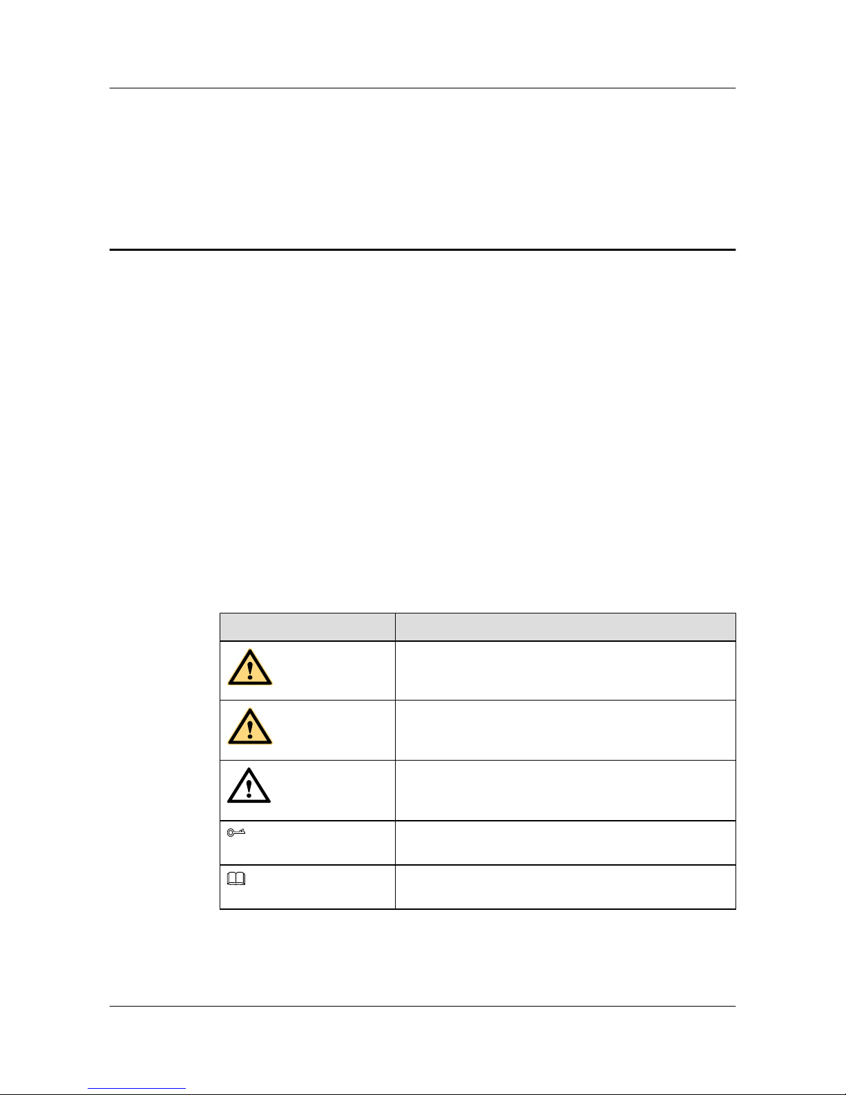
The symbols that may be found in this document are defined as follows.
Symbol
Description
DANGER
Indicates a hazard with a high level of risk, which if not
avoided, will result in death or serious injury.
WARNING
Indicates a hazard with a medium or low level of risk, which
if not avoided, could result in minor or moderate injury.
CAUTION
Indicates a potentially hazardous situation, which if not
avoided, could result in equipment damage, data loss,
performance degradation, or unexpected results.
TIP
Indicates a tip that may help you solve a problem or save
time.
NOTE
Provides additional information to emphasize or supplement
important points of the main text.
S3700&S5700&S6700 Series Ethernet Switches
Quick Start About This Document
Issue 02 (2012-09-10) Huawei Proprietary and Confidential
Copyright © Huawei Technologies Co., Ltd.
ii
Page 4
Command Conventions
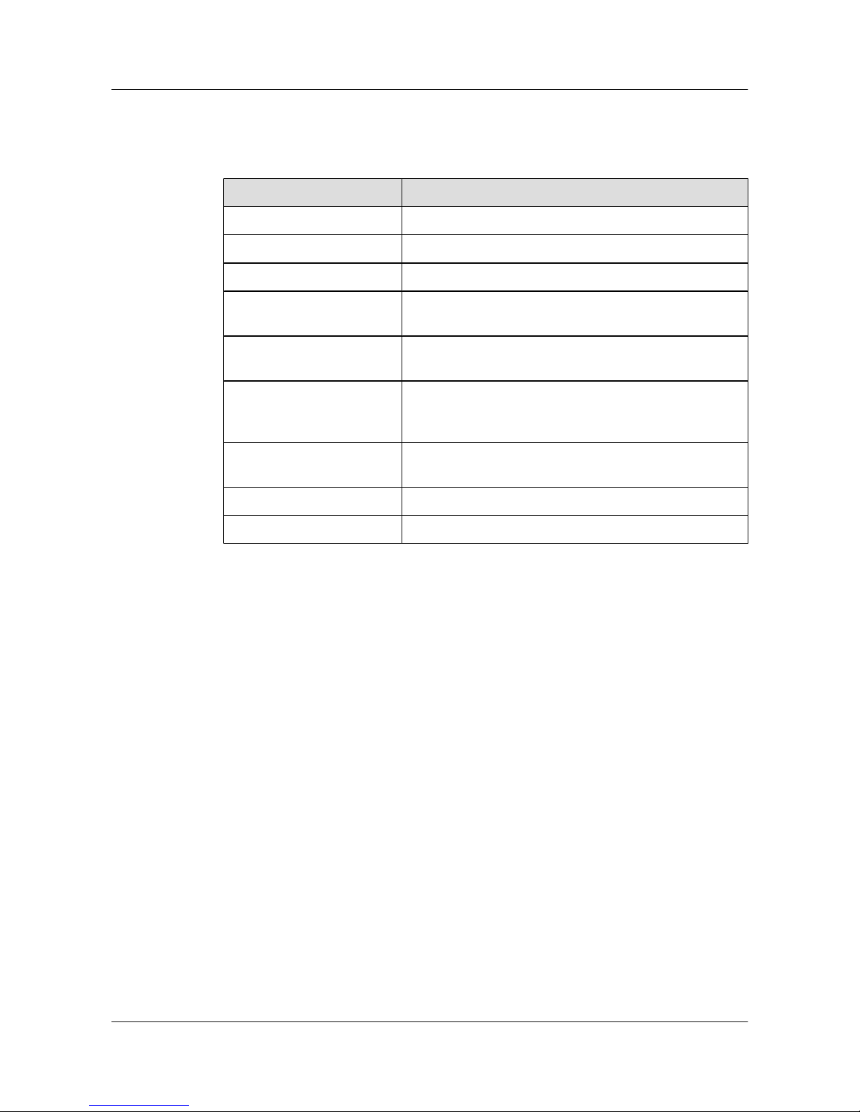
The command conventions that may be found in this document are defined as follows.
Convention Description
Boldface The keywords of a command line are in boldface.
Italic Command arguments are in italics.
[ ] Items (keywords or arguments) in brackets [ ] are optional.
{ x | y | ... } Optional items are grouped in braces and separated by
vertical bars. One item is selected.
[ x | y | ... ] Optional items are grouped in brackets and separated by
vertical bars. One item is selected or no item is selected.
{ x | y | ... }
*
Optional items are grouped in braces and separated by
vertical bars. A minimum of one item or a maximum of all
items can be selected.
[ x | y | ... ]
*
Optional items are grouped in brackets and separated by
vertical bars. Several items or no item can be selected.
&<1-n> The parameter before the & sign can be repeated 1 to n times.
# A line starting with the # sign is comments.
Change History
Updates between document issues are cumulative. Therefore, the latest document issue contains
all changes made in previous issues.
Changes in Issue 02 (2012-09-10)
l Some contents are modified according to updates in the product such as features and
commands.
Changes in Issue 01 (2012-07-25)
Initial commercial release.
S3700&S5700&S6700 Series Ethernet Switches
Quick Start About This Document
Issue 02 (2012-09-10) Huawei Proprietary and Confidential
Copyright © Huawei Technologies Co., Ltd.
iii
Page 5

Contents
About This Document.....................................................................................................................ii
1 Overview.........................................................................................................................................1
2 Product Hardware Introduction..................................................................................................2
2.1 S3700 Introduction.............................................................................................................................................3
2.2 S5700 Introduction.............................................................................................................................................4
2.3 S6700 Introduction.............................................................................................................................................9
2.4 S3700 Indicator Description.............................................................................................................................10
2.5 S5700 Indicator Description.............................................................................................................................13
2.6 S6700 Indicator Description.............................................................................................................................42
3 Device Installation......................................................................................................................47
4 Powering on the Device.............................................................................................................48
4.1 Checking Before Power-on..............................................................................................................................49
4.2 Powering on the Device....................................................................................................................................53
4.3 Checking After Power-on.................................................................................................................................53
5 Logging in to the Device............................................................................................................54
5.1 Logging In to the Switch Through the Console Interface................................................................................55
5.2 Example for Configuring to Manage the SwitchThrough Telnet.....................................................................58
5.3 Logging In to the Web System Client..............................................................................................................61
6 Service Deployment....................................................................................................................63
7 Obtaining Documentation.........................................................................................................64
S3700&S5700&S6700 Series Ethernet Switches
Quick Start Contents
Issue 02 (2012-09-10) Huawei Proprietary and Confidential
Copyright © Huawei Technologies Co., Ltd.
iv
Page 6
1 Overview
This section provides an overview of quick start.
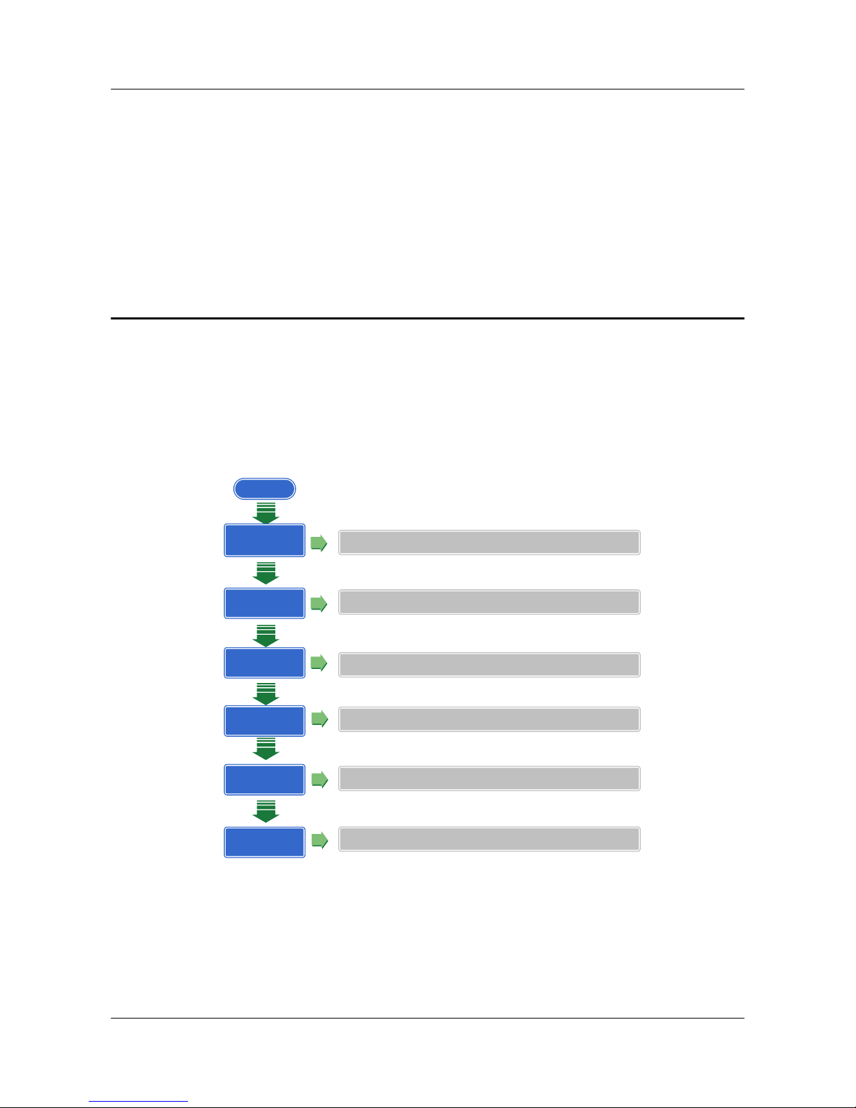
This document helps you quickly learn how to use the S3700/S5700/S6700. Figure 1-1 shows
the quick start contents.
Figure 1-1 Quick start contents
Start
Product Hardware
Introduction
Describes switch models and Indicators on each model
Device Installation
Provides reference for device installation
Powering on the
Device
Logging in to the
Device
Describes precautions to take before and after you power on a switch
Describes how to log in to a switch
Service
Deployment
Provides reference for deploying services on a switch
Obtaining
Documentation
Helps you obtain product documentation quickly
S3700&S5700&S6700 Series Ethernet Switches
Quick Start 1 Overview
Issue 02 (2012-09-10) Huawei Proprietary and Confidential
Copyright © Huawei Technologies Co., Ltd.
1
Page 7

2 Product Hardware Introduction
About This Chapter
This section describes models and indicators of low-end switches.
2.1 S3700 Introduction
This section describes device models and naming rules of the S3700.
2.2 S5700 Introduction
This section describes device models and naming rules of the S5700.
2.3 S6700 Introduction
This section describes device models and naming rules of the S6700.
2.4 S3700 Indicator Description
This section describes the indicators on the S3700 front panel.
2.5 S5700 Indicator Description
This section describes the indicators on the S5700 front panel.
2.6 S6700 Indicator Description
This section describes the indicators on the S6700 front panel.
S3700&S5700&S6700 Series Ethernet Switches
Quick Start 2 Product Hardware Introduction
Issue 02 (2012-09-10) Huawei Proprietary and Confidential
Copyright © Huawei Technologies Co., Ltd.
2
Page 8
2.1 S3700 Introduction
This section describes device models and naming rules of the S3700.
Device Models
Currently, S3700 only has one model, as described in Table 2-1.
Table 2-1 Device models
Model Maximum Number of Interfaces
S3700-26C-HI 26
There are twenty-two 10/100BASE-T Ethernet interfaces,
two GE combo interfaces (10/100/1000BASE-T
+100/1000BASE-X), and two interfaces on the front
subcard.
Naming Rules
Figure 2-1 describes the naming rules of the S3700-26C-HI.
Figure 2-1 Naming rules
S3700-26C-HI
A B C D E
Ide
ntifi
er
Description
A Switch.
B Product series. "37" indicates the S3700 series.
C Maximum number of interfaces.
D Uplink interface type:
l C: A device supports interface cards. There can be two uplink interfaces on an
interface subcard.
E Software version type:
l HI: advanced version, supporting high-performance Operation, Administration,
and Maintenance (OAM) and built-in real-time clock (RTC)
S3700&S5700&S6700 Series Ethernet Switches
Quick Start 2 Product Hardware Introduction
Issue 02 (2012-09-10) Huawei Proprietary and Confidential
Copyright © Huawei Technologies Co., Ltd.
3
Page 9
2.2 S5700 Introduction
This section describes device models and naming rules of the S5700.
Device Models
To meet diverse customer requirements, the S5700 provides a variety of models. Table 2-2 lists
these device models.
You can select a device model as required.
Table 2-2 Device models
Produ
ct
Series
Model Maximum Number of Interfaces
S5700CS5700-28C-EI 28
There are twenty-four 10/100/1000BASE-T Ethernet
interfaces and four interfaces on the front subcard.
S5700-28C-EI-24S 28
There are twenty 100/1000BASE-X Ethernet optical
interfaces, four GE combo interfaces
(10/100/1000BASE-T+100/1000BASE-X), and four
interfaces on the front subcard.
S5700-52C-EI 52
There are forty-eight 10/100/1000BASE-T Ethernet
interfaces and four interfaces on the front subcard.
S5700-28C-PWR-EI 28
There are twenty-four 10/100/1000BASE-T Ethernet
interfaces and four interfaces on the front subcard.
S5700-52C-PWR-EI 52
There are forty-eight 10/100/1000BASE-T Ethernet
interfaces and four interfaces on the front subcard.
S5700-28C-SI 28
There are twenty 10/100/1000BASE-T Ethernet
interfaces, four GE combo interfaces
(10/100/1000BASE-T+100/1000BASE-X), and four
interfaces on the front subcard.
S5700-52C-SI 52
There are forty-eight 10/100/1000BASE-T Ethernet
interfaces and four interfaces on the front subcard.
S3700&S5700&S6700 Series Ethernet Switches
Quick Start 2 Product Hardware Introduction
Issue 02 (2012-09-10) Huawei Proprietary and Confidential
Copyright © Huawei Technologies Co., Ltd.
4
Page 10
Produ
ct
Series
Model Maximum Number of Interfaces
S5700-28C-HI-24S 28
There are twenty-four 100/1000BASE-X Ethernet
optical interfaces and four interfaces on the front
subcard.
S5700-28C-HI 28
There are twenty-four 10/100/1000BASE-T Ethernet
interfaces and four interfaces on the front subcard.
S5700-28C-PWR-SI 28
There are twenty 10/100/1000BASE-T Ethernet
interfaces, four GE combo interfaces
(10/100/1000BASE-T+100/1000BASE-X), and four
interfaces on the front subcard.
S5700-52C-PWR-SI 52
There are forty-eight 10/100/1000BASE-T Ethernet
interfaces and four interfaces on the front subcard.
S5700TPS5700-24TP-SI-AC 24
There are twenty 10/100/1000BASE-T Ethernet
interfaces and four GE combo interfaces
(10/100/1000BASE-T+100/1000BASE-X).
S5700-24TP-SI-DC 24
There are twenty 10/100/1000BASE-T Ethernet
interfaces and four GE combo interfaces
(10/100/1000BASE-T+100/1000BASE-X).
S5700-48TP-SI-AC 48
There are forty-four 10/100/1000BASE-T Ethernet
interfaces and four GE combo interfaces
(10/100/1000BASE-T+100/1000BASE-X).
S5700-48TP-SI-DC 48
There are forty-four 10/100/1000BASE-T Ethernet
interfaces and four GE combo interfaces
(10/100/1000BASE-T+100/1000BASE-X).
S5700-24TP-PWR-SI 24
There are twenty 10/100/1000BASE-T Ethernet
interfaces and four GE combo interfaces
(10/100/1000BASE-T+100/1000BASE-X).
S5700-48TP-PWR-SI 48
There are forty-four 10/100/1000BASE-T Ethernet
interfaces and four GE combo interfaces
(10/100/1000BASE-T+100/1000BASE-X).
S3700&S5700&S6700 Series Ethernet Switches
Quick Start 2 Product Hardware Introduction
Issue 02 (2012-09-10) Huawei Proprietary and Confidential
Copyright © Huawei Technologies Co., Ltd.
5
Page 11
Produ
ct
Series
Model Maximum Number of Interfaces
S5700P S5700-28P-LI-AC 28
There are twenty-four 10/100/1000BASE-T Ethernet
interfaces and four 1000BASE-X Ethernet optical
interfaces.
S5700-28P-LI-DC 28
There are twenty-four 10/100/1000BASE-T Ethernet
interfaces and four 1000BASE-X Ethernet optical
interfaces.
S5700-52P-LI-AC 52
There are forty-eight 10/100/1000BASE-T Ethernet
interfaces and four 1000BASE-X Ethernet optical
interfaces.
S5700-52P-LI-DC 52
There are forty-eight 10/100/1000BASE-T Ethernet
interfaces and four 1000BASE-X Ethernet optical
interfaces.
S5700-28P-PWR-LI-AC 28
There are twenty-four 10/100/1000BASE-T Ethernet
interfaces and four 1000BASE-X Ethernet optical
interfaces.
S5700-52P-PWR-LI-AC 52
There are forty-eight 10/100/1000BASE-T Ethernet
interfaces and four 1000BASE-X Ethernet optical
interfaces.
S5710 S5710-28C-EI 28
There are twenty 10/100/1000BASE-T Ethernet
interfaces, four GE combo interfaces
(10/100/1000BASE-T+100/1000BASE-X), and four
10 Gbit/s SFP+ optical interfaces (working in autosensing mode and changing to GE interfaces).
S5710-52C-EI
52
There are forty-eight 10/100/1000BASE-T Ethernet
interfaces and four 10 Gbit/s SFP+ optical interfaces
(working in auto-sensing mode and changing to GE
interfaces).
S5710-28C-PWR-LI 28
There are twenty 10/100/1000BASE-T Ethernet
interfaces, four GE combo interfaces
(10/100/1000BASE-T+100/1000BASE-X), and four
interfaces on the front subcard.
S3700&S5700&S6700 Series Ethernet Switches
Quick Start 2 Product Hardware Introduction
Issue 02 (2012-09-10) Huawei Proprietary and Confidential
Copyright © Huawei Technologies Co., Ltd.
6
Page 12
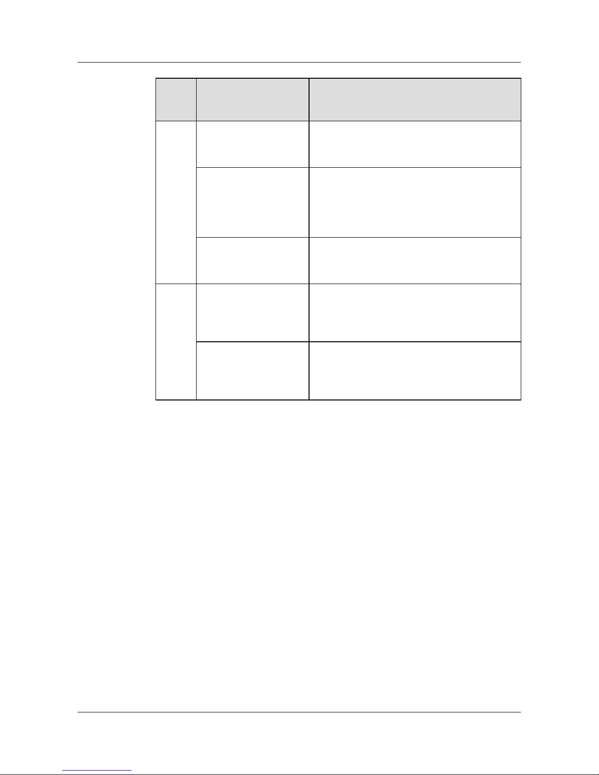
Produ
ct
Series
Model Maximum Number of Interfaces
S5710-52C-PWR-LI 52
There are forty-eight 10/100/1000BASE-T Ethernet
interfaces and four interfaces on the front subcard.
S5710-28C-LI 28
There are twenty 10/100/1000BASE-T Ethernet
interfaces, four GE combo interfaces
(10/100/1000BASE-T+100/1000BASE-X), and four
interfaces on the front subcard.
S5710-52C-LI 52
There are forty-eight 10/100/1000BASE-T Ethernet
interfaces and four interfaces on the front subcard.
S5700S S5700S-28P-LI-AC 28
There are twenty-four 10/100/1000BASE-T Ethernet
interfaces and four 1000BASE-X Ethernet optical
interfaces.
S5700S-52P-LI-AC 52
There are forty-eight 10/100/1000BASE-T Ethernet
interfaces and four 1000BASE-X Ethernet optical
interfaces.
Naming Rules
The following are the naming rules of the S5710-28C-EI, S5700S-52P-LI-AC, S5700-48TPPWR-SI, S5700-28C-EI-24S and S5700-28C-HI.
S3700&S5700&S6700 Series Ethernet Switches
Quick Start 2 Product Hardware Introduction
Issue 02 (2012-09-10) Huawei Proprietary and Confidential
Copyright © Huawei Technologies Co., Ltd.
7
Page 13
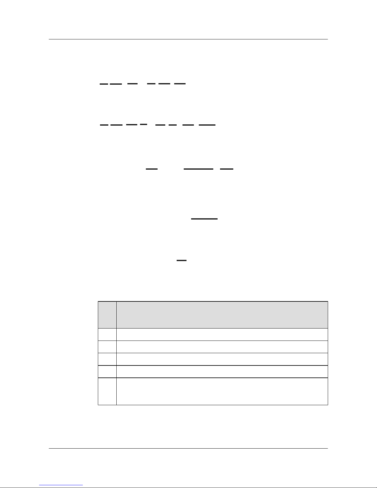
Figure 2-2 Naming rules
S5700-28C-HI
H
S5700-28C-EI-24S
I
S5700-48TP-PWR-SI
E G H
A B
S5710-28C-EI
E F H
C
S5700S-52P-LI-AC
A B E F H J
C
D
Ide
ntifi
er
Description
A Switch.
B Product series. "57" indicates the S5700 series.
C Product subseries.
D The value S indicates business model.
E Maximum number of interfaces.
NOTE
The number of interfaces on an S5700 can be 24, 28, 48, or 52, depending on the device model.
S3700&S5700&S6700 Series Ethernet Switches
Quick Start 2 Product Hardware Introduction
Issue 02 (2012-09-10) Huawei Proprietary and Confidential
Copyright © Huawei Technologies Co., Ltd.
8
Page 14
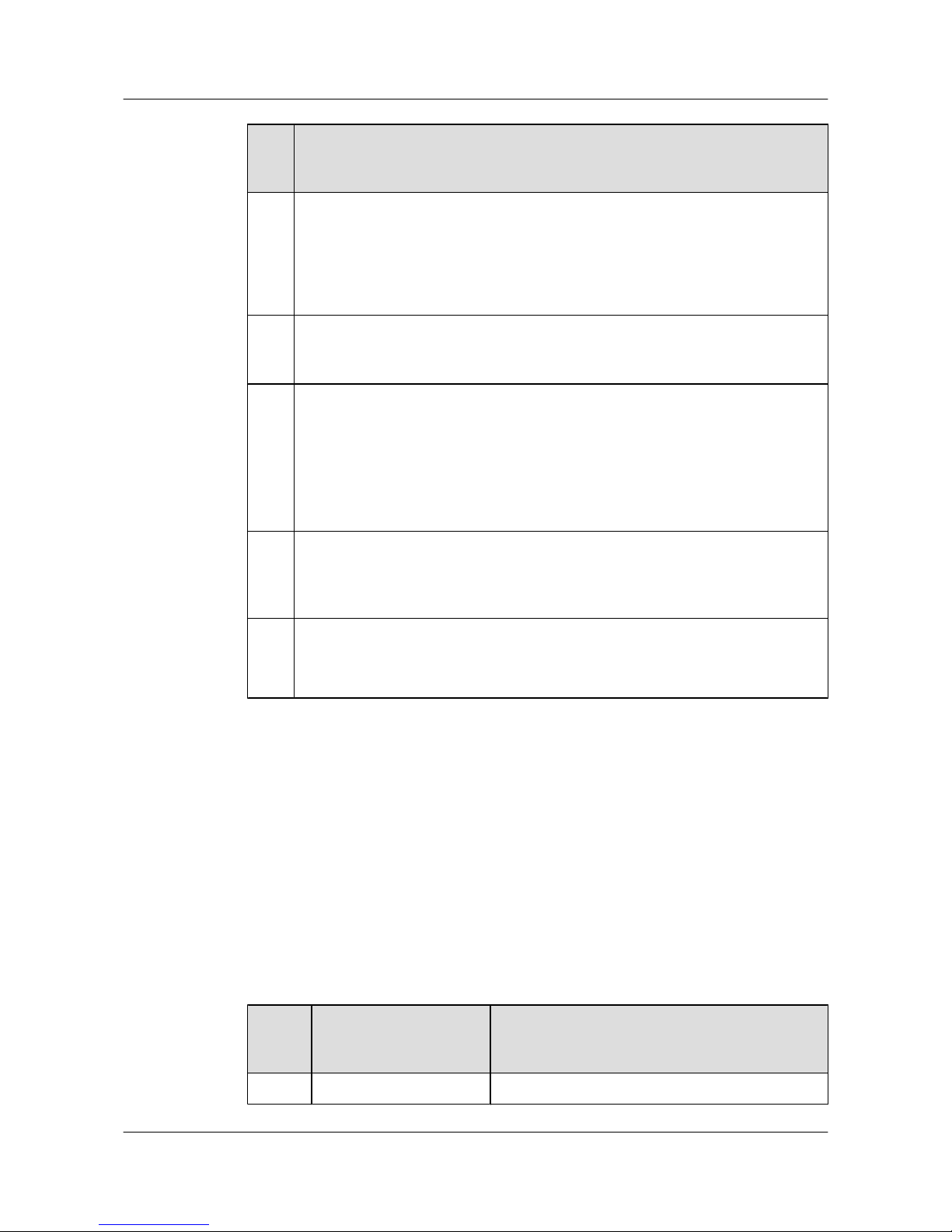
Ide
ntifi
er
Description
F Uplink interface type:
l C: A device supports interface subcards. There can be two, four, or eight uplink
interfaces an interface subcard.
l TP: A device has combo interfaces supporting optical and electrical interfaces.
l P: A device has optical interfaces.
G The S5700 supports Power over Ethernet (PoE).
NOTE
If this letter is not displayed, PoE is not supported.
H Software version type:
l EI: enhanced version, supporting enhanced features.
l SI: standard version, supporting basic features.
l HI: advanced version, supporting high-performance Operation, Administration,
and Maintenance (OAM) and built-in real-time clock (RTC).
l LI: simplified version.
I
Downlink interface type. The value 24S indicates that 24 downlink interfaces of the
S5700-28C-EI-24S are optical interfaces.
NOTE
If this letter is not displayed, all downlink interfaces are electrical interfaces.
J Powering mode:
l AC: alternating current power
l DC: direct current power
2.3 S6700 Introduction
This section describes device models and naming rules of the S6700.
Device Models
To meet diverse customer requirements, the S6700 provides a variety of models. Table 2-3 lists
these device models.
You can select a device model as required.
Table 2-3 Device models
Produ
ct
Series
Model Maximum Number of Interfaces
S6700 S6700-24-EI Twenty-four 10G SFP+ optical interfaces
S3700&S5700&S6700 Series Ethernet Switches
Quick Start 2 Product Hardware Introduction
Issue 02 (2012-09-10) Huawei Proprietary and Confidential
Copyright © Huawei Technologies Co., Ltd.
9
Page 15
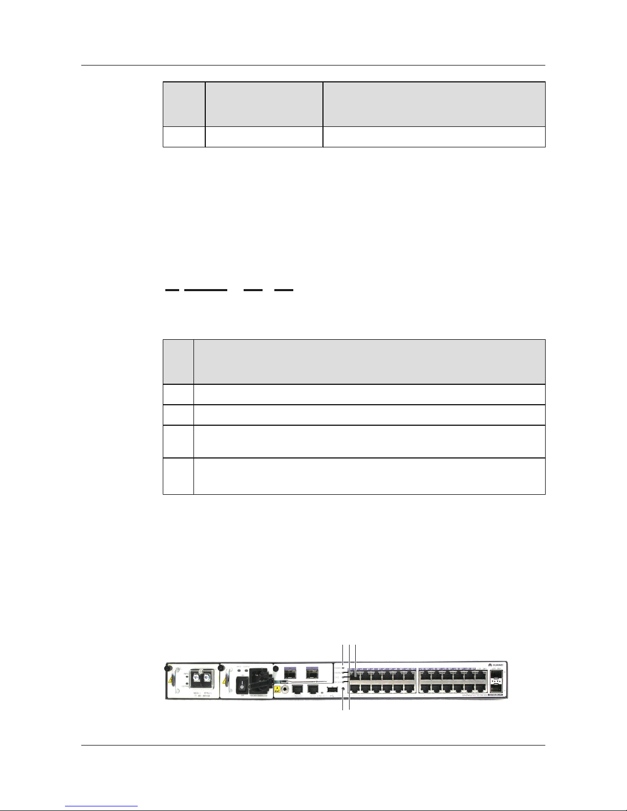
Produ
ct
Series
Model Maximum Number of Interfaces
S6700-48-EI Forty-eight 10G SFP+ optical interfaces
Naming Rules
The following are the naming rules of the S6700-48-EI.
Figure 2-3 Naming rules
S6700-48-EI
A B C D
Ide
ntifi
er
Description
A Switch.
B Product series. "67" indicates the S6700 series.
C Maximum number of interfaces. The number of interfaces on an S6700 can be 24 or
48, depending on the device model.
D Software version type:
l EI: enhanced version, supporting enhanced features
2.4 S3700 Indicator Description
This section describes the indicators on the S3700 front panel.
S3700-26C-HI is a non-PoE switch that supports two power supply units.
Figure 2-4 S3700-26C-HI indicators
2
3
514
S3700&S5700&S6700 Series Ethernet Switches
Quick Start 2 Product Hardware Introduction
Issue 02 (2012-09-10) Huawei Proprietary and Confidential
Copyright © Huawei Technologies Co., Ltd.
10
Page 16
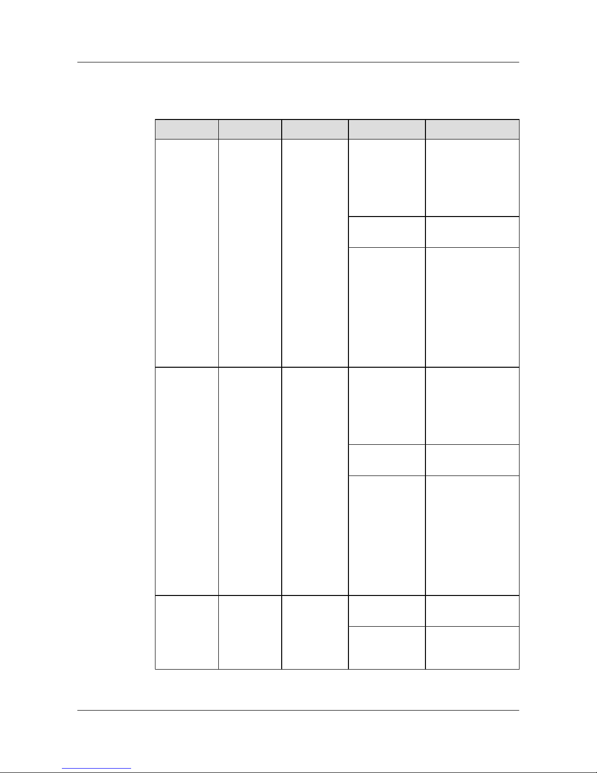
Table 2-4 Description of S3700-26C-HI indicators
No. Indicator Identifier Status Description
1 Power
indicator
PWR1 Off No power supply unit
is installed, or the
power supply is
abnormal when a
single power supply
unit is used.
Green The power supply is
normal.
Red
l Two power supply
units are installed
properly, but not
switched on.
l The power supply
units are switched
off.
l The power supply
units are faulty.
2
Power
indicator
PWR2 Off The power supply
units are not present,
or the power supply is
abnormal when a
single power supply
unit is used.
Green The power supply is
normal.
Red
l Two power supply
units are installed
properly, but not
switched on.
l The power supply
units are switched
off.
l The power supply
units are faulty.
3
System status
indicator
SYS Off The system is not
operating.
Green The system is not
operating properly or
is starting.
S3700&S5700&S6700 Series Ethernet Switches
Quick Start 2 Product Hardware Introduction
Issue 02 (2012-09-10) Huawei Proprietary and Confidential
Copyright © Huawei Technologies Co., Ltd.
11
Page 17
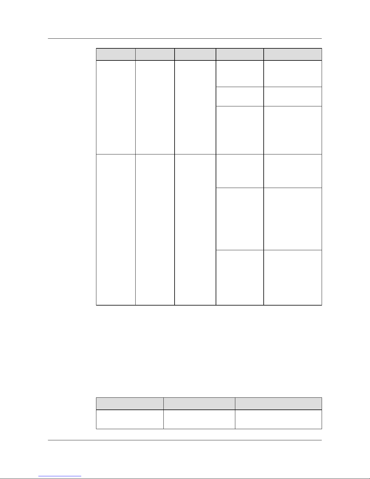
No. Indicator Identifier Status Description
Orange The system is
performing selfcheck during startup.
Blinking green The system is
operating properly.
Red After registering, the
system does not
operate properly, or a
power alarm, fan
alarm, or temperature
alarm is generated.
4 Mode
indicator
MODE Off The service interface
indicator is in the
default mode
(STAT).
Green The service interface
indicator indicates the
interface speed. After
45 seconds, the
service interface
indicator
automatically restores
to off.
Red
The service interface
indicator indicates the
stack ID. After 45
seconds, the service
interface indicator
automatically restores
to off.
As shown in Figure 2-4, the button marked "5" is the mode switching button. When you press
the mode switching button once, the mode indicator turns green and the related interface indicator
enters the speed state. When you press the mode switching button for a second time, the mode
indicator turns red and the related interface indicator represents the stack status. When you press
the mode switching button for a third time, the mode indicator restores to the default state (off).
If you do not press the mode switching button within 45 seconds, the mode indicator
automatically restores to off. The following table describes the meanings of indicators.
Table 2-5 Description of indicators in different modes
Display Mode
Status Description
STAT Off The interface is not connected or
has been shut down.
S3700&S5700&S6700 Series Ethernet Switches
Quick Start 2 Product Hardware Introduction
Issue 02 (2012-09-10) Huawei Proprietary and Confidential
Copyright © Huawei Technologies Co., Ltd.
12
Page 18
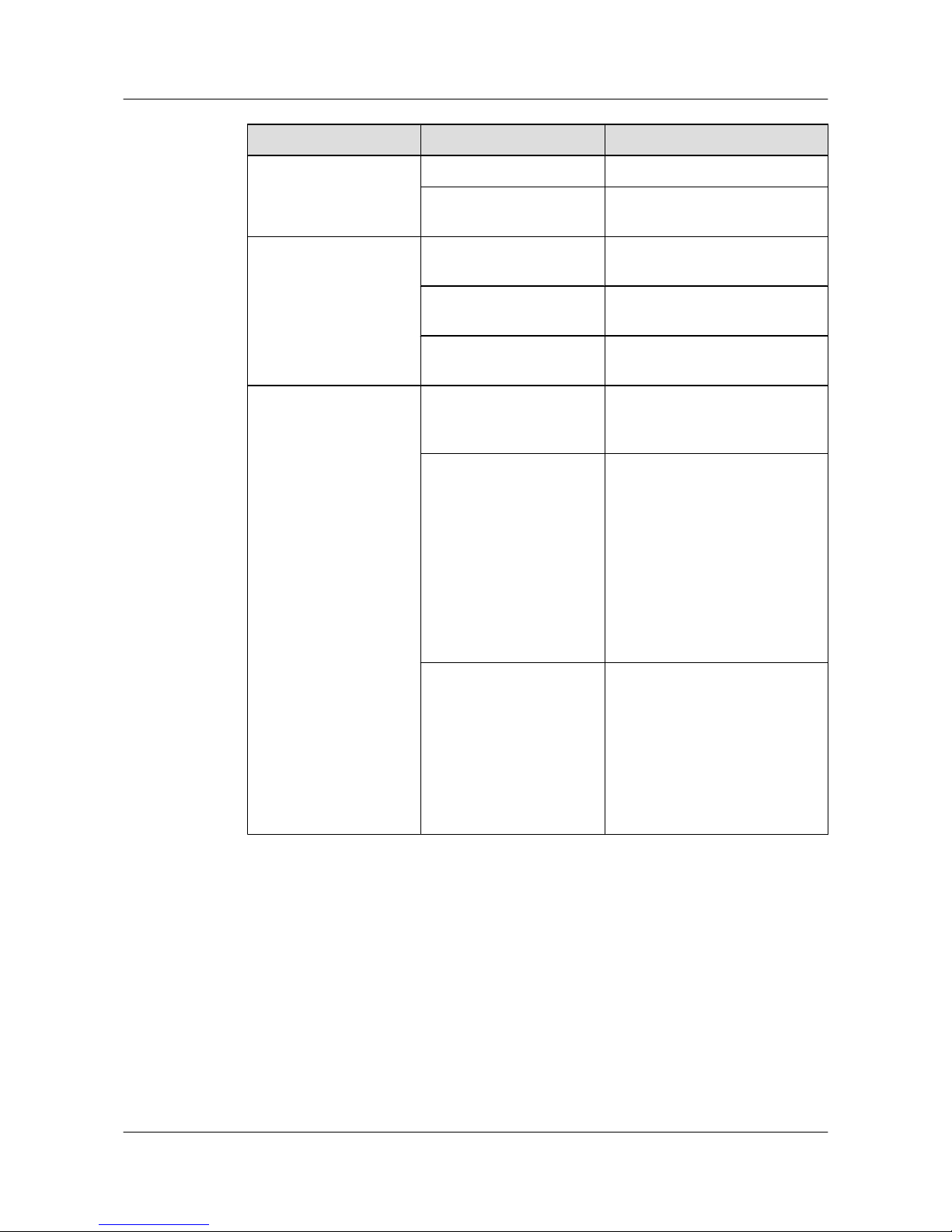
Display Mode Status Description
Green The interface is connected.
Blinking green The interface is sending or
receiving data.
Speed Off The interface is not connected or
has been shut down.
Green The interface is operating at
10/100 Mbit/s.
Blinking green The interface is operating at 1000
Mbit/s.
Stack Off The stack ID of the member
switch is not the number of the
interface in the off state.
Green The device is a not a command
switch:
l If the indicator of an interface
is always on, the number of this
interface is the stack ID of the
device.
l If the first nine interface
indicators of the device are
always on, the stack ID of the
device is 0.
Blinking green
The device is a command switch:
l If the indicator of an interface
blinks, the number of this
interface is the stack ID of the
device.
l If the first nine interface
indicators of the device blink,
the stack ID of the device is 0.
2.5 S5700 Indicator Description
This section describes the indicators on the S5700 front panel.
The indicator meanings of the S5700 vary with models as listed in Table 2-6.
S3700&S5700&S6700 Series Ethernet Switches
Quick Start 2 Product Hardware Introduction
Issue 02 (2012-09-10) Huawei Proprietary and Confidential
Copyright © Huawei Technologies Co., Ltd.
13
Page 19
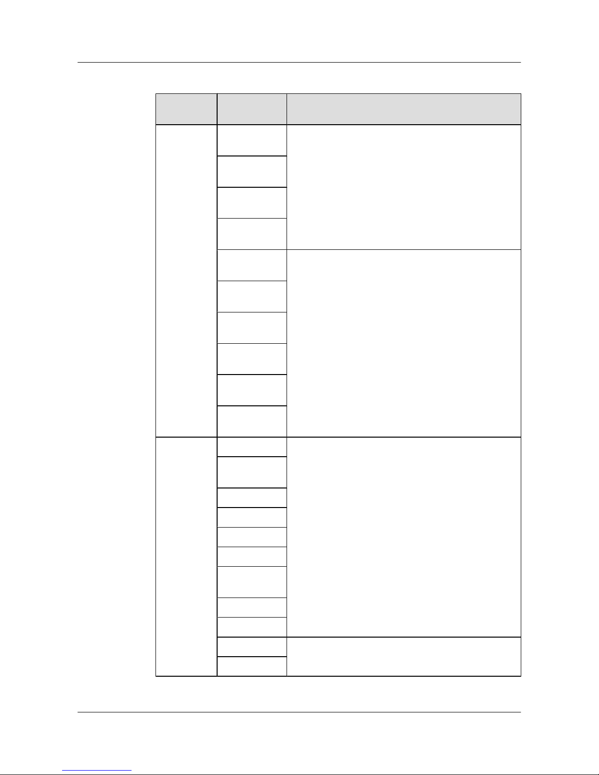
Table 2-6 Indicator meanings and corresponding models
Device
Type
Model Indicator
Non-PoE
switch
supporting a
single power
supply
S5700-24TPSI-AC
Take S5700-24TP-SI-AC for example. See Figure 2-5.
S5700-24TPSI-DC
S5700-48TPSI-AC
S5700-48TPSI-DC
S5700-28P-LI-ACTake S5700-28P-LI-AC for example. See Figure 2-6.
S5700-28P-LIDC
S5700-52P-LIAC
S5700-52P-LIAC
S5700S-28PLI-AC
S5700S-52PLI-AC
Non-PoE
switch
supporting
two power
supplies
S5700-28C-EI Take S5700-28C-EI for example. See Figure 2-7.
S5700-28CEI-24S
S5700-28C-SI
S5700-52C-EI
S5700-52C-SI
S5700-28C-HI
S5700-28CHI-24S
S5710-28C-LI
S5710-52C-LI
S5710-28C-EI Take S5710-28C-EI for example. See Figure 2-8.
S5710-52C-EI
S3700&S5700&S6700 Series Ethernet Switches
Quick Start 2 Product Hardware Introduction
Issue 02 (2012-09-10) Huawei Proprietary and Confidential
Copyright © Huawei Technologies Co., Ltd.
14
Page 20
Device
Type
Model Indicator
PoE switch
supporting
two power
supplies
S5700-28CPWR-EI
Take S5700-28C-PWR-EI for example. See Figure 2-9.
S5700-52CPWR-EI
S5700-24TPPWR-SI
S5700-48TPPWR-SI
S5700-28CPWR-SI
S5700-52CPWR-SI
S5710-28CPWR-LI
S5710-52CPWR-LI
PoE switch
supporting a
single power
supply
S5700-28PPWR-LI-AC
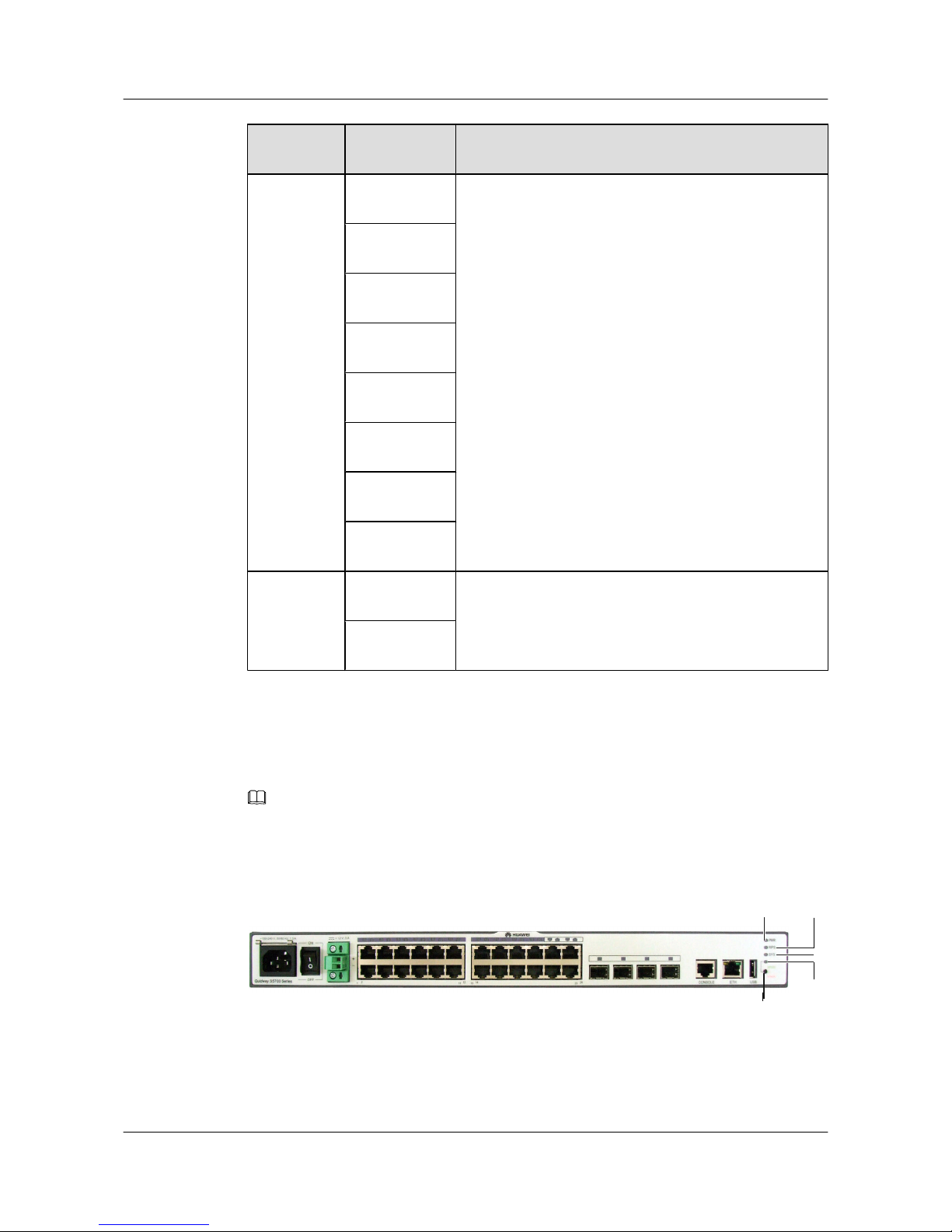
Take S5700-28P-PWR-LI-AC for example. See Figure
2-10.
S5700-52PPWR-LI-AC
Indicators of a Non-PoE S5700
S5700-24TP-SI-AC, and S5700-28P-LI-AC are non-PoE switches.
NOTE
Only S5700-24TP-SI-AC, S5700-24TP-SI-DC, S5700-48TP-SI-AC and S5700-48TP-SI-DC have
redundant power supply (RPS) indicators.
Figure 2-5 S5700-24TP-SI-AC indicators
2
3
4
5
1
S3700&S5700&S6700 Series Ethernet Switches
Quick Start 2 Product Hardware Introduction
Issue 02 (2012-09-10) Huawei Proprietary and Confidential
Copyright © Huawei Technologies Co., Ltd.
15
Page 21
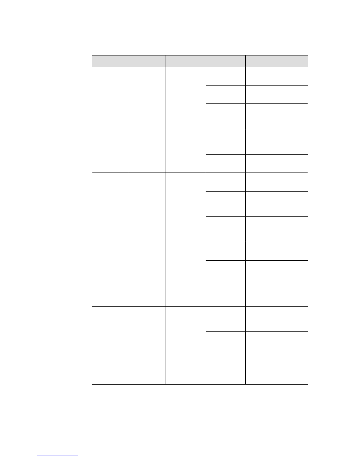
Table 2-7 Description of S5700-24TP-SI-AC indicators
No. Indicator Identifier Status Description
1 Power
indicator
PWR Off The switch is powered
off.
Green The switch is powered
on.
Orange The power supply unit is
faulty, and the external
RPS system has started.
2 RPS
indicator
RPS Off The RPS is not
connected to the switch
or the RPS is faulty.
Green The RPS is connected to
the switch.
3 System status
indicator
SYS Off The system is not
operating.
Green The system is not
operating properly or is
starting.
Orange The system is
performing self-check
during startup.
Blinking green The system is operating
properly.
Red After registering, the
system does not operate
properly, or a power
alarm, fan alarm, or
temperature alarm is
generated.
4 Mode
indicator
- Off The service interface
indicator is in the default
mode (STAT).
Green The service interface
indicator indicates the
interface speed. After 45
seconds, the service
interface indicator
automatically restores to
off.
S3700&S5700&S6700 Series Ethernet Switches
Quick Start 2 Product Hardware Introduction
Issue 02 (2012-09-10) Huawei Proprietary and Confidential
Copyright © Huawei Technologies Co., Ltd.
16
Page 22
No. Indicator Identifier Status Description
Red The service interface
indicator indicates the
stack ID. After 45
seconds, the service
interface indicator
automatically restores to
off.
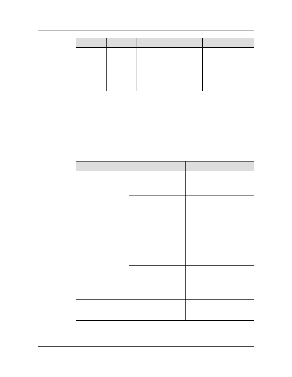
As shown in Figure 2-5, the button marked "5" is the mode switching button. When you press
the mode switching button once, the mode indicator turns green and the related interface indicator
enters the speed state. When you press the mode switching button for a second time, the mode
indicator turns red and the related interface indicator represents the stack status. When you press
the mode switching button for a third time, the mode indicator restores to the default state (off).
If you do not press the mode switching button within 45 seconds, the mode indicator
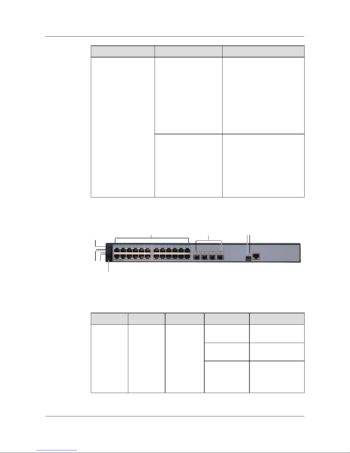
automatically restores to off. The following table describes the meanings of indicators.
Table 2-8 Description of indicators in different modes
Display Mode Status Description
STAT Off The interface is not connected or
has been shut down.
Green The interface is connected.
Blinking green The interface is sending or
receiving data.
Speed Off The interface is not connected or
has been shut down.
Green 10M/100M/1000M interface: The
interface is operating at 10/100
Mbit/s.
1000M/10G interface: The
interface is operating at 1000
Mbit/s.
Blinking green
10M/100M/1000M interface: The
interface is operating at 1000
Mbit/s.
1000M/10G interface: The
interface is operating at 10 Gbit/s.
Stack Off The stack ID of the member
switch is not the number of the
interface in the off state.
S3700&S5700&S6700 Series Ethernet Switches
Quick Start 2 Product Hardware Introduction
Issue 02 (2012-09-10) Huawei Proprietary and Confidential
Copyright © Huawei Technologies Co., Ltd.
17
Page 23
Display Mode Status Description
Green The device is a not a command
switch:
l If the indicator of an interface
is steady on, the number of this
interface is the stack ID of the
device.
l If the first nine interface
indicators of the device are
steady on, the stack ID of the
device is 0.
Blinking green
The device is a command switch:
l If the indicator of an interface
blinks, the number of this
interface is the stack ID of the
device.
l If the first nine interface
indicators of the device blink,
the stack ID of the device is 0.
Figure 2-6 S5700-28P-LI-AC indicators
1
2
4
3
5
6
7
7
8
9
Table 2-9 Description of S5700-28P-LI-AC indicators
No.
Indicator Identifier Status Description
1 Power
indicator
PWR Off The switch is
powered off.
Green The switch is
powered on.
Orange The power supply
unit is faulty, and the
external RPS system
has started.
S3700&S5700&S6700 Series Ethernet Switches
Quick Start 2 Product Hardware Introduction
Issue 02 (2012-09-10) Huawei Proprietary and Confidential
Copyright © Huawei Technologies Co., Ltd.
18
Page 24
No. Indicator Identifier Status Description
2 System status
indicator
SYS Off The system is not
operating.
Blinking green
quickly (4 Hz)
The system is starting.
Blinking green
slowly (0.5 Hz)
The system is
operating properly.
Blinking orange
(0.5 Hz)
The system is
sleeping.
NOTE
When the switch is
sleeping, pressing the
MODE button can
waken the switch.
Red
The system does not
operate properly, or a
power alarm, fan
alarm is generated.
3 STAT
indicator
STAT Off The indicator is not in
the STAT mode.
Green The service interface
indicator is in the
default mode
(STAT).
4 Speed
indicator
SPED Off The indicator is not in
the speed mode.
Green The service interface
indicator indicates the
interface speed. After
45 seconds, the
service interface
indicator
automatically restores
to STAT.
5
Stack
indicator
STCK Off The indicator is not in
the stack mode.
Green The service interface
indicator indicates the
stack information.
After 45 seconds, the
service interface
indicator
automatically restores
to STAT.
S3700&S5700&S6700 Series Ethernet Switches
Quick Start 2 Product Hardware Introduction
Issue 02 (2012-09-10) Huawei Proprietary and Confidential
Copyright © Huawei Technologies Co., Ltd.
19
Page 25
No. Indicator Identifier Status Description
Blinking green The indicator
indicates the active
device in a stack or a
device not added to a
stack.
6 Mode
switching
button
MODE -
l When you press
the button once,
the SPED
indicator turns
green and the
service interface
indicators show
the speed status of
interfaces.
l When you press
the button for a
second time, the
STCK indicator
turns green and the
service interface
indicators show
the stack status.
l When you press
the button for a
third time, the
STAT indicator
turns green.
If you do not press the
button within 45
seconds, the
indicators restore to
the default status.
That is, the STAT
indicator turns green,
and the SPED and
STCK indicators are
off.
S3700&S5700&S6700 Series Ethernet Switches
Quick Start 2 Product Hardware Introduction
Issue 02 (2012-09-10) Huawei Proprietary and Confidential
Copyright © Huawei Technologies Co., Ltd.
20
Page 26
No. Indicator Identifier Status Description
7 Service
interface
indicator
l GE
electrical
interfaces:
The first
indicator
shows the
status of
the bottom
left
interface.
The
indicators
correspond
to the
interfaces
from
bottom to
top and
from left to
right.
l GE optical
interfaces:
Each
optical
interface
has a
correspond
ing
indicator
above it.
Off
Green
Blinking green
The meanings of
service interface
indicators vary
according to the
indicator status. For
details, see Table
2-10.
8
Mini USB
indicator
The indicators
for the Mini
USB port and
CON port are
close to each
other. The
Mini USB
indicator has
an arrowhead
pointing to the
Mini USB
port.
Off
The Mini USB port is
not in use.
Green The Mini USB port is
in use.
9 CON
indicator
The indicators
for the Mini
USB port and
CON port are
close to each
other. The
CON indicator
Off
The Mini USB port is
in use.
S3700&S5700&S6700 Series Ethernet Switches
Quick Start 2 Product Hardware Introduction
Issue 02 (2012-09-10) Huawei Proprietary and Confidential
Copyright © Huawei Technologies Co., Ltd.
21
Page 27
No. Indicator Identifier Status Description
has an
arrowhead
pointing to the
CON port.
Green The Mini USB port is
not in use. This
indicator is steady
green unless the Mini
USB port is accessed.
Table 2-10 Description of service interface indicators in different modes
Display Mode Status Description
STAT Off The interface is not connected or
has been shut down.
Green The interface is connected.
Blinking green The interface is sending or
receiving data.
Speed Off The interface is not connected or
has been shut down.
Green 10M/100M/1000M interface: The
interface is operating at 10/100
Mbit/s.
1000M/10G interface: The
interface is operating at 1000
Mbit/s.
Blinking green
10M/100M/1000M interface: The
interface is operating at 1000
Mbit/s.
1000M/10G interface: The
interface is operating at 10 Gbit/s.
Stack Off The stack ID of the member
switch is not the number of the
interface in the off state.
Green The device is a not a command
switch:
l If the indicator of an interface
is steady on, the number of this
interface is the stack ID of the
device.
l If the first nine interface
indicators of the device are
steady on, the stack ID of the
device is 0.
S3700&S5700&S6700 Series Ethernet Switches
Quick Start 2 Product Hardware Introduction
Issue 02 (2012-09-10) Huawei Proprietary and Confidential
Copyright © Huawei Technologies Co., Ltd.
22
Page 28
Display Mode Status Description
Blinking green The device is a command switch:
l If the indicator of an interface
blinks, the number of this
interface is the stack ID of the
device.
l If the first nine interface
indicators of the device blink,
the stack ID of the device is 0.
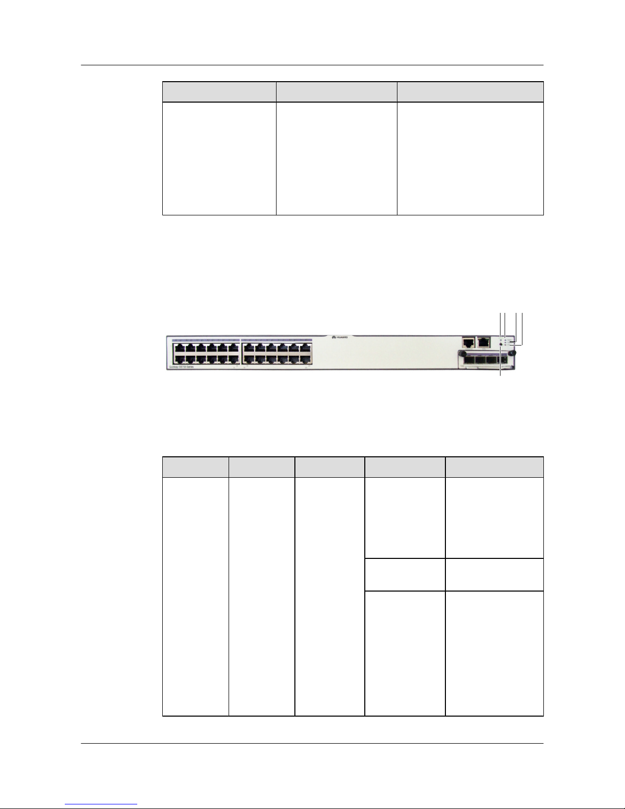
The S5700-28C-EI and S5710-28C-EI are non-PoE switches with dual power supply units.
Figure 2-7 S5700-28C-EI indicators
2
3
5
14
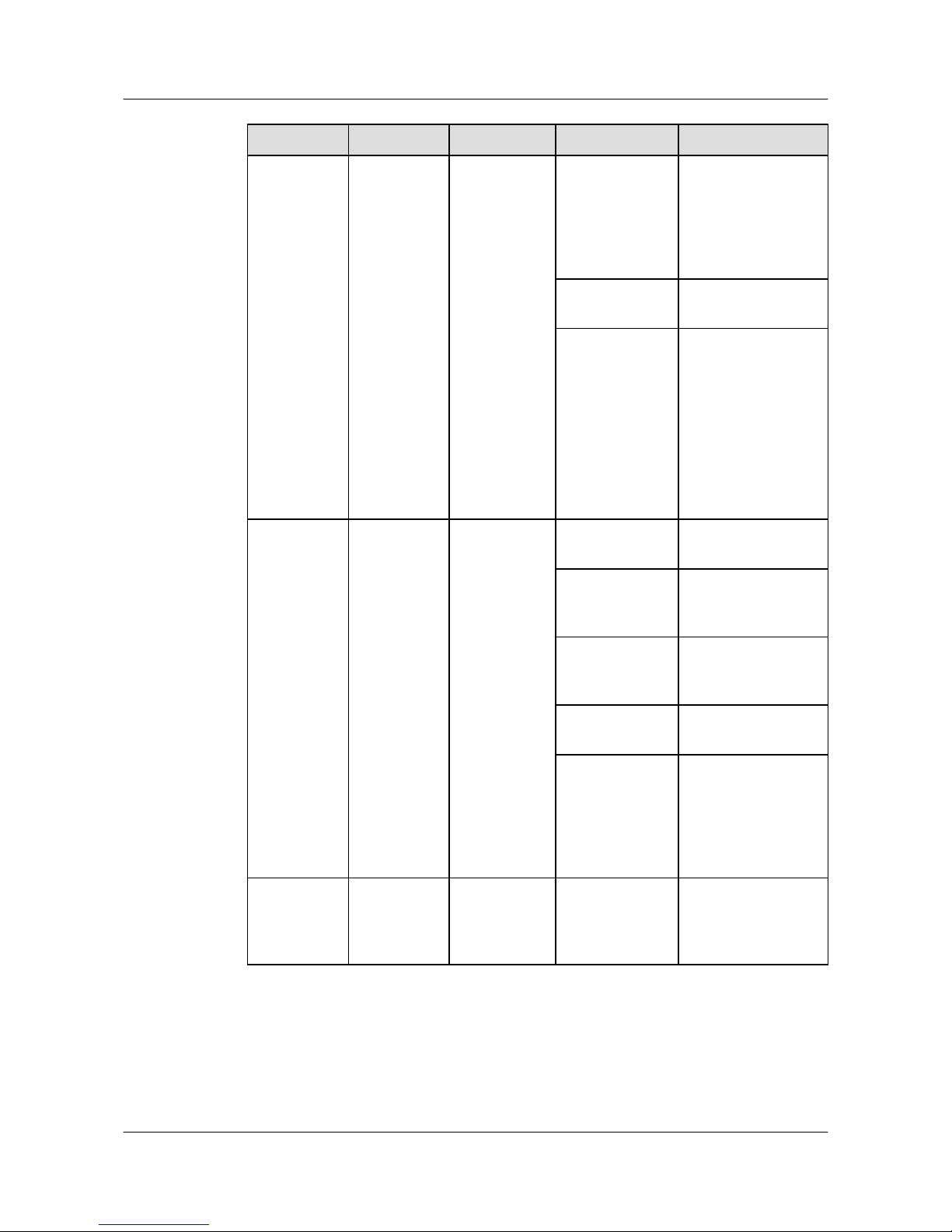
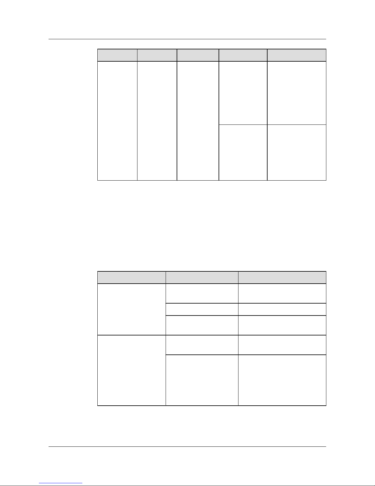
Table 2-11 Description of S5700-28C-EI indicators
No.
Indicator Identifier Status Description
1 Power
indicator
PWR1 Off The power supply
units are not present,
or the power supply is
abnormal when a
single power supply
unit is used.
Green The power supply is
normal.
Red
l Two power supply
units are installed
properly, but not
switched on.
l The power supply
units are switched
off.
l The power supply
units are faulty.
S3700&S5700&S6700 Series Ethernet Switches
Quick Start 2 Product Hardware Introduction
Issue 02 (2012-09-10) Huawei Proprietary and Confidential
Copyright © Huawei Technologies Co., Ltd.
23
Page 29
No. Indicator Identifier Status Description
2 Power
indicator
PWR2 Off The power supply
units are not present,
or the power supply is
abnormal when a
single power supply
unit is used.
Green The power supply is
normal.
Red
l Two power supply
units are installed
properly, but not
switched on.
l The power supply
units are switched
off.
l The power supply
units are faulty.
3
System status
indicator
SYS Off The system is not
operating.
Green The system is not
operating properly or
is starting.
Orange The system is
performing selfcheck during startup.
Blinking green The system is
operating properly.
Red After registering, the
system does not
operate properly, or a
power alarm, fan
alarm, or temperature
alarm is generated.
4 Mode
indicator
MODE Off The service interface
indicator is in the
default mode
(STAT).
S3700&S5700&S6700 Series Ethernet Switches
Quick Start 2 Product Hardware Introduction
Issue 02 (2012-09-10) Huawei Proprietary and Confidential
Copyright © Huawei Technologies Co., Ltd.
24
Page 30
No. Indicator Identifier Status Description
Green The service interface
indicator indicates the
interface speed. After
45 seconds, the
service interface
indicator
automatically restores
to off.
Red
The service interface
indicator indicates the
stack ID. After 45
seconds, the service
interface indicator
automatically restores
to off.
As shown in Figure 2-7, the button marked "5" is the mode switching button. When you press
the mode switching button once, the mode indicator turns green and the related interface indicator
enters the speed state. When you press the mode switching button for a second time, the mode
indicator turns red and the related interface indicator represents the stack status. When you press
the mode switching button for a third time, the mode indicator restores to the default state (off).
If you do not press the mode switching button within 45 seconds, the mode indicator
automatically restores to off. The following table describes the meanings of indicators.
Table 2-12 Description of indicators in different modes
Display Mode
Status Description
STAT Off The interface is not connected or
has been shut down.
Green The interface is connected.
Blinking green The interface is sending or
receiving data.
Speed Off The interface is not connected or
has been shut down.
Green 10M/100M/1000M interface: The
interface is operating at 10/100
Mbit/s.
1000M/10G interface: The
interface is operating at 1000
Mbit/s.
S3700&S5700&S6700 Series Ethernet Switches
Quick Start 2 Product Hardware Introduction
Issue 02 (2012-09-10) Huawei Proprietary and Confidential
Copyright © Huawei Technologies Co., Ltd.
25
Page 31
Display Mode Status Description
Blinking green 10M/100M/1000M interface: The
interface is operating at 1000
Mbit/s.
1000M/10G interface: The
interface is operating at 10 Gbit/s.
Stack Off The stack ID of the member
switch is not the number of the
interface in the off state.
Green The device is a not a command
switch:
l If the indicator of an interface
is steady on, the number of this
interface is the stack ID of the
device.
l If the first nine interface
indicators of the device are
steady on, the stack ID of the
device is 0.
Blinking green
The device is a command switch:
l If the indicator of an interface
blinks, the number of this
interface is the stack ID of the
device.
l If the first nine interface
indicators of the device blink,
the stack ID of the device is 0.
Figure 2-8 S5710-28C-EI indicators
1
2
4
3 56
7
8
8
9
1011
8
S3700&S5700&S6700 Series Ethernet Switches
Quick Start 2 Product Hardware Introduction
Issue 02 (2012-09-10) Huawei Proprietary and Confidential
Copyright © Huawei Technologies Co., Ltd.
26
Page 32
Table 2-13 Description of S5710-28C-EI indicators
No. Indicator Identifier Status Description
1 From the rear
view: power
indicator on
the right
PWR1 Off The power supply
units are not present,
or the power supply is
abnormal when a
single power supply
unit is used.
Green The switch is
powered on.
Orange Possible causes are as
follows:
l Two power supply
units are installed,
but not switched
on.
l The power supply
units are not
connected
properly.
l A power supply
unit is faulty.
2
From the rear
view: power
indicator on
the left
PWR2 Off The power supply
units are not present,
or the power supply is
abnormal when a
single power supply
unit is used.
Green The switch is
powered on.
Orange Possible causes are as
follows:
l Two power supply
units are installed,
but not switched
on.
l The power supply
units are not
connected
properly.
l A power supply
unit is faulty.
3
System status
indicator
SYS Off The system is not
operating.
S3700&S5700&S6700 Series Ethernet Switches
Quick Start 2 Product Hardware Introduction
Issue 02 (2012-09-10) Huawei Proprietary and Confidential
Copyright © Huawei Technologies Co., Ltd.
27
Page 33
No. Indicator Identifier Status Description
Blinking green
quickly (4 Hz)
The system is starting.
Blinking green
slowly (0.5 Hz)
The system is
operating properly.
Blinking orange
(0.5 Hz)
The system is
sleeping.
Red The system does not
operate properly, or a
power alarm, fan
alarm is generated.
4 STAT
indicator
STAT Off The indicator is not in
the STAT mode.
Green The service interface
indicator is in the
default mode
(STAT).
5 Speed
indicator
SPED Off The indicator is not in
the speed mode.
Green The service interface
indicator indicates the
interface speed. After
45 seconds, the
service interface
indicator
automatically restores
to STAT.
6
Stack
indicator
STCK Off The indicator is not in
the stack mode.
Green The service interface
indicator indicates the
stack information.
After 45 seconds, the
service interface
indicator
automatically restores
to STAT.
Blinking green
The indicator
indicates the active
device in a stack or a
device not added to a
stack.
S3700&S5700&S6700 Series Ethernet Switches
Quick Start 2 Product Hardware Introduction
Issue 02 (2012-09-10) Huawei Proprietary and Confidential
Copyright © Huawei Technologies Co., Ltd.
28
Page 34
No. Indicator Identifier Status Description
7 Mode
switching
button
MODE -
l When you press
the button once,
the SPED
indicator turns
green and the
service interface
indicators show
the speed status of
interfaces.
l When you press
the button for a
second time, the
STCK indicator
turns green and the
service interface
indicators show
the stack status.
l When you press
the button for a
third time, the
STAT indicator
turns green.
If you do not press the
button within 45
seconds, the
indicators restore to
the default status.
That is, the STAT
indicator turns green,
and the SPED and
STCK indicators are
off.
S3700&S5700&S6700 Series Ethernet Switches
Quick Start 2 Product Hardware Introduction
Issue 02 (2012-09-10) Huawei Proprietary and Confidential
Copyright © Huawei Technologies Co., Ltd.
29
Page 35
No. Indicator Identifier Status Description
8 Service
interface
indicator
l GE
electrical
interfaces:
The first
indicator
shows the
status of
the bottom
left
interface.
The
indicators
correspond
to the
interfaces
from
bottom to
top and
from left to
right.
l GE optical
interfaces:
Each
optical
interface
has a
correspond
ing
indicator
above it.
Off
Green
Blinking green
The meanings of
service interface
indicators vary
according to the
indicator status. For
details, see Table
2-14.
9
Mini USB
indicator
The indicators
for the Mini
USB port,
CON port, and
ETH port are
close to each
other. The
Mini USB
indicator has
an arrowhead
pointing to the
Mini USB
port.
Off
The Mini USB port is
not in use.
Green The Mini USB port is
in use.
10 CON
indicator
The indicators
for the Mini
USB port,
CON port, and
ETH port are
close to each
Off The Mini USB port is
in use.
S3700&S5700&S6700 Series Ethernet Switches
Quick Start 2 Product Hardware Introduction
Issue 02 (2012-09-10) Huawei Proprietary and Confidential
Copyright © Huawei Technologies Co., Ltd.
30
Page 36
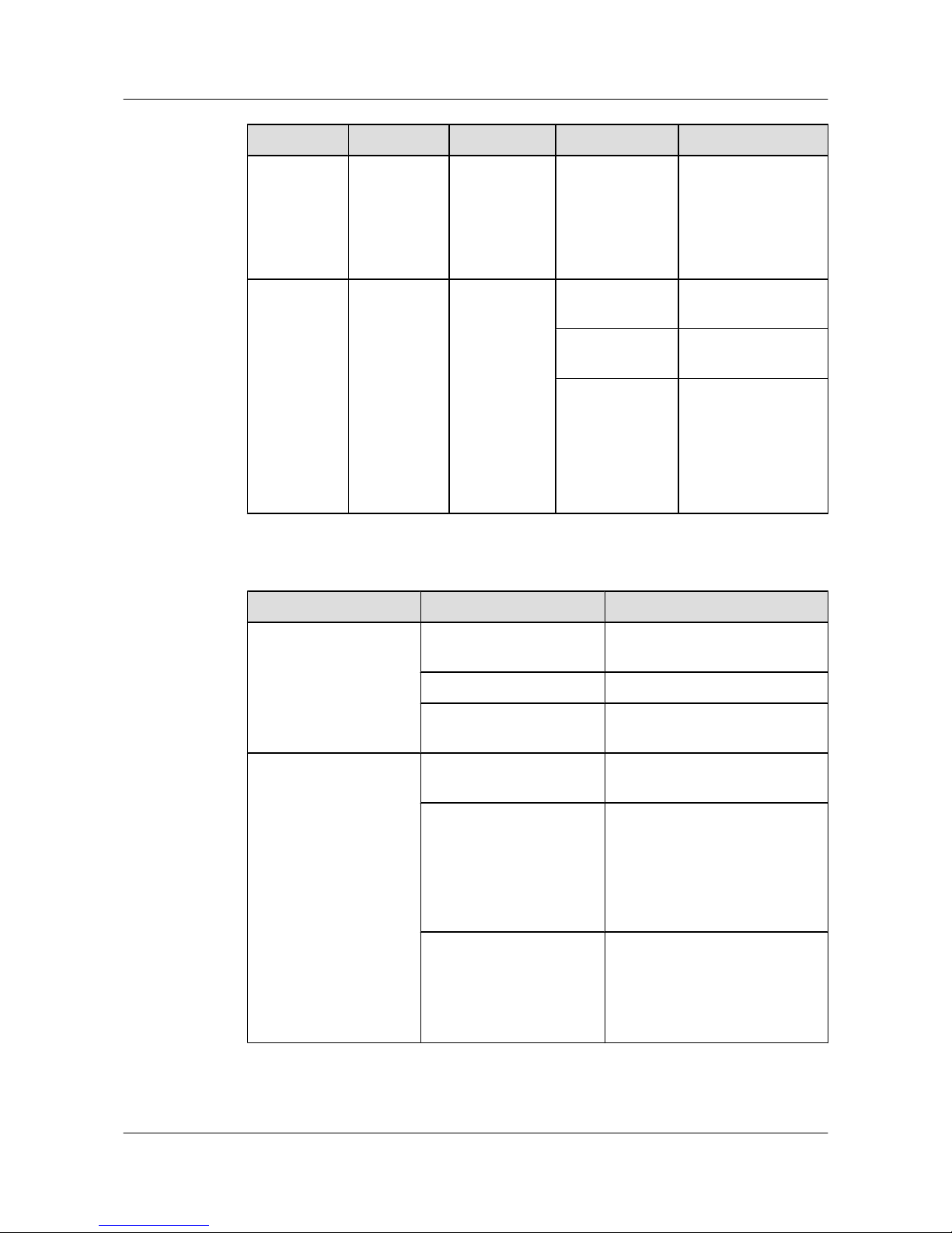
No. Indicator Identifier Status Description
other. The
CON indicator
has an
arrowhead
pointing to the
CON port.
Green The Mini USB port is
not in use. This
indicator is steady
green unless the Mini
USB port is accessed.
11 ETH
indicator
The indicators
for the Mini
USB port,
CON port, and
ETH port are
close to each
other. The
ETH indicator
has an
arrowhead
pointing to the
ETH port.
Off
The interface is not
connected.
Green The interface is
connected.
Blinking green The interface is
sending or receiving
data.
Table 2-14 Description of service interface indicators in different modes
Display Mode
Status Description
STAT Off The interface is not connected or
has been shut down.
Green The interface is connected.
Blinking green The interface is sending or
receiving data.
Speed Off The interface is not connected or
has been shut down.
Green 10M/100M/1000M interface: The
interface is operating at 10/100
Mbit/s.
1000M/10G interface: The
interface is operating at 1000
Mbit/s.
Blinking green
10M/100M/1000M interface: The
interface is operating at 1000
Mbit/s.
1000M/10G interface: The
interface is operating at 10 Gbit/s.
S3700&S5700&S6700 Series Ethernet Switches
Quick Start 2 Product Hardware Introduction
Issue 02 (2012-09-10) Huawei Proprietary and Confidential
Copyright © Huawei Technologies Co., Ltd.
31
Page 37
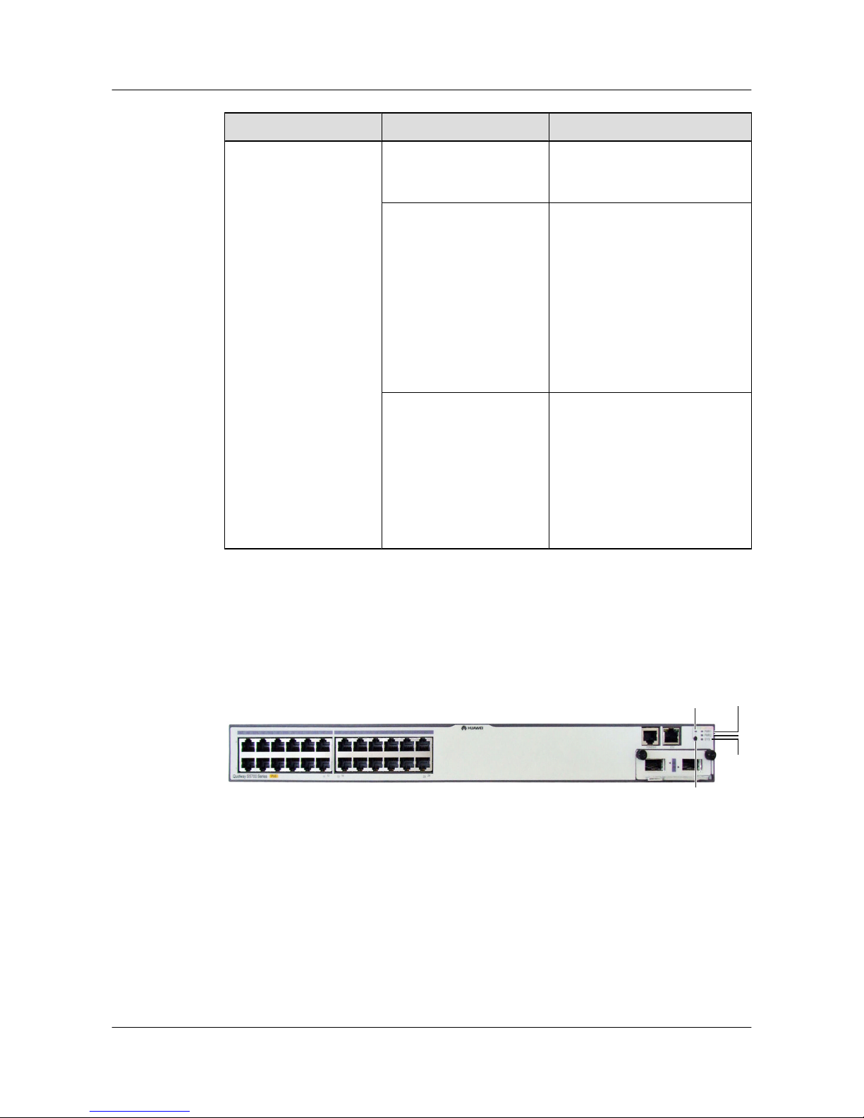
Display Mode Status Description
Stack Off The stack ID of the member
switch is not the number of the
interface in the off state.
Green The device is a not a command
switch:
l If the indicator of an interface
is steady on, the number of this
interface is the stack ID of the
device.
l If the first nine interface
indicators of the device are
steady on, the stack ID of the
device is 0.
Blinking green
The device is a command switch:
l If the indicator of an interface
blinks, the number of this
interface is the stack ID of the
device.
l If the first nine interface
indicators of the device blink,
the stack ID of the device is 0.
Indicators of a PoE S5700
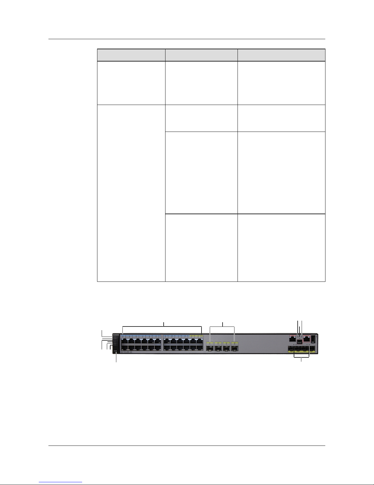
The S5700-28C-PWR-EI and S5700-28P-PWR-LI-AC are PoE switches.
Figure 2-9 S5700-28C-PWR-EI indicators
1
2
3
5
4
S3700&S5700&S6700 Series Ethernet Switches
Quick Start 2 Product Hardware Introduction
Issue 02 (2012-09-10) Huawei Proprietary and Confidential
Copyright © Huawei Technologies Co., Ltd.
32
Page 38
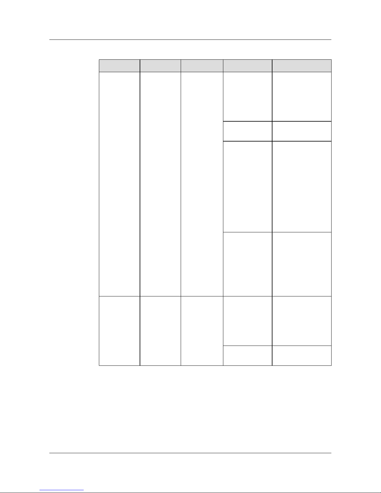
Table 2-15 Description of S5700-28C-PWR-EI indicators
No. Indicator Identifier Status Description
1 Power
indicator
PWR1 Off The power supply
units are not present,
or the power supply is
abnormal when a
single power supply
unit is used.
Green The power supply is
normal.
Red
l Two power
supply units are
installed properly,
but not switched
on.
l The power supply
units are switched
off.
l The card power
and PoE power
are abnormal.
Orange
If a single power
supply unit is
installed, the PoE
power is out of range.
If two power supply
units are installed, the
card power or PoE
power is out of range.
2
Power
indicator
PWR2 Off The power supply
units are not present,
or the power supply is
abnormal when a
single power supply
unit is used.
Green The power supply is
normal.
S3700&S5700&S6700 Series Ethernet Switches
Quick Start 2 Product Hardware Introduction
Issue 02 (2012-09-10) Huawei Proprietary and Confidential
Copyright © Huawei Technologies Co., Ltd.
33
Page 39
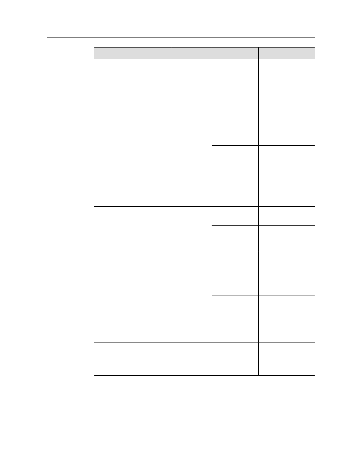
No. Indicator Identifier Status Description
Red
l Two power
supply units are
installed properly,
but not switched
on.
l The power supply
units are switched
off.
l The card power
and PoE power
are abnormal.
Orange
If a single power
supply unit is
installed, the PoE
power is out of range.
If two power supply
units are installed, the
card power or PoE
power is out of range.
3
System status
indicator
SYS Off The system is not
operating.
Green The system is not
operating properly or
is starting.
Orange The system is
performing selfcheck during startup.
Blinking green The system is
operating properly.
Red After registering, the
system does not
operate properly, or a
power alarm, fan
alarm, or temperature
alarm is generated.
4 Mode
indicator
- Off The service interface
indicator is in the
default mode
(STAT).
S3700&S5700&S6700 Series Ethernet Switches
Quick Start 2 Product Hardware Introduction
Issue 02 (2012-09-10) Huawei Proprietary and Confidential
Copyright © Huawei Technologies Co., Ltd.
34
Page 40
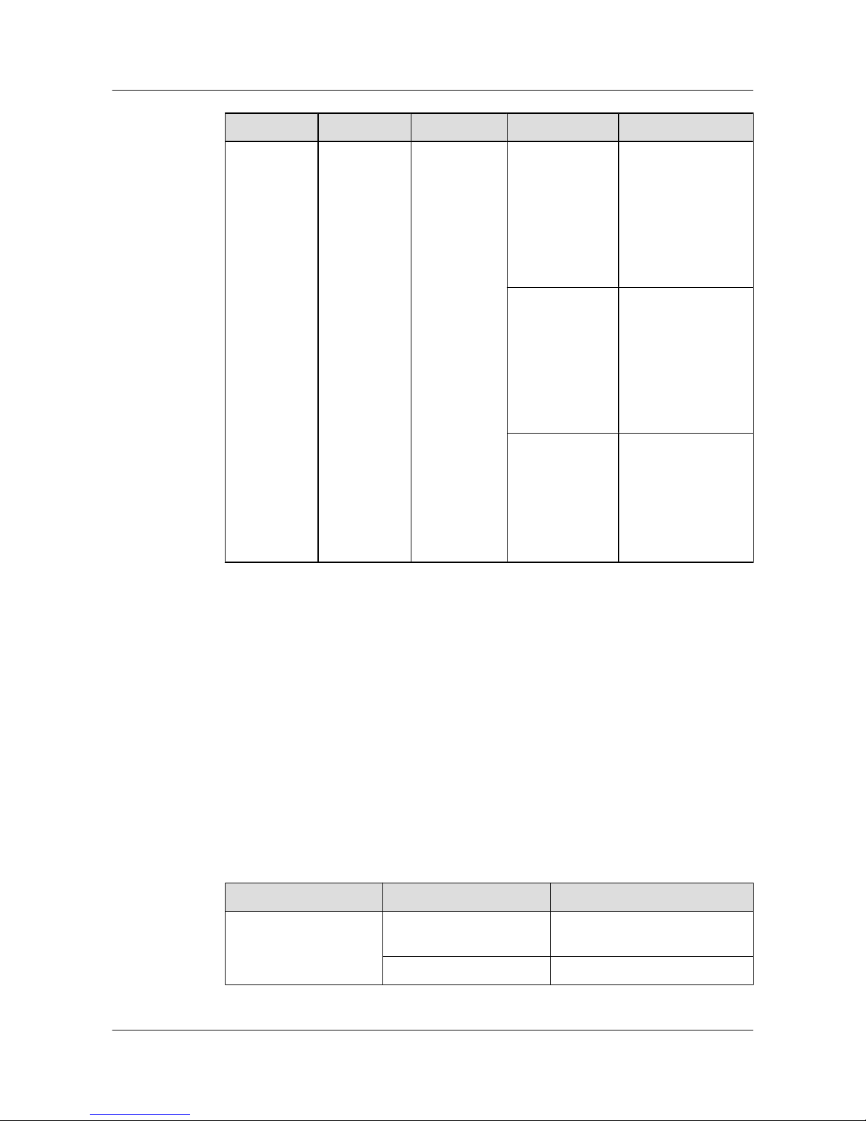
No. Indicator Identifier Status Description
Green The service interface
indicator indicates
the interface speed.
After 45 seconds, the
service interface
indicator
automatically
restores to off.
Orange
The service interface
indicator indicates
the PoE status. After
45 seconds, the
service interface
indicator
automatically
restores to off.
Red
The service interface
indicator indicates
the stack ID. After 45
seconds, the service
interface indicator
automatically
restores to off.
As shown in Figure 2-9, the button marked "5" is the mode switching button. On an S5700, you
can press the mode switching button to switch the display modes of interface indicators. The
status of a mode indicator represents the display mode of the related interface indicator. For
example, the mode indicator of S5700-28C-PWR-EI is off and the interface indicators are in
STAT state by default. When you press the mode switching button once, the mode indicator
turns green and the related interface indicator enters the speed state. When you press the mode
switching button for a second time, the mode indicator turns orange and the related interface
indicator represents the PoE power status. When you press the mode switching button for a third
time, the mode indicator turns red and the related interface indicator represents the stack status.
When you press the mode switching button for a fourth time, the mode indicator restores to the
default state (off). If you do not press the mode switching button within 45 seconds, the mode
indicator automatically restores to off.
The following table describes the meanings of indicators.
Table 2-16 Description of indicators in different modes
Display Mode
Status Description
STAT Off The interface is not connected or
has been shut down.
Green The interface is connected.
S3700&S5700&S6700 Series Ethernet Switches
Quick Start 2 Product Hardware Introduction
Issue 02 (2012-09-10) Huawei Proprietary and Confidential
Copyright © Huawei Technologies Co., Ltd.
35
Page 41
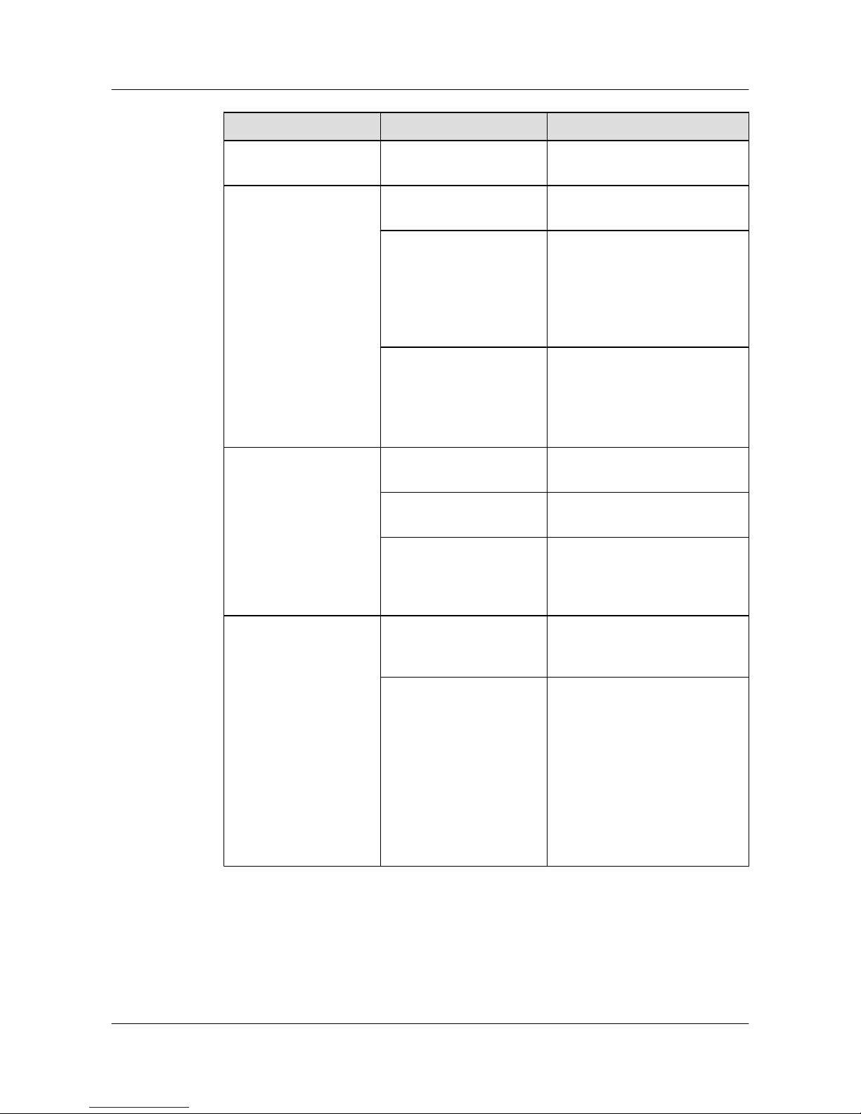
Display Mode Status Description
Blinking green The interface is sending or
receiving data.
Speed Off The interface is not connected or
has been shut down.
Green 10M/100M/1000M interface: The
interface is operating at 10/100
Mbit/s.
1000M/10G interface: The
interface is operating at 1000
Mbit/s.
Blinking green
10M/100M/1000M interface: The
interface is operating at 1000
Mbit/s.
1000M/10G interface: The
interface is operating at 10 Gbit/s.
PoE Off The interface does not provide
remote power.
Green The interface is providing remote
power.
Blinking green
l The power of the powered
device (PD) exceeds the power
supply capability of the port or
exceeds the threshold.
Stack Off The stack ID of the member
switch is not the number of the
interface in the off state.
Green The device is a not a command
switch:
l If the indicator of an interface
is steady on, the number of this
interface is the stack ID of the
device.
l If the first nine interface
indicators of the device are
steady on, the stack ID of the
device is 0.
S3700&S5700&S6700 Series Ethernet Switches
Quick Start 2 Product Hardware Introduction
Issue 02 (2012-09-10) Huawei Proprietary and Confidential
Copyright © Huawei Technologies Co., Ltd.
36
Page 42
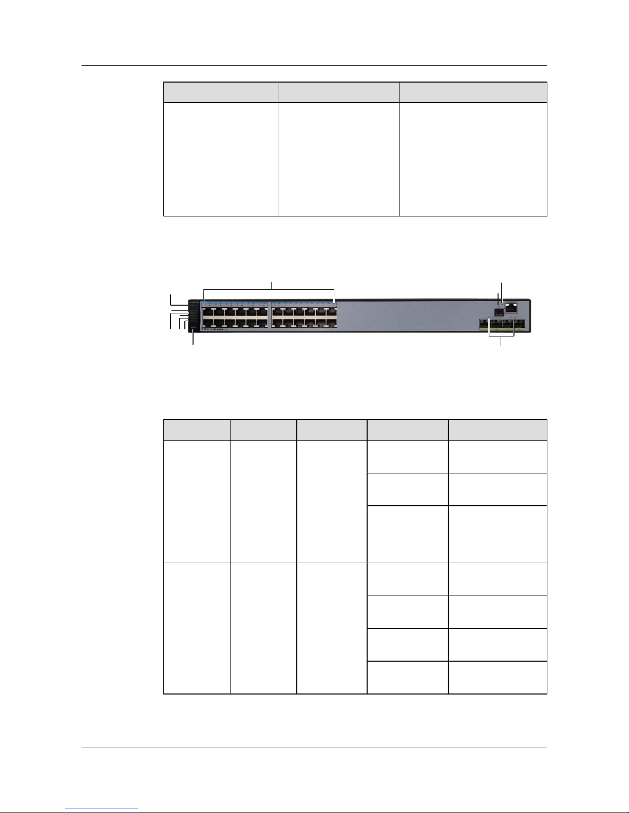
Display Mode Status Description
Blinking green The device is a command switch:
l If the indicator of an interface
blinks, the number of this
interface is the stack ID of the
device.
l If the first nine interface
indicators of the device blink,
the stack ID of the device is 0.
Figure 2-10 S5700-28P-PWR-LI-AC indicators
1
2
4
3
56
7
8
8
9
10
Table 2-17 Description of S5700-28P-PWR-LI-AC indicators
No.
Indicator Identifier Status Description
1 Power
indicator
PWR Off The switch is
powered off.
Green The switch is
powered on.
Orange The power supply
unit is faulty, and the
external RPS system
has started.
2 System status
indicator
SYS Off The system is not
operating.
Blinking green
quickly (4 Hz)
The system is starting.
Blinking green
slowly (0.5 Hz)
The system is
operating properly.
Blinking orange
(0.5 Hz)
The system is
sleeping.
S3700&S5700&S6700 Series Ethernet Switches
Quick Start 2 Product Hardware Introduction
Issue 02 (2012-09-10) Huawei Proprietary and Confidential
Copyright © Huawei Technologies Co., Ltd.
37
Page 43
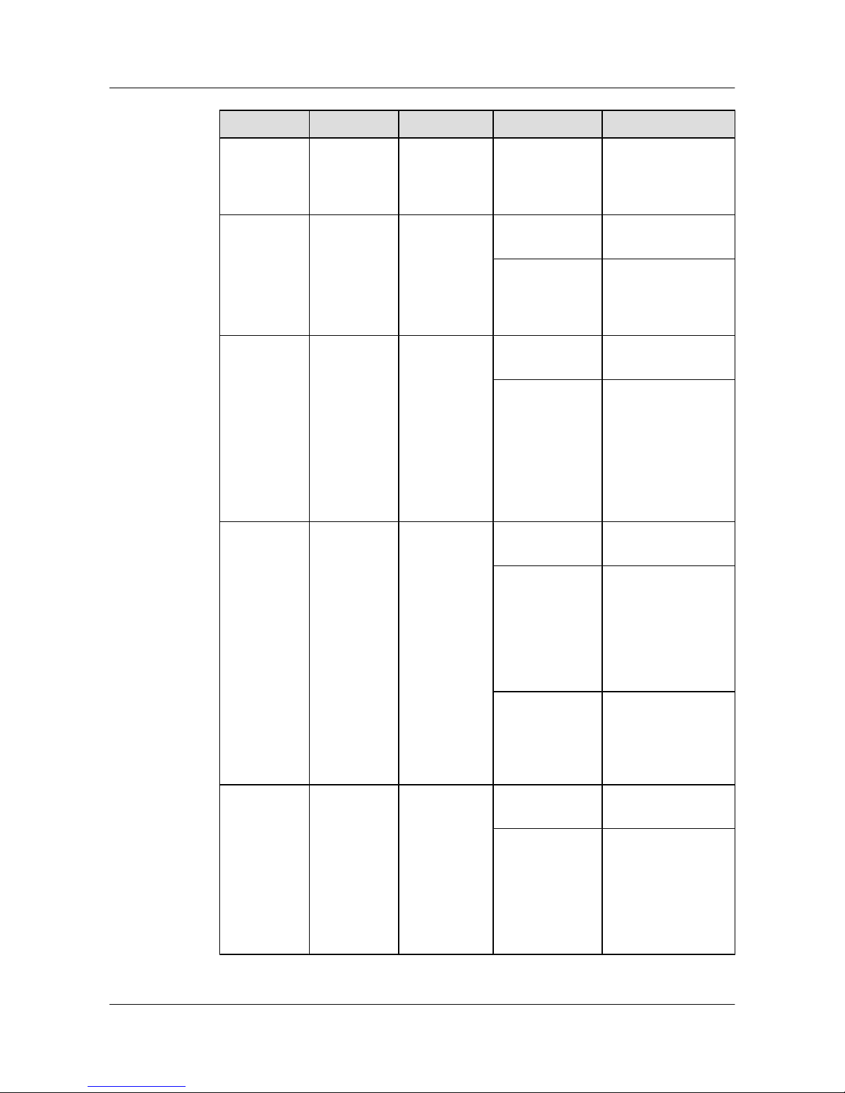
No. Indicator Identifier Status Description
Red The system does not
operate properly, or a
power alarm, fan
alarm is generated.
3 STAT
indicator
STAT Off The indicator is not in
the STAT mode.
Green The service interface
indicator is in the
default mode
(STAT).
4 Speed
indicator
SPED Off The indicator is not in
the speed mode.
Green The service interface
indicator indicates the
interface speed. After
45 seconds, the
service interface
indicator
automatically restores
to STAT.
5
Stack
indicator
STCK Off The indicator is not in
the stack mode.
Green The service interface
indicator indicates the
stack ID. After 45
seconds, the service
interface indicator
automatically restores
to STAT.
Blinking green
The indicator
indicates the active
device in a stack or a
device not added to a
stack.
6 PoE indicator PoE Off The indicator is not in
the PoE mode.
Green The service interface
indicator indicates the
PoE status. After 45
seconds, the service
interface indicator
automatically restores
to STAT.
S3700&S5700&S6700 Series Ethernet Switches
Quick Start 2 Product Hardware Introduction
Issue 02 (2012-09-10) Huawei Proprietary and Confidential
Copyright © Huawei Technologies Co., Ltd.
38
Page 44
No. Indicator Identifier Status Description
7 Mode
switching
button
MODE -
l When you press
the button once,
the SPED
indicator turns
green and the
service interface
indicators show
the speed status of
interfaces.
l When you press
the button for a
second time, the
STCK indicator
turns green and the
service interface
indicators show
the stack status of
interfaces.
l When you press
the button for a
third time, the PoE
indicator turns
green and the
service interface
indicators show
the PoE status.
l When you press
the button for a
fourth time, the
STAT indicator
turns green.
If you do not press the
button within 45
seconds, the
indicators restore to
the default status.
That is, the STAT
indicator turns green,
and the SPED, STCK
and PoE indicators
are off.
S3700&S5700&S6700 Series Ethernet Switches
Quick Start 2 Product Hardware Introduction
Issue 02 (2012-09-10) Huawei Proprietary and Confidential
Copyright © Huawei Technologies Co., Ltd.
39
Page 45
No. Indicator Identifier Status Description
7 Service
interface
indicator
l GE
electrical
interfaces:
The first
indicator
shows the
status of
the bottom
left
interface.
The
indicators
correspond
to the
interfaces
from
bottom to
top and
from left to
right.
l GE optical
interfaces:
Each
optical
interface
has a
correspond
ing
indicator
above it.
Off
Green
Blinking green
The meanings of
service interface
indicators vary
according to the
indicator status. For
details, see Table
2-18.
8
Mini USB
indicator
The indicators
for the Mini
USB port and
CON port are
close to each
other. The
Mini USB
indicator has
an arrowhead
pointing to the
Mini USB
port.
Off
The Mini USB port is
not in use.
Green The Mini USB port is
in use.
9 CON
indicator
The indicators
for the Mini
USB port and
CON port are
close to each
other. The
CON indicator
Off
The Mini USB port is
in use.
S3700&S5700&S6700 Series Ethernet Switches
Quick Start 2 Product Hardware Introduction
Issue 02 (2012-09-10) Huawei Proprietary and Confidential
Copyright © Huawei Technologies Co., Ltd.
40
Page 46
No. Indicator Identifier Status Description
has an
arrowhead
pointing to the
CON port.
Green The Mini USB port is
not in use. This
indicator is steady
green unless the Mini
USB port is accessed.
Table 2-18 Description of service interface indicators in different modes
Display Mode Status Description
STAT Off The interface is not connected or
has been shut down.
Green The interface is connected.
Blinking green The interface is sending or
receiving data.
Speed Off The interface is not connected or
has been shut down.
Green 10M/100M/1000M interface: The
interface is operating at 10/100
Mbit/s.
1000M/10G interface: The
interface is operating at 1000
Mbit/s.
Blinking green
10M/100M/1000M interface: The
interface is operating at 1000
Mbit/s.
1000M/10G interface: The
interface is operating at 10 Gbit/s.
PoE Off The interface does not provide
PoE power.
Green The interface is providing PoE
power.
Orange The PoE function on the interface
is disabled.
Blinking orange A PoE fault occurs. For example,
an incompatible cable or PD is
connected to the interface or the
PoE power supply unit is faulty.
S3700&S5700&S6700 Series Ethernet Switches
Quick Start 2 Product Hardware Introduction
Issue 02 (2012-09-10) Huawei Proprietary and Confidential
Copyright © Huawei Technologies Co., Ltd.
41
Page 47
Display Mode Status Description
Blinking green and orange
alternately
The interface cannot provide
power to PDs. The possible
reasons including:
l The power of a connected PD
exceeds the interface's
powering capability or upper
power supply threshold.
l The power provided by the
switch has reached the
powering capability of the
switch.
l The PoE power function is not
enabled on the interface in
manual power-management
mode.
Stack
Off The stack ID of the member
switch is not the number of the
interface in the off state.
Green The device is a not a command
switch:
l If the indicator of an interface
is steady on, the number of this
interface is the stack ID of the
device.
l If the first nine interface
indicators of the device are
steady on, the stack ID of the
device is 0.
Blinking green
The device is a command switch:
l If the indicator of an interface
blinks, the number of this
interface is the stack ID of the
device.
l If the first nine interface
indicators of the device blink,
the stack ID of the device is 0.
2.6 S6700 Indicator Description
This section describes the indicators on the S6700 front panel.
Indicators of S6700 Switch
In the following description, the indicators of S6700-24-EI are described as an example.
S3700&S5700&S6700 Series Ethernet Switches
Quick Start 2 Product Hardware Introduction
Issue 02 (2012-09-10) Huawei Proprietary and Confidential
Copyright © Huawei Technologies Co., Ltd.
42
Page 48
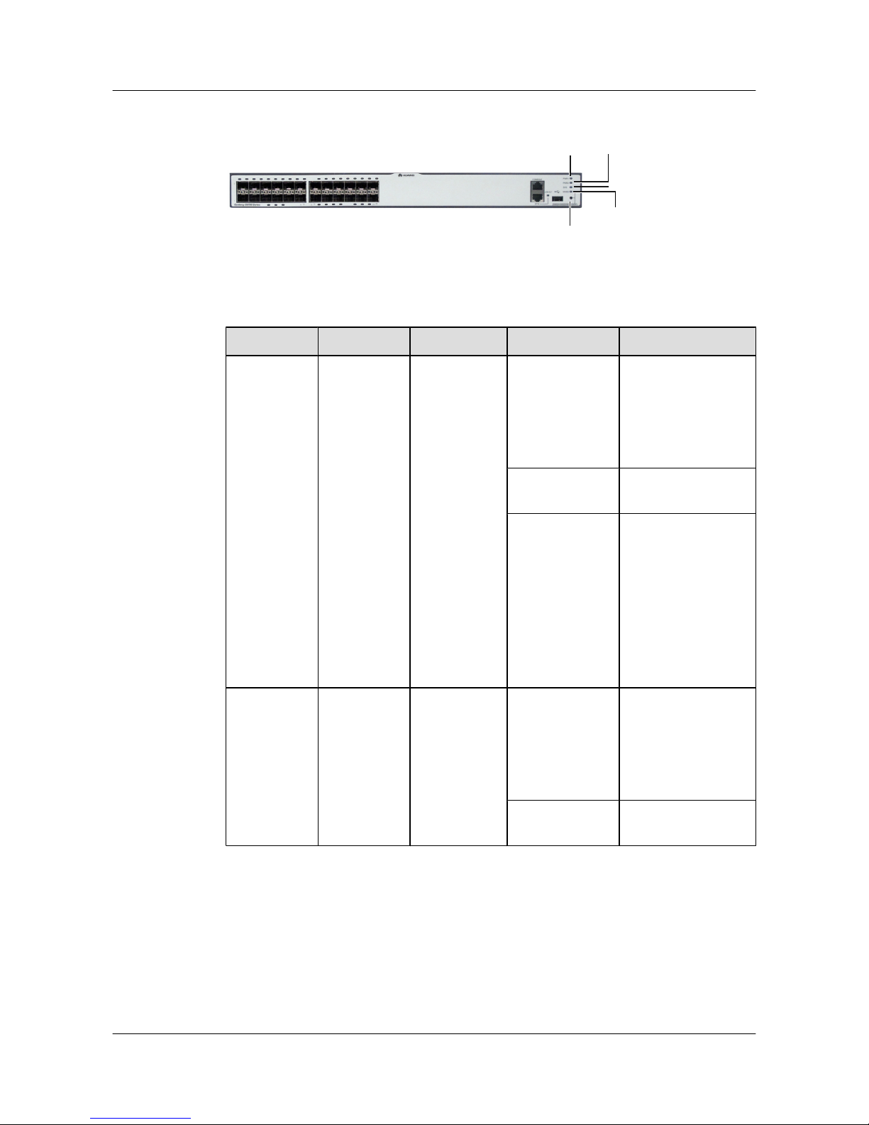
Figure 2-11 S6700-24-EI indicators
2
3
4
5
1
Table 2-19 Description of S6700-24-EI indicators
No. Indicator Identifier Status Description
1 Power
indicator
PWR1 Off The power supply
units are not present,
or the power supply is
abnormal when a
single power supply
unit is used.
Green The power supply is
normal.
Red
l Two power supply
units are installed
properly, but not
switched on.
l The power supply
units are switched
off.
l The power supply
units are faulty.
2
Power
indicator
PWR2 Off The power supply
units are not present,
or the power supply is
abnormal when a
single power supply
unit is used.
Green The power supply is
normal.
S3700&S5700&S6700 Series Ethernet Switches
Quick Start 2 Product Hardware Introduction
Issue 02 (2012-09-10) Huawei Proprietary and Confidential
Copyright © Huawei Technologies Co., Ltd.
43
Page 49
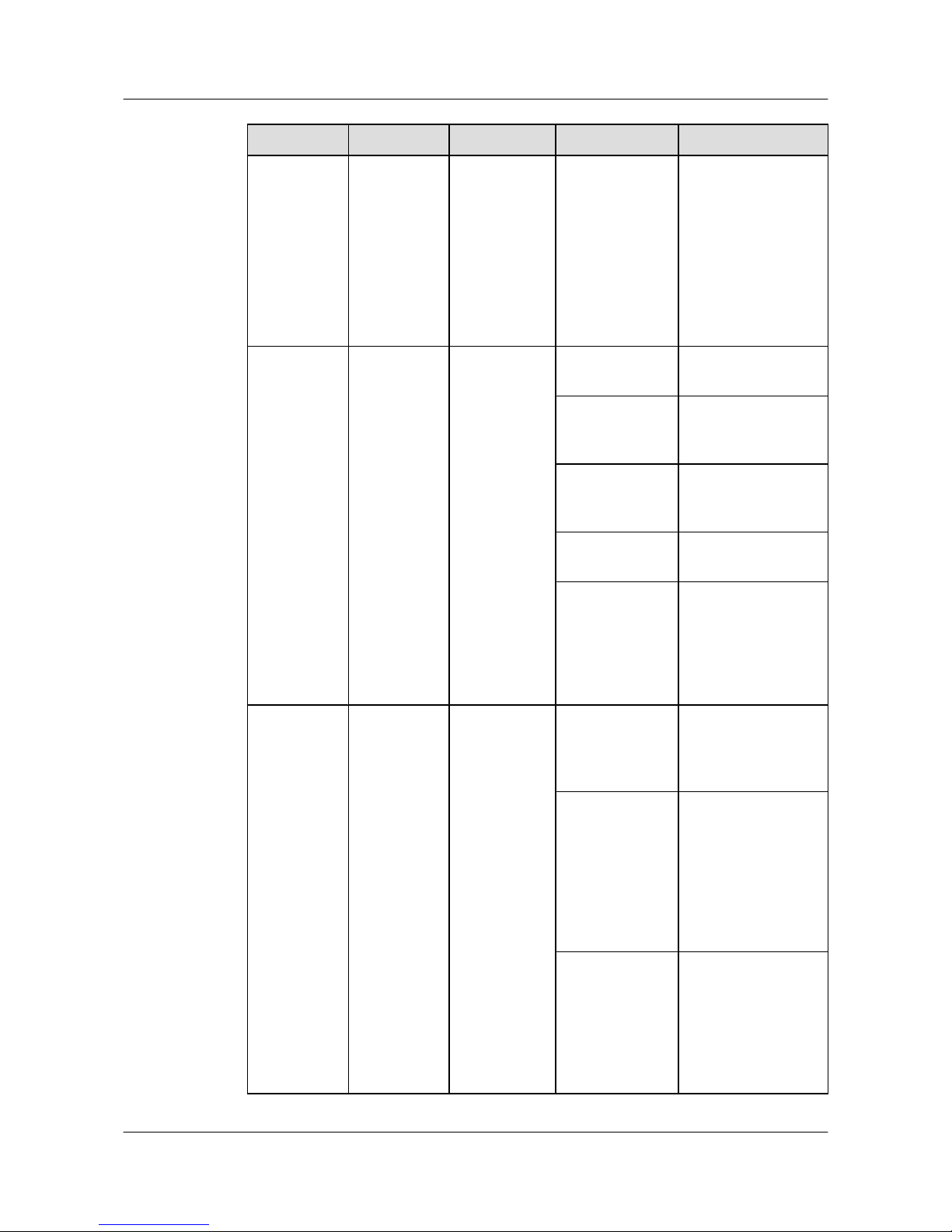
No. Indicator Identifier Status Description
Red
l Two power supply
units are installed
properly, but not
switched on.
l The power supply
units are switched
off.
l The power supply
units are faulty.
3
System status
indicator
SYS Off The system is not
operating.
Green The system is not
operating properly or
is starting.
Orange The system is
performing selfcheck during startup.
Blinking green The system is
operating properly.
Red After registering, the
system does not
operate properly, or a
power alarm, fan
alarm, or temperature
alarm is generated.
4 Mode
indicator
MODE Off The service interface
indicator is in the
default mode
(STAT).
Green The service interface
indicator indicates the
interface speed. After
45 seconds, the
service interface
indicator
automatically restores
to off.
Red
The service interface
indicator indicates the
stack ID. After 45
seconds, the service
interface indicator
automatically restores
to off.
S3700&S5700&S6700 Series Ethernet Switches
Quick Start 2 Product Hardware Introduction
Issue 02 (2012-09-10) Huawei Proprietary and Confidential
Copyright © Huawei Technologies Co., Ltd.
44
Page 50
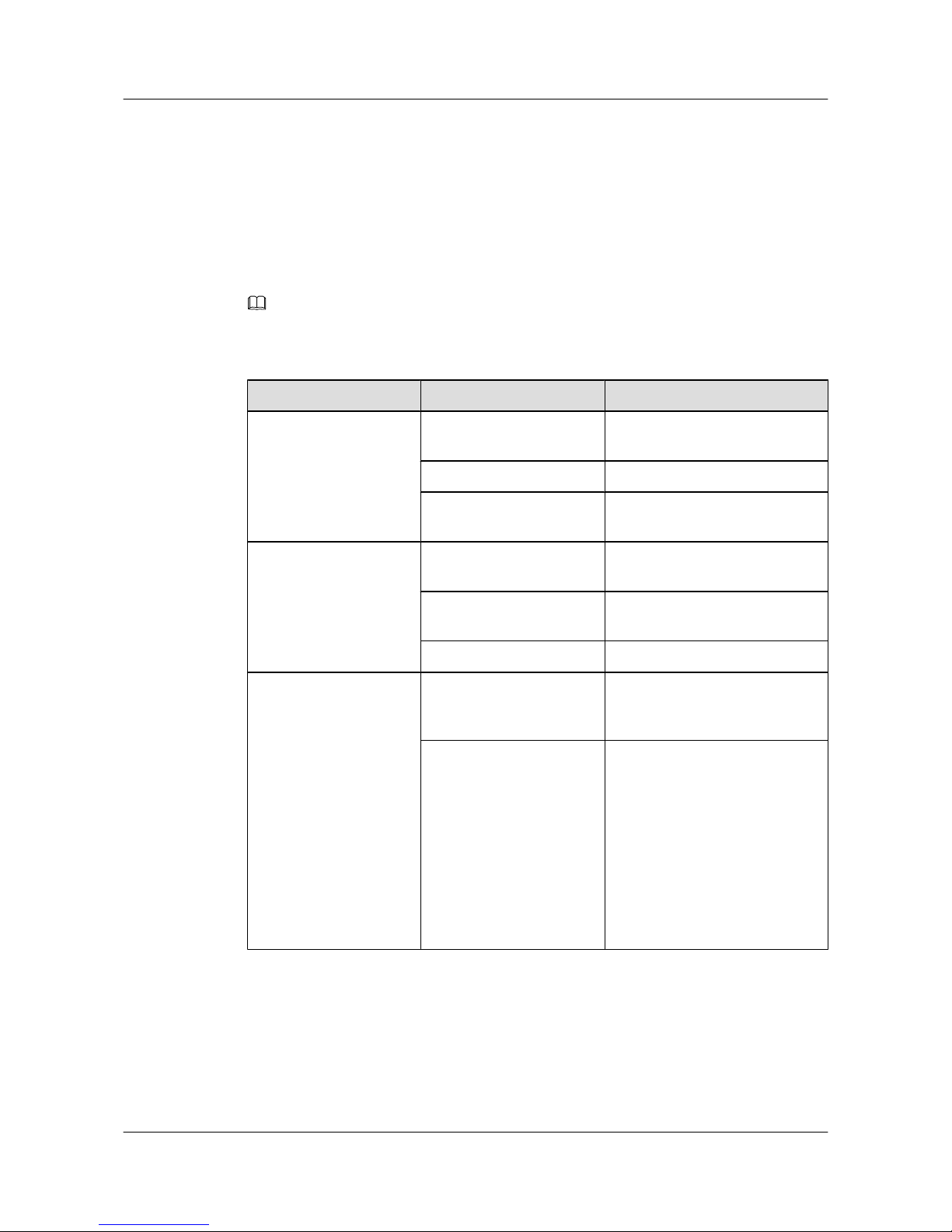
As shown in Figure 2-11, the button marked "5" is the mode switching button. When you press
the mode switching button once, the mode indicator turns green and the related interface indicator
enters the speed state. When you press the mode switching button for a second time, the mode
indicator turns red and the related interface indicator represents the stack status. If you do not
press the mode switching button within 45 seconds, the mode indicator automatically restores
to off. The following table describes the meanings of indicators.
NOTE
PWR1 is at the side of the chassis.
Table 2-20 Description of indicators in different modes
Display Mode Status Description
STAT Off The interface is not connected or
has been shut down.
Green The interface is connected.
Blinking green The interface is sending or
receiving data.
Speed Off The interface is not connected or
has been shut down.
Green The interface speed is 1000 Mbit/
s.
Blinking green The interface speed is 10 Gbit/s.
Stack Off The stack ID of the member
switch is not the number of the
interface in the off state.
Green The device is a not a command
switch:
l If the indicator of an interface
is always on, the number of this
interface is the stack ID of the
device.
l If the first nine interface
indicators of the device are
always on, the stack ID of the
device is 0.
S3700&S5700&S6700 Series Ethernet Switches
Quick Start 2 Product Hardware Introduction
Issue 02 (2012-09-10) Huawei Proprietary and Confidential
Copyright © Huawei Technologies Co., Ltd.
45
Page 51
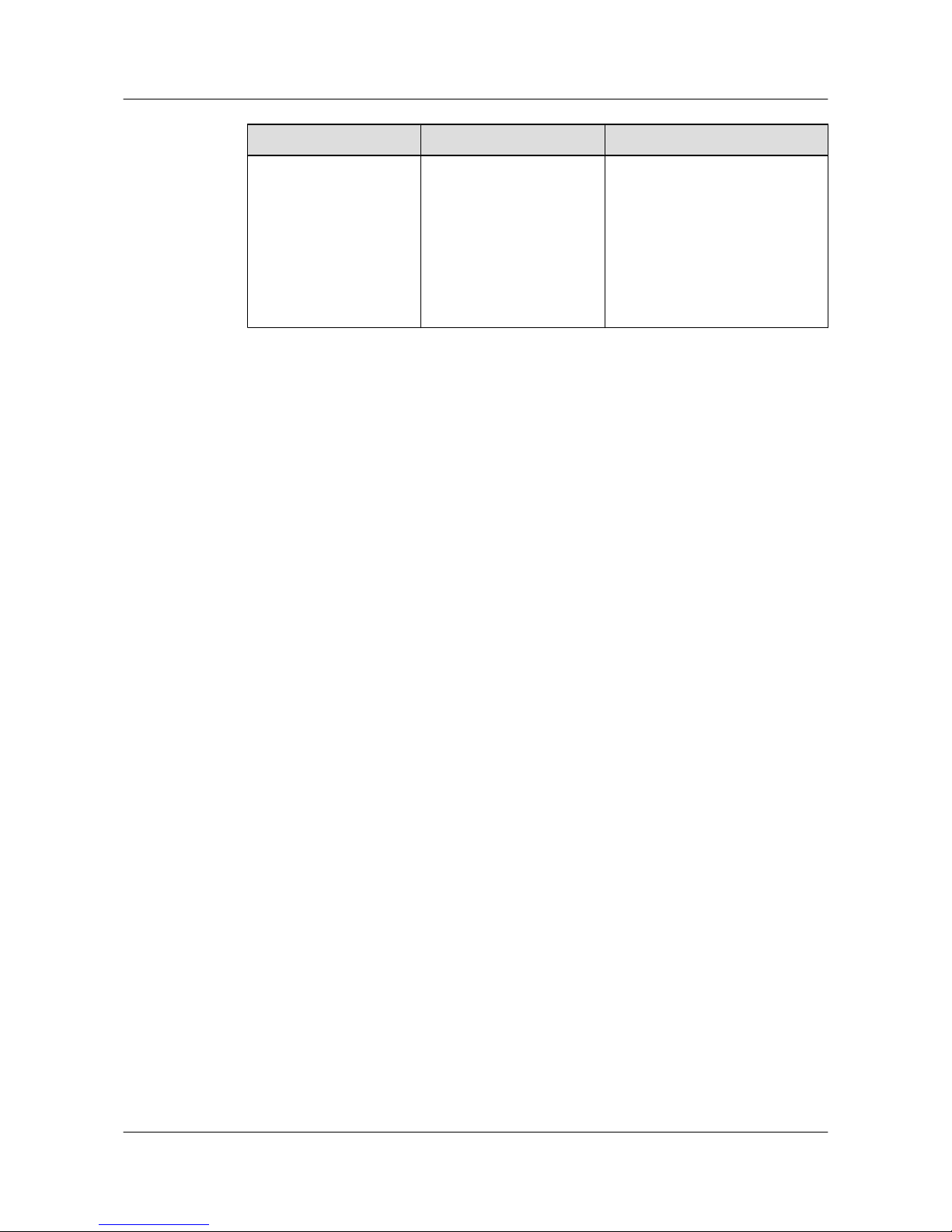
Display Mode Status Description
Blinking green The device is a command switch:
l If the indicator of an interface
blinks, the number of this
interface is the stack ID of the
device.
l If the first nine interface
indicators of the device blink,
the stack ID of the device is 0.
S3700&S5700&S6700 Series Ethernet Switches
Quick Start 2 Product Hardware Introduction
Issue 02 (2012-09-10) Huawei Proprietary and Confidential
Copyright © Huawei Technologies Co., Ltd.
46
Page 52

3 Device Installation
This section describes how to install the S3700/S5700/S6700.
For details on device installation, see the S2700&3700&5700&6700 Quick Installation Guide.
NOTE
You can obtain the paper documentation of the quick start from delivered accessories. To obtain the electronic
documentation of the quick start, see Where to Obtain Documentation.
S3700&S5700&S6700 Series Ethernet Switches
Quick Start 3 Device Installation
Issue 02 (2012-09-10) Huawei Proprietary and Confidential
Copyright © Huawei Technologies Co., Ltd.
47
Page 53

4 Powering on the Device
About This Chapter
This section describes the check items and the procedure for powering on and powering off the
device.
4.1 Checking Before Power-on
After hardware installation is complete, you need to check the device installation and cable
installation.
4.2 Powering on the Device
4.3 Checking After Power-on
S3700&S5700&S6700 Series Ethernet Switches
Quick Start 4 Powering on the Device
Issue 02 (2012-09-10) Huawei Proprietary and Confidential
Copyright © Huawei Technologies Co., Ltd.
48
Page 54
4.1 Checking Before Power-on
After hardware installation is complete, you need to check the device installation and cable
installation.
NOTE
Before power-on, you need to check the device cabinet, cables, connectors, sockets, labels, and on-site
environment.
Device Installation Checklist
CAUTION
Before power-on, all the power distribution cabinets and power distribution frames must be off.
Table 4-1 describes the device installation checklist.
Table 4-1 Device installation checklist
No.
Item Method
1 The cabinet is installed according to the
dimensions on the design paper.
Check the cabinet according to the
project design document.
2 The expansion bolts for fixing the
cabinet or base (support) to the ground
are fastened. The plain washer, spring
washer, and nut (bolt) are installed
correctly.
-
S3700&S5700&S6700 Series Ethernet Switches
Quick Start 4 Powering on the Device
Issue 02 (2012-09-10) Huawei Proprietary and Confidential
Copyright © Huawei Technologies Co., Ltd.
49
Page 55
No. Item Method
3 The installation holes on the support and
the expansion bolts adapt to each other
to ensure insulation between the support
and the ground and between the floor
bracket and the guide rail.
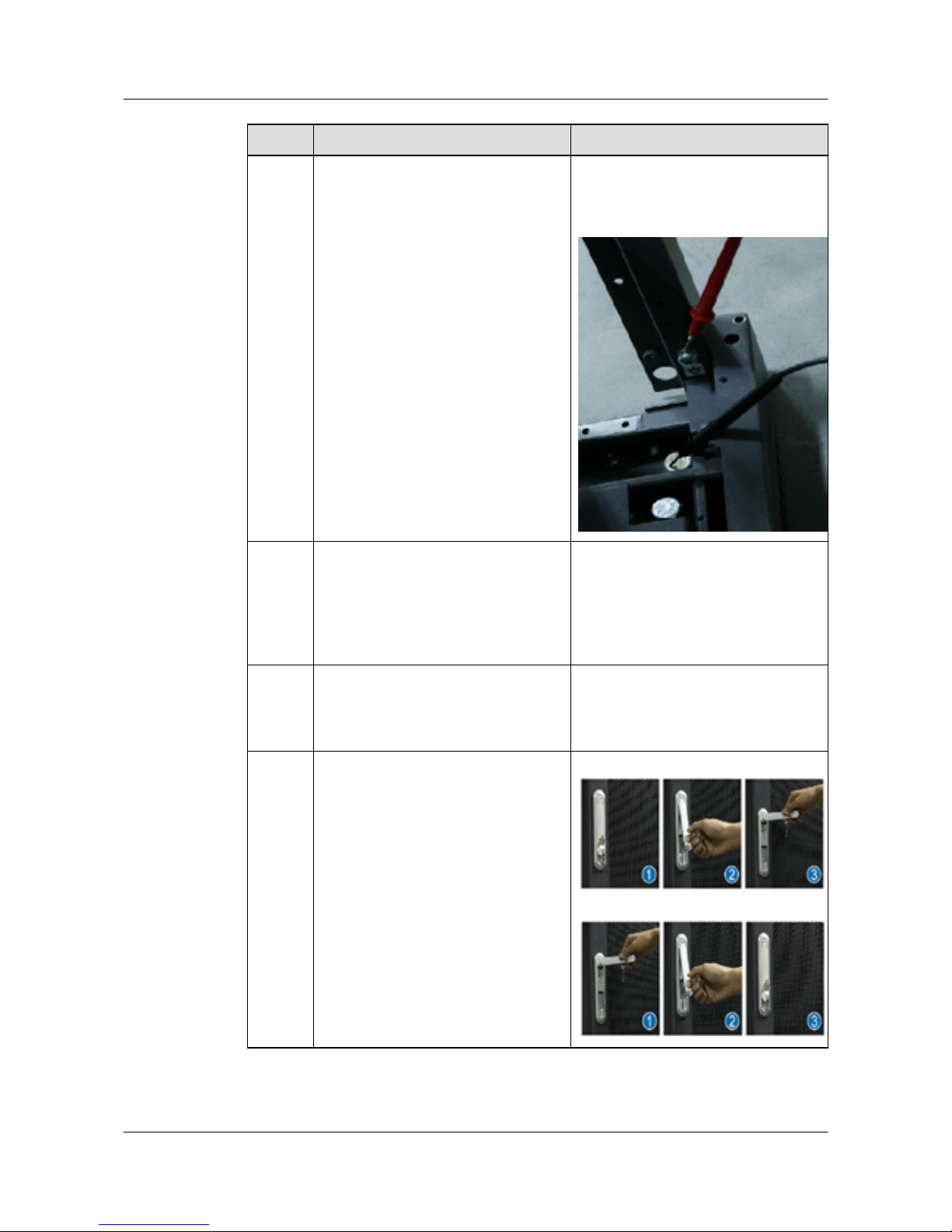
Use the multimeter to measure the
resistance between the bolt and the
ground bolt of the rack. The resistance
must be more than five mega ohms.
4 The surfaces of the cabinets in the same
row should be on the same plane. The
cabinets are arranged closely and tidily.
The cabinets on the sides of the main
path are aligned. The position error
should be less than 5 mm.
-
5 The accessories of the front and rear
doors are completely installed and the
connection board is installed for
combining cabinets.
-
6 The front door of a cabinet can be
opened and closed easily.
Open the door lock.
Close the door lock.
S3700&S5700&S6700 Series Ethernet Switches
Quick Start 4 Powering on the Device
Issue 02 (2012-09-10) Huawei Proprietary and Confidential
Copyright © Huawei Technologies Co., Ltd.
50
Page 56
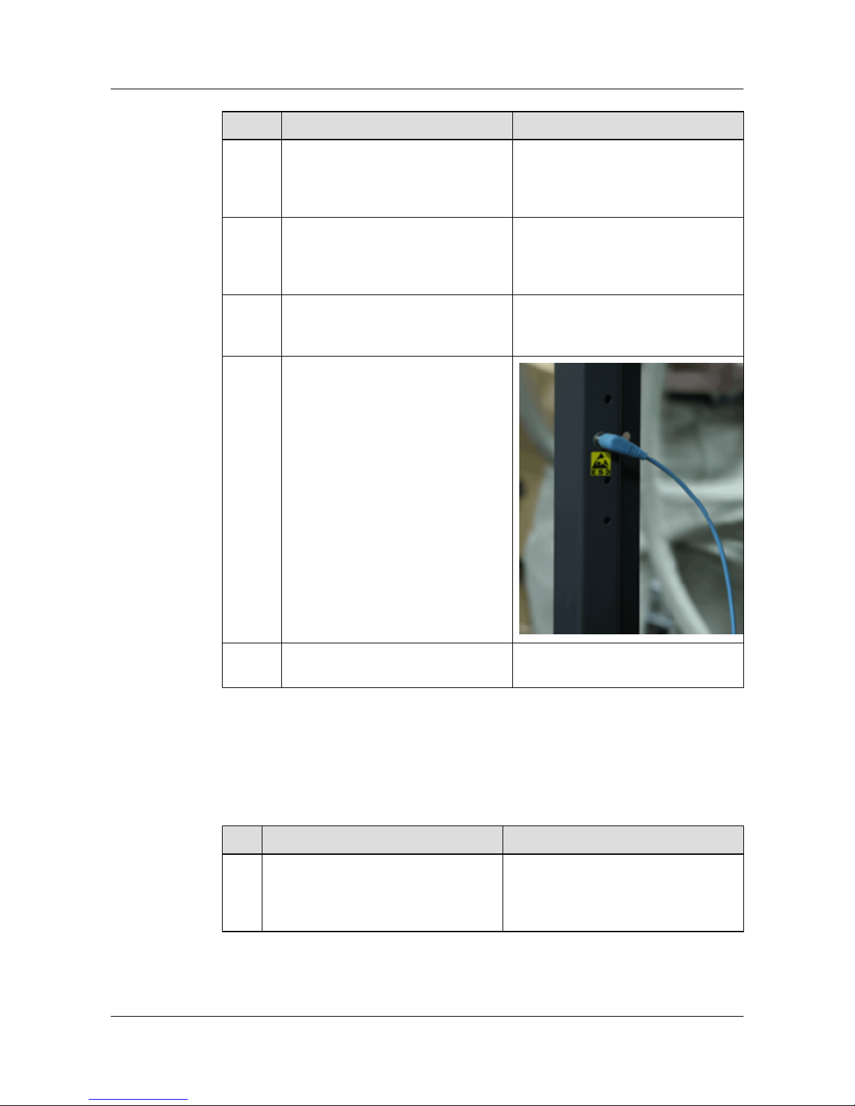
No. Item Method
7 The card is installed and removed
easily. The screws on the panel should
be appropriately tightened and easily
disassembled. The spring wire is intact.
-
8 The cabinet surface must be tidy and
clean; the components of the cabinet
cannot be distorted; all identifiers are
correct, clear, and complete.
-
9 The cabinet is kept clean and there are
no excessive binding straps and other
articles in the cabinet.
-
10 The ESD wrist straps are connected the
ESD jack in the chassis.
11 Blank panels are installed in all empty
slots.
-
Cable Installation Checklist
Table 4-2 describes the cable installation checklist.
Table 4-2 Cable installation checklist
No.
Item Method
1 The power cables and ground cables must
be the copper wires and have no splice.
The cables are safely connected
complying with standards.
-
S3700&S5700&S6700 Series Ethernet Switches
Quick Start 4 Powering on the Device
Issue 02 (2012-09-10) Huawei Proprietary and Confidential
Copyright © Huawei Technologies Co., Ltd.
51
Page 57
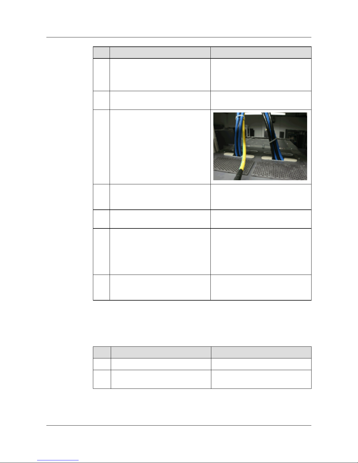
No. Item Method
2 The power cables and ground cables are
connected safely. The spring washer of
the ground cable terminal is on the flat
washer.
-
3 The lugs of the power cables and ground
cables are soldered or crimped tightly.
-
4 The power cables and ground cables are
not crossed and are separated from other
cables.
5 The redundant part of the power cables
and ground cables should be cut. The
cables cannot be circled.
-
6 The ground cables must be tightly
connected to the doors of the cabinet.
-
7 Labels are filled and attached to power
cables and PGND cables; power cables
and PGND cables including power
distribution switches are labeled correctly
and clearly. Labels are attached 20 mm
from the connector.
-
8 The clearance between the power cable,
PGND cable, and signal cable must be
more than 30 mm.
-
Table 4-3 describes the cabinet cable checklist.
Table 4-3 Cabinet cable checklist
No.
Item Method
1 Cables are correctly connected. -
2 Cable ties are not overlapped and
connectors are smooth.
-
Table 4-4 describes the signal cable checklist.
S3700&S5700&S6700 Series Ethernet Switches
Quick Start 4 Powering on the Device
Issue 02 (2012-09-10) Huawei Proprietary and Confidential
Copyright © Huawei Technologies Co., Ltd.
52
Page 58
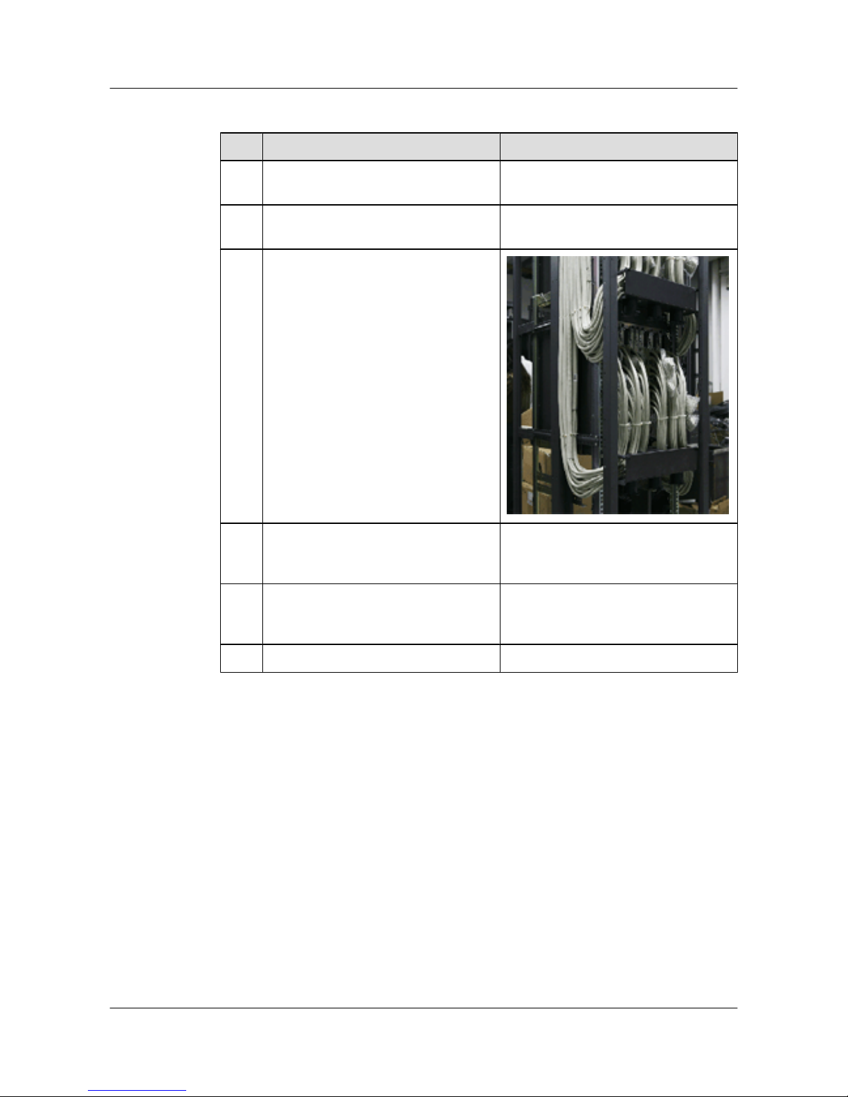
Table 4-4 Signal cable checklist
No. Item Method
1 All the signal cables to be deployed pass
the continuity check.
-
2 No signal cable is placed on the heat
dissipation holes of the cabinet.
-
3 The bent part of a signal cable cannot be
too tight.
4 The cables in the cabinet cannot be
crossed and the cables outside the cabinet
are bound.
-
5 The two ends of a signal cable are clearly
identified by labels and the texts on the
labels are in the same direction.
-
6 The bolts that fix the cables are tightened. -
4.2 Powering on the Device
Turn on the power module of the device.
4.3 Checking After Power-on
Check the following items after the device is powered on:
l The sound of fan rotating can be heard and that the air exhaust from the air vents can be
felt.
l The indicators of the power modules run normally. Normally, the INPUT and OUTPUT
indicators are on.
l The indicators of the fan modules run normally. Normally, the STATUS indicator is on.
S3700&S5700&S6700 Series Ethernet Switches
Quick Start 4 Powering on the Device
Issue 02 (2012-09-10) Huawei Proprietary and Confidential
Copyright © Huawei Technologies Co., Ltd.
53
Page 59

5 Logging in to the Device
About This Chapter
This section describes how to log in to the device.
5.1 Logging In to the Switch Through the Console Interface
5.2 Example for Configuring to Manage the SwitchThrough Telnet
5.3 Logging In to the Web System Client
Before configuring the switch, you must log in to the Web system client.
S3700&S5700&S6700 Series Ethernet Switches
Quick Start 5 Logging in to the Device
Issue 02 (2012-09-10) Huawei Proprietary and Confidential
Copyright © Huawei Technologies Co., Ltd.
54
Page 60
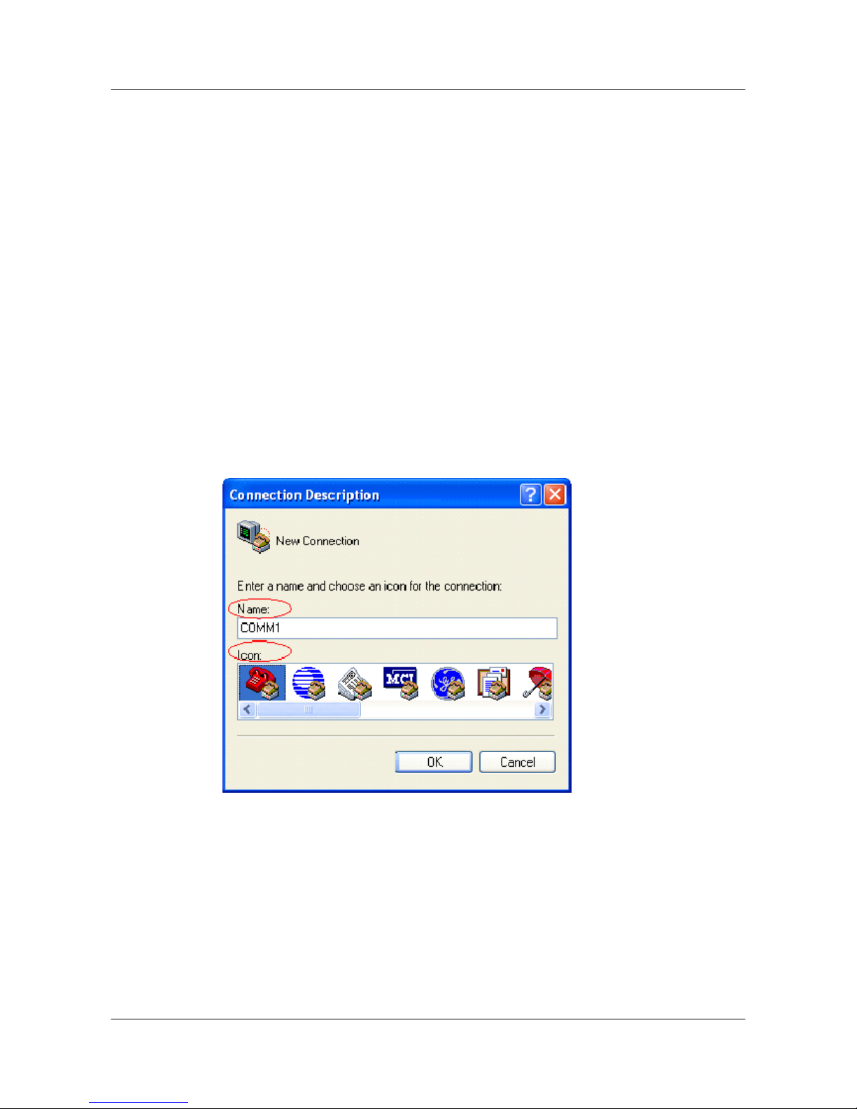
5.1 Logging In to the Switch Through the Console Interface
Context
When establishing the configuration environment through the console interface, you can log in
to the S3700/S5700/S6700 through the HyperTerminal in Windows.
Procedure
Step 1 Start the HyperTerminal.
Choose Start > All Program > Accessories > Communications > HyperTerminal to start the
HyperTerminal in Windows XP.
Step 2 Set up a connection.
See Figure 5-1. Enter the name of the new connection in the Name text box and then choose
one icon. Then, click OK.
Figure 5-1 Setting up a connection
Step 3 Configure an interface for connection.
In the Connect To dialog box, as shown in Figure 5-2, select an interface from the drop-down
list box according to the actual interface on the PC or terminal. Next, click OK.
S3700&S5700&S6700 Series Ethernet Switches
Quick Start 5 Logging in to the Device
Issue 02 (2012-09-10) Huawei Proprietary and Confidential
Copyright © Huawei Technologies Co., Ltd.
55
Page 61
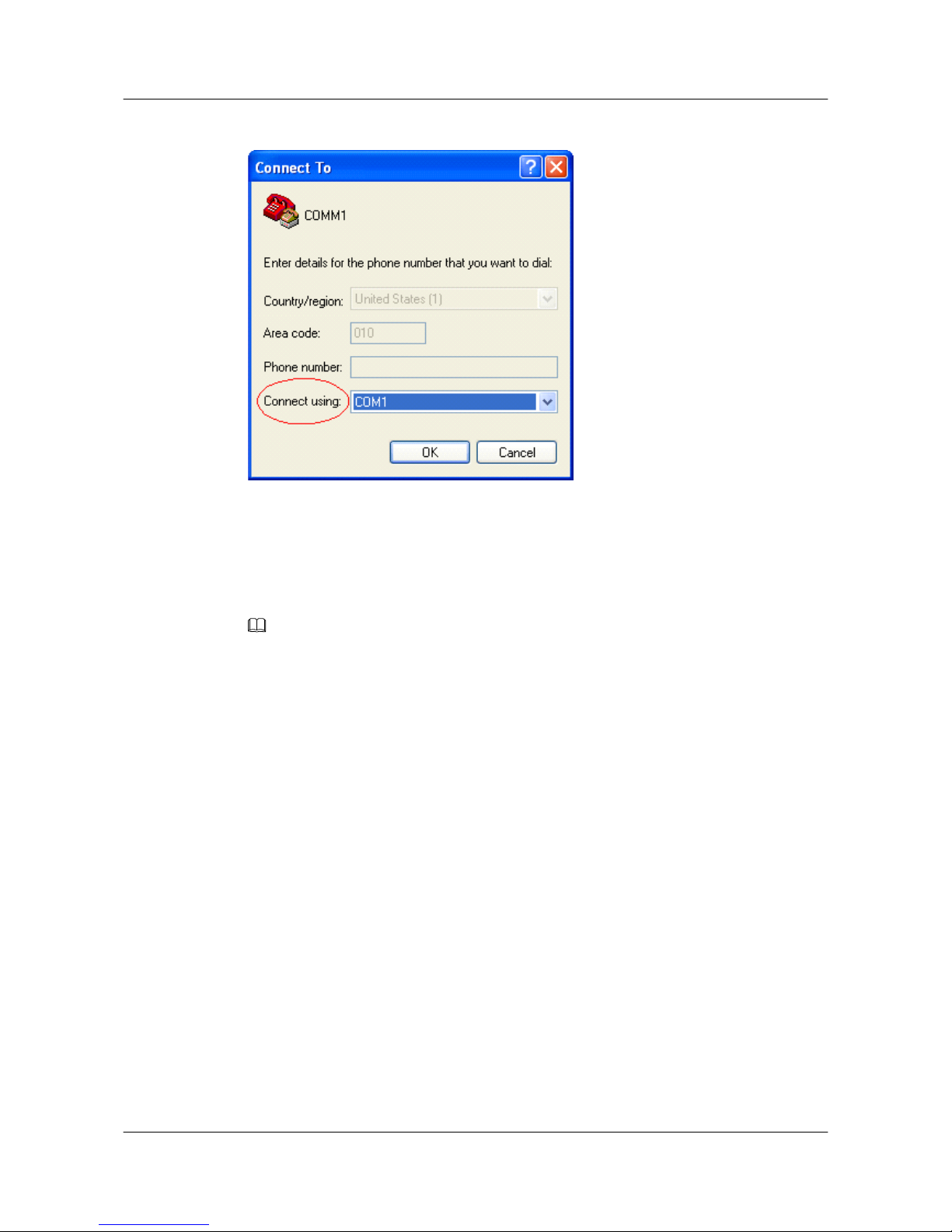
Figure 5-2 Configuring the interface for connection
Step 4 Set communication parameters.
When the COM1 Properties dialog box is displayed as shown in Figure 5-3, specify the
parameters listed in Table 5-1.
NOTE
In other Windows operating systems, bits per second may be described as baud rate and data stream control
may be described as traffic control.
S3700&S5700&S6700 Series Ethernet Switches
Quick Start 5 Logging in to the Device
Issue 02 (2012-09-10) Huawei Proprietary and Confidential
Copyright © Huawei Technologies Co., Ltd.
56
Page 62
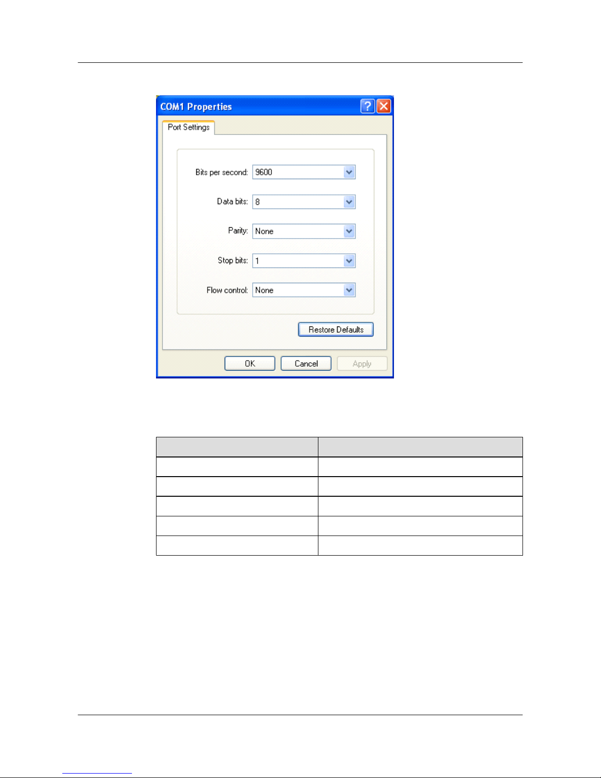
Figure 5-3 Specifying parameters
Table 5-1 Parameters
Parameter
Value
Bit per second (baud rate) 9600
Data bit 8
Parity check None
Stop bit 1
Flow control (traffic control) None
Step 5 After the HyperTerminal starts, choose FileAttributes to display the COMM1 Properties
dialog box, as shown in Figure 5-4. On the Setting tab, select VT100 in the Emulation dropdown list box. Click OK to complete the setting.
S3700&S5700&S6700 Series Ethernet Switches
Quick Start 5 Logging in to the Device
Issue 02 (2012-09-10) Huawei Proprietary and Confidential
Copyright © Huawei Technologies Co., Ltd.
57
Page 63
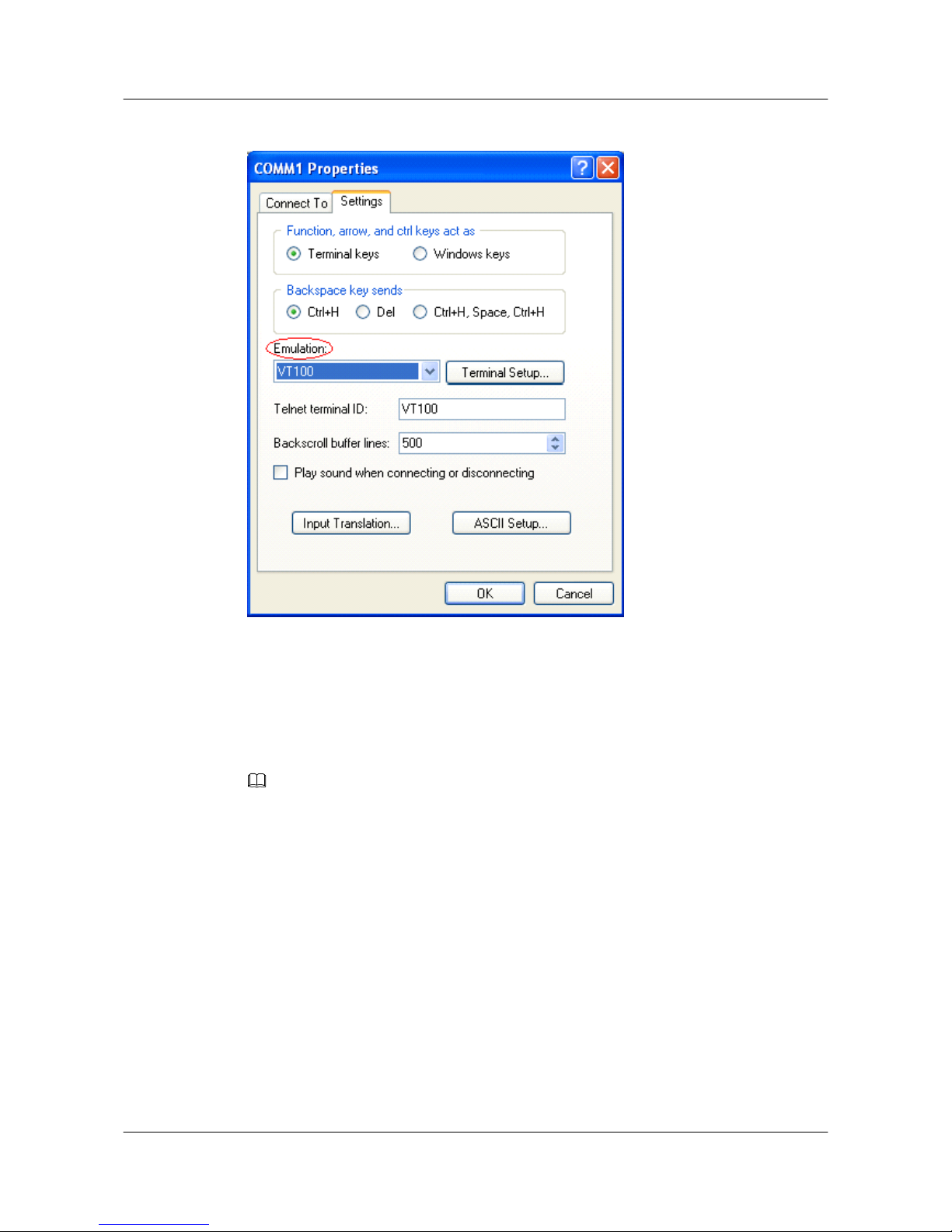
Figure 5-4 Selecting the terminal type
Step 6 Press Enter. At the following command-line prompt, set an authentication password. The system
automatically saves the set password.
Please configure the login password (maximum length 16)
Enter Password:
Confirm Password:
NOTE
After the password for the user interface is set successfully during the first login, you must enter this
password for authentication when you relog in to the system in password authentication mode using this
user interface.
----End
Follow-up Procedure
If the prompt <Quidway> is displayed on the screen, it indicates that the Command Line Interface
(CLI) is displayed. In this case, you can enter commands to configure or manage the S3700/
S5700/S6700. For details on configuration procedures, see the following sections.
5.2 Example for Configuring to Manage the SwitchThrough
Telnet
S3700&S5700&S6700 Series Ethernet Switches
Quick Start 5 Logging in to the Device
Issue 02 (2012-09-10) Huawei Proprietary and Confidential
Copyright © Huawei Technologies Co., Ltd.
58
Page 64
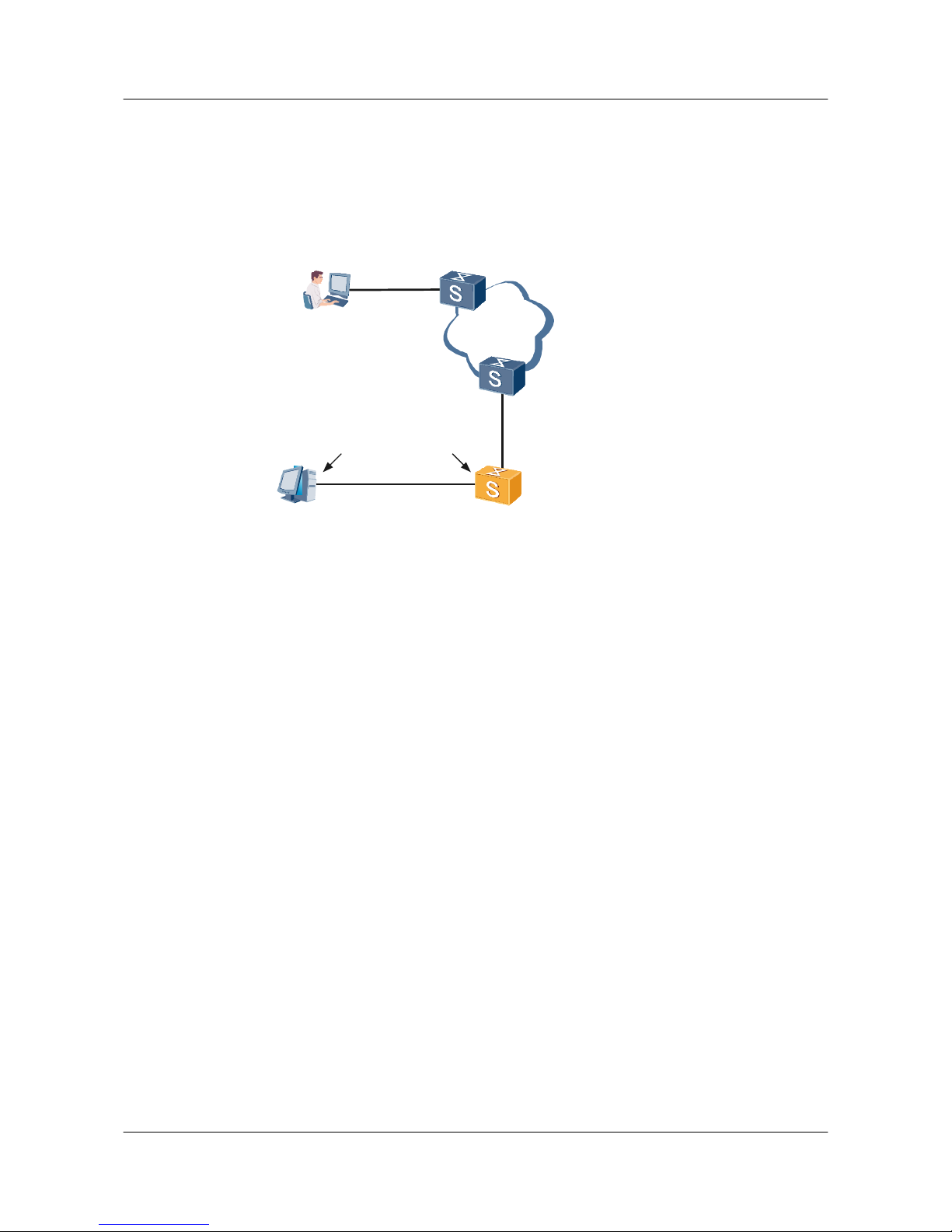
Networking Requirements
As shown in Figure 5-5, SwitchA is newly added to the network. SwitchA and SwitchB are
connected through a trunk link. To enable the network administrator to manage SwitchA
remotely, you need to configure the Telnet service and set the device name on SwitchA.
Figure 5-5 Networking diagram of managing SwitchA through Telnet
RS-232
Console cable
Console port
PC SwitchA
serial port
Ethernet
administrator
SwitchB
GE 0/0/1
GE 0/0/1
Configuration Roadmap
The configuration roadmap is as follows:
1. Log in to SwitchA through the console interface.
2. Set the device name.
3. Configure a management VLAN.
4. On SwitchA, set the type of the interface that connects SwitchA and SwitchB to trunk. Add
the interface to the management VLAN in trunk mode.
5. Configure the management IP address of SwitchA.
6. Configure the Telnet service.
Data Preparation
To complete the configuration, you need the following data:
l ID of the management VLAN
l Management IP address of SwitchA
l Number of the interface that connects SwitchA and SwitchB on SwitchA
l Authentication mode, user name, and password
Configuration Procedure
1. Log in to SwitchA through the console port. For details, see Logging In to the Switch
Through the Console Interface.
S3700&S5700&S6700 Series Ethernet Switches
Quick Start 5 Logging in to the Device
Issue 02 (2012-09-10) Huawei Proprietary and Confidential
Copyright © Huawei Technologies Co., Ltd.
59
Page 65

2. Set the device name of SwitchA.
<Quidway> system-view
[Quidway] sysname SwitchA
3. Configure a management VLAN.
[SwitchA] vlan 1
[SwitchA-vlan1] description admin_VLAN
4. On SwitchA, set the type of the interface that connects SwitchA and SwitchB to trunk. Add
the interface to the management VLAN in trunk mode.
[SwitchA] interface Gigabitethernet 0/0/1
[SwitchA-GigabitEthernet0/0/1] port link-type trunk
[SwitchA-GigabitEthernet0/0/1] port trunk allow-pass vlan 1
[SwitchA-GigabitEthernet0/0/1] quit
5. Configure the management IP address of SwitchA.
[SwitchA] interface vlanif 1
[SwitchA-Vlanif1] ip address 10.10.10.10 255.255.255.0
[SwitchA-Vlanif1] quit
6. Configure the Telnet service on SwitchA:
l Set the authentication method to AAA, user name to huawei, and password to huawei.
l Set the service type to telnet and user level to 15.
l Configure AAA authentication for the users at the vty 0 to vty 4 levels.
[SwitchA] aaa
[SwitchA-aaa] local-user huawei password simple huawei
[SwitchA-aaa] local-user huawei service-type telnet
[SwitchA-aaa] local-user huawei privilege level 15
[SwitchA-aaa] quit
[SwitchA] user-interface vty 0 4
[SwitchA-ui-vty0-4] authentication-mode aaa
[SwitchA-ui-vty0-4] return
<SwitchA>
7. Verify the configuration.
NOTE
When the administrator logs in to SwitchA through Telnet, ensure that the PC of the administrator
and SwitchA are reachable at the network layer.
<SwitchA> telnet 127.0.0.1
Trying 127.0.0.1 ...
Press CTRL+T to abort
Connected to 127.0.0.1 ...
***********************************************************
* All rights reserved (2005-2007) *
* Without the owner's prior written consent, *
* no decompiling or reverse-engineering shall be allowed. *
* Notice: *
* This is a private communication system. *
* Unauthorized access or use may lead to prosecution. *
***********************************************************
Login authentication
Username:huawei
Password:
Note: The max number of VTY users is 15, and the current number
of VTY users on line is 3.
<SwitchA>
S3700&S5700&S6700 Series Ethernet Switches
Quick Start 5 Logging in to the Device
Issue 02 (2012-09-10) Huawei Proprietary and Confidential
Copyright © Huawei Technologies Co., Ltd.
60
Page 66

Configuration Files
l SwitchA
#
sysname SwitchA
#
vlan batch 1
#
vlan 1
description admin_VLAN
#
interface Vlanif1
ip address 10.10.10.10 255.255.255.0
#
interface GigabitEthernet0/0/1
port link-type trunk
port trunk allow-pass vlan 1
#
aaa
local-user huawei password simple huawei
local-user huawei service-type telnet
local-user huawei privilege level 15
authentication-scheme default
#
authorization-scheme default
#
accounting-scheme default
#
domain default
#
user-interface con 0
user-interface vty 0 4
authentication-mode aaa
#
return
5.3 Logging In to the Web System Client
Before configuring the switch, you must log in to the Web system client.
Context
l Before logging in to the Web system client, ensure that the switch has been commissioned
and the Web system server is enabled on the switch.
l The Web system client connects to the switch through HTTP; therefore, you must log in
to the Web system client through HTTP.
l It is recommended that the Web system client should run the Windows XP operating system
because other operating systems may be imcompatible with the web system.And the Web
system client supports the Microsoft Internet Explorer 6.0 (IE6) and Firefox 3.0, or later
versions. The Web system client described in this document uses the IE6.
Procedure
Step 1 Open Microsoft Internet Explorer 6.0 on the client.
Step 2 Enter the universal resource locator (URL) of the Web system client in the address bar and press
Enter. The User Login dialog box is displayed, as shown in Figure 5-6.
The URL is in the format http://IP/view/login.html, for example, http://10.164.19.131/view/
login.html.
S3700&S5700&S6700 Series Ethernet Switches
Quick Start 5 Logging in to the Device
Issue 02 (2012-09-10) Huawei Proprietary and Confidential
Copyright © Huawei Technologies Co., Ltd.
61
Page 67
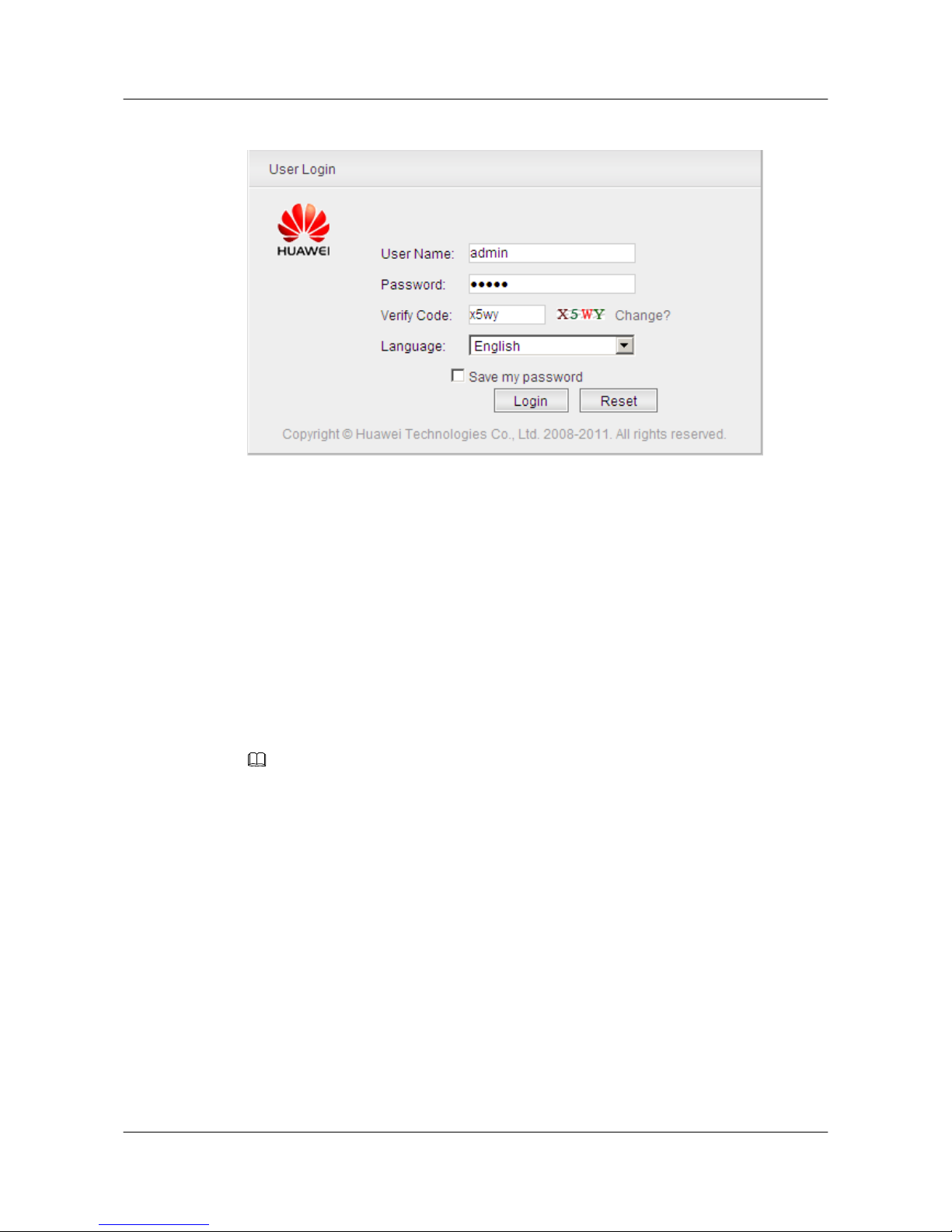
Figure 5-6 User Login
Step 3 Enter values in User Name, Password, and Verify Code.
l The local switch provides a default account. The user name and password of the account are
admin.
l To create, change, or delete user names and passwords, choose Security > AAA > User
Management.
l Users at levels 0, 1 and 2 have only visit-level rights, and can view only the Ping and
Tracert pages after logging in to the client.
Step 4 Choose a language, for example, English.
l The Web system client of the current version supports Chinese and English.
l After logging in to the client, you can select another language from the Language drop-down
list on the top right corner of the page.
Step 5 Click Login.
NOTE
If you select Save my password before clicking Login, you do not need to enter the user name and password
at next login.
After you log in to the Web system, the main page is displayed. For details about the main page,
see Window Layout.
----End
S3700&S5700&S6700 Series Ethernet Switches
Quick Start 5 Logging in to the Device
Issue 02 (2012-09-10) Huawei Proprietary and Confidential
Copyright © Huawei Technologies Co., Ltd.
62
Page 68

6 Service Deployment
This section describes service deployment.
For details on service deployment, see the corresponding configuration guides.
S3700&S5700&S6700 Series Ethernet Switches
Quick Start 6 Service Deployment
Issue 02 (2012-09-10) Huawei Proprietary and Confidential
Copyright © Huawei Technologies Co., Ltd.
63
Page 69
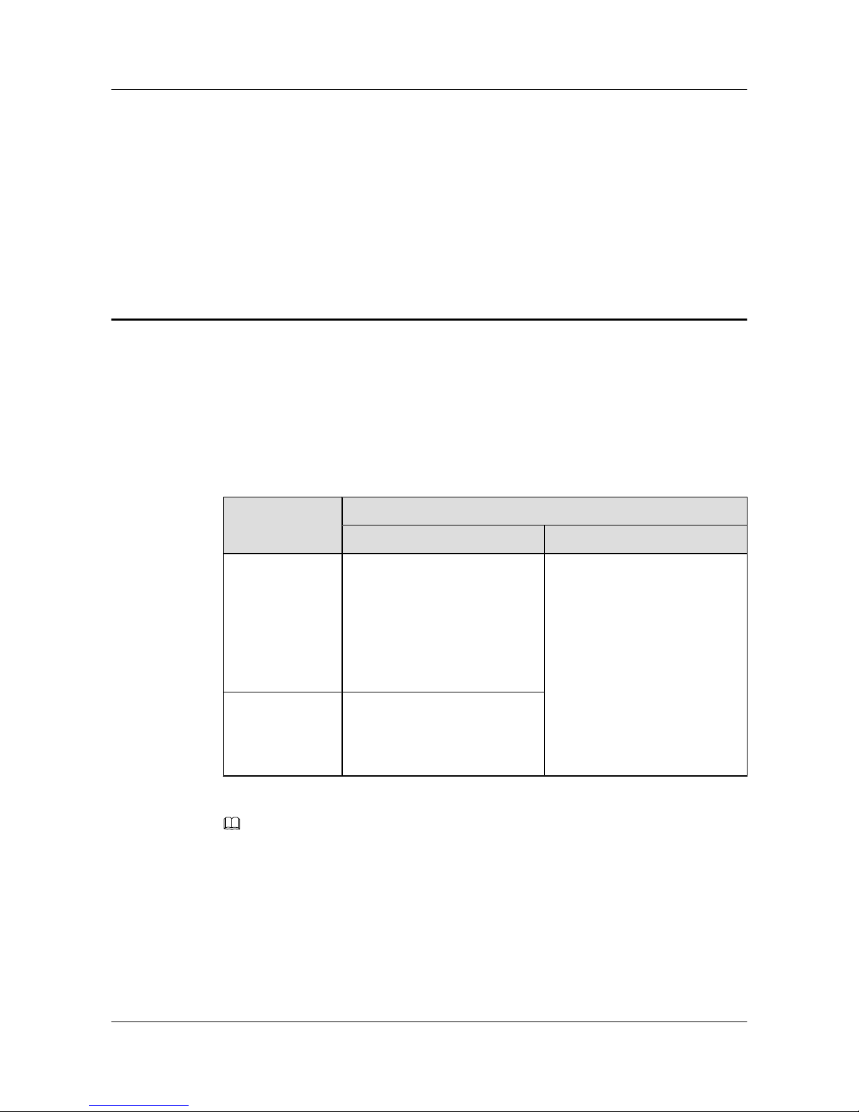
7 Obtaining Documentation
You can obtain product documentation, online help, and release documents in various ways.
Product Documents
Table 7-1 shows how to obtain product documents.
Table 7-1 Obtaining product documents
Phase
How to Obtain Documentation
HedEx Library Single Electronic Document
Installation
l From the electronic
documentation delivered with
the equipment
l From http://
support.huawei.com
l From the local Huawei
representative office
l From http://
support.huawei.com
l From http://
enterprise.huawei.com
Version upgrade
l From http://
support.huawei.com
l From the local Huawei
representative office
NOTE
l Obtain the product documents from http://support.huawei.com by choosing Documentation > Data
Communication. It is recommended that you use your work email to register as an equipment customer
for login to Huawei support website. For any help, contact Huawei technical support engineers.
l Obtain the product documents from http://enterprise.huawei.com by choosing Support >
Documentation Center > IP Network & Security > Switches.
Online Help
The online help is integrated and released with the product software. You can view the online
help by:
S3700&S5700&S6700 Series Ethernet Switches
Quick Start 7 Obtaining Documentation
Issue 02 (2012-09-10) Huawei Proprietary and Confidential
Copyright © Huawei Technologies Co., Ltd.
64
Page 70

l Selecting Help on the NMS interface
l Pressing F1 on any interface of the NMS
Release Documents
Release documents are released with the software package. You can apply to Huawei technical
support personnel for the documents.
S3700&S5700&S6700 Series Ethernet Switches
Quick Start 7 Obtaining Documentation
Issue 02 (2012-09-10) Huawei Proprietary and Confidential
Copyright © Huawei Technologies Co., Ltd.
65
 Loading...