

Page 1

S5700&S5710 Series Ethernet Switches
V200R001C00
Hardware Description
Issue 01
Date 2012-03-15
HUAWEI TECHNOLOGIES CO., LTD.
Page 2

Copyright © Huawei Technologies Co., Ltd. 2012. All rights reserved.
No part of this document may be reproduced or transmitted in any form or by any means without prior written
consent of Huawei Technologies Co., Ltd.
Trademarks and Permissions
and other Huawei trademarks are trademarks of Huawei Technologies Co., Ltd.
All other trademarks and trade names mentioned in this document are the property of their respective holders.
Notice
The purchased products, services and features are stipulated by the contract made between Huawei and the
customer. All or part of the products, services and features described in this document may not be within the
purchase scope or the usage scope. Unless otherwise specified in the contract, all statements, information,
and recommendations in this document are provided "AS IS" without warranties, guarantees or representations
of any kind, either express or implied.
The information in this document is subject to change without notice. Every effort has been made in the
preparation of this document to ensure accuracy of the contents, but all statements, information, and
recommendations in this document do not constitute the warranty of any kind, express or implied.
Huawei Technologies Co., Ltd.
Address: Huawei Industrial Base
Bantian, Longgang
Shenzhen 518129
People's Republic of China
Website: http://www.huawei.com
Email: [email protected]
Issue 01 (2012-03-15) Huawei Proprietary and Confidential
Copyright © Huawei Technologies Co., Ltd.
i
Page 3
About This Document
Intended Audience
This document provides an overall description of the S5700, details about each chassis and board,
cables available to the device, and lists of components.
This document describes hardware features of the S5700, which helps intended readers obtain
detailed information about each chassis, board, and cable, and rapidly locate specific information
through lists of components.
This document is intended for:
l Network planning engineers
l Hardware installation engineers
l Commissioning engineers
l On-site maintenance engineers
l System maintenance engineers
Symbol Conventions
The symbols that may be found in this document are defined as follows.
Symbol
Description
DANGER
Indicates a hazard with a high level of risk, which if not
avoided, will result in death or serious injury.
WARNING
Indicates a hazard with a medium or low level of risk, which
if not avoided, could result in minor or moderate injury.
CAUTION
Indicates a potentially hazardous situation, which if not
avoided, could result in equipment damage, data loss,
performance degradation, or unexpected results.
TIP
Indicates a tip that may help you solve a problem or save
time.
NOTE
Provides additional information to emphasize or supplement
important points of the main text.
S5700&S5710 Series Ethernet Switches
Hardware Description About This Document
Issue 01 (2012-03-15) Huawei Proprietary and Confidential
Copyright © Huawei Technologies Co., Ltd.
ii
Page 4

Change History
Updates between document issues are cumulative. Therefore, the latest document issue contains
all updates made in previous issues.
Changes in Issue 01 (2012-03-15)
Initial commercial release.
S5700&S5710 Series Ethernet Switches
Hardware Description About This Document
Issue 01 (2012-03-15) Huawei Proprietary and Confidential
Copyright © Huawei Technologies Co., Ltd.
iii
Page 5

Contents
About This Document.....................................................................................................................ii
1 Overview of the S5700..................................................................................................................1
1.1 Introduction........................................................................................................................................................2
1.1.1 Positioning.................................................................................................................................................2
1.1.2 Product Characteristics..............................................................................................................................2
1.2 S5700 Device Models and Naming Rules..........................................................................................................3
1.3 Device Structure.................................................................................................................................................7
1.4 ESD Jack...........................................................................................................................................................16
1.5 System Configuration.......................................................................................................................................17
1.6 Physical Specifications.....................................................................................................................................19
2 Power Supply Unit......................................................................................................................22
2.1 Power Supply Configuration............................................................................................................................24
2.2 Power Supply Unit Working Mode..................................................................................................................26
2.2.1 Working Mode of DC Power Supply Units.............................................................................................26
2.2.2 Working Mode of Non-PoE AC Power Supply Units.............................................................................26
2.2.3 Working Mode of PoE AC Power Supply Units.....................................................................................27
2.3 150 W DC Power Supply Units........................................................................................................................28
2.3.1 Function Overview..................................................................................................................................28
2.3.2 Panel........................................................................................................................................................29
2.3.3 Technical Specifications..........................................................................................................................30
2.4 150 W AC Power Supply Units........................................................................................................................31
2.4.1 Function Overview..................................................................................................................................31
2.4.2 Panel........................................................................................................................................................31
2.4.3 Technical Specifications..........................................................................................................................32
2.5 170 W DC Power Supply Units........................................................................................................................33
2.5.1 Function Overview..................................................................................................................................33
2.5.2 Panel........................................................................................................................................................34
2.5.3 Technical Specifications..........................................................................................................................34
2.6 170 W AC Power Supply Units........................................................................................................................35
2.6.1 Function Overview..................................................................................................................................35
2.6.2 Panel........................................................................................................................................................35
2.6.3 Technical Specifications..........................................................................................................................36
S5700&S5710 Series Ethernet Switches
Hardware Description Contents
Issue 01 (2012-03-15) Huawei Proprietary and Confidential
Copyright © Huawei Technologies Co., Ltd.
iv
Page 6

2.7 AC PoE Power Supply Units............................................................................................................................37
2.7.1 Function Overview..................................................................................................................................37
2.7.2 Panel........................................................................................................................................................37
2.7.3 Technical Specifications..........................................................................................................................39
2.8 RPS1800 Power Supply Unit...........................................................................................................................39
2.8.1 Functions.................................................................................................................................................40
2.8.2 Panel........................................................................................................................................................40
2.8.3 Technical Specifications..........................................................................................................................41
3 Heat Dissipation System............................................................................................................43
3.1 Heat Dissipation Mode.....................................................................................................................................44
3.2 Fan Module.......................................................................................................................................................47
4 Interface Subcards.......................................................................................................................50
4.1 Introduction......................................................................................................................................................52
4.1.1 Interface Subcard Types..........................................................................................................................52
4.1.2 Interface Numbering................................................................................................................................54
4.2 E2XY-2-Port 10GE SFP+ Optical Interface Subcard......................................................................................55
4.2.1 Functions and Applications.....................................................................................................................55
4.2.2 Panel........................................................................................................................................................55
4.2.3 Interfaces.................................................................................................................................................56
4.2.4 Interface Attributes..................................................................................................................................56
4.2.5 Technical Specifications..........................................................................................................................56
4.3 E4GF/E4GFA-4-Port GE Optical Interface Subcard.......................................................................................57
4.3.1 Functions and Applications.....................................................................................................................57
4.3.2 Panel........................................................................................................................................................58
4.3.3 Interfaces.................................................................................................................................................59
4.3.4 Interface Attributes..................................................................................................................................59
4.3.5 Technical Specifications..........................................................................................................................60
4.4 E4XY-4-Port 10GE SFP+ Optical Interface Subcard......................................................................................60
4.4.1 Functions and Applications.....................................................................................................................60
4.4.2 Panel........................................................................................................................................................61
4.4.3 Interfaces.................................................................................................................................................61
4.4.4 Interface Attributes..................................................................................................................................61
4.4.5 Technical Specifications..........................................................................................................................62
4.5 X2SA/X4SA-2/4-Port GE SFP/10G SFP+ Optical Interface Subcard.............................................................62
4.5.1 Functions and Applications.....................................................................................................................62
4.5.2 Panel........................................................................................................................................................63
4.5.3 Interfaces.................................................................................................................................................63
4.5.4 Interface Attributes..................................................................................................................................64
4.5.5 Technical Specifications..........................................................................................................................64
4.6 G4SC-4-Port GE SFP Optical Interface Subcard.............................................................................................65
4.6.1 Functions and Applications.....................................................................................................................65
4.6.2 Panel........................................................................................................................................................65
S5700&S5710 Series Ethernet Switches
Hardware Description Contents
Issue 01 (2012-03-15) Huawei Proprietary and Confidential
Copyright © Huawei Technologies Co., Ltd.
v
Page 7

4.6.3 Interfaces.................................................................................................................................................66
4.6.4 Interface Attributes..................................................................................................................................66
4.6.5 Technical Specifications..........................................................................................................................66
4.7 ES5D21G08S00-8-Port GE SFP Optical Interface Rear Subcard....................................................................67
4.7.1 Functions and Applications.....................................................................................................................67
4.7.2 Panel........................................................................................................................................................67
4.7.3 Interfaces.................................................................................................................................................68
4.7.4 Interface Attributes..................................................................................................................................68
4.7.5 Technical Specifications..........................................................................................................................69
4.8 ES5D21G08T00-8-Port GE Electronic Interface Rear Subcard......................................................................69
4.8.1 Functions and Applications.....................................................................................................................69
4.8.2 Panel........................................................................................................................................................70
4.8.3 Interfaces.................................................................................................................................................70
4.8.4 Interface Attributes..................................................................................................................................71
4.8.5 Technical Specifications..........................................................................................................................71
4.9 ES5D21X02S00-2-Port GE SFP/10G SFP+ Optical Interface Subcard..........................................................71
4.9.1 Functions and Applications.....................................................................................................................72
4.9.2 Panel........................................................................................................................................................72
4.9.3 Interfaces.................................................................................................................................................72
4.9.4 Interface Attributes..................................................................................................................................73
4.9.5 Technical Specifications..........................................................................................................................73
4.10 ETPC-Stack Rear Subcard..............................................................................................................................74
4.10.1 Functions and Applications...................................................................................................................74
4.10.2 Appearance............................................................................................................................................74
4.10.3 Interfaces...............................................................................................................................................75
4.10.4 Technical Specifications........................................................................................................................75
4.11 ETPB-Extended Rear Subcard.......................................................................................................................75
4.11.1 Functions and Applications...................................................................................................................75
4.11.2 Appearance............................................................................................................................................76
4.11.3 Technical Specifications........................................................................................................................76
5 Cables.............................................................................................................................................77
5.1 DC Power Cables..............................................................................................................................................78
5.2 AC Power Cables..............................................................................................................................................79
5.3 RPS Cable.........................................................................................................................................................81
5.4 Ground Cables..................................................................................................................................................82
5.5 Console Cables.................................................................................................................................................83
5.6 Network Cables................................................................................................................................................84
5.7 Optical Fibers...................................................................................................................................................87
5.8 Stack cables......................................................................................................................................................91
6 List of Indicators..........................................................................................................................94
6.1 Indicators on the Front Panel............................................................................................................................95
6.2 Fan Indicators.................................................................................................................................................124
S5700&S5710 Series Ethernet Switches
Hardware Description Contents
Issue 01 (2012-03-15) Huawei Proprietary and Confidential
Copyright © Huawei Technologies Co., Ltd.
vi
Page 8

6.3 Power Indicators.............................................................................................................................................125
7 List of Optical Modules............................................................................................................131
7.1 SFP Optical Module (FE) Attributes..............................................................................................................132
7.2 ESFP Optical Module (FE) Attributes............................................................................................................132
7.3 ESFP Optical Module (GE) Attributes...........................................................................................................133
7.4 ESFP CWDM-SFP Optical Module...............................................................................................................134
7.5 SFP+ Optical Module (10GE) Attributes.......................................................................................................135
7.6 Optical/Electrical Module (GE) Attributes.....................................................................................................135
S5700&S5710 Series Ethernet Switches
Hardware Description Contents
Issue 01 (2012-03-15) Huawei Proprietary and Confidential
Copyright © Huawei Technologies Co., Ltd.
vii
Page 9

1 Overview of the S5700
About This Chapter
1.1 Introduction
This section describes the characteristics of the S5700.
1.2 S5700 Device Models and Naming Rules
This section describes device models and naming rules of the S5700.
1.3 Device Structure
This section describes the structure of the S5700.
1.4 ESD Jack
This section describes the functions of the ESD jack on the S5700.
1.5 System Configuration
1.6 Physical Specifications
S5700&S5710 Series Ethernet Switches
Hardware Description 1 Overview of the S5700
Issue 01 (2012-03-15) Huawei Proprietary and Confidential
Copyright © Huawei Technologies Co., Ltd.
1
Page 10

1.1 Introduction
This section describes the characteristics of the S5700.
1.1.1 Positioning
WARNING
The S5700&S5710 Series Ethernet switches are class A products. Customers should take
preventative measures as the operating devices may cause radio interference.
The S5700&S5710 Series switch (S5700 for short) is an enterprise network access device that
provides access and data transport functions. The S5700 is developed by Huawei to meet the
requirements for reliable access, aggregation, and high-quality transmission of multiple services
on enterprise networks. The S5700 functions as an access device on an enterprise network. The
S5700 provides a large capacity, high port density, and cost-effective packet forwarding
capabilities. The S5700 also provides multi-service access capabilities, excellent extensibility,
quality of service (QoS) guarantee, powerful multicast replication, and carrier-class security,
and can be used to build high-reliability ring topologies.
NOTE
The S57LI does not support hardware forwarding for Layer 3 services.
1.1.2 Product Characteristics
Energy-Saving Design
The S5700 saves energy in the following ways:
l It uses low noise fans that adjust their speed automatically, reducing system noise and fan
power consumption.
l The interface chip switches to the power saving mode when an interface is idle, which
means that no peer device is connected to the interface.
l It uses advanced highly-integrated and energy-saving chips. With the help of the intelligent
device management system, the chips improve system performance and also reduce system
power consumption.
Advanced Surge Protection Technique
The S5700 uses the Huawei patented built-in surge protection technique. This technique protects
devices against lightning in terrible weather and increases device security.
Convenient PoE Power Supply
The PoE S5700 has the Power over Ethernet (PoE) function. It provides centralized power supply
for IP phones, wireless access points (APs), portable device chargers, POS machines, cameras,
and data collectors by using twisted pairs.
S5700&S5710 Series Ethernet Switches
Hardware Description 1 Overview of the S5700
Issue 01 (2012-03-15) Huawei Proprietary and Confidential
Copyright © Huawei Technologies Co., Ltd.
2
Page 11

Complying with IEEE 802.3af and IEEE 802.3at, the PoE S5700 is able to remotely provide
power for the devices of different vendors. IEEE 802.3at delivers a maximum of 30 W power.
This allows IEEE 802.3at to support IP video phones, dualband WiFi APs, IP cameras, multifunction STBs, and RFIDs, and simplifies the network.
The PoE S5700 has the ability to control power supply based on time range, which effectively
manages network devices, reduces power consumption, and lowers the OPEX.
1.2 S5700 Device Models and Naming Rules
This section describes device models and naming rules of the S5700.
Device Models
To meet diverse customer requirements, the S5700 provides a variety of models. Table 1-1 lists
these device models.
You can select a device model as required.
Table 1-1 Device models
Produ
ct
Series
Model Maximum Number of Interfaces
S5700CS5700-28C-EI 28
There are twenty-four 10/100/1000BASE-T Ethernet
interfaces and four interfaces on the front subcard.
S5700-28C-EI-24S 28
There are twenty 100/1000BASE-X Ethernet optical
interfaces, four GE combo interfaces
(10/100/1000BASE-T+100/1000BASE-X), and four
interfaces on the front subcard.
S5700-52C-EI 52
There are forty-eight 10/100/1000BASE-T Ethernet
interfaces and four interfaces on the front subcard.
S5700-28C-PWR-EI 28
There are twenty-four 10/100/1000BASE-T Ethernet
interfaces and four interfaces on the front subcard.
S5700-52C-PWR-EI 52
There are forty-eight 10/100/1000BASE-T Ethernet
interfaces and four interfaces on the front subcard.
S5700-28C-SI 28
There are twenty 10/100/1000BASE-T Ethernet
interfaces, four GE combo interfaces
(10/100/1000BASE-T+100/1000BASE-X), and four
interfaces on the front subcard.
S5700&S5710 Series Ethernet Switches
Hardware Description 1 Overview of the S5700
Issue 01 (2012-03-15) Huawei Proprietary and Confidential
Copyright © Huawei Technologies Co., Ltd.
3
Page 12

Produ
ct
Series
Model Maximum Number of Interfaces
S5700-52C-SI 52
There are forty-eight 10/100/1000BASE-T Ethernet
interfaces and four interfaces on the front subcard.
S5700-28C-HI-24S 28
There are twenty-four 100/1000BASE-X Ethernet
optical interfaces and four interfaces on the front
subcard.
S5700-28C-HI 28
There are twenty-four 10/100/1000BASE-T Ethernet
interfaces and four interfaces on the front subcard.
S5700TPS5700-24TP-SI-AC 24
There are twenty 10/100/1000BASE-T Ethernet
interfaces and four GE combo interfaces
(10/100/1000BASE-T+100/1000BASE-X).
S5700-24TP-SI-DC 24
There are twenty 10/100/1000BASE-T Ethernet
interfaces and four GE combo interfaces
(10/100/1000BASE-T+100/1000BASE-X).
S5700-48TP-SI-AC 48
There are forty-four 10/100/1000BASE-T Ethernet
interfaces and four GE combo interfaces
(10/100/1000BASE-T+100/1000BASE-X).
S5700-48TP-SI-DC 48
There are forty-four 10/100/1000BASE-T Ethernet
interfaces and four GE combo interfaces
(10/100/1000BASE-T+100/1000BASE-X).
S5700-24TP-PWR-SI 24
There are twenty 10/100/1000BASE-T Ethernet
interfaces and four GE combo interfaces
(10/100/1000BASE-T+100/1000BASE-X).
S5700-48TP-PWR-SI 48
There are forty-four 10/100/1000BASE-T Ethernet
interfaces and four GE combo interfaces
(10/100/1000BASE-T+100/1000BASE-X).
S5700-6TP-LI-AC 6
There are four 10/100/1000BASE-T Ethernet
interfaces and two GE combo interfaces
(10/100/1000BASE-T+100/1000BASE-X).
S5700&S5710 Series Ethernet Switches
Hardware Description 1 Overview of the S5700
Issue 01 (2012-03-15) Huawei Proprietary and Confidential
Copyright © Huawei Technologies Co., Ltd.
4
Page 13

Produ
ct
Series
Model Maximum Number of Interfaces
S5700P S5700-28P-LI-AC 28
There are twenty-four 10/100/1000BASE-T Ethernet
interfaces and four 1000BASE-X Ethernet optical
interfaces.
S5700-28P-LI-DC 28
There are twenty-four 10/100/1000BASE-T Ethernet
interfaces and four 1000BASE-X Ethernet optical
interfaces.
S5700-52P-LI-AC 52
There are forty-eight 10/100/1000BASE-T Ethernet
interfaces and four 1000BASE-X Ethernet optical
interfaces.
S5700-52P-LI-DC 52
There are forty-eight 10/100/1000BASE-T Ethernet
interfaces and four 1000BASE-X Ethernet optical
interfaces.
S5700-28P-PWR-LI-AC 28
There are twenty-four 10/100/1000BASE-T Ethernet
interfaces and four 1000BASE-X Ethernet optical
interfaces.
S5700-52P-PWR-LI-AC 52
There are forty-eight 10/100/1000BASE-T Ethernet
interfaces and four 1000BASE-X Ethernet optical
interfaces.
S5710 S5710-28C-EI 28
There are twenty 10/100/1000BASE-T Ethernet
interfaces, four GE combo interfaces
(10/100/1000BASE-T+100/1000BASE-X), and four
10 Gbit/s SFP+ optical interfaces (working in autosensing mode and changing to GE interfaces).
S5710-52C-EI
52
There are forty-eight 10/100/1000BASE-T Ethernet
interfaces and four 10 Gbit/s SFP+ optical interfaces
(working in auto-sensing mode and changing to GE
interfaces).
S5700S S5700S-28P-LI-AC 28
There are twenty-four 10/100/1000BASE-T Ethernet
interfaces and four 1000BASE-X Ethernet optical
interfaces.
S5700&S5710 Series Ethernet Switches
Hardware Description 1 Overview of the S5700
Issue 01 (2012-03-15) Huawei Proprietary and Confidential
Copyright © Huawei Technologies Co., Ltd.
5
Page 14

Produ
ct
Series
Model Maximum Number of Interfaces
S5700S-52P-LI-AC 52
There are forty-eight 10/100/1000BASE-T Ethernet
interfaces and four 1000BASE-X Ethernet optical
interfaces.
Naming Rules
The following are the naming rules of the S5700-6TP-LI-AC, S5710-28C-EI, S5700S-52P-LIAC, S5700-48TP-PWR-SI, S5700-28C-EI-24S and S5700-28C-HI.
Figure 1-1 Naming rules
S5700-28C-HI
H
S5700-28C-EI-24S
I
S5700-48TP-PWR-SI
E G H
S5700-6TP-LI-AC
A B E F H J
C
S5710-28C-EI
E F H
C
S5700S-52P-LI-AC
A B E F H J
C
D
S5700&S5710 Series Ethernet Switches
Hardware Description 1 Overview of the S5700
Issue 01 (2012-03-15) Huawei Proprietary and Confidential
Copyright © Huawei Technologies Co., Ltd.
6
Page 15

Ide
ntifi
er
Description
A Switch.
B Product series. "57" indicates the S5700 series.
C Product subseries.
D The value S indicates business model.
E Maximum number of interfaces.
NOTE
The number of interfaces on an S5700 can be 6, 24, 28, 48, or 52, depending on the device model.
F Uplink interface type:
l C: A device supports interface subcards. There can be two, four, or eight uplink
interfaces an interface subcard.
l TP: A device has combo interfaces supporting optical and electrical interfaces.
l P: A device has optical interfaces.
G The S5700 supports Power over Ethernet (PoE).
NOTE
If this letter is not displayed, PoE is not supported.
H Software version type:
l EI: enhanced version, supporting enhanced features
l SI: standard version, supporting basic features
l HI: advanced version, supporting high-performance Operation, Administration,
and Maintenance (OAM) and built-in real-time clock (RTC)
l LI: simplified version
I
Downlink interface type. The value 24S indicates that 24 downlink interfaces of the
S5700-28C-EI-24S are optical interfaces.
NOTE
If this letter is not displayed, all downlink interfaces are electrical interfaces.
J Powering mode:
l AC: alternating current power
l DC: direct current power
1.3 Device Structure
This section describes the structure of the S5700.
The S5700 Ethernet switches adopt an integrated hardware platform. An S5700 consists of the
chassis, power supply unit, fan, switch control unit (SCU), and interface subcard. The width of
S5700&S5710 Series Ethernet Switches
Hardware Description 1 Overview of the S5700
Issue 01 (2012-03-15) Huawei Proprietary and Confidential
Copyright © Huawei Technologies Co., Ltd.
7
Page 16

an S5700 complies with industry standards, and the S5700 can be installed in an IEC297 cabinet
or an ETSI cabinet.
Table 1-2 describes S5700 cabinet dimensions.
Table 1-2 S5700 cabinet dimensions
Model Dimension
S5700-24TP-SI-AC
S5700-24TP-SI-DC
S5700-28C-HI
S5700-28C-HI-24S
S5700-28P-LI-AC
S5700-28P-LI-DC
S5700S-28P-LI-AC
43.6 mm x 442.0 mm x 220.0 mm (H x W x
D)
S5700-28C-EI-24S
S5700-28C-EI
S5700-28C-PWR-EI
S5700-28C-SI
S5700-52C-EI
S5700-52C-PWR-EI
S5700-52C-SI
S5700-48TP-SI-AC
S5700-48TP-SI-DC
S5700-24TP-PWR-SI
S5700-48TP-PWR-SI
S5710-28C-EI
S5710-52C-EI
43.6 mm x 442.0 mm x 420.0 mm (H x W x
D)
S5700-6TP-LI-AC 43.6 mm x 250.0 mm x 180.0 mm (H x W x
D)
S5700S-52P-LI-AC
S5700-52P-LI-DC
S5700-52P-LI-AC
S5700-28P-PWR-LI-AC
S5700-52P-PWR-LI-AC
43.6 mm x 442.0 mm x 310.0 mm (H x W x
D)
S5700C Appearances
Table 1-3 shows the front views of S5700C.
S5700&S5710 Series Ethernet Switches
Hardware Description 1 Overview of the S5700
Issue 01 (2012-03-15) Huawei Proprietary and Confidential
Copyright © Huawei Technologies Co., Ltd.
8
Page 17
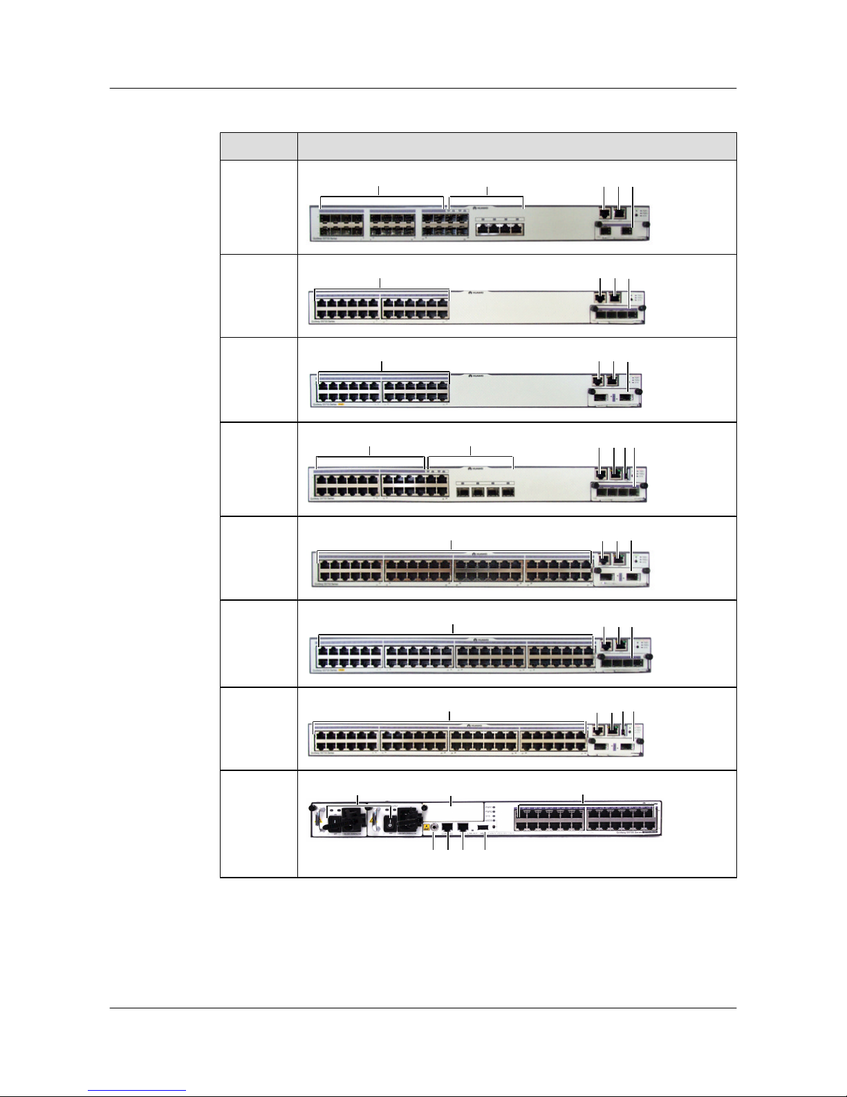
Table 1-3 S5700C front views
Model Image
S5700-28C
-EI-24S
2 5 6 711
S5700-28C
-EI
3 5 6 7
S5700-28C
-PWR-EI
3 5 6 7
S5700-28C
-SI
5 6 7812 2
S5700-52C
-EI
4 5 6 7
S5700-52C
-PWR-EI
4
5 6 7
S5700-52C
-SI
4
5 6 7
8
S5700-28C
-HI
9
7 3
10 5 6 8
S5700&S5710 Series Ethernet Switches
Hardware Description 1 Overview of the S5700
Issue 01 (2012-03-15) Huawei Proprietary and Confidential
Copyright © Huawei Technologies Co., Ltd.
9
Page 18
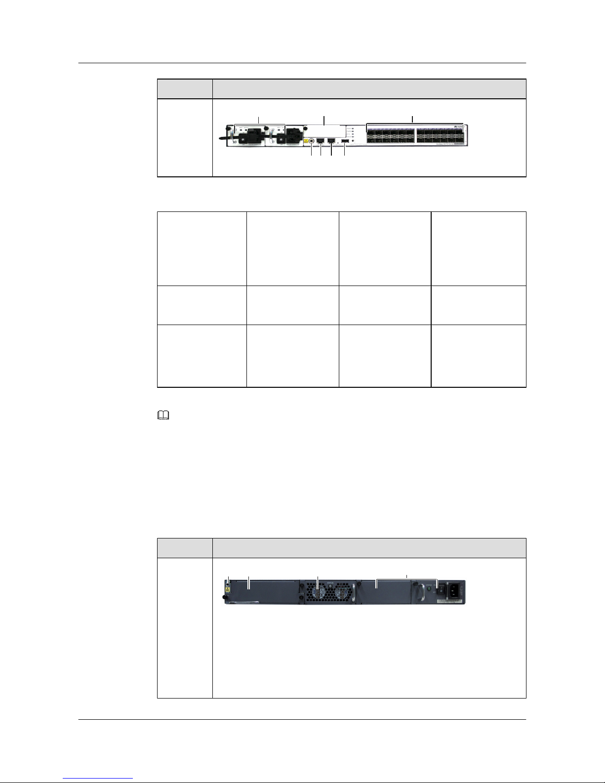
Model Image
S5700-28C
-HI-24S
9
7 1
10 5 6 8
1. Twenty-four
100/1000BASE-X
Ethernet optical
interfaces
2. Four GE combo
interfaces
(10/100/1000BASET+100/1000BASEX)
3. Twenty-four
10/100/1000BASE-T
Ethernet interfaces
4. Forty-eight
10/100/1000BASE-T
Ethernet interfaces
5. One console
interface
6. One management
interface
7. Front subcard slot 8. One USB interface
9. Power supply unit
slot
10. ESD jack 11. Twenty
100/1000BASE-X
Ethernet optical
interfaces
12. Twenty
10/100/1000BASE-T
Ethernet interfaces
NOTE
By default, a combo interface works in the auto mode. In the auto mode, if the electrical interface is
connected to a network cable first, the combo interface works as an electrical interface to transmit data; if
the optical interface is connected to a fiber first, the combo interface works as an optical interface to transmit
data.
S5700-28C-EI-24S support 1000BASE-T Copper SFP Transceiver.
Table 1-4 shows the rear views of S5700C.
Table 1-4 S5700C rear views
Model
Image
S5700-28C
-EI-24S
S5700-28C
-EI
S5700-28C
-SI
S5700-52C
-EI
S5700-52C
-SI
21 3 4
S5700&S5710 Series Ethernet Switches
Hardware Description 1 Overview of the S5700
Issue 01 (2012-03-15) Huawei Proprietary and Confidential
Copyright © Huawei Technologies Co., Ltd.
10
Page 19
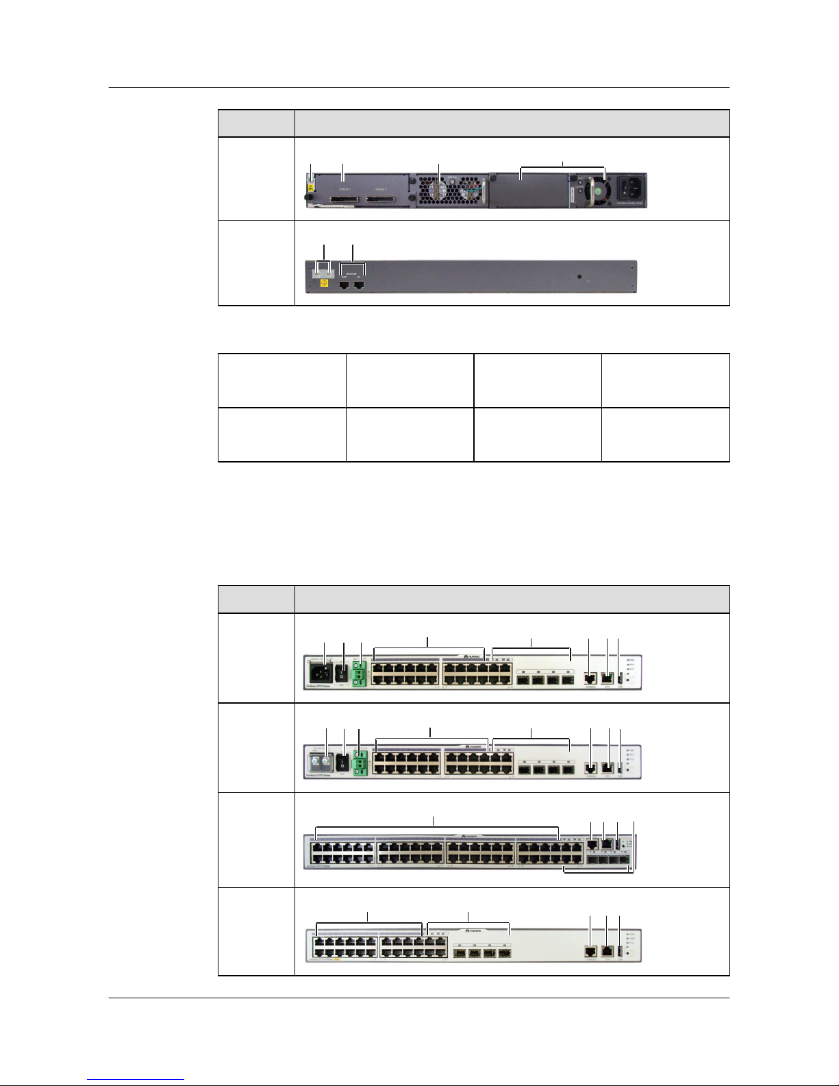
Model Image
S5700-28C
-PWR-EI
S5700-52C
-PWR-EI
21 3 4
S5700-28C
-HI
S5700-28C
-HI-24S
56
1. ESD jack
2. Rear subcard slot 3. Fan module 4. Power supply unit
slot
5. Two monitor
interfaces
6. Two ground screws
S5700TP Appearances
Table 1-5 shows the front views of S5700TP.
Table 1-5 S5700TP front views
Model
Image
S5700-24T
P-SI-AC
7 9 10 4 5 61 3
S5700-24T
P-SI-DC
8 9 10 4 5 61 3
S5700-48T
P-SI-AC
S5700-48T
P-SI-DC
42 5 6 3
S5700-24T
P-PWR-SI
4 5 61 3
S5700&S5710 Series Ethernet Switches
Hardware Description 1 Overview of the S5700
Issue 01 (2012-03-15) Huawei Proprietary and Confidential
Copyright © Huawei Technologies Co., Ltd.
11
Page 20
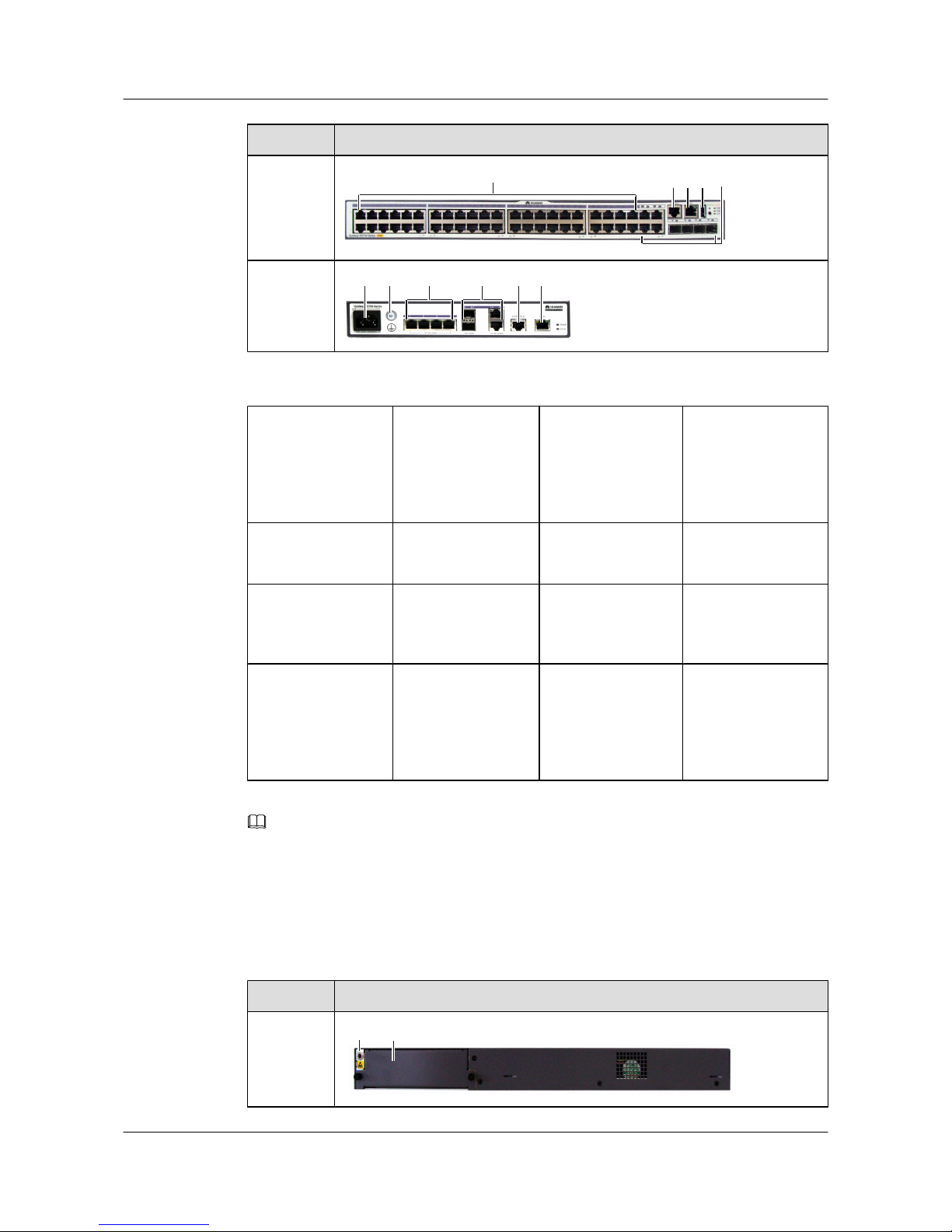
Model Image
S5700-48T
P-PWR-SI
42 5 6 3
S5700-6TP
-LI-AC
11 127 13 4 5
1. Twenty
10/100/1000BASE-T
Ethernet interfaces
2. Forty-four
10/100/1000BASE-T
Ethernet interfaces
3. Four GE combo
interfaces
(10/100/1000BASET+100/1000BASEX)
4. One console
interface
5. One management
interface
6. One USB interface 7. AC jack 8. DC jack
9. Switch 10. RPS power jack 11. Ground screw 12. Four
10/100/1000BASE-T
Ethernet interfaces
13. Two 1000M
combo interfaces
(10/100/1000BASET+100/1000BASEX)
NOTE
By default, a combo interface works in the auto mode. In the auto mode, if the electrical interface is
connected to a network cable first, the combo interface works as an electrical interface to transmit data; if
the optical interface is connected to a fiber first, the combo interface works as an optical interface to transmit
data.
Table 1-6 shows the rear views of S5700TP.
Table 1-6 S5700TP rear views
Model
Image
S5700-24T
P-SI-AC
S5700-24T
P-SI-DC
1 2
S5700&S5710 Series Ethernet Switches
Hardware Description 1 Overview of the S5700
Issue 01 (2012-03-15) Huawei Proprietary and Confidential
Copyright © Huawei Technologies Co., Ltd.
12
Page 21
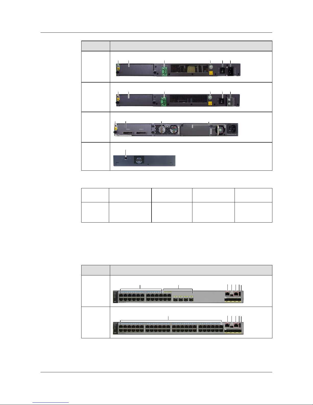
Model Image
S5700-48T
P-SI-AC
21 3 4 5 6
S5700-48T
P-SI-DC
21 3 4 5 7
S5700-24T
P-PWR-SI
S5700-48T
P-PWR-SI
21 8 9
S5700-6TP
-LI-AC
10
1. ESD jack
2. Rear subcard slot 3. RPS power jack 4. Ground screw 5. Switch
6. AC jack 7. DC jack 8. Fan module 9. Power supply
unit slot
10. Security lock
S5710C Appearances
Table 1-7 shows the front views of S5710C.
Table 1-7 S5710C front views
Model
Image
S5710-28C
-EI
1
34567
2
S5710-52C
-EI
8
34567
S5700&S5710 Series Ethernet Switches
Hardware Description 1 Overview of the S5700
Issue 01 (2012-03-15) Huawei Proprietary and Confidential
Copyright © Huawei Technologies Co., Ltd.
13
Page 22
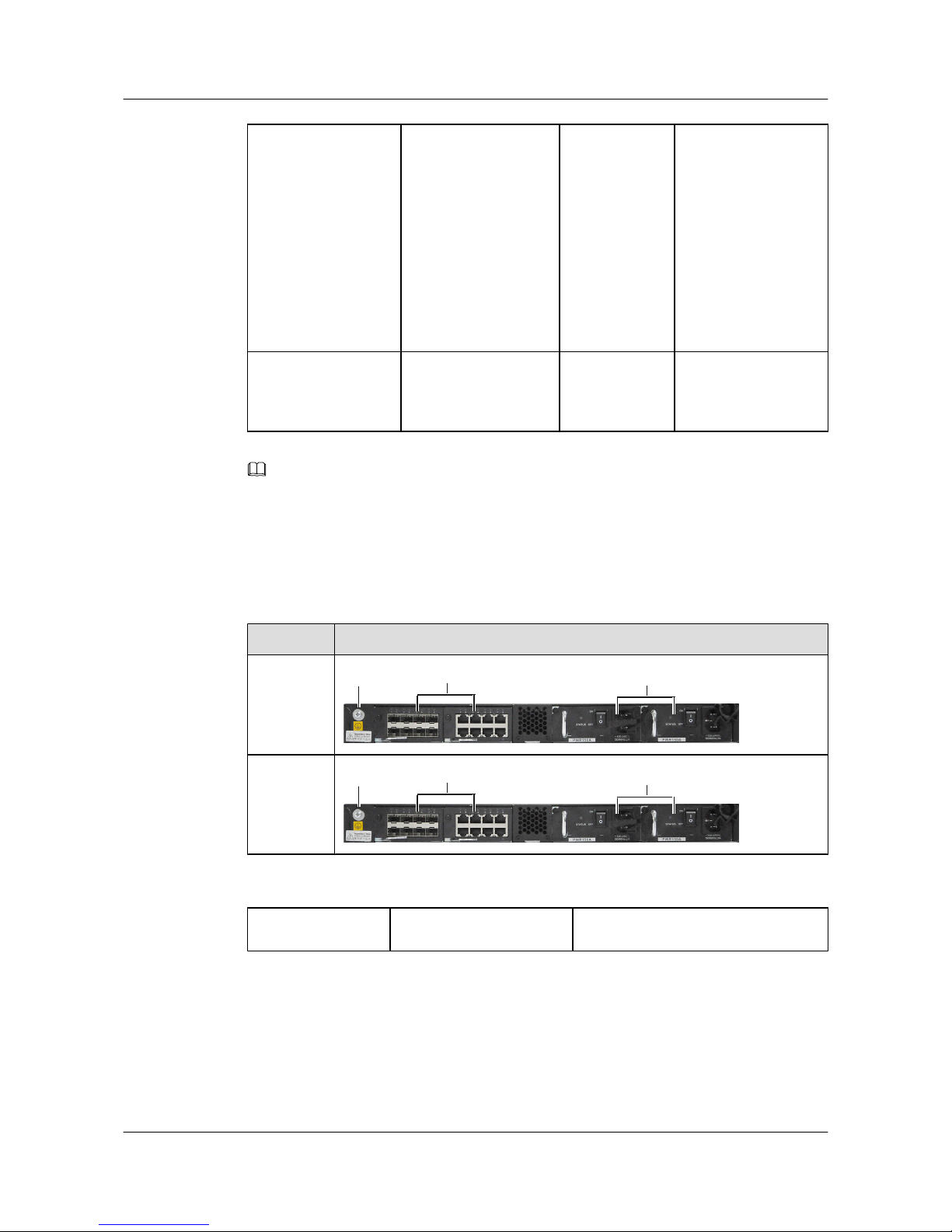
1. Twenty
10/100/1000BASE-T
Ethernet interfaces
2. Four GE combo
interfaces
(10/100/1000BASE-T
+100/1000BASE-X)
3. Four 10 Gbit/s
SFP+ uplink
optical
interfaces. These
interfaces work
in auto-sensing
mode and
automatically
change to GE
optical
interfaces.
4. One USB interface
5. One console
interface (RJ45)
6. One USB console
interface (mini USB)
7. One
management
interface
8. Forty-eight
10/100/1000BASE-T
Ethernet interfaces
NOTE
By default, a combo interface works in the auto mode. In the auto mode, if the electrical interface is
connected to a network cable first, the combo interface works as an electrical interface to transmit data; if
the optical interface is connected to a fiber first, the combo interface works as an optical interface to transmit
data.
Table 1-8 shows the rear views of S5710C.
Table 1-8 S5710C rear views
Model
Image
S5710-28C
-EI
2
1
3
S5710-52C
-EI
2
1
3
1. Ground screw
2. Two rear card slots 3. Two power supply unit slots
S5700P Appearances
Table 1-9 shows the front views of S5700P.
S5700&S5710 Series Ethernet Switches
Hardware Description 1 Overview of the S5700
Issue 01 (2012-03-15) Huawei Proprietary and Confidential
Copyright © Huawei Technologies Co., Ltd.
14
Page 23
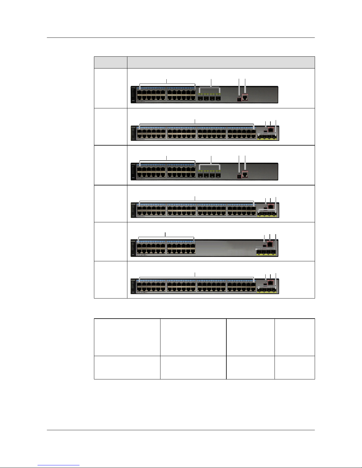
Table 1-9 S5700P front views
Model Image
S5700-28P
-LI-AC
S5700-28P
-LI-DC
45
3
1
S5700-52P
-LI-AC
S5700-52P
-LI-DC
425
3
S5700S-28
P-LI-AC
45
3
1
S5700S-52
P-LI-AC
425
3
S5700-28P
-PWR-LIAC
45 3
1
S5700-52P
-PWR-LIAC
425
3
1. Twenty-four
10/100/1000BASE-T
Ethernet interfaces
2. Forty-eight
10/100/1000BASE-T
Ethernet interfaces
3. Four
1000BASE-X
Ethernet optical
interfaces
4. One console
interface
(RJ45)
5. One USB console
interface (mini USB)
Table 1-10 shows the rear views of S5700P.
S5700&S5710 Series Ethernet Switches
Hardware Description 1 Overview of the S5700
Issue 01 (2012-03-15) Huawei Proprietary and Confidential
Copyright © Huawei Technologies Co., Ltd.
15
Page 24
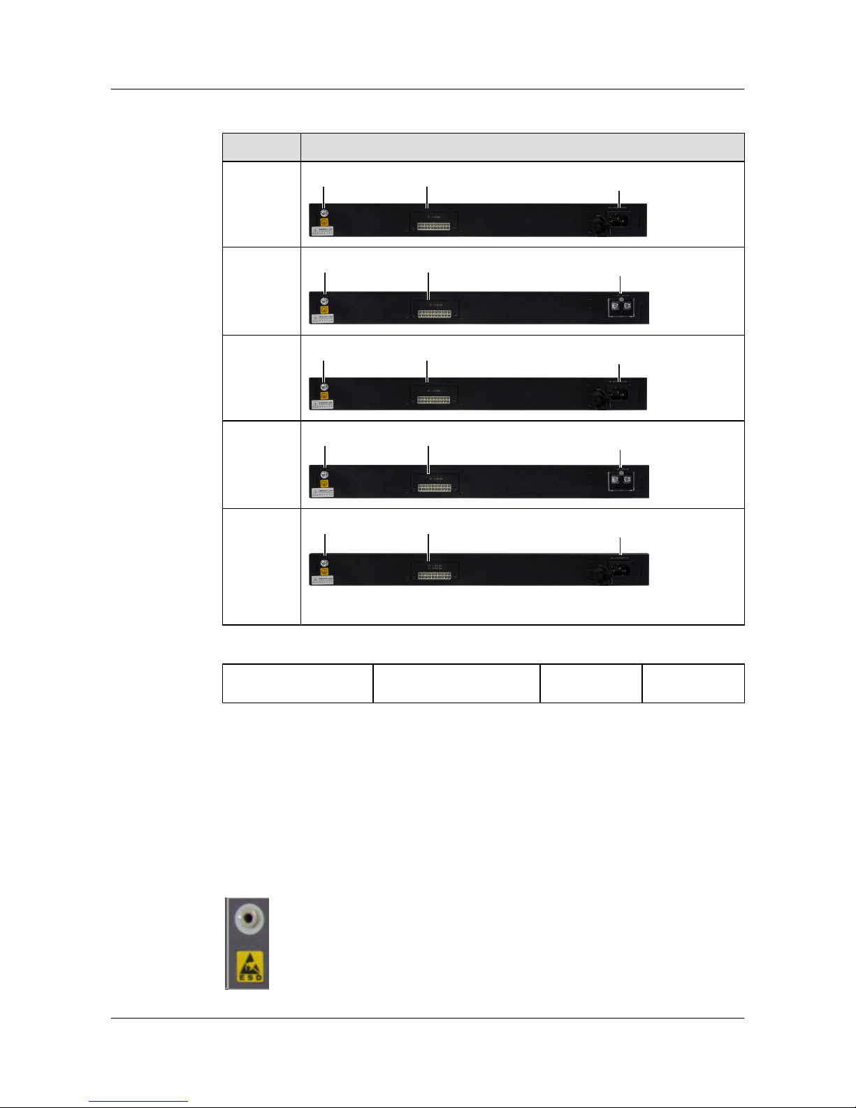
Table 1-10 S5700P rear views
Model Image
S5700-28P
-LI-AC
S5700S-28
P-LI-AC
21
3
S5700-28P
-LI-DC
21
4
S5700-52P
-LI-AC
S5700S-52
P-LI-AC
21
3
S5700-52P
-LI-DC
21
4
S5700-28P
-PWR-LIAC
S5700-52P
-PWR-LIAC
21
3
1. Ground screw
2. RPS power jack 3. AC jack 4. DC jack
1.4 ESD Jack
This section describes the functions of the ESD jack on the S5700.
The S5700 has an electromagnetic discharge (ESD) jack on the chassis.
When installing the S5700, wear an ESD wrist strap. Connect the ESD wrist strap to the ESD
jack on the chassis, as shown in Figure 1-2.
Figure 1-2 ESD jack
S5700&S5710 Series Ethernet Switches
Hardware Description 1 Overview of the S5700
Issue 01 (2012-03-15) Huawei Proprietary and Confidential
Copyright © Huawei Technologies Co., Ltd.
16
Page 25

1.5 System Configuration
Table 1-11 System configuration
Item Parameter
Processor S5700C-EI: 533 MHz
S5700C-SI: 800 MHz
S5700TP-SI: 800 MHz
S5700C-HI: 1GHz
S5700-6TP-LI-AC: 1GHz
S5700-LI: 1GHz
S5700S-LI: 1GHz
S5710EI: 1GHz
Switching capacity
l S5700-24TP: 48 Gbit/s
l S5700-28C-SI/EI/HI: 128 Gbit/s
l S5700-48TP: 96 Gbit/s
l S5700-52C-SI/EI: 176 Gbit/s
l S5700-6TP-LI-AC: 12Gbit/s
l S5700-28P-LI: 56Gbit/s
l S5700-52P-LI: 104Gbit/s
l S5700S-28P-LI: 56Gbit/s
l S5700S-52P-LI: 104Gbit/s
l S5710-28C-EI: 208Gbit/s
l S5710-52C-EI: 256Gbit/s
Packet forwarding
capacity
l S5700-24TP: 35.71 Mpps
l S5700-28C-SI/EI/HI: 95.2 Mpps
l S5700-48TP: 71.42 Mpps
l S5700-52C-SI/EI: 130.94 Mpps
l S5700-6TP-LI-AC: 8.9Mpps
l S5700-28P-LI: 41.66Mpps
l S5700-52P-LI: 77.4Mpps
l S5700S-28P-LI: 41.66Mpps
l S5700S-52P-LI: 77.4Mpps
l S5710-28C-EI: 154.7Mpps
l S5710-52C-EI: 190.5Mpps
DDR memory
512M for S5700C-HI, S5700-6TP-LI-AC and S5710EI, and 256 MB
for others
S5700&S5710 Series Ethernet Switches
Hardware Description 1 Overview of the S5700
Issue 01 (2012-03-15) Huawei Proprietary and Confidential
Copyright © Huawei Technologies Co., Ltd.
17
Page 26

Item Parameter
Flash Memory 64M for S5700C-HI, S5700-6TP-LI-AC, S5700-LI, S5700S-LI and
S5710EI, and 32 MB for others
S5700&S5710 Series Ethernet Switches
Hardware Description 1 Overview of the S5700
Issue 01 (2012-03-15) Huawei Proprietary and Confidential
Copyright © Huawei Technologies Co., Ltd.
18
Page 27

1.6 Physical Specifications
Table 1-12 Physical specifications
Item Description
Dimensions (width x depth x
height)
l S5700-24TP-SI-AC: 442.0 mm x 220.0 mm x 43.6
mm
l S5700-24TP-SI-DC: 442.0 mm x 220.0 mm x 43.6
mm
l S5700-28C-EI-24S: 442.0 mm x 420.0 mm x 43.6 mm
l S5700-28C-EI: 442.0 mm x 420.0 mm x 43.6 mm
l S5700-28C-PWR-EI: 442.0 mm x 420.0 mm x 43.6
mm
l S5700-28C-SI: 442.0 mm x 420.0 mm x 43.6 mm
l S5700-52C-EI: 442.0 mm x 420.0 mm x 43.6 mm
l S5700-52C-PWR-EI: 442.0 mm x 420.0 mm x 43.6
mm
l S5700-52C-SI: 442.0 mm x 420.0 mm x 43.6 mm
l S5700-48TP-SI-AC: 442.0 mm x 420.0 mm x 43.6
mm
l S5700-48TP-SI-DC: 442.0 mm x 420.0 mm x 43.6
mm
l S5700-24TP-PWR-SI: 442.0 mm x 420.0 mm x 43.6
mm
l S5700-48TP-PWR-SI: 442.0 mm x 420.0 mm x 43.6
mm
l S5700-28C-HI: 442.0 mm x 220.0 mm x 43.6 mm
l S5700-28C-HI-24S: 442.0 mm x 220.0 mm x 43.6 mm
l S5700-6TP-LI-AC: 250.0 mm x 180.0 mm x 43.6 mm
l S5700-28P-LI-AC: 442.0 mm x 220.0 mm x 43.6 mm
l S5700-52P-LI-AC: 442.0 mm x 310.0 mm x 43.6 mm
l S5700-28P-LI-DC: 442.0 mm x 220.0 mm x 43.6 mm
l S5700-52P-LI-DC: 442.0 mm x 310.0 mm x 43.6 mm
l S5700-28P-PWR-LI-AC: 442.0 mm x 310.0 mm x
43.6 mm
l S5700-52P-PWR-LI-AC: 442.0 mm x 310.0 mm x
43.6 mm
l S5700S-28P-LI-AC: 442.0 mm x 220.0 mm x 43.6
mm
l S5700S-52P-LI-AC: 442.0 mm x 310.0 mm x 43.6
mm
l S5710-28C-EI: 442.0 mm x 420.0 mm x 43.6 mm
S5700&S5710 Series Ethernet Switches
Hardware Description 1 Overview of the S5700
Issue 01 (2012-03-15) Huawei Proprietary and Confidential
Copyright © Huawei Technologies Co., Ltd.
19
Page 28
Item Description
l S5710-52C-EI: 442.0 mm x 420.0 mm x 43.6 mm
Maximum power (full
configuration)
l S5700-28C-EI: 60W
l S5700-52C-EI: 88W
l S5700-28C-EI-24S: 63W
l S5700-28C-SI: 56W
l S5700-52C-SI: 78W
l S5700-24TP-SI-AC: 40W
l S5700-24TP-SI-DC: 40W
l S5700-48TP-SI-AC: 64W
l S5700-48TP-SI-DC: 64W
l S5700-24TP-PWR-SI: 455 W (Dissipated power: 85
W, PoE: 370 W)
l S5700-48TP-PWR-SI: 907 W (Dissipated power: 167
W, PoE: 740 W)
l S5700-28C-PWR-EI: 842 W (Dissipated power: 102
W, PoE: 740 W)
l S5700-52C-PWR-EI: 930 W (Dissipated power: 190
W, PoE: 740 W)
l S5700-28C-HI: 76.6W
l S5700-28C-HI-24S: 80.7W
l S5700-6TP-LI-AC: 28.9W
l S5700-28P-LI-AC: 25.3W
l S5700-28P-LI-DC: 25.3W
l S5700-52P-LI-AC: 52W
l S5700-52P-LI-DC: 52W
l S5700-28P-PWR-LI-AC: 765.3W (Device: 25.3W,
RPS power: 740W)
l S5700-52P-PWR-LI-AC: 792W (Device: 52W, RPS
power: 740W)
l S5700S-28P-LI-AC: 25.3W
l S5700S-52P-LI-AC: 52W
l S5710-28C-EI: 100W
l S5710-52C-EI: 165W
Weight
Full
configuration
≤ 8.5 kg
Empty chassis
≤ 5 kg
DC input
voltage
Rated voltage –48V DC to –60V DC
Maximum
voltage
–36V DC to –72V DC
S5700&S5710 Series Ethernet Switches
Hardware Description 1 Overview of the S5700
Issue 01 (2012-03-15) Huawei Proprietary and Confidential
Copyright © Huawei Technologies Co., Ltd.
20
Page 29

Item Description
AC input
voltage
Rated voltage 100V AC to 240V AC
Maximum
voltage
90V AC to 264V AC
Temperature operating
temperature
S5300SI, S5300EI: 0°C to 50°C
S5700-6TP-LI-AC: -5°C to 55°C (Altitude: 0 m to 2000
m); S5700HI: -5°C to 55°C (Altitude: 0 m to 1800 m)
NOTE
For S5700HI, if using 40km SFP+ optical module, the operating
temperature of S5700HI is between -5°C and 45°C.
S5700-LI, S5700S-LI: 0°C to 45°C (Altitude: 0 m to 1800
m).When the altitude is between 1800 m and 4000 m, the
temperature limit degrades 1°C when the altitude
increases 220 m.
S5710EI: 0°C to 50°C (Altitude: 0 m to 1800 m).When
the altitude is between 1800 m and 4000 m, the
temperature limit degrades 1°C when the altitude
increases 220 m.
Storage
temperature
-40°C to 70°C
Relative humidity 10%RH to 90%RH
Altitude S5706TP-LI-AC: 0 m to 2000 m
S5700SI, S5700EI: 0 m to 2000 m
S5700HI, S5700-LI, S5700S-LI, S5710EI: 0 m to 4000 m
S5700&S5710 Series Ethernet Switches
Hardware Description 1 Overview of the S5700
Issue 01 (2012-03-15) Huawei Proprietary and Confidential
Copyright © Huawei Technologies Co., Ltd.
21
Page 30

2 Power Supply Unit
About This Chapter
This chapter describes the AC and DC power supply units of the S5700.
CAUTION
l Only the power supply units of the same power can be used on an S5700.
l Power off the S5700 before removing the power supply units. Do not operate the power
supply units when the S5700 is running.
l Before powering off the S5700, shut down all its power supply units.
2.1 Power Supply Configuration
This section describes the power supply configuration on the S5700.
2.2 Power Supply Unit Working Mode
This section describes the working mode of S5700 power supply units.
2.3 150 W DC Power Supply Units
This section describes the functions, appearance, switch, indicators, and technical specifications
of the S5700 150 W DC power supply unit.
2.4 150 W AC Power Supply Units
This section describes the functions, appearance, switch, indicators, and technical specifications
of the S5700 150 W AC power supply unit.
2.5 170 W DC Power Supply Units
This section describes the functions, appearance, switch, indicators, and technical specifications
of the S5700 170 W DC power supply unit.
2.6 170 W AC Power Supply Units
This section describes the functions, appearance, switch, indicators, and technical specifications
of the S5700 170 W AC power supply unit.
2.7 AC PoE Power Supply Units
This section describes the functions, appearance, switch, indicators, and technical specifications
of the S5700 AC PoE power supply unit.
S5700&S5710 Series Ethernet Switches
Hardware Description 2 Power Supply Unit
Issue 01 (2012-03-15) Huawei Proprietary and Confidential
Copyright © Huawei Technologies Co., Ltd.
22
Page 31

2.8 RPS1800 Power Supply Unit
This section describes the functions, appearance, indicators, and technical specifications of the
RPS1800 power supply unit connected to the S5700.
S5700&S5710 Series Ethernet Switches
Hardware Description 2 Power Supply Unit
Issue 01 (2012-03-15) Huawei Proprietary and Confidential
Copyright © Huawei Technologies Co., Ltd.
23
Page 32

2.1 Power Supply Configuration
This section describes the power supply configuration on the S5700.
PoE Power Supply
The downlink electrical interfaces of S5700 PoE switches provide PoE power. Each interface
provides a maximum of 30 W power and supports a maximum of 100 m power supply distance.
The S5700 can transmit both current and data on a pair of signal cables.
Power supply units of S5700 PoE switches can be swappable or built-in.
Swappable PoE power supply units are classified in to 500 W and 250 W.
Power Supply Unit PoE Power Device Power
500 W PoE power supply
unit
369.6 W 120 W
250 W PoE power supply
unit
123.2 W 120 W
Currently, the following S5700 switches support swappable PoE power supply units:
S5700-48TP-PWR-SI, S5700-52C-PWR-EI, S5700-24TP-PWR-SI, and S5700-28C-PWR-EI.
These switches support both swappable 500 W PoE power supply units and swappable 250 W
PoE power supply units. The power supply configurations are shown in the following table.
Power Supply Unit
PoE Power Device Maximum
Number of
Interfaces
250 W N/A 123.2 W S5700-48TP-PWR-
SI
S5700-52C-PWR-EI
S5700-28C-PWR-EI
S5700-24TP-PWRSI
l 802.3af: 8
l 802.3at: 4
500 W N/A 369.6 W S5700-48TP-PWR-
SI
S5700-52C-PWR-EI
S5700-28C-PWR-EI
S5700-24TP-PWRSI
l 802.3af: 24
l 802.3at: 12
S5700&S5710 Series Ethernet Switches
Hardware Description 2 Power Supply Unit
Issue 01 (2012-03-15) Huawei Proprietary and Confidential
Copyright © Huawei Technologies Co., Ltd.
24
Page 33
Power Supply Unit PoE Power Device Maximum
Number of
Interfaces
250 W 250 W 246.4 W S5700-48TP-PWR-
SI
S5700-52C-PWR-EI
S5700-28C-PWR-EI
S5700-24TP-PWRSI
l 802.3af: 16
l 802.3at: 8
500 W 500 W 739.2 W S5700-48TP-PWR-
SI
S5700-52C-PWR-EI
l 802.3af: 48
l 802.3at: 24
S5700-28C-PWR-EI
l 802.3af: 24
l 802.3at: 24
369.6 W S5700-24TP-PWRSI
l 802.3af: 24
l 802.3at: 12
NOTE
When two power supply units are used, they work in redundancy backup mode to provide power for the
device and in load balancing mode to provide power for PDs.
Currently, S5700-28P-PWR-LI-AC and S5700-52P-PWR-LI-AC supports built-in powers.
A 500 W PoE power is built in S5700-28P-PWR-LI-AC and S5700-52P-PWR-LI-AC. They
can also be connected to external redundant power source (RPS) power supply units. The power
supply configurations are shown in the following table.
Power Supply Unit
PoE Power Device Maximum
Number of
Interfaces
No
external
RPS power
supply unit
N/A 370 W S5700-28P-PWR-LI-
AC
S5700-52P-PWR-LIAC
l 802.3af: 24
l 802.3at: 12
External
RPS power
supply unit
N/A 740 W S5700-28P-PWR-LI-
AC
l 802.3af: 24
l 802.3at: 24
S5700-52P-PWR-LIAC
l 802.3af: 48
l 802.3at: 24
Non-PoE Power Supply Configuration
On a non-PoE switch, one or two power supply units can be configured.
S5700&S5710 Series Ethernet Switches
Hardware Description 2 Power Supply Unit
Issue 01 (2012-03-15) Huawei Proprietary and Confidential
Copyright © Huawei Technologies Co., Ltd.
25
Page 34
When two power supply units are used, they work in 1:1 backup mode to provide power for the
device.
NOTE
l The power supply units of S5700-6TP-LI-AC, S5700-24TP-SI-AC, S5700-24TP-SI-DC, S5700-48TP-
SI-AC, S5700-48TP-SI-DC, S5700-52P-LI-AC, S5700-52P-LI-DC, S5700S-52P-LI-AC, S5700-28PLI-AC, S5700-28P-LI-DC, S5700S-28P-LI-AC, S5700-28P-PWR-LI-AC and S5700-52P-PWR-LIAC are not hot swappable.
l The S5700-24TP-SI-AC, S5700-24TP-SI-DC, S5700-48TP-SI-AC, S5700-48TP-SI-DC, S5700-52P-
LI-AC, S5700-52P-LI-DC, S5700S-52P-LI-AC, S5700-28P-LI-AC, S5700-28P-LI-DC, S5700S-28PLI-AC, S5700-28P-PWR-LI-AC and S5700-52P-PWR-LI-AC support redundancy power supply
(RPS).
l The AC power supply and the DC power supply can be configured on an S5700-28C-HI or S5700-28C-
HI-24S.
2.2 Power Supply Unit Working Mode
This section describes the working mode of S5700 power supply units.
2.2.1 Working Mode of DC Power Supply Units
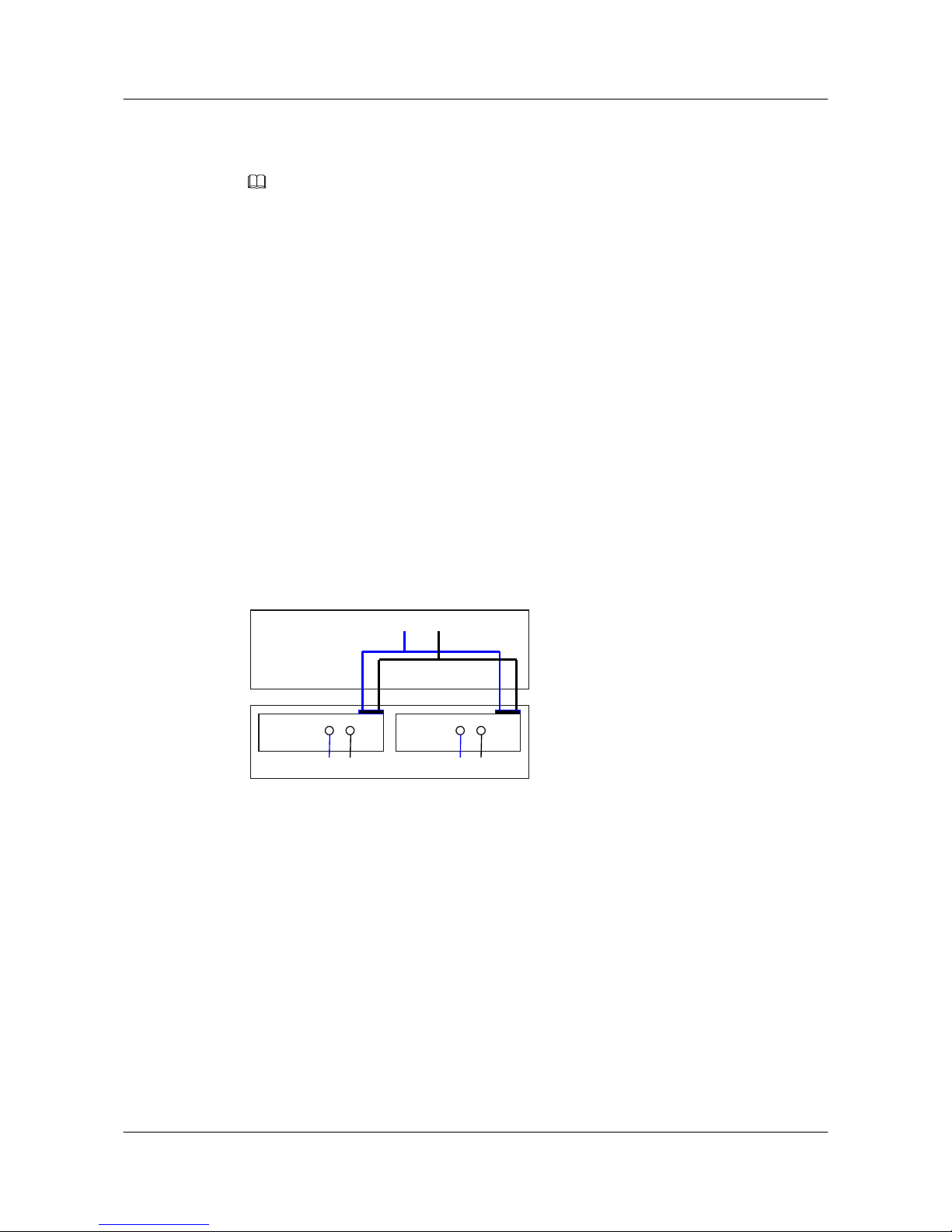
The working mode of the S5700 DC power supply units is shown in Figure 2-1.
Figure 2-1 Working mode of DC power supply units
PWR1
NEG RTN
Motherboard
GND12V
PWR2
NEG RTN
NEG: Power cable
RTN: Ground cable GND: Grounding
After the DC power is transmitted to the PWR module, the PWR module outputs 12 V voltage,
and then the motherboard provides power for the entire device.
2.2.2 Working Mode of Non-PoE AC Power Supply Units
The working mode of the S5700 Non-PoE AC power supply units is shown in Figure 2-2 and
Figure 2-3.
S5700&S5710 Series Ethernet Switches
Hardware Description 2 Power Supply Unit
Issue 01 (2012-03-15) Huawei Proprietary and Confidential
Copyright © Huawei Technologies Co., Ltd.
26
Page 35
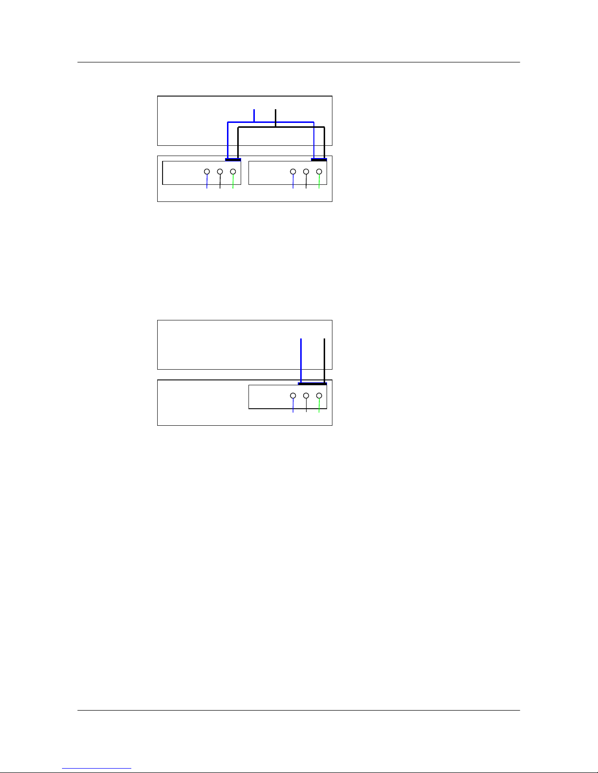
Figure 2-2 Working mode of Non-PoE AC power supply units
PWR1
L N
Motherboard
GND12V
PGND
PWR2
L N PGND
L: Live line N: Neutral wire PGND: PGND cable GND: Grounding
After the AC power is transmitted to the PWR module except S5700-6TP-LI-AC, S5700-24TPSI-AC, S5700-48TP-SI-AC, S5700-52P-LI-AC, S5700S-52P-LI-AC, S5700-28P-LI-AC and
S5700S-28P-LI-AC, the PWR module outputs 12 V voltage, and then the motherboard provides
power for the entire device.
Figure 2-3 Working mode of a non-PoE AC power supply unit that functions alone
Motherboard
GND12V
PWR1
L N PGND
L: Live line
N: Neutral wire PGND: PGND cable GND: Grounding
on the S5700-6TP-LI-AC, S5700-24TP-SI-AC, S5700-48TP-SI-AC, S5700-52P-LI-AC,
S5700S-52P-LI-AC, S5700-28P-LI-AC and S5700S-28P-LI-AC, after the AC power is
transmitted to the PWR module, the PWR module outputs 12 V voltage, and provides power for
the entire device.
2.2.3 Working Mode of PoE AC Power Supply Units
The working mode of S5700 PoE AC power supply units is shown in Figure 2-4 and Figure
2-5.
S5700&S5710 Series Ethernet Switches
Hardware Description 2 Power Supply Unit
Issue 01 (2012-03-15) Huawei Proprietary and Confidential
Copyright © Huawei Technologies Co., Ltd.
27
Page 36
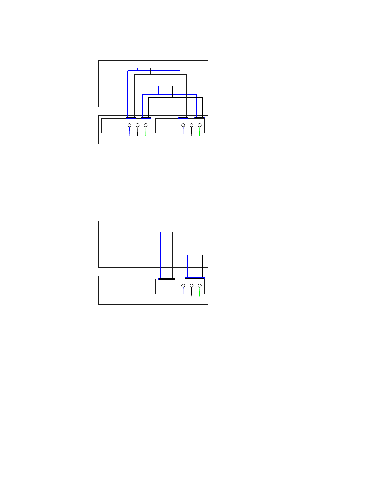
Figure 2-4 Working mode of two PoE AC power supply units
PWR1
L N
Motherboard
GND12V
PGND
PWR2
L N PGND
-53V RTN
L: Live line N: Neutral wire PGND: PGND cable GND: Grounding RTN: Ground cable
After the PoE power is transmitted to the PWR module except S5700-28P-PWR-LI-AC and
S5700-52P-PWR-LI-AC, the PWR module outputs 12 V and -53 V voltage, and then the
motherboard provides 12 V voltage for the entire device and -53 V voltage for the powered
devices (PDs).
Figure 2-5 Working mode of a PoE AC power supply unit
Motherboard
GND
12V
PWR1
L N PGND
-53V RTN
L: Live line
N: Neutral wire PGND: PGND cable GND: Grounding RTN: Ground cable
S5700-28P-PWR-LI-AC and S5700-52P-PWR-LI-AC have built-in PoE power supply units,
which provides a channel of 12 V voltage and a channel of -53 V voltage. The 12 V voltage is
provided for the entire device, and the -53 V voltage is provided for the PDs.
2.3 150 W DC Power Supply Units
This section describes the functions, appearance, switch, indicators, and technical specifications
of the S5700 150 W DC power supply unit.
2.3.1 Function Overview
The 150 W DC power supply unit provides +12 V DC power. It has the following functions:
S5700&S5710 Series Ethernet Switches
Hardware Description 2 Power Supply Unit
Issue 01 (2012-03-15) Huawei Proprietary and Confidential
Copyright © Huawei Technologies Co., Ltd.
28
Page 37
l EMC filtering, surge protection, and short circuit protection.
l Various alarms, for example, the alarm triggered when there is no power input, the alarm
for air breaker status, the alarm for invalid surge protection, and the alarm for undervoltage
input.
Applications
Only S5710-28C-EI, S5710-52C-EI, S5700-28C-EI, S5700-28C-EI-24S, S5700-52C-EI,
S5700-28C-SI, and S5700-52C-SI support the 150 W DC power supply unit.
2.3.2 Panel
NOTE
l The power supply units of S5700-52P-LI-DC, S5700-28P-LI-DC, S5700-24TP-SI-DC and
S5700-48TP-SI-DC are integrated on the switch control unit (SCU). They do not support power
modules. The functions of the power supply unit switch are the same as the functions of the power
module switch.
l The power supply units of S5700-52P-LI-DC, S5700-28P-LI-DC, S5700-24TP-SI-DC and
S5700-48TP-SI-DC do not have the status indicators. For the status and meanings of power indicators,
see the PWR indicator description in section 6.1 Indicators on the Front Panel.
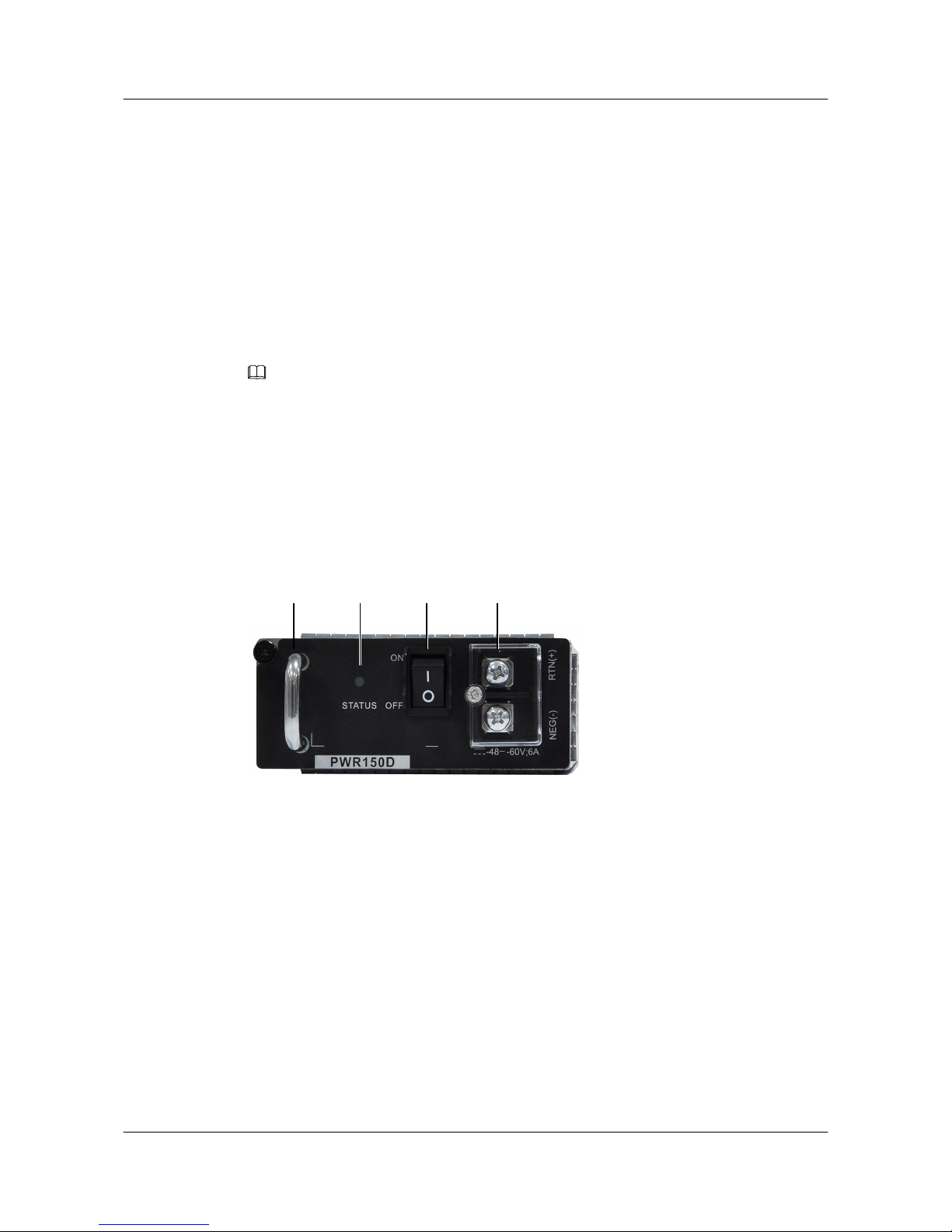
Figure 2-6 shows the appearance of the 150 W DC power supply unit.
Figure 2-6 Appearance of the 150 W DC power supply unit
1 2 3 4
1. Handle
2. Indicator 3. Switch 4. DC jack
Table 2-1 describes the meanings of the indicator.
S5700&S5710 Series Ethernet Switches
Hardware Description 2 Power Supply Unit
Issue 01 (2012-03-15) Huawei Proprietary and Confidential
Copyright © Huawei Technologies Co., Ltd.
29
Page 38

Table 2-1 Description of the 150 W DC power indicators
Name Status Description
STATUS Off
l The input power is out of
range, for example, no
DC input power, DC
input overvoltage, and
DC input undervoltage.
l The output power is out of
range, for example,
undervoltage or
overtemperature occurs.
Green
The DC input power is within
range.
Blinking green The output power is out of
range, for example,
overvoltage, overcurrent, or
short circuit occurs.
2.3.3 Technical Specifications
Table 2-2 describes the technical specifications of the 150 W DC power supply unit.
Table 2-2 Technical specifications of the DC power supply unit
Item
S5700-2
8C-EI
S5700-28
C-EI-24S
S5700-2
8C-SI
S5700-5
2C-EI
S5700-5
2C-SI
S5710-2
8C-EI
S5710-5
2C-EI
Dimensio
ns (width
x depth x
height)
100 mm x 220 mm x 43 mm
Weight 0.8 kg
Rated
input
voltage
-60 V DC to -48 V DC
Maximu
m input
voltage
-72 V DC to -36 V DC
Maximu
m input
current
6 A
S5700&S5710 Series Ethernet Switches
Hardware Description 2 Power Supply Unit
Issue 01 (2012-03-15) Huawei Proprietary and Confidential
Copyright © Huawei Technologies Co., Ltd.
30
Page 39
Item S5700-2
8C-EI
S5700-28
C-EI-24S
S5700-2
8C-SI
S5700-5
2C-EI
S5700-5
2C-SI
S5710-2
8C-EI
S5710-5
2C-EI
Maximu
m output
current
12.5 A
Maximu
m output
power
150 W
2.4 150 W AC Power Supply Units
This section describes the functions, appearance, switch, indicators, and technical specifications
of the S5700 150 W AC power supply unit.
2.4.1 Function Overview
The 150 W AC power supply unit provides the EMC filtering function and protects the device
against:
l Output overcurrent
l Output overvoltage
l Output undervoltage
l Input overvoltage
l Input undervoltage
l Overtemperature
l Short circuit
l Lightning
Applications
Only S5710-28C-EI, S5710-52C-EI, S5700-28C-EI, S5700-28C-EI-24S, S5700-52C-EI,
S5700-28C-SI, and S5700-52C-SI support the 150 W AC power supply unit.
2.4.2 Panel
NOTE
l The power supply units of S5700-52P-LI-AC, S5700-28P-LI-AC, S5700S-52P-LI-AC, S5700S-28P-
LI-AC, S5700-24TP-SI-AC and S5700-48TP-SI-AC are integrated on the switch control unit (SCU).
They do not support power modules. The functions of the power supply unit switch are the same as
the functions of the power module switch.
l The power supply units of S5700-52P-LI-AC, S5700-28P-LI-AC, S5700S-52P-LI-AC, S5700S-28P-
LI-AC, S5700-24TP-SI-AC and S5700-48TP-SI-AC do not have the status indicators. For the status
and meanings of power indicators, see the PWR indicator description in section 6.1 Indicators on the
Front Panel.
Figure 2-7 shows the appearance of the 150 W AC power supply unit.
S5700&S5710 Series Ethernet Switches
Hardware Description 2 Power Supply Unit
Issue 01 (2012-03-15) Huawei Proprietary and Confidential
Copyright © Huawei Technologies Co., Ltd.
31
Page 40
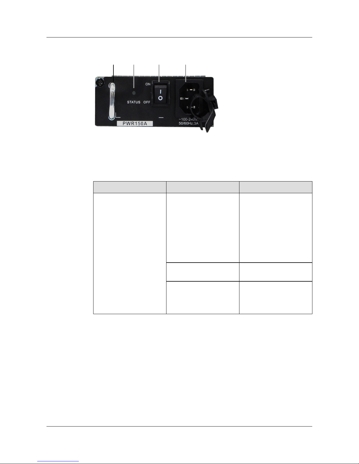
Figure 2-7 Appearance of the 150 W AC power supply unit
1 2 3 4
1. Handle 2. Indicator 3. Switch 4. AC jack
Table 2-3 describes the meanings of the indicator.
Table 2-3 Description of the 150 W AC power indicators
Name Status Description
STATUS Off
l The input power is out of
range, for example, no
AC input power, AC
input overvoltage, and
AC input undervoltage.
l The output power is out of
range, for example,
undervoltage or
overtemperature occurs.
Green
The AC input power is within
range.
Blinking green The output power is out of
range, for example,
overvoltage, overcurrent, or
short circuit occurs.
2.4.3 Technical Specifications
Table 2-4 describes the technical specifications of the 150 W AC power supply unit.
S5700&S5710 Series Ethernet Switches
Hardware Description 2 Power Supply Unit
Issue 01 (2012-03-15) Huawei Proprietary and Confidential
Copyright © Huawei Technologies Co., Ltd.
32
Page 41

Table 2-4 Technical specifications of the 150 W AC power supply unit
Item S5700-2
8C-EI
S5700-28
C-EI-24S
S5700-2
8C-SI
S5700-5
2C-EI
S5700-5
2C-SI
S5710-2
8C-EI
S5710-5
2C-EI
Dimensio
ns (width
x depth x
height)
100 mm x 220 mm x 43 mm
Weight 0.8 kg
Rated
input
voltage
100 V AC to 240 V AC, 50/60 Hz
Maximu
m input
voltage
90 V AC to 264 V AC, 47 Hz to 63 Hz
Maximu
m input
current
3 A
Maximu
m output
current
12.5 A
Maximu
m output
power
150 W
2.5 170 W DC Power Supply Units
This section describes the functions, appearance, switch, indicators, and technical specifications
of the S5700 170 W DC power supply unit.
2.5.1 Function Overview
The 170 W DC power supply units are used on S5700-28C-HI and S5700-28C-HI-24S. A power
supply unit provides +12 V DC power, and it has the following functions:
l EMC filtering and surge protection
l Protection against reversed connection, input and output overcurrent, input and output
overvoltage, short circuit, and overtemperature
l Various alarms, for example, the alarm triggered when there is no power input or output
NOTE
Only S5700-28C-HI and S5700-28C-HI-24S support the 170 W DC power supply unit.
S5700&S5710 Series Ethernet Switches
Hardware Description 2 Power Supply Unit
Issue 01 (2012-03-15) Huawei Proprietary and Confidential
Copyright © Huawei Technologies Co., Ltd.
33
Page 42
Applications
Only S5700-28C-HI and S5700-28C-HI-24S support the 170 W DC power supply unit.
2.5.2 Panel
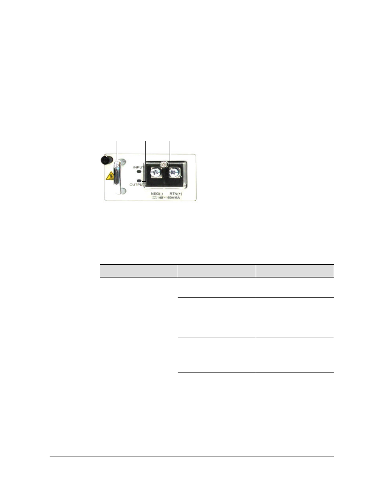
Figure 2-8 shows the appearance of the 170 W DC power supply unit.
Figure 2-8 Appearance of the 170 W DC power supply unit
1 2 3
1. Handle 2. Indicator 3. DC jack
Table 2-5 describes the meanings of the indicators.
Table 2-5 Description of the 170 W DC power indicators
Name
Status Description
INPUT Green The DC input power is within
range.
Off The DC input power is out of
range or no DC input power.
OUTPUT Green The DC output power is
within range.
Blinking green The output power is out of
range, for example,
overvoltage, overcurrent, or
short circuit occurs.
Off The DC output power is out
of range.
2.5.3 Technical Specifications
Table 2-6 describes the technical specifications of the 170 W DC power supply unit.
S5700&S5710 Series Ethernet Switches
Hardware Description 2 Power Supply Unit
Issue 01 (2012-03-15) Huawei Proprietary and Confidential
Copyright © Huawei Technologies Co., Ltd.
34
Page 43

Table 2-6 Technical specifications of the 170 W DC power supply unit
Item S5700-28C-HI S5700-28C-HI-24S
Dimensions (width x depth x height) 60.0 mm x 195.4 mm x 40.0 mm
Weight < 0.8 kg
Rated input voltage range -60 V DC to -48 V DC
Maximum input voltage range -72 V DC to -36 V DC
Maximum input current 6 A
Maximum output current 14.2 A
Rated output voltage 12 V
Maximum output power 170 W
2.6 170 W AC Power Supply Units
This section describes the functions, appearance, switch, indicators, and technical specifications
of the S5700 170 W AC power supply unit.
2.6.1 Function Overview
170 W AC power supply units are used on S5700-28C-HI and S5700-28C-HI-24S. A power
supply unit provides +12 V AC power, and it has the following functions:
l EMC filtering and surge protection
l Protection against reversed connection, input and output overcurrent, input and output
overvoltage, short circuit, and overtemperature
l Various alarms, for example, the alarm triggered when there is no power input or output
Applications
Only S5700-28C-HI and S5700-28C-HI-24S support the 170 W AC power supply unit.
2.6.2 Panel
Figure 2-9 shows the appearance of the 170 W AC power supply unit.
S5700&S5710 Series Ethernet Switches
Hardware Description 2 Power Supply Unit
Issue 01 (2012-03-15) Huawei Proprietary and Confidential
Copyright © Huawei Technologies Co., Ltd.
35
Page 44
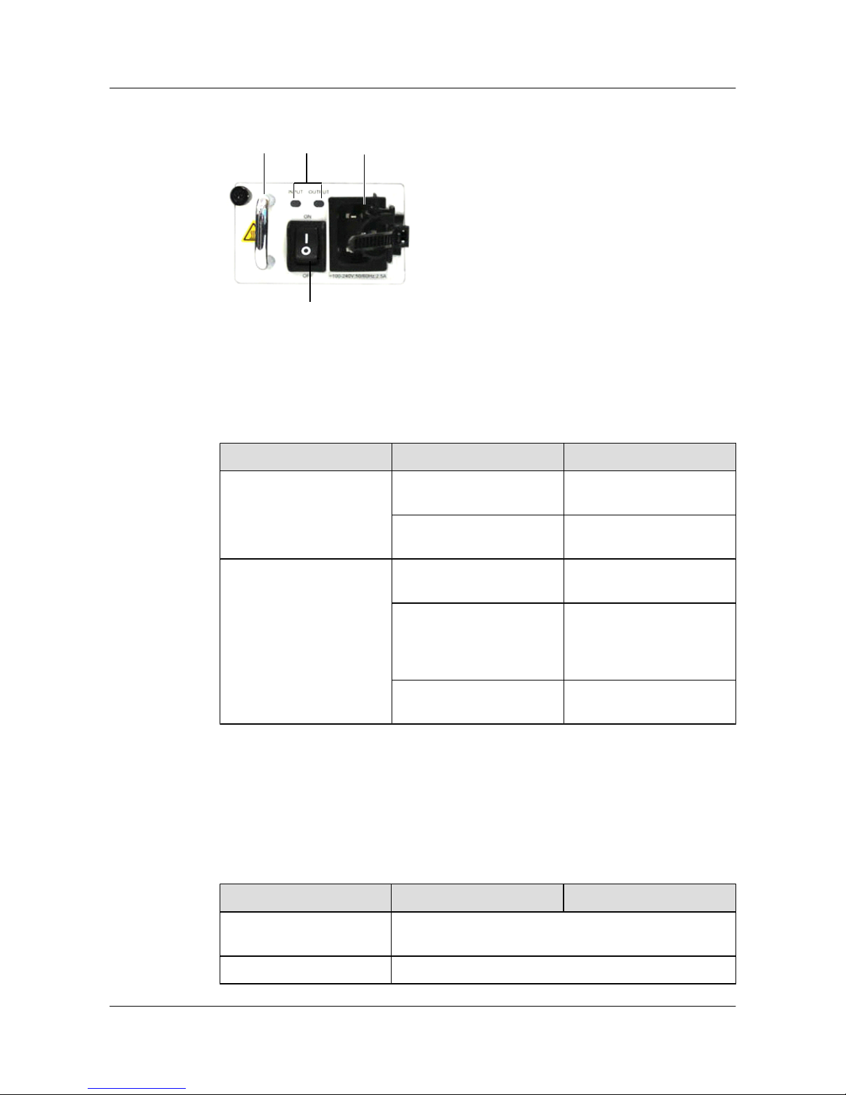
Figure 2-9 Appearance of the 170 W AC power supply unit
1 2
3
4
1. Handle 2. Indicator 3. Switch 4. AC jack
Table 2-7 describes the meanings of the indicators.
Table 2-7 Description of the 170 W AC power indicators
Name Status Description
INPUT Green The AC input power is within
range.
Off The AC input power is out of
range or no AC input power.
OUTPUT Green The AC output power is
within range.
Blinking green The output power is out of
range, for example,
overvoltage, overcurrent, or
short circuit occurs.
Off The AC output power is out
of range.
2.6.3 Technical Specifications
Table 2-8 describes the technical specifications of the 170 W AC power supply unit.
Table 2-8 Technical specifications of the 170 W AC power supply unit
Item
S5700-28C-HI S5700-28C-HI-24S
Dimensions (width x depth x
height)
60.0 mm x 195.4 mm x 40.0 mm
Weight < 1.0 kg
S5700&S5710 Series Ethernet Switches
Hardware Description 2 Power Supply Unit
Issue 01 (2012-03-15) Huawei Proprietary and Confidential
Copyright © Huawei Technologies Co., Ltd.
36
Page 45

Item S5700-28C-HI S5700-28C-HI-24S
Rated input voltage range 100 V AC to 240 V AC, 50/60 Hz
Maximum input voltage
range
90 V AC to 264 V AC, 47 Hz to 63 Hz
Maximum input current 2.5 A
Maximum output current 14.2 A
Rated output voltage 12 V
Maximum output power 170 W
2.7 AC PoE Power Supply Units
This section describes the functions, appearance, switch, indicators, and technical specifications
of the S5700 AC PoE power supply unit.
2.7.1 Function Overview
Power over Ethernet (PoE) refers to power supply over a 10Base-T, 100Base-TX, or 1000BaseT twisted pair cable.
PoE provides power for terminals such as IP phones, access points (APs), portable device
chargers, point-of-sale (POS) machines, cameras, and data collectors. These terminals are
powered when they access the network, so the indoor power supply systems are not required.
Complying with IEEE 802.3af and IEEE 802.3at, the PoE S5700 is able to remotely provide
power for the devices of different vendors. IEEE 802.3af supports a maximum of 15.4 W power
and IEEE 802.3at supports a maximum of 30 W power.
The PoE function transmits power together with data to terminals over cables or transmits power
without data over idle lines. The S5700 can transmit power together with data at a rate of up to
1000 Mbit/s.
2.7.2 Panel
Two swappable PoE power supply unit types are 250 W PoE power supply units shown in
Figure 2-10, and 500 W PoE power supply units shown in Figure 2-11. The appearance of a
250 W PoE power supply unit is different from that of 500 W PoE power supply unit. The distinct
difference is the fan.
NOTE
A 500 W AC PoE power supply unit is built in S5700-28P-PWR-LI-AC and S5700-52P-PWR-LI-AC.
They do not support swappable PoE power supply units.
S5700&S5710 Series Ethernet Switches
Hardware Description 2 Power Supply Unit
Issue 01 (2012-03-15) Huawei Proprietary and Confidential
Copyright © Huawei Technologies Co., Ltd.
37
Page 46
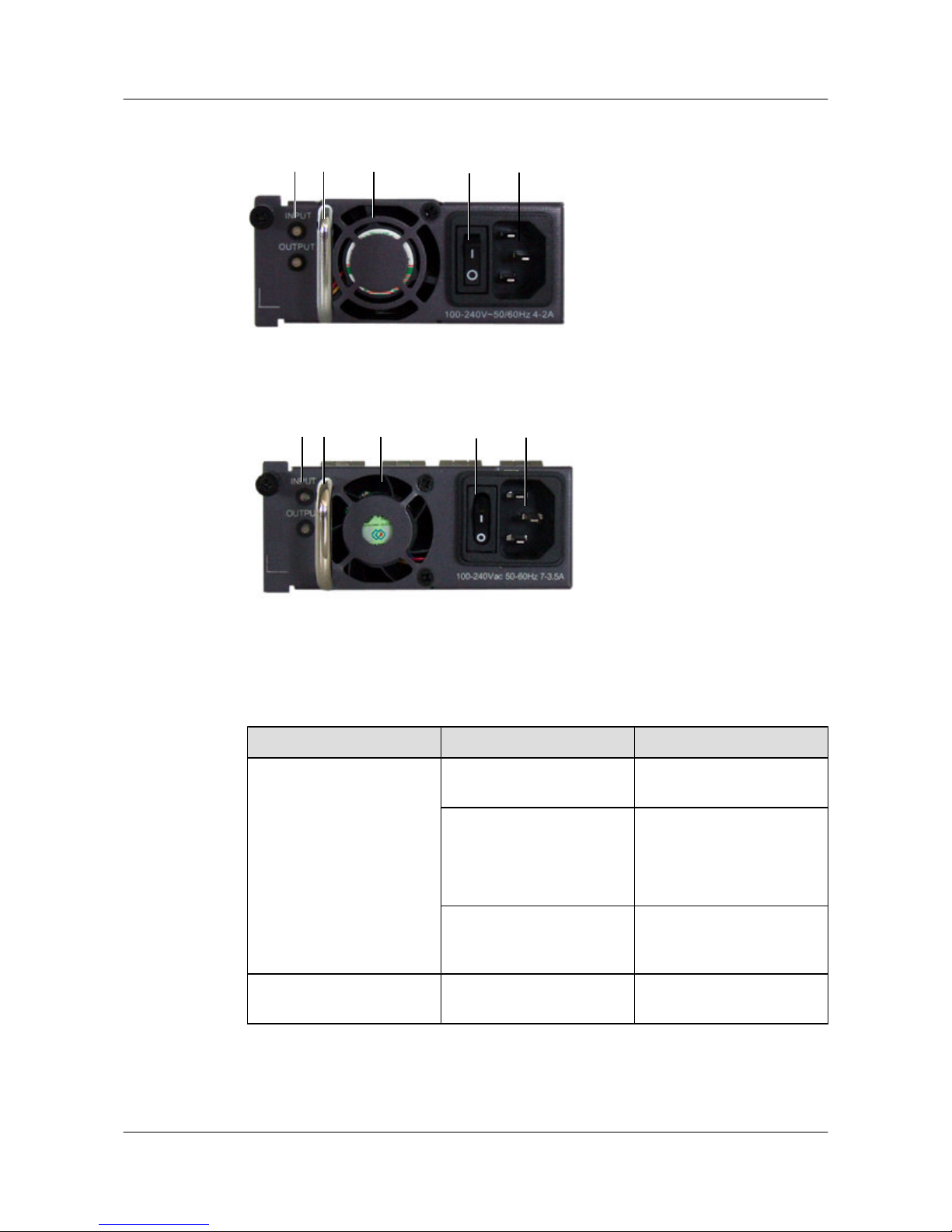
Figure 2-10 Appearance of the 250 W AC PoE power supply unit
1 2 3 54
1. Indicator 2. Handle 3. Fan 4. Switch 5. AC jack
Figure 2-11 Appearance of the 500 W AC PoE power supply unit
1 2 3 54
1. Indicator
2. Handle 3. Fan 4. Switch 5. AC jack
Table 2-9 describes the meanings of the indicator.
Table 2-9 Description of the AC PoE power indicators
Name
Status Description
INPUT Green The input power is within
range.
Red The input power is out of
range, for example:
l Undervoltage
l Overvoltage
Off The power cable is loose or
no input AC power is
provided.
OUTPUT Green The AC output power is
within range.
S5700&S5710 Series Ethernet Switches
Hardware Description 2 Power Supply Unit
Issue 01 (2012-03-15) Huawei Proprietary and Confidential
Copyright © Huawei Technologies Co., Ltd.
38
Page 47
Name Status Description
Red The output power is out of
range, for example:
l Abnormal power fan
operation
l Output overvoltage
l Output overcurrent
l Short circuit
l Overtemperature
Off
The power cable is loose or
no input AC power is
provided.
2.7.3 Technical Specifications
Table 2-10 describes the technical specifications of the AC PoE power supply unit.
Table 2-10 Technical specifications of the AC PoE power supply unit
Item
250 W PoE 500 W PoE
Dimensions (width x depth x
height)
100 mm x 220 mm x 43 mm
Weight 0.8 kg 1.06 kg
Rated input voltage 100 V AC to 240 V AC, 50/60 Hz
Maximum input voltage 90 V AC to 264 V AC, 47 Hz to 63 Hz
Maximum input current 2 A to 4 A 3.5 A to 7 A
Maximum output current
l 12 V: 10 A
l -53.5 V: 2.5 A
l 12 V: 10 A
l -53.5 V: 7.11 A
Maximum output power PoE: 130 W
Total: 250 W
PoE: 380 W
Total: 500 W
NOTE
A PoE power supply unit provides 12 V voltage for the entire device and -53.5 V voltage for powered
devices (PDs).
2.8 RPS1800 Power Supply Unit
This section describes the functions, appearance, indicators, and technical specifications of the
RPS1800 power supply unit connected to the S5700.
S5700&S5710 Series Ethernet Switches
Hardware Description 2 Power Supply Unit
Issue 01 (2012-03-15) Huawei Proprietary and Confidential
Copyright © Huawei Technologies Co., Ltd.
39
Page 48
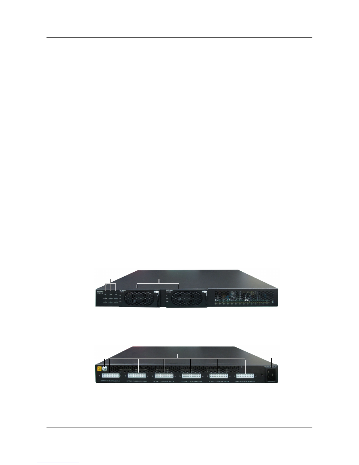
2.8.1 Functions
RPS1800 is a redundant power supply unit for a switch when the internal power supply unit of
the switch fails.
RPS1800 provides the following functions:
l Clears the power-off risk when the internal power supply unit of a switch fails.
l Provides power backup for a maximum of six network devices, and can take over power
supply for one device when its internal power supply unit fails.
l Stops power supply when the faulty internal power of the switch recovers.
l Connects to two 800 W swappable 48 V power supply units.
l Provides 800 W PoE for two switches concurrently after software configuration.
l Supports the setting of port priorities.
Applications
RPS1800 can provide power supply for S5700-28P-LI-AC, S5700-28P-LI-DC, S5700-52P-LIAC, S5700-52P-LI-DC, S5700S-28P-LI-AC, S5700S-52P-LI-AC, S5700-28P-PWR-LI-AC,
and S5700-52P-PWR-LI-AC.
2.8.2 Panel
Figure 2-12 and Figure 2-13 show the appearance of the RPS1800 power supply unit connected
to S5700.
Figure 2-12 Front view of the RPS1800 power supply unit
1
2
1. RPS power indicator
2. Two swappable power supply unit slots
Figure 2-13 Rear view of the RPS1800 power supply unit
3
4
5
3. Ground screw
4. Six DC output terminals 5. AC jack
Table 2-11 describes the meanings of RPS1800 indicators.
S5700&S5710 Series Ethernet Switches
Hardware Description 2 Power Supply Unit
Issue 01 (2012-03-15) Huawei Proprietary and Confidential
Copyright © Huawei Technologies Co., Ltd.
40
Page 49
Table 2-11 Description of RPS1800 power indicators
Name Status Description
PWR Green The input power is within
range.
Off The switch is powered off.
TEMP Green The temperature is within
range.
Red The temperature is out of
range.
Off The switch is powered off.
FAN Green The fan is running properly.
Red The fan is not running
properly.
Off The switch is powered off.
OUTPUT Green RPS1740 is in the cold
backup state.
Blinking green RPS1740 is supplying power
for the switch.
Amber RPS1740 is supplying power
for other devices.
Off The switch is powered off.
2.8.3 Technical Specifications
Table 2-12 shows the technical specifications of the RPS1800 power supply system.
Table 2-12 Technical specifications of the RPS1800 power supply system
Item
RPS1800 without
Power Module
Installed
RPS1800 with One
Power Module
Installed
RPS1800 with Two
Power Modules
Installed
Dimension
s (W x D x
H)
442.0 mm x 310.0 mm x 43.6 mm
Weight 3.3 kg (without power modules installed)
Operating
temperatur
e
0°C-45°C (at 0-4000 m altitude)
S5700&S5710 Series Ethernet Switches
Hardware Description 2 Power Supply Unit
Issue 01 (2012-03-15) Huawei Proprietary and Confidential
Copyright © Huawei Technologies Co., Ltd.
41
Page 50
Item RPS1800 without
Power Module
Installed
RPS1800 with One
Power Module
Installed
RPS1800 with Two
Power Modules
Installed
Storage
temperatur
e
-40°C-70°C
Relative
humidity
5%RH-95%RH
Rated
input
voltage
100 V-240 V AC; 50/60 Hz
Maximum
input
voltage
90 V-264 V AC; 45 Hz-65 Hz
Rated
input
current
2 A 6 A 10 A
Maximum
output
current
12 V: 11.6 A
l 12 V: 11.6 A
l -53.5 V: 15 A (input
voltage 175 V-240 V
AC)
l -53.5 V: 7.5 A (input
voltage 100 V-175 V
AC)
l 12 V: 11.6 A
l -53.5 V: 30 A (input
voltage 175 V-240 V
AC)
l -53.5 V: 15 A (input
voltage 100 V-175 V
AC)
Maximum
output
power
12 V: 140 W
l 12 V: 140 W
l -53.5 V: 800 W
(input voltage 175
V-240 V AC)
l -53.5 V: 370 W
(input voltage 100
V-175 V AC)
l 12 V: 140 W
l -53.5 V: 1600 W
(input voltage 175
V-240 V AC)
l -53.5 V: 800 W
(input voltage 100
V-175 V AC)
NOTE
On the RPS power system, each interface provides 140 W power when the voltage is 12 V and 800 W
power when the voltage is -53.5 V.
S5700&S5710 Series Ethernet Switches
Hardware Description 2 Power Supply Unit
Issue 01 (2012-03-15) Huawei Proprietary and Confidential
Copyright © Huawei Technologies Co., Ltd.
42
Page 51

3 Heat Dissipation System
About This Chapter
This chapter describes the heat dissipation system of the S5700.
3.1 Heat Dissipation Mode
This section describes the heat dissipation modes of the S5700.
3.2 Fan Module
This section describes the appearance and technical specifications of the S5700 fan module.
S5700&S5710 Series Ethernet Switches
Hardware Description 3 Heat Dissipation System
Issue 01 (2012-03-15) Huawei Proprietary and Confidential
Copyright © Huawei Technologies Co., Ltd.
43
Page 52

3.1 Heat Dissipation Mode
This section describes the heat dissipation modes of the S5700.
The heat dissipation system ensures that the S5700 operates at a normal temperature. The
operating temperature of the S5700 is the operating temperature in Physical Specifications.
The heat dissipation system can be in the following modes:
l Natural heat dissipation
l Intelligent heat dissipation
l Forcible heat dissipation
Table 3-1 provides the S5700 models corresponding to each heat dissipation mode.
Table 3-1 S5700 heat dissipation modes
Heat
Dissipati
on Mode
Model
Natural
heat
dissipation
l S5700-28P-LI-AC
l S5700-28P-LI-DC
l S5700S-28P-LI-AC
Intelligent
heat
dissipation
l S5700-24TP-SI-AC
l S5700-24TP-SI-DC
l S5700-48TP-SI-AC
l S5700-48TP-SI-DC
S5700&S5710 Series Ethernet Switches
Hardware Description 3 Heat Dissipation System
Issue 01 (2012-03-15) Huawei Proprietary and Confidential
Copyright © Huawei Technologies Co., Ltd.
44
Page 53

Heat
Dissipati
on Mode
Model
Forcible
heat
dissipation
l S5700-28C-EI
l S5700-28C-EI-24S
l S5700-52C-EI
l S5700-24TP-PWR-SI
l S5700-48TP-PWR-SI
l S5700-28C-PWR-EI
l S5700-52C-PWR-EI
l S5700-28C-SI
l S5700-52C-SI
l S5700-28C-HI
l S5700-28C-HI-24S
l S5700-6TP-LI-AC
l S5700-52P-LI-AC
l S5700-52P-LI-DC
l S5700S-52P-LI-AC
l S5710-28C-EI
l S5710-52C-EI
l S5700-28P-PWR-LI-AC
l S5700-52P-PWR-LI-AC
NOTE
The fans can work in the intelligent mode or forcible mode.
In the intelligent mode, the fans start to operate only when the ambient temperature goes higher than a
specified value.
The following table describes the air circulation through the S5700 chassis.
S5700&S5710 Series Ethernet Switches
Hardware Description 3 Heat Dissipation System
Issue 01 (2012-03-15) Huawei Proprietary and Confidential
Copyright © Huawei Technologies Co., Ltd.
45
Page 54
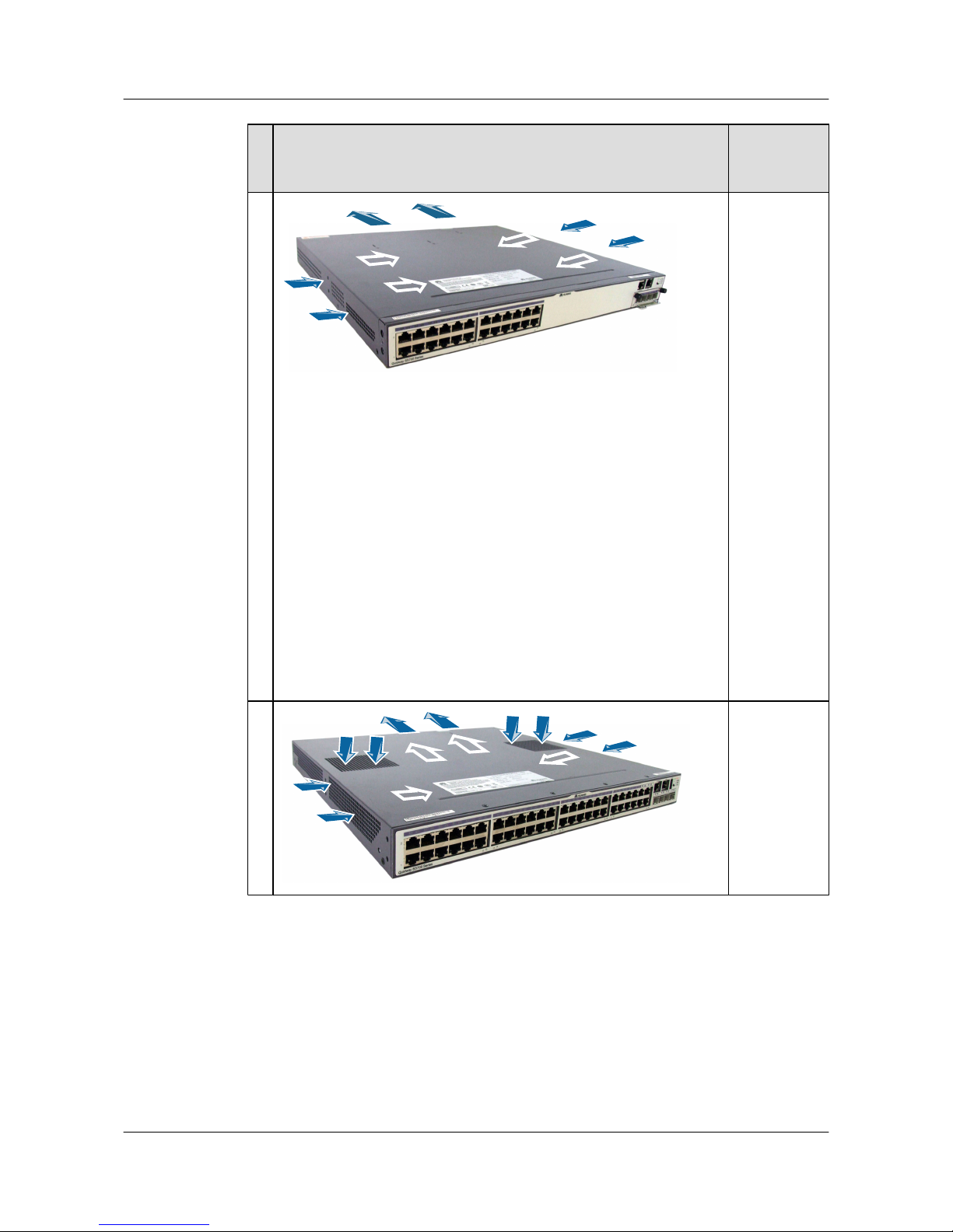
N
o
.
Air Circulation Model
1
l S5700-28
C-EI
l S5700-28
C-EI-24S
l S5700-52
C-EI
l S5700-24
TP-PWRSI
l S5700-48
TP-PWRSI
l S5700-28
C-PWREI
l S5700-52
C-PWREI
l S5700-28
C-SI
l S5700-52
C-SI
l S5700-6T
P-LI-AC
2
l S5700-24
TP-SI-AC
l S5700-24
TP-SI-DC
l S5700-48
TP-SI-AC
l S5700-48
TP-SI-DC
S5700&S5710 Series Ethernet Switches
Hardware Description 3 Heat Dissipation System
Issue 01 (2012-03-15) Huawei Proprietary and Confidential
Copyright © Huawei Technologies Co., Ltd.
46
Page 55
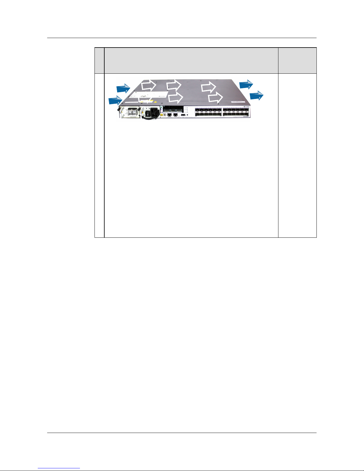
N
o
.
Air Circulation Model
3
l S5700-28
C-HI
l S5700-28
C-HI-24S
l S5700-52
P-LI-AC
l S5700-52
P-LI-DC
l S5700S-5
2P-LI-AC
l S5710-28
C-EI
l S5710-52
C-EI
l S5700-28
P-PWRLI-AC
l S5700-52
P-PWRLI-AC
3.2 Fan Module
This section describes the appearance and technical specifications of the S5700 fan module.
Appearance
The S5700 fan module consists of two fans. The fans can be replaced when the device is
operating.
The fan module can be installed on S5700-28C-EI-24S, S5700-28C-EI, S5700-28C-SI,
S5700-52C-EI, S5700-52C-SI, S5700-28C-PWR-EI, S5700-52C-PWR-EI, S5700-24TP-PWRSI, and S5700-48TP-PWR-SI.
Figure 3-1 shows the appearance of the fan module.
S5700&S5710 Series Ethernet Switches
Hardware Description 3 Heat Dissipation System
Issue 01 (2012-03-15) Huawei Proprietary and Confidential
Copyright © Huawei Technologies Co., Ltd.
47
Page 56
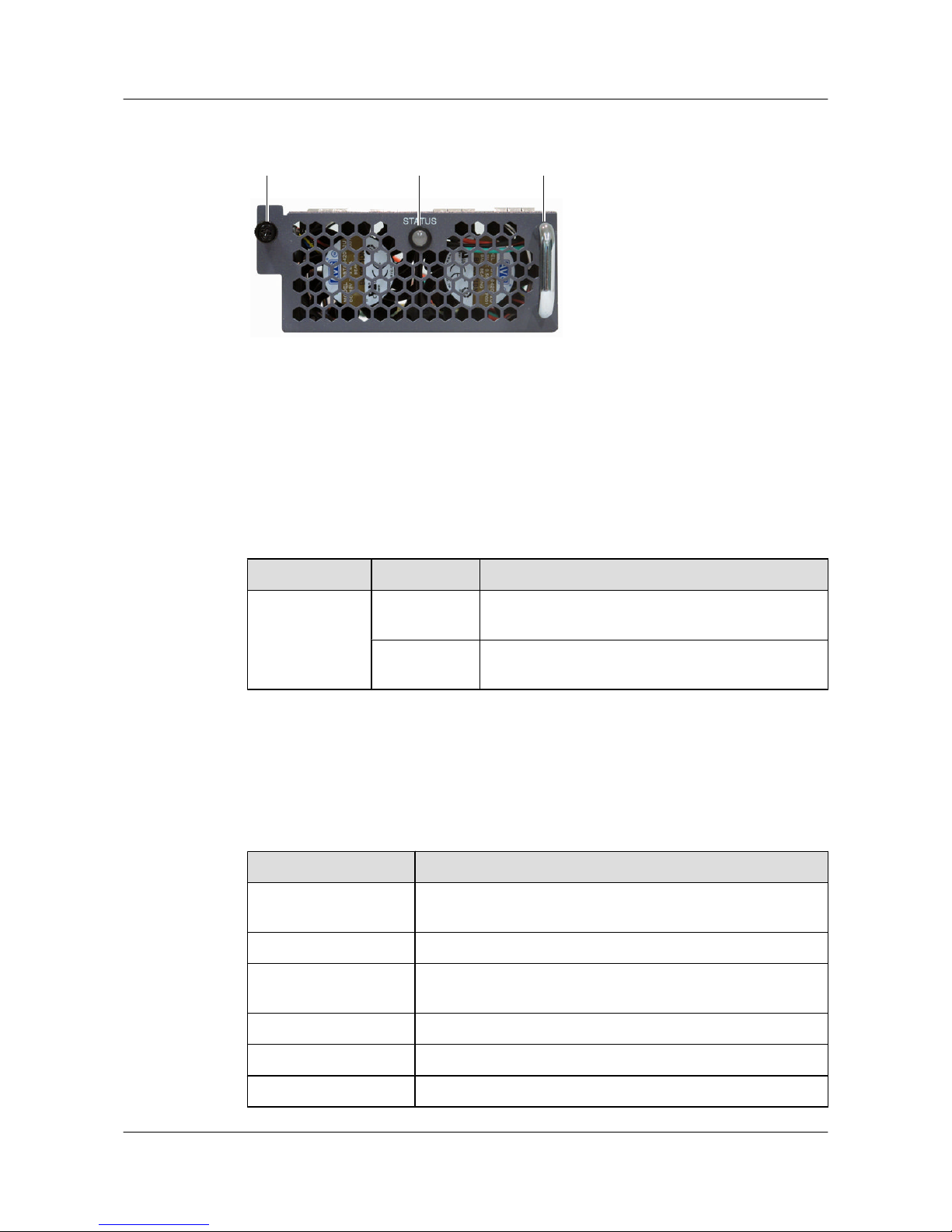
Figure 3-1 Fan module appearance
1 2 3
1. Captive screw 2. Indicator 3. Handle
Indicator
Table 3-2 describes the fan module indicator of the S5700.
Table 3-2 Fan indicator description
Name
Color Description
STATUS Blinking green
(1 Hz)
The fan module is operating properly.
Blinking red (1
Hz)
The fan module is faulty.
Technical Specifications
Table 3-3 describes the technical specifications of the S5700 fan module.
Table 3-3 Fan module technical specifications
Item
Specification
Dimensions (width x
depth x height)
103.0 mm x 99.2 mm x 39.6 mm
Weight 230 g to 270 g
Maximum power
consumption
12 W
Maximum wind pressure 375 Pa
Maximum wind rate 40 CFM
Maximum noise 60 dB
S5700&S5710 Series Ethernet Switches
Hardware Description 3 Heat Dissipation System
Issue 01 (2012-03-15) Huawei Proprietary and Confidential
Copyright © Huawei Technologies Co., Ltd.
48
Page 57

Item Specification
Operating voltage 12 V DC
S5700&S5710 Series Ethernet Switches
Hardware Description 3 Heat Dissipation System
Issue 01 (2012-03-15) Huawei Proprietary and Confidential
Copyright © Huawei Technologies Co., Ltd.
49
Page 58

4 Interface Subcards
About This Chapter
This section describes the interface subcards supported by the S5700.
4.1 Introduction
This section provides an overview of the interface subcards supported by the S5700, including
interface subcard types, relationships between interface subcards, and interface numbers.
4.2 E2XY-2-Port 10GE SFP+ Optical Interface Subcard
This section describes the functions, appearance, indicators, interfaces, and technical
specifications of the 2-port 10GE SFP+ optical interface subcard.
4.3 E4GF/E4GFA-4-Port GE Optical Interface Subcard
This section describes the functions, appearance, indicators, interfaces, and technical
specifications of the 4-port GE SFP optical interface subcard.
4.4 E4XY-4-Port 10GE SFP+ Optical Interface Subcard
This section describes the functions, appearance, indicators, interfaces, and technical
specifications of the 4-port 10GE SFP+ optical interface subcard.
4.5 X2SA/X4SA-2/4-Port GE SFP/10G SFP+ Optical Interface Subcard
This section describes the functions, appearance, indicators, interfaces, and technical
specifications of the 2/4-port GE SFP/10G SFP+ optical interface subcard.
4.6 G4SC-4-Port GE SFP Optical Interface Subcard
This section describes the functions, appearance, indicators, interfaces, and technical
specifications of the 4-port GE SFP optical interface subcard.
4.7 ES5D21G08S00-8-Port GE SFP Optical Interface Rear Subcard
This section describes the functions, appearance, indicators, interfaces, and technical
specifications of the 8-port GE SFP optical interface rear subcard.
4.8 ES5D21G08T00-8-Port GE Electronic Interface Rear Subcard
This section describes the functions, appearance, indicators, interfaces, and technical
specifications of the 8-port GE electronic interface rear subcard.
4.9 ES5D21X02S00-2-Port GE SFP/10G SFP+ Optical Interface Subcard
This section describes the functions, appearance, indicators, interfaces, and technical
specifications of the 2-port GE SFP/10G SFP+ optical interface subcard.
S5700&S5710 Series Ethernet Switches
Hardware Description 4 Interface Subcards
Issue 01 (2012-03-15) Huawei Proprietary and Confidential
Copyright © Huawei Technologies Co., Ltd.
50
Page 59

4.10 ETPC-Stack Rear Subcard
This section describes the functions, appearance, indicators, interfaces, and technical
specifications of the stack subcard.
4.11 ETPB-Extended Rear Subcard
This section describes the functions, appearance, indicators, interfaces, and technical
specifications of the extended rear subcard.
S5700&S5710 Series Ethernet Switches
Hardware Description 4 Interface Subcards
Issue 01 (2012-03-15) Huawei Proprietary and Confidential
Copyright © Huawei Technologies Co., Ltd.
51
Page 60

4.1 Introduction
This section provides an overview of the interface subcards supported by the S5700, including
interface subcard types, relationships between interface subcards, and interface numbers.
4.1.1 Interface Subcard Types
Table 4-1 lists the interface subcards supported by the S5700.
Table 4-1 List of the interface cards supported by the S5700
Interface Subcard
Type
Name Supported Device Model
Front subcard E2XY-2-port 10GE
SFP+ optical
interface subcard
l S5700-28C-EI
l S5700-52C-EI
l S5700-28C-EI-24S
l S5700-28C-SI
l S5700-52C-SI
l S5700-28C-PWR-EI
l S5700-52C-PWR-EI
E4XY-4-port 10GE
SFP+ optical
interface subcard
l S5700-28C-EI
l S5700-52C-EI
l S5700-28C-EI-24S
l S5700-28C-SI
l S5700-52C-SI
l S5700-28C-PWR-EI
l S5700-52C-PWR-EI
E4GFA-4-port GE
optical interface
subcard
S5700SI
E4GF-4-port GE
optical interface
subcard
S5700EI
X4SA-4-port GE
SFP/10G SFP+
optical interface
subcard
l S5700-28C-HI
l S5700-28C-HI-24S
X2SA-2-port GE
SFP/10G SFP+
optical interface
subcard
S5700&S5710 Series Ethernet Switches
Hardware Description 4 Interface Subcards
Issue 01 (2012-03-15) Huawei Proprietary and Confidential
Copyright © Huawei Technologies Co., Ltd.
52
Page 61
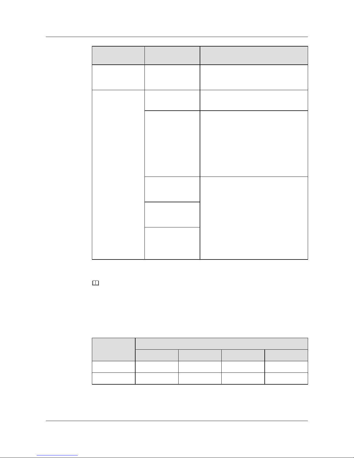
Interface Subcard
Type
Name Supported Device Model
G4SC-4-port GE SFP
optical interface
subcard
Rear subcard ETPC-stack rear
subcard
l S5700EI
l S5700SI
ETPB-extended rear
subcard
l S5700-28C-EI
l S5700-52C-EI
l S5700-28C-EI-24S
l S5700-28C-SI
l S5700-52C-SI
l S5700-28C-PWR-EI
l S5700-52C-PWR-EI
ES5D21G08S00-8port GE SFP optical
interface rear subcard
l S5710-28C-EI
l S5710-52C-EI
ES5D21G08T00-8port GE electronic
interface rear subcard
ES5D21X02S00-2port GE SFP/10G
SFP+ optical
interface subcard
NOTE
Interface subcards on the S5700C series except the S5710-28C-EI, S5710-52C-EI, S5700-28C-HI and
S5700-28C-HI-24S are not hot swappable.
An S5700C switch cannot be configured with both ETPB and ETPC. Table 4-2 lists the
restrictions on subcard selection.
Table 4-2 Subcard selection restriction
Rear Subcard
Front Subcard
E2XY E4XY E4GFA E4GF
ETPC Y Y Y Y
ETPB N Y Y Y
l Y-can be used
S5700&S5710 Series Ethernet Switches
Hardware Description 4 Interface Subcards
Issue 01 (2012-03-15) Huawei Proprietary and Confidential
Copyright © Huawei Technologies Co., Ltd.
53
Page 62
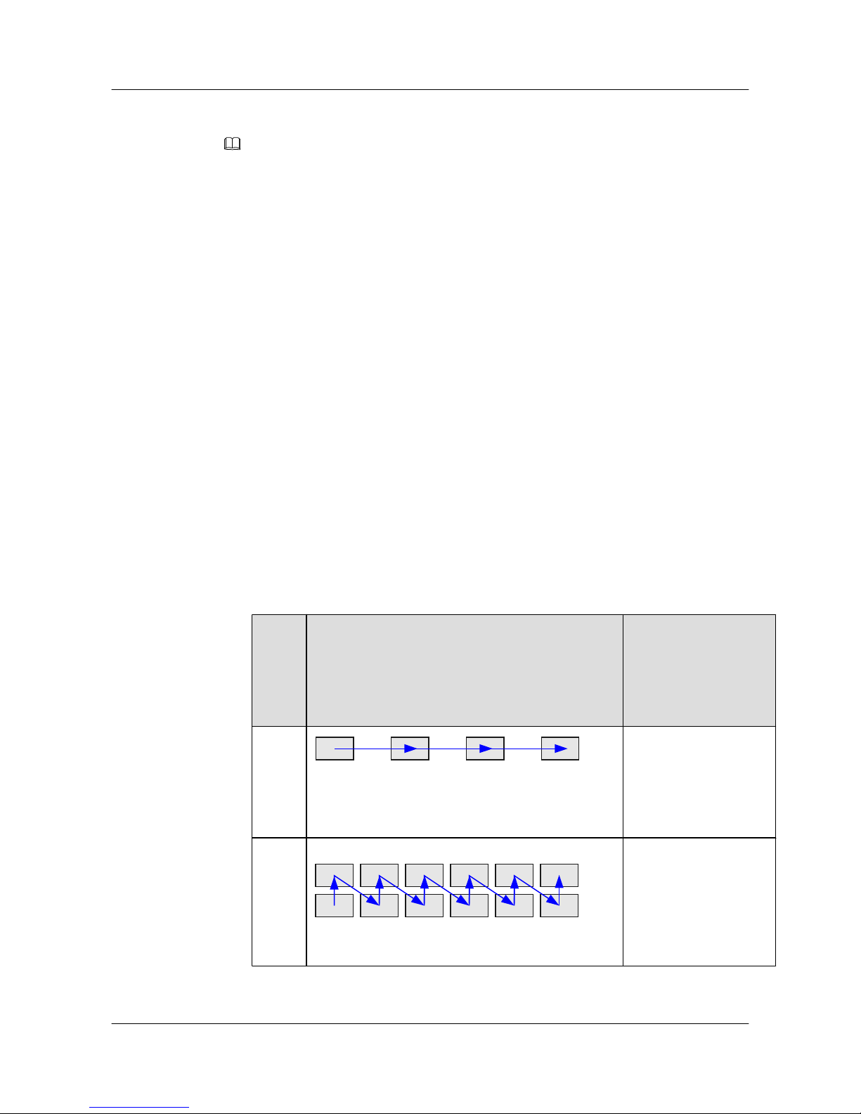
l N-not recommended
NOTE
When the S5700EI or S5700SI is equipped with ETPC:
l If the E4XY front subcard is used, only ports 1 and 3 are available.
l If the E4GFA or E4GF front subcard is used, only ports 1 and 2 are available.
4.1.2 Interface Numbering
On the S5700, interfaces are numbered in the format of slot ID/subcard ID/interface sequence
number.
l Slot ID
The slot ID specifies the ID of the slot where a card resides. The S5700 supports only one
card that integrates the control, switching, and service functions, so the slot ID is always
0.
l Subcard ID
The S5700 supports one front subcard or two rear subcards; therefore, the subcard ID can
be 0, 1, or 2.
The value 1 or 2 indicates that interfaces are on subcards. The value 0 indicates that an
interface is on the host.
l Interface sequence number
The interface sequence number indicates the number of each interface on a subcard as
shown in Table 4-3.
Table 4-3 Interface numbering rules
Num
ber of
Rows
for
Interf
aces
Diagram for Interface Numbering Description
1
1 2 3 4
There is only one row of
interfaces on the
interface subcard. These
interfaces are numbered
from left to right starting
with 1.
2
1 3 5 7 9 11
2 4 6 8 10 12
There are two rows of
interfaces on the
interface subcard. These
interfaces are numbered
from bottom to top and
left to right starting with
1.
S5700&S5710 Series Ethernet Switches
Hardware Description 4 Interface Subcards
Issue 01 (2012-03-15) Huawei Proprietary and Confidential
Copyright © Huawei Technologies Co., Ltd.
54
Page 63
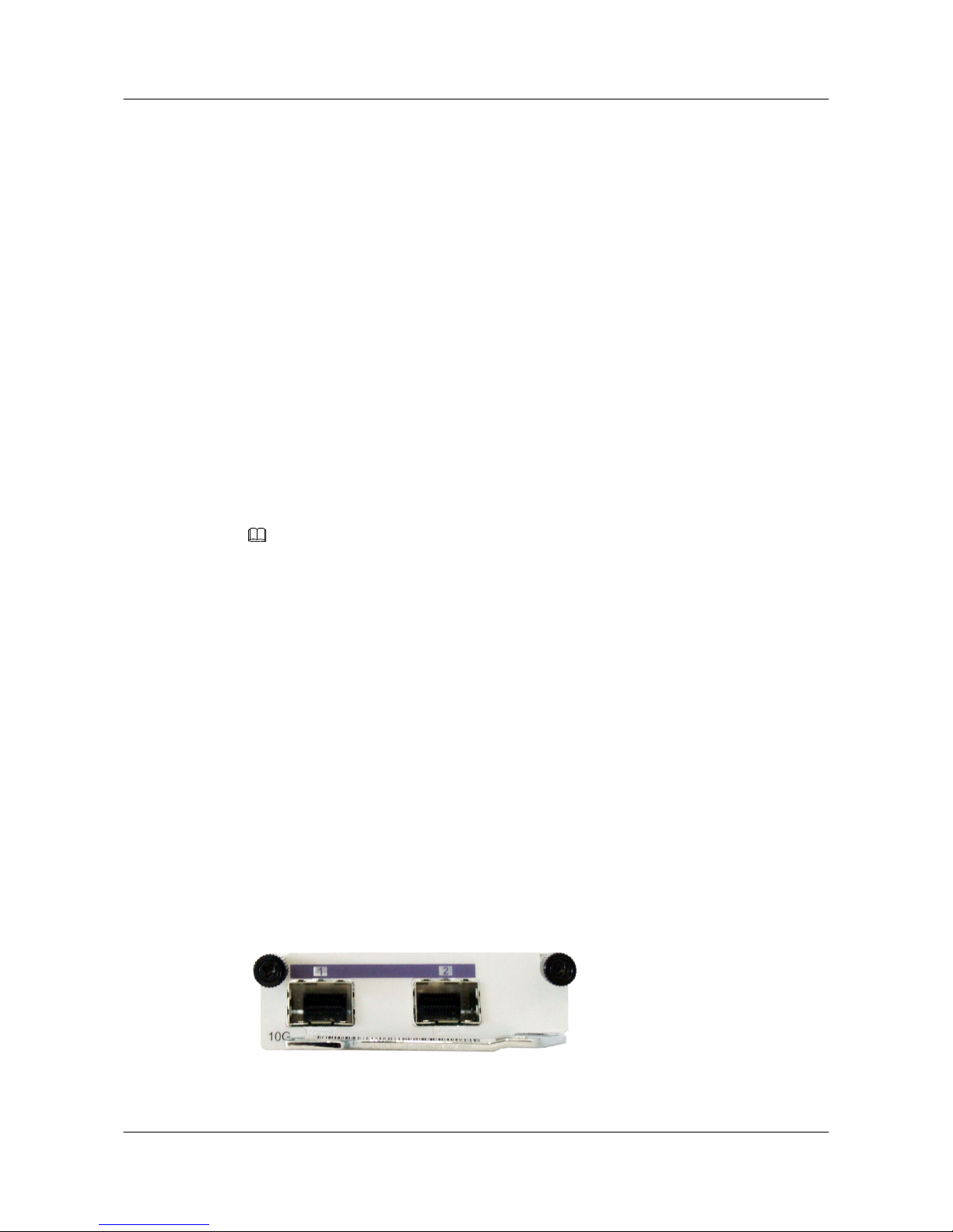
l If an interface does not reside on a front subcard and is the fifth interface from left to right
and top to bottom, the interface is named Ethernet 0/0/5. If the stacking function is enabled
and the stack ID is 1, the interface is named Ethernet 1/0/5.
l If an interface resides on a front subcard and is the third interface from left to right, the
interface is named Ethernet 0/1/3. If the stacking function is enabled and the stack ID is 1,
the interface is named Ethernet 1/1/3.
4.2 E2XY-2-Port 10GE SFP+ Optical Interface Subcard
This section describes the functions, appearance, indicators, interfaces, and technical
specifications of the 2-port 10GE SFP+ optical interface subcard.
4.2.1 Functions and Applications
Functions
The E2XY provides two 10GE SFP+ optical interfaces to implement data access and line-speed
switching.
NOTE
The two optical interfaces of the E2XY support only the 10G SFP+ optical modules.
The cost of a 10GE interface is higher than that of other interfaces, so it is used as an uplink
aggregation interface on high-bandwidth and high-speed Metropolitan Area Networks (MANs)
or backbone networks. When an enterprise user needs the high-quality triple-play service, the
E2XY provides access interfaces for downlink devices or networks. The E2XY uses fibers as
transmission media and supports up to 40 km transmission distance. Different transmission
distances can be supported by changing SFP+ optical modules.
Applications
The E2XY can be inserted into the front subcard slot of the S5700-28C-EI, S5700-52C-EI,
S5700-28C-EI-24S, S5700-28C-SI, S5700-52C-SI, S5700-28C-PWR-EI, or S5700-52C-PWREI.
4.2.2 Panel
Figure 4-1 shows the appearance of the E2XY.
Figure 4-1 Appearance of the E2XY
S5700&S5710 Series Ethernet Switches
Hardware Description 4 Interface Subcards
Issue 01 (2012-03-15) Huawei Proprietary and Confidential
Copyright © Huawei Technologies Co., Ltd.
55
Page 64
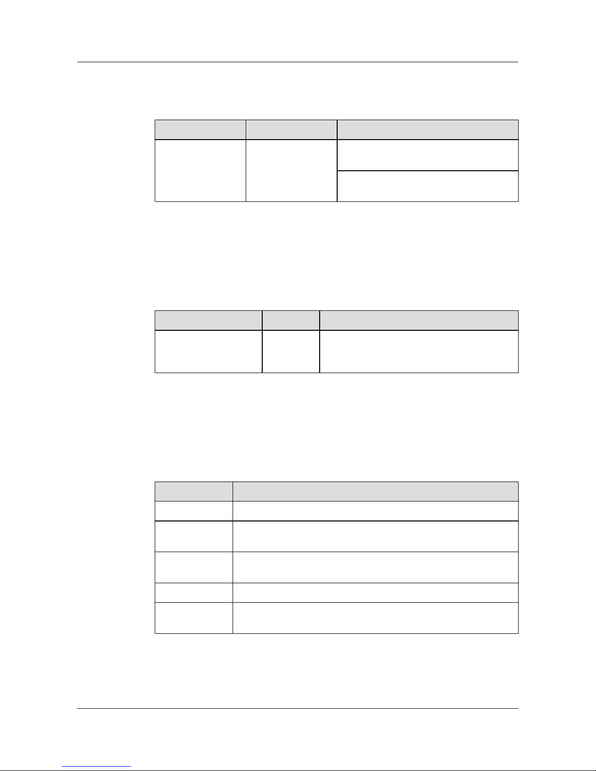
Table 4-4 describes the meanings of indicators on the E2XY.
Table 4-4 Description of indicators on the E2XY
Indicator Color Description
ACT/LINK Green-yellow If the indicator is blinking, data is being
transmitted or received.
If the indicator is steady on, a link has been
connected.
4.2.3 Interfaces
Table 4-5 describes the types and functions of interfaces on the E2XY.
Table 4-5 Types and functions of interfaces on the E2XY
Type Quantity Description
10G BASE-ER/SR/LR/
LRM optical interface
2 The E2XY provides two 10 Gbit/s optical
interfaces to transmit and receive Ethernet
services at 10 Gbit/s.
4.2.4 Interface Attributes
Table 4-6 describes the attributes of 10GE optical interfaces.
Table 4-6 Attributes of 10GE optical interfaces (10G Base-X)
Attribute
Description
Connector type LC/PC
Optical interface
attribute
Depending on the SFP+ optical module (for details, see section 7.5 SFP
+ Optical Module (10GE) Attributes)
Standards
compliance
IEEE 802.3ae
Frame format Ethernet_II, Ethernet_SAP, or Ethernet_SNAP
Network layer
protocol
IP
4.2.5 Technical Specifications
S5700&S5710 Series Ethernet Switches
Hardware Description 4 Interface Subcards
Issue 01 (2012-03-15) Huawei Proprietary and Confidential
Copyright © Huawei Technologies Co., Ltd.
56
Page 65
Table 4-7 describes the technical specifications of the E2XY.
Table 4-7 Technical specifications of the E2XY
Parameter Description
Dimensions (depth
x width x height)
200.0 mm x 69.0 mm x 22.0 mm
Power
consumption
6.5 W
Weight 0.2 kg
4.3 E4GF/E4GFA-4-Port GE Optical Interface Subcard
This section describes the functions, appearance, indicators, interfaces, and technical
specifications of the 4-port GE SFP optical interface subcard.
4.3.1 Functions and Applications
Functions
The E4GF/E4GFA provides four GE SFP optical interfaces to implement data access and linespeed switching.
The E4GF or E4GFA is not hot swappable.
The cost of a GE interface is higher than that of other interfaces, so it is used as an uplink
aggregation interface on high-bandwidth and high-speed Metropolitan Area Networks (MANs)
or backbone networks. When an enterprise user needs the high-quality triple-play service, the
E4GF/E4GFA provides access interfaces for downlink devices or networks. The E4GF/E4GFA
uses fibers as transmission media and supports up to 100 km transmission distance. Different
transmission distances can be supported by changing ESFP optical modules.
Applications
CAUTION
The E4GF cannot work on the S5700SI and the E4GFA cannot work on the S5700EI.
The E4GF/E4GFA front subcard should be used together with the ETPB extended rear subcard;
otherwise, only two interfaces of the front subcard can work.
The E4GF can be inserted into the front subcard slot of the S5700-28C-EI, S5700-52C-EI,
S5700-28C-EI-24S, S5700-28C-PWR-EI, or S5700-52C-PWR-EI.
The E4GFA can be inserted into the front subcard slot of the S5700-28C-SI, or S5700-52C-SI.
S5700&S5710 Series Ethernet Switches
Hardware Description 4 Interface Subcards
Issue 01 (2012-03-15) Huawei Proprietary and Confidential
Copyright © Huawei Technologies Co., Ltd.
57
Page 66
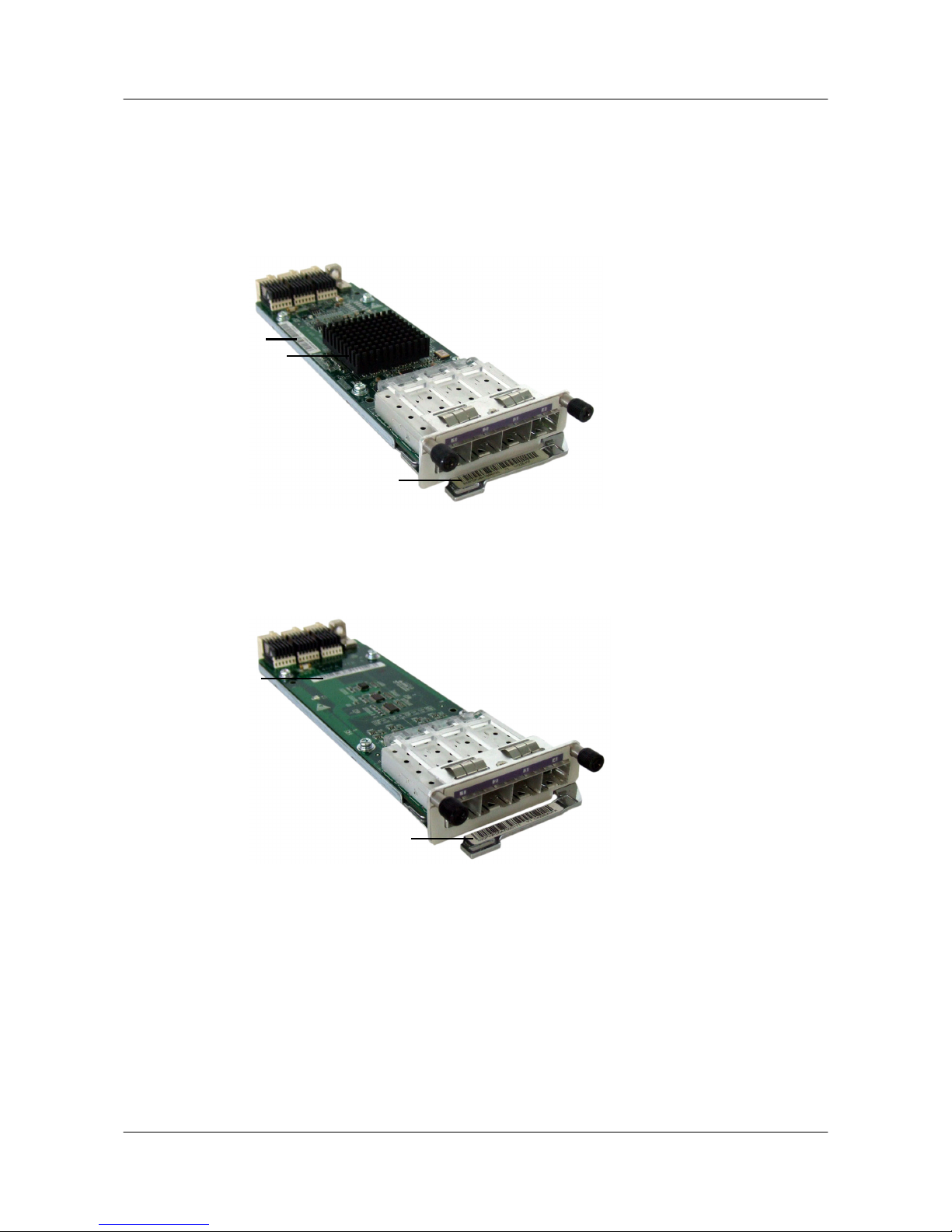
4.3.2 Panel
Figure 4-2 shows the appearance of the E4GF (applicable to the S5700EI).
Figure 4-2 Appearance of the E4GF
3
2
1
Figure 4-3 shows the appearance of the E4GFA (applicable to the S5700SI).
Figure 4-3 Appearance of the E4GFA
1
2
1. Front panel label
2. Silkscreen and card label 3. Cooling fin
Differences between the E4GF and E4GFA are as follows:
l The labels on the front panels are different. The front panel label of the E4GF is CX22E4GF,
and the front panel label of the E4GFA is CX22E4GFA.
l The silkscreens and bar codes on the front cards are different, as shown in Figure 4-2 and
Figure 4-3. The silkscreens show the card types and versions. The silkscreen of the E4GF
is CX22E4GF VER.A, and the silkscreen of the E4GFA is CX22E4GFA VER.A. The card
labels show the card types. The label of the E4GF is CX22E4GF, and the label of the E4GFA
is CX22E4GFA.
S5700&S5710 Series Ethernet Switches
Hardware Description 4 Interface Subcards
Issue 01 (2012-03-15) Huawei Proprietary and Confidential
Copyright © Huawei Technologies Co., Ltd.
58
Page 67

l The card appearances are different. The E4GF has the cooling fins, as shown in Figure
4-2, whereas the E4GFA does not, as shown in Figure 4-3.
Table 4-8 describes the meanings of indicators on the E4GF/E4GFA.
Table 4-8 Description of indicators on the E4GF/E4GFA
Indicator Color Description
ACT/LINK Green-yellow If the indicator is blinking, data is being
transmitted or received.
If the indicator is steady on, a link has been
connected.
4.3.3 Interfaces
Table 4-9 describes the types and functions of interfaces on the E4GF/E4GFA.
Table 4-9 Types and functions of interfaces on the E4GF/E4GFA
Type
Quantity Description
1000M BASE-X optical
interface
4 The E4GF or E4GFA provides four 1000 Mbit/s
optical interfaces to transmit and receive Ethernet
services at 1000 Mbit/s.
4.3.4 Interface Attributes
Table 4-10 describes the optical interface attributes.
Table 4-10 Attributes of GE optical interfaces (1000M Base-X)
Attribute
Description
Connector type LC/PC
Optical interface
attribute
Depending on the optical module (for details, see section 7.3 ESFP
Optical Module (GE) Attributes and section 7.4 ESFP CWDM-SFP
Optical Module)
Standards
compliance
IEEE 802.3Z
Frame format Ethernet_II, Ethernet_SAP, or Ethernet_SNAP
Network layer
protocol
IP
S5700&S5710 Series Ethernet Switches
Hardware Description 4 Interface Subcards
Issue 01 (2012-03-15) Huawei Proprietary and Confidential
Copyright © Huawei Technologies Co., Ltd.
59
Page 68

4.3.5 Technical Specifications
Table 4-11 describes the technical specifications of the E4GF/E4GFA.
Table 4-11 Technical specifications of the E4GF/E4GFA
Parameter Description
Dimensions (depth
x width x height)
200.0 mm x 69.0 mm x 22.0 mm
Power
consumption
6 W for the E4GF
4.5 W for the E4GFA
Weight 0.2 kg
4.4 E4XY-4-Port 10GE SFP+ Optical Interface Subcard
This section describes the functions, appearance, indicators, interfaces, and technical
specifications of the 4-port 10GE SFP+ optical interface subcard.
4.4.1 Functions and Applications
Functions
The E4XY provides four 10GE SFP+ optical interfaces to implement data access and line-speed
switching.
NOTE
The four optical interfaces provided by the E4XY support only the 10G SFP+ optical modules.
Applications
The E4XY can be inserted into the front subcard slot of the S5700-28C-SI, S5700-52C-SI,
S5700-28C-EI, S5700-52C-EI, S5700-28C-PWR-EI, S5700-52C-PWR-EI or S5700-28CEI-24S.
The E4XY is not hot swappable.
The cost of a 10GE interface is higher than that of other interfaces, so it is used as an uplink
aggregation interface on high-bandwidth and high-speed Metropolitan Area Networks (MANs)
or backbone networks. When an enterprise user needs the high-quality triple-play service, the
E4XY provides access interfaces for downlink devices or networks. The E4XY uses fibers as
transmission media and supports up to 40 km transmission distance. Different transmission
distances can be supported by changing SFP+ optical modules.
S5700&S5710 Series Ethernet Switches
Hardware Description 4 Interface Subcards
Issue 01 (2012-03-15) Huawei Proprietary and Confidential
Copyright © Huawei Technologies Co., Ltd.
60
Page 69
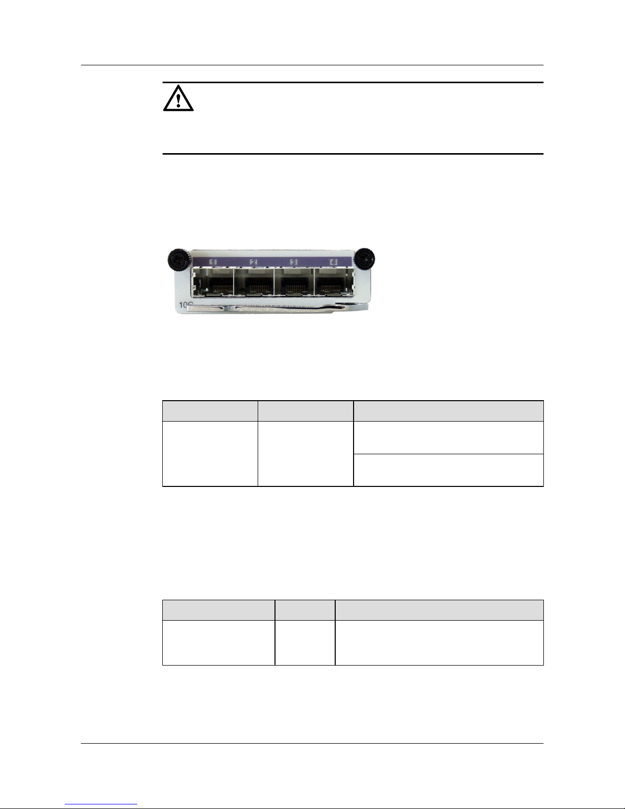
CAUTION
The E4XY front subcard should be used together with the ETPB extended rear subcard;
otherwise, only two interfaces of the front subcard can work.
4.4.2 Panel
Figure 4-4 shows the appearance of the E4XY.
Figure 4-4 Appearance of the E4XY
Table 4-12 describes the meanings of indicators on the E4XY.
Table 4-12 Description of indicators on the E4XY
Indicator
Color Description
ACT/LINK Green-yellow If the indicator is blinking, data is being
transmitted or received.
If the indicator is steady on, a link has been
connected.
4.4.3 Interfaces
Table 4-13 describes the types and functions of interfaces on the E4XY.
Table 4-13 Types and functions of interfaces on the E4XY
Type
Quantity Description
10G BASE-ER/SR/LR/
LRM optical interface
4 The E4XY provides four 10 Gbit/s optical
interfaces to transmit and receive Ethernet
services at 10 Gbit/s.
4.4.4 Interface Attributes
S5700&S5710 Series Ethernet Switches
Hardware Description 4 Interface Subcards
Issue 01 (2012-03-15) Huawei Proprietary and Confidential
Copyright © Huawei Technologies Co., Ltd.
61
Page 70
Table 4-14 describes the attributes of 10GE optical interfaces.
Table 4-14 Attributes of 10GE optical interfaces (10G Base-X)
Attribute Description
Connector type LC/PC
Optical interface
attribute
Depending on the SFP+ optical module (for details, see section 7.5 SFP
+ Optical Module (10GE) Attributes)
Standards
compliance
IEEE 802.3ae
Frame format Ethernet_II, Ethernet_SAP, or Ethernet_SNAP
Network layer
protocol
IP
4.4.5 Technical Specifications
Table 4-15 describes the technical specifications of the E4XY.
Table 4-15 Technical specifications of the E4XY
Parameter
Description
Dimensions (depth
x width x height)
200.0 mm x 69.0 mm x 22.0 mm
Power
consumption
13 W
Weight 0.3 kg
4.5 X2SA/X4SA-2/4-Port GE SFP/10G SFP+ Optical Interface
Subcard
This section describes the functions, appearance, indicators, interfaces, and technical
specifications of the 2/4-port GE SFP/10G SFP+ optical interface subcard.
4.5.1 Functions and Applications
Functions
The X2SA/X4SA provides two/four 10G SFP+ optical interfaces to implement data access and
line-speed switching.
S5700&S5710 Series Ethernet Switches
Hardware Description 4 Interface Subcards
Issue 01 (2012-03-15) Huawei Proprietary and Confidential
Copyright © Huawei Technologies Co., Ltd.
62
Page 71
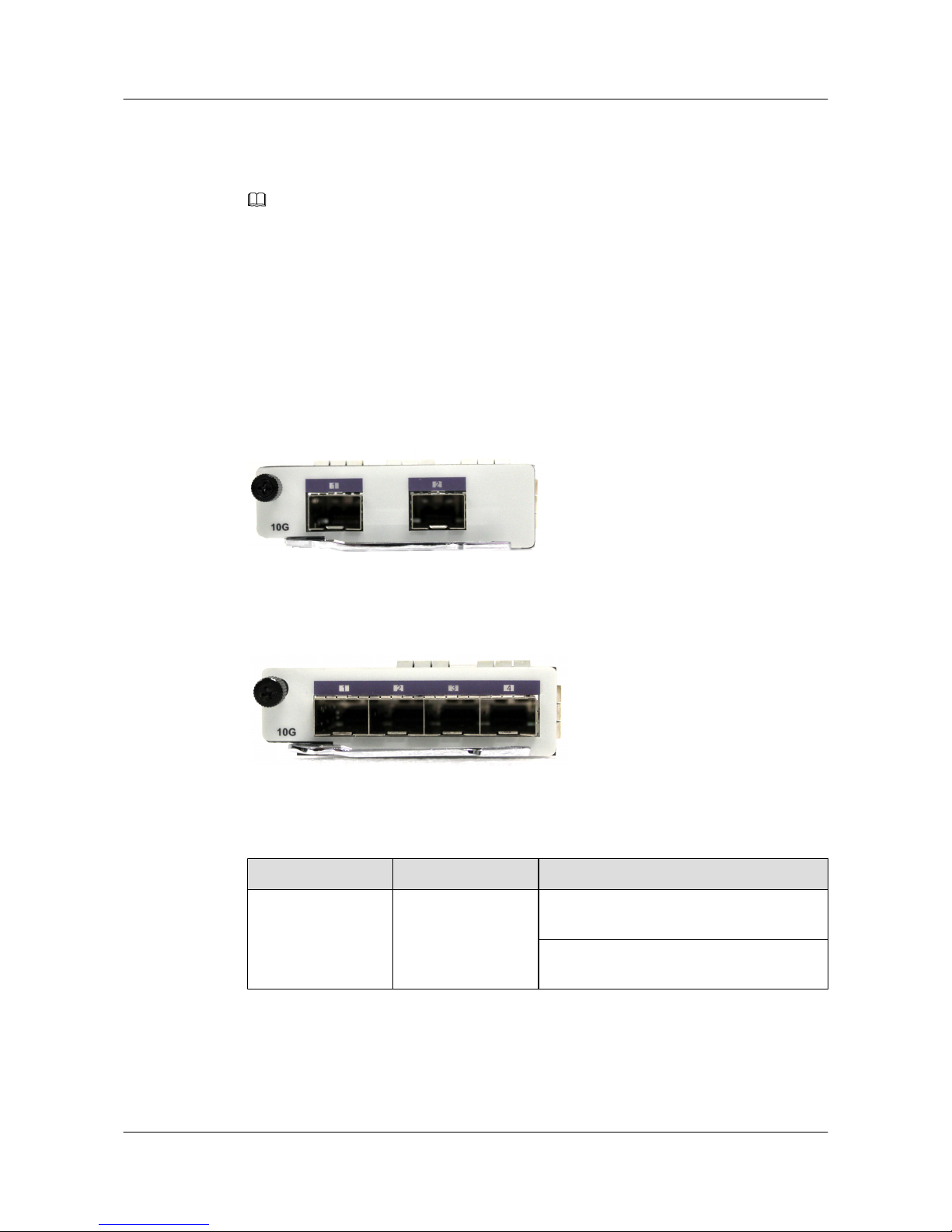
The S5700HI SCU powers on or off the X2SA/X4SA, and detects whether the X2SA/X4SA is
installed or not, and manages PHY chips and optical interfaces on the X2SA/X4SA. The X2SA/
X4SA works with the entire system to provide enhanced service features such as OAM and BFD.
NOTE
The X2SA/X4SA provides two/four optical interfaces, which can be connected to 10G SFP+ and 1000M
SFP optical modules.
Applications
The X2SA/X4SA can be inserted into the front subcard slot of the S5700HI and is hot swappable.
4.5.2 Panel
Figure 4-5 shows the appearance of the X2SA.
Figure 4-5 Appearance of the X2SA
Figure 4-6 shows the appearance of the X4SA.
Figure 4-6 Appearance of the X4SA
Table 4-16 describes the meanings of indicators on the X2SA/X4SA.
Table 4-16 Description of indicators on the X2SA/X4SA
Indicator
Color Description
ACT/LINK Green-yellow If the indicator is blinking, data is being
transmitted or received.
If the indicator is steady on, a link has been
connected.
4.5.3 Interfaces
Table 4-17 describes the types and functions of interfaces on the X2SA/X4SA.
S5700&S5710 Series Ethernet Switches
Hardware Description 4 Interface Subcards
Issue 01 (2012-03-15) Huawei Proprietary and Confidential
Copyright © Huawei Technologies Co., Ltd.
63
Page 72
Table 4-17 Types and functions of interfaces on the X2SA/X4SA
Type Quantity Description
10G BASE-SR/LR/
LRM/ER optical
interface (X2SA)
2 The X2SA provides two 10 Gbit/s optical
interfaces to transmit and receive Ethernet
services at 10 Gbit/s.
10G BASE-SR/LR/
LRM/ER optical
interface (X4SA)
4 The X4SA provides four 10 Gbit/s optical
interfaces to transmit and receive Ethernet
services at 10 Gbit/s.
NOTE
The X2SA/X4SA provides two/four optical interfaces, which can be connected to 10G SFP+ or 1000M
SFP optical modules.
4.5.4 Interface Attributes
Table 4-18 describes the attributes of optical interfaces on the X2SA/X4SA.
Table 4-18 Attributes of interfaces on the X2SA/X4SA
Attribute
Description
Connector type LC/PC
Optical interface
attribute
Depending on the optical module (for details, see section 7.5 SFP+
Optical Module (10GE) Attributes and section 7.3 ESFP Optical
Module (GE) Attributes)
Standards
compliance
IEEE 802.3ae
Frame format Ethernet_II, Ethernet_SAP, or Ethernet_SNAP
Network layer
protocol
IP
4.5.5 Technical Specifications
Table 4-19 describes the technical specifications of the X2SA/X4SA.
Table 4-19 Technical specifications of the X2SA/X4SA
Parameter
Description
Dimensions (depth
x width x height)
200.0 mm x 77.0 mm x 23.0 mm
S5700&S5710 Series Ethernet Switches
Hardware Description 4 Interface Subcards
Issue 01 (2012-03-15) Huawei Proprietary and Confidential
Copyright © Huawei Technologies Co., Ltd.
64
Page 73
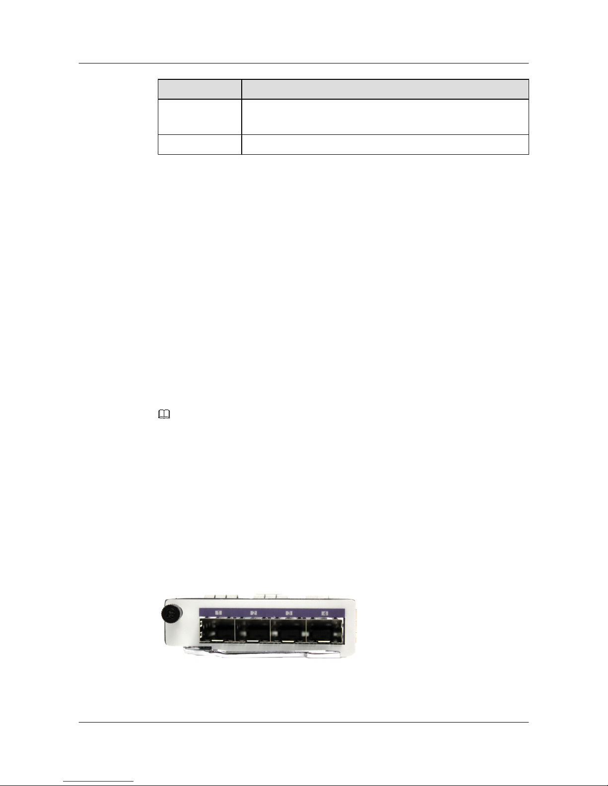
Parameter Description
Power
consumption
7 W for the X2SA
10 W for the X4SA
Weight 0.5 kg
4.6 G4SC-4-Port GE SFP Optical Interface Subcard
This section describes the functions, appearance, indicators, interfaces, and technical
specifications of the 4-port GE SFP optical interface subcard.
4.6.1 Functions and Applications
Functions
The G4SC provides four 1000M SFP optical interfaces to implement data access and line-speed
switching.
The S5700HI SCU powers on or off the G4SC, detects whether the G4SC is installed or not,
and optical interfaces on the G4SC. The G4SC works with the entire system to provide enhanced
service features such as OAM and BFD.
NOTE
G4SC supports the optical/electrical module (shielded network cables are required). For details, see 7.6
Optical/Electrical Module (GE) Attributes.
Applications
The G4SC can be inserted into the front subcard slot of the S5700HI and is hot swappable.
4.6.2 Panel
Figure 4-7 shows the appearance of the G4SC.
Figure 4-7 Appearance of the G4SC
Table 4-20 describes the meanings of indicators on the G4SC.
S5700&S5710 Series Ethernet Switches
Hardware Description 4 Interface Subcards
Issue 01 (2012-03-15) Huawei Proprietary and Confidential
Copyright © Huawei Technologies Co., Ltd.
65
Page 74

Table 4-20 Description of indicators on the G4SC
Indicator Color Description
ACT/LINK Green-yellow If the indicator is blinking, data is being
transmitted or received.
If the indicator is steady on, a link has been
connected.
4.6.3 Interfaces
Table 4-21 describes the types and functions of interfaces on the G4SC.
Table 4-21 Types and functions of interfaces on the G4SC
Type Quantity Description
1000M BASE-X optical
interface
4 The G4SC provides four 1000 Mbit/s optical
interfaces to transmit and receive services at 1000
Mbit/s.
4.6.4 Interface Attributes
Table 4-22 describes the optical interface attributes.
Table 4-22 Attributes of GE optical interfaces (1000M Base-X)
Attribute
Description
Connector type LC/PC
Optical interface
attribute
Depending on the optical module (for details, see section 7.3 ESFP
Optical Module (GE) Attributes and section 7.4 ESFP CWDM-SFP
Optical Module)
Standards
compliance
IEEE 802.3Z
Frame format Ethernet_II, Ethernet_SAP, or Ethernet_SNAP
Network layer
protocol
IP
4.6.5 Technical Specifications
Table 4-23 lists the technical specifications of the G4SC.
S5700&S5710 Series Ethernet Switches
Hardware Description 4 Interface Subcards
Issue 01 (2012-03-15) Huawei Proprietary and Confidential
Copyright © Huawei Technologies Co., Ltd.
66
Page 75
Table 4-23 Technical specifications of the G4SC
Parameter Description
Dimensions (depth
x width x height)
200.0 mm x 77.0 mm x 23.0 mm
Power
consumption
4 W
Weight 0.3 kg
4.7 ES5D21G08S00-8-Port GE SFP Optical Interface Rear
Subcard
This section describes the functions, appearance, indicators, interfaces, and technical
specifications of the 8-port GE SFP optical interface rear subcard.
4.7.1 Functions and Applications
Functions
ES5D21G08S00 provides eight 1000 Mbit/s SFP optical interfaces to implement data access
and line-speed switching.
NOTE
The eight optical interfaces on ES5D21G08S00 only support GE SFP optical modules.
Applications
ES5D21G08S00 can be installed in the rear subcard slot on S5710-52C-EI and S5710-28C-EI.
ES5D21G08S00 supports hot swap.
4.7.2 Panel
Figure 4-8 shows the ES5D21G08S00 appearance.
S5700&S5710 Series Ethernet Switches
Hardware Description 4 Interface Subcards
Issue 01 (2012-03-15) Huawei Proprietary and Confidential
Copyright © Huawei Technologies Co., Ltd.
67
Page 76
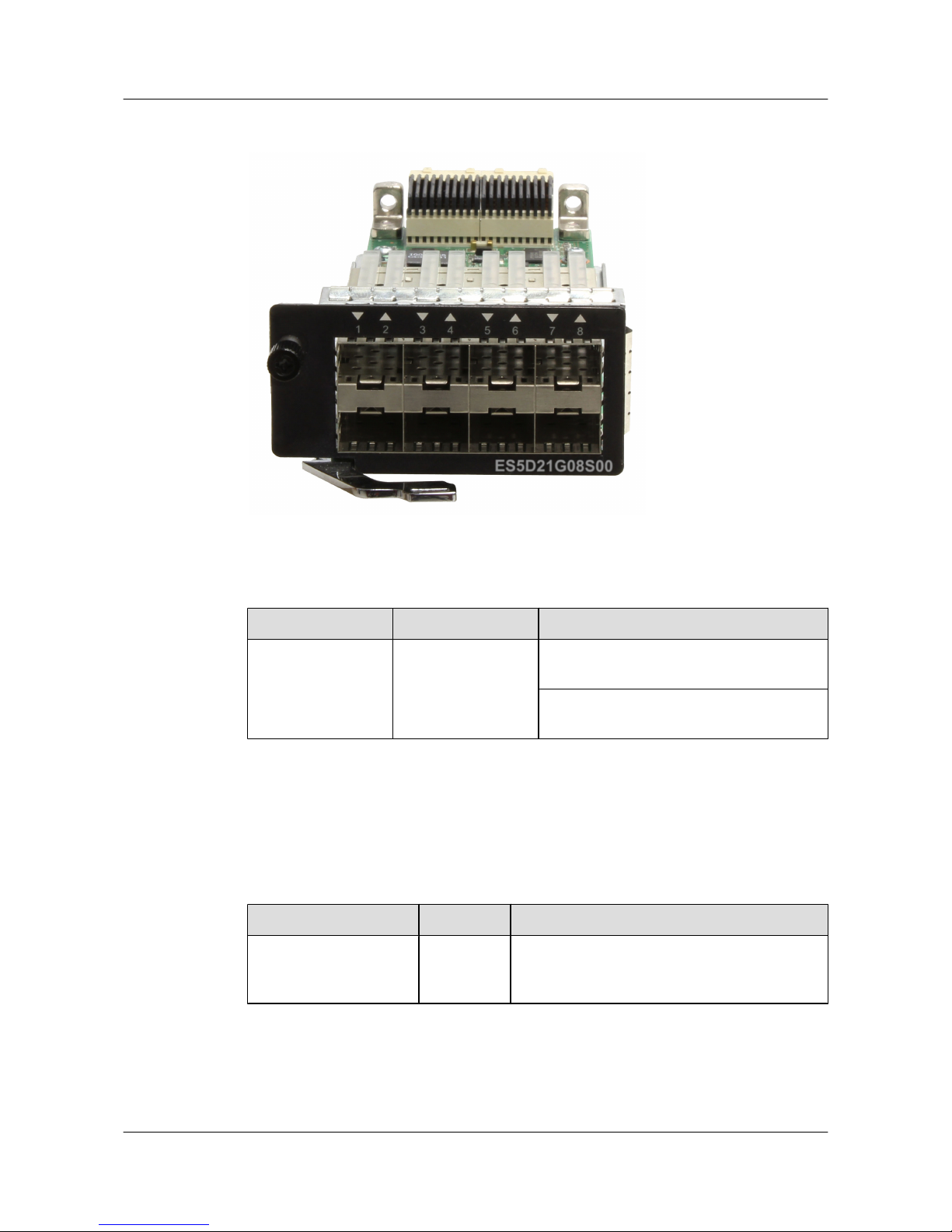
Figure 4-8 ES5D21G08S00 appearance
Table 4-24 describes the meanings of indicators on the ES5D21G08S00.
Table 4-24 Description of ES5D21G08S00 indicators
Indicator
Color Description
ACT/LINK Green If the indicator is blinking, data is being
transmitted or received.
If the indicator is steady on, a link has been
connected.
4.7.3 Interfaces
Table 4-25 describes the types and functions of interfaces on the ES5D21G08S00.
Table 4-25 Types and functions of interfaces on the ES5D21G08S00
Interface
Quantity Description
1000 Mbit/s BASE-SX/
LX optical interface
8 ES5D21G08S00 provides eight 1000 Mbit/s
optical interfaces to transmit and receive Ethernet
services at 1000 Mbit/s.
4.7.4 Interface Attributes
S5700&S5710 Series Ethernet Switches
Hardware Description 4 Interface Subcards
Issue 01 (2012-03-15) Huawei Proprietary and Confidential
Copyright © Huawei Technologies Co., Ltd.
68
Page 77
Table 4-26 describes the optical interface attributes.
Table 4-26 Attributes of GE optical interfaces (1000M Base-SX/LX)
Attribute Description
Connector LC/PC
Optical interface
attribute
Attributes depend on the optical module. For details, see 7.3 ESFP
Optical Module (GE) Attributes and 7.4 ESFP CWDM-SFP Optical
Module.
Standards
compliance
IEEE 802.3z
Frame format Ethernet_II, Ethernet_SAP, and Ethernet_SNAP
Network protocol IP
4.7.5 Technical Specifications
Table 4-27 describes the technical specifications of the ES5D21G08S00.
Table 4-27 Technical specifications of the ES5D21G08S00
Parameter
Description
Dimensions (D x
W x H)
209.4 mm x 62.5 mm x 43.6 mm
Power
consumption
10.9 W
Weight 0.3 kg
4.8 ES5D21G08T00-8-Port GE Electronic Interface Rear
Subcard
This section describes the functions, appearance, indicators, interfaces, and technical
specifications of the 8-port GE electronic interface rear subcard.
4.8.1 Functions and Applications
Functions
ES5D21G08T00 provides eight 10/100/1000M electronic interfaces to implement data access
and line-speed switching.
S5700&S5710 Series Ethernet Switches
Hardware Description 4 Interface Subcards
Issue 01 (2012-03-15) Huawei Proprietary and Confidential
Copyright © Huawei Technologies Co., Ltd.
69
Page 78
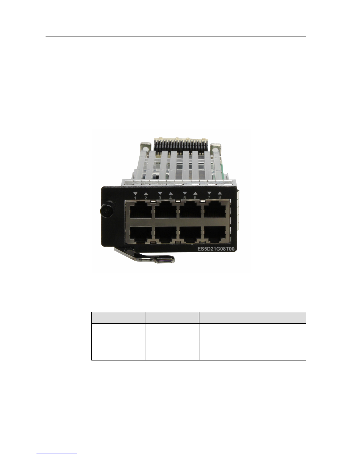
Applications
ES5D21G08T00 can be installed in the rear subcard slot on S5710-52C-EI and S5710-28C-EI.
ES5D21G08T00 supports hot swap.
4.8.2 Panel
Figure 4-9 shows the ES5D21G08T00 appearance.
Figure 4-9 ES5D21G08T00 appearance
Table 4-28 describes the meanings of indicators on the ES5D21G08T00.
Table 4-28 Description of ES5D21G08T00 indicators
Indicator
Color Description
ACT/LINK Green If the indicator is blinking, data is being
transmitted or received.
If the indicator is steady on, a link has been
connected.
4.8.3 Interfaces
Table 4-29 describes the types and functions of interfaces on the ES5D21G08T00.
S5700&S5710 Series Ethernet Switches
Hardware Description 4 Interface Subcards
Issue 01 (2012-03-15) Huawei Proprietary and Confidential
Copyright © Huawei Technologies Co., Ltd.
70
Page 79

Table 4-29 Types and functions of interfaces on the ES5D21G08T00
Interface Quantity Description
10/100/1000M BASE-T
electrical interface
8 ES5D21G08T00 provides eight 10/100/1000M
Ethernet electrical interfaces to transmit and
receive Ethernet services.
4.8.4 Interface Attributes
Table 4-30 describes the electronic interface attributes.
Table 4-30 Attributes of the 10/100/1000M Base-T Ethernet electrical interface
Attribute Description
Connector RJ45
Standards
compliance
IEEE 802.3z
Frame format Ethernet_II, Ethernet_SAP, and Ethernet_SNAP
Network protocol IP
4.8.5 Technical Specifications
Table 4-31 describes the technical specifications of the ES5D21G08T00.
Table 4-31 ES5D21G08T00 technical specifications
Parameter
Description
Dimensions (H x
W x D)
209.4 mm x 62.5 mm x 43.6 mm
Power
consumption
10.9 W
Weight 0.3 kg
4.9 ES5D21X02S00-2-Port GE SFP/10G SFP+ Optical
Interface Subcard
This section describes the functions, appearance, indicators, interfaces, and technical
specifications of the 2-port GE SFP/10G SFP+ optical interface subcard.
S5700&S5710 Series Ethernet Switches
Hardware Description 4 Interface Subcards
Issue 01 (2012-03-15) Huawei Proprietary and Confidential
Copyright © Huawei Technologies Co., Ltd.
71
Page 80

4.9.1 Functions and Applications
Functions
ES5D21X02S00 provides two 10 Gbit/s SFP+ optical interfaces to implement data access and
line-speed switching.
NOTE
The ES5D21X02S00 provides two optical interfaces, which can be connected to 10 Gbit/s SFP+ optical
modules, 1000 Mbit/s SFP+ optical modules, and stack cables.
Applications
ES5D21X02S00 can be installed in the rear subcard slot on S5710-28C-EI and S5710-52C-EI.
ES5D21X02S00 supports hot swap.
4.9.2 Panel
Figure 4-10 shows the ES5D21X02S00 appearance.
Figure 4-10 ES5D21X02S00 appearance
Table 4-32 describes the meanings of indicators on ES5D21X02S00.
Table 4-32 Description of ES5D21X02S00 indicators
Indicator
Color Description
ACT/LINK Green-yellow If the indicator is blinking, data is being
transmitted or received.
If the indicator is steady on, a link has been
connected.
4.9.3 Interfaces
S5700&S5710 Series Ethernet Switches
Hardware Description 4 Interface Subcards
Issue 01 (2012-03-15) Huawei Proprietary and Confidential
Copyright © Huawei Technologies Co., Ltd.
72
Page 81
Table 4-33 describes the types and functions of interfaces on the ES5D21X02S00.
Table 4-33 Types and functions of interfaces on the ES5D21X02S00
Interface Quantity Description
10 Gbit/s BASE-SR/LR/
LRM/ER optical
interface
2 The ES5D21X02S00 provides two 10 Gbit/s
optical interfaces to transmit and receive Ethernet
services at 10 Gbit/s.
4.9.4 Interface Attributes
Table 4-34 describes the optical interface attributes of the ES5D21X02S00.
Table 4-34 ES5D21X02S00 interface attributes
Attribute Description
Connector LC/PC
Optical interface
attribute
Attributes depend on the optical module. For details, see 7.5 SFP+
Optical Module (10GE) Attributes and 7.3 ESFP Optical Module
(GE) Attributes.
Standards
compliance
IEEE 802.3ae
Frame format Ethernet_II, Ethernet_SAP, and Ethernet_SNAP
Network protocol IP
4.9.5 Technical Specifications
Table 4-35 describes the technical specifications of the ES5D21X02S00.
Table 4-35 ES5D21X02S00 technical specifications
Parameter
Description
Dimensions (D x
W x H)
200.0 mm x 77.0 mm x 23.0 mm
Power
consumption
7 W
Weight 0.5 kg
S5700&S5710 Series Ethernet Switches
Hardware Description 4 Interface Subcards
Issue 01 (2012-03-15) Huawei Proprietary and Confidential
Copyright © Huawei Technologies Co., Ltd.
73
Page 82

4.10 ETPC-Stack Rear Subcard
This section describes the functions, appearance, indicators, interfaces, and technical
specifications of the stack subcard.
4.10.1 Functions and Applications
Functions
The ETPC provides two 12 Gbit/s electrical interfaces to implement data access and line-speed
switching.
Multiple switches can be connected using ETPC cards to function as a logical device (stack). A
maximum of nine S5700 switches are supported in a stack system.
Applications
The ETPC can be installed on the S5700-24TP-SI-AC, S5700-24TP-SI-DC, S5700-48TP-SIAC, S5700-48TP-SI-DC, S5700-28C-EI, S5700-52C-EI, S5700-28C-EI-24S, S5700-28C-SI,
S5700-52C-SI, S5700-24TP-PWR-SI, S5700-48TP-PWR-SI, S5700-28C-PWR-EI, or
S5700-52C-PWR-EI for stacking.
CAUTION
The following requirements must be met to implement stacking:
l All the member switches belong to the same series. The EI series and SI series cannot form
a stack.
l All the member switches are connected using stack cables and stack modules.
NOTE
When the S5700EI or S5700SI is equipped with ETPC:
l If the E4XY front subcard is used, only ports 1 and 3 are available.
l If the E4GFA or E4GF front subcard is used, only ports 1 and 2 are available.
4.10.2 Appearance
Figure 4-11 shows the appearance of the ETPC.
Figure 4-11 Appearance of the ETPC
S5700&S5710 Series Ethernet Switches
Hardware Description 4 Interface Subcards
Issue 01 (2012-03-15) Huawei Proprietary and Confidential
Copyright © Huawei Technologies Co., Ltd.
74
Page 83
4.10.3 Interfaces
Table 4-36 describes the types and functions of interfaces on the ETPC.
Table 4-36 Types and functions of interfaces on the ETPC
Type Quantity Description
PCI-E electrical interface 2 The ETPC provides two 12 Gbit/s electrical
interfaces to transmit and receive services, and
provides a maximum of 48 Gbit/s bidirectional
stack bandwidth.
4.10.4 Technical Specifications
Table 4-37 describes the technical specifications of the ETPC.
Table 4-37 Technical specifications of the ETPC
Parameter
Description
Dimensions (depth
x width x height)
200.0 mm x 69.0 mm x 22.0 mm
Power
consumption
0.5 W
Weight 0.2 kg
4.11 ETPB-Extended Rear Subcard
This section describes the functions, appearance, indicators, interfaces, and technical
specifications of the extended rear subcard.
4.11.1 Functions and Applications
Functions
The ETPB extended rear subcard must be used together with the E4GF/E4GFA or E4XY front
subcard to provide four SFP GE interfaces or SFP+ 10GE interfaces.
S5700&S5710 Series Ethernet Switches
Hardware Description 4 Interface Subcards
Issue 01 (2012-03-15) Huawei Proprietary and Confidential
Copyright © Huawei Technologies Co., Ltd.
75
Page 84
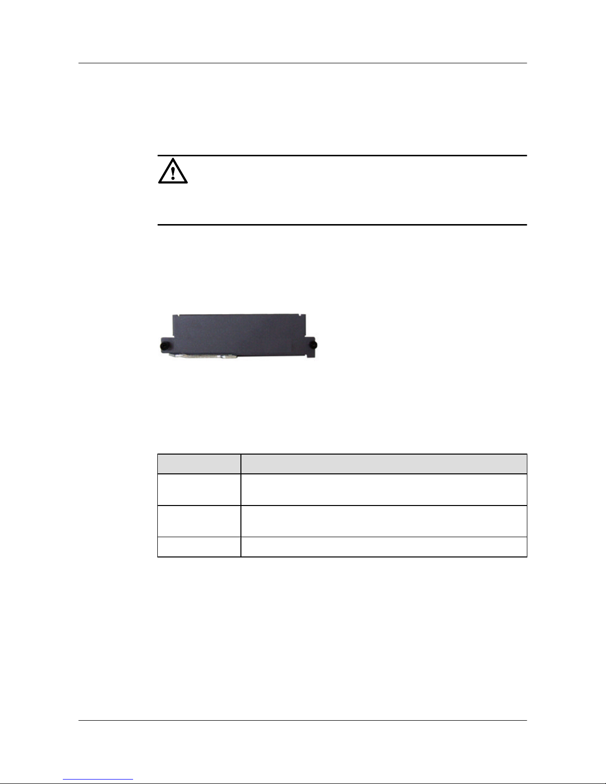
Applications
The ETPB can be inserted into the S5700-28C-EI, S5700-52C-EI, S5700-28C-EI-24S,
S5700-28C-SI, S5700-52C-SI, S5700-28C-PWR-EI, or S5700-52C-PWR-EI for interface
extension.
CAUTION
The E4GF/E4GFA or E4XY front subcard should be used together with the ETPB extended rear
subcard; otherwise, only two interfaces of the front subcard can work.
4.11.2 Appearance
Figure 4-12 shows the appearance of the ETPB.
Figure 4-12 Appearance of the ETPB
4.11.3 Technical Specifications
Table 4-38 describes the technical specifications of the ETPB.
Table 4-38 Technical specifications of the ETPB
Parameter
Description
Dimensions (depth
x width x height)
200.0 mm x 69.0 mm x 22.0 mm
Power
consumption
0.1 W
Weight 0.2 kg
S5700&S5710 Series Ethernet Switches
Hardware Description 4 Interface Subcards
Issue 01 (2012-03-15) Huawei Proprietary and Confidential
Copyright © Huawei Technologies Co., Ltd.
76
Page 85

5 Cables
About This Chapter
5.1 DC Power Cables
A DC power cable transmits DC power to the switch.
5.2 AC Power Cables
An AC power cable transmits AC power to the switch.
5.3 RPS Cable
This section describes the function, appearance, and technical specifications of remote power
supply (RPS) cables.
5.4 Ground Cables
A ground cable protects the device from lightning strike and electromagnetic interference.
5.5 Console Cables
A console cable is used to debug or maintain a local S5700.
5.6 Network Cables
A network cable subtends devices, enables a device to communication with other network
devices, and allows users to locally or remotely maintain the device.
5.7 Optical Fibers
An optical fiber connects the optical interface of a device to an upstream device or optical
network terminal.
5.8 Stack cables
This section describes the structure and technical specifications of a stack cable.
S5700&S5710 Series Ethernet Switches
Hardware Description 5 Cables
Issue 01 (2012-03-15) Huawei Proprietary and Confidential
Copyright © Huawei Technologies Co., Ltd.
77
Page 86
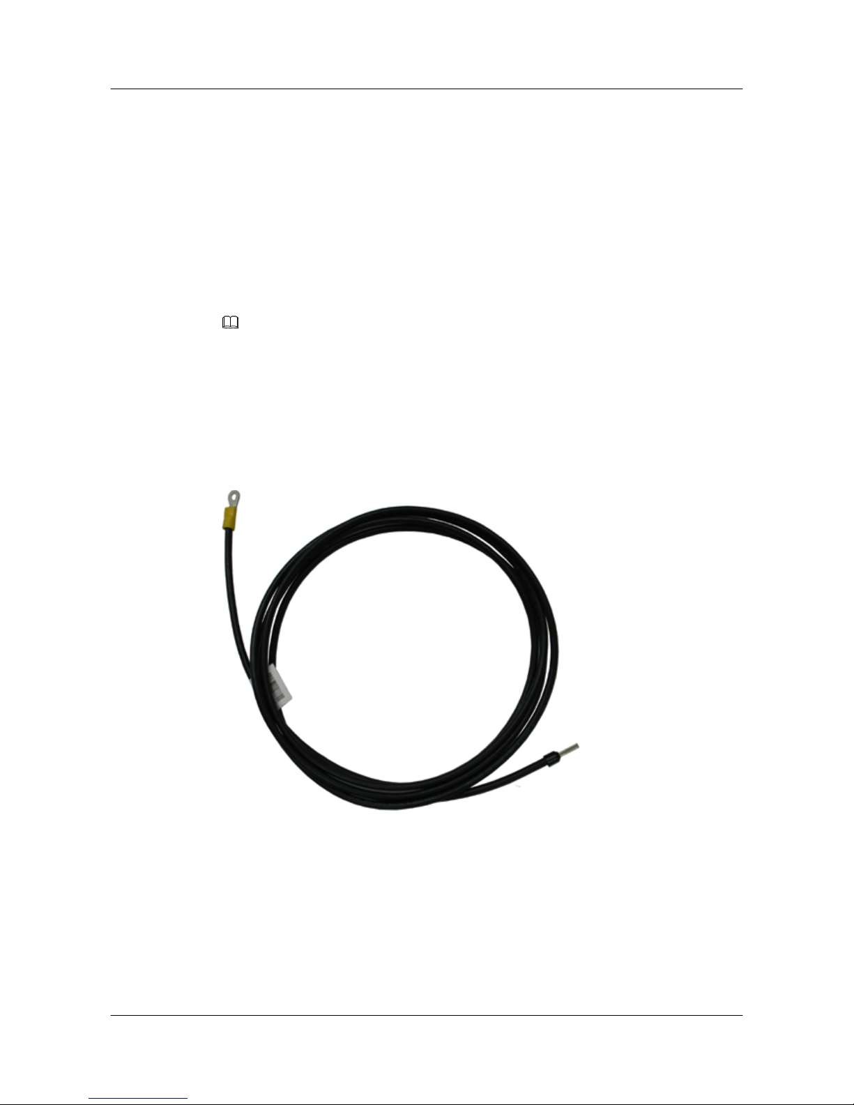
5.1 DC Power Cables
A DC power cable transmits DC power to the switch.
Applications
A DC power cable connects the following two interfaces:
l Input power jack on the chassis
l Output power interface on an external power system
NOTE
A black -48 V DC power return wire (RTN) is connected to the RTN(+) end of the DC power supply. A
blue -48 V DC power cable is connected to the NEG(-) end of the DC power supply.
Appearance and Structure
The black -48 V DC power return wire and the blue -48 V DC power cable are shown in Figure
5-1 and Figure 5-2.
Figure 5-1 -48 V DC power return wire
S5700&S5710 Series Ethernet Switches
Hardware Description 5 Cables
Issue 01 (2012-03-15) Huawei Proprietary and Confidential
Copyright © Huawei Technologies Co., Ltd.
78
Page 87
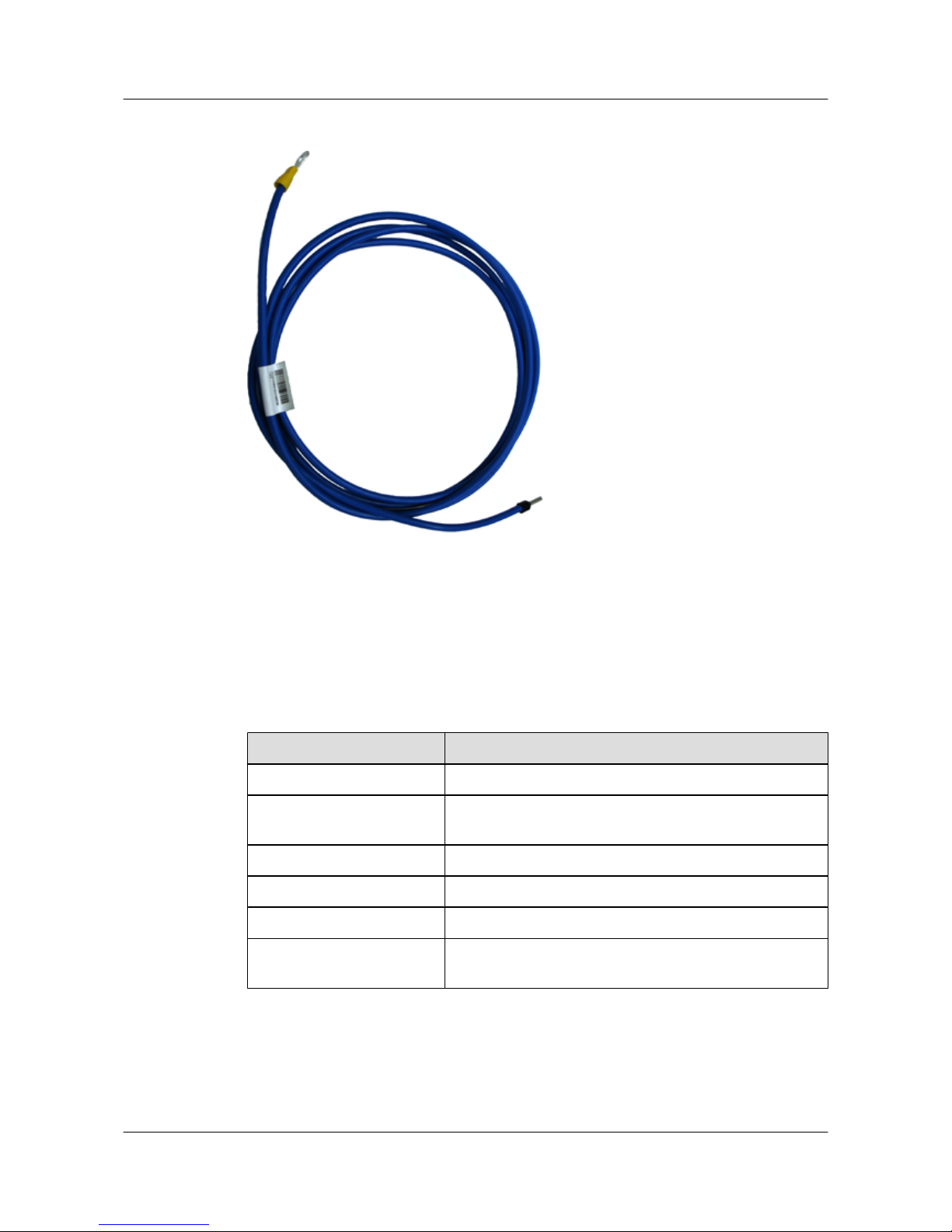
Figure 5-2 -48 V DC power cable
Specifications
The technical specifications of a -48 V DC power return wire and a -48 V DC power cable are
the same, as described in Table 5-1.
Table 5-1 Specifications of the DC power cables
Item
Description
Cable type Power cable
Color Blue for -48 V DC power cable and black for -48 V DC power
return wire
Connector 1 OT
Connector 2 Cord end terminal
Impedance 4.95 Ω/km
Conductor cross-sectional
area
1.2 mm
2
5.2 AC Power Cables
An AC power cable transmits AC power to the switch.
S5700&S5710 Series Ethernet Switches
Hardware Description 5 Cables
Issue 01 (2012-03-15) Huawei Proprietary and Confidential
Copyright © Huawei Technologies Co., Ltd.
79
Page 88
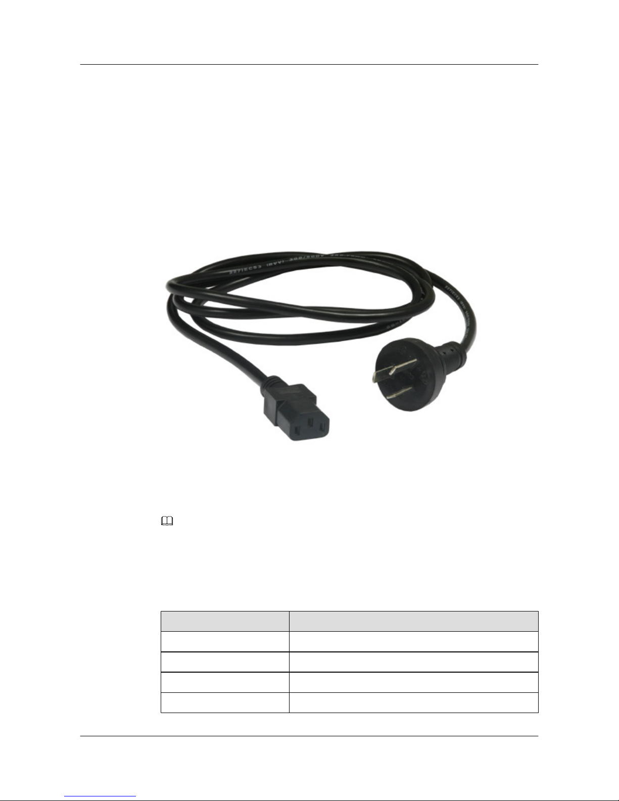
Applications
An AC power cable connects the following:
l AC input power jack on the chassis
l Mains supply
Appearance
Figure 5-3 shows the appearance of an AC power cable.
Figure 5-3 Appearance of an AC power cable
Specifications
NOTE
The AC power cables used in different countries and regions may have different specifications. The
following are the specifications of the international standard AC power cable.
Table 5-2 lists the specifications of an AC power cable.
Table 5-2 Specifications of an AC power cable
Item
Description
Cable type External power cable
Function 250 V AC/10 A complying with international standard
Connector 1 PI-straight-male
Connector 2 C13-straight-female
S5700&S5710 Series Ethernet Switches
Hardware Description 5 Cables
Issue 01 (2012-03-15) Huawei Proprietary and Confidential
Copyright © Huawei Technologies Co., Ltd.
80
Page 89
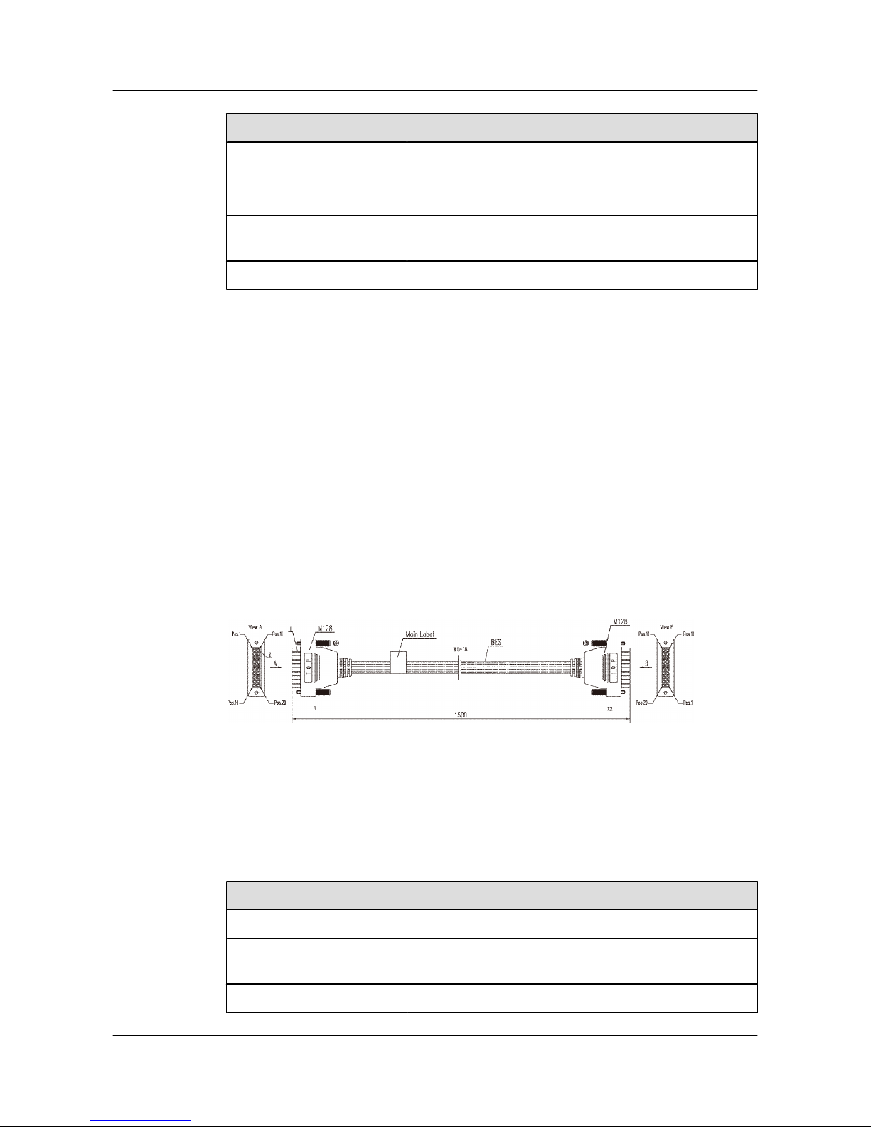
Item Description
Cable type
l 227 IEC 53 (RVV)-300 V/500 V
l Rated voltage: 300 V/500 V
l Standards compliance: 227 IEC 53 (RVV)
Conductor cross-sectional
area
3 x 1.0 mm
2
Fireproof level GB18380.1
5.3 RPS Cable
This section describes the function, appearance, and technical specifications of remote power
supply (RPS) cables.
Introduction
An RPS cable connects an RPS1800 power supply system to a switch so that the RPS1800
provides power supply to the switch.
Appearance
Figure 5-4 shows the appearance of an RPS cable.
Figure 5-4 RPS cable
Technical Specifications
Table 5-3 shows the technical specifications of the RPS cable.
Table 5-3 RPS cable technical specifications
Item
Description
Type Power cable
Description Power cable-1.5m-(H20(4.2))-(17*18UL3385 black
+CC2P0.48 black(S)-I)-(H20(4.2))-LSZH
Applicable environment Indoors
S5700&S5710 Series Ethernet Switches
Hardware Description 5 Cables
Issue 01 (2012-03-15) Huawei Proprietary and Confidential
Copyright © Huawei Technologies Co., Ltd.
81
Page 90
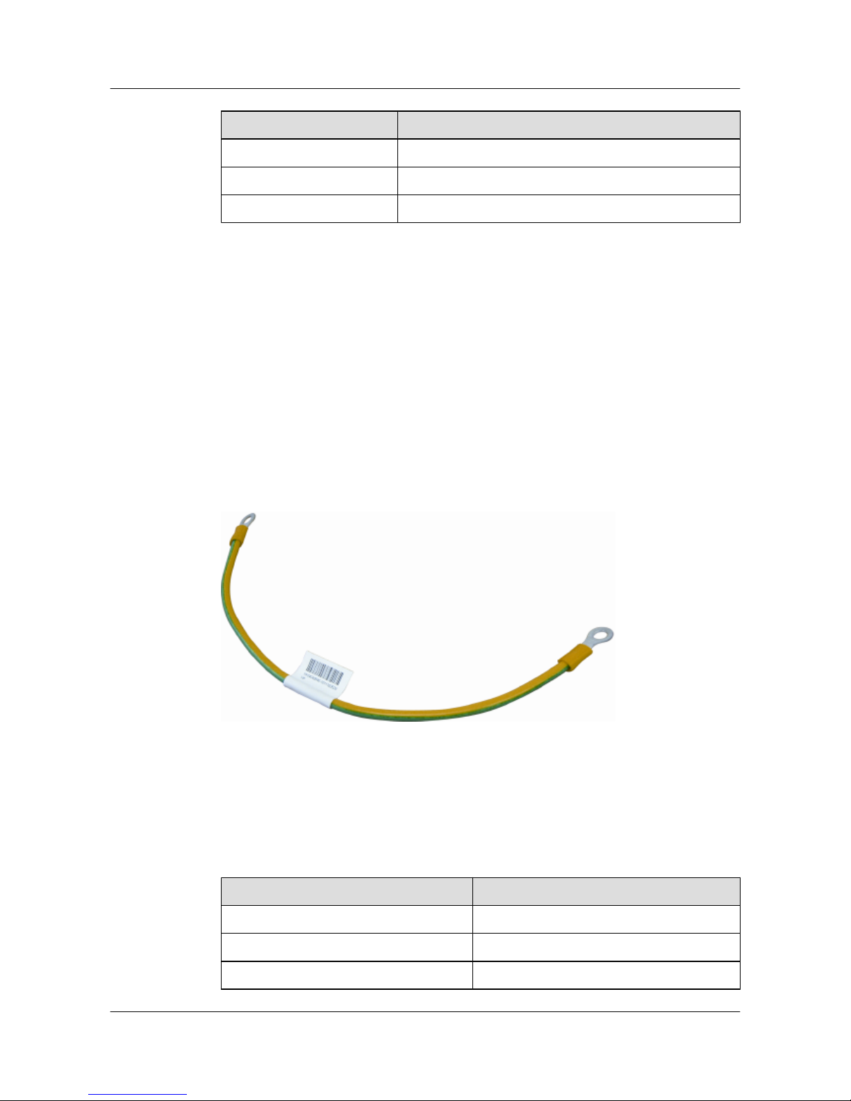
Item Description
Length 1.5 m
Name RPS cable
Weight 0.15 kg
5.4 Ground Cables
A ground cable protects the device from lightning strike and electromagnetic interference.
Applications
A ground cable connects the chassis to the ground.
Appearance
Figure 5-5 shows the appearance of a ground cable.
Figure 5-5 Appearance of a ground cable
Specifications
Table 5-4 lists the specifications of a ground cable.
Table 5-4 Specifications of a ground cable
Item
Description
Cable type Power cable
Color Green-yellow
Connector type (X1/X2) OT/OT naked crimping terminal
S5700&S5710 Series Ethernet Switches
Hardware Description 5 Cables
Issue 01 (2012-03-15) Huawei Proprietary and Confidential
Copyright © Huawei Technologies Co., Ltd.
82
Page 91
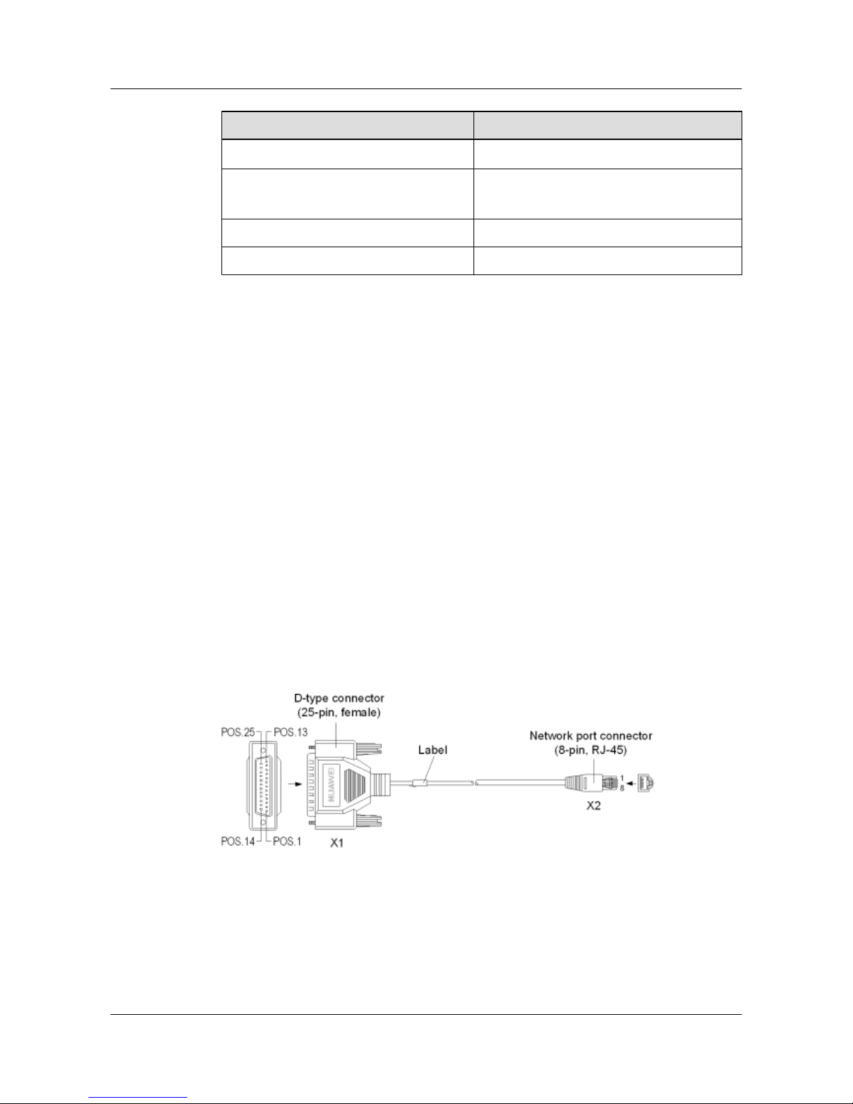
Item Description
Gauge
10 AWG (cross-sectional area ≈ 6 mm2)
Cable type
l Standards compliance: UL1015
l Length: 0.4 m
Maximum current 50 A
Fireproof level VW-1, CSA FT1
5.5 Console Cables
A console cable is used to debug or maintain a local S5700.
Applications
A console cable connects the console port of the S5700 to the serial port of an operation terminal
to transmit configuration data. A shielded cable or an unshielded cable can be used according
to the onsite situation.
A console cable connects the S5700 and terminal as follows:
l The 8-pin RJ45 connector is inserted into the S5700 console port.
l The DB9 connector is inserted into the terminal serial port.
Appearance and Structure
Figure 5-6 shows the structure of a console cable.
Figure 5-6 Structure of a console cable
Pin Assignments
Table 5-5 describes the pin assignments of a console cable.
S5700&S5710 Series Ethernet Switches
Hardware Description 5 Cables
Issue 01 (2012-03-15) Huawei Proprietary and Confidential
Copyright © Huawei Technologies Co., Ltd.
83
Page 92
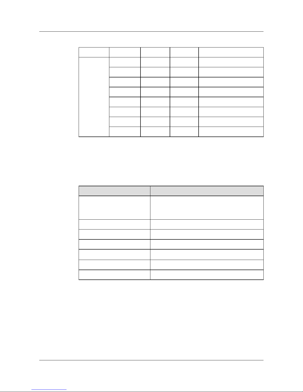
Table 5-5 Pin assignments of a console cable
Connector X2 (RJ45) Direction X1 (DB9) Signal
Pin
assignment
1 ---> 8 Clear to Send (CTS)
2 ---> 6 Data Set Ready (DSR)
3 ---> 2 Receive Data (RXD)
4 --- 5 GND
5 --- 5 GND
6 <--- 3 Transmit Data (TXD)
7 <--- 4 Data Terminal Ready (DTR)
8 <--- 7 Request to Send (RTS)
Specifications
Table 5-6 lists the specifications of a console cable.
Table 5-6 Specifications of a console cable
Item
Description
Connector type
l Connector X1: cable connector, D-type, 9-pin, male
l Connector X2: network interface connector, RJ45, 8-
pin, 8-bit
Cable type Twisted pair
Color White
Diameter 0.38 mm
Gauge
28 AWG (cross-sectional area ≈ 0.08 mm2)
Pin 8-pin
Fireproof level CM
5.6 Network Cables
A network cable subtends devices, enables a device to communication with other network
devices, and allows users to locally or remotely maintain the device.
Applications
A network cable connects a maintenance terminal to the console port on the main control board
for local or remote maintenance.
S5700&S5710 Series Ethernet Switches
Hardware Description 5 Cables
Issue 01 (2012-03-15) Huawei Proprietary and Confidential
Copyright © Huawei Technologies Co., Ltd.
84
Page 93
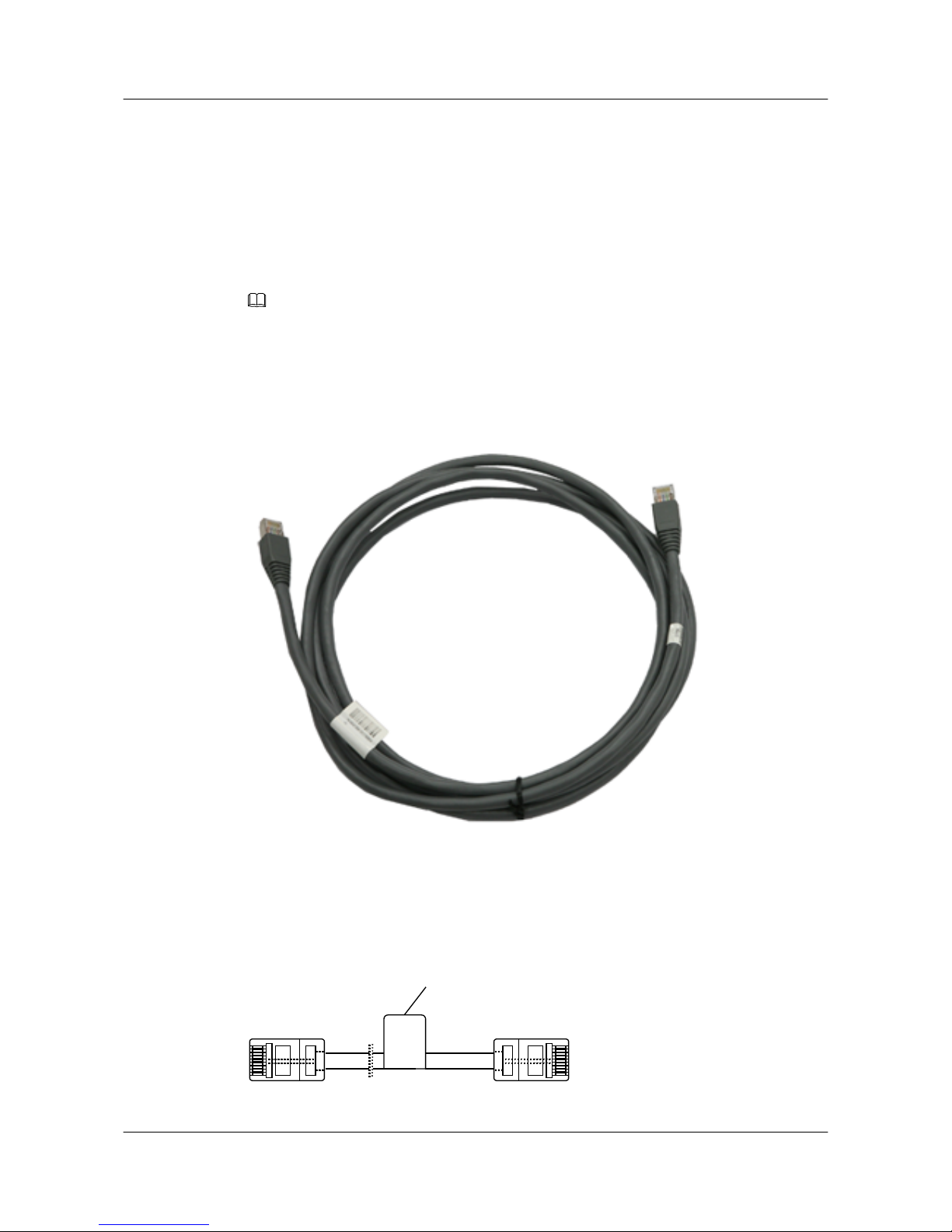
The network cables are classified into straight through cables and crossover cables.
l A straight through cable connects a terminal, such as a computer or switch, to the network.
The straight through cable uses two RJ45 connectors, which have the same pinout.
l A crossover cable connects two terminals, such as computers or switches. The crossover
cable uses two RJ45 connectors, which have difference pinouts.
Appearance and Structure
NOTE
l Generally, a network cable is a standard unshielded network cable that uses RJ45 connectors.
l The appearances of the straight through cable and the crossover cable are the same.
Figure 5-7 shows the appearance of a network cable.
Figure 5-7 Appearance of a network cable
Figure 5-8 shows the appearance of a network cable.
Figure 5-8 Structure of a network cable
Main label
X1
X2
S5700&S5710 Series Ethernet Switches
Hardware Description 5 Cables
Issue 01 (2012-03-15) Huawei Proprietary and Confidential
Copyright © Huawei Technologies Co., Ltd.
85
Page 94
Pin Assignments
Table 5-7 describes the pin assignments of a straight through cable.
Table 5-7 Pin assignments of a straight through cable
X1 Pin Tip Color X2 Pin
1 White and orange 1
2 Orange 2
3 White and Green 3
4 Blue 4
5 White and Blue 5
6 Green 6
7 White and brown 7
8 Brown 8
Table 5-8 describes the pin assignments of a crossover cable.
Table 5-8 Pin assignments of a crossover cable
X1 Pin
Tip Color X2 Pin
1 White and orange 3
2 Orange 6
3 White and Green 1
4 Blue 4
5 White and Blue 5
6 Green 2
7 White and brown 7
8 Brown 8
NOTE
To achieve the optimum electrical transmission performance, ensure that the wires connected to pins 1 and 2
and to pins 3 and 6 are twisted pairs.
S5700&S5710 Series Ethernet Switches
Hardware Description 5 Cables
Issue 01 (2012-03-15) Huawei Proprietary and Confidential
Copyright © Huawei Technologies Co., Ltd.
86
Page 95

Specifications
Table 5-9 lists the specifications of a network cable.
Table 5-9 Specifications of a network cable
Item Description
Connector type (X1/X2) RJ45 connectors
Cable type Category-3 and category-5 unshielded twisted pairs
(UTP-3 and UTP-5) or shielded twisted pairs (STP)
Color Dark gray
Characteristic impedance 100.0 Ω
Diameter 0.510 mm
Breakdown voltage 500.0 V
Impedance 93.8 Ω
Pin 8 pins
Frequency 0 MHz to 100 MHz
Frequency attenuation 22 dB/100 m@100 MHz
Fireproof level CM
Length
l Straight through cable: 5 m, 10 m, 20 m, and 30 m
l Crossover cable: 5 m and 30 m
5.7 Optical Fibers
An optical fiber connects the optical interface of a device to an upstream device or optical
network terminal.
Applications
An optical fiber carries optical signals and transmits them over short distance. An optical fiber
connects the following:
l Optical interface on a board
l Optical distribution frame (ODF) or the optical interface on another device
Table 5-10 lists the classification of optical fibers.
S5700&S5710 Series Ethernet Switches
Hardware Description 5 Cables
Issue 01 (2012-03-15) Huawei Proprietary and Confidential
Copyright © Huawei Technologies Co., Ltd.
87
Page 96
Table 5-10 Optical fiber classification
No. Purpose Local End
Connector
Remote End
Connector
Mode
1 To connect LPU of the
device to the ODF
LC/PC FC/PC Single mode,
indoor
2 To connect LPUs of two
devices
LC/PC LC/PC Single mode/
multimode,
indoor
3 To connect LPU of the
device to another device
LC/PC SC/PC or LC/PCSingle mode/
multimode,
indoor
Appearance
The appearances of the single-mode optical fiber and the multimode optical fiber are the same,
but their colors are different. The single-mode optical fiber is yellow, and the multi-mode optical
fiber is orange.
CAUTION
When connecting or removing the LC/PC optical connector, align the connector with the optical
interface, and do not rotate the fiber. Pay attention to the following points:
l Align the head of the fiber jumper with the optical interface and insert the optical fiber into
the interface gently.
l To remove the fiber, press the latch on the connector and pull the fiber out.
Figure 5-9 and Figure 5-10 show the appearances of a single mode fiber.
S5700&S5710 Series Ethernet Switches
Hardware Description 5 Cables
Issue 01 (2012-03-15) Huawei Proprietary and Confidential
Copyright © Huawei Technologies Co., Ltd.
88
Page 97
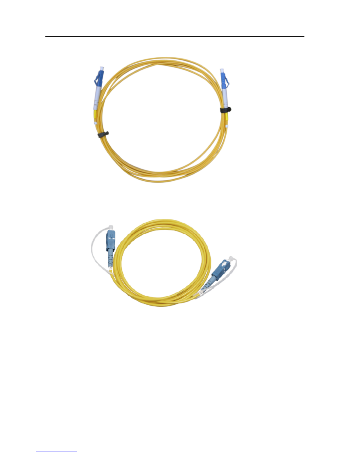
Figure 5-9 Single mode fiber with LC/PC connectors
Figure 5-10 Single mode fiber with SC/PC connectors
Figure 5-11 shows the appearance of a multimode fiber.
S5700&S5710 Series Ethernet Switches
Hardware Description 5 Cables
Issue 01 (2012-03-15) Huawei Proprietary and Confidential
Copyright © Huawei Technologies Co., Ltd.
89
Page 98
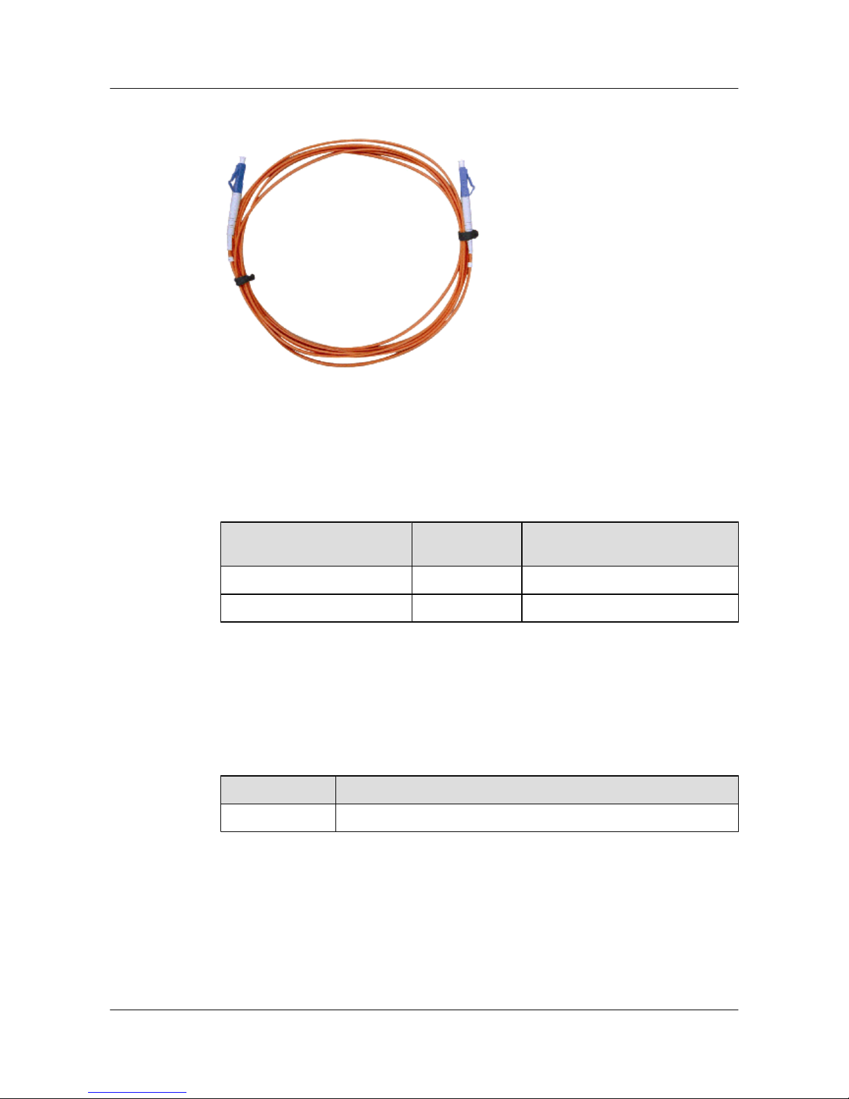
Figure 5-11 Multimode fiber with LC/PC connectors
Pin Assignments
Table 5-11 describes the pin assignments of an optical fiber.
Table 5-11 Pin assignments of an optical fiber
Local End Terminal
Signal
Direction
Remote End Terminal
Optical interface Tx terminal -> Optical interface Rx terminal
Optical interface Rx terminal <- Optical interface Tx terminal
Fiber Selection Criterion
Table 5-12 lists the criteria for selecting optical fibers. Table 5-13 lists common optical
connectors.
Table 5-12 Fiber selection criterion
Parameter
Criterion
Length Survey result
S5700&S5710 Series Ethernet Switches
Hardware Description 5 Cables
Issue 01 (2012-03-15) Huawei Proprietary and Confidential
Copyright © Huawei Technologies Co., Ltd.
90
Page 99
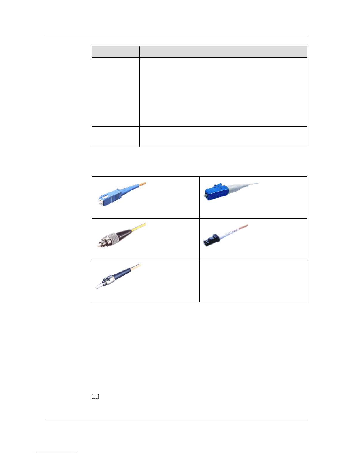
Parameter Criterion
Single mode or
multimode
Optical module type
l The optical transmitting module of the multitransverse mode is
connected to the multimode fiber.
l The optical transmitting module of the single-longitudinal mode or
multi-longitudinal mode is connected to the single mode fiber.
NOTE
If the optical fiber jumper is used, the connector connected to the device must be
the LC/PC connector, and the connector connected to the remote end must be of
the same type as the remote end interface.
Connector shape
l Cube: SC/PC, LC/PC, and MTRJ/PC
l Column: ST/PC and FC/PC
Table 5-13 Common optical connectors
SC/PC optical connector
LC/PC optical connector
FC/PC optical connector
MTRJ/PC optical connector
ST/PC optical connector
-
5.8 Stack cables
This section describes the structure and technical specifications of a stack cable.
Applications
The S5700 uses PCI-E cables or SFP+ stack cables to connect stack interfaces on the ETPC card
or the specified interfaces. The S5700s connected with stack cables form a logical switch to
forward packets.
NOTE
The two ends of a stack cable are covered by ESD caps.
S5700&S5710 Series Ethernet Switches
Hardware Description 5 Cables
Issue 01 (2012-03-15) Huawei Proprietary and Confidential
Copyright © Huawei Technologies Co., Ltd.
91
Page 100
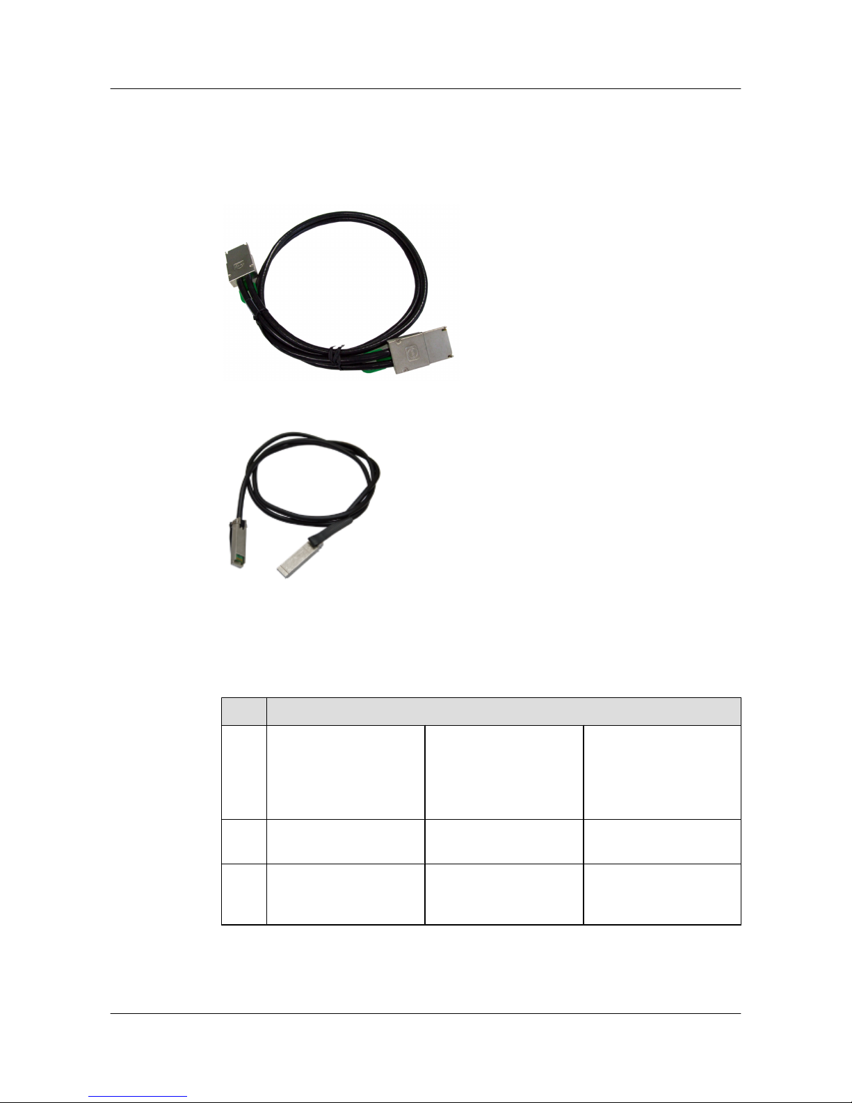
Appearance and Structure
The structure of a stack cable is shown in Figure 5-12 and Figure 5-13.
Figure 5-12 Structure of a PCI-E cable
Figure 5-13 Structure of an SFP+ cable
Specifications
Table 5-14 and Table 5-15 list the specifications of a stack cable.
Table 5-14 Specifications of an SFP+ cable
Item
Description
Cabl
e
type
SFP+ high-speed
transmission cable,
indoor, (SFP+ 20 male),
(SFP+ 20 male), SFP+,
(CC2P0.254 black)-1.0 m
SFP+ high-speed
transmission cable,
indoor, (SFP+ 20 male),
(SFP+ 20 male), SFP+,
(CC2P0.254 black)-3.0 m
SFP+ high-speed
transmission cable,
indoor, (SFP+ 20 male),
(SFP+ 20 male), SFP+,
(CC2P0.5 black)-10.0 m
Length1.0 m 3.0 m 10.0m
Bend
radiu
s
25 mm 25 mm 30 mm
S5700&S5710 Series Ethernet Switches
Hardware Description 5 Cables
Issue 01 (2012-03-15) Huawei Proprietary and Confidential
Copyright © Huawei Technologies Co., Ltd.
92
 Loading...