

Page 1
Page
1
of 34HEEX Startpage
12/10/2015
http://localhost:7890/printtopics.html?time=Thu Dec 10 16:53:17 UTC
-
0200 2015
S2700&S3700 Product Documentation
Product Version: V100R006C05
Library Version: 03
Date: 01/20/2014
For any question, please
Copyright © Huawei Technologies Co., Ltd. 2014. All rights reserved.
S2700 Product Description
Contents
1.4.1.1
S2700 Product Description
1.4.1.1.1
1.4.1.1.2
1.4.1.1.2.1
1.4.1.1.2.2
About This Document
Product Positioning and Characteristics
Product Positioning
Product Characteristics
1.4.1.1.2.2.1
1.4.1.1.2.2.2
1.4.1.1.2.2.3
1.4.1.1.2.2.4
1.4.1.1.2.2.5
1.4.1.1.2.2.6
1.4.1.1.2.2.7
1.4.1.1.3
1.4.1.1.3.1
1.4.1.1.3.2
1.4.1.1.3.3
Product Architecture
Introduction
Device Architecture
Hardware Modules
1.4.1.1.3.3.1
1.4.1.1.3.3.2
1.4.1.1.3.3.3
1.4.1.1.3.4
1.4.1.1.4
1.4.1.1.4.1
Software Architecture
Link Features
Ethernet Features
1.4.1.1.4.1.1
1.4.1.1.4.1.2
1.4.1.1.4.1.3
1.4.1.1.4.1.4
1.4.1.1.4.1.5
1.4.1.1.4.1.6
1.4.1.1.4.2
STP/RSTP/MSTP
1.4.1.1.4.2.1
1.4.1.1.4.2.2
1.4.1.1.4.2.3
1.4.1.1.4.2.4
1.4.1.1.4.3
1.4.1.1.4.4
Interface Security
Link Detection
Flexible Networking Capability
High Extensibility
Comprehensive Security Measures
Convenient Operation and Maintenance
Energy-Saving Design
Advanced Lightning Protection Technologies
Intelligent PoE Power Supply
SCU
Power Supply
Fan
Link Aggregation
Flow Control on an Interface
Traffic Suppression
VLAN
QinQ
GVRP
STP and RSTP
MSTP
MSTP Protection
Partitioned STP and BPDU Tunnel
contact us
.
Page 2

1.4.1.1.5
Page
2
of 34HEEX Startpage
12/10/2015
http://localhost:7890/printtopics.html?time=Thu Dec 10 16:53:17 UTC
-
0200 2015
Service Features
1.4.1.1.5.1
1.4.1.1.5.2
1.4.1.1.5.2.1
1.4.1.1.5.2.2
1.4.1.1.5.2.3
1.4.1.1.5.2.4
1.4.1.1.5.2.5
1.4.1.1.5.3
1.4.1.1.5.3.1
1.4.1.1.5.3.2
1.4.1.1.5.3.3
1.4.1.1.5.3.4
1.4.1.1.5.3.5
1.4.1.1.5.3.6
1.4.1.1.5.4
1.4.1.1.5.4.1
1.4.1.1.5.4.2
1.4.1.1.5.4.3
1.4.1.1.5.5
1.4.1.1.5.6
1.4.1.1.5.7
1.4.1.1.5.8
1.4.1.1.8
System Technical Specifications
1.4.1.1.8.1
1.4.1.1.8.2
1.4.1.1.8.3
1.4.1.1.8.4
IPv6
Multicast
IGMP Snooping
IGMP Snooping Proxy
Prompt Leave of Multicast Member Interfaces
Multicast Traffic Control
Controllable Multicast
QoS
Traffic Classification
Access Control and Re-marking
Traffic Policing
Congestion Management
Rate Limit on an Interface
Aggregate CAR
Security
Device Security
Service Security
Security Authentication
MAC-Forced Forwarding
Reliability
LLDP
Stacking
Physical Specifications
Optical Module Attributes
System Configuration
List of Software Features
1.4.1.1 S2700 Product Description
About This Document
Product Positioning and Characteristics
Product Architecture
Link Features
Service Features
Networking and Applications
Maintenance and Network Management System
System Technical Specifications
Parent topic:
Product Description
1.4.1.1.1 About This Document
Page 3
Purpose
Page
3
of 34HEEX Startpage
12/10/2015
http://localhost:7890/printtopics.html?time=Thu Dec 10 16:53:17 UTC
-
0200 2015
This document describes the positioning, characteristics, architecture, link features, service features, application
scenarios, operation and maintenance functions, and technical specifications of the S2700.
This document helps you understand the characteristics and features of the S2700.
Intended Audience
This document is intended for:
Network planning engineers
Hardware installation engineers
Commissioning engineers
Data configuration engineers
On-site maintenance engineers
Network monitoring engineers
System maintenance engineers
Statement
The device provides the mirroring function for network monitoring and fault management, during which
communication data of users may be collected. Huawei alone is unable to collect or save the content of users'
communications. It is suggested that you activate the interception-related functions based on the applicable laws
and regulations in terms of purpose and scope of usage. You are obligated to take considerable measures to
ensure that the content of users' communications is fully protected when the content is being used and saved.
Symbol Conventions
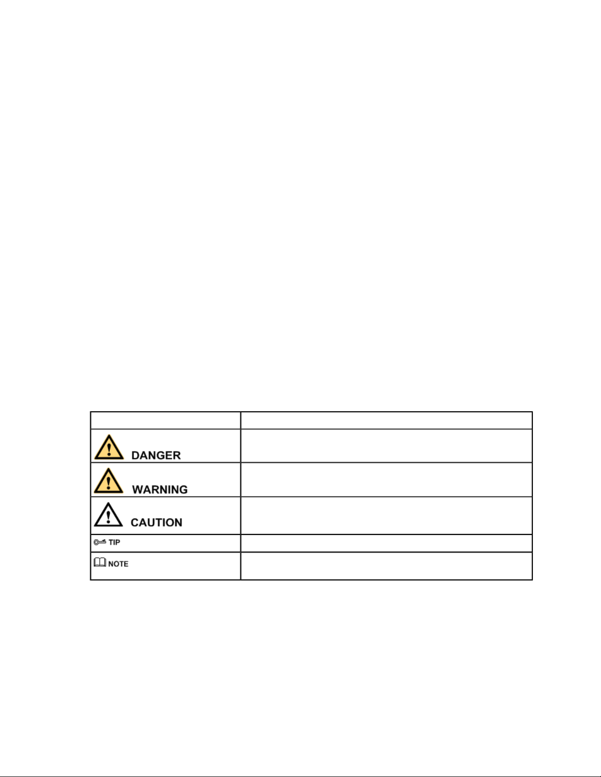
The symbols that may be found in this document are defined as follows.
Symbol Description
Indicates a hazard with a high level or medium level of risk which, if not
avoided, could result in death or serious injury.
Indicates a hazard with a low level of risk which, if not avoided, could result in
minor or moderate injury.
Indicates a potentially hazardous situation that, if not avoided, could result in
equipment damage, data loss, performance deterioration, or unanticipated
results.
Provides a tip that may help you solve a problem or save time.
Provides additional information to emphasize or supplement important points
in the main text.
Change History
Updates between document issues are cumulative. Therefore, the latest document version contains all updates
made to previous versions.
Changes in Issue 03 (2014-01-20)
The third commercial release has the following updates:
Some contents are optimized.
Page 4
Changes in Issue 02 (2013-04-20)
Page
4
of 34HEEX Startpage
12/10/2015
http://localhost:7890/printtopics.html?time=Thu Dec 10 16:53:17 UTC
-
0200 2015
The second commercial release has the following updates:
The documentation is modified according to updates in product features.
Changes in Issue 01 (2013-02-08)
Initial commercial release.
Parent topic:
S2700 Product Description
1.4.1.1.2 Product Positioning and Characteristics
Product Positioning
Product Characteristics
Parent topic:
S2700 Product Description
1.4.1.1.2.1 Product Positioning
NOTICE:
The S2700 Series Ethernet Switches are class A products. The switches that are operating may cause radio
interference. Customers need to take prevention measures.
The S2700 Series Ethernet Switches (hereinafter referred to as the S2700) provide the access and data transport
functions. They are developed by Huawei to meet the requirements for reliable access and high-quality
transmission of multiple services on the enterprise network.
Positioned for the access layer of the enterprise network, the S2700 provides large capacity, high port density,
and cost-effective packet forwarding capabilities. In addition, the S2700 provides multi-service access
capabilities, excellent extensibility, quality of service (QoS) guarantee, powerful multicast replication, and
carrier-class security, and can be used to build ring topologies of high reliability.
Parent topic:
Product Positioning and Characteristics
1.4.1.1.2.2 Product Characteristics
Flexible Networking Capability
High Extensibility
Comprehensive Security Measures
Convenient Operation and Maintenance
Energy-Saving Design
Page 5

Advanced Lightning Protection Technologies
Page
5
of 34HEEX Startpage
12/10/2015
http://localhost:7890/printtopics.html?time=Thu Dec 10 16:53:17 UTC
-
0200 2015
Intelligent PoE Power Supply
Parent topic:
Product Positioning and Characteristics
1.4.1.1.2.2.1 Flexible Networking Capability
The S2700 provides 10/100BASE-T Ethernet electrical interfaces, 10/100/1000BASE-T electrical interfaces, and
100/1000BASE-X Ethernet optical interfaces. It supports multiple interface types such as access, trunk, and
hybrid.
The S2700 provides swappable Small Form-Factor Pluggable (SFP) optical modules for optical fiber
connections.The length of optical fibers can be selected according to the transmission distance.
The S2700 can be used to construct a tree, star, or ring Ethernet network. For the ring Ethernet, the S2700
supports the Spanning Tree Protocol (STP) to prevent loops and provide rapid switchover.
Parent topic:
Product Characteristics
1.4.1.1.2.2.2 High Extensibility
Based on the Huawei proprietary Versatile Routing Platform (VRP), the S2700 provides high-speed switching
and various service features by integrating network management technologies.
Parent topic:
Product Characteristics
1.4.1.1.2.2.3 Comprehensive Security Measures
The S2700 guarantees the security of network devices and data transmission. It provides the following security
measures to protect the network against attacks initiated by malicious users:
Packet filtering based on MAC addresses
Various ACL policies
Mechanism of searching the forwarding table based on VLAN IDs and MAC addresses
Traffic suppression
In addition, the S2700 provides the following functions to ensure secure login of users:
Providing login passwords and password encryption for login users
Protecting commands through users levels and command levels
Locking the configuration terminal through a certain command to prevent illegal use of the device
Displaying confirm or prompt information for important commands that affect system performance
The S2700 provides the Automatic Laser Shutdown (ALS) function. That is, when the fiber is broken, the S2700
stops transmitting laser. This protects users against the laser.
Page 6

Parent topic:
Page
6
of 34HEEX Startpage
12/10/2015
http://localhost:7890/printtopics.html?time=Thu Dec 10 16:53:17 UTC
-
0200 2015
Product Characteristics
1.4.1.1.2.2.4 Convenient Operation and Maintenance
In addition to collecting traffic statistics based on interfaces and VLANs, the S2700 provides fault detection and
location tools such as ping and traceroute on an IP network. It can also work with the Huawei eSight network
management system (NMS) to implement performance monitoring, alarm report, and fast fault location.
eSight provides various functions to help you manage the S2700, including resource management, topology
management, and configuration file management, batch configuration. In addition, eSight can show important
performance indicators in diagrams and tables to facilitate device management.
Parent topic:
Product Characteristics
1.4.1.1.2.2.5 Energy-Saving Design
The S2700 adopts the following measures to save energy:
It adopts natural heat dissipation so that power consumed by fans is saved.
NOTE:
Currently, The S2700-9TP-PWR-EI, S2700-9TP-SI/EI, S2700-18TP-SI/EI, and SS2700-26TP-SI/EI supports natural heat
dissipation.
The chip switches to the power saving mode when no connected device is detected on a service interface, that
is, the interface is idle.
It uses highly-integrated and energy-saving chips produced through advanced processing techniques. With the
help of the intelligent device management system, the chips not only improve system performance but also
greatly reduce power consumption of the entire system.
Natural heat dissipation has the following advantages:
The product reliability is high.
There is no noise pollution.
You do not need to maintain the fans, which saves the maintenance cost.
The system does not have additional power consumption generated by fans, which improves the power
efficiency.
Boards are prevented from being eroded.
Parent topic:
Product Characteristics
1.4.1.1.2.2.6 Advanced Lightning Protection
Technologies
The S2700 adopts the Huawei patented lightning protection technologies to protect the equipment. The lightning
Page 7

protection technologies reduce the probability of damages caused by lightning and increase the safety factor by
Page
7
of 34HEEX Startpage
12/10/2015
http://localhost:7890/printtopics.html?time=Thu Dec 10 16:53:17 UTC
-
0200 2015
30 times, thus greatly improving the device reliability.
Parent topic:
Product Characteristics
1.4.1.1.2.2.7 Intelligent PoE Power Supply
The S2700 PoE switches has the PoE function. It provides centralized power supply for the attached IP phone,
wireless access point (AP), portable device charger, POS machine, camera, and data collector through twisted
pairs.
The PoE function of the S2700 PoE switches complies with IEEE 802.3af and IEEE 802.3at. The S2700 can
provide power for the devices of different vendors remotely. In IEEE 802.3at, the maximum power supply
capability is 30 W. This capability ensures adequate power for IP video phone, dualband WiFi AP, IP camera,
multi-function STB11, and RFID and simplifies the network.
The S2700 PoE switches has the ability to control power supply based on time range, thus effectively managing
network devices, reducing power consumption, and lowering the OPEX.
Parent topic:
Product Characteristics
1.4.1.1.3 Product Architecture
Introduction
Device Architecture
Hardware Modules
Software Architecture
Parent topic:
S2700 Product Description
1.4.1.1.3.1 Introduction
The S2700 series adopt the integrated hardware platform and have the front-access structure. The hardware
consists of the chassis, power supply, fan, and SCU. The width of the S2700 complies with the industry
standards, and the S2700 can be installed in an IEC 297 cabinet or an ETSI cabinet.
The S2700 series include the S2700-9TP-SI-AC, S2700-9TP-EI-AC, S2700-9TP-EI-DC, S2700-18TP-SI-AC,
S2700-18TP-EI-AC, S2700-26TP-SI-AC, S2700-26TP-EI-AC, S2700-26TP-EI-DC, S2700-52P-EI-AC, S27009TP-PWR-EI, S2710-52P-SI-AC, S2710-52P-PWR-SI, S2700-52P-PWR-EI and S2700-26TP-PWR-EI.
Parent topic:
Product Architecture
1.4.1.1.3.2 Device Architecture
Page 8
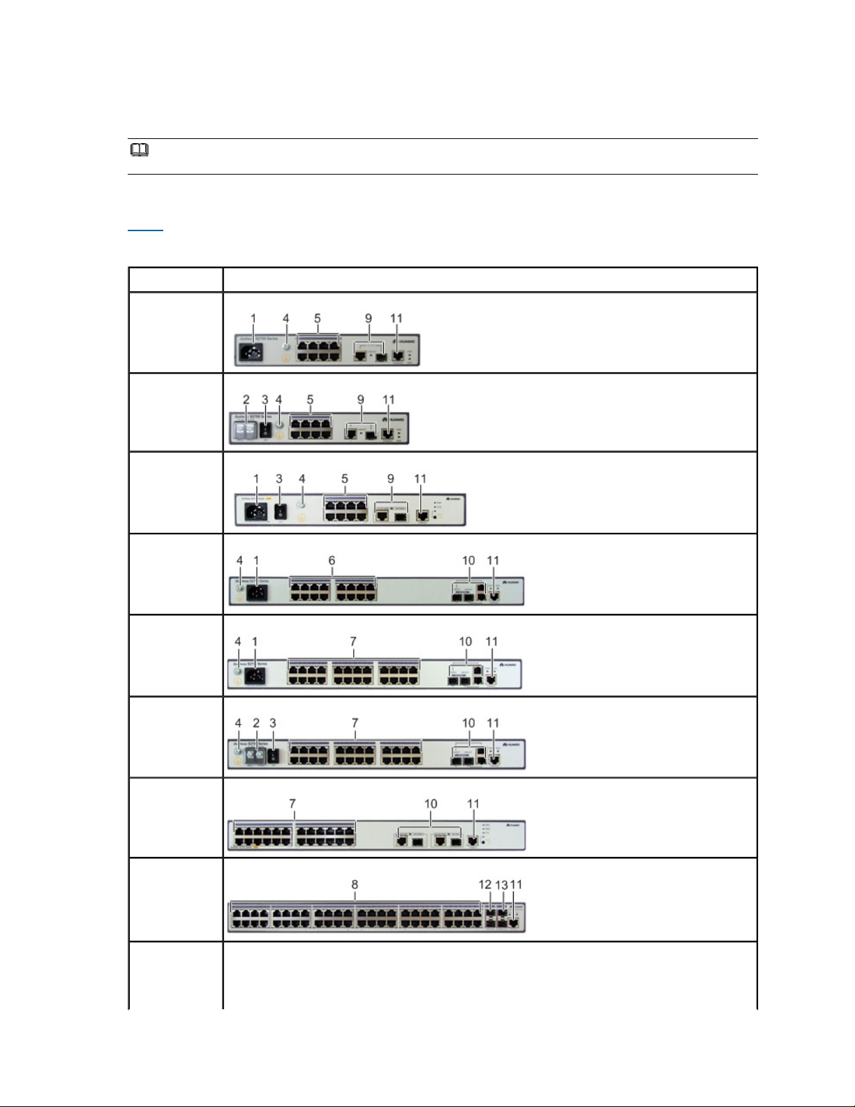
The S2700 Ethernet switches adopt an integrated hardware platform. An S2700 consists of the chassis, power
Page
8
of 34HEEX Startpage
12/10/2015
http://localhost:7890/printtopics.html?time=Thu Dec 10 16:53:17 UTC
-
0200 2015
supply unit, fan, and switch control unit (SCU).
NOTE:
The figures in this document are for reference only.
S2700 Appearances
Table 1
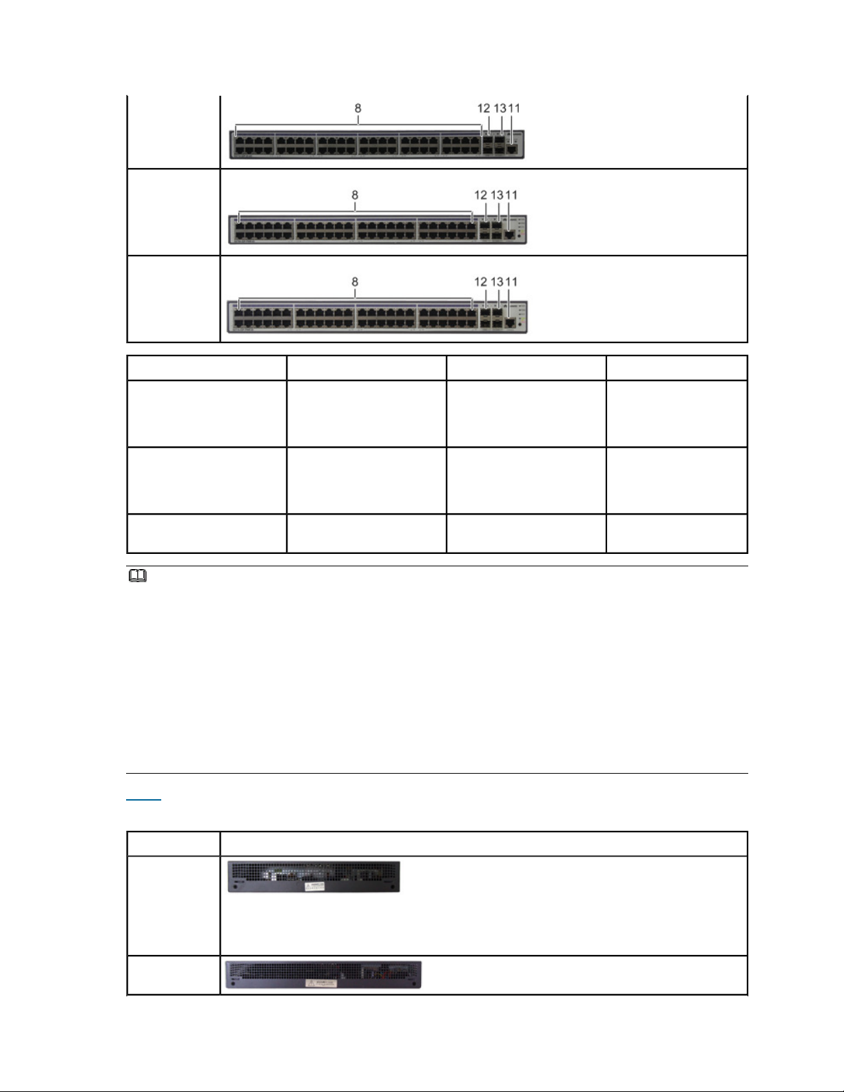
shows the front views of S2700.
Table 1 S2700 front views
Model Image
S2700-9TP-SIAC
S2700-9TP-EIAC
S2700-9TP-EIDC
S2700-9TPPWR-EI
S2700-18TP-SIAC
S2700-18TP-EIAC
S2700-26TP-SIAC
S2700-26TP-EIAC
S2700-26TP-EIDC
S2700-26TPPWR-EI
S2700-52P-EIAC
S2710-52P-SIAC
Page 9
Page
9
of 34HEEX Startpage
12/10/2015
http://localhost:7890/printtopics.html?time=Thu Dec 10 16:53:17 UTC
-
0200 2015
S2700-52PPWR-EI
S2710-52PPWR-SI
1. AC jack 2. DC terminal 3. Switch 4. Ground screw
5. Eight 10/100BASE-TX
Ethernet electrical interfaces
6. Sixteen 10/100BASE-TX
Ethernet electrical interfaces
7. Twenty-four 10/100BASETX Ethernet electrical
interfaces
8. Forty-eight
10/100BASE-TX
Ethernet electrical
interfaces
9. One 1000M combo
interface
(10/100/1000BASET+100/1000BASE-X)
13. Two 100/1000BASE-X
10. Two 1000M combo
11. One console interface 12. Two 1000BASE-X
interfaces
(10/100/1000BASET+100/1000BASE-X)
Ethernet optical interfaces
Ethernet optical interfaces
NOTE:
By default, a combo port works in auto mode, in which the port type is determined as follows:
If the optical port has no optical module installed and the electrical port has no network cable connected, the port type depends on
which port is connected first. If the electrical port is connected by a network cable first, the electrical port is used for data switching.
If the optical port has an optical module installed first, the optical port is used for data switching.
If the electrical port has a network cable connected and is in Up state, the electrical port is still used for data switching when the
optical port has an optical module installed.
If the optical port, no matter in Up or Down state, has an optical module installed, the optical port is still used for data switching
when the electrical port has a network cable connected.
If the optical port has an optical module installed and the electrical port has a network cable connected, the optical port is used for
data switching after the switch restarts.
You can configure a combo port as an electrical or optical port using the combo-port command.
Table 2
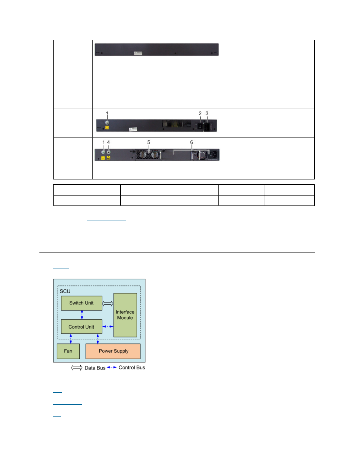
shows the rear views of S2700.
Table 2 S2700 rear views
Model Image
S2700-9TP-SIAC
S2700-9TP-EIAC
S2700-9TP-EIDC
S2700-9TPPWR-EI
Page 10
S2700-18TP-SI-
Page
10
of 34HEEX Startpage
12/10/2015
http://localhost:7890/printtopics.html?time=Thu Dec 10 16:53:17 UTC
-
0200 2015
AC
S2700-18TP-EI-
AC
S2700-26TP-SI-
AC
S2700-26TP-EI-
AC
S2700-26TP-EI-
DC
S2700-52P-EIAC
S2710-52P-SIAC
S2700-26TPPWR-EI
S2700-52PPWR-EI
S2710-52PPWR-SI
1. Ground screw 2. Switch 3. AC jack 4. ESD jack
5. Fan module 6. Power supply unit slot
Parent topic:
Product Architecture
1.4.1.1.3.3 Hardware Modules
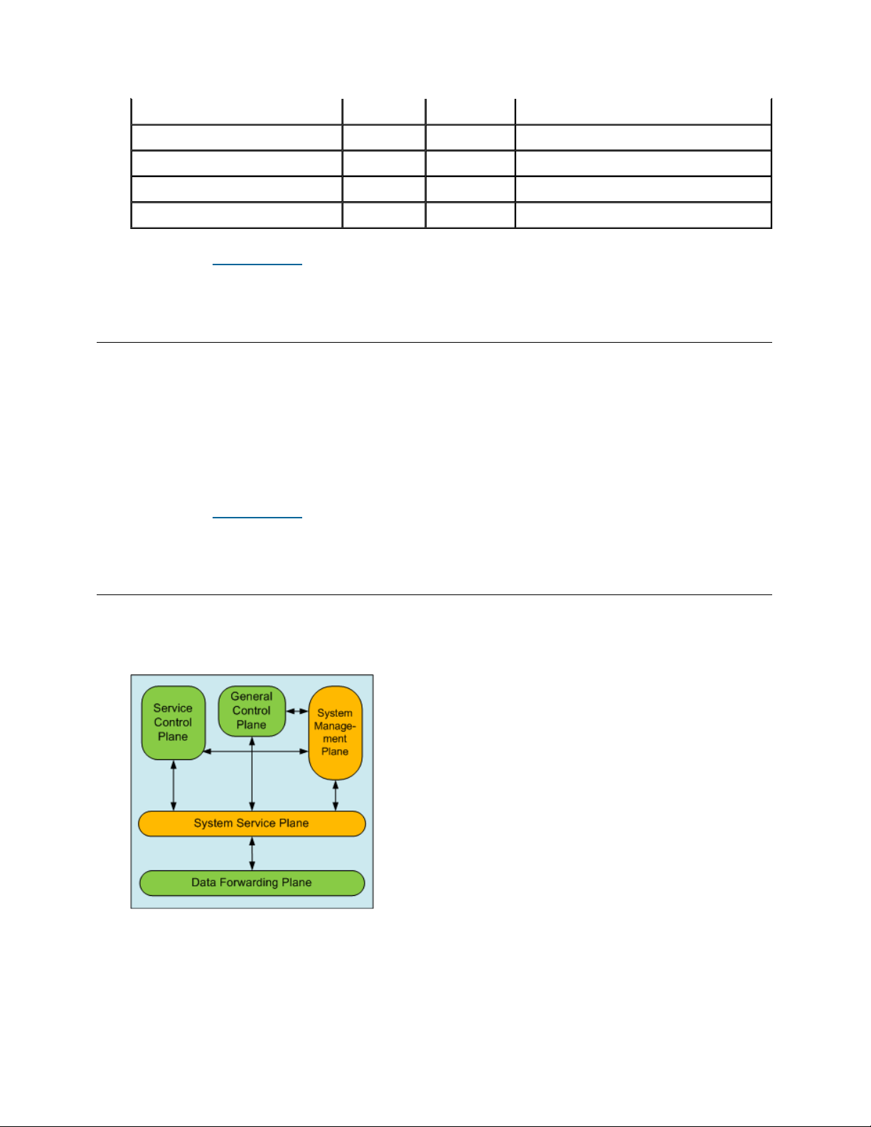
Figure 1
shows the logical structure of hardware modules of the S2700.
Figure 1 Logical structure of hardware modules of the S2700
Hardware modules of the S2700 refer to the SCU, power supply, and fan.
SCU
Power Supply
Fan
Page 11

Parent topic:
Page
11
of 34HEEX Startpage
12/10/2015
http://localhost:7890/printtopics.html?time=Thu Dec 10 16:53:17 UTC
-
0200 2015
Product Architecture
1.4.1.1.3.3.1 SCU
The SCU is fixed on the S2700. Each S2700 has one SCU.
The SCU is responsible for packet switching and device management. It integrates multiple functional modules,
namely, the main control module, switching module, and interface module.
Main Control Module
The main control module implements the following functions:
Processing protocols
Functioning as an agent of the user to manage the system and monitor the system performance according to
instructions of the user, and report the running status of the device to the user
Monitoring and maintaining the interface module and switching module on the SCU.
Switching Module
The switching module, also called the switching fabric, is responsible for packet exchange, multicast replication,
QoS scheduling, and access control on the interface module of the SCU.
The switching module adopts high performance ASIC chips to implement line-speed forwarding and fast
switching of data with different priorities.
Interface Module
The interface module provides Ethernet interfaces for accessing Ethernet services.
Parent topic:
Hardware Modules
1.4.1.1.3.3.2 Power Supply
Table 1 Power supply
Device Name AC DC 1:1 Backup power supplies
S2700-9TP-SI-AC
S2700-9TP-EI-AC
S2700-9TP-EI-DC
S2700-18TP-SI-AC
S2700-18TP-EI-AC
S2700-26TP-SI-AC
S2700-26TP-EI-AC
S2700-26TP-EI-DC
S2700-52P-EI-AC
Y N N
Y N N
N Y N
Y
Y N N
Y N N
Y N N
N Y N
Y
N
N
N
N
Page 12
S2710-52P-SI-AC
Page
12
of 34HEEX Startpage
12/10/2015
http://localhost:7890/printtopics.html?time=Thu Dec 10 16:53:17 UTC
-
0200 2015
S2700-9TP-PWR-EI
S2700-26TP-PWR-EI
S2700-52P-PWR-EI
S2710-52P-PWR-SI
Y N N
Y N N
Y N Y
Y N Y
Y N Y
Parent topic:
Hardware Modules
1.4.1.1.3.3.3 Fan
The fans can work in the intelligent mode or forcible mode.
In the intelligent mode, the fans start to operate only when the environment temperature exceeds a specified
value.
The S2700-52P-EI-AC, S2710-52P-SI-AC support the intelligent mode.
The S2700-26TP-PWR-EI, S2710-52P-PWR-SI and S2700-52P-PWR-EI support the hot pluggable fans. The
fan module can be replaced on site and maintained in service.
Parent topic:
Hardware Modules
1.4.1.1.3.4 Software Architecture
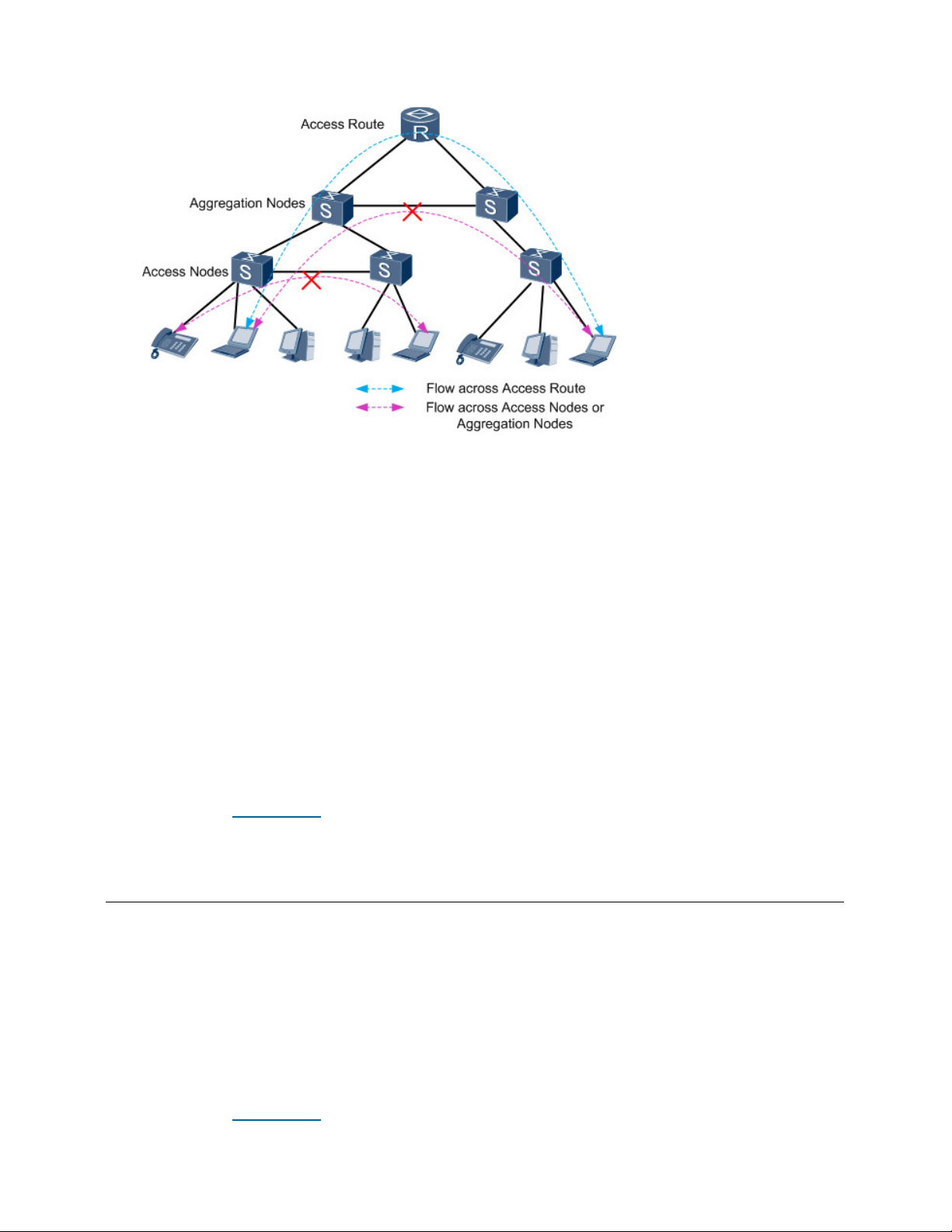
The S2700 runs on the latest VRP version 5 (VRPv5) to provide various features. VRPv5 consists of the
following parts:
Figure 1 Software architecture
System service plane
This plane provides task and memory management, timer, software loading and patching on the basis of the
operating system. In addition, it enhances modular technology to facilitate system upgrade and customization.
General control plane
This plane is the core of the VRP data communication platform, providing link management, IP protocol
Page 13

stack, and implementing the security and QoS functions. It is used to control the data forwarding plane and
Page
13
of 34HEEX Startpage
12/10/2015
http://localhost:7890/printtopics.html?time=Thu Dec 10 16:53:17 UTC
-
0200 2015
implement functions of the device.
Data forwarding plane
This plane forwards data under the control of the general control plane. The VRPv5 supports data forwarding
based on software and hardware.
Service control plane
This plane controls and manages services based on users or interfaces. It implements the authentication,
authorization, and accounting for users through DHCP Option 82 and implements authentication for access
interfaces through IEEE 802.1x.
System management plane
This plane provides a graphic user interface and manages the input and output information for network
management and maintenance.
Parent topic:
Product Architecture
1.4.1.1.4 Link Features
Ethernet Features
STP/RSTP/MSTP
Interface Security
Link Detection
Parent topic:
S2700 Product Description
1.4.1.1.4.1 Ethernet Features
Link Aggregation
Flow Control on an Interface
Traffic Suppression
VLAN
QinQ
GVRP
Parent topic:
Link Features
1.4.1.1.4.1.1 Link Aggregation
Page 14

Link aggregation is a function that binds multiple physical interfaces on one device into a logical interface (such
Page
14
of 34HEEX Startpage
12/10/2015
http://localhost:7890/printtopics.html?time=Thu Dec 10 16:53:17 UTC
-
0200 2015
as an Eth-Trunk). This logical interface is also called a load balancing group or a link aggregation group.
After multiple physical interfaces are bound into a logical interface, the S2700 load balances the traffic passing
through the logical interface among the member interfaces. When a member interface fails, the traffic on this
interface is shared by the other member interfaces without interrupting services. When the faulty interface
recovers, the traffic is balanced among all interfaces again.
Currently, the S2700 implements link aggregation between GE interfaces or FE interfaces. Load balancing can
be implemented based on the following information:
Source MAC address
Destination MAC address
Source MAC address and destination MAC address
Using the link aggregation technology, you can increase the bandwidth and improve link reliability without
upgrading the hardware, thus saving costs.
Parent topic:
Ethernet Features
1.4.1.1.4.1.2 Flow Control on an Interface
Flow control on an interface is a method of congestion management. It applies to all types of flows. The S2700
implements flow control on an interface by using the hardware backpressure mechanism. When an interface
works in full duplex mode, the S2700 implements flow control complying with IEEE 802.3x. When the interface
works in half duplex mode, the S2700 implements flow control through the backpressure mechanism.
When congestion occurs, the S2700 sends continuous Pause frames to the upstream device, requesting it to stop
sending data for a specified period of time. When the upstream device receives the pause frames, it reduces the
volume of traffic sent from its outbound interface. Flow control on an interface does not identify flow types.
Parent topic:
Ethernet Features
1.4.1.1.4.1.3 Traffic Suppression
Traffic suppression limits the number of unknown unicast packets, multicast packets, and broadcast packets
within a proper range to ensure network efficiency.
The S2700 can suppress the packets based on interfaces. When traffic suppression is enabled on an interface, the
interface monitors received unknown unicast packets, multicast packets, and broadcast packets to check whether
their traffic exceeds the threshold. If traffic exceeds the threshold, the S2700 discards excessive packets to keep
the traffic volume within the limit and thus services on the network run normally.
The S2700 can also control the percentage of unknown unicast packets, multicast packets, and broadcast packets
on an interface.
Parent topic:
Ethernet Features
1.4.1.1.4.1.4 VLAN
Page 15

A local area network (LAN) can be divided into several logical LANs. Each logical LAN is a broadcast domain,
Page
15
of 34HEEX Startpage
12/10/2015
http://localhost:7890/printtopics.html?time=Thu Dec 10 16:53:17 UTC
-
0200 2015
which is called a virtual LAN (VLAN). To put it simply, devices on a LAN are logically grouped into different
LAN segments, irrespective of their physical locations. In this manner, VLANs isolate broadcast domains on a
LAN.
Methods to Define VLANs
A physical LAN can be divided into several VLANs, and several physical LANs can be grouped into a VLAN.
Devices on a VLAN belong to the same broadcast domain and can communicate with each other. Different
VLANs are isolated from each other, so devices on different VLANs cannot communicate with each other.
The S2700 supports the following methods to define VLANs:
Based on interfaces
After an interface is added to a VLAN, packets received by the interface are sent on the VLAN.
Based on MAC addresses
VLAN members are defined according to source MAC addresses of packets. When an interface of the S2700
receives a packet, the S2700 determines the VLAN ID of the packet according to the source MAC address of
the packet and sends the packet on the corresponding VLAN.
NOTE:
The S2700SI and S2710SI do not support defining VLANs based on MAC addresses.
Voice VLAN
A voice VLAN is used to transmit voice data flows. You can create a voice VLAN and add the interface
connected to the voice device to the voice VLAN. Then voice data flows can be transmitted on the voice VLAN.
You can apply special QoS configuration to the voice data packets transmitted on the voice VLAN so that voice
data packets are transmitted with high priority. The quality of the voice service is ensured.
NOTE:
The S2700SI and S2710SI do not support the Voice VLAN.
VLAN Mapping
VLAN mapping means that the S2700 replaces the outer VLAN tags of data frames to the specified VLAN tags
according to the preset VLAN mapping table so that services are transmitted according to the network planning
of the carrier.
The S2700 supports the mapping from one or more customer VLAN IDs (C-VLANs) to a service VLAN ID (SVLAN).
NOTE:
C-VLAN is the VLAN that a user-side interface belongs to. It identifies a user or a type of users.
An S-VLAN is a VLAN defined on the public network by the carrier. The S-VLAN ID identifies a service.
The S2700SI and S2710SI do not support the VLAN Mapping.
Parent topic:
Ethernet Features
1.4.1.1.4.1.5 QinQ
Page 16

NOTE:
Page
16
of 34HEEX Startpage
12/10/2015
http://localhost:7890/printtopics.html?time=Thu Dec 10 16:53:17 UTC
-
0200 2015
The S2700SI does not support the QinQ.
The 802.1Q-in-802.1Q (QinQ) protocol is a Layer 2 tunneling protocol based on the IEEE 802.1Q. A frame
transmitted on the public network has double 802.1Q tags. One tag identifies the public network and the other
identifies the private network.
Usually, carriers define VLANs on the public network, and users define VLANs on their own private networks.
Therefore, different private networks may use the same VLAN ID. Through the QinQ function, the S2700 adds
public VLAN tags to the packets from private networks. Then the private VLAN tag becomes the inner VLAN
tag. In this way, packets from user networks are transmitted transparently on the public network, and thus user
networks are separated from the public network.
The S2700 supports the basic QinQ function. That is, all the frames that reach the public network through an
interface are tagged with the same public VLAN ID.
Parent topic:
Ethernet Features
1.4.1.1.4.1.6 GVRP
NOTE:
The S2700SI does not support the GVRP.
GVRP is a protocol used for dynamic registration and deregistration of VLANs. GVRP maintains the dynamic
VLAN registration information in a switch and propagates the registration information to other switches on the
network through GARP.
GVRP enables switches on the network to dynamically maintain and update VLANs. With GVRP, you do not
need to expend time to analyze the topology and manage configurations. You can adjust the VLAN deployment
on the entire network by configuring only a few devices.
The S2700 supports GARP and GVRP. Through GVRP, the S2700 can send VLAN declaration to other devices
and dynamically create VLANs after receiving VLAN registration information from other devices.
Parent topic:
Ethernet Features
1.4.1.1.4.2 STP/RSTP/MSTP
STP and RSTP
MSTP
MSTP Protection
Partitioned STP and BPDU Tunnel
Parent topic:
Link Features
1.4.1.1.4.2.1 STP and RSTP
Page 17

The Spanning Tree Protocol (STP) and the Rapid Spanning Tree Protocol (RSTP) are link-layer management
Page
17
of 34HEEX Startpage
12/10/2015
http://localhost:7890/printtopics.html?time=Thu Dec 10 16:53:17 UTC
-
0200 2015
protocols and are mainly applied to LANs to prevent loops. STP blocks redundant links and trims a network into
a tree topology free from loops. RSTP enhances STP. It provides fast transition of interfaces status to speed up
network convergence.
STP and RSTP prevent broadcast storms caused by loops and provides backup links for data forwarding.
Parent topic:
STP/RSTP/MSTP
1.4.1.1.4.2.2 MSTP
NOTE:
The S2700SI does not support MSTP.
The Multiple Spanning Tree Protocol (MSTP) is developed based on STP and RSTP. MSTP divides a network
into multiple regions. Based on VLAN tags, each region has several spanning trees that are independent of each
other. As a result, the entire network is trimmed to a tree topology that is free from loops. Broadcast storms are
thus prevented on the network.
MSTP associates VLANs with spanning trees so that packets of different VLANs are transmitted along different
spanning trees. This speeds up network convergence and implements load balancing.
Different from STP and RSTP, MSTP provides multiple backup links to implement load balancing among
VLANs.
Parent topic:
STP/RSTP/MSTP
1.4.1.1.4.2.3 MSTP Protection
BPDU Protection
The S2700 provides Bridge Protocol Data Unit (BPDU) protection when MSTP is enabled. When BPDU
protection is enabled, the S2700 shuts down the edge port that receives a protocol BPDU instead of turning the
edge port into a non-edge port. In this case, the spanning tree is not recalculated, and thus network flapping is
prevented.
Root Protection
The S2700 provides root protection when MSTP is enabled. It retains the role of the root switch by maintaining
the role of the designated port as follows:
When the designated port enabled with root protection receives a BPDU of higher priority, the port does not
change to a non-designated port. Instead, it turns to the Listening state and stops forwarding packets. If the port
does not receive protocol BPDUs of higher priority for a long time, it restores the Forwarding state. This
prevents network flapping.
Loop Protection
After loop protection is enabled on the S2700, it sets the root port to the Blocking state if the root port does not
receive protocol BPDUs from the upstream device. If the port receives protocol BPDUs again, it becomes the
root port and changes to the Forwarding state. If no protocol BPDU is received, the port remains in the Blocking
state and does not forward packets. In this way, loops are prevented on the network.
Page 18

Parent topic:
Page
18
of 34HEEX Startpage
12/10/2015
http://localhost:7890/printtopics.html?time=Thu Dec 10 16:53:17 UTC
-
0200 2015
STP/RSTP/MSTP
1.4.1.1.4.2.4 Partitioned STP and BPDU Tunnel
Partitioned STP
To improve the reliability of links on the enterprise network, the S2700 can be dual-homed to the upstream
Ethernet. In addition, MSTP needs to run on the whole enterprise network to prevent loops. The traditional
MSTP networks are not divided. In this case, the convergence speed of an MSTP network is low because the
network is large. As a result, the forwarding capability of the network is degraded.
By using the partitioned STP technology, the S2700 logically allocates a VLAN for each partitioned STP
network. The tagged BPDUs can be forwarded only within the VLAN that the tag belongs to. Partitioned STP
allows BPDUs to be transmitted within a certain range. This prevents loops and speeds up convergence.
BPDU Tunnel
On a partitioned STP network, the S2700 considers the tagged BPDUs as common Layer 2 frames. That is, the
S2700 forwards the BPDUs within the VLAN to which the tag belongs rather than sending them to the MSTP
module. After the BPDU tunnel is configured, the devices on the MAN do not participate in the topology
calculation of the partitioned STP network. Thus, the convergence speed of the network is improved.
To implement the BPDU tunnel function, the access device at the edge of the MAN must be configured with
MSTP Snooping. If the forwarding path is changed because of the topology change on the partitioned STP
network, the device can detect the topology change, and then notify other devices on the network of the topology
change. In this way, the packets are forwarded according to the new topology.
NOTE:
The S2700SI does not support the BPDU Tunnel.
Parent topic:
STP/RSTP/MSTP
1.4.1.1.4.3 Interface Security
Interface security is a security mechanism to control the access to a network. It checks whether the source MAC
addresses of data frames received on an interface are valid. When detecting packets with invalid source MAC
addresses, it takes certain actions to protect the interface.
After security protection is enabled on an interface, the S2700 considers the following types of MAC addresses
valid:
Static MAC addresses that are manually configured
Dynamic or static MAC addresses in the DHCP snooping table
Dynamic MAC addresses that are learned before the number of learned MAC addresses reaches the limit
When the interface receives frames with invalid source MAC addresses, the S2700 triggers the interface security
function to discard the frames or generates an alarm according to the configuration.
Parent topic:
Link Features
Page 19

1.4.1.1.4.4 Link Detection
Page
19
of 34HEEX Startpage
12/10/2015
http://localhost:7890/printtopics.html?time=Thu Dec 10 16:53:17 UTC
-
0200 2015
Link detection includes loopback detection and virtual cable test (VCT). They provide users with two means to
detect link faults on LANs.
Loopback detection is used to check whether loops exist on a LAN. The S-switch sends specific packets to
detect loopback on the entire LAN.
VCT is mainly used to estimate the length of a network cable and locate the failure point of the cable. The Sswitch simulates radar to detect cable faults and locate the failure points on the basis of a single link.
Parent topic:
Link Features
1.4.1.1.5 Service Features
IPv6
Multicast
QoS
Security
MAC-Forced Forwarding
Reliability
LLDP
Stacking
Parent topic:
S2700 Product Description
1.4.1.1.5.1 IPv6
The S2700 provides the IPv6 host function, which protects the investment of customers and prevents repeat
investment during network upgrade.
The IPv6 functions supported by the S2700 include:
IPv6 protocol stack
ND, ICMP v6, Traceroute v6, Telnet v6, DNS, and IPv6 static route
Simple IPv6 ACL
NOTE:
The S2700SI does not support the IPv6 ACL.
Parent topic:
Service Features
Page 20

1.4.1.1.5.2 Multicast
Page
20
of 34HEEX Startpage
12/10/2015
http://localhost:7890/printtopics.html?time=Thu Dec 10 16:53:17 UTC
-
0200 2015
The Internet Group Management Protocol (IGMP) is a protocol used to manage IP multicast members. It sets up
and maintains the member relationship between IP hosts and their directly connected multicast routers.
IGMP Snooping
IGMP Snooping Proxy
Prompt Leave of Multicast Member Interfaces
Multicast Traffic Control
Controllable Multicast
Parent topic:
Service Features
1.4.1.1.5.2.1 IGMP Snooping
Located between hosts and a multicast router, the S2700 supports static multicast forwarding entries and
generates a dynamic Layer 2 multicast forwarding table with multicast groups and outbound interfaces by
listening to IGMP messages.
When the S2700 receives a multicast packet, it forwards the packet only to the members on the VLAN
corresponding to the multicast group. The multicast packet is transmitted in multicast mode on the VLAN
according to the Layer 2 multicast forwarding table. This saves bandwidth and enhances the security of
information transfer.
Parent topic:
Multicast
1.4.1.1.5.2.2 IGMP Snooping Proxy
IGMP Snooping proxy is deployed on the switch that is located between the router and hosts. Then the switch
serves as an agent server. The switch terminates IGMP protocol packets sent by hosts to the router and responds
to the IGMP Query messages for the hosts. In addition, the switch processes IGMP protocol packets sent by the
router and the hosts. In this manner, the forwarding entries for Layer 2 multicast are created.
Parent topic:
Multicast
1.4.1.1.5.2.3 Prompt Leave of Multicast Member
Interfaces
When a multicast member leaves a multicast group, the host sends an IGMP Leave message. When an interface
on the S2700 is connected to only one host, the S2700 deletes the multicast forwarding entry of the interface
immediately after receiving the IGMP Leave message. This saves bandwidth and system resources and
Page 21

implements fast switching of services.
Page
21
of 34HEEX Startpage
12/10/2015
http://localhost:7890/printtopics.html?time=Thu Dec 10 16:53:17 UTC
-
0200 2015
Parent topic:
Multicast
1.4.1.1.5.2.4 Multicast Traffic Control
Unknown multicast packets refer to the multicast packets that do not have forwarding entries in the Layer 2
multicast forwarding table. When receiving unknown multicast packets, the S2700 discards the packets or
broadcasts them on the VLAN that the inbound interface belongs to.
The S2700 can also control inbound multicast traffic volume by limiting the percentage of multicast packets on
an Ethernet interface.
Parent topic:
Multicast
1.4.1.1.5.2.5 Controllable Multicast
Multicast protocols do not provide user authentication. Therefore, a user can join or leave a multicast group
freely. The multicast source does not know when a user joins or leaves a multicast group, so the number of users
receiving multicast traffic on a network in a certain period is unknown. Therefore, the carrier cannot perform
accounting for the users. The controllable multicast technology is introduced to solve these problems. Users have
to pass authentication before receiving multicast traffic. Furthermore, only authorized multicast traffic can be
received by users. Users who pass authentication are allowed to preview unauthorized multicast traffic and can
receive multicast traffic in specified periods within a day. Controllable multicast does not apply to static
multicast.
Parent topic:
Multicast
1.4.1.1.5.3 QoS
The S2700 provides the class-based QoS mechanism and supports the 802.1p priority. It provides guarantee of
low end-to-end delay, jitter, and high bandwidth.
The S2700 classifies traffic according to certain rules and then performs corresponding actions on the packets
such as priority re-marking, traffic policing, congestion management, congestion avoidance, and rate limit on the
interface. In this way, value-added services such as NGN services, IPTV, and broadband access are provided
with better network service.
Traffic Classification
Access Control and Re-marking
Traffic Policing
Congestion Management
Rate Limit on an Interface
Aggregate CAR
Page 22

Parent topic:
Page
22
of 34HEEX Startpage
12/10/2015
http://localhost:7890/printtopics.html?time=Thu Dec 10 16:53:17 UTC
-
0200 2015
Service Features
1.4.1.1.5.3.1 Traffic Classification
Traffic classification is a function of identifying the packets of a certain type by matching information in the
packet header. For example, the 802.1p priority of the packets sent by the Operating Support System (OSS) and
NMS is set to 7; the 802.1p priority of VoIP packets is set to 6; the 802.1p priority of BTV packets and VOD
packets is set to 5 or 4; the 802.1p priority of packets sent by VPN users is set to 3, 2, or 1 according to the level
of VPN users; the 802.1p priority of packets of the Internet access service is set to 0. Then the packets can be
classified based on their 802.1p priorities.
The S2700 adopts a hardware classifier to guarantee line-speed transmission of services data on interfaces.
Simple Traffic Classification
On the S2700, you can perform simple traffic classification for packets according to the mapping between
priorities of packets and Per-Hop Behaviors (PHBs). If packets come from an upstream device, the S2700 maps
priorities of the packets to PHBs and colors. On the S2700, congestion management is performed for packets
according to PHBs of packets and congestion avoidance is performed for packets according to colors of packets.
The downstream device provides QoS services according to the priorities of packets.
The S2700 only supports simple traffic classification according to the 802.1p priority of VLAN packets.
Complex Traffic Classification
NOTE:
The S2700SI does not support complex traffic classification.
You can perform complex traffic classification according to Layer 2 or Layer 3 information in packets or
through access control lists (ACLs). Then, you can bind a traffic classifier to a traffic behavior to process packets
matching the traffic classifier.
The traffic behavior adopted is related to the current phase of packets and the current load of a network. For
example, when packets enter an S2700, the S2700 performs traffic policing and access control for the packets
according to the committed information rate (CIR); when packets exit an S2700, the S2700 shapes the traffic of
packets and re-marks the priorities of packets.
Complex traffic classification is based on:
802.1p priority of VLAN packets
VLAN ID of packets
Incoming interface
Source MAC address
Destination MAC address
Protocol type field encapsulated in Layer 2 packets
Layer 3 protocol type
IP quintuple
Parent topic:
QoS
Page 23

1.4.1.1.5.3.2 Access Control and Re-marking
Page
23
of 34HEEX Startpage
12/10/2015
http://localhost:7890/printtopics.html?time=Thu Dec 10 16:53:17 UTC
-
0200 2015
After traffic classification, the S2700 performs access control on the packets, that is, permits or denies the
packets. Then, the S2700 re-marks the following fields in the packets:
802.1p field, that is, the PRI field in a VLAN tag
DSCP field
Local precedence
VLAN ID, that is, the outer VLAN ID or inner VLAN ID of QinQ packets
Parent topic:
QoS
1.4.1.1.5.3.3 Traffic Policing
The S2700 uses the token bucket algorithm to control the Committed Access Rate (CAR) of network traffic.
The S2700 controls the rate of traffic by adjusting the rate of placing tokens. Each token equals a forwarding rate
of 64 kbit/s. The S2700 "punishes" the excessive traffic to limit the incoming traffic within a proper range and to
protect the network resources.
Parent topic:
QoS
1.4.1.1.5.3.4 Congestion Management
The S2700 manages traffic congestion through queue scheduling. Each outbound interface on the S2700 is
configured with four queues. After traffic classification, packets are sent to the corresponding queues based on
their priorities.
The S2700 provides the following queue scheduling policies:
Priority Queuing(PQ)
Weight Round Robin(WRR)
Deficit Round Robin(DRR)
PQ + WRR
PQ + DRR
Parent topic:
QoS
1.4.1.1.5.3.5 Rate Limit on an Interface
Rate limit on an interface is used to adjust the rate of traffic on an outbound interface or inbound interface to
prevent burst traffic. The S2700 uses the token bucket and a buffer to limit the traffic rate on an outbound
Page 24

interface, implementing traffic shaping. When the rate of packets exceeds the rate limit, the S2700 buffers
Page
24
of 34HEEX Startpage
12/10/2015
http://localhost:7890/printtopics.html?time=Thu Dec 10 16:53:17 UTC
-
0200 2015
excessive packets and sends them when the traffic rate falls below the limit. In this manner, the transmission rate
is smoothed.
Parent topic:
QoS
1.4.1.1.5.3.6 Aggregate CAR
Aggregate CAR is the CAR applied to multiple interfaces to implement traffic policing for service flows on the
interfaces. The sum of rate limits on the interfaces must be equal to or smaller than the aggregate CAR.
Parent topic:
QoS
1.4.1.1.5.4 Security
The S2700 guarantees both device security and service security.
Device Security
Service Security
Security Authentication
Parent topic:
Service Features
1.4.1.1.5.4.1 Device Security
Hierarchical Command Protection
When a user logs in to the S2700 from an Ethernet interface through Telnet, the S2700 authenticates the user to
ensure security. The user can configure and maintain the S2700 only after passing the authentication.
The S2700 adopts a hierarchical protection mode for commands. Commands are classified into the visit level,
monitoring level, configuration level, and management level, with their levels in ascending order. Login users
are also classified into four levels, corresponding to the four levels of commands. After logging in to the S2700,
a user can run only the commands at the same or lower level. This mode effectively controls the user authority.
The S2700 extends command levels and user levels to 16 levels so that users are managed more refinedly.
Remote SSH Login
The S2700 supports the Secure Shell (SSH). On an insecure network, SSH provides powerful security guarantee
and authentication for login users and can defend against various attacks.
Encrypted Authentication Through SNMPv3
The S2700 supports encrypted authentication through SNMPv3. When S2700 is managed by an NMS
workstation through SNMP, it adopts the encrypted authentication mode in user-based security mode (USM) to
ensure security.
Page 25

AAA
Page
25
of 34HEEX Startpage
12/10/2015
http://localhost:7890/printtopics.html?time=Thu Dec 10 16:53:17 UTC
-
0200 2015
The S2700 supports the Authentication, Authorization, and Accounting (AAA). Using AAA and hierarchical
command protection, the S2700 can authenticate and authorize login users. In addition, it can authenticate the
NMS administrator. AAA effectively prevents unauthorized users from logging in to the S2700.
The S2700 supports authentication methods such as local authentication, RADIUS authentication, and
HWTACAS+ authentication.
CPU Channel Protection
The S2700 can filter the protocol packets and management packets sent to the CPU based on the protocol ID,
interface, and combination of interface and VLAN. This protects the CPU channels against Denial of Service
(DoS) attacks.
Limit of MAC Address Learning on Interfaces
You can set the maximum number of MAC addresses learned by an interface on the S2700 to prevent hackers
from initiating source MAC address attack from the interface. This ensures that the MAC address entries of the
S2700 will not be used up.
Parent topic:
Security
1.4.1.1.5.4.2 Service Security
VLAN
The S2700 supports the division of a LAN into multiple VLANs. Devices on different VLANs cannot
communicate with each other. This isolates broadcast domains and improves service security.
Blackhole MAC Address Entry
The S2700 supports blackhole MAC address entries. When receiving a packet, the S2700 compares the source or
destination MAC address of the packet with its MAC address entries. If the source or destination MAC address
of packet is the same as a blackhole MAC address, the S2700 discards the packet.
When detecting attacking packets from a MAC address, you can set a blackhole MAC address entry on the
S2700 to filter out the packets with the MAC address.
MAC Table Searching Based on VLAN+MAC
The S2700 supports MAC table searching based on VLANs and MAC addresses to improve interface security.
You can add static MAC address entries in the MAC table to map specific MAC addresses to interfaces. In this
way, specific devices are bound to interfaces so that hackers cannot attack the S2700 by using fake MAC
addresses.
Port Isolation
Port isolation prevents ports on the same S2700 from sending Layer 2 packets to each other. The S2700 supports
unidirectional and bidirectional port isolation. Port isolation ensures security of user networks and helps to
construct low-cost intelligent community networks. Port isolation also limits unnecessary broadcast packets and
thus increases network throughput.
Packet Filtering
Packet filtering is used to filter out invalid or unwanted packets.
The S2700 filters packets based on user-defined rules. For example, it filters packets by checking the MAC
address, IP address, port number, and VLAN ID of packets. Packet filtering does not check the session status or
analyze the data. By filtering packets, the S2700 can effectively control the packets passing through it.
Page 26

Parent topic:
Page
26
of 34HEEX Startpage
12/10/2015
http://localhost:7890/printtopics.html?time=Thu Dec 10 16:53:17 UTC
-
0200 2015
Security
1.4.1.1.5.4.3 Security Authentication
The 802.1x protocol is a port-based network access control protocol. It authenticates and controls access devices
on a LAN based on interfaces. A user device can access resources on the LAN only after it passes the
authentication on the access interface.
MAC address-based authentication controls the network access authority of a user based on the access interface
and MAC address of the user. The user does not need to install any authentication client software. After
detecting the MAC address of the user for the first time, the device starts authenticating the user. During the
authentication, the user does not need to enter the user name or password.
NOTE:
The S2700SI does not support the Security Authentication.
Parent topic:
Security
1.4.1.1.5.5 MAC-Forced Forwarding
NOTE:
The S2700SI does not support the MAC-Forced Forwarding.
The access layer provides network connections between the user-side hosts and the enterprise-side access routers
(ARs), especially the reliable connections between the hosts with the Internet or other IP networks.
The access layer can be divided into the user network and convergence network. The user network is connected
to the access node (AN) through a subscriber line, which is a physical line and usually called "the first mile."
The subscriber line is then connected to the convergence network through the AN. In this manner, the AN is the
border between the subscriber line and the convergence network. User traffic is centralized and aggregated on
the convergence network, which is usually called "the second mile." For details, see
Figure 1 Connections at the access layer
Figure 1
.
Page 27
Page
27
of 34HEEX Startpage
12/10/2015
http://localhost:7890/printtopics.html?time=Thu Dec 10 16:53:17 UTC
-
0200 2015
At the access layer, the enterprise has the following requirements:
In order that the enterprise uses the AR to perform secure filtering, policy scheduling, and accounting for the
traffic, the ARs need to perform Layer 3 forwarding for the traffic of different user hosts in different
networks. The ARs, however, cannot forward packets through Layer 2 switching.
The efficiency of address assignment needs to be improved to save IPv4 addresses. The effectiveness of
address assignment needs to be improved if an address is assigned from a large address pool rather than a
small and independent network segment to the host.
To implement user isolation at the access layer and meet the preceding requirements of the enterprise, the MACForced Forwarding (MFF) protocol is introduced.
MFF is a security protocol that isolates the user hosts accessing the same device. When MFF is running, its
security program applies to any shared access media, bringing no extra problems to these networks.
In addition to Layer 2 isolation, the AN that runs MFF discards any upstream broadcast packets except for
DHCP packets and ARP request packets. The AN discards DHCP response packets received through the
subscriber line and limits the rate of DHCP broadcast packets.
The AN that runs MFF must know the IPv4 addresses allocated to the subscriber line. This is to discard the
upstream traffic with the fake IPv4 source addresses.
Parent topic:
Service Features
1.4.1.1.5.6 Reliability
The S2700 supports MSTP to eliminate broadcast storms on a network and provide backup links for data
transmission.
The S2700 provides the root protection function. When the designated port receives a BPDU of higher priority,
it remains the designated port for a certain period of time to protect the role of the root switch. This prevents the
network topology from changing by mistake.
The S2700 provides the loop protection function. When the root port cannot receive any BPDU from the
upstream device, it enters the Blocking state and stops forwarding packets. At the same time, no new root port is
elected. This prevents loops on the network.
Parent topic:
Service Features
Page 28

1.4.1.1.5.7 LLDP
Page
28
of 34HEEX Startpage
12/10/2015
http://localhost:7890/printtopics.html?time=Thu Dec 10 16:53:17 UTC
-
0200 2015
The S2700 supports the Link Layer Discovery Protocol (LLDP) that conforms to IEEE 802.1ab. LLDP is a link
layer protocol used for interconnected devices to obtain the connection information of each other.
Using LLDP, the local NMS can obtain the link layer information of all devices on the local network and details
about the network topology. Thus the NMS can manage a larger area on the network.
The LLDP-enabled interfaces on the S2700 periodically notify the neighbors of its own status. If the status of an
interface changes, the interface sends status update messages to the directly connected neighboring device. The
neighboring device stores the status update message in the standard SNMP MIB. Then the NMS can obtain the
link layer information of the network from the MIB to calculate the topology of the entire network.
Parent topic:
Service Features
1.4.1.1.5.8 Stacking
Stacking means that the switches located in the same place are connected through the stacking cable or highspeed uplink interfaces, and thus the switches form a reliable switch group. In a switch group, the S2700s are
connected through the stack interfaces multiplexed with uplink GE interfaces. Through stacking, the user can
manage and maintain the switches uniformly; therefore, the stacking reduces the maintenance cost of the
user.The stacked switches must be of the same type.
Parent topic:
Service Features
1.4.1.1.8 System Technical Specifications
Physical Specifications
Optical Module Attributes
System Configuration
List of Software Features
Parent topic:
S2700 Product Description
1.4.1.1.8.1 Physical Specifications
Table 1 Physical specifications
Item Description
Dimensions (width x depth x height)
S2700-9TP-SI-AC: 250.0 mm x 180.0 mm x 43.6 mm
S2700-9TP-EI-AC: 250.0 mm x 180.0 mm x 43.6 mm
S2700-9TP-EI-DC: 250.0 mm x 180.0 mm x 43.6 mm
Page 29

Page
29
of 34HEEX Startpage
12/10/2015
http://localhost:7890/printtopics.html?time=Thu Dec 10 16:53:17 UTC
-
0200 2015
S2700-18TP-SI-AC: 442.0 mm x 220.0 mm x 43.6 mm
S2700-18TP-SI-DC: 442.0 mm x 220.0 mm x 43.6 mm
S2700-26TP-SI-AC: 442.0 mm x 220.0 mm x 43.6 mm
S2700-26TP-EI-AC: 442.0 mm x 220.0 mm x 43.6 mm
S2700-26TP-EI-DC: 442.0 mm x 220.0 mm x 43.6 mm
S2700-52P-EI-AC: 442.0 mm x 220.0 mm x 43.6 mm
S2700-9TP-PWR-EI: 320.0 mm x 220.0 mm x 43.6 mm
S2700-26TP-PWR-EI: 442.0 mm x 420.0 mm x 43.6 mm
S2700-52P-PWR-EI: 442.0 mm x 420.0 mm x 43.6 mm
S2710-52P-SI-AC: 442.0 mm x 220.0 mm x 43.6 mm
S2710-52P-PWR-SI: 442.0 mm x 420.0 mm x 43.6 mm
Maximum power (full configuration)
Weight
Mean time between failures (MTBF)
S2700-9TP-SI-AC: 12.8 W
S2700-9TP-EI-AC: 12.8 W
S2700-9TP-EI-DC: 12.8 W
S2700-18TP-SI-AC: 14.5 W
S2700-18TP-SI-DC: 14.5 W
S2700-26TP-SI-AC: 15.5 W
S2700-26TP-EI-AC: 15.5 W
S2700-26TP-EI-DC: 15.5 W
S2700-52P-EI-AC: 38 W
S2700-9TP-PWR-EI: 154 W (Device power: 30 W, PoE: 124 W)
S2700-26TP-PWR-EI: 808 W (Device power: 68 W, PoE: 740 W)
S2700-52P-PWR-EI: 880 W (Device power: 128 W, PoE: 740 W)
S2710-52P-SI-AC: 38 W
S2710-52P-PWR-SI: 880 W (Device power: 128 W, PoE: 740 W)
Non-PWR: ≤ 3.5 kg
PWR: ≤ 8 kg
S2700-9TP-SI-AC: 44.1 years
S2700-9TP-EI-AC: 44.1 years
S2700-9TP-EI-DC: 44.1 years
S2700-18TP-SI-AC: 39.2 years
S2700-18TP-EI-AC: 39.2 years
S2700-26TP-SI-AC: 37.3 years
S2700-26TP-EI-AC: 37.3 years
S2700-26TP-EI-DC: 37.3 years
S2700-52P-EI-AC: 26.8 years
S2700-9TP-PWR-EI: 35.5 years
S2700-26TP-PWR-EI: 34.8 years
S2700-52P-PWR-EI: 35.4 years
S2710-52P-SI-AC: 26.8 years
S2710-52P-PWR-SI: 35.4 years
Mean time to repair (MTTR) 2 hours
Availability > 0.99999
Surge protection Service port
protection
Power supply
protection
Non-PoE switch: ±6 kV in common mode
PoE switch: ±1 kV in common mode
AC: S2700-9TP-SI-AC, S2700-9TP-EI-AC, S2700-18TP-SI-AC,
S2700-18TP-EI-AC, S2700-26TP-SI-AC, and S2700-26TP-EIAC: ±6 kV in differential mode; ±6 kV in common mode; others:
±2 kV in differential mode; ±4 kV in common mode
DC: ±1 kV in differential mode; ±2 kV in common mode
Page 30

DC input voltage Rated voltage -48V DC to -60V DC
Page
30
of 34HEEX Startpage
12/10/2015
http://localhost:7890/printtopics.html?time=Thu Dec 10 16:53:17 UTC
-
0200 2015
Maximum
voltage
AC input voltage Rated voltage 100V AC to 240V AC
Maximum
voltage
Temperature operating
temperature
Storage
temperature
Relative humidity 5%RH to 95%RH, non-condensing
Altitude S2700-9TP-SI-AC, S2700-9TP-EI-AC, S2700-18TP-SI-AC, S2700-
Parent topic:
System Technical Specifications
-36V DC to -72V DC
90V AC to 264V AC
-5°C to 50°C
NOTE:
S2700-52P-PWR-EI, S2710-52P-PWR-SI: 0°C to 50°C
-40°C to +70°C
18TP-EI-AC, S2700-26TP-SI-AC, and S2700-26TP-EI-AC: 0 m to
5000 m; others: 0 m to 2000 m
1.4.1.1.8.2 Optical Module Attributes
Table 1 Attributes of the SFP (FE) optical module
Attribute Specification
Transmission
distance
Center wavelength 1310 nm
Transmitting power -19.0 dBm to -14.0 dBm
Receiver sensitivity -30.0 dBm
Overload power -14.0 dBm
Extinction ratio 10 dB
Type of the optical
connector
Fiber type Multi-mode
2 km
LC
Table 2 Attributes of the ESFP (FE) optical module
Attribute Specification
Transmission
distance
15 km 15 km (single-
mode
bidirectional
fiber)
15 km (singlemode
bidirectional
fiber)
40 km 80 km
Center wavelength 1310 nm Sending: 1310 nm
Receiving: 1550
nm
Sending: 1550 nm
Receiving: 1310
nm
1310 nm 1550 nm
Page 31

Transmitting power -15.0 dBm to -8.0
Page
31
of 34HEEX Startpage
12/10/2015
http://localhost:7890/printtopics.html?time=Thu Dec 10 16:53:17 UTC
-
0200 2015
dBm
Receiver sensitivity -31.0 dBm -32.0 dBm -32.0 dBm -34.0 dBm -34.0 dBm
Overload power -8.0 dBm -8.0 dBm -8.0 dBm -10.0 dBm -10.0 dBm
Extinction ratio 8.2 dB 8.5 dB 8.5 dB 10.0 dB 10.0 dB
-15.0 dBm to -8.0
dBm
-15.0 dBm to -8.0
dBm
-5.0 dBm to 0
dBm
-5.0 dBm to 0
dBm
Type of the optical
connector
Fiber type Single mode Single mode Single mode Single mode Single mode
LC LC/PC LC/PC LC LC
Table 3 Attributes of the ESFP (GE) optical module
Attribute Specification
Transmission
distance
Center
wavelength
Transmitting
power
Receiver
sensitivity
Overload
power
0.5
km
850
nm
-9.5
dBm
to -
2.5
dBm
-17.0
dBm
0
dBm
10 km 10 km
(singlemode
bidirectional
fiber)
1310
Sending:
nm
1310 nm
Receiving:
1490 nm
-9.0
-9.0 dBm to
dBm
-3.0 dBm
to -
3.0
dBm
-20.0
-19.5 dBm -19.5 dBm -23.0 dBm -23.0 dBm -22.0
dBm
-3.0
-3.0 dBm -3.0 dBm -3.0 dBm -3.0 dBm -3.0
dBm
10 km
(singlemode
bidirectional
fiber)
Sending:
1490 nm
Receiving:
1310 nm
-9.0 dBm to
-3.0 dBm
40 km
(bidirectional
fiber)
Tx: 1310 nm
Rx: 1490 nm
-2.0 dBm to
3.0 dBm
40 km
(bidirectional
fiber)
Tx: 1490 nm
Rx: 1310 nm
-2.0 dBm to
3.0 dBm
40 km 40 km 80 km 100
1550
nm
-5.0
dBm
to 0
dBm
dBm
dBm
1310
nm
-5.0
dBm
to 0
dBm
-22.0
dBm
-3.0
dBm
1550
nm
-2.0
dBm
to 5.0
dBm
-22.0
dBm
-3.0
dBm
km
1550
nm
0
dBm
to 5.0
dBm
-30.0
dBm
-9.0
dBm
Extinction
ratio
Type of the
optical
connector
Fiber type Multi-
9.0
9.0
6.0 dB 6.0 dB 9.0 dB 9.0 dB 8.5
dB
dB
LC LC LC LC LC LC LC LC LC LC
Single
Single mode Single mode Single mode Single mode Single
mode
mode
Table 4 Attributes of the ESFP (CWDM) optical module
Attribute Specification
Transmission
distance
Center
wavelength
Transmitting
power
Receiver
sensitivity
80 km 80 km 80 km 80 km 80 km 80 km 80 km 80 km
1571 nm 1591 nm 1551 nm 1511 nm 1611 nm 1491 nm 1531 nm 1471 nm
0 dBm to
5.0 dBm
-28.0 dBm -28.0 dBm -28.0 dBm -28.0 dBm -28.0 dBm -28.0 dBm -28.0 dBm -28.0 dBm
0 dBm to
5.0 dBm
0 dBm to
5.0 dBm
0 dBm to
5.0 dBm
0 dBm to
5.0 dBm
dB
mode
0 dBm to
5.0 dBm
9.0
dB
Single
mode
0 dBm to
5.0 dBm
9.0
dB
Single
mode
0 dBm to
5.0 dBm
8.0
dB
Single
mode
Page 32

Overload
Page
32
of 34HEEX Startpage
12/10/2015
http://localhost:7890/printtopics.html?time=Thu Dec 10 16:53:17 UTC
-
0200 2015
power
-9.0 dBm -9.0 dBm -9.0 dBm -9.0 dBm -9.0 dBm -9.0 dBm -9.0 dBm -9.0 dBm
Extinction
8.5 dB 8.5 dB 8.5 dB 8.5 dB 8.5 dB 8.5 dB 8.5 dB 8.5 dB
ratio
Type of the
LC LC LC LC LC LC LC LC
optical
connector
Fiber type Single mode
Parent topic:
System Technical Specifications
1.4.1.1.8.3 System Configuration
Table 1 System configuration
Item Parameter
Processor Dominant frequency: 200 MHz
Packet forwarding capacity
(1 Gbps = 1.5 Mpps)
S2700-9TP: 2.7 Mpps
S2700-18TP: 5.4 Mpps
S2700-26TP: 6.6 Mpps
S2700-52P: 13.2 Mpps
S2710-52P 13.2Mpps
Stacking bandwidth S2700-52P-EI-AC, S2710-52P-PWR-SI, S2710-52P-SI-AC and S2700-52P-PWR-EI:
support 10 Gbit/s bidirectional stacking bandwidth
DDR memory 128 MB for S2700-52P, S2710-52P and 64 MB for others
Flash Memory 16 MB
Parent topic:
System Technical Specifications
1.4.1.1.8.4 List of Software Features
Table 1 List of software features
Attribute Description
Ethernet
features
Ethernet
Operating modes, including full duplex, half duplex, and auto-negotiation
Operating rates of an Ethernet interface, including 10 Mbit/s, 100 Mbit/s, 1000
Mbit/s, and auto-negotiation
Flow control on interfaces
Jumbo frames
Link aggregation
Load balancing among the links of a trunk
Port isolation and forwarding restriction on ports
Traffic suppression
Page 33

VLAN
Page
33
of 34HEEX Startpage
12/10/2015
http://localhost:7890/printtopics.html?time=Thu Dec 10 16:53:17 UTC
-
0200 2015
Access modes of access, trunk, hybrid, and QinQ
Default VLAN
VLAN mapping
Voice VLAN
MAC
ARP
LLDP LLDP
Ethernet loop
MSTP
protection
Layer 2
Layer 2 multicast
multicast
QoS Traffic
classification
Traffic behaviors
Automatic learning and aging of MAC addresses
Static, dynamic, and blackhole MAC address entries
Packet filtering based on source MAC addresses
Limitation on MAC address learning on interfaces
Static and dynamic ARP entries
ARP on a VLAN
Aging of ARP entries
STP
RSTP
MSTP
BPDU protection, Root protection, loop protection
Partitioned STP and BPDU tunnels
IGMP snooping
Prompt leave
Multicast traffic control
Controllable multicast
Traffic classification based on the combination of the L2 protocol header, IP
quintuple, outgoing interface, and 802.1p field
Traffic classification based on the C-VID and C-PRI of QinQ packets
Access control after traffic classification
Traffic policing based on traffic classification
Re-marking based on traffic classification
Class-based packet queuing
Combination of traffic classification and traffic behaviors
Configuration
and
maintenance
Queue scheduling
Rate limit on
interfaces
Terminal service
File system
Debugging and
maintenance
PQ
WRR
PQ+WRR
Rate limit on interfaces
Configurations through command lines
Help information in English and Chinese
Login through console and Telnet terminals
Information exchange between terminals through the send function
File system
Directory and file management
File upload and download through FTP, TFTP or SFTP
Centralized management of logs, alarms, and debugging information
Electronic label
User operation logs
Detailed debugging information for diagnosing network faults
Network test tools such as traceroute and ping commands
Page 34

Page
34
of 34HEEX Startpage
12/10/2015
http://localhost:7890/printtopics.html?time=Thu Dec 10 16:53:17 UTC
-
0200 2015
Interface mirroring and flow mirroring
Security and
management
Parent topic:
Version upgrade
System security
Software loading on the entire equipment and online software loading
Online upgrade of the BootROM
In-service patching
Hierarchical command line protection to prevent unauthorized users from
accessing the S2700
SSH v2.0
RADIUS authentication and HWTACACS authentication
ACL filtering
DHCP packet filtering (with Option 82)
Defense against control packet attacks
Defense against attacks of source address spoofing, LAND, SYN flood (TCP
SYN), smurf, ping flood (ICMP echo), Teardrop, and Ping of Death
Network
management
System Technical Specifications
Ping and traceroute
SNMPv1/v2c/v3
Standard MIB
RMON
 Loading...