

Page 1

S1700 Managed Series Ethernet Switches
V100R007C00
Web User Manual
Issue
05
Date
2012-10-25
HUAWEI TECHNOLOGIES CO., LTD.
Page 2

Copyright © Huawei Technologies Co., Ltd. 2012. All rights reserved.
No part of this document may be reproduced or transmitted in any form or by any means without prior
written consent of Huawei Technologies Co., Ltd.
Trademarks and Permissions
and other Huawei trademarks are trademarks of Huawei Technologies Co., Ltd.
All other trademarks and trade names mentioned in this document are the property of their respective
holders.
Notice
The purchased products, services and features are stipulated by the contract made between Huawei and
the customer. All or part of the products, services and features described in this document may not be
within the purchase scope or the usage scope. Unless otherwise specified in the contract, all statements,
information, and recommendations in this document are provided "AS IS" without warranties, guarantees or
representations of any kind, either express or implied.
The information in this document is subject to change without notice. Every effort has been made in the
preparation of this document to ensure accuracy of the contents, but all statements, information, and
recommendations in this document do not constitute a warranty of any kind, express or implied.
Huawei Technologies Co., Ltd.
Address:
Huawei Industrial Base
Bantian, Longgang
Shenzhen 518129
People's Republic of China
Website:
http://enterprise.huawei.com
Page 3
S1700 Managed Series Ethernet Switches
Web User Manual
About This Document
Issue 05 (2012-10-25)
Huawei Proprietary and Confidential
Copyright © Huawei Technologies Co., Ltd.
ii
About This Document
Intended Audience
This document is divided into sections that describe the product settings and management of
S1700 based on Web.
This document is intended for:
Policy planning engineers
Installation and commissioning engineers
NM configuration engineers
Technical support engineers
FAE
Network monitoring engineers
System maintain engineers
Conventions
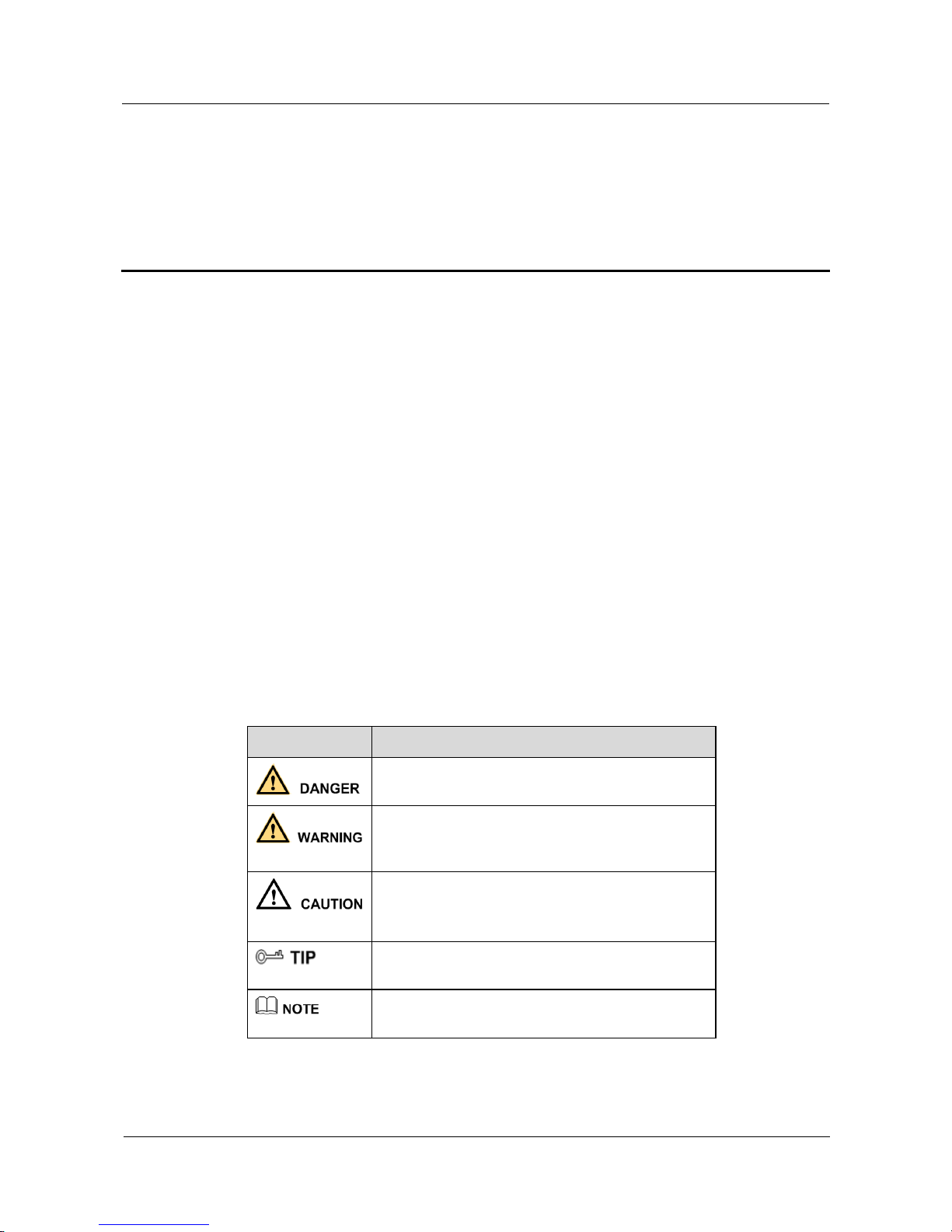
The symbols that may be found in this document are defined as follows.
Symbol
Description
Indicates a hazard with a high level of risk, which if
not avoided, will result in death or serious injury.
Indicates a hazard with a medium or low level of
risk, which if not avoided, could result in minor or
moderate injury.
Indicates a potentially hazardous situation, which if
not avoided, could result in equipment damage, data
loss, performance degradation, or unexpected results.
Indicates a tip that may help you solve a problem or
save time.
Provides additional information to emphasize or
supplement important points of the main text.
Page 4

S1700 Managed Series Ethernet Switches
Web User Manual
About This Document
Issue 05 (2012-10-25)
Huawei Proprietary and Confidential
Copyright © Huawei Technologies Co., Ltd.
iii
Change History
Changes between document issues are cumulative. Therefore, the latest document issue
contains all changes made in previous issues.
Issue 05 (2012-10-25)
Compare to Issue 04 (2012-07-25)
Optimize the content of version 04.
Issue 04 (2012-07-25)
Compare to Issue 03 (2012-05-24)
S1700 factory default username is admin and password is Admin@123
Specify the user password in range of 6~16 characters. The system
Issue 03 (2012-05-24)
Compare to Issue 02 (2012-04-26):
Enter the contact person or organization of the management switch
Issue 02(2012-04-26)
Compare to Issue 01 (2012-03-05)
5.5.3 Figure 5-28
Issue 01(2012-03-05)
Initial release.
Page 5

S1700 Managed Series Ethernet Switches
Web User Manual
Contents
Issue 05 (2012-10-25)
Huawei Proprietary and Confidential
Copyright © Huawei Technologies Co., Ltd.
iv
Contents
About This Document .................................................................................................................... ii
1 Client Setting ................................................................................................................................. 1
1.1 Logon Web Network Management Client ........................................................................................................ 1
1.1.1 Background Information ......................................................................................................................... 1
1.1.2 Operation Steps ....................................................................................................................................... 1
1.2 Know About Client Interface ........................................................................................................................... 2
1.2.1 Client Interface Components................................................................................................................... 2
1.2.2 Navigation Tree ....................................................................................................................................... 3
1.2.3 Common Buttons .................................................................................................................................... 6
1.2.4 Common Interface Elements ................................................................................................................... 7
1.3 User Timeout Processing .................................................................................................................................. 7
1.4 Configuration Saving ....................................................................................................................................... 8
1.5 Logout Web Network Management Client ....................................................................................................... 8
2 Device Summary ........................................................................................................................... 9
2.1 Device Panel..................................................................................................................................................... 9
2.2 Device Information ........................................................................................................................................ 10
2.3 Device Status .................................................................................................................................................. 10
3 System Management .................................................................................................................. 11
3.1 Reset Factory .................................................................................................................................................. 11
3.2 Reboot ............................................................................................................................................................ 12
3.3 Software Upgrade ........................................................................................................................................... 13
3.4 File System Management ............................................................................................................................... 14
3.5 System Configuration ..................................................................................................................................... 15
3.6 SNTP .............................................................................................................................................................. 16
3.7 IP Management .............................................................................................................................................. 17
3.7.1 Management VLAN .............................................................................................................................. 17
3.7.2 IPv4 ....................................................................................................................................................... 18
3.7.3 IPv6 ....................................................................................................................................................... 20
3.8 ARP ................................................................................................................................................................ 21
3.8.1 Static ARP ............................................................................................................................................. 21
3.8.2 Dynamic ARP ................................................................ ................................................................ ....... 22
3.9 IPv6 Neighbor ................................................................................................................................ ................ 22
Page 6

S1700 Managed Series Ethernet Switches
Web User Manual
Contents
Issue 05 (2012-10-25)
Huawei Proprietary and Confidential
Copyright © Huawei Technologies Co., Ltd.
v
3.9.1 Static Neighbor ..................................................................................................................................... 22
3.9.2 Dynamic Neighbor ................................................................................................................................ 23
3.9.3 Router Advertise ................................................................................................................................... 24
4 Interface Management ............................................................................................................... 26
4.1 Ethernet Interface ........................................................................................................................................... 26
4.1.1 Basic Attributes ..................................................................................................................................... 26
4.1.2 Statistics on Interface ............................................................................................................................ 28
4.2 Eth-Trunk ....................................................................................................................................................... 30
4.2.1 System Priority Configuration .............................................................................................................. 31
4.2.2 Trunk Configuration .............................................................................................................................. 32
5 Service Management .................................................................................................................. 36
5.1 VLAN ............................................................................................................................................................. 36
5.1.1 VLAN ................................................................................................................................................... 36
5.1.2 Interface ................................................................................................................................................ 38
5.2 MAC VLAN ................................................................................................................................................... 40
5.2.1 MAC VLAN ......................................................................................................................................... 41
5.2.2 Interface ................................................................................................................................................ 42
5.3 Voice VLAN ................................................................................................................................................... 43
5.3.1 Global Parameter Configuration ........................................................................................................... 44
5.3.2 Interface ................................................................................................................................................ 45
5.3.3 Voice VLAN OUI ................................................................................................................................. 46
5.3.4 Voice VLAN Device ............................................................................................................................. 47
5.3.5 LLDP-MED Voice Device .................................................................................................................... 48
5.3.6 Legacy Device ...................................................................................................................................... 49
5.4 MAC............................................................................................................................................................... 49
5.4.1 MAC Address Table .............................................................................................................................. 49
5.4.2 MAC Aging Time ................................................................................................................................. 50
5.4.3 Static MAC Table .................................................................................................................................. 51
5.4.4 Blackhole MAC Table ........................................................................................................................... 52
5.4.5 MAC Filter ............................................................................................................................................ 54
5.4.6 Migrate MAC Table .............................................................................................................................. 54
5.5 STP ................................................................................................................................................................. 55
5.5.1 STP Information .................................................................................................................................... 55
5.5.2 STP Global ............................................................................................................................................ 57
5.5.3 STP Interface ......................................................................................................................................... 60
5.5.4 MSTP Region ........................................................................................................................................ 66
5.6 IGMP Snooping .............................................................................................................................................. 68
5.6.1 Global .................................................................................................................................................... 68
5.6.2 VLAN Parameter .................................................................................................................................. 70
5.6.3 Group Deny ........................................................................................................................................... 73
5.6.4 Group Policy ......................................................................................................................................... 74
Page 7

S1700 Managed Series Ethernet Switches
Web User Manual
Contents
Issue 05 (2012-10-25)
Huawei Proprietary and Confidential
Copyright © Huawei Technologies Co., Ltd.
vi
5.6.5 Static Groups ......................................................................................................................................... 76
5.6.6 Groups ................................................................................................................................................... 78
5.6.7 Querier .................................................................................................................................................. 78
5.6.8 Mrouter ................................................................................................................................................. 79
5.6.9 Forwarding Table .................................................................................................................................. 80
6 ACL Configuration ..................................................................................................................... 82
6.1 Effective Period .............................................................................................................................................. 82
6.2 ACL Profile .................................................................................................................................................... 84
6.3 ACL Application ............................................................................................................................................ 93
6.3.1 Interface Application ............................................................................................................................. 93
6.3.2 VLAN Application ................................................................................................................................ 94
6.4 HTTP ACL ..................................................................................................................................................... 96
7 QoS Configuration ...................................................................................................................... 98
7.1 QoS Interface ................................................................................................................................................. 98
7.2 CoS Mapping ............................................................................................................................................... 100
7.3 DSCP Mapping ............................................................................................................................................ 100
7.4 IP Precedence Mapping ................................................................................................................................ 101
7.5 Service Level Mapping ................................................................................................................................ 102
7.6 QoS Scheduler .............................................................................................................................................. 102
7.7 Simple Random Early Detection .................................................................................................................. 103
7.7.1 SERD Profile ...................................................................................................................................... 103
7.7.2 SRED Information .............................................................................................................................. 105
7.7.3 SRED Drop Counter ........................................................................................................................... 106
7.8 Traffic Management ..................................................................................................................................... 107
7.8.1 Traffic Classifier ................................................................................................................................. 107
7.8.2 Traffic Behavior .................................................................................................................................. 109
7.8.3 Traffic Policy ...................................................................................................................................... 111
7.8.4 Apply Traffic Policy ............................................................................................................................ 112
7.9 Traffic Shaping ............................................................................................................................................. 113
8 IP Routing ................................................................................................................................... 115
8.1 IPv4 Route .................................................................................................................................................... 115
8.1.1 IPv4 Route Table ................................................................................................................................. 115
8.1.2 IPv4 Static/Default Route Configure .................................................................................................. 116
8.2 IPv6 Route .................................................................................................................................................... 117
8.2.1 IPv6 Route Table ................................................................................................................................. 117
8.2.2 IPv6 Static/Default Route Configure .................................................................................................. 117
9 Security........................................................................................................................................ 119
9.1 User Management ........................................................................................................................................ 119
9.1.1 User Management ............................................................................................................................... 119
9.1.2 Online User ......................................................................................................................................... 122
Page 8

S1700 Managed Series Ethernet Switches
Web User Manual
Contents
Issue 05 (2012-10-25)
Huawei Proprietary and Confidential
Copyright © Huawei Technologies Co., Ltd.
vii
9.2 802.1X .......................................................................................................................................................... 123
9.2.1 Global .................................................................................................................................................. 124
9.2.2 Mode ................................................................................................................................................... 125
9.2.3 Interface .............................................................................................................................................. 126
9.2.4 Authorized Status ................................................................................................................................ 128
9.2.5 Statistics .............................................................................................................................................. 129
9.2.6 Session ................................................................................................................................................ 130
9.2.7 Diagnostics .......................................................................................................................................... 131
9.3 Guest VLAN ................................................................................................................................................ 133
9.4 Storm Suppression........................................................................................................................................ 134
9.4.1 Storm Control ...................................................................................................................................... 134
9.4.2 Storm Suppression .............................................................................................................................. 136
9.5 Port Security ................................................................................................................................................. 137
9.5.1 Port Security Parameter Configuration ............................................................................................... 138
9.5.2 Port Security Address Information ...................................................................................................... 140
9.5.3 Address Table Import and Export ........................................................................................................ 142
9.6 MAC-based Access Control ......................................................................................................................... 143
9.6.1 Global .................................................................................................................................................. 143
9.6.2 Interface .............................................................................................................................................. 144
9.6.3 MAC-based Access Control Auth-info ............................................................................................... 145
9.6.4 MAC Format Configure ...................................................................................................................... 146
9.7 Attack Prevent .............................................................................................................................................. 147
9.7.1 Worm Prevent ..................................................................................................................................... 147
9.7.2 DoS Attack Prevent ............................................................................................................................. 148
9.8 DHCP Snooping ........................................................................................................................................... 148
9.8.1 Global .................................................................................................................................................. 149
9.8.2 Interface State Settings ........................................................................................................................ 149
9.8.3 Interface Trust Settings ....................................................................................................................... 150
9.8.4 Interface Parameter Settings ............................................................................................................... 151
9.8.5 Binding Table Information .................................................................................................................. 153
9.9 IPSG ............................................................................................................................................................. 154
9.9.1 IPSG Settings ...................................................................................................................................... 154
9.9.2 Static Binding Table ............................................................................................................................ 156
9.9.3 One Key Bind ..................................................................................................................................... 157
9.10 DAI............................................................................................................................................................. 158
9.10.1 Global ................................................................................................................................................ 158
9.10.2 Interface ............................................................................................................................................ 159
9.11 MAC Attack ............................................................................................................................................... 161
9.11.1 Illegal Packet Settings ....................................................................................................................... 161
9.12 Interface Isolation ....................................................................................................................................... 162
9.12.1 Two-way Isolation ............................................................................................................................. 162
9.12.2 One-way Isolation ............................................................................................................................. 163
Page 9

S1700 Managed Series Ethernet Switches
Web User Manual
Contents
Issue 05 (2012-10-25)
Huawei Proprietary and Confidential
Copyright © Huawei Technologies Co., Ltd.
viii
9.13 AAA ........................................................................................................................................................... 164
9.13.1 AAA Global Settings ......................................................................................................................... 164
9.13.2 Authentication Settings ..................................................................................................................... 165
9.13.3 Accounting Settings .......................................................................................................................... 167
9.14 RADIUS ..................................................................................................................................................... 168
9.14.1 RADIUS Global Settings .................................................................................................................. 168
9.14.2 RADIUS Server Settings .................................................................................................................. 170
9.14.3 RADIUS Group Server Settings ....................................................................................................... 171
9.14.4 RADIUS-server Authorization Settings ............................................................................................ 172
9.14.5 RADIUS Statistic .............................................................................................................................. 173
9.15 SSL Settings ............................................................................................................................................... 173
10 Network .................................................................................................................................... 175
10.1 SNMP ......................................................................................................................................................... 175
10.1.1 SNMP Global Settings ...................................................................................................................... 176
10.1.2 View .................................................................................................................................................. 177
10.1.3 SNMP Community ............................................................................................................................ 178
10.1.4 SNMP Host ....................................................................................................................................... 179
10.1.5 SNMP Group ..................................................................................................................................... 181
10.1.6 SNMP User ....................................................................................................................................... 183
10.1.7 SNMP Trap Settings .......................................................................................................................... 185
10.2 RMON ........................................................................................................................................................ 186
10.2.1 Statistic .............................................................................................................................................. 187
10.2.2 History .............................................................................................................................................. 188
10.2.3 Alarm ................................................................................................................................................ 190
10.2.4 Event ................................................................................................................................................. 192
10.3 LLDP .......................................................................................................................................................... 193
10.3.1 Global ................................................................................................................................................ 193
10.3.2 Port Settings ...................................................................................................................................... 194
10.3.3 Address Management ........................................................................................................................ 196
10.3.4 The Basis of TLVs ............................................................................................................................. 196
10.3.5 Dot1 TLVs ......................................................................................................................................... 197
10.3.6 Dot3 TLVs ......................................................................................................................................... 199
10.3.7 System Statistics ............................................................................................................................... 200
10.3.8 Local ................................................................................................................................................. 201
10.3.9 Remote .............................................................................................................................................. 202
10.4 LLDP-MED................................................................................................................................................ 203
10.4.1 Global Configuration ........................................................................................................................ 203
10.4.2 Interface ............................................................................................................................................ 204
10.4.3 Local ................................................................................................................................................. 205
10.4.4 Remote Interface Information ........................................................................................................... 206
11 Device Management ............................................................................................................... 207
Page 10

S1700 Managed Series Ethernet Switches
Web User Manual
Contents
Issue 05 (2012-10-25)
Huawei Proprietary and Confidential
Copyright © Huawei Technologies Co., Ltd.
ix
11.1 Device Management ................................................................................................................................... 207
11.1.1 Board Status ...................................................................................................................................... 207
11.1.2 E-label ............................................................................................................................................... 208
11.2 Device Diagnostics ..................................................................................................................................... 208
11.2.1 Interface Loopback Test .................................................................................................................... 208
11.2.2 VCT Cable Diagnostics ..................................................................................................................... 209
11.3 DDM .......................................................................................................................................................... 210
11.4 Information Center ................................................................................................................................ ..... 210
11.4.1 Parameter Settings ............................................................................................................................. 210
11.4.2 Log Information ................................................................................................................................ 212
11.5 Power Saving Management ........................................................................................................................ 213
11.6 Interface Mirror .......................................................................................................................................... 213
11.7 Tools ........................................................................................................................................................... 215
11.7.1 Ping Test ............................................................................................................................................ 215
11.7.2 Tracert ............................................................................................................................................... 216
11.7.3 One Key Information ........................................................................................................................ 217
12 Save Running-config .............................................................................................................. 218
Page 11

S1700 Managed Series Ethernet Switches
Web User Manual
1 Client Setting
Issue 05 (2012-10-25)
Huawei Proprietary and Confidential
Copyright © Huawei Technologies Co., Ltd.
1
1 Client Setting
About This Chapter
Intuitive maintenance and configuration of device can be implemented with graphical
interface through logon of Web network management client. To know about the operation and
function of this client quickly,, this chapter gives a brief introduction of basic operating
knowledge of the Web network management client.
1.1 Logon Web Network Management Client
1.2 Know About Client Interface
1.3 User Timeout Processing
1.4 Configuration Saving
1.5 Logout Web Network Management Client
1.1 Logon Web Network Management Client
A logon is necessary for user to perform corresponding configuration of switch.
1.1.1 Background Information
Web network management client can access switch by HTTP. Web network management
client should support browsers after the versions of IE6.0, Firefox 3.5.6 and Google Chrome.
This manual describes with IE8.0.
1.1.2 Operation Steps
Step 1 Open IE browser.
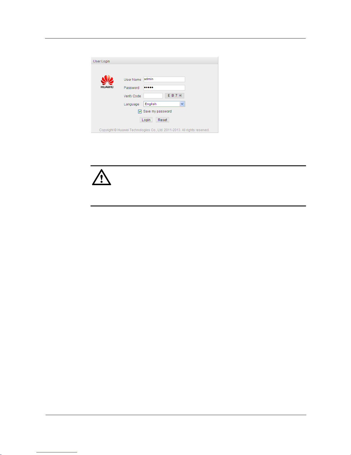
Step 2 Input address field with default URL (Universal Resource Locator) address of Web network
management client: 192.168.1.253, then press Enter key after which logon dialog box appears
on screen, configuration page being as follows:
Page 12
S1700 Managed Series Ethernet Switches
Web User Manual
1 Client Setting
Issue 05 (2012-10-25)
Huawei Proprietary and Confidential
Copyright © Huawei Technologies Co., Ltd.
2
Figure 1-1 Logon Dialog Box
Step 3 Enter Username, Password and Identifying Code into Logon Dialog Box, then click Logon
button.
CAUTION
S1700 factory default username is admin and password is [email protected] can modify the
password. Please refer to the description in Security> User Management
Step 4 After successful logon of Web network management system, home page of system appears.
Please refer to Figure 1-2 for introduction of home page.
----End
1.2 Know About Client Interface
Knowing about the client interface is helpful to quickly find operator site, thus improve
operating efficiency.
1.2.1 Client Interface Components
Layout of typical operating interface of Web network management client is described.
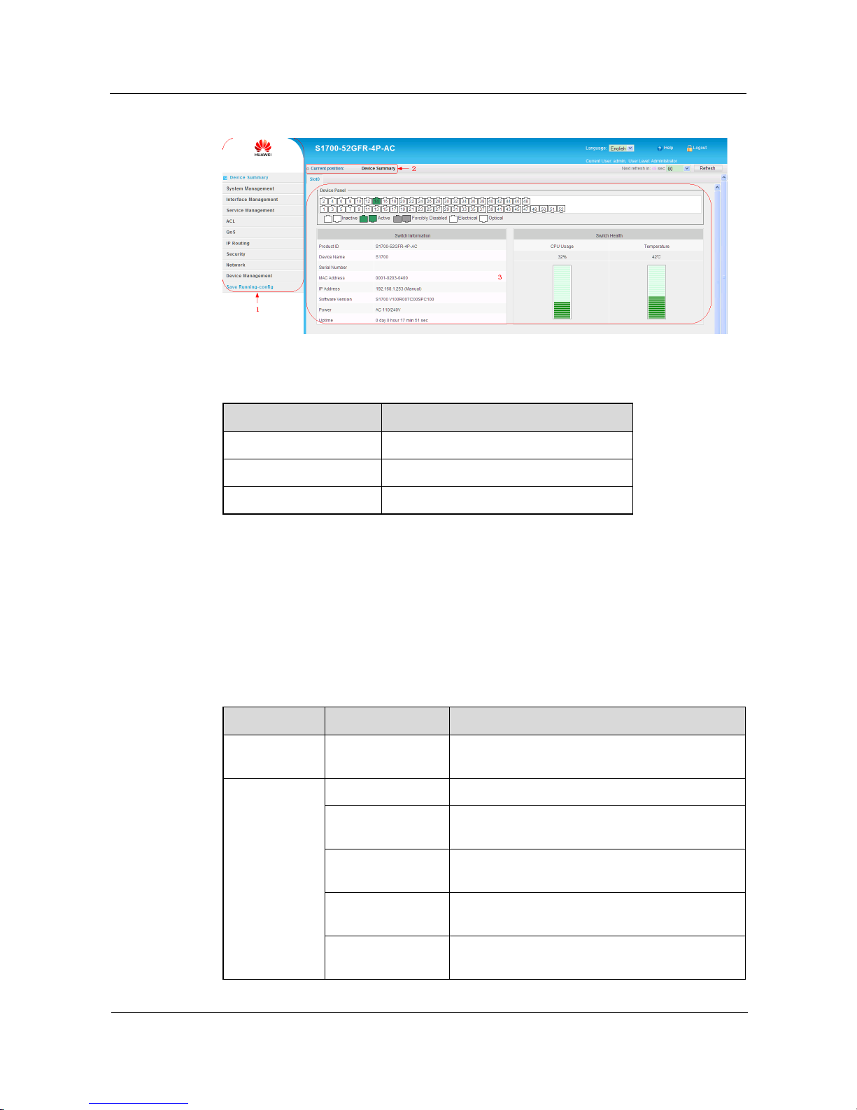
The typical operating interface of Web network management is as shown in Fig.1-2
Page 13
S1700 Managed Series Ethernet Switches
Web User Manual
1 Client Setting
Issue 05 (2012-10-25)
Huawei Proprietary and Confidential
Copyright © Huawei Technologies Co., Ltd.
3
Figure 1-2 Device Summary
Table 1-1 Device Summary Description
Title
Description
1
Navigation area
2
Current page
3
Operating area
1.2.2 Navigation Tree
The menu consists of following 11 items: Device Summary, System Management, Interface
Management, Service Management, ACL, QoS, IP Routing, Security, Network, Device
Management and Save Running-config.
Each item comprises submenu, as shown in Figure 1-2
Table 1-2 Description of Web Network Management Menu Items
Menu
Sub-Menu
Description
Device
Summary
Device Summary
Show front panel mimetic diagram, information
and status of device.
System
Management
Reset Factory
Reset setting of switch to factory default.
Reboot
Reboot switch with specified version of software
and configuration files.
Software Upgrade
Upgrade firmware version of switch in HTTP or
FTP mode.
File System
Management
Upload, download and delete files of device
FLASH.
System
Configuration
Set device name and connection timeout duration.
Page 14

S1700 Managed Series Ethernet Switches
Web User Manual
1 Client Setting
Issue 05 (2012-10-25)
Huawei Proprietary and Confidential
Copyright © Huawei Technologies Co., Ltd.
4
Menu
Sub-Menu
Description
SNTP
SNTP Server Configuration:set SNTP server parameters.
Time configuration: manually configure time for system
clock.
IP Management
View and manage VLAN, local management of
IPv4 and IPv6 addresses.
ARP
Perform ARP configuration.
IPv6 Neighbor
Configure static neighbor table, view dynamic
neighbor table, configure and view router
advertise.
Interface
Management
Ethernet Interface
Base attribute of interface: display the connection status, to
configure relevant parameters for individual interface or a
group of interfaces.
Interface traffic statistic: display traffic statistic information
of each interface.
Eth-Trunk
Priority: configure system priority.
Traffic sharing mode: configure traffic sharing mode.
Trunk: view and configure Trunk.
Trunk ID member peer-to-peer information: check Trunk
member information.
Service
Management
VLAN
Create, delete and edit VLAN, edit/display
members based on VLAN, and edit members
according to interface/interface range.
MAC VLAN
Create and delete MAC VLAN, display MAC
VLAN list based on VLAN or MAC address, and
enable/disable MAC VLAN according to
interface/interface range.
Voice VLAN
Perform Voice VLAN relevant configuration
MAC
MAC address list information: display/clear dynamic MAC
address.
MAC ageing time: configure MAC address ageing time.
Static MAC configuration: create/delete static MAC
address.
Black hole MAC configuration: create/delete static black
hole MAC address.
MAC filter configuration: enable/disable MAC filter at
specified interface.
Address list information migration: display MAC address
migration information.
STP
Relevant parameters of spanning tree can be
configured in overall mode and based on interfaces.
IGMP Snooping
Implement following configuration management:
global parameter, VLAN parameter, interface
learning, multicast group policy, static multicast
group, multicast group, querier, routing interface
and forwarding list.
ACL
Effective Period
Configure effective period of applying ACL rules.
ACL Profile
Create AC rules.
ACL Application
Apply rules to specified interface or VLAN.
Page 15

S1700 Managed Series Ethernet Switches
Web User Manual
1 Client Setting
Issue 05 (2012-10-25)
Huawei Proprietary and Confidential
Copyright © Huawei Technologies Co., Ltd.
5
Menu
Sub-Menu
Description
HTTP ACL
Apply rules to HTTP protocol data of accessing
switch.
QoS
QoS Interface
Configure trust model and default CoS value of
specified interface.
CoS Mapping
Perform mapping to CoS value and service grade.
DSCP Mapping
Perform mapping to DSCP value and service grade.
IP Precedence
Mapping
Perform mapping to IP Precedence value and
service grade.
Service Level
Mapping
Map different service grades to hardware queue of
switch.
QoS Scheduler
Configure QoS scheduling method and WRR
weighted value.
SRED
Configure SRED.
Traffic
Management
Create different classes of flows to control network
traffic.
Traffic Shaping
Control the maximal transmission rate of interface,
and limit the output traffic of network.
IP Routing
IPv4 Route
Add and check static IPv4 routing.
IPv6 Route
Add and check static IPv6 routing.
Security
User Management
Perform user account relevant configuration
802.1X
Perform 802.1X relevant configuration
Guest VLAN
Configure Guest VLAN.
Storm Suppression
Perform the relevant configuration of storm control
and suppression.
Port Security
Control network access.
MAC-based Access
Control
Authenticate MAC address of device to achieve
authentication access.
Attack Prevent
Configure anti-attack settings.
DHCP Snooping
Perform DHCP Snooping configuration.
IPSG
Perform IP source protection configuration.
DAI
Perform dynamic address detection configuration.
MAC Attack
Perform illegal message and MAC spoofing
configurations.
Interface Isolation
Perform interface isolation configuration
Page 16

S1700 Managed Series Ethernet Switches
Web User Manual
1 Client Setting
Issue 05 (2012-10-25)
Huawei Proprietary and Confidential
Copyright © Huawei Technologies Co., Ltd.
6
Menu
Sub-Menu
Description
AAA
Perform configuration of system authentication and
charging.
RADIUS
Configure RADIUS server relevant parameters.
SSL Settings
Perform SSL configuration.
Network
SNMP
Perform SNMP parameters relevant configuration.
RMON
Perform RMON parameters relevant configuration.
LLDP
Perform LLDP configuration management.
LLDP-MED
Perform LLDP-MED configuration management.
Device
Management
Device
Management
View hardware information of device, used for
confirming whether system is at normal state or not
when the product of Huawei leaves factory, to
guarantee the versions programmed by all products
through strict inspection of Huawei are proper.
Device Diagnostics
Interface loopback diagnostics: perform loopback
diagnostics to specified interface.
VCT cable diagnostics: perform diagnostics to specified
cable to detect cable faults.
DDM
Check parameters of optical interface.
Information Center
Perform configuration management of system log.
Power Saving
Management
Enable or disable power saving management and
EEE functions.
Interface Mirror
Add mirroring source and objective interfaces, and
display the configured mirroring session.
Tools
Ping test: perform Ping test.
Tracert: perform routing test.
One key information: one key download of configuration,
log and error information.
Save
Running-config
Save
Running-config
Save the modified parameters.
1.2.3 Common Buttons
Knowing about following introduction of common buttons can make user convenient to
operate Web management system.
Functions of common buttons are shown as follows.
Table 1-3 Function Description of Common Buttons
Button
Description
Apply
Submit input information and confirm current
information provided by system.
Page 17
S1700 Managed Series Ethernet Switches
Web User Manual
1 Client Setting
Issue 05 (2012-10-25)
Huawei Proprietary and Confidential
Copyright © Huawei Technologies Co., Ltd.
7
Button
Description
Create
Create an entry of certain function.
Configure
Click to configure relevant functions.
Query
Data query based on given conditions.
Delete
Delete current selected data.
Reboot
Click to reboot switch.
Clear
Click to clear statistic data on webpage.
Refresh
Click to refresh statistic data on webpage.
1.2.4 Common Interface Elements
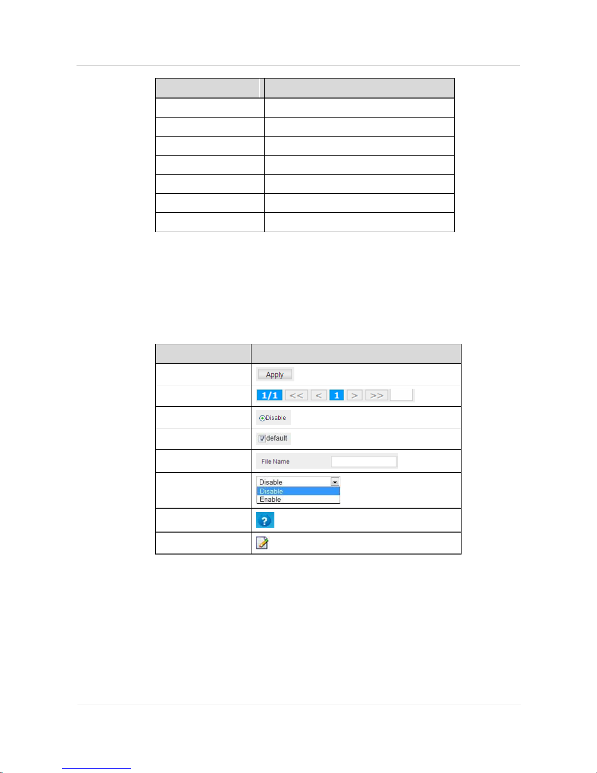
Common interface elements of Web network management client are introduced.
Common interface elements are shown as follows.
Table 1-4 Description of Common Interface Elements
Name
Interface Elements
Button
Page Selection Button
Radio Button
Check Box
Textbox
Pull-down Menu
Help
Edit
1.3 User Timeout Processing
If the Web network management webpage is unused by user for a certain time and then this
timeout webpage is clicked again, system will log off because of timeout, and return to Web
logon dialog box (as shown in Figure 1-1); if necessary, please logon again to continue.
Page 18

S1700 Managed Series Ethernet Switches
Web User Manual
1 Client Setting
Issue 05 (2012-10-25)
Huawei Proprietary and Confidential
Copyright © Huawei Technologies Co., Ltd.
8
NOTE
Default timeout duration of Web page logon is 3 minutes.
1.4 Configuration Saving
When items configurations are completed, click Parameter Saving link to save configuration.
CAUTION
When items configurations of webpage are completed, configuration must be saved. If not,
parameters will be lost when webpage changes or is refreshed. When saving the configuration,
if this size of surplus memory is less than the current configuration size, the saving process
will fail. Please delete the needless file via File System Management then execute
configuration saving.
1.5 Logout Web Network Management Client
To ensure security of Web network management system, user should timely logout after
configuration.
Click button at the upper right of any webpage on Web Network Management Client
to logout.
Page 19
S1700 Managed Series Ethernet Switches
Web User Manual
2 Device Summary
Issue 05 (2012-10-25)
Huawei Proprietary and Confidential
Copyright © Huawei Technologies Co., Ltd.
9
2 Device Summary
About This Chapter
This chapter describes all components of logon homepage, including device panel, device
information and device status etc.
2.1 Device Panel
2.2 Device Information
2.3 Device Status
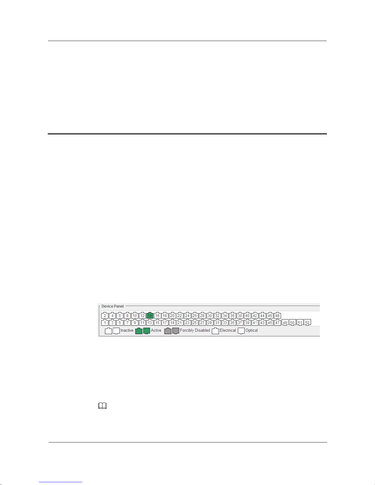
2.1 Device Panel
This panel Display its main information as shown in Figure 2-1.
Clicking Device Summary menu under navigation bar, user can view Device Panel page, the
configuration page is shown as follows.
Figure 2-1 Device Panel Webpage
Based on type of the switch connected, the display area of Web network management panel
can intuitively display information of the various interfaces of this switch, the contents
displayed including:
Interface amount.
Operating statuses of interfaces: including activated state and interface type.
NOTE
Place mouse on some interface to view number and connection rate of this interface.
Page 20
S1700 Managed Series Ethernet Switches
Web User Manual
2 Device Summary
Issue 05 (2012-10-25)
Huawei Proprietary and Confidential
Copyright © Huawei Technologies Co., Ltd.
10
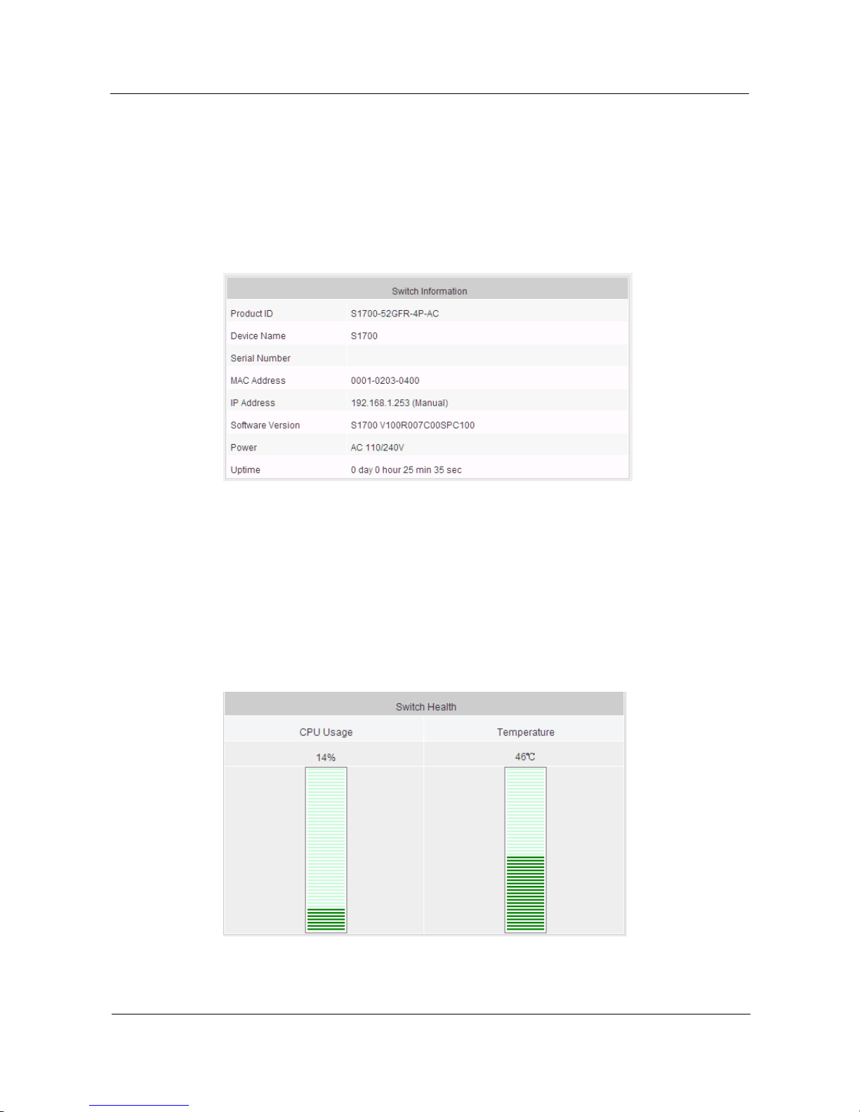
2.2 Device Information
It shows model, device name, serial number, MAC address, IP address, system software
version, power and uptime of switch.
Click Device Summary menu under navigation bar, and view the page of Device Information,
configuration page is shown as follows.
Figure 2-2 Device Information Page
2.3 Device Status
It shows current CPU usage factor and temperature information of switch.
Click Device Summary menu under navigation bar, and view the page of Device Status,
configuration page is shown as follows.
Figure 2-3 Device Status Page
Page 21
S1700 Managed Series Ethernet Switches
Web User Manual
3 System Management
S1700 Managed Series Ethernet Switches
Issue 05 (2012-10-25)
Huawei Proprietary and Confidential
Copyright © Huawei Technologies Co., Ltd.
11
3 System Management
About This Chapter
Basic management and configuration functions of switch are introduced.
3.1 Reset Factory
3.2 Reboot
3.3 Software Upgrade
3.4 File System Management
3.5 System Configuration
3.6 SNTP
3.7 IP Management
3.8 ARP
3.9 IPv6 Neighbor
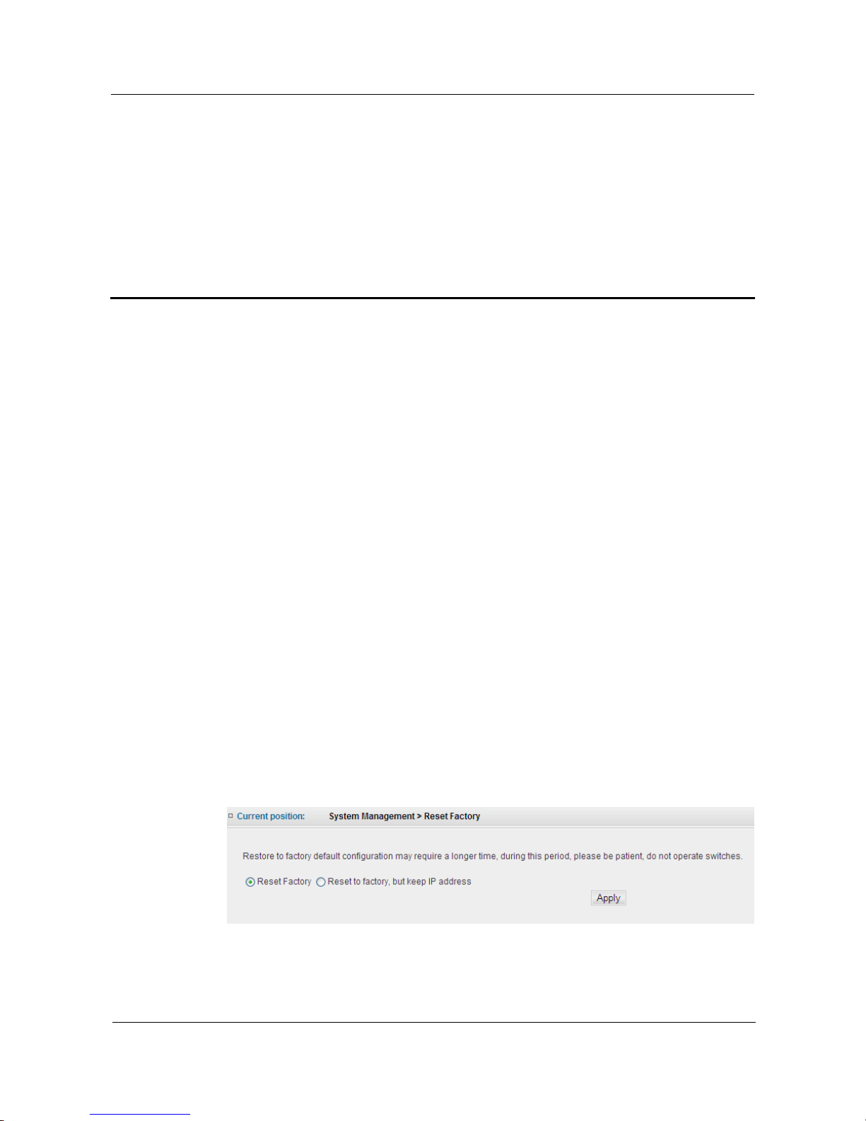
3.1 Reset Factory
Clicking System Management > Reset Factory, user can reset device to factory default
configuration through this webpage. The configuration page is shown as follows
Figure 3-1 Reset Factory
Page 22
S1700 Managed Series Ethernet Switches
Web User Manual
3 System Management
S1700 Managed Series Ethernet Switches
Issue 05 (2012-10-25)
Huawei Proprietary and Confidential
Copyright © Huawei Technologies Co., Ltd.
12
Table 3-1 Parameters of Reset Factory
Item
Description
Reset Factory
Reset switch to factory default configuration.
Reset to factory , but keep IP
address
Reset all configuration information of switch apart from
IP address.
Reset switch to factory settings
Step 1 Click System Management > Reset Factory.
Step 2 Click Reset Factory.
Step 3 Click Apply button to apply all the changes made.
----End
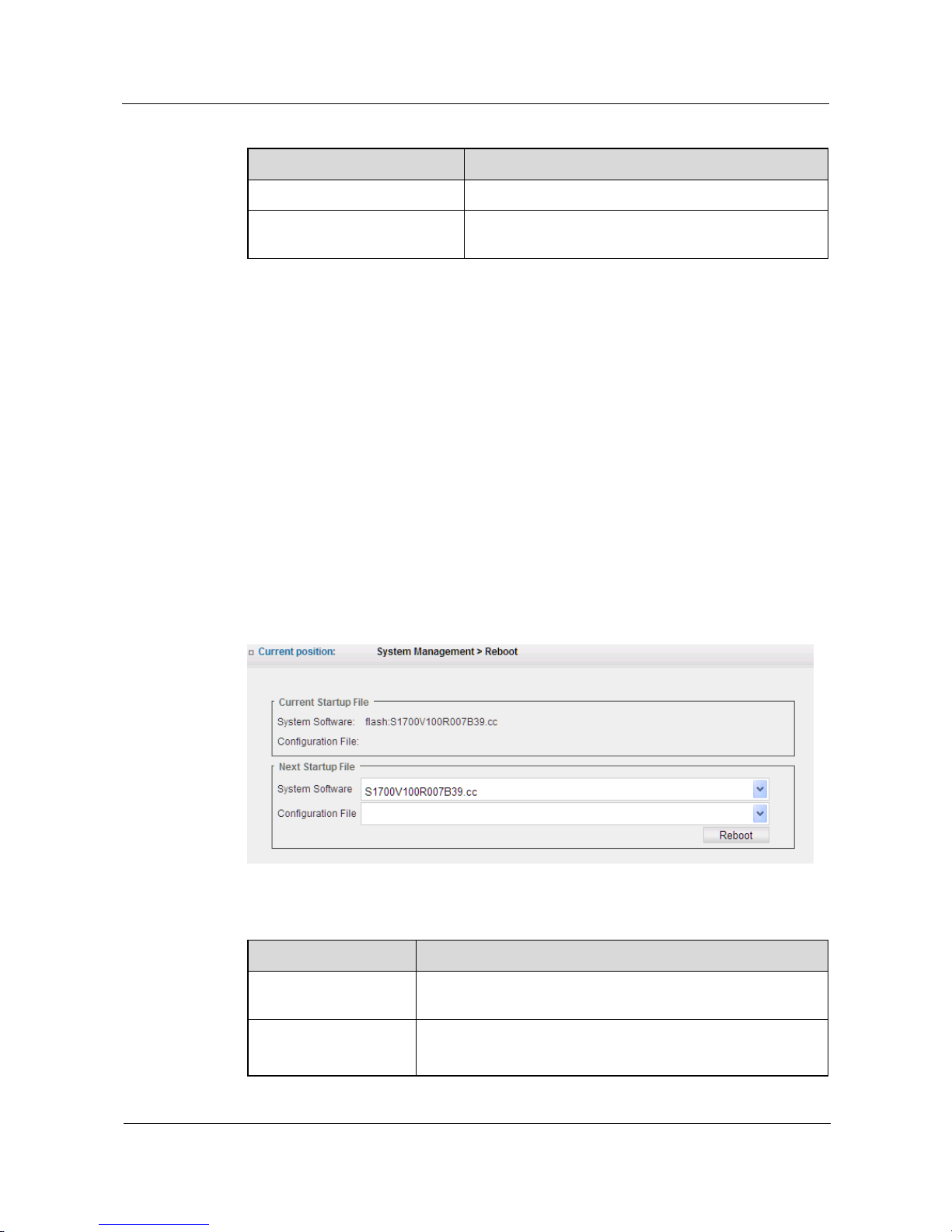
3.2 Reboot
Click System Management > Reboot to bounce a device reboot webpage. Select System
Software and Configuration File options under the Next Startup File to set this switch to start
next time, the configuration page is as shown in Figure 3-2.
Figure 3-2 Set Startup File
Table 3-2 Parameters of Reboot
Item
Description
Current Startup File
It shows the system software and configuration files currently
used by switch
Next Startup File
System Software: select firmware version of next startup.
Configuration File:select configuration file of next startup.
Page 23
S1700 Managed Series Ethernet Switches
Web User Manual
3 System Management
S1700 Managed Series Ethernet Switches
Issue 05 (2012-10-25)
Huawei Proprietary and Confidential
Copyright © Huawei Technologies Co., Ltd.
13
Assignment of Switch Startup File
Step 1 Click System Management > Device Reboot to bounce a webpage as shown in Fig.3-2.
Step 2 Select corresponding startup file in Next Startup File.
Step 3 Click Reboot button to apply all the changes made, which will take effect next startup.
----End
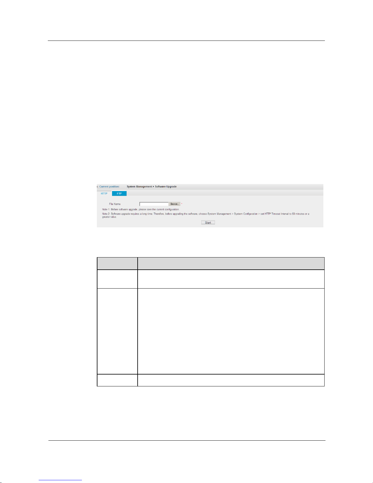
3.3 Software Upgrade
This series of switch supports software upgrade by means of HTTP and FTP.
Click System Management> Software Upgrade, to upgrade software of the switch, the
configuration page is as shown in Fig.3-3:
Figure 3-3 Software Upgrade
Table 3-3 Parameters of Software Upgrade
Item
Description
HTTP
Click Browse to choose firmware files to be upgraded, which is stored in
computer with a suffix of „.cc‟, such as S1700V100R007B39.cc.
FTP
IPv4 address: enter IPv4 address of FTP download server.
IPv6 address: or enter IPv6 address of FTP download server.
Username/password: enter username and password of FTP download
server.
TCP port: enter TCP port number of FTP download server.
File name: complete path and filename of firmware file.
Saved as: firmware file name saved on switch after upgrade without slash
(/), the first character excluding point (.), and length of filename is not
more than 64 characters (valid characters including: A-Z, a-z, 0-9, „.‟,
„-„ and „_‟.
Start
Click this button to upgrade software.
Page 24
S1700 Managed Series Ethernet Switches
Web User Manual
3 System Management
S1700 Managed Series Ethernet Switches
Issue 05 (2012-10-25)
Huawei Proprietary and Confidential
Copyright © Huawei Technologies Co., Ltd.
14
CAUTION
due to a relatively long time needed for software upgrade, please previously modify HTTP
Connection Timeout Duration of System Management > System Configuration page to 50
minutes or bigger.
Upgrade Firmware File of Switch by HTTP
Step 1 Click System Management > Software Upgrade, to bounce a webpage as shown in Fig.3-3.
Step 2 Click Browse to choose the firmware files to be upgraded.
Step 3 Click Start button to upgrade.
----End
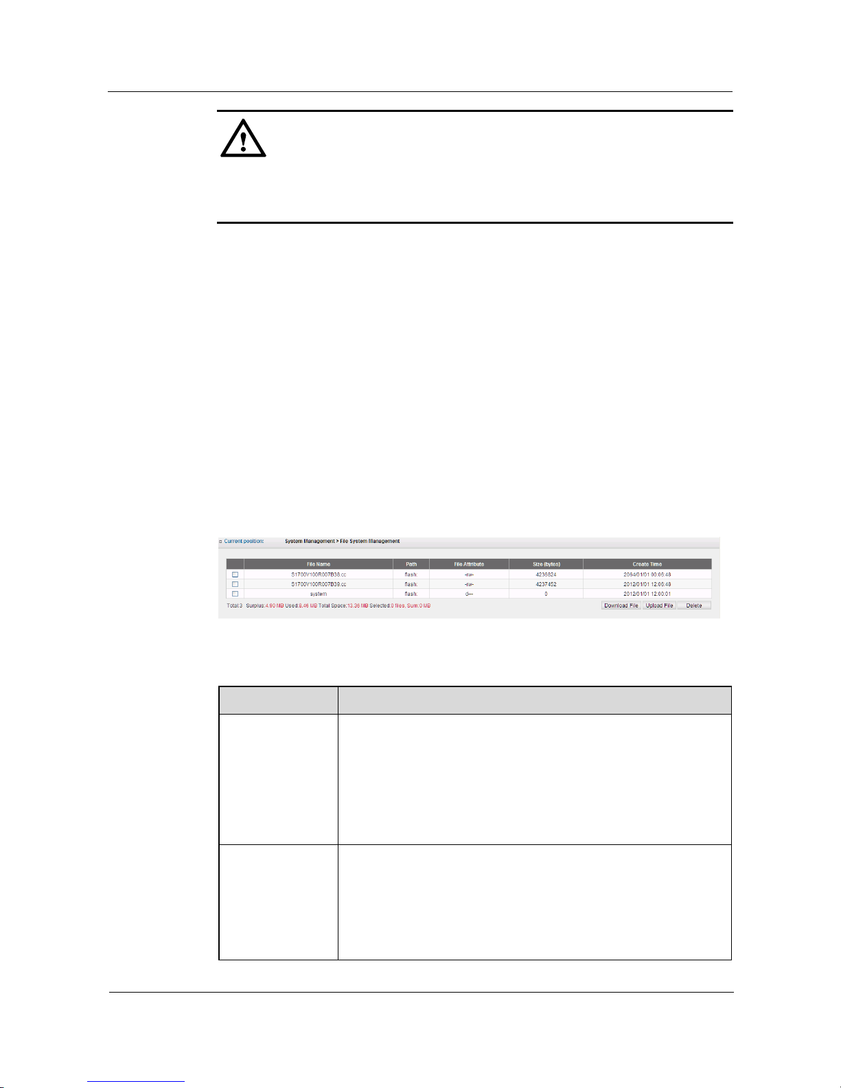
3.4 File System Management
Click System Management > File System Management to download or delete system and
configuration files of switch, or upload files to switch, the configuration page is as shown in
Figure 3-4.
Figure 3-4 File System Management
Table 3-4 Parameters of File System Management
Item
Description
File List
File list: shows all files saved on current switch.
Filename: system filename.
Path: location of system files.
File Attributes: Attributes (read/write) of system files.
Size (bytes): size of system files in bytes.
Create Time: creation time of system files.
Download File
Click this button to download files to switch.
File Name of Download: click Browse to choose the files to be
downloaded.
Save as: filename to be saved after download. The length of filename
is not more than 64 characters (illegal characters including: \, /, :,
*, ?, ", <, >, | and space.
Page 25
S1700 Managed Series Ethernet Switches
Web User Manual
3 System Management
S1700 Managed Series Ethernet Switches
Issue 05 (2012-10-25)
Huawei Proprietary and Confidential
Copyright © Huawei Technologies Co., Ltd.
15
Item
Description
Upload File
Upload the chosen files to local computer.
Delete
Delete the chosen files from switch.
CAUTION
Those specified as startup files can not be deleted.
Delete System Files of Switch
Step 1 Click System Management > File Management, the webpage as shown in Fig.3-4 appears.
Step 2 Choose system files to be deleted from list.
Step 3 Click Delete button.
----End
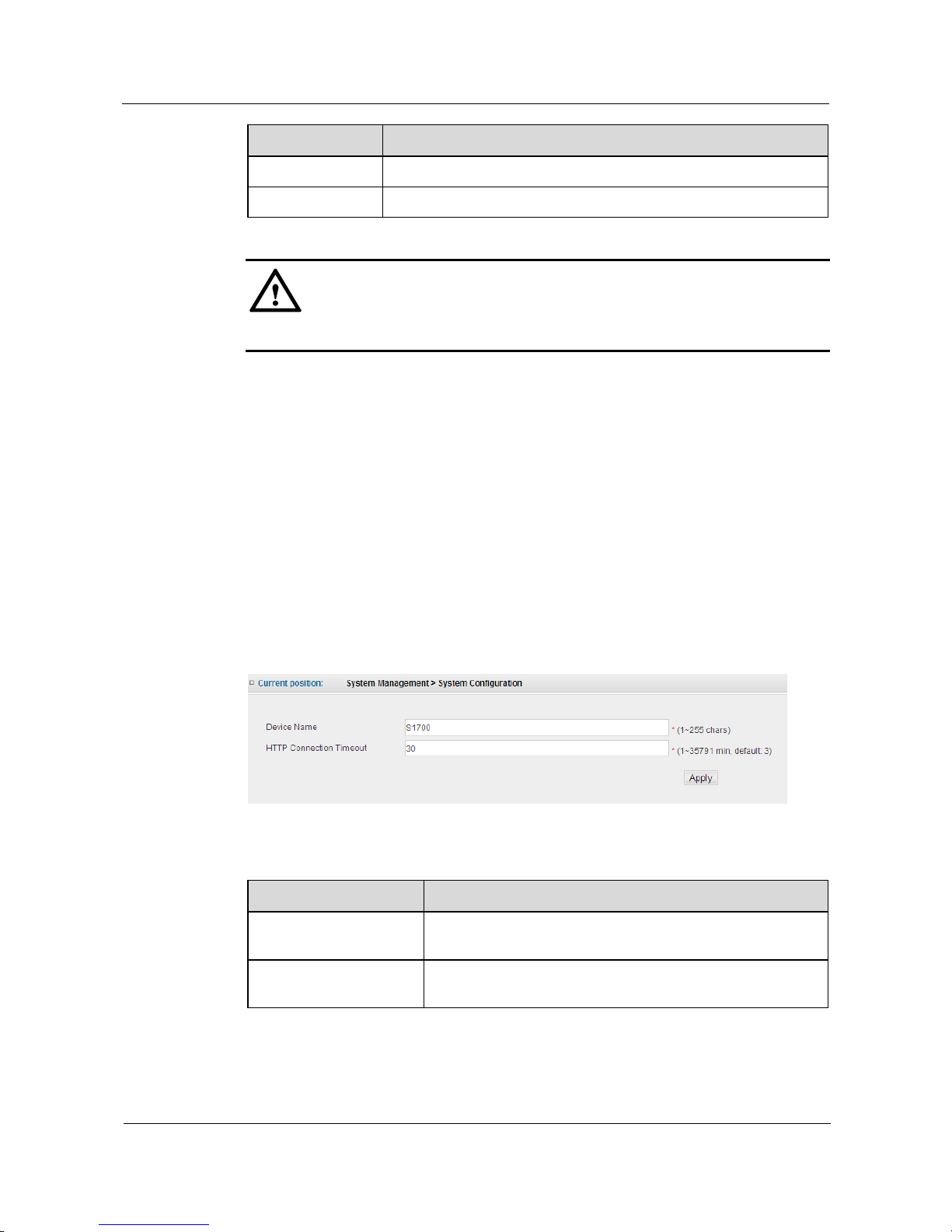
3.5 System Configuration
Click System Management > System Configuration, to set device name and HTTP connection
timeout duration of switch, the configuration page is as shown in Fig.3-5.
Figure 3-5 System Configuration
Table 3-5 Parameters of System Configuration
Item
Description
Device Name
Enter the device name of switch with a maximal length of 255
characters.
HTTP Connection
Timeout Duration
Enter the HTTP connection timeout duration of switch within
1-35791 minutes, default is 3 minutes.
Page 26
S1700 Managed Series Ethernet Switches
Web User Manual
3 System Management
S1700 Managed Series Ethernet Switches
Issue 05 (2012-10-25)
Huawei Proprietary and Confidential
Copyright © Huawei Technologies Co., Ltd.
16
Set Device Name of Switch
Step 1 Click System Management > System Configuration, to bounce a webpage as shown in Fig.3-5
Step 2 Enter the device name of switch into Device Name field.
Step 3 Click Apply button to apply all the changes made.
----End
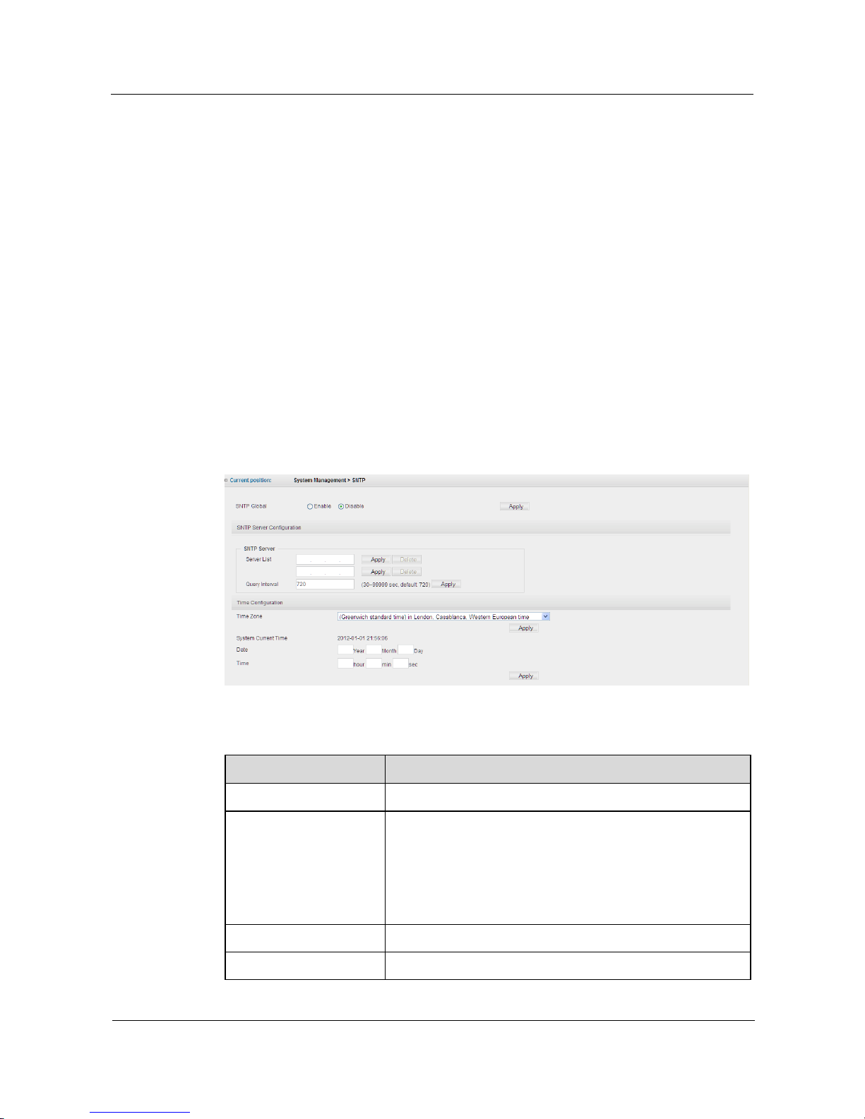
3.6 SNTP
In network, it is very important to configure time synchronization of entire network,
particularly the causality of event can be detected based on the time of log entry. SNTP
(simple network time protocol) is mainly applied to synchronizing clocks of computers in the
network.
Click System Management > SNTP, to configure the system time, the configuration page is
shown as follows.
Figure 3-6 SNTP Configuration
Table 3-6 Parameters of SNTP Configuration
Item
Description
SNTP Global
Choose to enable/disable the SNTP function.
SNTP Server
Configuration
Server List: Enter the IP addresses of the primary and
secondary SNTP server from which the switch will obtain the
time settings.
Query Interval: This is the interval between requests for
updated SNTP information. (Range: 30-99999; Default: 720
seconds)
Time Zone
Set your local time zone.
System Current Time
Display current time of switch.
Page 27
S1700 Managed Series Ethernet Switches
Web User Manual
3 System Management
S1700 Managed Series Ethernet Switches
Issue 05 (2012-10-25)
Huawei Proprietary and Confidential
Copyright © Huawei Technologies Co., Ltd.
17
Item
Description
Date
Manually set the date of switch.
Year: set the year (Range: 2010-2073).
Month: set the month. (Range: 1-12).
Day: set the day. (Range: 1-31).
Time
Manually set the time of switch.
Hour: set the hour. (Range: 0-23)
Minute: set the minute. (Range: 0-59)
Second: set the second. (Range: 0-59)
Time configuration of Switch
Step 1 Click System Management > SNTP, to bounce the webpage as shown in Fig.3-6.
Step 2 Choose Enable from SNTP Global.
Step 3 Enter a SNTP server address in Server List field, for example 192.168.22.44.
Step 4 Click Apply button of SNTP Server Configuration to apply all changes made.
----End
3.7 IP Management
S1700 series switch has only two VLAN corresponding interface anytime to configure IP
address, and this VLAN is management VLAN. If management for the switch is needed, an IP
address for VLAN interface of the switch must be configured.
3.7.1 Management VLAN
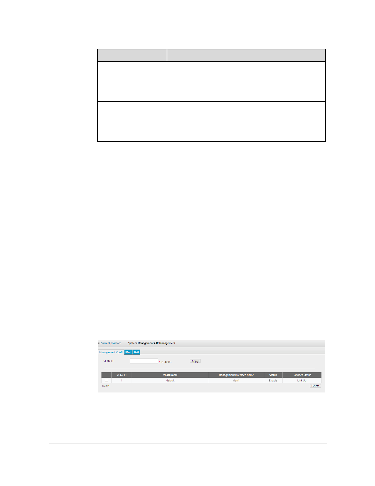
Click System Management > IP Management > Management VLAN page to configure the
management VLAN for the switch, the configuration page is shown as follows.
Figure 3-7 Management VLAN
Page 28
S1700 Managed Series Ethernet Switches
Web User Manual
3 System Management
S1700 Managed Series Ethernet Switches
Issue 05 (2012-10-25)
Huawei Proprietary and Confidential
Copyright © Huawei Technologies Co., Ltd.
18
Table 3-7 Parameters of Management VLAN
Item
Description
VLAN ID
Configure Management VLAN identifier (2-4094) (the VLAN must
be firstly created on the switch).
List
Display all management VLANs of the switch. The default
management VLAN ID is 1.
CAUTION
Default management VLAN name of switch is Default.
3.7.2 IPv4
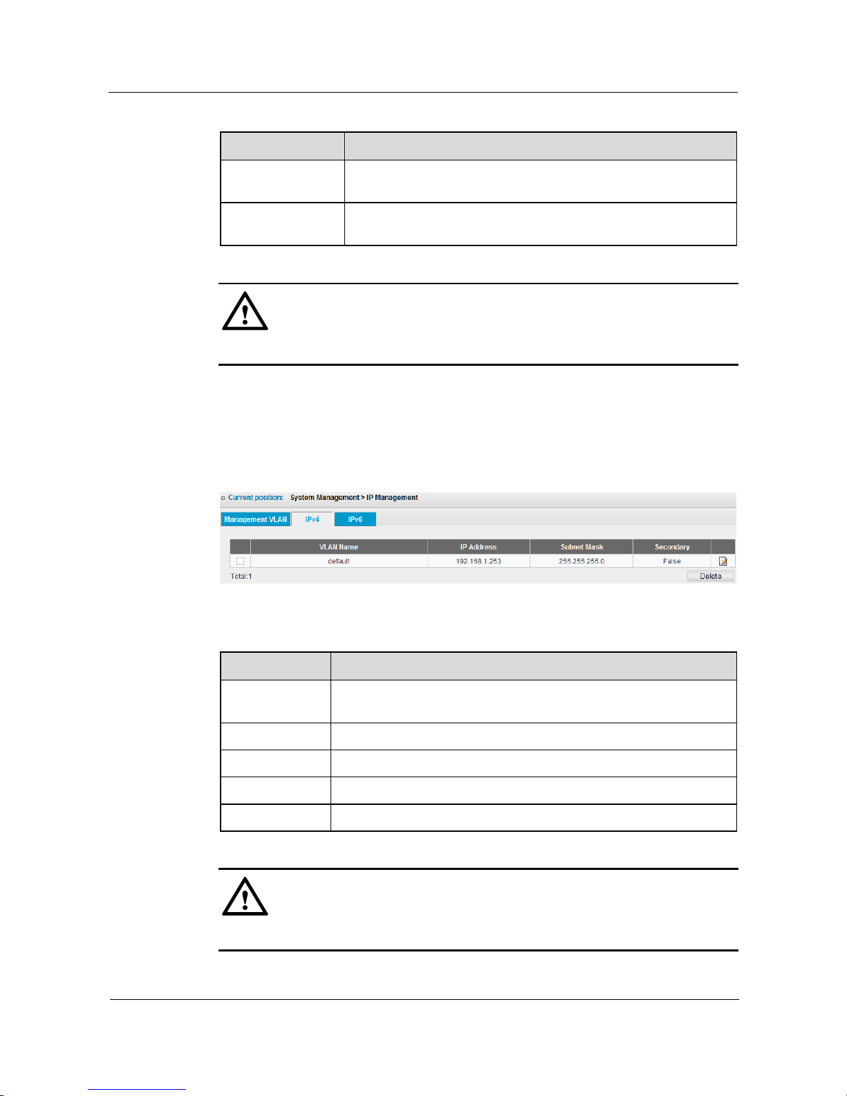
Click System Management > IP Management > IPv4 to configure an IPv4 address for the
switch, the configuration is as shown as follows.
Figure 3-8 IPv4 Address
Table 3-8 Parameters of IPv4 Address
Item
Description
List
Display the IP address of switch management VLAN. Click the Edit
icon in the right-hand column to modify the VLAN IP address.
VLAN Name
Name of the management VLAN.
IP Address
IP management addresses.
Subnet Mask
Subnet mask of IP address.
Secondary
The secondary IP address of the switch.
CAUTION
Default management VLAN of switch is Default, for example 192.168.1.253.
Page 29
S1700 Managed Series Ethernet Switches
Web User Manual
3 System Management
S1700 Managed Series Ethernet Switches
Issue 05 (2012-10-25)
Huawei Proprietary and Confidential
Copyright © Huawei Technologies Co., Ltd.
19
IPv4 Address Settings (DHCP)
Step 1 Click System Management > IP Management > IPv4 to display the page as shown in Figure
3-8.
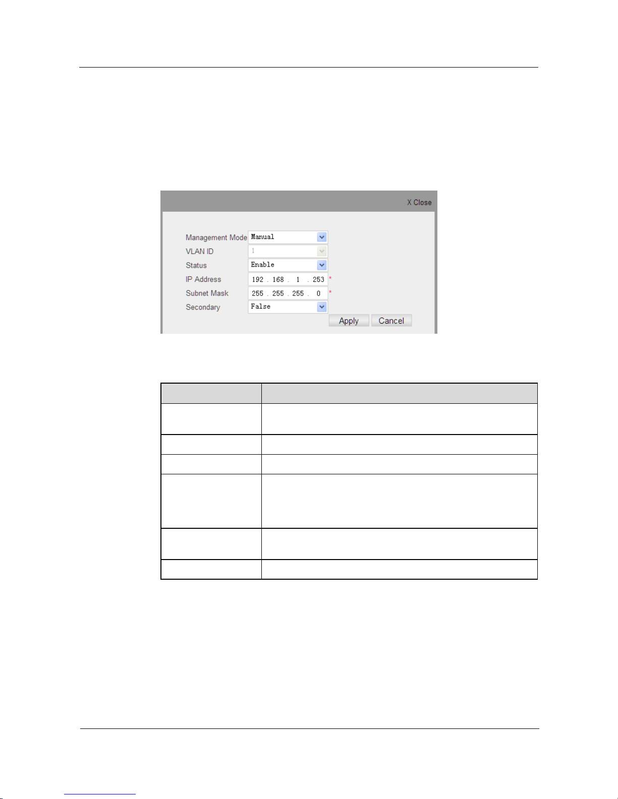
Step 2 Click the Edit icon in the right-hand column of Default item, the configuration page is shown
as follows.
Figure 3-9 IPv4 Address Settings
Table 3-9 Parameters of IPv4 Address Settings
Item
Description
Management mode
There are two ways to obtain IP address: manual configuration and
DHCP (Default: manual configuration)
VLAN ID
Select management VLAN ID from the drop-down menu.
Status
Choose to enable/disable this management interface.
IP Address
The fixed IP management address that user can manually configure
when IP address method is selected “manual”. Valid IP addresses
consist of four numbers, 0 to 255, separated by periods. (Default:
192.168.1.253)
Subnet Mask
This mask confirms the host address bits used for routing to
specific subnets. (Default: 255.255.255.0).
Secondary
The secondary IP address of the switch.
Step 3 Specified management mode is DHCP.
Step 4 Click Apply to apply all the changes made.
----End
Page 30
S1700 Managed Series Ethernet Switches
Web User Manual
3 System Management
S1700 Managed Series Ethernet Switches
Issue 05 (2012-10-25)
Huawei Proprietary and Confidential
Copyright © Huawei Technologies Co., Ltd.
20
3.7.3 IPv6
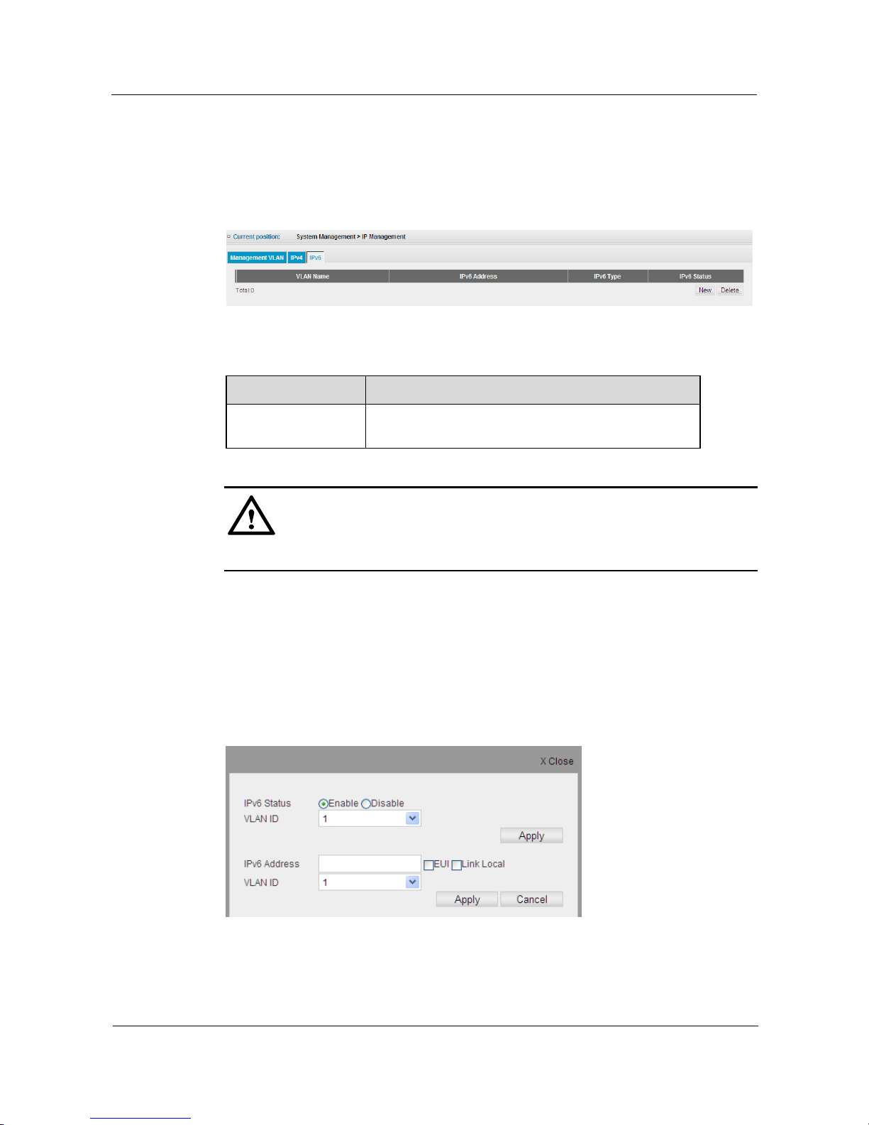
Click System Management > IP Management > IPv6 to configure an IPv6 address for the
switch, the configuration page is shown as follows.
Figure 3-10 IPv6 Address
Table 3-10 Parameters of IPv6 Address
Item
Description
List
Display the relevant IP address information of the
management VLAN.
CAUTION
Default management VLAN of switch does not enable IPv6 Address
IPv6 Address Settings
Step 1 Click System Management > IP Management > IPv6 to bounce the configuration page as
shown in Fig.3-10.
Step 2 Click New to add an IPv6 address for switch management VLAN, to bounce the
configuration page shown as follows.
Figure 3-11 IPv6 Address Settings
Page 31
S1700 Managed Series Ethernet Switches
Web User Manual
3 System Management
S1700 Managed Series Ethernet Switches
Issue 05 (2012-10-25)
Huawei Proprietary and Confidential
Copyright © Huawei Technologies Co., Ltd.
21
Table 3-11 Parameters of IPv6 Address Settings
Item
Description
IPv6 Status
Choose to enable/disable IPv6 function.
VLAN ID
Choose management VLAN ID from following menu.
IPv6 Address
Enter IPv6 address of VLAN interface.
EUI: use interface ID to automatically generate latter
64bytes.
Local Link: configure a local link address.
VLAN ID
Choose management VLAN ID from following menu.
Step 3 Enter IPv6 address of VLAN interface into IPv6 Address field.
Step 4 Click Apply button to apply all the changes made.
----End
3.8 ARP
Address Resolution Protocol (ARP) is applied to mapping an IP address to physical layer
(MAC) address. When sending an IP frame, the switch firstly inquires MAC address related to
objective IP address from ARP table. If address is found, the switch will write in this MAC
address at the specified position of frame head, and send the frame to the objective. If
corresponding MAC address is not found from ARP table, the switch will broadcast an ARP
request message to all devices of network.
When receiving this request, these devices will discard the request message if the objective IP
address of the message is different from their own IP address. If they are same, these devices
write their own MAC address to the objective address section and return this message to
source device. When receiving a return message, the source device write the objective IP
address and corresponding MAC address in ARP table, and forwards the IP traffic to the
objective device.
3.8.1 Static ARP
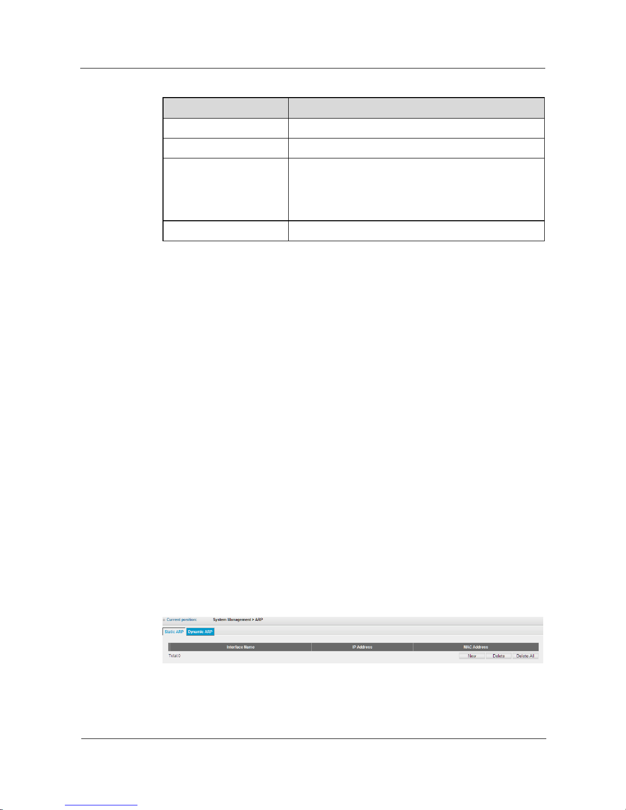
Click System Management > ARP > Static ARP page to display static entries in the ARP table,
the configuration page is shown as the figure below.
Figure 3-12 Static ARP
Page 32
S1700 Managed Series Ethernet Switches
Web User Manual
3 System Management
S1700 Managed Series Ethernet Switches
Issue 05 (2012-10-25)
Huawei Proprietary and Confidential
Copyright © Huawei Technologies Co., Ltd.
22
3.8.2 Dynamic ARP
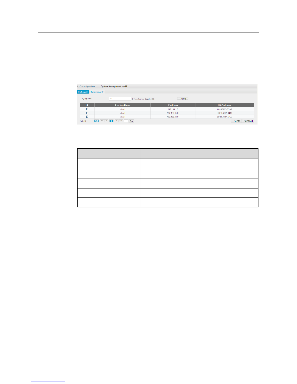
Click System Management > ARP > Dynamic ARP page to display the switch detected
dynamic ARP entries and set the aging time for ARP cache entries, the configuration page is
shown as the figure below.
Figure 3-13 Dynamic ARP
Table 3-12 Parameters of Dynamic ARP
Item
Description
Aging Time
Set the aging time for dynamic entries in the ARP table.
(Range: 0-65535 minutes; Default: 20 minutes) The ARP
aging timeout can only be set globally for all VLANs.
Interface Name
Name of the interface.
IP Address
Dynamically detected IP address.
MAC Address
Dynamically detected MAC address.
Dynamic ARP Aging Time Configuration
Step 1 Click System Management > ARP> Dynamic ARP.
Step 2 Set aging time in Aging Time field for ARP.
Step 3 Click Apply to apply all the changes made.
----End
3.9 IPv6 Neighbor
3.9.1 Static Neighbor
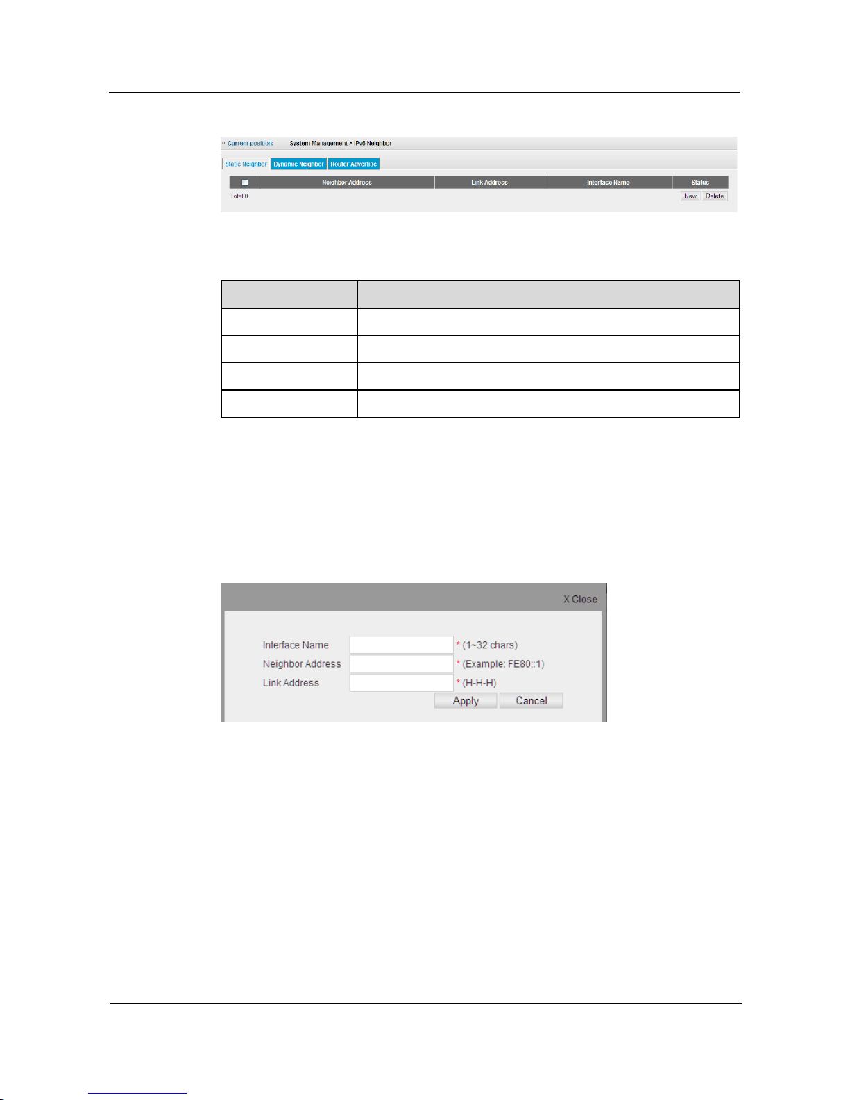
Click System Management > IPv6 Neighbor > Static Neighbor page to display and add IPv6
static neighborhood information, the configuration page is shown as the figure below.
Page 33
S1700 Managed Series Ethernet Switches
Web User Manual
3 System Management
S1700 Managed Series Ethernet Switches
Issue 05 (2012-10-25)
Huawei Proprietary and Confidential
Copyright © Huawei Technologies Co., Ltd.
23
Figure 3-14 Static Neighbor
Table 3-13 Parameters of Static Neighbor
Item
Description
Neighbor Address
IPv6 address of neighbor.
Link Address
MAC address of neighbor.
Interface Name
Name of the interface.
Status
Display the status of IPv6 neighbor address.
Static Neighbor Table Configuration
Step 1 Click System Management > IPv6 Neighbor > Static Neighbor.
Step 2 Click New button to add new static neighborhood information, as shown in following figure.
Figure 3-15 Edit Static Neighbor
Step 3 Enter relevant static neighborhood information.
Step 4 Click Apply to apply all the changes made.
----End
3.9.2 Dynamic Neighbor
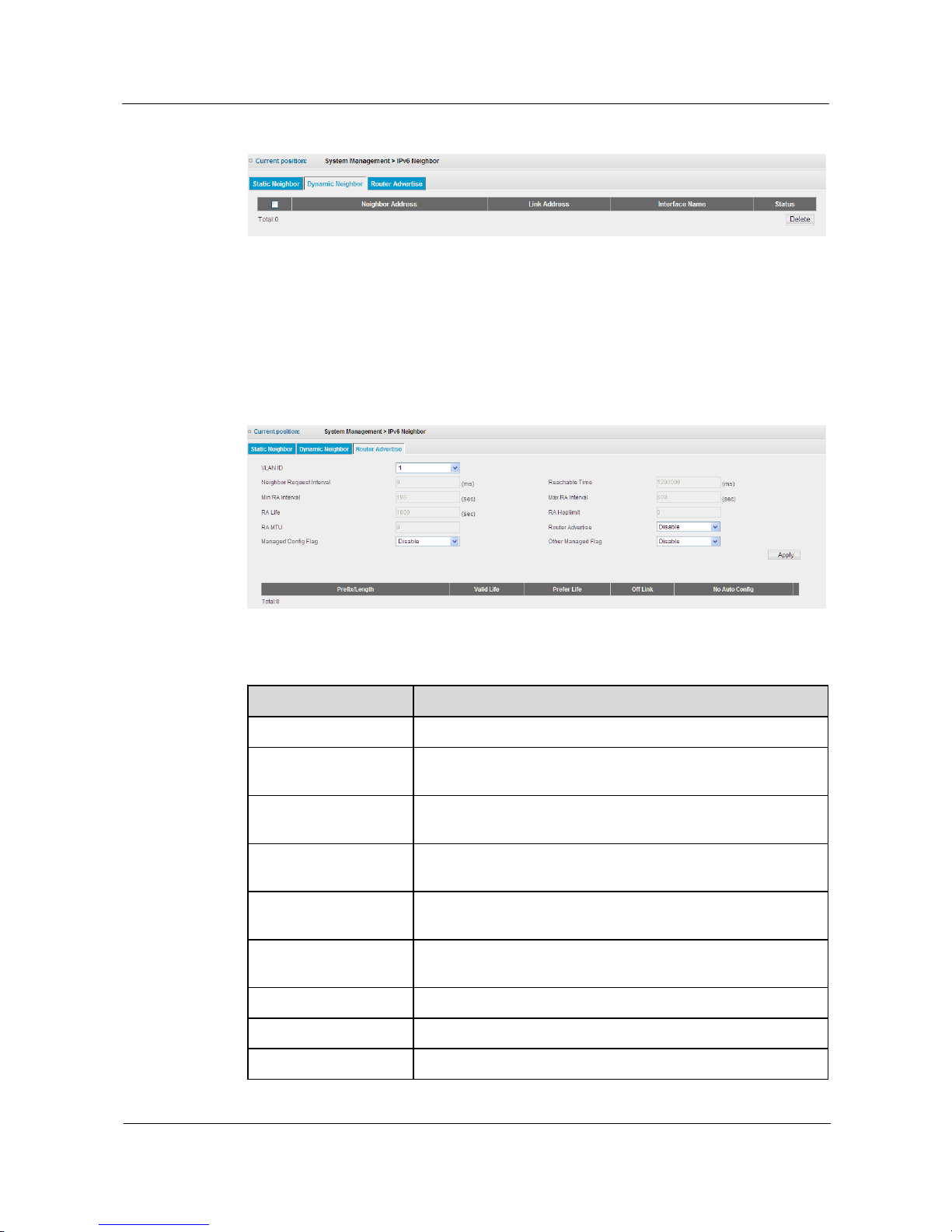
Click System Management > IPv6 Neighbor > Dynamic Neighbor page to display the IPv6
dynamic neighbor information detected by switch, the configuration page is shown as the
figure below.
Page 34
S1700 Managed Series Ethernet Switches
Web User Manual
3 System Management
S1700 Managed Series Ethernet Switches
Issue 05 (2012-10-25)
Huawei Proprietary and Confidential
Copyright © Huawei Technologies Co., Ltd.
24
Figure 3-16 Dynamic Neighbor
3.9.3 Router Advertise
Click System Management > IPv6 Neighbor > Router Advertise page to configure the IPv6
router advertisement information detected by switch, the configuration page is shown as the
figure below.
Figure 3-17 Router Advertise
Table 3-14 Parameters of Router Advertise
Item
Description
VLAN ID
Select the VLAN to which the router advertisement is attached.
Neighbor Request
Interval
Display the neighbor request interval of the router advertisement
in millisecond.
Reachable Time
Display the neighbor reachable time of the router advertisement
in millisecond, and 1200000 milliseconds is the default value.
Min RA Interval
Display the minimum interval of the router advertisement in
second, and 198 seconds is the default value.
Max RA Interval
Display the maximum interval of the router advertisement in
second, and 600 seconds is the default value.
RA Life
Display the lifetime of the router advertisement in second, and
1800 seconds is the default value.
RA Hoplimit
Display the hoplimit value of the router advertisement.
RA MTU
Display the MTU value of the router advertisement.
Router Advertise
Choose to enable/disable Router Advertise.
Page 35

S1700 Managed Series Ethernet Switches
Web User Manual
3 System Management
S1700 Managed Series Ethernet Switches
Issue 05 (2012-10-25)
Huawei Proprietary and Confidential
Copyright © Huawei Technologies Co., Ltd.
25
Item
Description
Managed Config Flag
Choose to enable/disable managed config flag.
Other Managed Flag
Choose to enable/disable other managed flag.
Prohibit Transmission of Router Advertisement
Step 1 Click System Management > IPv6 Neighbor > Router Advertise.
Step 2 Select Enable in the pull-down menu of RA Halt.
Step 3 Click Apply to halt router advertisement.
----End
Page 36
S1700 Managed Series Ethernet Switches
Web User Manual
4 Interface Management
Issue 05 (2012-10-25)
Huawei Proprietary and Confidential
Copyright © Huawei Technologies Co., Ltd.
26
4 Interface Management
About This Chapter
This chapter describes the interface configuration function of the switch.
4.1 Ethernet Interface
4.2 Eth-Trunk
4.1 Ethernet Interface
This section mainly describes how to configure and view interface connection.
4.1.1 Basic Attributes
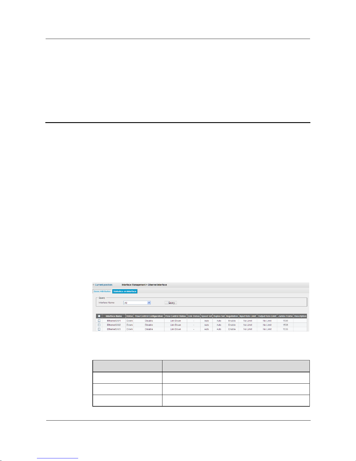
Click Interface Management > Ethernet Interface > Basic Attributes page to check each
interface status on switch, the configuration page is shown as the figure below.
Figure 4-1 Basic Attributes
Table 4-1 Parameters of Basic Attributes
Item
Description
Query
Search the basic attributes of the designated interface.
Interface Name
Display the number of interface.
Status
The operating status (up or down) on interface.
Page 37
S1700 Managed Series Ethernet Switches
Web User Manual
4 Interface Management
Issue 05 (2012-10-25)
Huawei Proprietary and Confidential
Copyright © Huawei Technologies Co., Ltd.
27
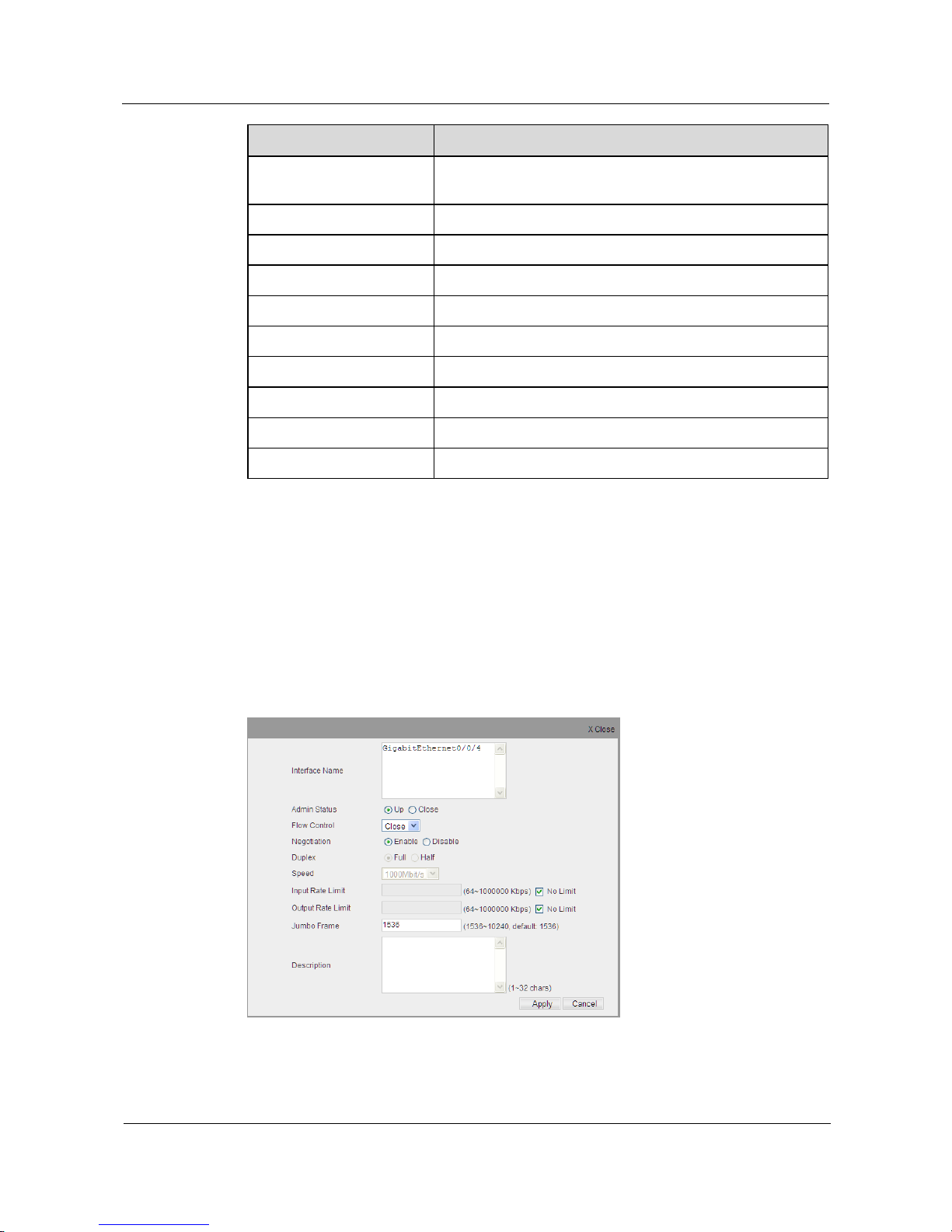
Item
Description
Flow Control
Configuration
Check if the flow control is enabled or disabled on the
interface.
Flow Control Status
Check whether the flow control is effective or not.
Link Status
Display the operating speed and duplex mode of the interface.
Speed Set
Display the current speed configuration on the interface.
Duplex Set
Display the current duplex configuration on the interface.
Negotiation
Display if the automatic negotiation is enabled or disabled.
Input Rate Limit
Input rate limit on interface.
Output Rate Limit
Output rate limit on interface.
Jumbo Frame
Size of Jumbo frame on interface.
Description
Description about the interface.
Interface Attribute Configuration
Step 1 Click Interface Management > Ethernet Interface > Basic Attributes.
Step 2 Choose the check box in the left-hand column of the interface to be configured with attributes
from the list, and then click Configure button to manually configure status for the designated
interface, including negotiation, interface speed, duplex mode and flow control, the
configuration page is shown as the figure below.
Figure 4-2 Basic Attributes Configuration
Page 38

S1700 Managed Series Ethernet Switches
Web User Manual
4 Interface Management
Issue 05 (2012-10-25)
Huawei Proprietary and Confidential
Copyright © Huawei Technologies Co., Ltd.
28
CAUTION
Interface auto-negotiation function must be disabled when user configures an interface
working in specified speed/duplex mode.
When auto-negotiation function is used, optimal configuration will be performed to link
among interfaces according to capability of two ends.
Speed and duplex of Giga SFP interface are fixed as 1000full.
Table 4-2 Parameters of Basic Attributes Configuration
Item
Description
Interface Name
Display the Interface number.
Admin Status
Enable/Disable the interface.
Flow Control
Enable/Disable flow control function of interface.
Negotiation
Enable/Disable automatic negotiation of interface.
Duplex
Configure duplex mode of interface.
Speed
Configure operation speed of interface.
Input Rate Limit
Configure input speed limit of interface.
Output Rate Limit
Configure output speed limit of interface.
Jumbo Frame
Specify the size of Jumbo frame on interface.
Description
Enter the description about interface.
Step 3 Configure parameters of interface.
Step 4 After that, click Apply to apply all the changes made. Use Basic Attributes page to view
status of valid switch interface.
----End
4.1.2 Statistics on Interface
Click Interface Management > Ethernet Interface > Statistics on Interface page to view
statistics information for each interface; statistics on interface is accounted after device startup
completed, the refresh frequency is 1/SEC.
Page 39
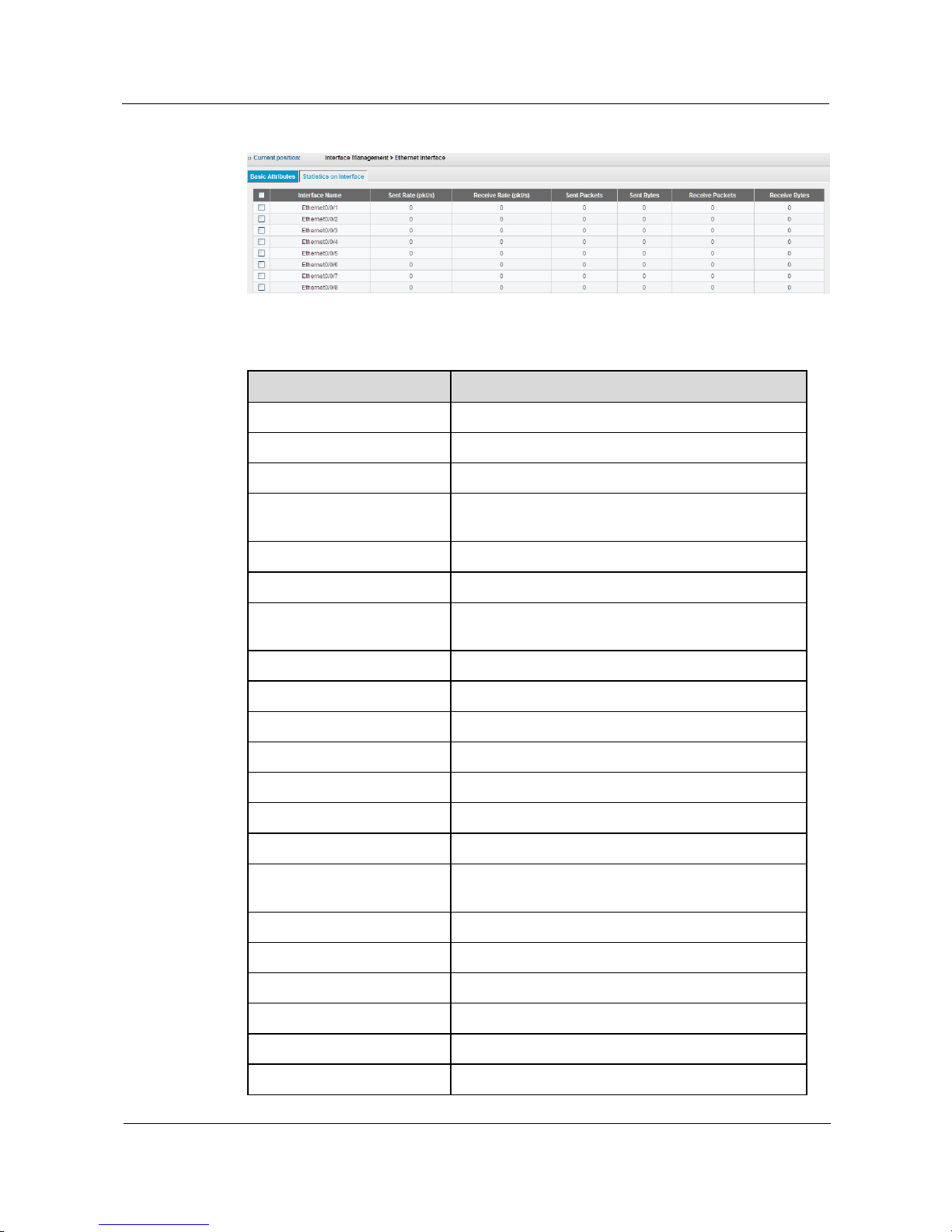
S1700 Managed Series Ethernet Switches
Web User Manual
4 Interface Management
Issue 05 (2012-10-25)
Huawei Proprietary and Confidential
Copyright © Huawei Technologies Co., Ltd.
29
Figure 4-3 Statistics on Interface
Table 4-3 Parameters of Statistics on Interface
Item
Description
Interface Name
Interface number.
Sent Rate
Send rate of the packet on this interface.
Sent Packets
Total packets sent on this interface.
Sent Bytes
Total bytes including frame characters sent on this
interface.
Receive Rate
Receive rate of the packet on this interface.
Received Packets
Total packets received on this interface.
Receive Bytes
Total bytes including frame characters received on this
interface.
Unicast Packets
Total unicast packets received on this interface.
Broadcast Packets
Total broadcast packets received on this interface.
Multicast Packets
Total multicast packets received on this interface.
Received Error Packets
Total error packets received on this interface.
Runts Error Packets
Total runts error packets received on this interface.
CRC Error Packets
Total CRC error packets received on this interface.
Frame Error Packets
Total Frame error packets received on this interface.
Alignments Error Packets
Total Alignment error packets received on this
interface.
Symbols Error Packets
Total symbols error packets received on this interface.
Dropped packet
The sum of dropped packets on this interface.
Unicast Packets
Total unicast packets transmitted on this interface.
Broadcast Packets
Total broadcast packets transmitted on this interface.
Multicast Packets
Total multicast packets transmitted on this interface.
Delayed Frames
Total delayed frames transmitted on this interface.
Page 40
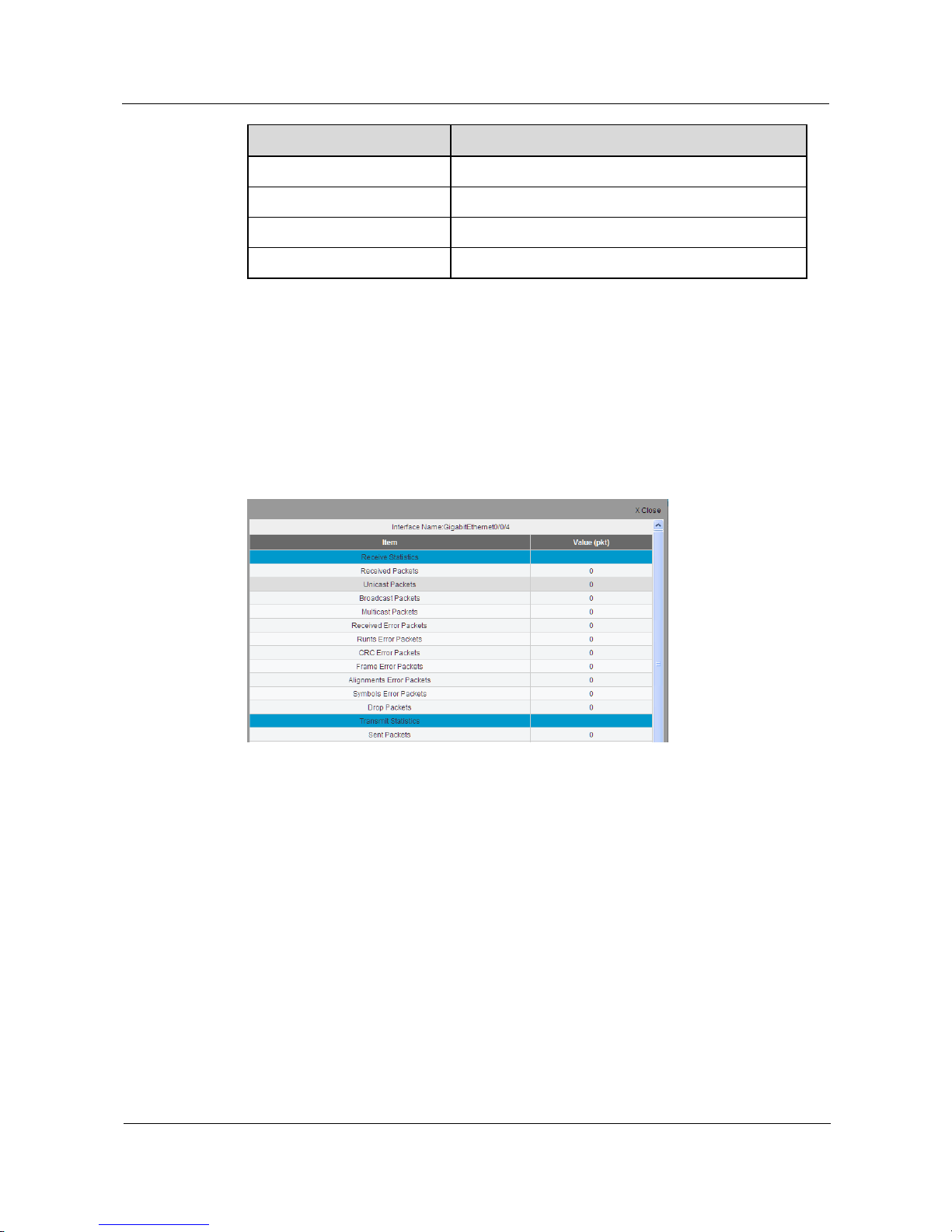
S1700 Managed Series Ethernet Switches
Web User Manual
4 Interface Management
Issue 05 (2012-10-25)
Huawei Proprietary and Confidential
Copyright © Huawei Technologies Co., Ltd.
30
Item
Description
Collision on the Interface
Total collision packets transmitted on this interface.
Giants Error Packets
Total Giants error packets transmitted on this interface.
CRC Error Packets
Total CRC error packets transmitted on this interface.
Aborts Error Packets
Total Aborts error packets transmitted on this interface.
Details of Statistics on Interface
Step 1 Click Interface Management > Ethernet Interface > Statistics on Interface.
Step 2 Choose the check box in the left-hand column of the interface to be viewed for details from
the list, and then click Details button to view the detailed statistics data of designated interface,
the configuration page is shown as the figure below.
Figure 4-4 Details of Statistics on Interface
Step 3 Click Close, to return to the configuration page of Statistics on Interface.
----End
4.2 Eth-Trunk
This section describes a method to configure Eth-Trunk.
User is allowed to set up multiple links among multiple switches. Link Aggregation is a
method of binding a group of physical interfaces as a logical interface to increase bandwidth.
At most 12 manual Trunks and static LACP can be set up at the same time.
This device supports manual Trunk and link aggregation control protocol (only supports static
LACP). Manual Trunk needs a manual setting of links at both ends, and must be compatible
with Cisco EtherChannel standard. On the other hand, a Trunk link can be connected between
the LACP interface of a device and that of another device. User is allowed to configure any
member with an interface number of LACP as long as these numbers are not configured as
Page 41
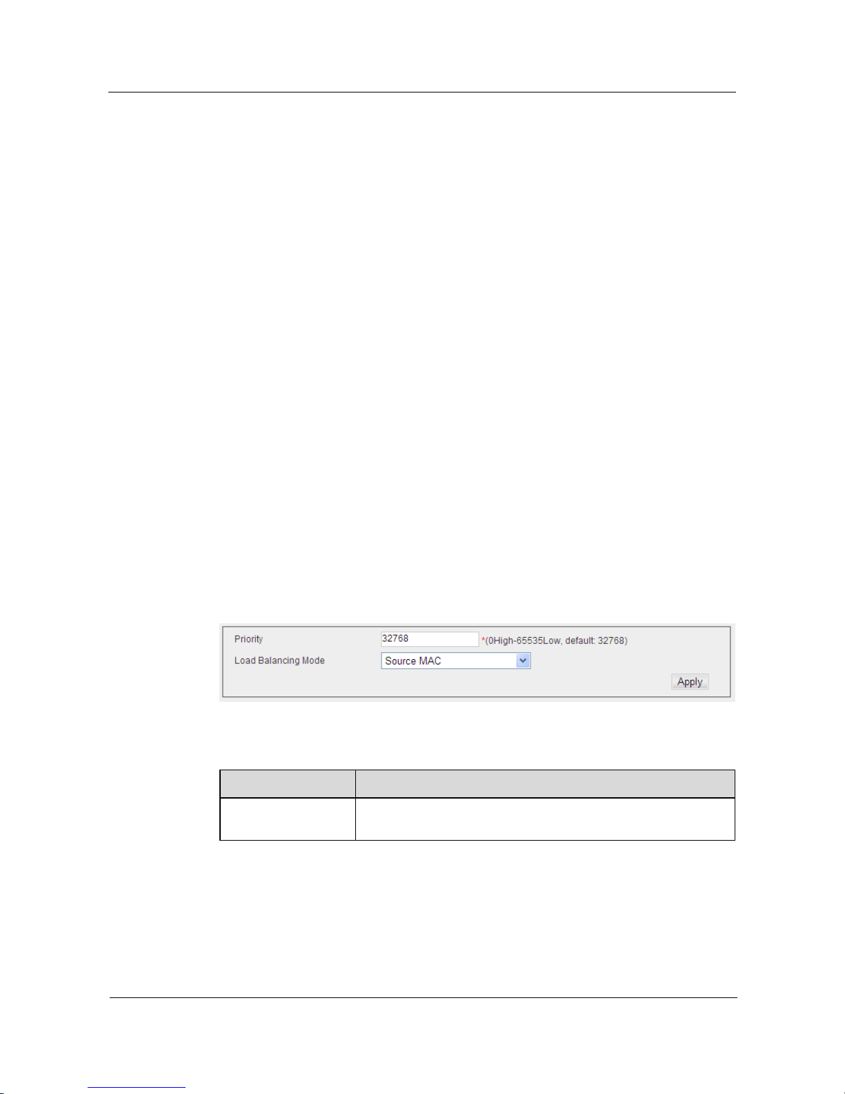
S1700 Managed Series Ethernet Switches
Web User Manual
4 Interface Management
Issue 05 (2012-10-25)
Huawei Proprietary and Confidential
Copyright © Huawei Technologies Co., Ltd.
31
other Trunk links. If the interface of another device is also configured as LACP, thus a Trunk
link can be set up between the switch and the device.
In addition to balancing load of each interface of Trunk link, the member interfaces of Trunk
link also provides a backup function, to ensure Trunk operates properly in case that one
interface of them fails. But before automatic setup of any physical connection among devices,
it is necessary to specify the member interfaces at both ends of Trunk link by user interface.
When using the interface Trunk, please note the following points:
Before connection of network cable, user needs to configure interface Trunk, to avoid
forming of loop.
Up to 12 Trunks can be set up on one switch, each of them including up to 8
interfaces.
Interfaces of connecting two ends must be configured as Trunk member interfaces.
When manual Trunks are configured on different types of switches, the switches must
be compatible with Cisco EtherChannel standard.
Trunk members must be configured in the same mode, including communication
mode (e.g. flow control and interface negotiation modes) and CoS setting.
Any Giga interface of device front panel can be configured as Trunk, including
different media types of interfaces.
Interfaces of the same Trunk are all taken as a whole, which can be added to a VLAN,
or completely deleted or moved from a VLAN.
Same STP, VLAN and IGMP settings will be applied to all interfaces of the trunk.
4.2.1 System Priority Configuration
Click Interface Management > Eth-Trunk page to set Trunk, the configuration page is shown
as the figure below.
Figure 4-5 System Priority Configuration
Table 4-4 Parameters of System Priority Configuration
Item
Description
Priority
Set LACP priority level of switch (Range: 0-65535; Default:
32768).
Page 42

S1700 Managed Series Ethernet Switches
Web User Manual
4 Interface Management
Issue 05 (2012-10-25)
Huawei Proprietary and Confidential
Copyright © Huawei Technologies Co., Ltd.
32
Item
Description
Load Balancing Mode
Select the standard of flow distribution among member interfaces
on Trunk group. The options are:
Source MAC
Destination MAC
Source and Destination MAC
Source IP
Destination IP
Source and Destination IP
4.2.2 Trunk Configuration
Click Interface Management > Eth-Trunk to enter configuration page where Trunk can be set
up, to configure member interface number and configure connection parameters
Figure 4-6 Trunk List
Table 4-5 Parameters of Trunk List
Item
Description
Trunk ID
Configured trunk number (Range: 1-12)
Types
Manual Trunk or Static LACP mode supports 12 Trunks
(up to eight member interfaces in each group).
Min Active Links
The minimum active interfaces in the group.
Max Active Links
The maximum active interfaces in the group.
Preempt Delay State
The active port with lower priority in LACP aggregation
group can be replaced by the backup port with higher
priority when LACP Preempt is enabled, at this time the
port with higher priority will become active port, and the
port with lower priority become the secondary port. If
LACP Preempt is disabled, the replacement will not
happen.
Preempt Delay Time(s)
The backup port with higher priority replaces the active
port with lower priority after a designated time. It will only
relevant when LACP Preempt is enabled.
Select interface
The interface number set as Trunk member.
Page 43
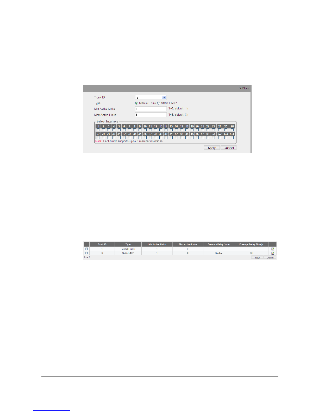
S1700 Managed Series Ethernet Switches
Web User Manual
4 Interface Management
Issue 05 (2012-10-25)
Huawei Proprietary and Confidential
Copyright © Huawei Technologies Co., Ltd.
33
Add a Trunk Group
Step 1 Click Interface Management > Eth-Trunk, to display a page as shown in Figure 4-6.
Step 2 Click New button, and add a Trunk group to display a page as shown in following figure.
Figure 4-7 Add a Trunk
Step 3 Enter corresponding parameters of Trunk on configuration page.
Step 4 Click Apply to apply all the changes made.
----End
Display/Delete Trunk group
Step 1 Click Interface Management > Eth-Trunk, to display a page as shown in Figure 4-8, the list
shows all Trunks created on switch.
Figure 4-8 Display Trunk List
Step 2 Choose the check box in the left-hand column of Trunk to be deleted, then click Delete button
to delete Trunk.
----End
Configure Trunk Attribute List
Step 1 Click Interface Management > Eth-Trunk, to display a page as shown in Figure 4-8.
Step 2 Click Edit icon in the right-hand column of Trunk to be configured.
Step 3 Configure the required Trunk parameters.
Step 4 Click Apply to apply all the changes made.
----End
Page 44
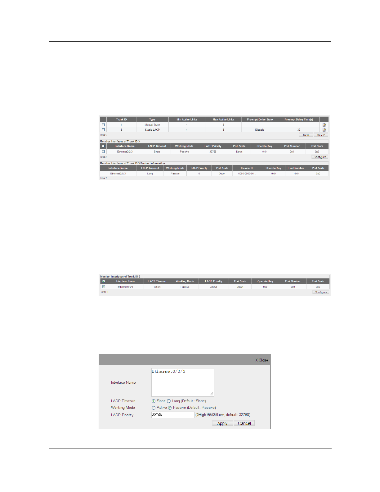
S1700 Managed Series Ethernet Switches
Web User Manual
4 Interface Management
Issue 05 (2012-10-25)
Huawei Proprietary and Confidential
Copyright © Huawei Technologies Co., Ltd.
34
Display Trunk Member List
Step 1 Click Interface Management > Eth-Trunk, to display a page as shown in Figure 4-8.
Step 2 Click the Trunk entries to be viewed in Trunk list, the detailed member information of the
chosen Trunk will be displayed in lists of Trunk ID Member and Trunk ID Member Patner
Information, as shown in following figure.
Figure 4-9 Display Trunk Member List
----End
Configure LACP Member
Step 1 Click Interface Management > Eth-Trunk, to display a page as shown in Figure 4-8.
Step 2 Click the LACP entries to be viewed in Trunk list, the detailed member information of the
chosen Trunk will be displayed in Trunk ID Member list, as shown in following figure.
Figure 4-10 Configure LACP Member
Step 3 Click the check box in the left-hand column of the interface to be modified on attributes from
Trunk Member list, click Configure button of the list, and edit attributes of the designated
interface.
Figure 4-11 Edit Member Attributes
Page 45
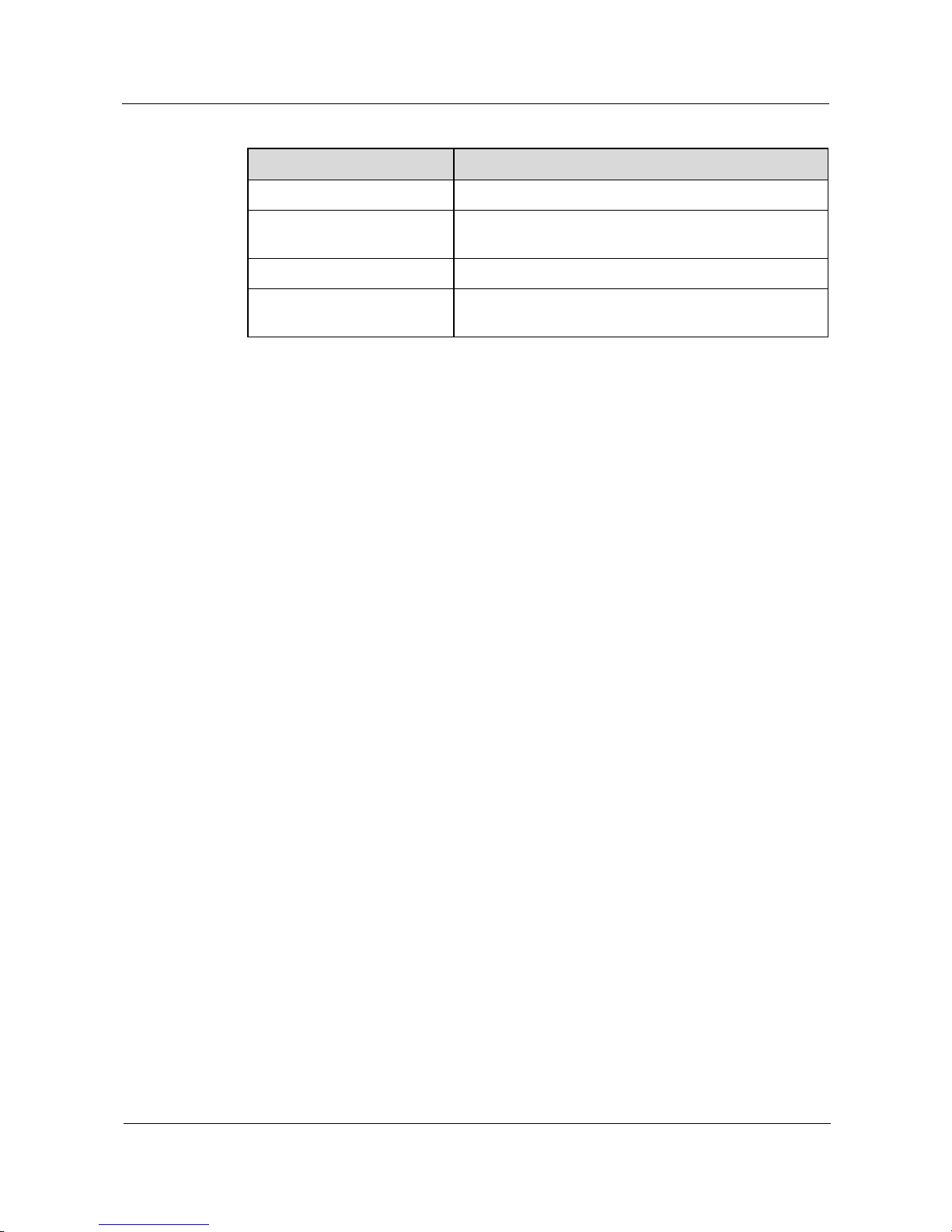
S1700 Managed Series Ethernet Switches
Web User Manual
4 Interface Management
Issue 05 (2012-10-25)
Huawei Proprietary and Confidential
Copyright © Huawei Technologies Co., Ltd.
35
Table 4-6 Parameters of Member Attributes
Item
Description
Interface Name
Interface number.
LACP Timeout
Specify LACP message timeout, selecting Short means
three seconds, selecting Long means ninety seconds.
Working Mode
Specify LACP operation mode of interface
LACP Priority
Specify LACP priority of interface (Range: 0–65535;
Default: 32768)
Step 4 Configure the parameters needed.
Step 5 Click Apply button to apply all the changes made.
----End
Page 46

S1700 Managed Series Ethernet Switches
Web User Manual
5 Service Management
Issue 05 (2012-10-25)
Huawei Proprietary and Confidential
Copyright © Huawei Technologies Co., Ltd.
36
5 Service Management
About This Chapter
This chapter mainly describes VLAN, STP and IGMP Snooping relevant configurations of the
switch.
5.1 VLAN
5.2 MAC VLAN
5.3 Voice VLAN
5.4 MAC
5.5 STP
5.6 IGMP Snooping
5.1 VLAN
VLAN (Virtual Local Area Network) means logically dividing a LAN (Local Area Network)
into many different subsets, and each subset will form its own broadcast domain. In short,
VLAN is a telecommunication technology dividing a physical LAN into many broadcast
domains. The hosts in VLAN can directly communicate with each other, while VLANs can
not directly intercommunicate. Therefore, the broadcast message is limited in a VLAN. The
network security is improved.
You can create, edit or delete VLAN in Service Management > VLAN > VLAN to display
members based on VLAN.
In the Service Management > VLAN > Interface page, you can edit/display members
according to interface or interface range.
5.1.1 VLAN
Click Service Management > VLAN > VLAN page to view the configured VLAN on the
switch, the configuration page is shown as the figure below.
Page 47
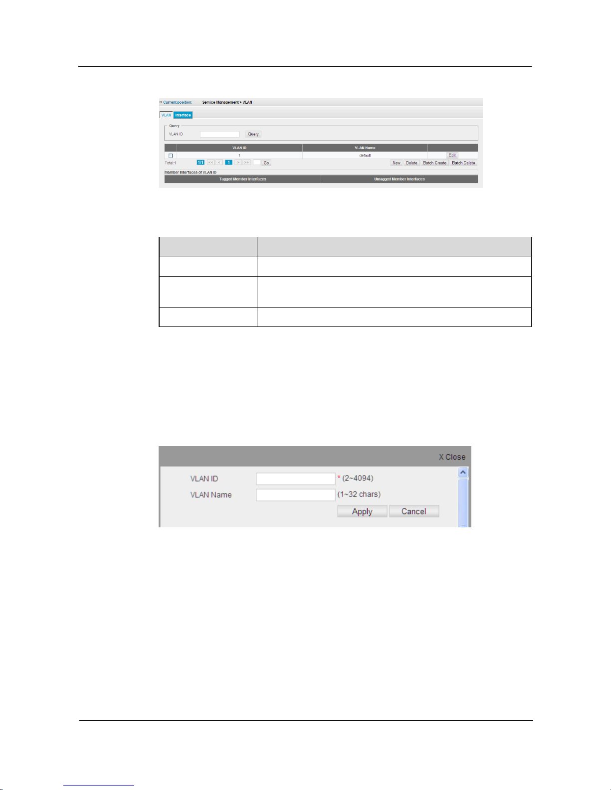
S1700 Managed Series Ethernet Switches
Web User Manual
5 Service Management
Issue 05 (2012-10-25)
Huawei Proprietary and Confidential
Copyright © Huawei Technologies Co., Ltd.
37
Figure 5-1 Static VLAN List
Table 5-1 Parameters of Static VLAN List
Item
Description
Query
Search the designated VLAN information through VLAN ID.
VLAN ID
VLAN ID numbers. Up to 4094 VLAN groups can be defined.
VLAN 1 is the default untagged VLAN.
VLAN Name
Name of the VLAN.
Add a Static VLAN
Step 1 Click Service Management > VLAN > VLAN, the configuration page is as shown in Fig.5-1.
Step 2 Click New button to add VLAN, the configuration page is as shown in following figure.
Figure 5-2 Add VLAN
Step 3 Enter VLAN ID and VLAN names, parameters are as shown in Fig.5-1
Step 4 Click Apply to apply all the changes made.
----End
Page 48
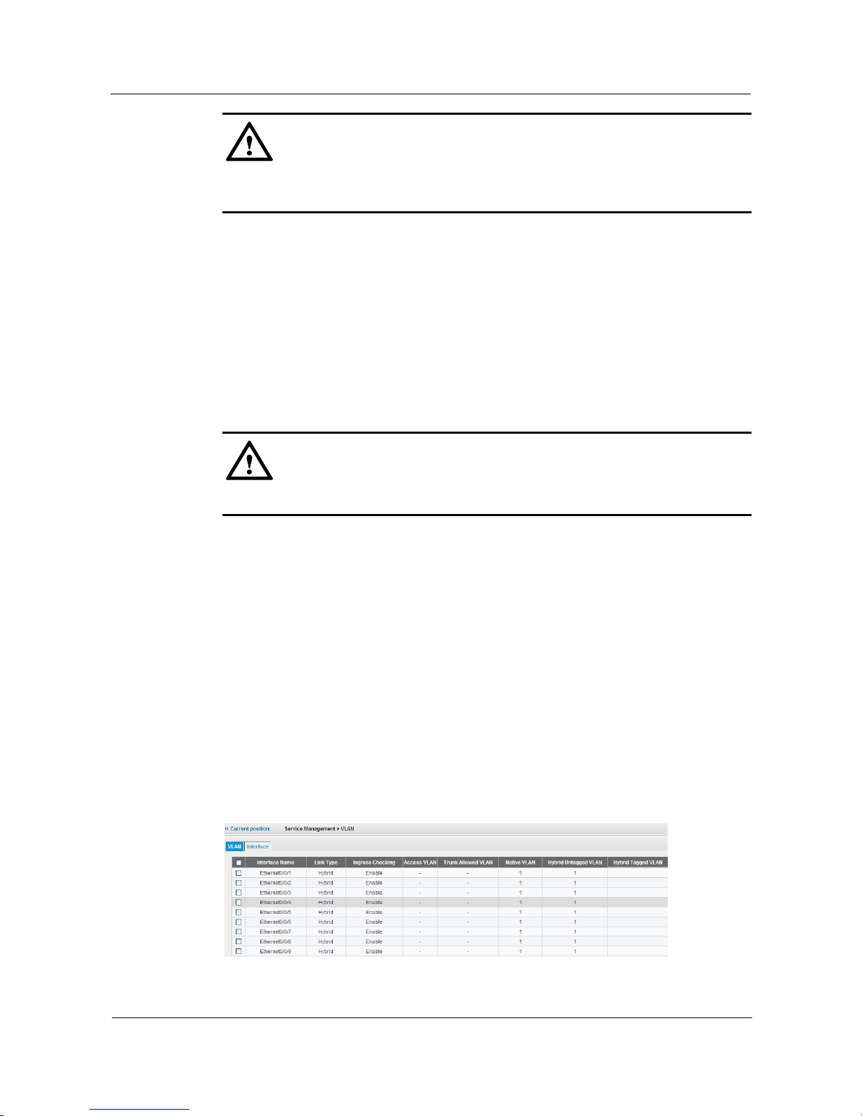
S1700 Managed Series Ethernet Switches
Web User Manual
5 Service Management
Issue 05 (2012-10-25)
Huawei Proprietary and Confidential
Copyright © Huawei Technologies Co., Ltd.
38
CAUTION
At most 4094 VLANs can be configured to this switch. VLAN 1 is the default Untagged
VLAN.
View/Delete Static VLAN
Step 1 Click Service Management > VLAN > VLAN to view the settings of static VLAN, the
configuration page is as shown in Fig.5-1.
Step 2 Click the check box in the left-hand column of VLAN entries to be deleted, the member
information of the VLAN is displayed in VLAN ID Member list.
Step 3 Click Delete button to delete static VLAN.
----End
CAUTION
VLAN 1 cannot be deleted.
Modify VLAN
Step 1 Click Service Management > VLAN > VLAN to modify the basic information of VLAN, the
configuration page is as shown in Fig.5-1.
Step 2 Choose the Edit button in the right-hand column of VLAN entries to be modified to modify
the name of VLAN.
Step 3 After modification, click Apply to apply all the changes made.
----End
5.1.2 Interface
Click Service Management > VLAN > Interface page to view/edit VLAN members' attribute,
as shown in Fig.5-3
Figure 5-3 Interface VLAN Attributes
Page 49

S1700 Managed Series Ethernet Switches
Web User Manual
5 Service Management
Issue 05 (2012-10-25)
Huawei Proprietary and Confidential
Copyright © Huawei Technologies Co., Ltd.
39
Table 5-2 Parameters of Interface VLAN Attributes
Item
Description
Interface Name
Display a list of interface.
Link Type
Indicate VLAN membership mode for an interface (default:
Hybrid).
Access: set the port as an Access VLAN interface. The port
transmits tagged or untagged frames on a single VLAN
only.
Hybrid: specify an interface as hybrid VLAN interface. The
port may transmit tagged or untagged frames.
Trunk: specify an interface as VLAN Trunk interface. A
trunk is a direct link between two switches, so the interface
transmits tagged frames marked the source VLAN. Note
that frames belonging to the interface's default VLAN are
also transmitted as untagged frames.
Ingress Checking
Determine how to process the tagged frame, which is not
included in this VLAN. (Default: Enable)
Ingress filtering only affects tagged frames.
If ingress filtering is disabled and the interface receives a
tagged frame which is not included in this VLAN, these
frames will be flooded to all other ports within this VLAN.
If ingress filtering is enabled and the interface receives a
tagged frame, which is not included in this VLAN, then the
frame will be dropped.
Ingress filtering does not affect VLAN independent BPDU
frames, such as GVRP or STP. However, they do affect
VLAN associated BPDU frames, such as GMRP.
Access VLAN
If the displayed link type is Access, the VLAN ID that the
interface belongs to, and the tagged or untagged frames
received on the interface will be tagged with the VLAN ID
(default : 1). The option can only be used when the link type
is Access.
Trunk Allowed VLAN
If the displayed link type is Trunk, VLAN ID or list is
allowed to pass through the interface. This can only be used
when the link type is Trunk.
Native VLAN
The VLAN ID (default: 1) of untagged frame which is
received on interface. If the received frame is untagged
frame, the frame will be added default VLAN ID. This can
only be used when the link type are Trunk and Hybrid.
Hybrid Untagged VLAN
If the link type is Hybrid, the untagged VLAN ID or list is
allowed to pass through the interface. This can only be used
when the link type is Hybrid.
Hybrid Tagged VLAN
If the link type is Hybrid, the Tagged VLAN ID or list is
allowed to pass through the interface. This can only be used
when the link type is Hybrid.
Page 50
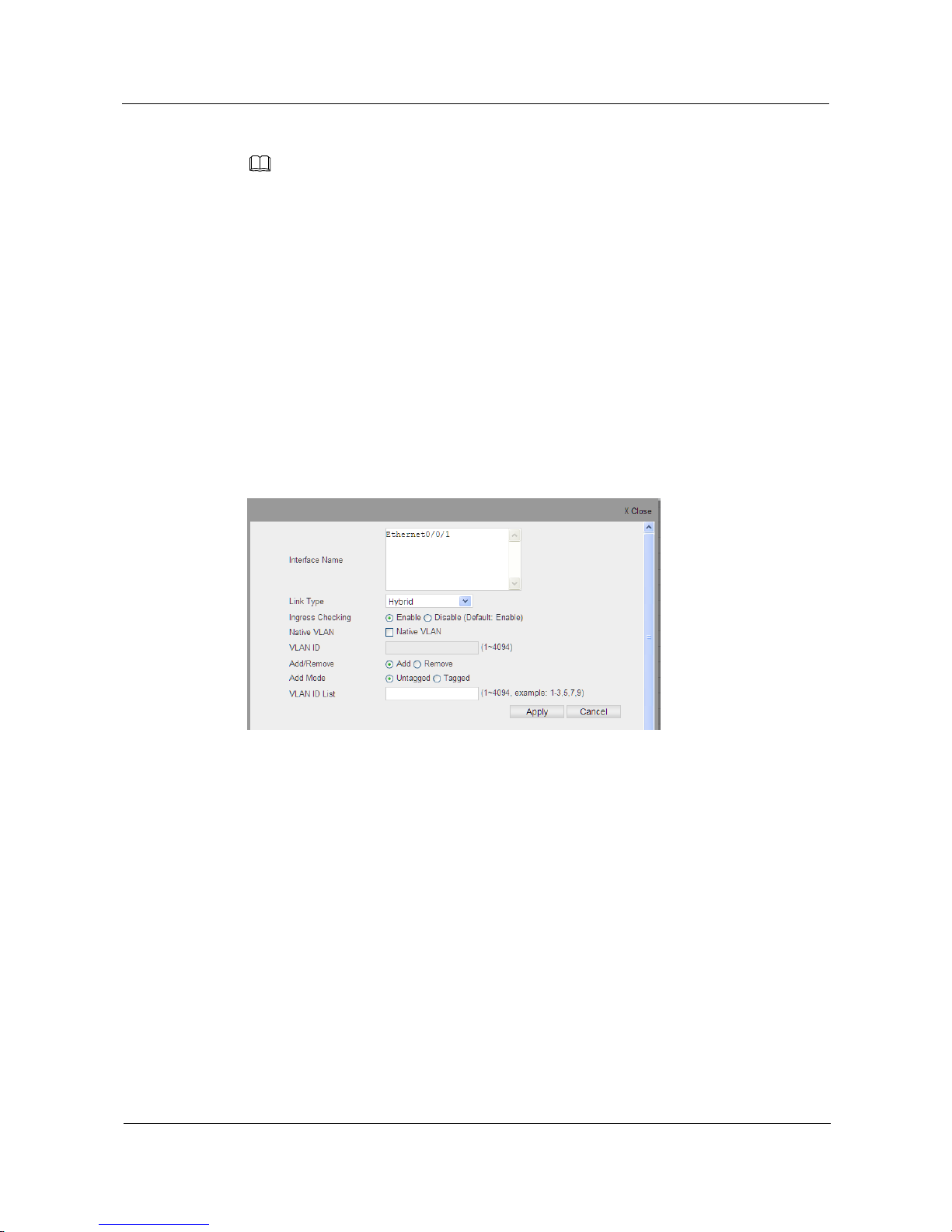
S1700 Managed Series Ethernet Switches
Web User Manual
5 Service Management
Issue 05 (2012-10-25)
Huawei Proprietary and Confidential
Copyright © Huawei Technologies Co., Ltd.
40
NOTE
VLAN 1 is the default untagged VLAN, including all interfaces of switch and using Hybrid mode.
VLAN 1 is a default untagged VLAN, including all the interfaces on the switch and using Hybrid mode.
When Eth-Trunk is used, the VLAN attribute of Eth-Trun interface will follow the principles below:
1)If Eth-Trunk is created, the VLAN attribute of Eth-Trunk interface is set as default value;
2)If added to Eth-Trunk, the interface will be not displayed in VLAN interface list;
3)If removed from Eth-Trunk,the VLAN attribute of original interface will recover.
Edit VLAN Attribute based on Interface or Interface Range
Step 1 Click Service Management > VLAN > Interface, to open a page as shown in Fig.5-3.
Step 2 Choose the check box in the left-hand column of the interface to be edited, and then click
Configure button to modify the VLAN attribute of interface. The configuration page is shown
as the figure below.
Figure 5-4 Edit VLAN Member Attribute
Step 3 Modify corresponding configuration item, the parameters are as shown in Fig.5-2.
Step 4 After configuration, click Apply button to apply all the changes made.
----End
5.2 MAC VLAN
MAC VLAN is another partition method of VLAN, which defines the VLAN membership
according to the source MAC address of message and sends the specified message marked
with VLAN Tag. If the interface uses MAC VLAN partition mechanism, it will take the
following methods when the message arrives:
The source MAC will try to match the MAC-VLAN entry if the received message is
untagged or priority tagged. If the match succeeds, the message will be tagged with
specified VLAN ID in table. If the match fails, the message will be matched
according to other principles.
Page 51
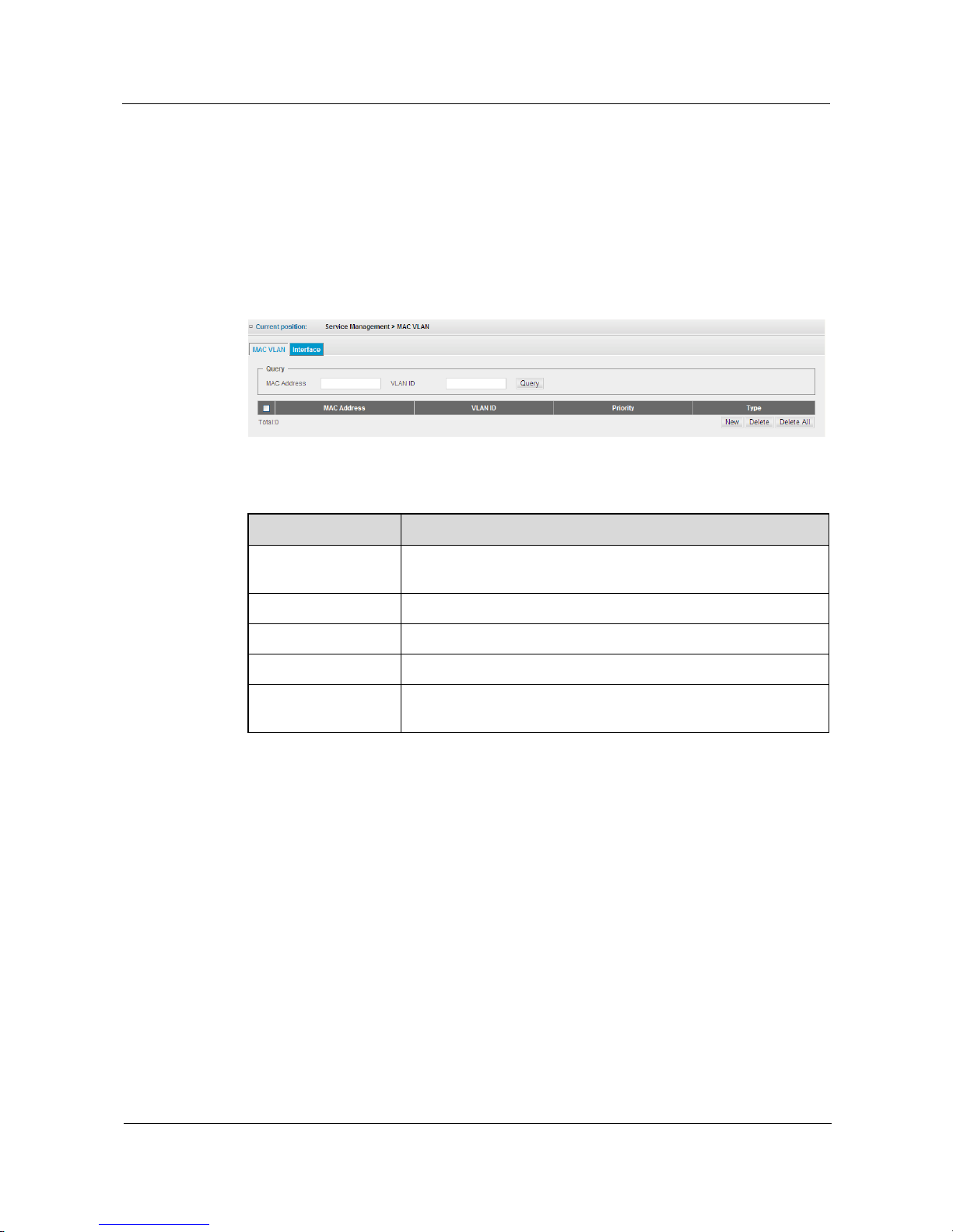
S1700 Managed Series Ethernet Switches
Web User Manual
5 Service Management
Issue 05 (2012-10-25)
Huawei Proprietary and Confidential
Copyright © Huawei Technologies Co., Ltd.
41
If the received message is tagged, the same methods will be applied as port-based
VLAN: if the port allows the message marked with VLAN tag to pass through, then
the message will be forwarded normally; if not allowed, the message will be dropped.
5.2.1 MAC VLAN
Click Service Management > MAC VLAN > MAC VLAN page to check the list of MAC
VLAN configured on the switch, the configuration page is shown as the figure below.
Figure 5-5 MAC VLAN
Table 5-3 Parameters of MAC VLAN
Item
Description
Query
Search the designated MAC VLAN information through MAC
address and VLAN ID.
MAC Address
MAC address of the computer, the format is H-H-H.
VLAN ID
The VLAN ID for this MAC address.
Priority
Priority value is 0-7.
Type
The manually established type is static and the type automatically
established according to other protocols is dynamic.
Create a Static MAC VLAN
Step 1 Click Service Management > MAC VLAN > MAC VLAN, the configuration page is as
shown in Fig.5-5
Step 2 Click New button to add MAC VLAN, the configuration page is shown as the figure below.
Page 52
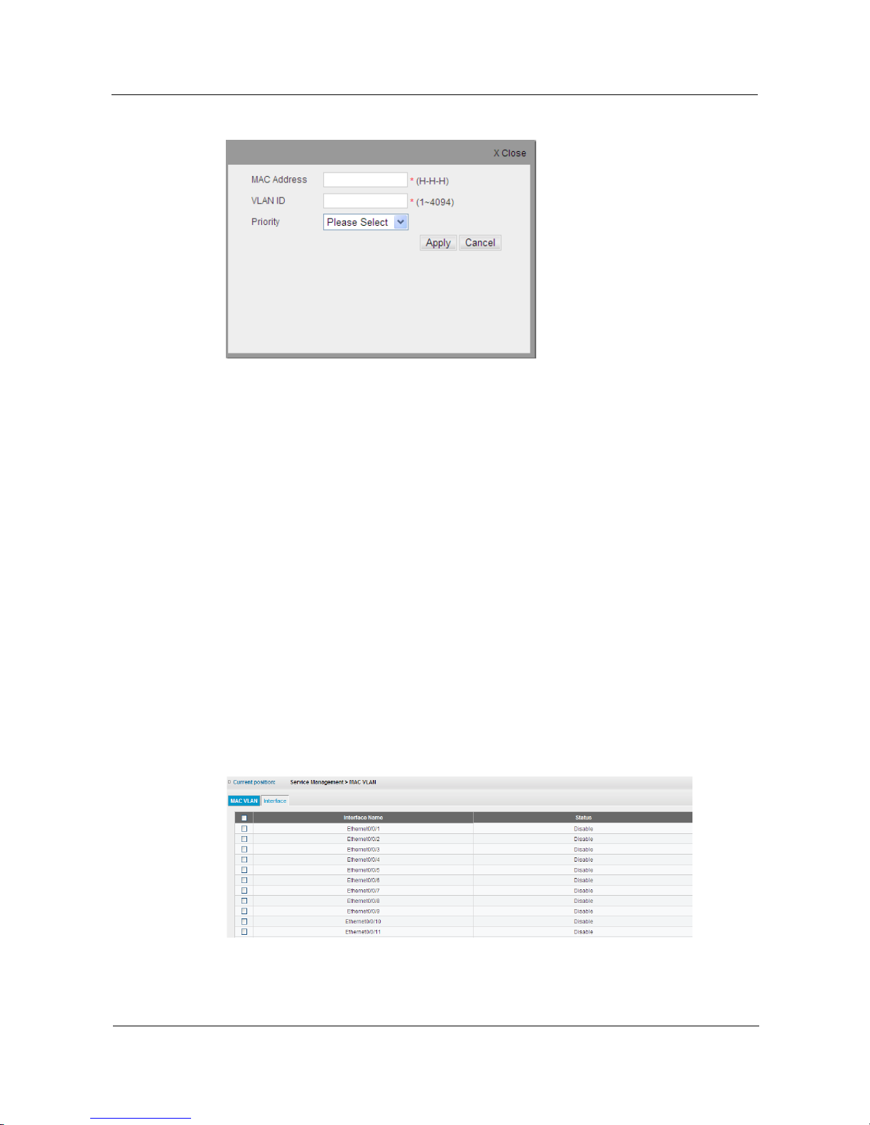
S1700 Managed Series Ethernet Switches
Web User Manual
5 Service Management
Issue 05 (2012-10-25)
Huawei Proprietary and Confidential
Copyright © Huawei Technologies Co., Ltd.
42
Figure 5-6 Add MAC VLAN
Step 3 Enter MAC address, VLAN ID and priority, parameters are as shown in Table 5-3.
Step 4 Click Apply button to apply all the changes made.
----End
View/Delete MAC VLAN
Step 1 Click Service Management > MAC VLAN > MAC VLAN to view the settings of MAC
VLAN, as shown in Fig.5-5.
Step 2 Choose the check box in the left-hand column of the VLAN entry needed to be deleted.
Step 3 Click Delete button to delete MAC VLAN.
----End
5.2.2 Interface
Click Service Management > MAC VLAN > Interface page to open the configuration page as
shown below, which displays all function status information of MAC VLAN on all interfaces
Figure 5-7 Attribute of MAC VLAN Interface
Page 53
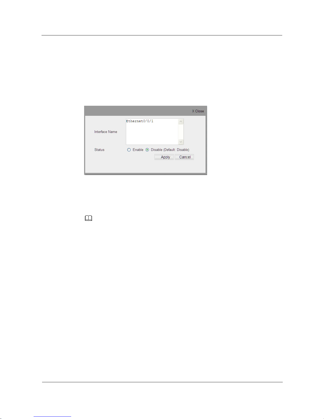
S1700 Managed Series Ethernet Switches
Web User Manual
5 Service Management
Issue 05 (2012-10-25)
Huawei Proprietary and Confidential
Copyright © Huawei Technologies Co., Ltd.
43
View/Enable MAC VLAN based on Interface or Interface Range
Step 1 Click Service Management > MAC VLAN > Interface to open the configuration page as
shown in Fig.5-7.
Step 2 Choose the check box in the left-hand column of the interface list needed to be edited, and
then click Configure button to modify the MAC VLAN attribute of interface; the
configuration page is shown as the figure below..
Figure 5-8 Edit MAC VLAN Function of Interface
Step 3 Click Enable button to enable MAC VLAN function of the interface.
----End
NOTE
MAC VLAN can be enabled only on hybrid interface.
When Eth-Trunk is used, the MAC VLAN attribute of Eth-Trunk interface will follow the principles
below:
1) If Eth-Trunk is created, the MAC VLAN attribute of Eth-Trunk interface is set as default value;
2) If added to Eth-Trunk, the interface will be not displayed in MAC VLAN interface list;
3) If removed from Eth-Trunk,the MAC VLAN attribute of original interface will recover.
5.3 Voice VLAN
It is recommended that the VoIP network traffic should be separated from other data traffics
when deploying IP technology in enterprise network. Flow separation can prevent data packet
delay, packet loss and the blocking effect of voice, through distributing all the VoIP traffic into
an independent Voice VLAN, thus ensures higher voice quality.
The usage of Voice VLAN can bring many benefits to users. It provides a higher security by
separating VoIP traffic from other traffics. In network, Voice VLAN ensures the necessary
bandwidth to transmit voice by using end-to-end QoS policy and high priority. VLAN
separation also protects against the unnecessary broadcast and multicast traffic, which will
seriously affect the voice quality.
This switch allows user to specify a Voice VLAN for network, and set the CoS priority for
Voice VLAN traffic. Voice VLAN traffic can detect the VoIP device connected to network
through the source MAC address of packets. When Voice VLAN traffic is detected on an
Page 54

S1700 Managed Series Ethernet Switches
Web User Manual
5 Service Management
Issue 05 (2012-10-25)
Huawei Proprietary and Confidential
Copyright © Huawei Technologies Co., Ltd.
44
interface, the switch will automatically assign a Voice VLAN member tag for that interface. In
addition, users can also connect the interface to Voice VLAN members manually.
5.3.1 Global Parameter Configuration
Click Service Management > Voice VLAN > Global page to configure Voice VLAN global
parameters for switch, the configuration page is shown as the figure below.
Figure 5-9 Voice VLAN Global Settings
Table 5-4 Parameters of Voice VLAN Global Settings
Item
Description
Global State
Enable automatic VoIP flow detection on the interface of switch (the
default is disable).
VLAN ID
Set VLAN ID of enabled Voice VLAN. Voice VLAN is only enabled
on one VLAN.
VLAN Name
Set VLAN name of enabled Voice VLAN. Voice VLAN is only
enabled on one VLAN.
Priority
Define CoS priority of interface in Voice VLAN. When Voice VLAN
is opened, the interface will forward the data based on the CoS field in
message. (Range: 0-7; Default: 6)
Aging Time
The interface will be deleted from Voice VLAN if it no longer receives
the VoIP traffic during a certain time (Range: 5-43200 minutes;
Default: 1440 minutes)
Configure VLAN ID of Voice VLAN as 2
Step 1 Click Service Management > Voice VLAN > Global.
Step 2 Choose Enable under Global State to enable Voice VLAN.
Step 3 Specified ID of VLAN ID is 2.
Page 55
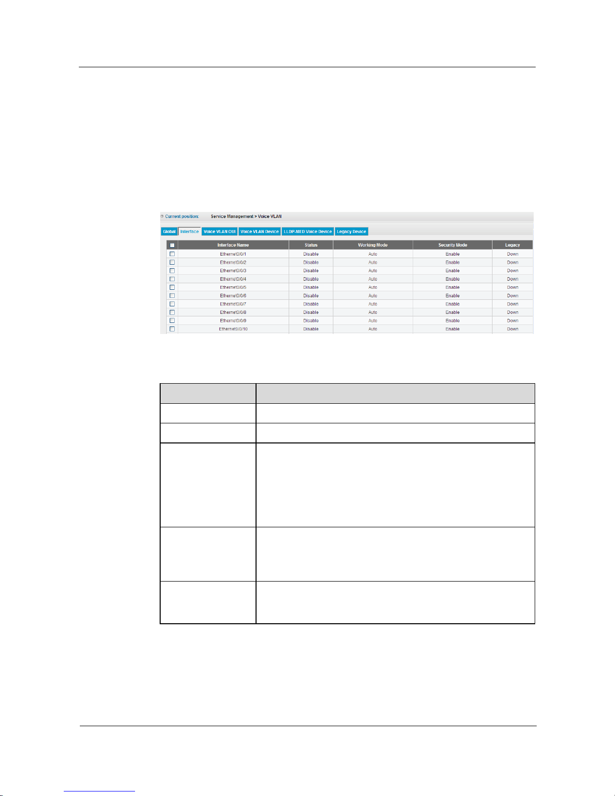
S1700 Managed Series Ethernet Switches
Web User Manual
5 Service Management
Issue 05 (2012-10-25)
Huawei Proprietary and Confidential
Copyright © Huawei Technologies Co., Ltd.
45
Step 4 Click Apply button to apply all the changes made.
----End
5.3.2 Interface
Click Service Management > Voice VLAN > Interface page to configure Voice VLAN based
on interface, the configuration page is shown as the figure below.
Figure 5-10 Voice VLAN Interface
Table 5-5 Parameters of Voice VLAN Interface
Item
Description
Interface Name
Interface number.
Status
Display if the Voice VLAN function will be enabled on interface.
Working Mode
Specify if the interface will be added to the Voice VLAN when
VoIP traffic is detected.
Auto: the interface will be added as a tagged member to the Voice
VLAN after traffic is detected.
Manual: the interface will be manually added to the Voice VLAN
after the Voice VLAN feature is enabled.
Security Mode
Enable security filtering to ensure that only the VoIP traffic can be
forwarded on Voice VLAN. VoIP traffic is identified by source
MAC addresses in Voice VLAN OUI list to discover the VoIP
device.
Legacy
Enable devices to recognize each other by friendly communication.
The switch will recognize its friendly device based on the message
sent by the receiving device.
Configure Voice VLAN based on Interface or Interface Range
Step 1 Click Service Management > Voice VLAN > Interface.
Page 56
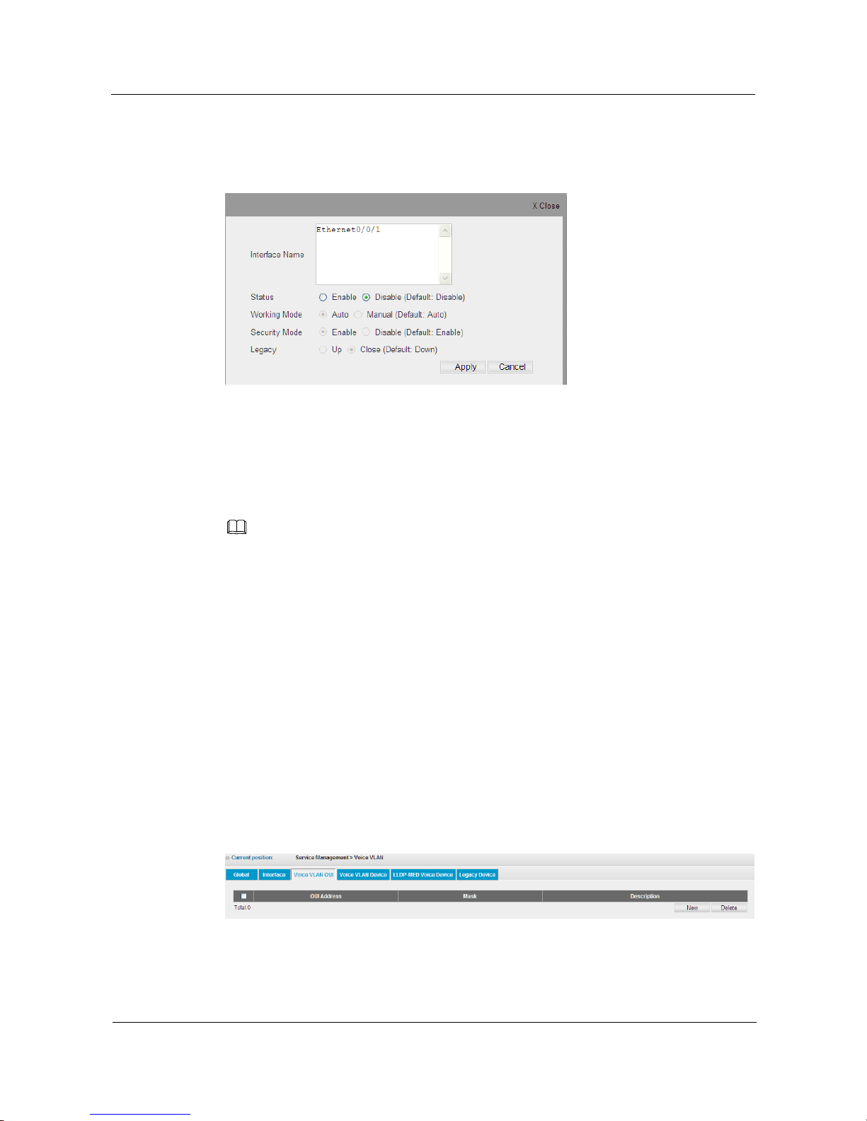
S1700 Managed Series Ethernet Switches
Web User Manual
5 Service Management
Issue 05 (2012-10-25)
Huawei Proprietary and Confidential
Copyright © Huawei Technologies Co., Ltd.
46
Step 2 Choose the interface number to be configured from the interface list, and then click Configure
button to open the page as shown in following figure.
Figure 5-11 Configure Voice VLAN Interface
Step 3 Set Voice VLAN parameters for interface
Step 4 Click Apply button to apply all the changes made.
----End
NOTE
When Eth-Trunk is used, the Voice VLAN attribute of Eth-Trun interface will follow the principles
below:
1) If Eth-Trunk is created, the Voice VLAN attribute of Eth-Trunk interface is set as default value;
2) If added to Eth-Trunk, the interface will be not displayed in Voice VLAN interface list;
3) If removed from Eth-Trunk,the Voice VLAN attribute of original interface will recover.
5.3.3 Voice VLAN OUI
VoIP device connected to the switch can be identified by Organizational Unique Identifier
(OUI) of manufacturer in the source MAC address of received packets. OUI numbers are
assigned to manufacturers and form the first three octets of device MAC addresses. The MAC
OUI numbers for VoIP equipment can be configured on the switch so that traffic from these
devices is recognized as VoIP.
Click Service Management > Voice VLAN > Voice VLAN OUI page to set Voice VLAN
OUT for switch.
Figure 5-12 Voice VLAN OUI
Page 57
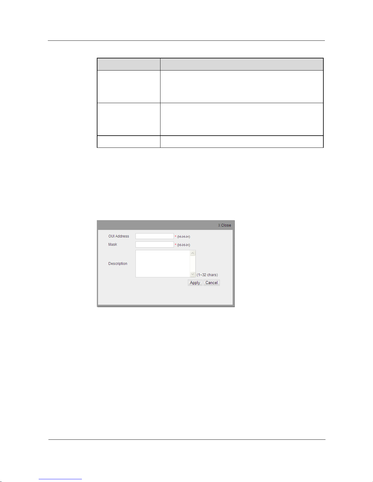
S1700 Managed Series Ethernet Switches
Web User Manual
5 Service Management
Issue 05 (2012-10-25)
Huawei Proprietary and Confidential
Copyright © Huawei Technologies Co., Ltd.
47
Table 5-6 Parameters of Voice VLAN OUI
Item
Description
OUI Address
Specify a MAC address range to add to the list, and the multicast
MAC and broadcast MAC cannot be configured. Enter the MAC
address in format H-H-H. MAC address range is obtained
through Mask and Operation.
Mask
Identify a range of MAC addresses. Selecting a mask of
FFFF-FF00-0000 identifies all devices with the same OUI (the
first three octets). Other masks restrict the MAC address range.
Selecting FFFF-FFFF-FFFF specifies a single MAC address.
Description
User-defined text indicates the name of Voice VLAN device.
Add Voice VLAN OUI
Step 1 Click Service Management > Voice VLAN > Voice VLAN OUI.
Step 2 Click New button to add Voice VLAN OUI to open the page as shown in following figure.
Figure 5-13 Add Voice VLAN OUI
Step 3 Specify OUI MAC address for VoIP device of network in OUI Address field.
Step 4 Enter a MAC address range in Mask field.
Step 5 Add a description for the device in Description field.
Step 6 Click Apply button to apply all the changes made.
----End
5.3.4 Voice VLAN Device
Click Service Management > Voice VLAN > Voice VLAN Device page to view Voice VLAN
device connected to switch, the configuration page is shown as the figure below.
Page 58
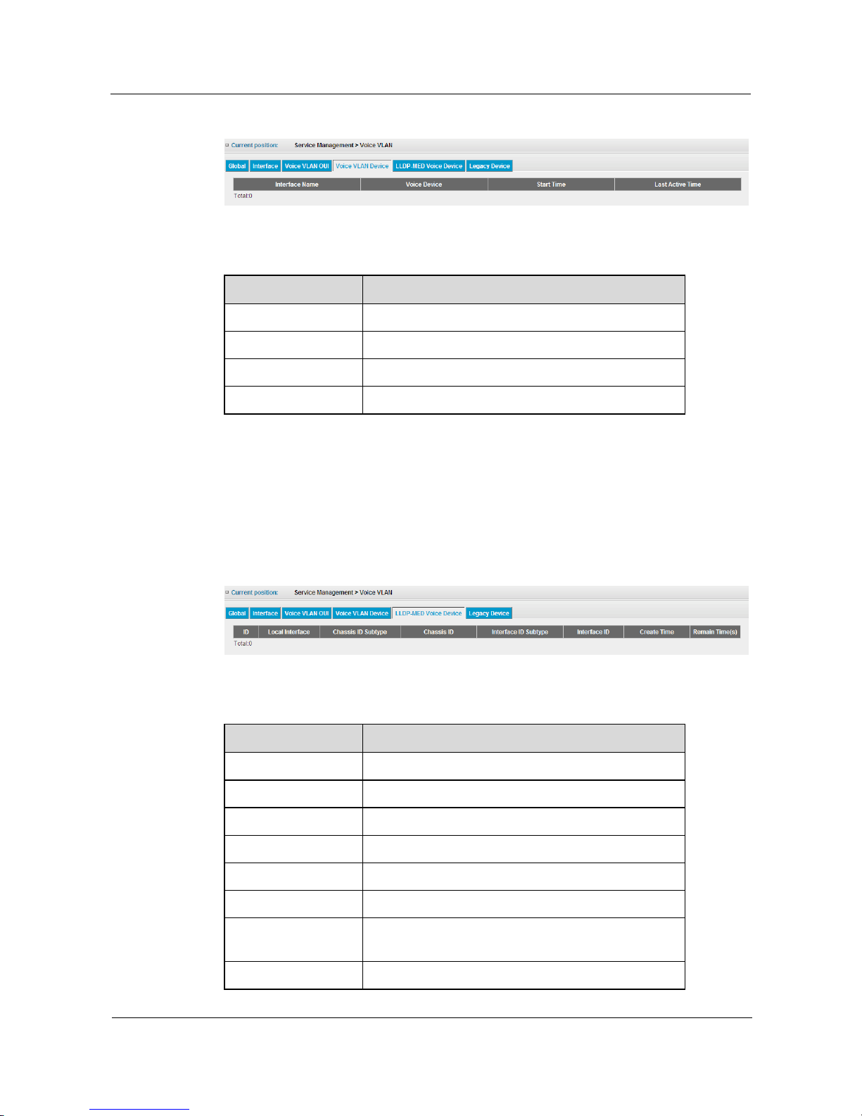
S1700 Managed Series Ethernet Switches
Web User Manual
5 Service Management
Issue 05 (2012-10-25)
Huawei Proprietary and Confidential
Copyright © Huawei Technologies Co., Ltd.
48
Figure 5-14 Voice VLAN Device
Table 5-7 Parameters of Voice VLAN Device
Item
Description
Interface Name
The interface number of Voice device.
Voice Device
OUI address of Voice device.
Start Time
Start time of Voice device.
Last Active Time
Last active time of Voice device.
5.3.5 LLDP-MED Voice Device
Click Service Management > Voice VLAN > LLDP-MED Voice Device page to view voice
device connected to switch through LLDP-MED protocol, the configuration page is shown as
the figure below.
Figure 5-15 LLDP-MED Voice Device
Table 5-8 Parameters of LLDP-MED Voice Device
Item
Description
ID
LLDP-MED device list.
Local Interface
Interface number connected to LLDP-MED device.
Chassis ID Subtype
Chassis subtypes of LLDP-MED device.
Chassis ID
Chassis ID of LLDP-MED device.
Interface ID Subtype
Interface types of LLDP-MED device.
Interface ID
Interface ID of LLDP-MED device.
Create Time
The start time when LLDP-MED device joins the
switch.
Remain Time
The remaining time that LLDP-MED exists on switch.
Page 59
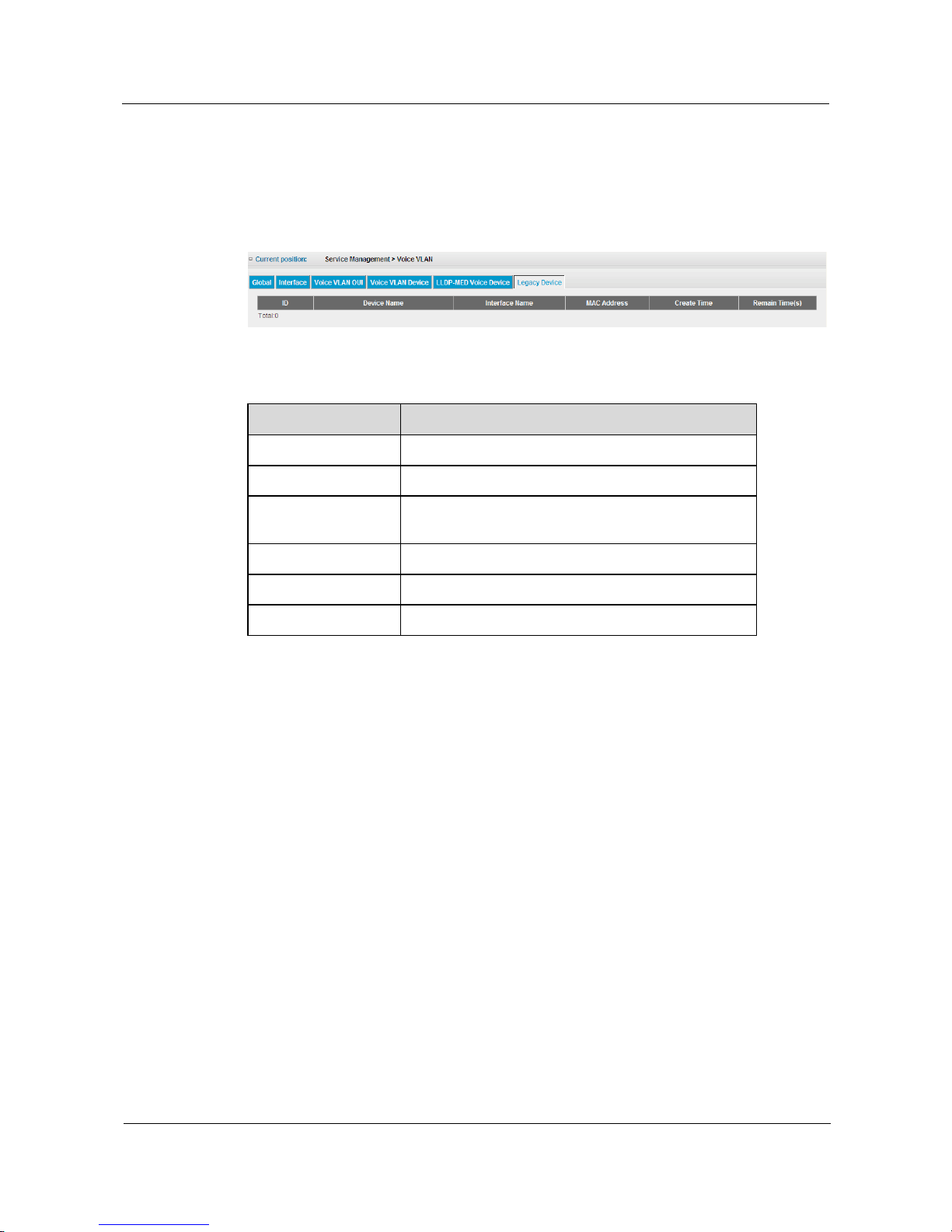
S1700 Managed Series Ethernet Switches
Web User Manual
5 Service Management
Issue 05 (2012-10-25)
Huawei Proprietary and Confidential
Copyright © Huawei Technologies Co., Ltd.
49
5.3.6 Legacy Device
Click Service Management > Voice VLAN > Legacy Device page to view the legacy devices
connected to the switch, the configuration page is shown as the figure below.
Figure 5-16 Legacy Device
Table 5-9 Parameters of Legacy Device
Item
Description
ID
The list number for legacy device.
Device Name
Name of legacy device.
Interface Name
The local interface number communicating to legacy
device.
MAC Address
MAC address of legacy device.
Create Time
The time when message is received from legacy device.
Remain Time
The remaining time that legacy device exists on switch.
5.4 MAC
Ethernet switch uses information of MAC address list to address and forward the message
quickly in link data layer. This article describes the configuring methods of MAC address.
5.4.1 MAC Address Table
MAC Address Table allows checking MAC address forwarding table of switch. If switch
learns a MAC address and its relevant interface number, it will create an entry in forwarding
table. These entries are used in forwarding packets. If the destination address of inbound
traffic is in the database, the packets will be directly forwarded to related interface, or they
will be forwarded to all interfaces.
Click Service Management > MAC > MAC Address Table page to open the page as shown in
following figure, which displays the address list information of switch.
Page 60
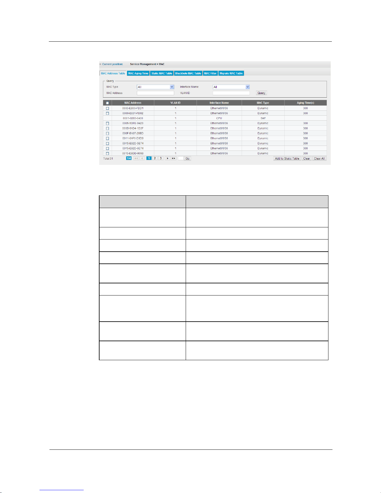
S1700 Managed Series Ethernet Switches
Web User Manual
5 Service Management
Issue 05 (2012-10-25)
Huawei Proprietary and Confidential
Copyright © Huawei Technologies Co., Ltd.
50
Figure 5-17 MAC Address Table
Table 5-10 Parameters of MAC Address Table
Item
Description
Query
Search the matched entry based on MAC Type,
Interface Name, MAC Address or VLAN ID.
MAC Address
The MAC addresses in the address table.
VLAN ID
VLAN ID that corresponds to the above MAC address.
Interface Name
Interface that corresponds to the above MAC address.
MAC Type
The methods that switch discovers MAC address,
which includes Dynamic, Self, Blackhole or Static.
Aging Time
Display the aging time of dynamic MAC address entry.
Add to Static Table
Select the checkbox from the left side of dynamic MAC
address table, and click this button, then you can add the
dynamic MAC address to static address table.
Clear
Click this button and it will delete the learned dynamic
MAC address entry that meets query conditions.
Clear All
Click this button and it will delete all dynamic MAC
addresses from address table.
5.4.2 MAC Aging Time
Use MAC Aging Time to set the remaining time of the learned MAC address in MAC address
forwarding table. If exceeds this time, the switch will discard the MAC address forwarding
records.
Click Service Management > MAC > MAC Aging Time page to view the configuration of
MAC Aging Time.
Page 61
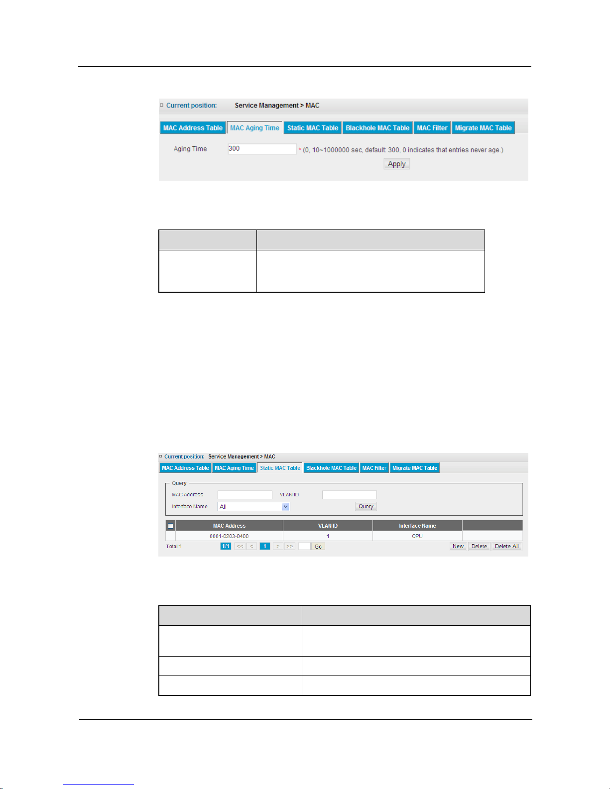
S1700 Managed Series Ethernet Switches
Web User Manual
5 Service Management
Issue 05 (2012-10-25)
Huawei Proprietary and Confidential
Copyright © Huawei Technologies Co., Ltd.
51
Figure 5-18 MAC Aging Time
Table 5-11 Parameters of MAC Aging Time
Item
Description
Aging Time
Enter MAC address aging time.(Range:0, 10~1000000
seconds; default: 300 seconds; 0 means null aging
time).
5.4.3 Static MAC Table
After the MAC address is bound to the assigned interface, the crated static MAC table entry
will not be aging in the address table. If the address is discoverd by another interface, it will
be neglected and not be written into address table. The address will not be learned by other
interfaces unless the static address is deleted manually from address table.
Click Service Management > MAC > Static MAC Table page to open the page as shown in
following figure, which displays the information of static address table of switch.
Figure 5-19 Static MAC Table
Table 5-12 Parameters of Static MAC Table
Item
Description
Query
Search the matched entry based on Interface Name,
MAC Address or VLAN ID.
MAC Address
MAC address in address table.
VLAN ID
VLAN ID that corresponds to the above MAC address
Page 62
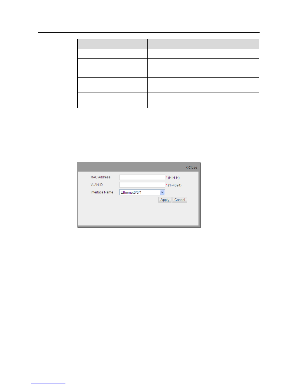
S1700 Managed Series Ethernet Switches
Web User Manual
5 Service Management
Issue 05 (2012-10-25)
Huawei Proprietary and Confidential
Copyright © Huawei Technologies Co., Ltd.
52
Item
Description
Interface Name
Interface that corresponds to the above MAC address.
Edit
Click this button to modify MAC address.
New
Click this button to add a static MAC address entry.
Delete
Click this button to delete static MAC address entry that
is selected from the address table.
Delete All
Click this button to delete all the static MAC addresses
from address table.
Add a Static MAC Address
Step 1 Click New button to add a static MAC address, the configuration page is shown as the figure
below.
Figure 5-20 Add Static MAC Address
Step 2 Enter the static MAC address information to be added in configuration page.
Step 3 Click Apply button to apply all the changes made.
----End
5.4.4 Blackhole MAC Table
Click Service Management > MAC > Blackhole MAC Table page to open the page as shown
in following figure, which displays the information of Blackhole address table on switch.
Page 63
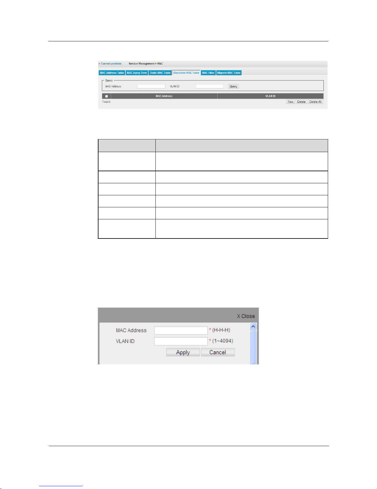
S1700 Managed Series Ethernet Switches
Web User Manual
5 Service Management
Issue 05 (2012-10-25)
Huawei Proprietary and Confidential
Copyright © Huawei Technologies Co., Ltd.
53
Figure 5-21 Blackhole MAC Table
Table 5-13 Parameters of Blackhole MAC Table
Item
Description
Query
Search the matched blackhole address entry in address table through
MAC address and VLAN ID.
MAC Address
MAC address in address table.
VLAN ID
VLAN ID relevant to the above MAC address.
New
Click this button to add a blackhole MAC address.
Delete
Click this button to delete Blackhole MAC address which is selected.
Delete All
Click this button to delete all the Blackhole MAC addresses in
address table.
Add a Blackhole MAC Address
Step 1 Click New button to add a Blackhole MAC address, the configuration page is as shown in
following figure.
Figure 5-22 Add Blackhole MAC
Step 2 Enter the Blackhole MAC address information to be added in configuration page.
Step 3 Click Apply to apply all the changes made.
----End
Page 64
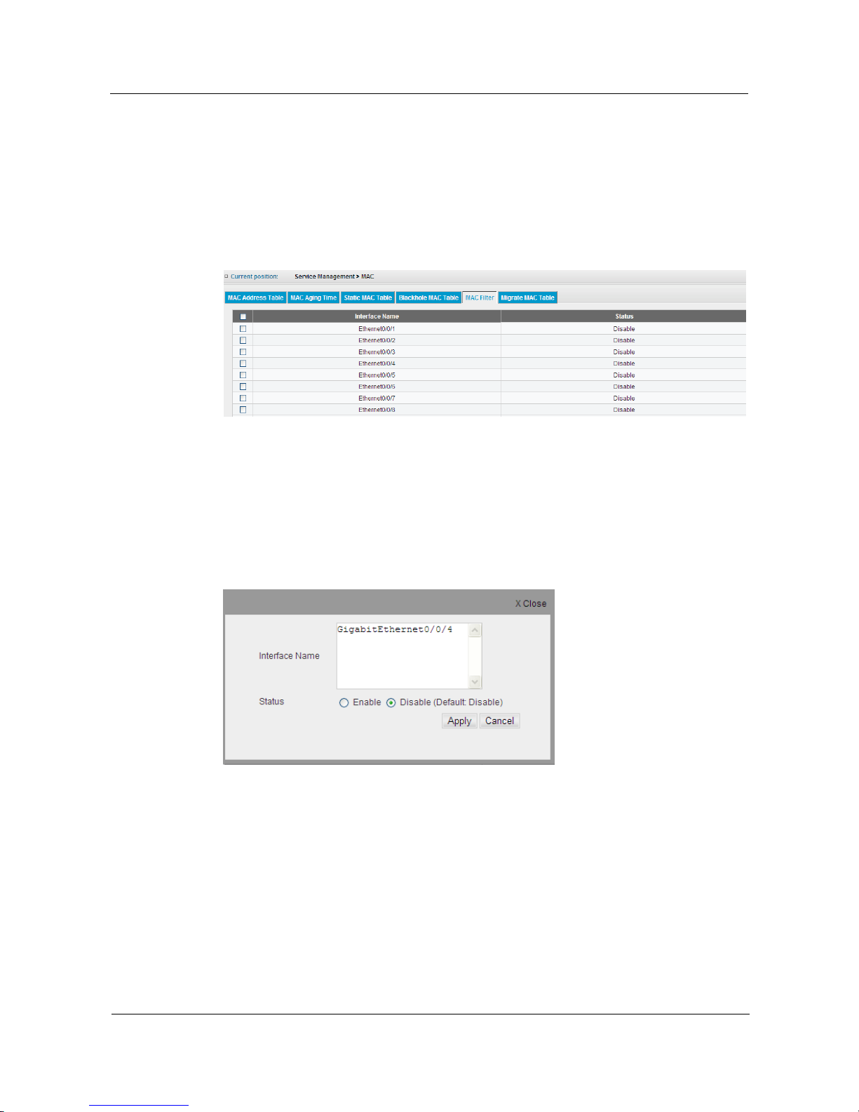
S1700 Managed Series Ethernet Switches
Web User Manual
5 Service Management
Issue 05 (2012-10-25)
Huawei Proprietary and Confidential
Copyright © Huawei Technologies Co., Ltd.
54
5.4.5 MAC Filter
After this function is enabled, only the data of the computer in static MAC address table can
pass through the switch.
Click Service Management > MAC > MAC Filter page to open the page as shown in
following figure, which displays MAC filter status information of all the interfaces
Figure 5-23 MAC Filter
MAC Filter Configuration
Step 1 Choose the check box in the left-hand column of the interface list to be edited, and then click
Configure button to modify the MAC filter function for interface, the configuration page is
shown as the figure below.
Figure 5-24 MAC Filter Configuration
Step 2 Click Enable button to enable MAC filter function of the interface.
Step 3 Click Apply button to apply all the changes made.
----End
5.4.6 Migrate MAC Table
Migrate MAC Table lists the changed information of the same MAC address among the
switch interfaces.
Page 65
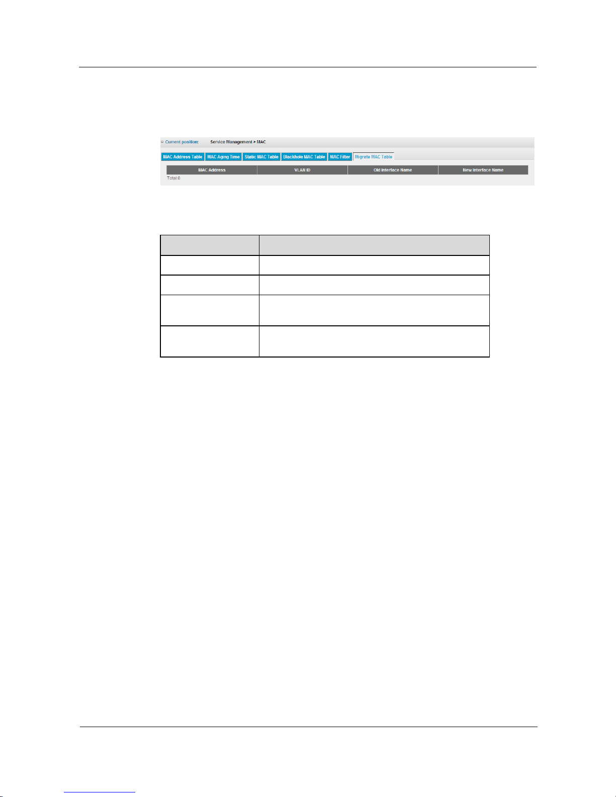
S1700 Managed Series Ethernet Switches
Web User Manual
5 Service Management
Issue 05 (2012-10-25)
Huawei Proprietary and Confidential
Copyright © Huawei Technologies Co., Ltd.
55
Click Service Management > MAC > Migrate MAC Table page to open the page as shown in
following figure, which displays the information of all the MAC address migration
Figure 5-25 Migrate MAC Table
Table 5-14 Parameters of Migrate MAC Table
Item
Description
MAC Address
MAC address in address table.
VLAN ID
VLAN ID that corresponds to the above MAC address
Old Interface Name
The interface number from which the MAC address
migrates.
New Interface Name
The interface number to which the MAC address
migrates.
5.5 STP
Spanning Tree Protocol (STP) is used to decrease link failure in network and provides
protection for network by preventing loop circuit. It is easy to generate unconscious loop
broadcast storm in complex network construction. It is disabled by default. To enable this
function, you must enable STP/RSTP/MSTP function on each switch connected to network.
The switch supports three versions of Spanning Tree Protocol: STP, RSTP and MSTP.
5.5.1 STP Information
Click Service Management > STP > STP Information page to view the STP instance
information on the switch, as shown in the following figure
Page 66
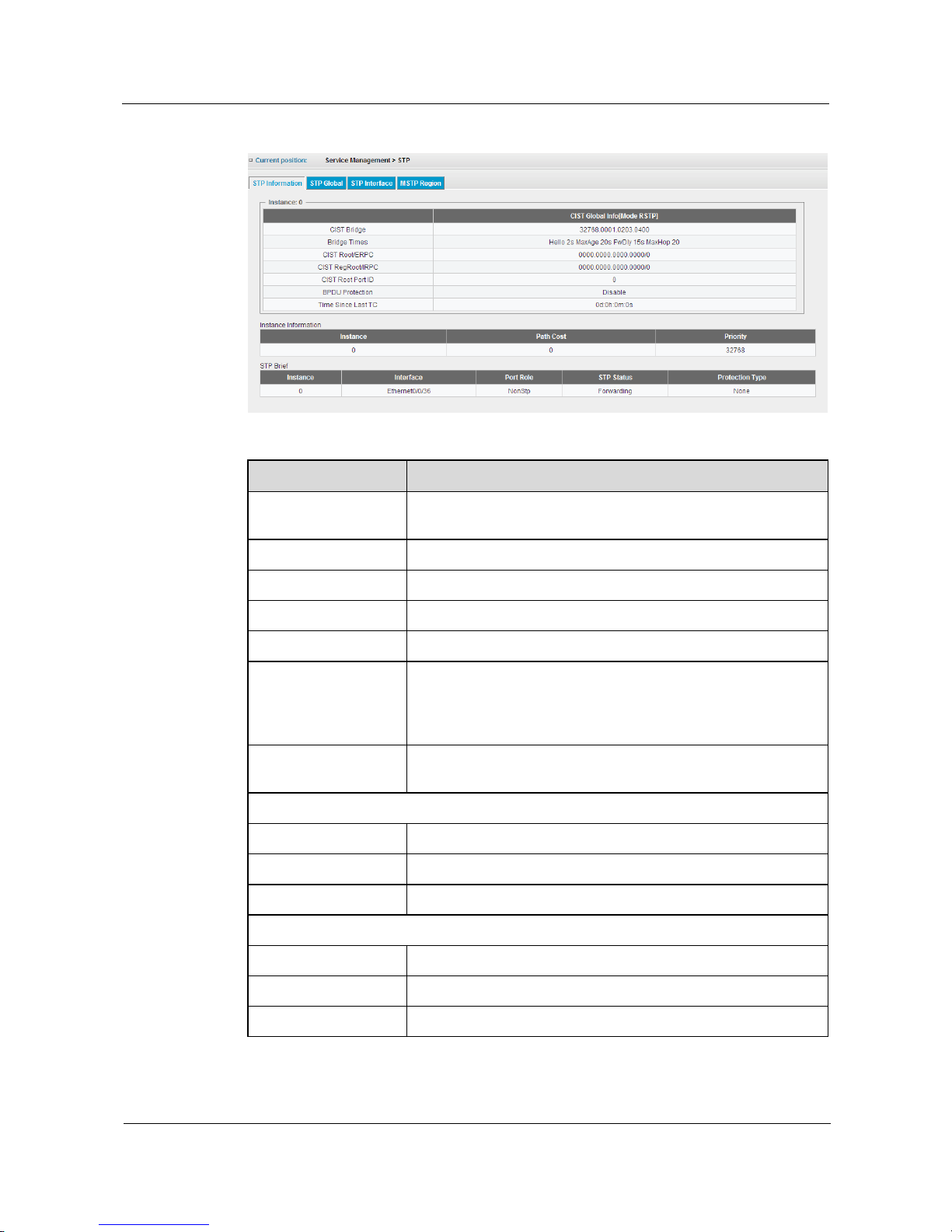
S1700 Managed Series Ethernet Switches
Web User Manual
5 Service Management
Issue 05 (2012-10-25)
Huawei Proprietary and Confidential
Copyright © Huawei Technologies Co., Ltd.
56
Figure 5-26 STP Information
Table 5-15 Parameters of STP Information
Item
Description
CIST Bridge
ID of CIST Bridge consists of priority value of CIST instance and
MAC address of switch.
CIST Bridge Times
Parameter set of timer on device.
CIST root / EPRC
CIST root bridge/external root path cost
CIST RegRoot/ IRPC
CIST RegRoot /internal root path cost
CIST Root Port ID
Interface number of CIST root
BPDU Protection
When BPDU Protection is enabled, the switch will close these
ports and notify the network management system at the same time
if the edge port receives a BPDU. The shut-down port can only be
restored manually by network manager.
Time Since Last TC
The durative period after the spanning tree was configured last
time.
Instance Information
Instance
Instance Number.
Path Cost
Cost value of device path.
Priority
Device priority.
STP Brief
Instance
Instance number.
Interface
Interface number for instance operation.
Port Role
Interface status.
Page 67

S1700 Managed Series Ethernet Switches
Web User Manual
5 Service Management
Issue 05 (2012-10-25)
Huawei Proprietary and Confidential
Copyright © Huawei Technologies Co., Ltd.
57
Item
Description
STP Status
Display this interface's status on the spanning tree:
Discarding: port receives STP configuration messages, but does
not forward packets.
Learning: port does not forward packets, and starts to learn MAC
address.
Forwarding: port forwards packets, and continues learning
addresses.
Protection Type
Options of protection types enabled on interfaces are:
Root protection: root protection function can protect the root
switch position by maintaining the role of designated port. By
configuring the Root Protection on port, all the port roles in
instances will be kept as designated ports. When the port receives a
higher priority BPDU, the port role will not set as non-designated
port, but turn into the listening state and stop forwarding packets.
If the port has no longer receives higher priority BPDU after a long
time, it will restore to its original normal state.
Loop Protection: on the switch, the status of root ports and other
blocked ports are relying on the continuous BPDUs received from
the upstream switch. The switch will reselect root port when the
BPDU from the upper switch cannot be received because of
network congestion or unidirectional link failure. If the original
root port becomes a designated port and the original blocked port
moves to the forwarding state, it will results in undesirable loops in
switch network. Loop protection function can suppress this kind of
loop. After the loop protection started, if the root port cannot
receive a BPDU from upstream, it will be set in blocked state, and
the blocked ports will remain in blocking state and does not
forward packets to the network to ensure that no loop can be
formed.
TC Protection: the switch will delete MAC address table and ARP
table entry if TC-BPDU is received. The frequent deletion of table
entry for receiving a large amount of TC-BPDU will bring a great
burden to device. TC protection Configuration on interface can
avoid frequent deletion operations, and avoid the transmission of
TC-BPDU.
5.5.2 STP Global
Click Service Management > STP > STP Global page to configure the STP global parameters
for the switch, the configuration page is shown as the figure below.
Page 68
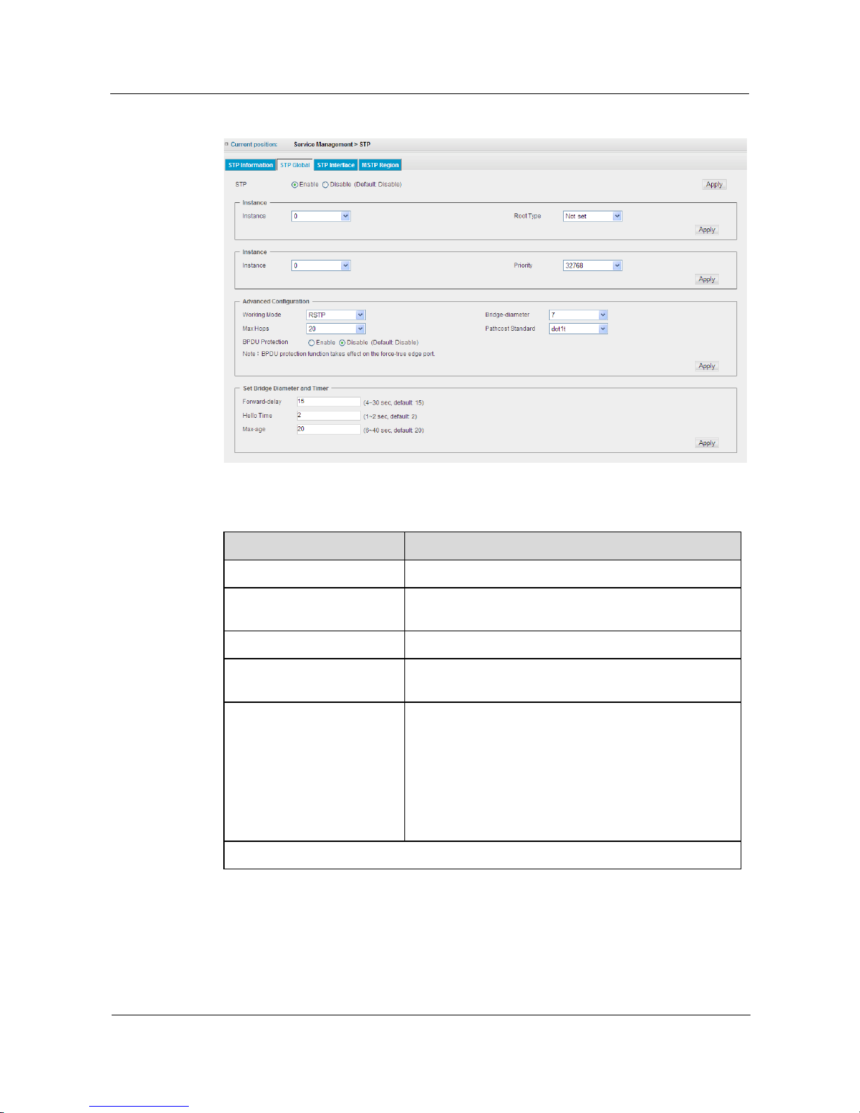
S1700 Managed Series Ethernet Switches
Web User Manual
5 Service Management
Issue 05 (2012-10-25)
Huawei Proprietary and Confidential
Copyright © Huawei Technologies Co., Ltd.
58
Figure 5-27 STP Global Settings
Table 5-16 Parameters of STP Global Settings
Item
Description
STP
Enable or disable STP on this switch(default: disable)
Instance
Select instance number for the root types needed to
configure.
Root Type
The options for root type: Not set, Primary and Secondary.
Instance
Select instance number for priority value needed to
configure.
Priority
Bridge priority is used in selecting the root device. The
device with the highest priority (the smaller value the
higher priority) becomes the STP root device. However, if
all devices have the same priority, the device with the
lowest MAC address will then become the root device
(note that lower numeric values indicate higher
priority) .Default value: 32768; Range: 0~61440; Step
Length: 4096.
Advanced Configuration
Page 69

S1700 Managed Series Ethernet Switches
Web User Manual
5 Service Management
Issue 05 (2012-10-25)
Huawei Proprietary and Confidential
Copyright © Huawei Technologies Co., Ltd.
59
Item
Description
Working Mode
Specify types of spanning tree adopted on this switch.
STP: select this parameter to set global spanning tree
protocol on switch (STP).
RSTP: select this parameter to set global rapid spanning
tree protocol on switch (RSTP).
MSTP: select this parameter to set global multiple
spanning tree protocol on switch (MSTP).
Bridge-diameter
Bridge-diameter: 2-7, in step of 1, calculate the default
Forward Delay, Hello Timer, Max-Age based on the
different Network-diameter.
Max Hops
Set the device hops among the devices within spanning
tree regions before the BPDU packets are discarded by the
switch. The number of hop will be reduced one when each
packet passes through the switch until the hop count to
zero. At this point, the switch will discard the BPDU
packet, and interface information in packet will be
time-out. Value ranges from 6 to 40, default is 20.
Pathcost Standard
Choose the standard of path cost calculation. The options
are as follow: dot1t, dot1d-1998 and legacy.
BPDU Protection
Under normal circumstances, the edge interface will not
receive a BPDU. If someone attacks device maliciously
with fake BPDU, the switch will automatically set the
edge interface to non-edge interface and re-calculate
spanning tree to avoid network jitter when the edge
interface receives BPDU. When BPDU protection
function is enabled on switch, the edge interface will be
shutdown when receiving the BPDU, but the properties of
the edge interface will be the same. At the same time, the
network management system will be notified. The
shutdown edge port can only be restored by network
manager manually (the default is Disable).
Set Bridge Diameter and Timer
Forward-delay
The setting range is 4-30 seconds (default: 15sec). Each
interface on the switch needs to wait double of
forward-delay time when the blocked status changes to
forwarding status.
Hello Time
Interval for root bridge's broadcast “hello” message.
“hello” message is used to detect whether the network
topology is normal or not.
Page 70
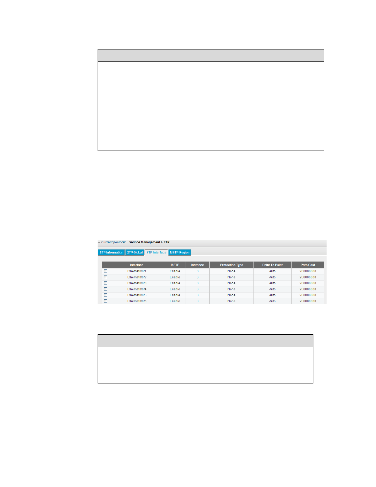
S1700 Managed Series Ethernet Switches
Web User Manual
5 Service Management
Issue 05 (2012-10-25)
Huawei Proprietary and Confidential
Copyright © Huawei Technologies Co., Ltd.
60
Item
Description
Max-age
Max-age ensures that the old information will not be
endlessly circled within the network's redundant path, and
thus stop the valid transmission of the new information.
The value is set by the root bridge to confirm that the
spanning tree configuration value of the switch accords
with the other devices on the bridge LAN. If the value is
timeout, while the switch has not received the BPDU
packet from root bridge, the switch starts to send its BPDU
to all the other switches to ask for becoming the root
bridge. If the switch has the minimal bridge identifier, it
will become root bridge. User can set the value from 6-40
seconds, the default is 20 seconds.
5.5.3 STP Interface
Click the Service Management > STP > STP Interface page to configure attributes for specific
interfaces, including port priority, path cost, protection type, and edge port. You may use a
different priority or path cost for ports of the same media type to indicate the preferred path.
Different link type indicates a point-to-point connection or shared-media connection, and
different edge port indicates that the attached device can support fast forwarding.
Figure 5-28 STP Interface
Table 5-17 Parameters of STP Interface
Item
Description
Interface
Interface number.
MSTP
Enable/disable STP on this interface.
Instance
The instance numbers that runs on interface.
Page 71

S1700 Managed Series Ethernet Switches
Web User Manual
5 Service Management
Issue 05 (2012-10-25)
Huawei Proprietary and Confidential
Copyright © Huawei Technologies Co., Ltd.
61
Item
Description
Protection Type
Whether to enable the appropriate protection on interface. The
options are as follow:
Root protection: root protection function can protect the root
switch position by maintaining the role of designated port. By
configuring the Root Protection on port, all the port roles in
instances will be kept as designated ports. When the port receives a
higher priority BPDU, the port role will not be set as
non-designated port, but turn into the listening state and stop
forwarding packets. If the port has no longer receives higher
priority BPDU after a long time, it will restore to its original
normal state.
Loop Protection: on the switch, the status of root ports and other
blocked ports are relying on the continuous BPDUs received from
the upstream. The switch will reselect root port when the BPDU
from the upper switch can not be received because of network
congestion or unidirectional link failure. If the original root port
becomes a designated port and the original blocked port moves to
the forwarding state, it will results in undesirable loops in Switch
network. Loop protection function can suppress this kind of loop.
After the loop protection started, if the root port can not receive a
BPDU from upstream, it will be set in blocked state, and the
blocked ports will remain in blocking state and does not forward
packets to the network to ensure that no loop can be formed.
TC Protection: the switch will delete MAC address table and ARP
table entry if TC-BPDU is received. The frequent deletion of table
entry for receiving a large amount of TC-BPDU will bring a great
burden to device. TC protection Configuration on interface can
avoid frequent deletion operations, and will avoid the transmission
of TC-BPDU.
Point to Point
force-true: indicate a point-to-point share link. Point-to-point
interface is similar to the edge interface, but the point-to-point
interface mode must be full-duplex mode. Like the edge interface,
the point-to-point interface can transform to forwarding state
quickly in order to gain the advantages of RSTP.
force-false: indicate the interface does not have a point-to-point
state.
auto: indicate the interface will transform to point-to-point state
whenever it can be transformed, just as the point-to-point state
"force-true" . If the interface cannot remain in this state (for
example, the interface was forced to run half-duplex mode), the
state will be changed, just as the state of "force-false". The default
parameter is set to "auto".
Path Cost
The associated cost for interface that forwards the packet to the
designated interface list.
Parameters of Editing STP Interface “GigabitEthernet 0/0/1
Step 1 Click Service Management>STP> STP Interface.
Page 72
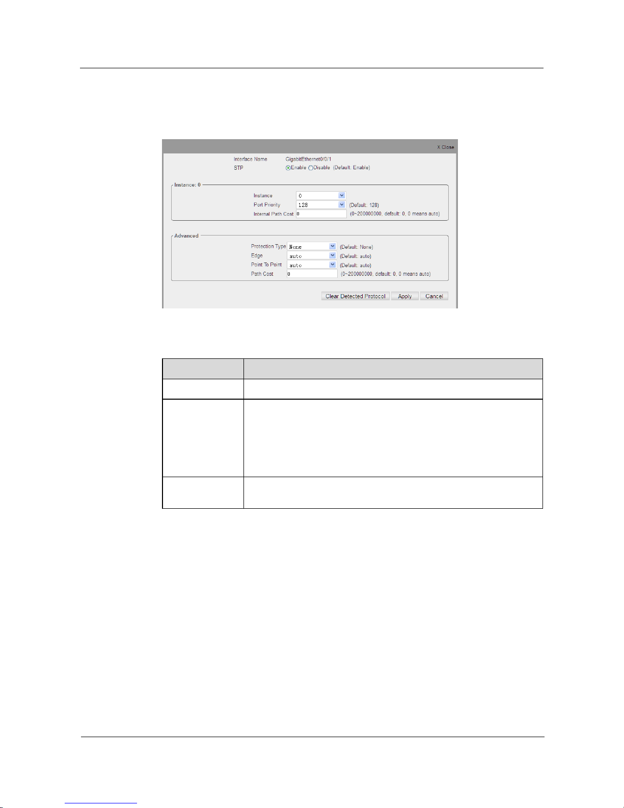
S1700 Managed Series Ethernet Switches
Web User Manual
5 Service Management
Issue 05 (2012-10-25)
Huawei Proprietary and Confidential
Copyright © Huawei Technologies Co., Ltd.
62
Step 2 Select checkbox on the left of interface “GigabitEthernet0/0/1" in interface list and then click
Configure button.The configuration page is shown as below.
Figure 5-29 STP Settings Based on Interface
Table 5-18 Parameters of STP Settings Based on Interface
Item
Description
Instance
Select instance number on interface.
Port Priority
Definition of this interface‟s priority in spanning tree. A higher priority
will specify firstly interface to forwarding packet. The lower number
indicates the higher priority. If all interfaces‟ path cost is the same on
this switch, the higher priority interface will be configured as the active
link in the spanning tree. The default value is 128; range is 0~240; field
is 16.
Internal Path
Cost
The root cost when switch reaching to CIST region.
Page 73

S1700 Managed Series Ethernet Switches
Web User Manual
5 Service Management
Issue 05 (2012-10-25)
Huawei Proprietary and Confidential
Copyright © Huawei Technologies Co., Ltd.
63
Item
Description
Protection Type
The options for whether to enable corresponding protection on interface
are:
Root protection: Root protection function protects root switch‟s location
through maintaining specified port role. Port configured to Root
protection function, all of its port value on instance is maintained as
specified port. When a port receives a higher priority BPDU, the port
role won't change into non-specified port; otherwise it changes into
detecting status, forwarding no message. In a long enough periods, if a
port receives no higher BPDU any more, the port will recover to its
previous normal status.
Loop circuit protection: on switch, status of root ports and other
blocking ports is maintained by continually receiving BPDU from up
streaming switch. When these ports receive no BPDU from up
streaming switch by causes of link congestions or one-way link failures,
the switch will select root ports again. The previous root ports will turn
to specified ports and previous congestion ports will shift to forwarding
status, thus causing loop circuit in exchanging network. Loop circuit
protection function will restrain such occurrence. When enabling loop
circuit protection function, the root ports will be set to blocking status if
these ports can not receive BPDU from upstream, while the blocking
ports will remain blocking status, forwarding no message and thus
causing no loop circuit in network.
TC protection:when switch receiving TC-BPDU, it will implement
delete operation of MAC address table and APR table. If receiving
frequently TC-BPDU to conduct table delete action, it will be
overburdened for the device. After configuring topology change
protection on interface, the frequent delete operation can be avoided and
the transmitting TC-BPDU can be avoid as well.
Edge
“force-true” specifies ports as edge ports. The edge ports connect
directly to terminal, affecting no network‟s connectivity, thus getting
quickly into Forwarding status. When edge ports receiving
configuration message (BPDU Message), the system will automatically
set these ports as non-edge ports and calculate spanning tree, causing
network‟s topology oscillation.
Point to Point
Force-true: it represents point to point sharing link. Point to point port is
similar to edge port, but point to point mode must be full duplex mode.
As the edge port, point to point port can quickly turn into forwarding
status to obtain RSTP advantages.
Force-false: it represents this interface does not own point to point
status.
auto: it represents that interface will change into point to point status
whenever it is possible, like status of point to point is “force-true”. If the
interface cannot maintain this status, (like interface is forced operating
half duplex mode), the point to point status will be changed, like status
of point to point is “force-false”. This parameter default is set as “auto”.
Path Cost
Cost of this interface to CIST root path.
Page 74
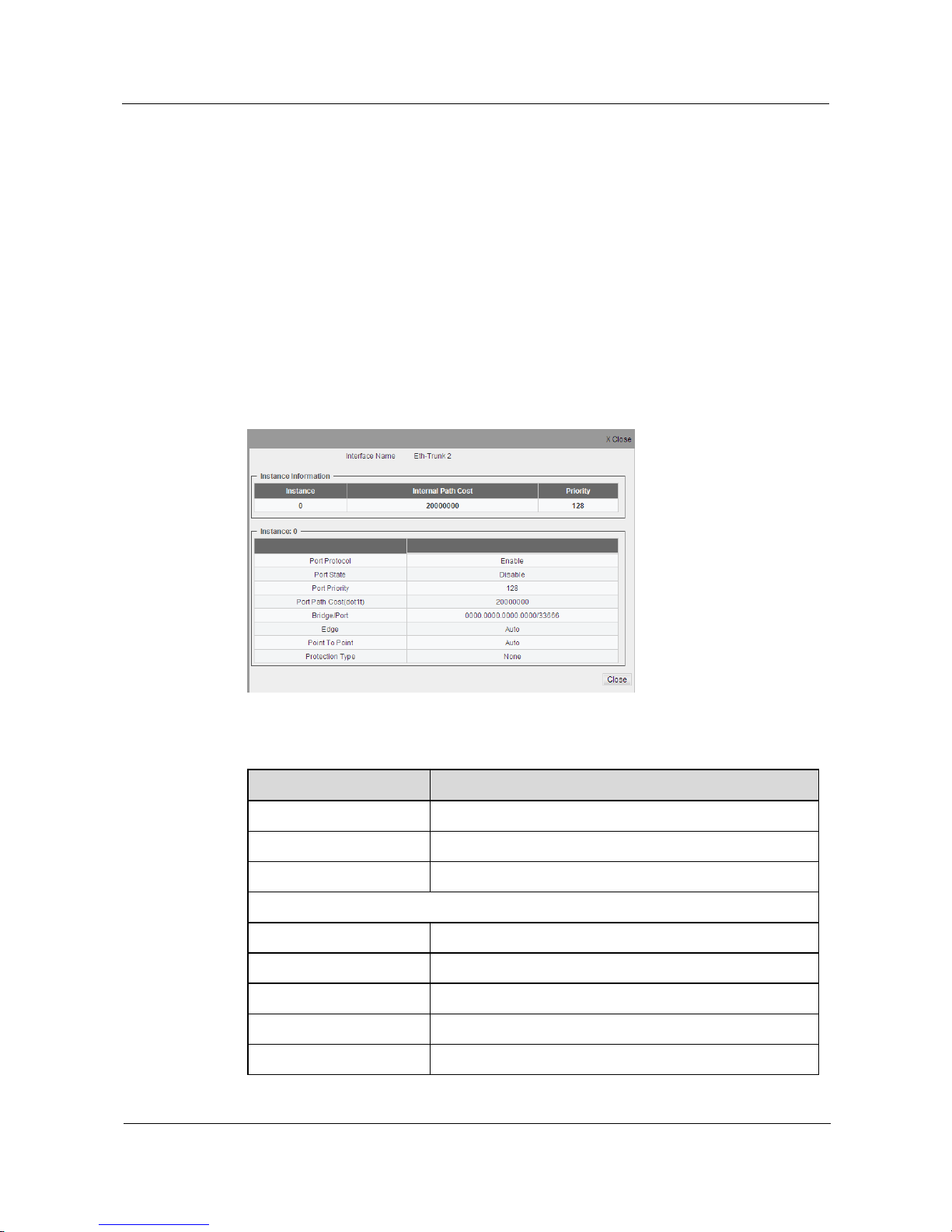
S1700 Managed Series Ethernet Switches
Web User Manual
5 Service Management
Issue 05 (2012-10-25)
Huawei Proprietary and Confidential
Copyright © Huawei Technologies Co., Ltd.
64
Step 3 Modify the needed parameter
Step 4 Click Apply button to apply all the changes made.
----End
View STP Interface Details
Step 1 Click Service Management>STP> STP Interface.
Step 2 Select the checkbox on the left side of interface in interface list and click Detail Info button,
displaying the specified interface details of STP configuration information; the configuration
page is shown as the figure below.
----End
Figure 5-30 Display STP Interface Details
Table 5-19 Parameters STP Interface Details
Item
Description
Instance
Instance number.
Internal Path Cost
This interface‟s internal path cost.
Priority
This interface‟s priority.
Instance
Port Protocol
Whether to enable STP protocol on interface.
Port State
Interface‟s STP status.
Port Priority
This interface‟s priority.
Port Path Cost
This interface‟s internal path cost.
Bridge Port
Bridge ID number/interface priority.
Page 75

S1700 Managed Series Ethernet Switches
Web User Manual
5 Service Management
Issue 05 (2012-10-25)
Huawei Proprietary and Confidential
Copyright © Huawei Technologies Co., Ltd.
65
Item
Description
Edge
“force-true” specifies ports as edge ports. The edge ports
connect directly to terminal, affecting no network‟s
connectivity, thus getting quickly into Forwarding status.
When edge ports receiving configuration message (BPDU
Message), the system will automatically set these ports as
non-edge ports and calculate spanning tree, causing
network‟s topology oscillation.
Point to Point
Force-true: it represents point to point sharing link. Point to
point port is similar to edge port, but point to point mode
must be full duplex mode. As the edge port, point to point
port can quickly turn into forwarding status to obtain RSTP
advantages.
Force-false: it represents this interface does not own point to
point status.
auto: it represents that interface will change into point to
point status whenever it is possible, like status of point to
point is “force-true”. If the interface can not maintain this
status,(like interface is forced operating half duplex mode),
the point to point status will be changed, like status of point
to point is “force-false”. This parameter default is set as
“auto”.
Page 76

S1700 Managed Series Ethernet Switches
Web User Manual
5 Service Management
Issue 05 (2012-10-25)
Huawei Proprietary and Confidential
Copyright © Huawei Technologies Co., Ltd.
66
Item
Description
Protection Type
The options for whether enable corresponding protection on
interface are:
Root protection: Root protection function protects root
switch‟s location through maintaining specified port role.
Port configured to Root protection function, all of its port
value on instance is maintained as specified port. When a
port receives a higher priority BPDU, the port role won't
change into non-specified port; otherwise it changes into
detecting status, forwarding no message. In a long enough
periods, if a port receives no higher BPDU any more, the port
will recover to its previous normal status.
Loop circuit protection: On switch, status of root ports and
other blocking ports is maintained by continually receiving
BPDU from up streaming switch. When these ports receive
no BPDU from up streaming switch by causes of link
congestions or one-way link failures, the switch will select
root ports again. The previous root ports will turn to specified
ports and previous congestion ports will shift to forwarding
status, thus causing loop circuit in exchanging network. Loop
circuit protection function will restrain such occurrence.
When enabling loop circuit protection function, the root ports
will be set to blocking status if these ports can not receive
BPDU from upstream, while the blocking ports will remain
blocking status, forwarding no message and thus causing no
loop circuit in network.
TC protection:When switch receiving TC-BPDU, it will
implement delete operation of MAC address table and APR
table. If receiving frequently TC-BPDU to conduct table
delete action, it will be overburdened for the device. After
configuring topology change protection on interface, the
frequent delete operation can be avoided and the transmitting
TC-BPDU can be avoid as well.
NOTE
When Eth-Trunk is used, the STP attribute of Eth-Trunk interface will follow the principles below:
1) If Eth-Trunk is created, the STP attribute of Eth-Trunk interface is set as default value;
2) If added to Eth-Trunk, the interface will be not displayed in STP interface list;
If removed from Eth-Trunk,the STP attribute of original interface will recover.
5.5.4 MSTP Region
Click Service Management>STP>MSTP Region to view switch's domain information; the
configuration page is shown as the figure below.
Page 77
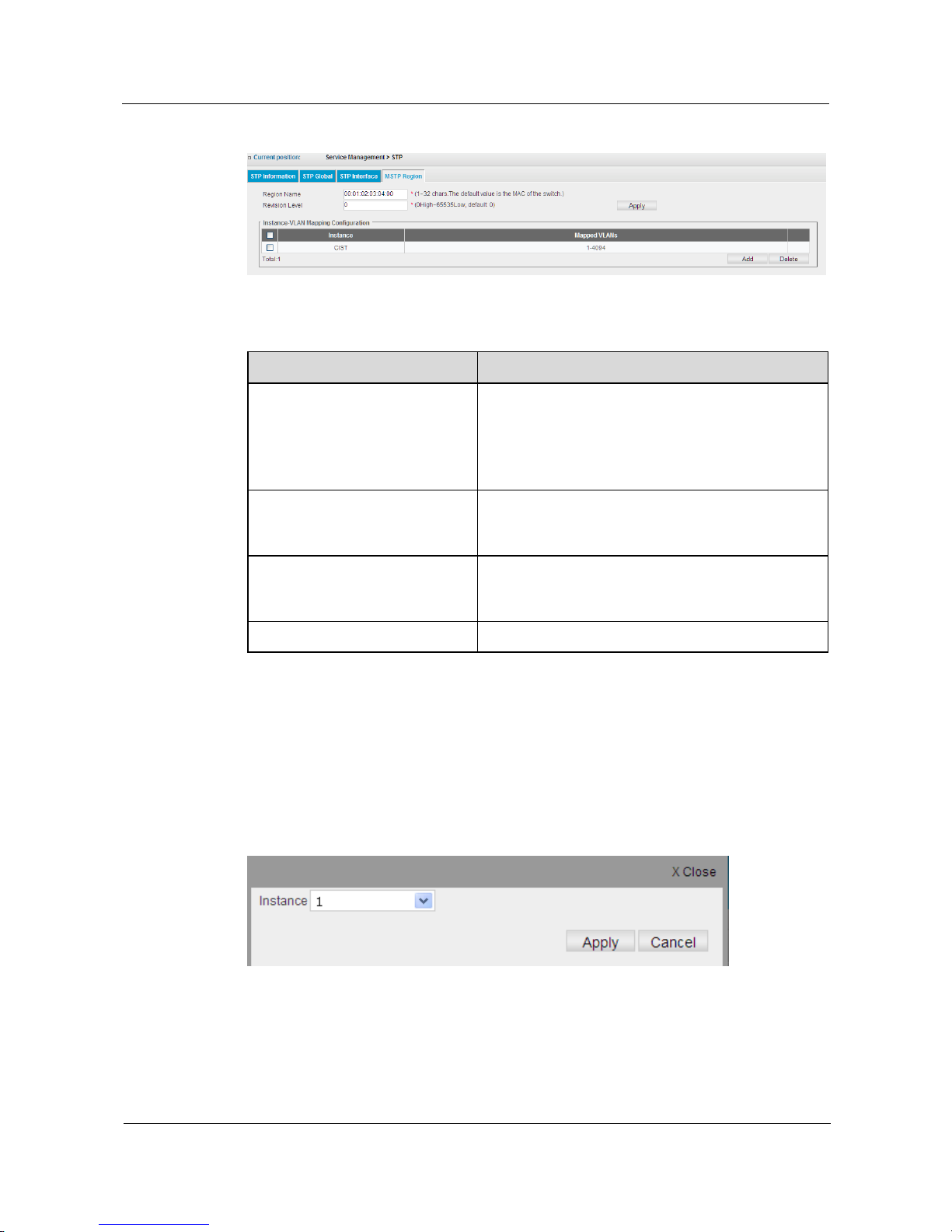
S1700 Managed Series Ethernet Switches
Web User Manual
5 Service Management
Issue 05 (2012-10-25)
Huawei Proprietary and Confidential
Copyright © Huawei Technologies Co., Ltd.
67
Figure 5-31 STP Region Information
Table 5-20 Parameters of MSTP Region
Item
Description
Region Name
Specify MST domain name joined by the switch; the
domain name can only identify MSTI (Multiple
Spanning Tree Instance).
If domain name is not set, the MAC address of the
device operating MSTP will be displayed.
Revision Level
This value and domain name altogether identifies the
MSTP protocol configured on switch. The value range
is 0~65535; default is 0.
Instance
Display the MST instance ID currently configured on
switch. The default CIST is common and internal
spanning tree of MSTI.
Mapped VLANs
Display VLAN ID mapped to specified MST instance.
Add MSTP Instance
Step 1 Click Service Management>STP>MSTP Region.
Step 2 Click Add button to create a new MSTP Region, the configuration is shown as the figure
below.
Figure 5-32 Add CIST
Step 3 Select the instance number needed to add in Instance bar.
Step 4 Click Apply button to apply all the changes made.
----End
Page 78
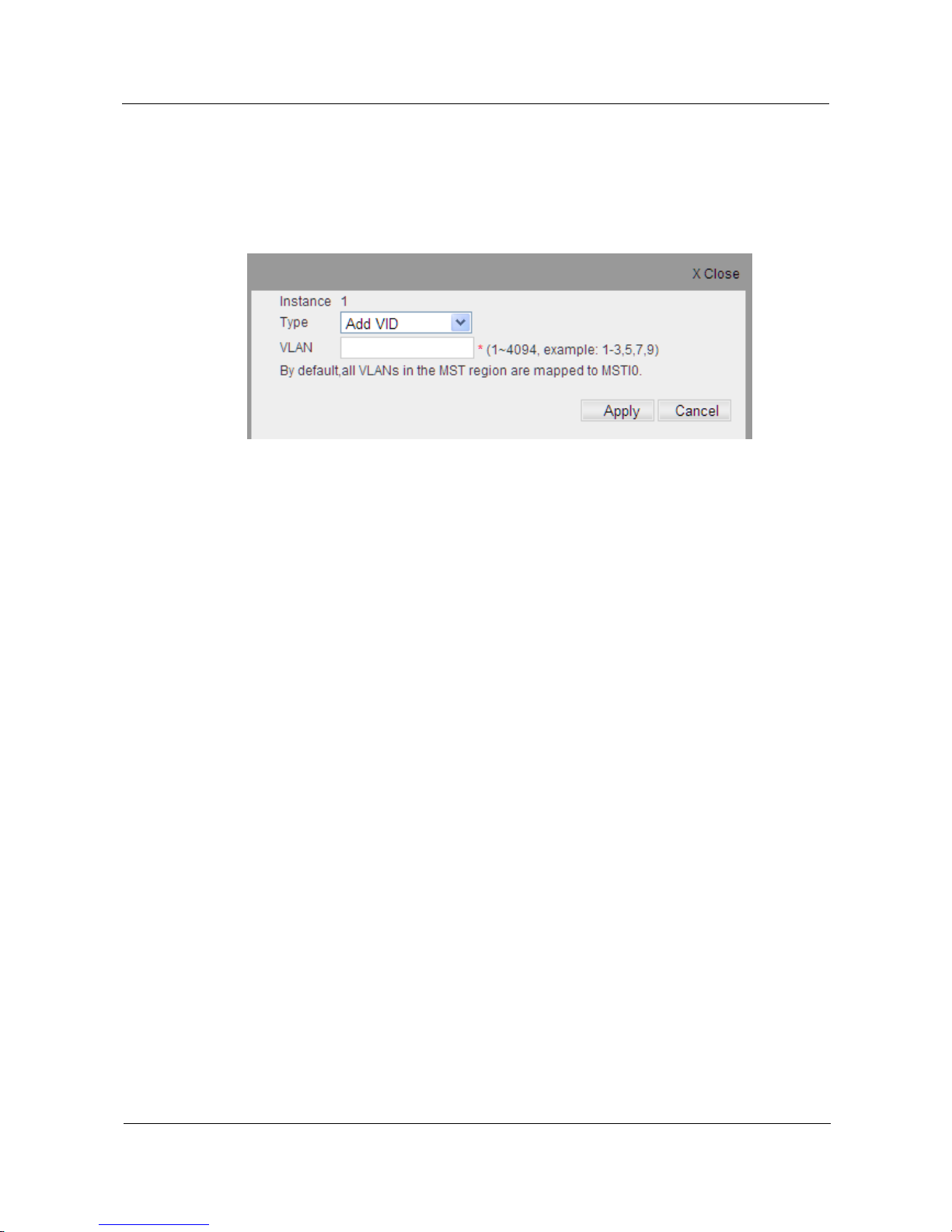
S1700 Managed Series Ethernet Switches
Web User Manual
5 Service Management
Issue 05 (2012-10-25)
Huawei Proprietary and Confidential
Copyright © Huawei Technologies Co., Ltd.
68
Edit MSTP Instance
Step 1 Click Service Management>STP>MSTP Region.
Step 2 Click the edit icon on the left of Instance, the configuration page is shown as the figure below.
Figure 5-33 Edit CIST
Step 3 In Type pull down menu, select VLAN to add/remove instance.
Step 4 In VLAN bar, enter the VLAN ID needed to add/ remove.
Step 5 Click Apply button to apply all the changes made.
----End
5.6 IGMP Snooping
IGMP Snooping (Internet Group Management Protocol Snooping) is multicast management
and control mechanism working on 2-layer Ethernet switch.
After IGMP Snooping is enabled, switch establishes mapping relationship for switch's
interface and multicast address through snooping IGMP message received on the interface,
forwarding multicast data stream according to the established mapping relationship. The
multicast data stream received on the switch will be flooding in VLAN when IGMP Snooping
is disabled.
IGMP Snooping supports link aggregation. If Ethernet port belong to trunk group, the
Ethernet port‟s IGMP snooping configuration can‟t take effect; when Ethernet port leave trunk
group, the Ethernet port‟s IGMP Snooping configuration will take effect.
5.6.1 Global
Click Service Management>IGMP Snooping>Global to check switch‟s IGMP Snooping
global configuration information; the configuration page is shown as the figure below.
Page 79
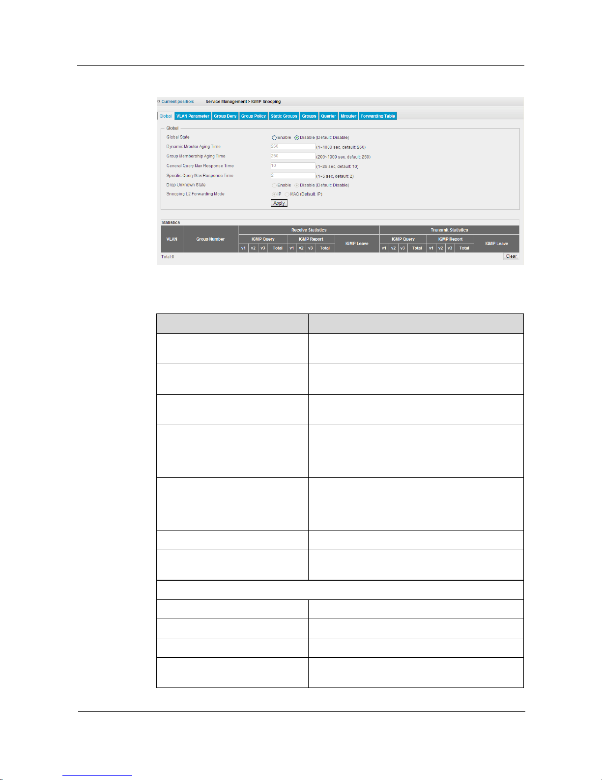
S1700 Managed Series Ethernet Switches
Web User Manual
5 Service Management
Issue 05 (2012-10-25)
Huawei Proprietary and Confidential
Copyright © Huawei Technologies Co., Ltd.
69
Figure 5-34 IGMP Snooping Global Settings
Table 5-21 Parameters of IGMP Snooping Global Setting
Item
Description
Global State
Select enabling or disabling IGMP Snooping global
function.
Dynamic Mrouter Aging Time
Configure the aging time globally for multicast
router interface.
Group Membership Aging Time
Configure the aging time globally for member
interface.
General Query Max Response Time
The maximum amount of time before sending IGMP
response message when the host receives general
query packet. The range is 1-25 seconds, and the
default is 10 seconds.
Specific Query Max Response Time
The maximum amount of time before sending IGMP
response message when the host receives specific
query packet. The range of permissible time is 1-5
seconds, and the default is 2 seconds.
Drop Unknown State
Whether to drop the unknown multicast data stream.
Snooping L2 Forwarding Mode
Set forwarding mode for multicast. The default is IP
mode.
Statistical Table
VLAN
VLAN ID number.
Group Number
The number of multicast group learned in VLAN.
IGMP Query
The number of received/sent IGMP query message
IGMP Report
The number of received/sent report message of IGMP
member
Page 80
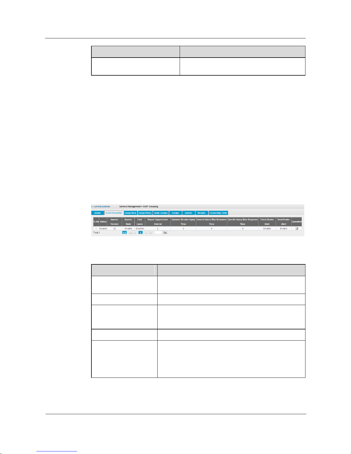
S1700 Managed Series Ethernet Switches
Web User Manual
5 Service Management
Issue 05 (2012-10-25)
Huawei Proprietary and Confidential
Copyright © Huawei Technologies Co., Ltd.
70
Item
Description
IGMP Leave
The number of received/sent IGMP leave multicast
group message
Configure Global Parameter of IGMP Snooping
Step 1 Click Service Management>IGMP Snooping>Global.
Step 2 Enabling “Global State”.
Step 3 Click Apply to apply all the changes made.
----End
5.6.2 VLAN Parameter
Click Service Management>IGMP Snooping >VLAN Parameter to view IGMP Snooping
configuration information of VLAN; the configuration page is shown as the figure below.
Figure 5-35 IGMP Snooping VLAN
Table 5-22 Parameters of IGMP Snooping VLAN
Item
Description
VLAN
Used to identify the VLAN configuration to IGMP Snooping
function.
Status
Whether to enable IGMP Snooping function.
Querier Version
The version is compatible with other devices on Internet. The
switch uses this IGMP version to send IGMP common group
query message.
Querier State
Enable or disable transmitting IGMP query protocol packets.
Fast Leave
Used to configure fast leave function for multicast members on
VLAN. After enabling it, the switch receives an IGMP Leave
Packet, this function will allow multicast members to leave the
group immediately (the switch does not need to send IGMP
specific group query).
Page 81
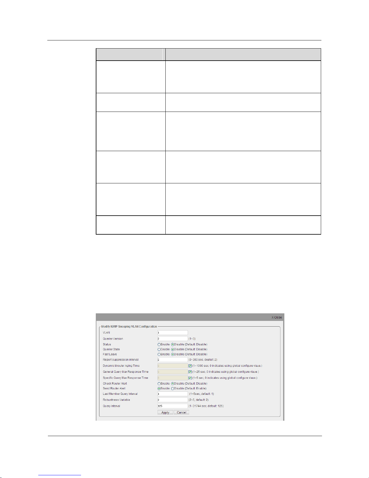
S1700 Managed Series Ethernet Switches
Web User Manual
5 Service Management
Issue 05 (2012-10-25)
Huawei Proprietary and Confidential
Copyright © Huawei Technologies Co., Ltd.
71
Item
Description
Report Suppression
interval
IGMP Snooping will hold the message with same content in a
certain time. It supports the suppression to the member
message of IGMPv1, IGMPv2, and IGMPv2 Leave. 0 indicates
disable message suppression function.
Dynamic Mrouter Aging
Time
The aging time for configuring dynamic route; 0 represent the
aging time of dynamic route with global configuration.
General Query Max
Response Time
The maximum permissible time of the host sending IGMP
response message after receives general group query. The
range of permissible time is 1-25 seconds, and the default is 10
seconds. 0 indicates maximum response time of general group
with global settings.
Specific Query Max
Response Time
The maximum permissible time of the host sending IGMP
response message after receives specific group query. The
range of permissible time is 1-5 seconds. 0 indicates maximum
response time of specified group with global settings.
Check Router Alert
Check the Router-Alert options in IGMP message header; if
use this function, then IGMP message‟s IP head received by the
current VLAN must be attached to Router Alert (IGMPv1
message excluded), otherwise drop this message.
Send Router Alert
Router-Alert option includes whether to send router alert in
IGMP message header.
Set the parameters of Snooping VLAN
Step 1 Click Service Management>IGMP Snooping >VLAN Parameter.
Step 2 Click the Edit icon on the right of VLAN entry of the parameter needed to modify, opening
the configuration page shown as below.
Figure 5-36 Edit IGMP Snooping VLAN
Page 82

S1700 Managed Series Ethernet Switches
Web User Manual
5 Service Management
Issue 05 (2012-10-25)
Huawei Proprietary and Confidential
Copyright © Huawei Technologies Co., Ltd.
72
Table 5-23 Parameters of Editing IGMP Snooping VLAN
Item
Description
VLAN
It is used to identify VLAN which configures IGMP
Snooping.
Querier Version
Set the protocol version that is compatible with other
devices on the internet. The switch uses this IGMP
version to send IGMP common group query message.
Status
Select enable or disable IGMP Snooping of VLAN.
When IGMP Snooping is enabled,. The switch will
monitor IGMP message to judge which switches intend
to receive multicast data stream.
Querier State
When enabling this function, this switch can working
as querier and send IGMP query messages on this
network
Fast Leave
Used to configure fast leave function for multicast
members on VLAN. After enabling it, the switch
receives an IGMP Leave Packet, this function will
allow multicast members to leave the group
immediately (the switch does not need to send IGMP
specific group query).
Report Suppression Interval
In a period, IGMP Snooping suppression to the
messages of the same content, supporting the
suppression for IGMPv1 member message, IGMPv2
member message and IGMPv2 Leave message. 0
indicates the function of disable message suppression.
Dynamic Mrouter Aging Time
The aging time for configuring dynamic route; 0
represent the aging time of dynamic route with global
configuration.
General Query Max Response
Time
The maximum permissible time of the host sending
IGMP response message after receives general group
query. The range of permissible time is 1-25 seconds,
and the default is 10 seconds. 0 indicates maximum
response time of general group with global settings.
Specific Query Max Response
Time
The maximum permissible time of the host sending
IGMP response message after receives specific group
query. The range of permissible time is 1-5 seconds. 0
indicates maximum response time of specified group
with global settings.
Check Router Alert
Check the Router-Alert options in IGMP message
header; if enable this function, then IGMP message‟s
IP header received by the current VLAN must be
attached to Router Alert ( IGMPv1 message excluded),
otherwise drop this message.
Send Router Alert
Router-Alert option includes whether to send router
alert in IGMP message header.
Page 83
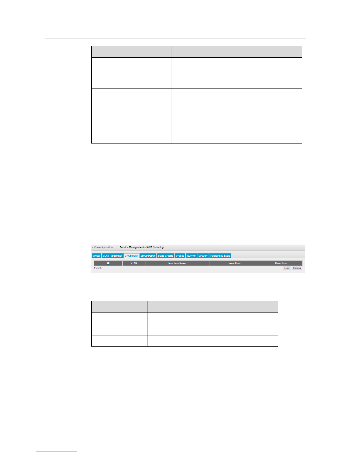
S1700 Managed Series Ethernet Switches
Web User Manual
5 Service Management
Issue 05 (2012-10-25)
Huawei Proprietary and Confidential
Copyright © Huawei Technologies Co., Ltd.
73
Item
Description
Last Member Query Interval
Represents the time interval when IGMP receiving the
IGMP leave group message sent by the host, and
sending IGMP specific group query message. The unit
is second.
Robustness Variable
This value is adjusted by the expected packet loss ratio.
This value should be corresponding increased to adapt
to the increasing packet loss if packet loss is high on
LAN. The value range is 2~5; the default is 2.
Query Interval
This value is used to set the time interval for
transmitting IGMP query. The range is 1~31744
second(s); the default is 125 seconds.
Step 3 Adjust the needed IGMP settings.
Step 4 Click Apply button to apply all the changes made.
----End
5.6.3 Group Deny
Click Service Management>IGMP Snooping> Group Deny to view interface‟s IGMP
Snooping learning status; shown as the figure below.
Figure 5-37 Group Deny
Table 5-24 Parameters of Group Deny
Item
Description
VLAN
VLAN ID number.
Interface Name
Interface number in this VLAN.
Group Deny
Learning status of interface
Create IGMP Snooping Group Deny
Step 1 Click Service Management>IGMP Snooping> Group Deny.
Step 2 Click New button to open the configuration page shown as the figure below.
Page 84
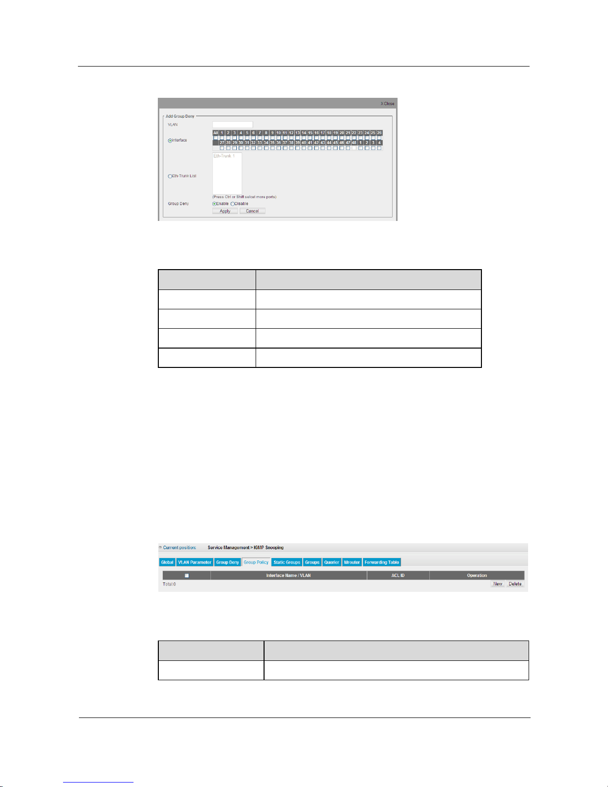
S1700 Managed Series Ethernet Switches
Web User Manual
5 Service Management
Issue 05 (2012-10-25)
Huawei Proprietary and Confidential
Copyright © Huawei Technologies Co., Ltd.
74
Figure 5-38 New Group Deny
Table 5-25 Parameters of Group Deny
Item
Description
VLAN
Specify VLAN for transmitting multicast service.
Interface
Select interface.
Eth-Trunk List
Select Trunk.
Group Deny
Enable or disable interface‟s learning function.
Step 3 Configure the needed parameters.
Step 4 Click Apply button to apply all the changes made.
----End
5.6.4 Group Policy
Click Service Management> IGMP Snooping>Group Policy to check information of multicast
policy on the switch; shown as the figure below.
Figure 5-39 IGMP Group Policy
Table 5-26 Parameters of IGMP Group Policy
Item
Description
Interface Name/ VLAN
Interface name / VLAN ID.
Page 85
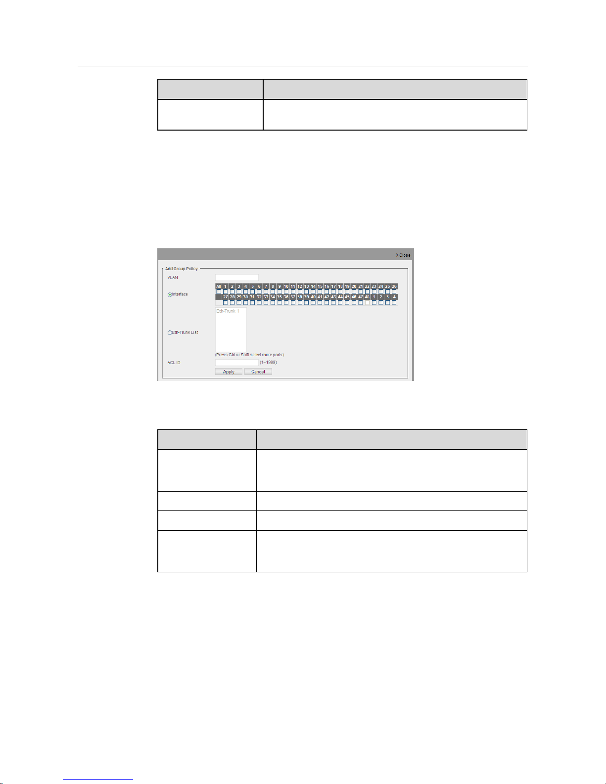
S1700 Managed Series Ethernet Switches
Web User Manual
5 Service Management
Issue 05 (2012-10-25)
Huawei Proprietary and Confidential
Copyright © Huawei Technologies Co., Ltd.
75
Item
Description
ACL ID
Apply the ACL number on the interface. The switch will use this
ACL rule to deal with multicast message when receiving it.
Create an IGMP Group Policy
Step 1 Click Service Management> IGMP Snooping> Group Policy.
Step 2 Click New button to open the configuration page shown as the figure below.
Figure 5-40 Add Group Policy
Table 5-27 Parameters of IGMP Snooping Group Policy
Item
Description
VLAN
Specify VLAN for transmitting multicast service ; if no specified
interface or Eth-Trunk, this configuration is multicast policy based
on VLAN ; otherwise, the multicast policy based on interface.
Interface
Select Interface.
Eth-Trunk List
Select Trunk.
ACL ID
When applying the ACL number on interface, regardless of
configuring VLAN multicast policy or configuring interface's
multicast policy, only one ACL rule can be configured.
Step 3 Configure the needed parameter.
Step 4 Click Apply button to apply all the changes below.
----End
Page 86
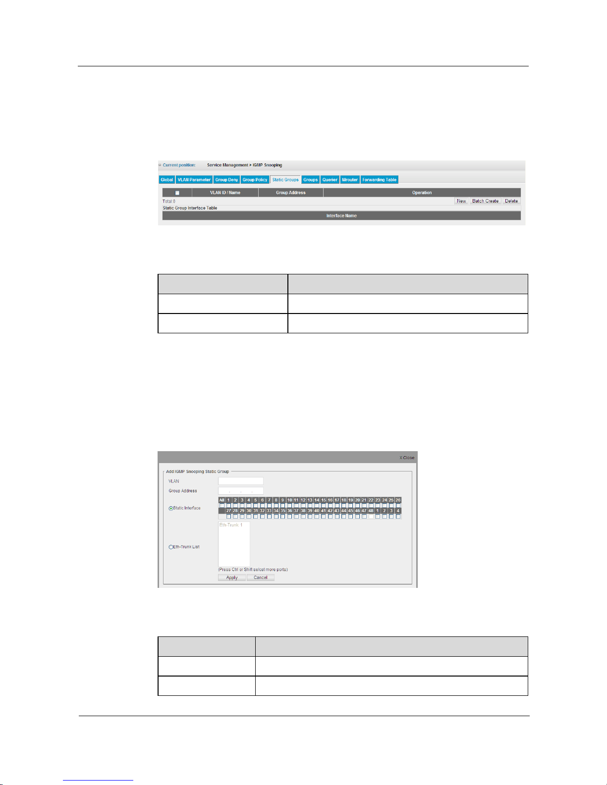
S1700 Managed Series Ethernet Switches
Web User Manual
5 Service Management
Issue 05 (2012-10-25)
Huawei Proprietary and Confidential
Copyright © Huawei Technologies Co., Ltd.
76
5.6.5 Static Groups
Click Service Management>IGMP Snooping> Static Groups to view information of static
groups on switch; the configuration page is shown as the figure below.
Figure 5-41 IGMP Snooping Static Groups
Table 5-28 Parameters of IGMP Snooping Static Groups
Item
Description
VLAN ID /Name
VLAN ID number /VLAN name.
Group Address
IP address for static multicast group.
Add IGMP Snooping Static Group
Step 1 Click Service Management>IGMP Snooping> Static Groups.
Step 2 Click New button, opening the configuration page shown as the figure below.
Figure 5-42 Add IGMP Snooping Static Group
Table 5-29 Parameters of IGMP Snooping Static Groups
Item
Description
VLAN
Specifiy VLAN for transmitting multicast service.
Group Address
The IP address for the newly created static multicast group.
Page 87
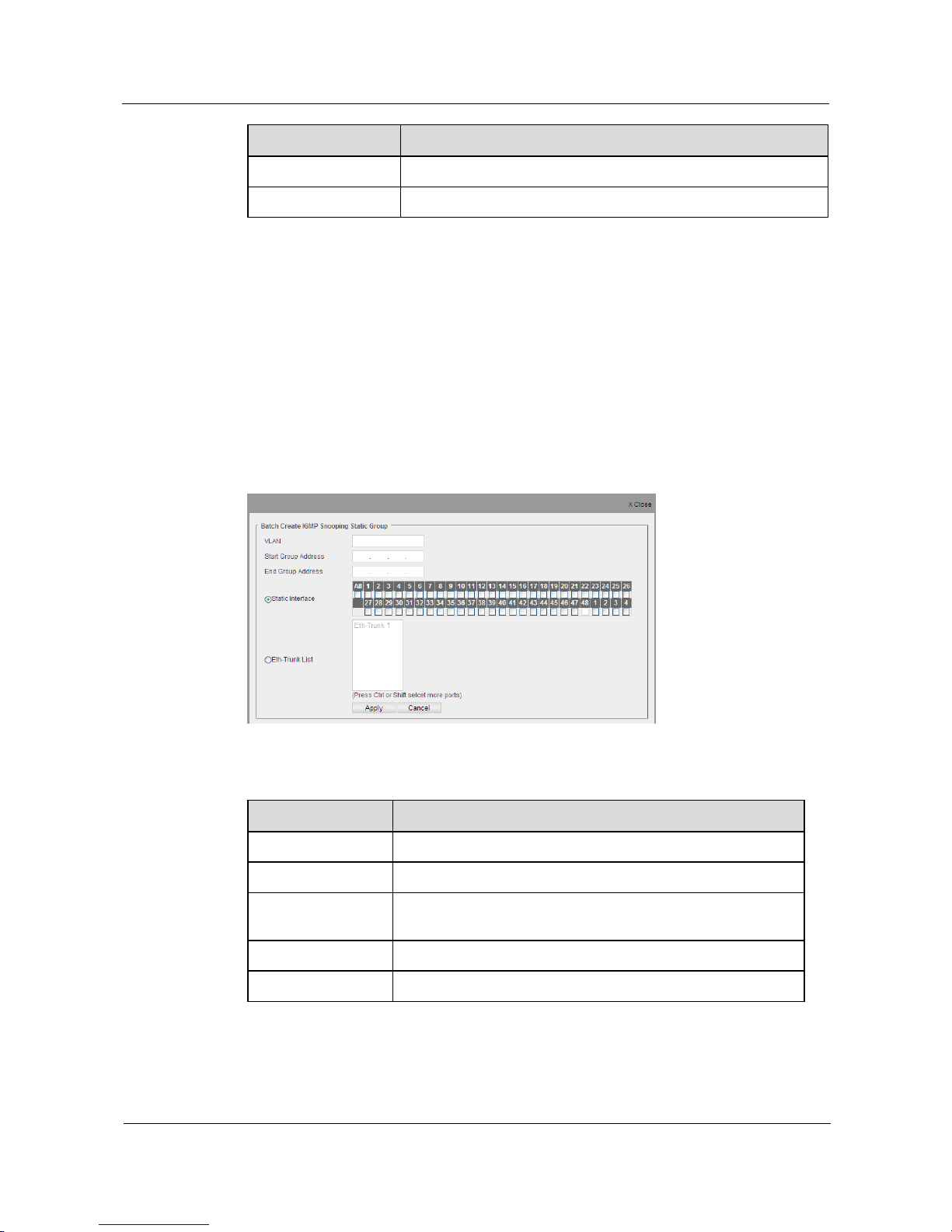
S1700 Managed Series Ethernet Switches
Web User Manual
5 Service Management
Issue 05 (2012-10-25)
Huawei Proprietary and Confidential
Copyright © Huawei Technologies Co., Ltd.
77
Item
Description
Static Interface
Select interface for receiving this static multicast group.
Eth- Trunk List
Select Trunk for receiving this static multicast group data.
Step 3 Configure the needed parameter.
Step 4 Click Apply button to apply all the changes made.
----End
Batch Create Static Groups
Step 1 Click Service Management> IGMP Snooping> Static Groups.
Step 2 Click Batch Create button, opening the configuration page shown as the figure below.
Figure 5-43 Batch Create Static Groups
Table 5-30 Parameters of IGMP Snooping Static Groups
Item
Description
VLAN
Specify VLAN for transmitting multicast service.
Start Group Address
Batch creation of start IP address for new static multicast group.
End Group Address
Batch creation of the end IP address for new static multicast
group.
Static Interface
Select interface for receiving this static multicast group data.
Eth-Trunk List
Select Trunk for receiving this static multicast group data.
Step 3 Configure the needed parameter.
Step 4 Click Apply button to apply all the changes made.
Page 88
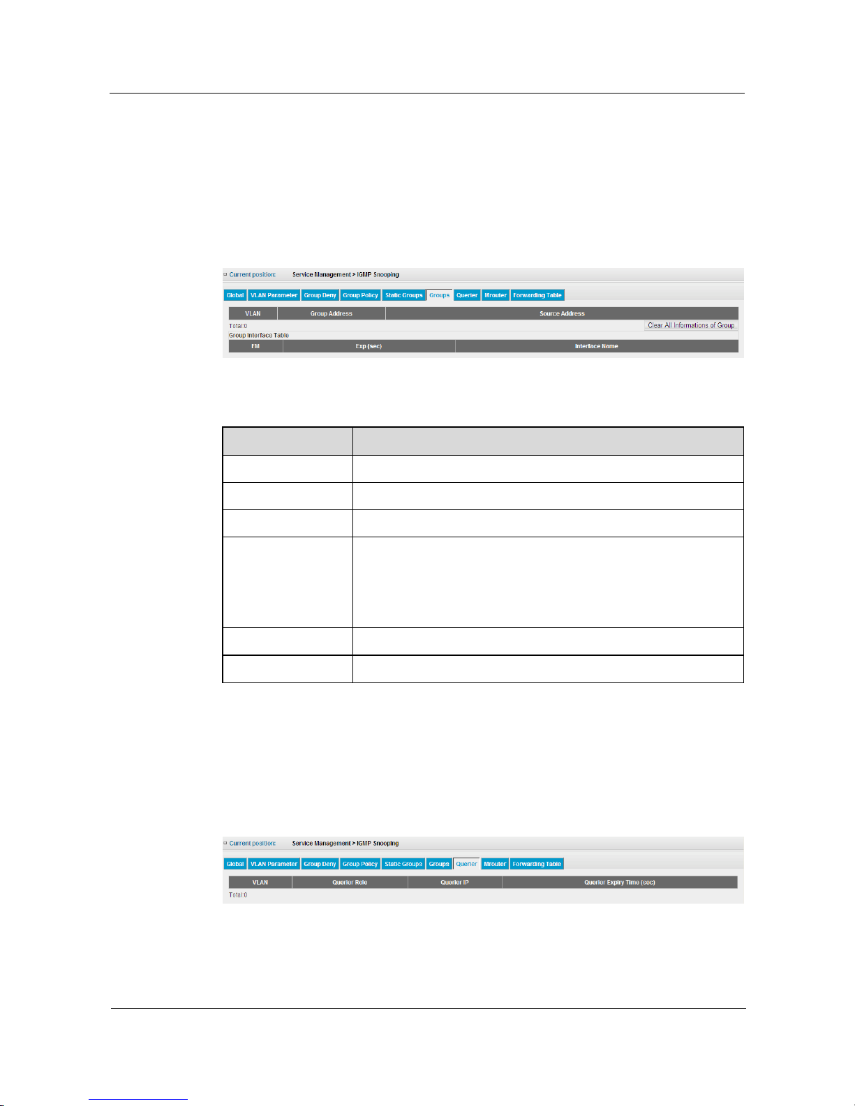
S1700 Managed Series Ethernet Switches
Web User Manual
5 Service Management
Issue 05 (2012-10-25)
Huawei Proprietary and Confidential
Copyright © Huawei Technologies Co., Ltd.
78
----End
5.6.6 Groups
Click>Service Management> IGMP Snooping> Groups to check group information on switch;
the configuration page is shown as the figure below.
Figure 5-44 IGMP Snooping Groups
Table 5-31 Parameters of IGMP Snooping Groups
Item
Description
VLAN
The VLAN for transmitting multicast service.
Group Address
The IP address of multicast group.
Source Address
The source IP address of multicast group.
FM
Multicast group filter mode. Include refers to the multicast data
stream forwarded from the corresponding interface; Exclude means
that, if the source address is *, multicast data stream will be
forwarded from the corresponding interface; if it is not *, multicast
data stream will not be forwarded from the corresponding interface.
Exp (sec)
The aging time of multicast group.
Interface Name
The interface for transmitting multicast service.
5.6.7 Querier
Click Service Management> IGMP Snooping> Querier to check querier information on
switch; the configuration page is shown as the figure below.
Figure 5-45 IGMP Snooping Querier
Page 89
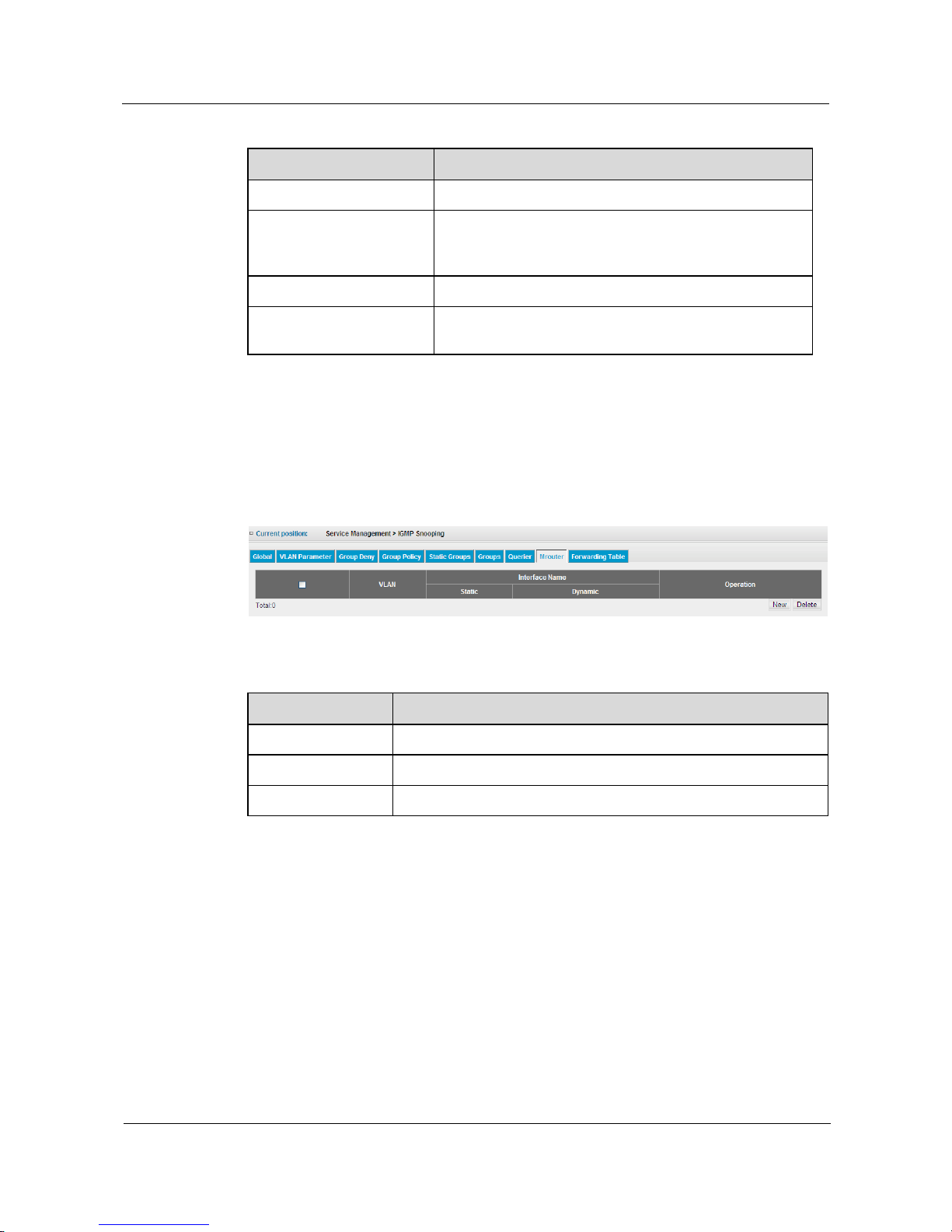
S1700 Managed Series Ethernet Switches
Web User Manual
5 Service Management
Issue 05 (2012-10-25)
Huawei Proprietary and Confidential
Copyright © Huawei Technologies Co., Ltd.
79
Table 5-32 Parameters of IGMP Snooping Querier
Item
Description
VLAN
The VLAN for transmitting multicast service.
Querier Role
Display switch actions that transmits query packet. Querier
indicates switch sends IGMP query packet. Non-Querier
indicates switch does not send IGMP inquiry packet.
Querier IP
IP address of querier.
Querier Expiry Time (sec)
Timeout period of Querier, and ‟-‟indicates that switch
itself works as a querier.
5.6.8 Mrouter
Click Service Management> IGMP Snooping> Mrouter to check information of route
interface on switch; the configuration page is shown as the figure below.
Figure 5-46 IGMP Snooping Mrouter
Table 5-33 Parameters of IGMP Snooping Mrouter
Item
Description
VLAN
The VLAN for transmitting multicast service.
Static
The static configuration of multicast router interface on switch.
Dynamic
The multicast router interface detected by the dynamic on switch.
Add IGMP Snooping Route Interface
Step 1 Click Service Management> IGMP Snooping> Mrouter.
Step 2 Click New button, opening the configuration page shown as the figure below.
Page 90
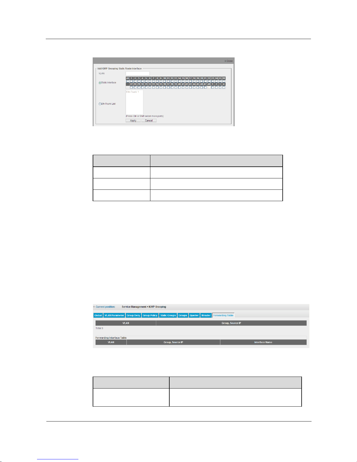
S1700 Managed Series Ethernet Switches
Web User Manual
5 Service Management
Issue 05 (2012-10-25)
Huawei Proprietary and Confidential
Copyright © Huawei Technologies Co., Ltd.
80
Figure 5-47 Create Mrouter
Table 5-34 Parameters of IGMP Snooping Mrouter
Item
Description
VLAN
Specify VLAN for transmitting multicast service.
Static Interface
Specify interface to connect multicast router.
Eth-Trunk List
Specify Trunk to connect multicast router.
Step 3 Configure the needed parameter.
Step 4 Click Apply button to apply all the changes made.
----End
5.6.9 Forwarding Table
Click Service Management> IGMP Snooping>Forwarding Table to check forwarding
information on switch; shown as the figure below.
Figure 5-48 IGMP Snooping Forwarding Table
Table 5-35 Parameters of IGMP Snooping Forwarding Table
Item
Description
VLAN
Specify the VLAN which used to transmite multicast
service.
Page 91

S1700 Managed Series Ethernet Switches
Web User Manual
5 Service Management
Issue 05 (2012-10-25)
Huawei Proprietary and Confidential
Copyright © Huawei Technologies Co., Ltd.
81
Item
Description
Group, Source IP
Multicast server address that sends data stream to
specified multicast.
Interface Name
The downlink interfaces or interface aggregation of the
specified multicast group that receives data stream,
which includes multicast router interface with dynamic
or static configuration.
Page 92
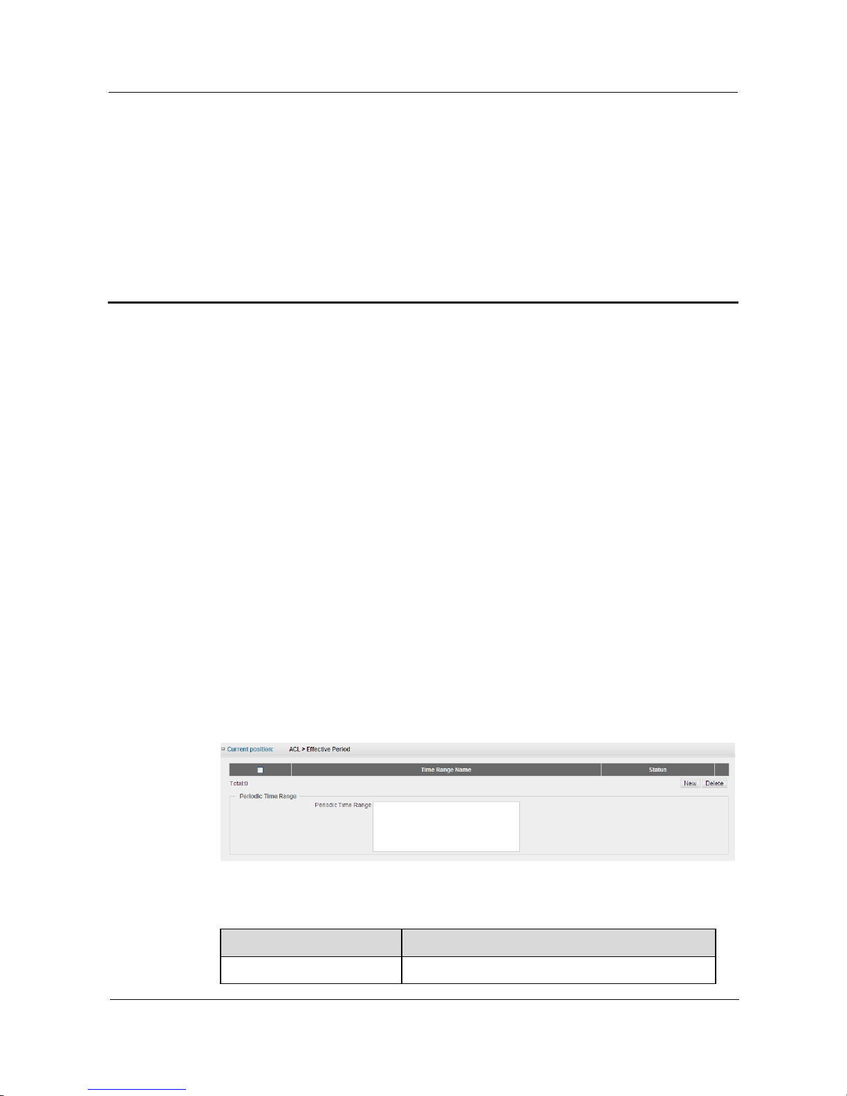
S1700 Managed Series Ethernet Switches
Web User Manual
6 ACL Configuration
Issue 05 (2012-10-25)
Huawei Proprietary and Confidential
Copyright © Huawei Technologies Co., Ltd.
82
6 ACL Configuration
About This Chapter
In ACL configuration page, user can create ACL based on IP, MAC, IPv6 and User-default to
control network traffic and realize network security access.
The whole ACL Control is divided into 3 steps. Step 1, configure the effective period of ACL
rule in the effective period. Step 2, configure matched object of ACL rules in ACL profile.
Step 3, apply the formed ACL rules to specified interface or VLAN.
6.1 Effective Period
6.2 ACL Profile
6.3 ACL Application
6.4 HTTP ACL
6.1 Effective Period
Effective Period configures the effective time of applying ACL rule. Click ACL>Effective
Period, the configuration page is shown as the figure below.
Figure 6-1 Configure Effective Period
Table 6-1 Parameters of Configuring Effective Period
Item
Description
Time Range Name
Period name.
Page 93
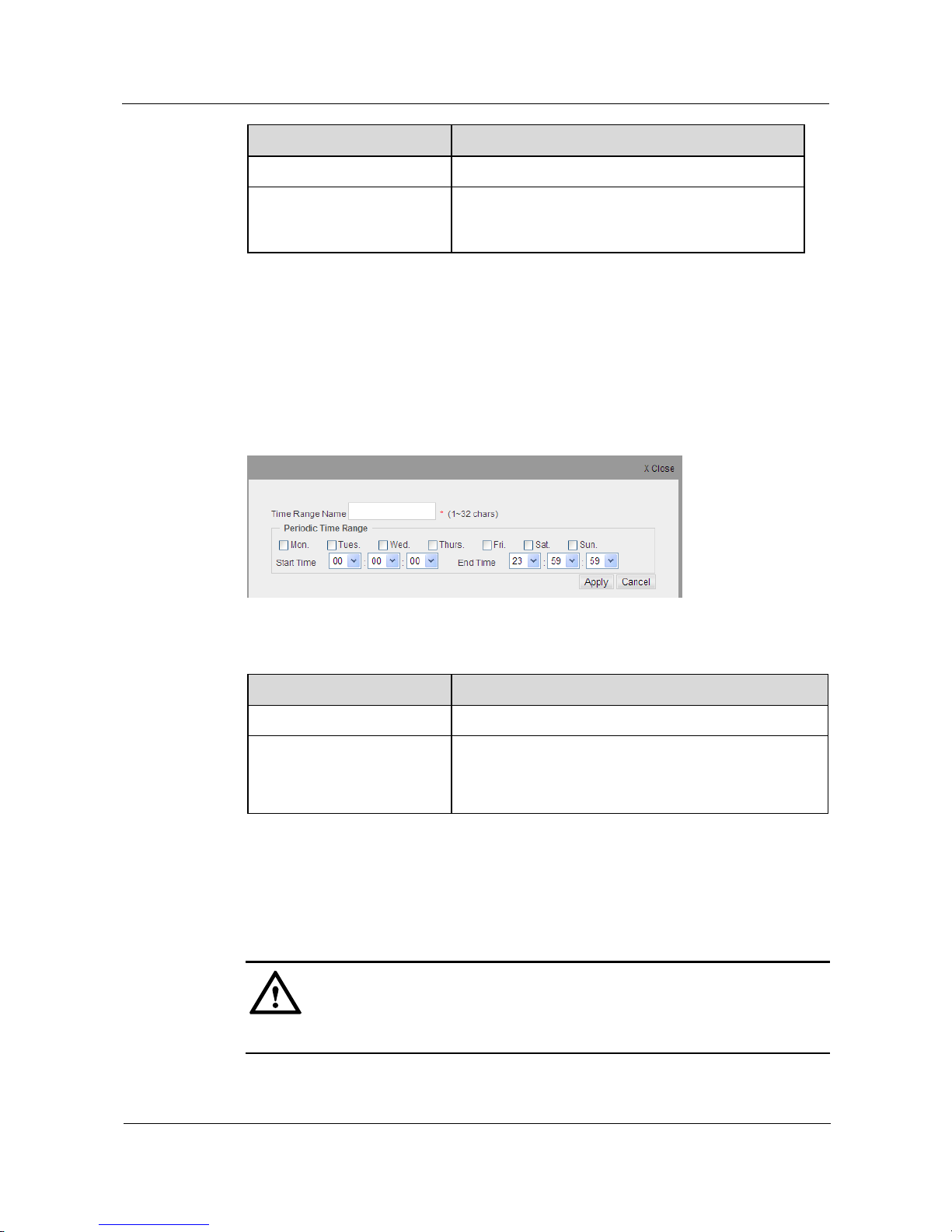
S1700 Managed Series Ethernet Switches
Web User Manual
6 ACL Configuration
Issue 05 (2012-10-25)
Huawei Proprietary and Confidential
Copyright © Huawei Technologies Co., Ltd.
83
Item
Description
Status
Disply whether this period is active.
Periodic Time Range
Click an entry of time range from the lifetime list. The
periodic time range will display the entry lifetime in
details
Create an Effective Period
Step 1 Click ACL>Effective Period.
Step 2 Click New button to add an new effective period to open the configuration page shown as the
figure below.
Figure 6-2 Edit Effective Period
Table 6-2 Parameters of Editing Effective Period
Item
Description
Time Range Name
Enter a name for effective period rule.
Periodic Time Range
Week: Select the day of the week to apply ACL rule.
Start Time: Select the start time to apply ACL rule.
End Time: Select the end time to apply ACL r
Step 3 Configure the needed parameter.
Step 4 Click Apply button to apply all the changes made. The newly created effective period will be
displayed in list of effective period.
CAUTION
If the created effective period has been already existed, it cannot be recreated.
Page 94
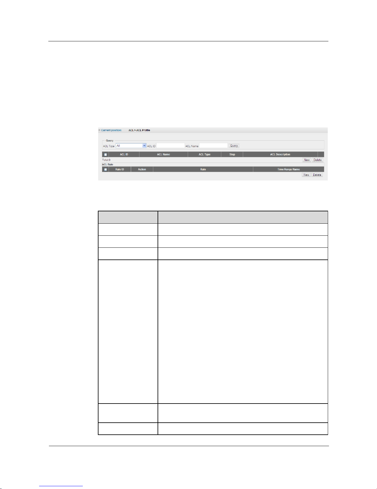
S1700 Managed Series Ethernet Switches
Web User Manual
6 ACL Configuration
Issue 05 (2012-10-25)
Huawei Proprietary and Confidential
Copyright © Huawei Technologies Co., Ltd.
84
6.2 ACL Profile
Creating an ACL rule is divided into two basic steps. First, must create an ACL and then
specify the type, name, number and step of ACL. Second, must create frame-matching criteria
for switch in ACL.
Click ACL>ACL Profile to configure ACL rule for switch; the configuration page is shown as
the figure below.
Figure 6-3 Configure ACL Profile
Table 6-3 Parameters of Configuring ACL Profile
Item
Description
Query
Search ACL entry by "ACL Type', „ACL Number‟ or „ACL Name‟.
ACL ID
Number for ACL entry.
ACL Name
Name for ACL entry.
ACL Type
Display the match types for ACL entry :Standard IP, Extended IP,
Extended Ipv6, Extended MAC or User-defined.
Standard IP: indicate switch to detect source IP address for each
packet‟s header. Only can detect IPv4 (Ether Type is 0x0800).
Extended IP: indicate switch to detect protocol type,
source/destination IP address, source/destination interface member,
IP/TOS priority or TCP mark for each packet header. Only can
detect IPv4 packet (Ether Type is 0x0800).
Extended IPv6: indicate switch detects protocol type,
source/destination IPv6 address, source/destination Interface
IP/TOS priority or TCP tag for each IPv6 packet header. Only can
detect IPv6 packet (Ether Type is 0x86DD).
Extended MAC: Indicates the switch to detect each frame header‟s
source/destination MAC address, Ethernet type or 802.1p priority.
Only can detect IP packets (Ether Type, non-0x0800 IPv4 and none
0x86DD IPv6).
User-defined: user can specify the address and content of test kits,
please refer to user-defined rule creation.
Step
The starting number and distribution interval when the step
automatically assigns rule number.
ACL Description
Display functional description of ACL entry.
Page 95
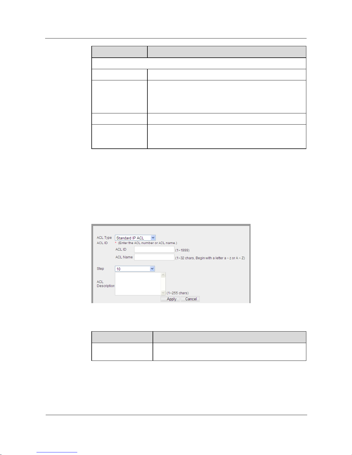
S1700 Managed Series Ethernet Switches
Web User Manual
6 ACL Configuration
Issue 05 (2012-10-25)
Huawei Proprietary and Confidential
Copyright © Huawei Technologies Co., Ltd.
85
Item
Description
ACL Rule
Rule ID
Display rule number.
Action
Permit indicates switch forwarding packets which match with the
rule.
‟Deny‟ indicates switch dropping packets which does not match
with the rule.
Rule
Display the field viewed by the rule.
Time Range Name
Display effective time of the ACL rule, if no effective time is
specified, and then it takes effect with a rule and applies it to
interface or VLAN time range.
Create an ACL Entry
Step 1 Click ACL>ACL Profile.
Step 2 Click New button to add a new ACL entry, opening the configuration page shown as the
figure below.
Figure 6-4 Edit ACL Profile
Table 6-4 Parameters of Editing ACL Profile
Item
Description
ACL Type
Select the matching types for ACL entry: Standard IP, Extended
IP, Extended IPv6, Extended MAC or User-defined.
Page 96
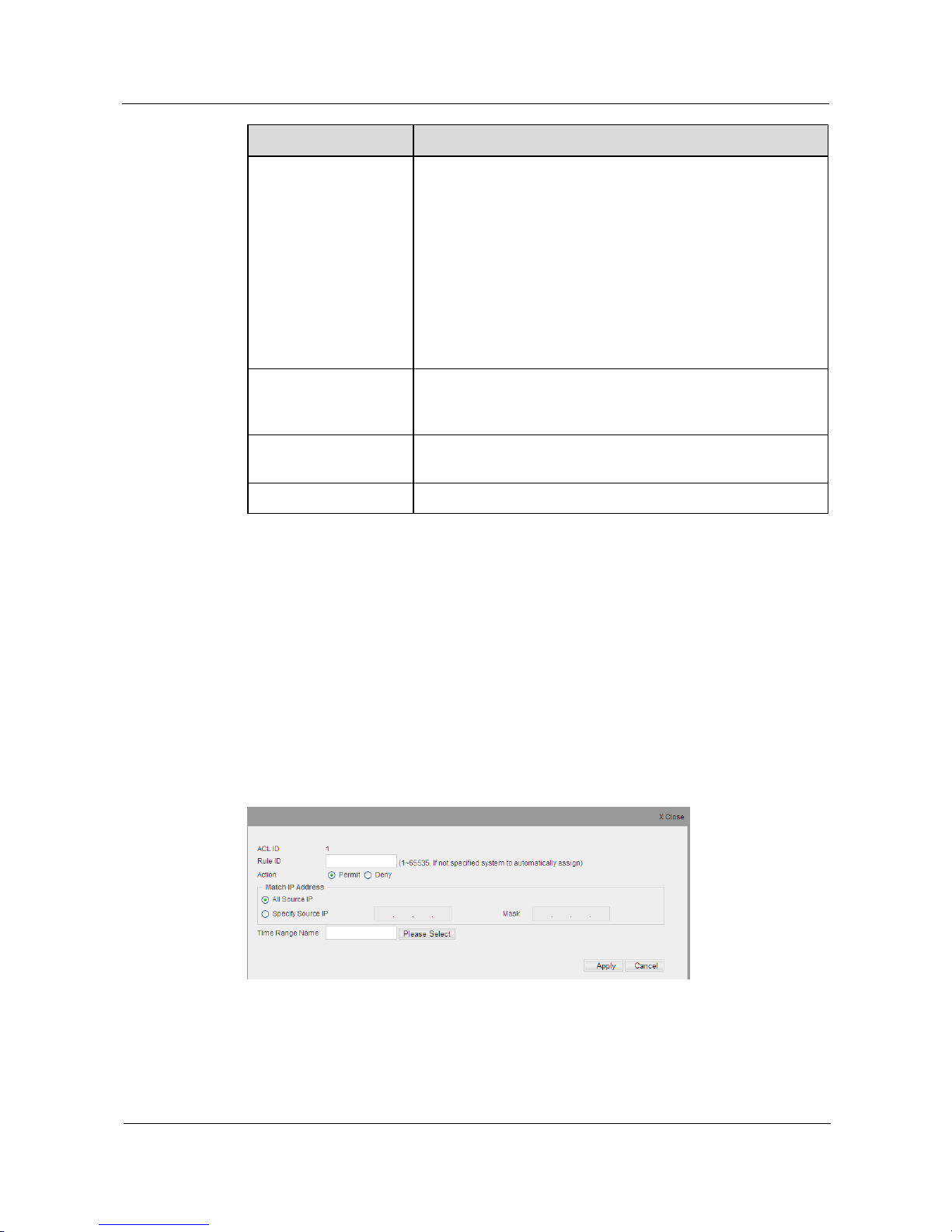
S1700 Managed Series Ethernet Switches
Web User Manual
6 ACL Configuration
Issue 05 (2012-10-25)
Huawei Proprietary and Confidential
Copyright © Huawei Technologies Co., Ltd.
86
Item
Description
ACL ID
ACL ID: enter ACL entry ID.
1.Standard IP :1-1999
2.Extended IP: 2000-3999
3.Extended IPv6 :4000-5999
4.Extended MAC: 6000-7999
5.User-defined :10000 -10,999
ACL Name: enter ACL entry name.
(At least enter ACL number or ACL name, if only enter one of
them, another one will be automatically created by the system)
Offset Chunk (1-4)
Create segments (Chunk) needed for user-defined ACL and
specify offset (Offset in bytes) See chapter Create a New
User-Defined Rules.
Step
The starting number and distribution interval of automatically
assigning rule number.
ACL Description
Enter the description of ACL entry function.
Step 3 Configure the needed parameter.
Step 4 Click Apply button to apply all the changes made.
----End
Create a Standard IP Rule
Step 1 Click ACL>ACL Profile.
Step 2 Click a created standard IP rule in ACL list, and click New in the list box of ACL Rule to add
a new rule, opening the configuration page shown as the figure below.
Figure 6-5 Create Standard IP Rule
Page 97
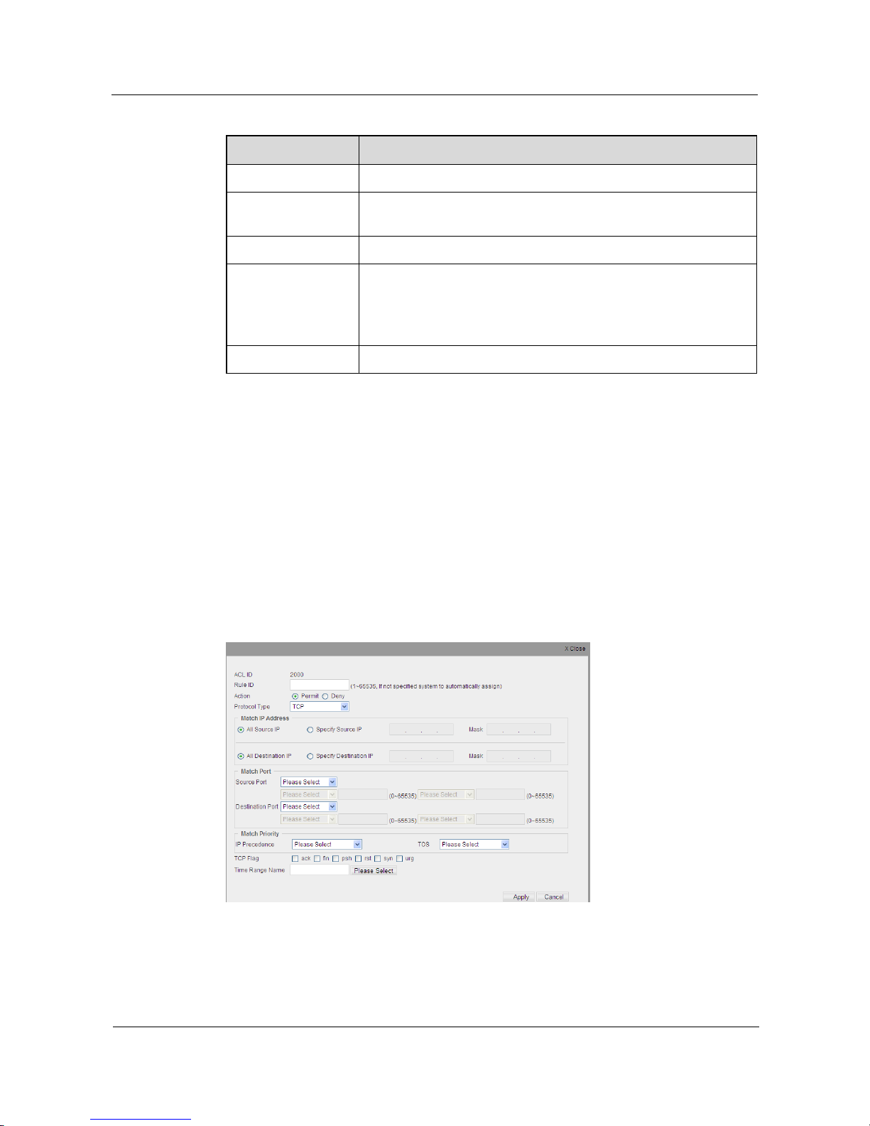
S1700 Managed Series Ethernet Switches
Web User Manual
6 ACL Configuration
Issue 05 (2012-10-25)
Huawei Proprietary and Confidential
Copyright © Huawei Technologies Co., Ltd.
87
Table 6-5 Parameters of Standard IP Rule
Item
Description
ACL ID
ACL entry ID that the rules belongs to.
Rule ID
Enter an ID for rule and the range is 1~65535. If not specified, the
system, according to rule step, will distribute automatically.
Action
Specify switch to permit or deny data stream that matches to the rule.
Match IP Address
All Source IP: specify this rule to be applied to all IP data packages.
Specify Source IP /Mask: specify this rule to be applied to the IP data
package of specified IP /mask. The IP address will match the whole
field if no mask entered.
Time Range Name
Click Please Select button to specify effective time for the rule.
Step 3 Configure the needed parameter.
Step 4 Click Apply button to apply all the changes made.
----End
Create an Extending IP Rule
Step 1 Click ACL>ACL Profile.
Step 2 Click a created extending IP rule in the ACL list box, and click New button in list box of ACL
Rule to add a new rule, opening the configuration page shown as the figure below.
Figure 6-6 Create Extended IP Rule
Page 98

S1700 Managed Series Ethernet Switches
Web User Manual
6 ACL Configuration
Issue 05 (2012-10-25)
Huawei Proprietary and Confidential
Copyright © Huawei Technologies Co., Ltd.
88
Table 6-6 Parameters of Extending IP Rules
Item
Description
ACL ID
ACL ID that entry rules belongs to.
Rule ID
Enter an ID for rule and the range is 1~65535. If not specified, the
system will distribute automatically.
Action
Specify switch to permit or deny data stream that matches to the rule.
Protocol Type
Specify IP protocol type that needs to be matched data.
Match IP Address
Source IP address: All Source IP - specify this rule to be applied to all
IP data packages; Specify Source IP/Mask - specify this rule to be
applied to the IP data package of specified IP address/mask. The IP
address will match the whole field if no mask entered.
Destination IP address: All Destination IP – specify this rule to be
applied to all IP data packages; Specify Destination IP/Mask - specify
this rule to be applied to the IP data package of specified IP
address/mask. The IP address will match the whole field if no mask
entered.
Match Port
Specify the TCP / UDP source port and destination port for data to be
matched.
Match Priority
Specify the IP priority and TOS fields for data to be matched.
TCP Flag
Specify the TCP flag field for data to be matched.
Match ICMP
Specify the matched data fields, including the ICMP type and ICMP
Message Code.
Fragments
Use checkbox to specify whether to match packet fragmentation for
this kind of protocol.
Time Range Name
Click the Select button to specify the effective period of the rules.
Step 3 Configure the needed parameter.
Step 4 Click Apply button to apply all the changes made.
----End
Create a Rule for Extending IPv6
Step 1 Click ACL>ACL Profile.
Step 2 Click a created extending IPv6 rule in ACL list, and click New button in the list box of ACL
Rule, opening the configuration page shown as the figure below.
Page 99
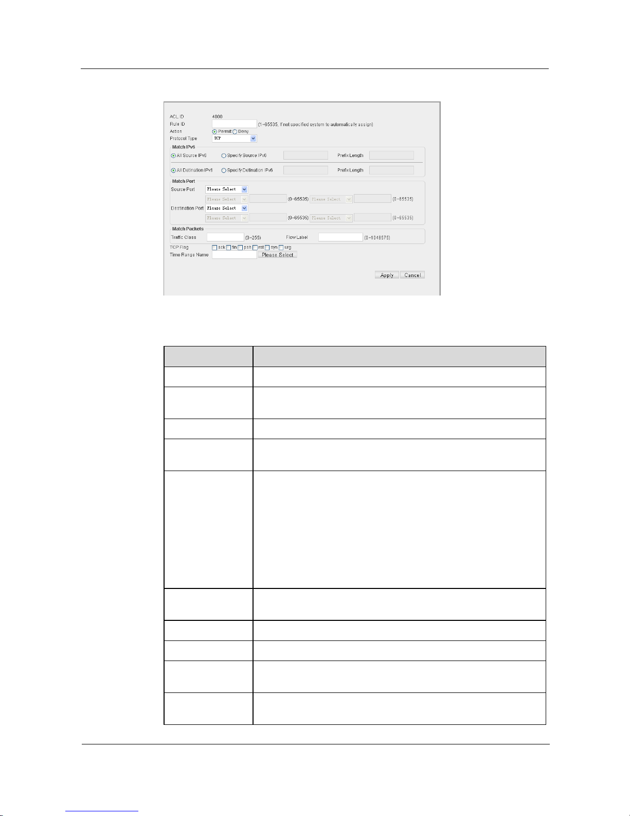
S1700 Managed Series Ethernet Switches
Web User Manual
6 ACL Configuration
Issue 05 (2012-10-25)
Huawei Proprietary and Confidential
Copyright © Huawei Technologies Co., Ltd.
89
Figure 6-7 Create Rule of Extending IPv6
Table 6-7 Parameters of Extending IPv6 Rule
Item
Description
ACL ID
ACL entry number that rule belongs to.
Rule ID
Enter rule number, and the value ranges from 1 to 65535. If not
specified, the system will assign automatically.
Action
Specify switch to permit or deny data stream that matches to the rule.
Protocol Type
Specify IP v6 protocol type to be matched with data (Next Header
Field).
Match IPv6
Source IPv6 address: All source IPv6 - specify this rule to be applied
to all IP data packages; Specify Source IP/Prefix Length - specify this
rule to be applied to the IP data package of specified IP address//prefix
length. The IP address will match the whole field if no mask entered.
Destination IPv6 address: All Destination IPv6 – specify this rule to
be applied to all IP data packages; Specify Destination IP/Prefix
Length - specify this rule to be applied to the IP data package of
specified IP address//prefix length. The IP address will match the
whole field if no mask entered.
Match Port
Specify the TCP / UDP source port and destination port for data to be
matched.
Match Message
Specify service level and Flow Label for data to be matched.
TCP Flag
Specify the TCP flag field for data to be matched.
Match ICMP
Specify the ICMP field including ICMP type and Message Code for
data to be matched.
Fragments
Use checkbox to specify whether to match packet fragmentation for
this kind of protocol.
Page 100
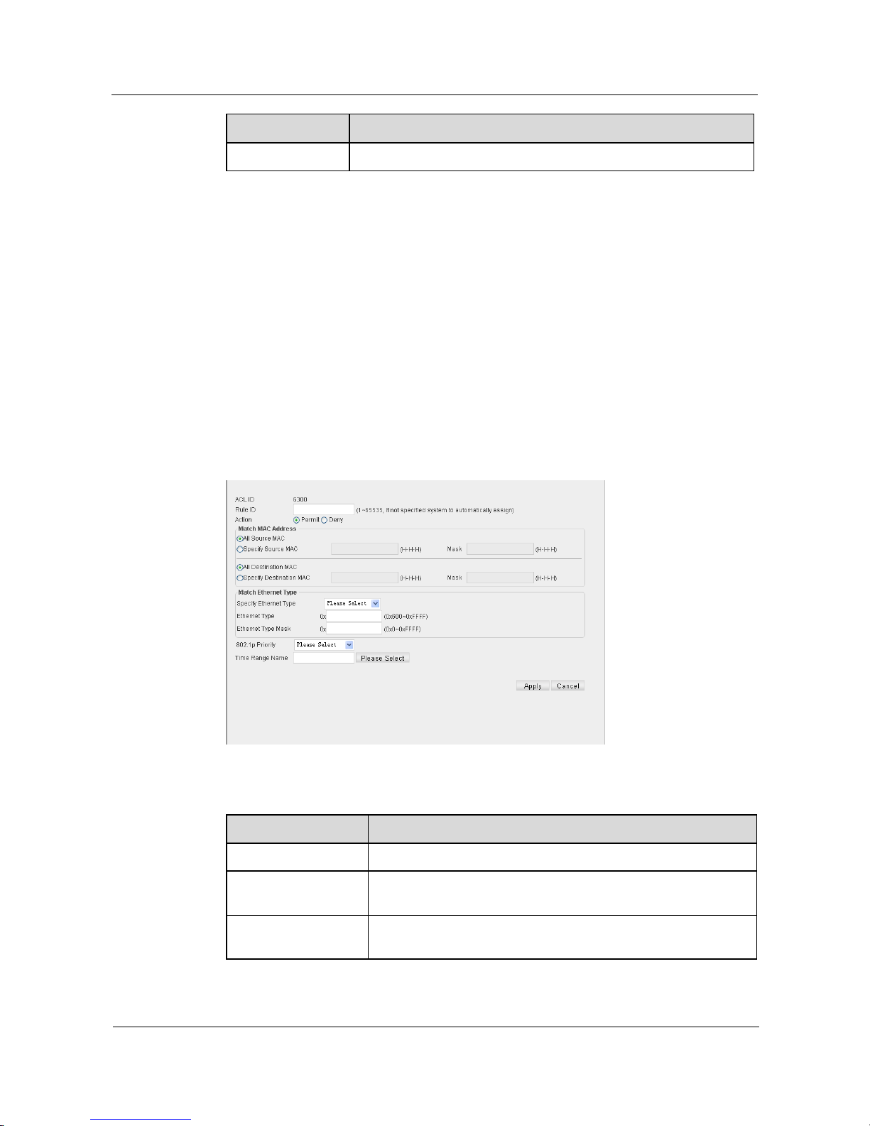
S1700 Managed Series Ethernet Switches
Web User Manual
6 ACL Configuration
Issue 05 (2012-10-25)
Huawei Proprietary and Confidential
Copyright © Huawei Technologies Co., Ltd.
90
Item
Description
Time Range Name
Click the Select button to specify the effective period of the rules.
Step 3 Configure the needed parameter.
Step 4 Click Apply button to apply all the changes made.
----End
Create a Rule for Extension MAC
Step 1 Click ACL>ACL Profile.
Step 2 Click a created extending MAC rule in ACL list, and click New button in the list box of ACL
Rule to add a new rule, opening the configuration shown page as below.
Figure 6-8 New Extension of MAC Rules
Table 6-8 Parameters of Extending MAC Rule
Item
Description
ACL ID
ACL entry number that rule belongs to.
Rule ID
Enter rule number, and the value ranges from 1 to 65535. If not
specified, the system will assign automatically.
Action
Specify switch to permit or deny data stream that matches to the
rule.
 Loading...