

Huawei RTN 905 V100 Quick Installation Manual

HUAWEI TECHNOLOGIES CO., LTD.
RTN 905 V100
IDU Quick Installation Guide (Indoor)
Issue: 01
Date: 2018-10-30

Huawei Technologies Co., Ltd.
Address: Huawei Industrial Base
Bantian, Longgang
Shenzhen 518129
People's Republic of China
Website: http://www.huawei.com
Email: support@huawei.com
No part of this document may be reproduced or transmitted in any form or by any means without prior
written consent of Huawei Technologies Co., Ltd.
Copyright © Huawei Technologies Co., Ltd. 2018. All rights reserved.
Trademarks and Permissions
and other Huawei trademarks are trademarks of Huawei Technologies Co., Ltd.
All other trademarks and trade names mentioned in this document are the property of their respective
holders.
Notice
The purchased products, services and features are stipulated by the contract made between Huawei and
the customer. All or part of the products, services and features described in this document may not be
within the purchase scope or the usage scope. Unless otherwise specified in the contract, all statements,
information, and recommendations in this document are provided "AS IS" without warranties, guarantees
or representations of any kind, either express or implied.
The information in this document is subject to change without notice. Every effort has been made in the
preparation of this document to ensure accuracy of the contents, but all statements, information, and
recommendations in this document do not constitute a warranty of any kind, express or implied.
Before You Start
0
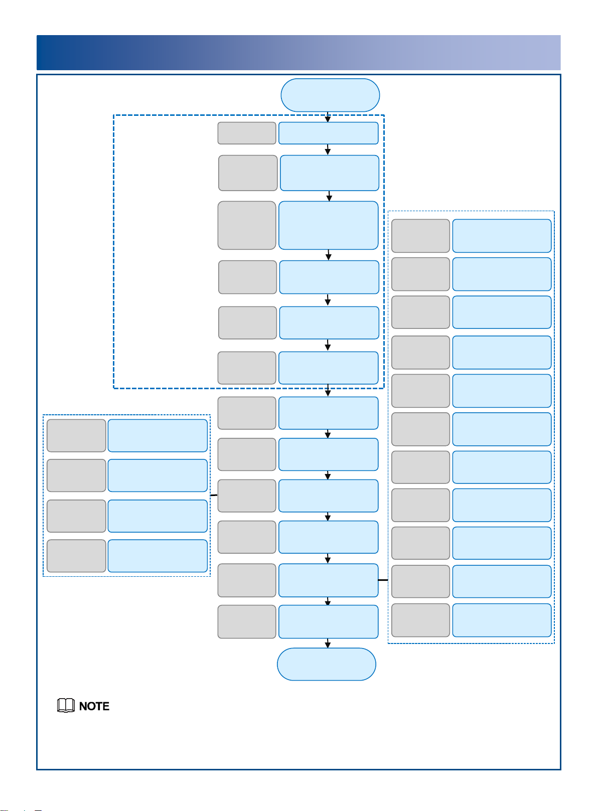
Installation Process
PrecautionsPage 2
Start
Precautions for
Handling RTN 905
1A/1C/1E IF Jumpers
and IF Cables
Page 4
Precautions for Handling
the RTN 905 2A/2E
Toggle Lever Switch
Page 5
Precautions for
Handling RTN 905
2A/2E/2F IF Jumpers
Page 6
Introduction to the
IDU 905 Equipment
Page 8-10
Installing the IDU 905
Pages
11 to 16
Optional: Installing the
E1 Panel
Pages
16 to 17
Installing IDU Cables
Pages
18 to 29
Checking the
Installation
Page 35
End
Installing Power
Cables
Pages
18 to 19
Installing Fibers
Pages
20 to 21
Installing E1 CablesPage 19
Installing IF Cables
Page
22
Installing Ethernet
Service Cables
Page 21
Installing NMS CablesPage 25
Installing Cascade
Cables
Page 23 to
24
Preparing and
Installing External
Alarm Cables
Page 26
Preparing and
Installing External
Clock Cables
Page 28
Preparing and
Installing Synchronous
Data Cables
Page 27
Cable LayoutPage 29
Installing the Chassis
in a 19-Inch Cabinet
Pages
11 to 12
Installing the Chassis
in an ETSI Cabinet
Pages
12 to 13
Wall Mounting
the Chassis
Pages
14 to 15
Desk Mounting
the Chassis
Page 16
Installation ToolsPage 7
Precautions for
Handling RTN 905
2A/2E/2F IF Cables
Page 6
Precautions for
Handling
Power Cables
Page 3
From V100R11C00, the RTN 905 1C is not supported.
1
1
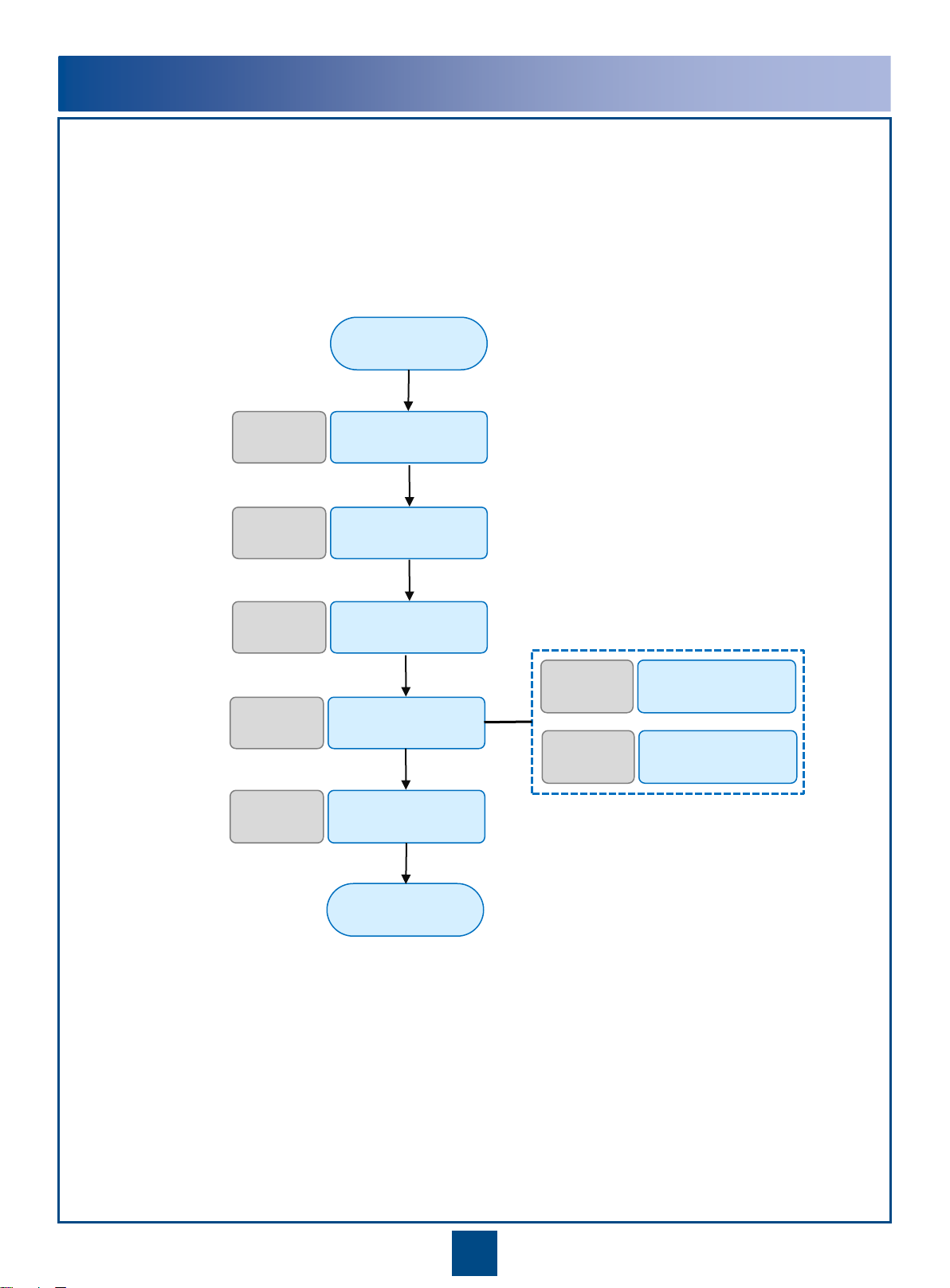
Commissioning Process
Powering On the
Equipment
Page 30
Start
Configuring NE Data
(Using the Web LCT)
Page 31
Aligning Antennas
Pages
32 to 34
Checking the Status of
Radio Links
Page 34
Aligning Single-
Polarized Antennas
Pages
32 to 33
Aligning Dual-
Polarized Antennas
Pages 33
to 34
End
Configuring NE Data
(Using the Hand-Held
Tool)
Page 31
2
Precautions
This document provides guidelines for quick hardware installation.
This document does not describe assembly of equipment prior to delivery; it only describes procedures
for onsite installation.
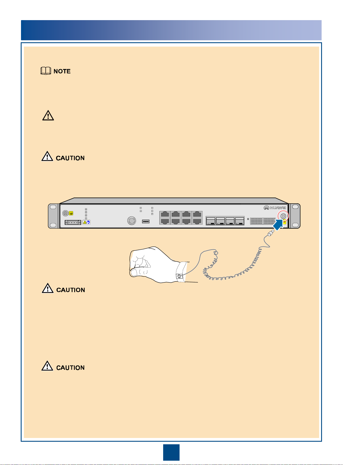
Electrostatic Discharge
To prevent damage to sensitive components caused by electrostatic discharge, wear ESD gloves or an
ESD wrist strap when handling the equipment, boards, or IC chips. Ensure that the ESD wrist strap is
properly grounded.
Binding Cables
Bind fibers or cables inside a cabinet at intervals of not more than 250 mm and user cables at intervals of
not more than 200 mm.
Bind fibers, cables, or corrugated pipes outside a cabinet at intervals equal to the distance between two
horizontal beams. If the cable trough does not have any beams, the intervals should not exceed 250 mm.
Pre-installation Check
Before beginning the installation, check the equipment room, cabinet, power supply, ground cables,
fibers, and associated facilities to confirm that all preparations are complete.
ESD
OptiX RTN 905
Power Supply
The equipment uses a -48 V/-60 V DC power supply. An AC power supply or a high-voltage power
supply may cause equipment damage or even human injuries and therefore is forbidden.
CAUTION
3
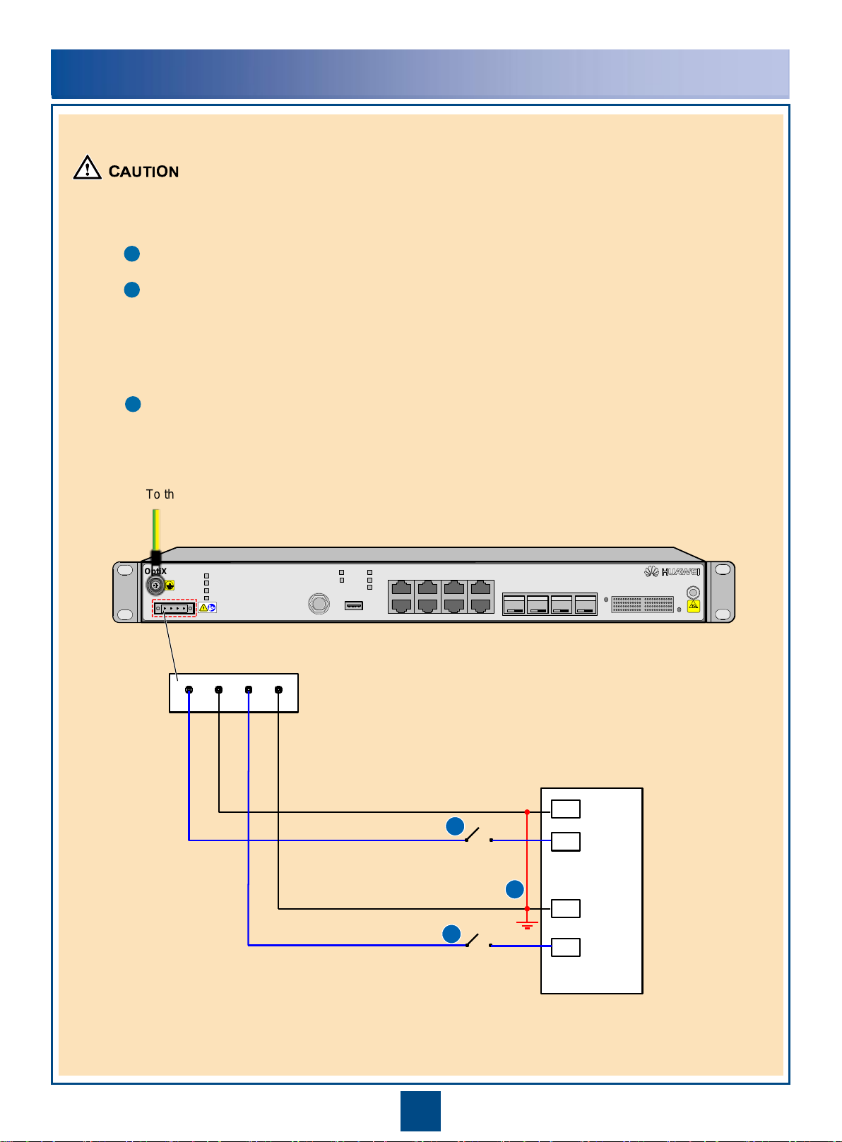
Prior to installing power cables on the RTN 905, confirm that the following conditions are met.
The ground point on the column of the cabinet or the indoor ground bar is properly grounded.
The power cables are connected correctly to the positive and negative terminals of the power supply device.
If a power cable is connected to the positive terminal of the RTN 905 and the negative terminal of the
power supply device, there will be a short circuit that damages the power cable and devices. To prevent
short circuits, install a circuit breaker on each negative terminal of the power supply device. The
recommended fuse capacity is 10 A (1A/2A/1C/1E/2F) or 16 A (2E).
The positive terminals of the power supply device connected to the RTN 905 are grounded. If terminals are
not properly grounded, the devices may be damaged.
PSU
PGND
Precautions for Handling Power Cables
ESD
OptiX RTN 905
RTNB
(+)
NEGB
(-)
RTNA
(+)
NEGA
(-)
A1(+)
A2(-)
B1(+)
B2(-)
1
1
2
.
.
.
.
.
.
SW
SW
DC power port
1
2
3
To the ground point on the column of the cabinet or the indoor ground bar

4
Precautions for Handling RTN 905 1A/1C/1E IF Jumpers and IF Cables
Power off the RTN 905 1A/1C/1E before you remove or connect an IF jumper on the IDU.
Do not remove or connect any IF jumper while the RTN 905 1A/1C/1E is powered on.
Power off the RTN 905 1A/1C/1E before you remove or connect an IF cable on the ODU.
Do not remove or connect any IF cable while the RTN 905 1A/1C/1E is powered on.
OptiX RTN 905
STAT
SRV
PWRA
(+)(-) (-)
NEGA RTNA NEGB RTNB
(+)
-48V
-60V
TURN OFF POWER BEFORE
WARNING
-48V OUTPUT
DISCONNECTING IF CABLE
!
ODU
LINK1 L/A5
L/A6
USB
NMS/COM CLK/TOD/MON
GE2
GE1 GE3
EXT/S1 ALMI/ALMO GE4
ODU-2
ON
PULL
ODU-1
ON
PULL
NMS/COM
EXT/S1
CLK/TOD/MON
ALMI/ALMO
GE1
GE2
GE3
OUT
GE5 GE6 TDMA TDMB
OptiX RTN 905
2 A
STAT
SRV
PWRA
PWRB
LINK1
ACT1
LINK2
ACT2
L/A5
L/A6
USB
ESD
RTNB
(+)
NEGB
(-)
RTNA
(+)
NEGA
(-)
-48V -60V
OFF
OFF
IN
OUT
IN
GE4
1
16
5
Position and Description of the Toggle Lever Switch
Turning on the switch
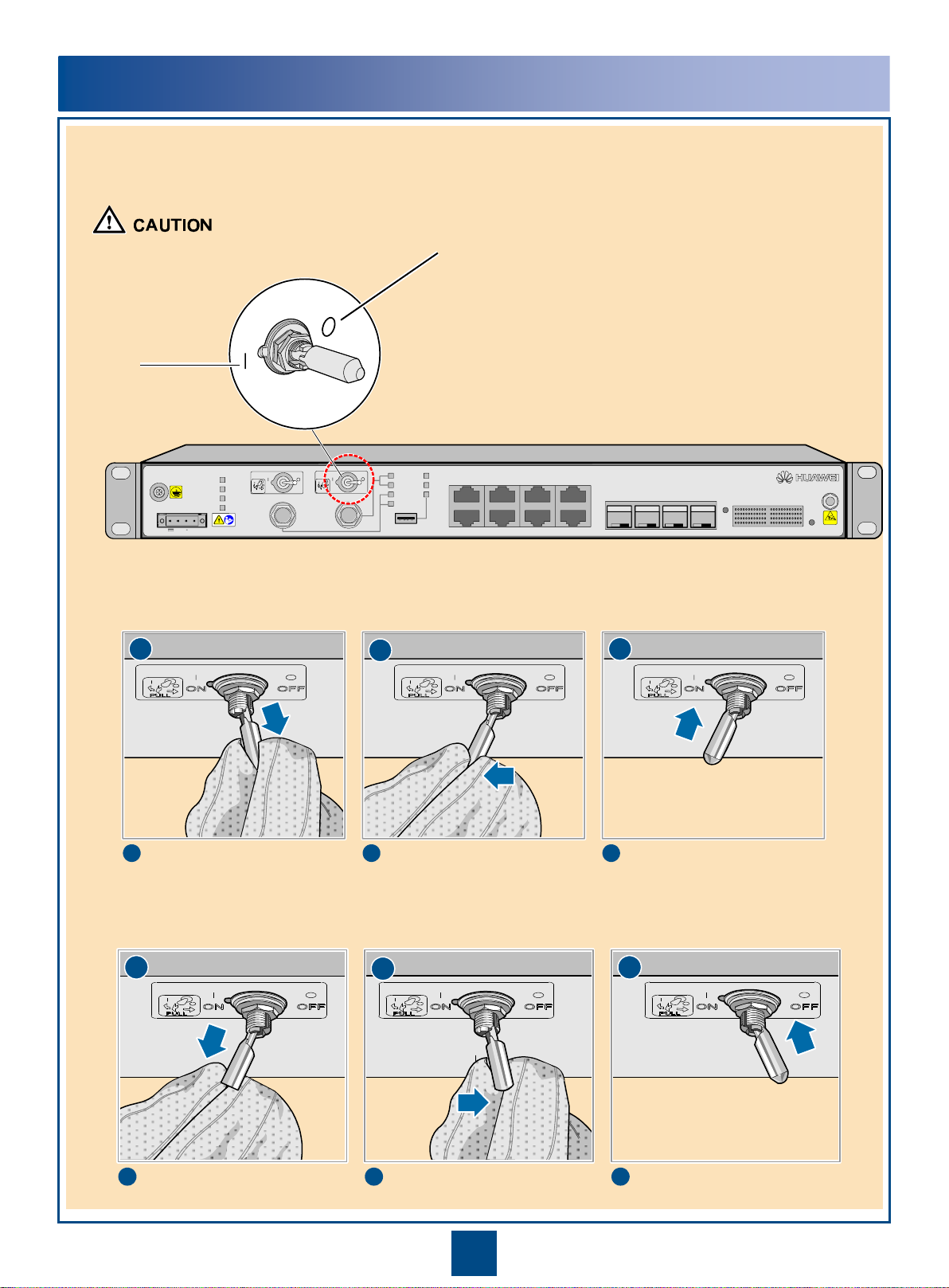
Precautions for Handling the RTN 905 2A/2E Toggle Lever Switch
You must first pull out the toggle lever switch
before turning it.
I: ON
O: OFF
Turning off the switch
1
1
2
2
3
3
Pull the switch out gently.
Turn the switch. Release the switch.
1
1
2
2
3
3
Pull the switch out gently.
Turn the switch. Release the switch.
6
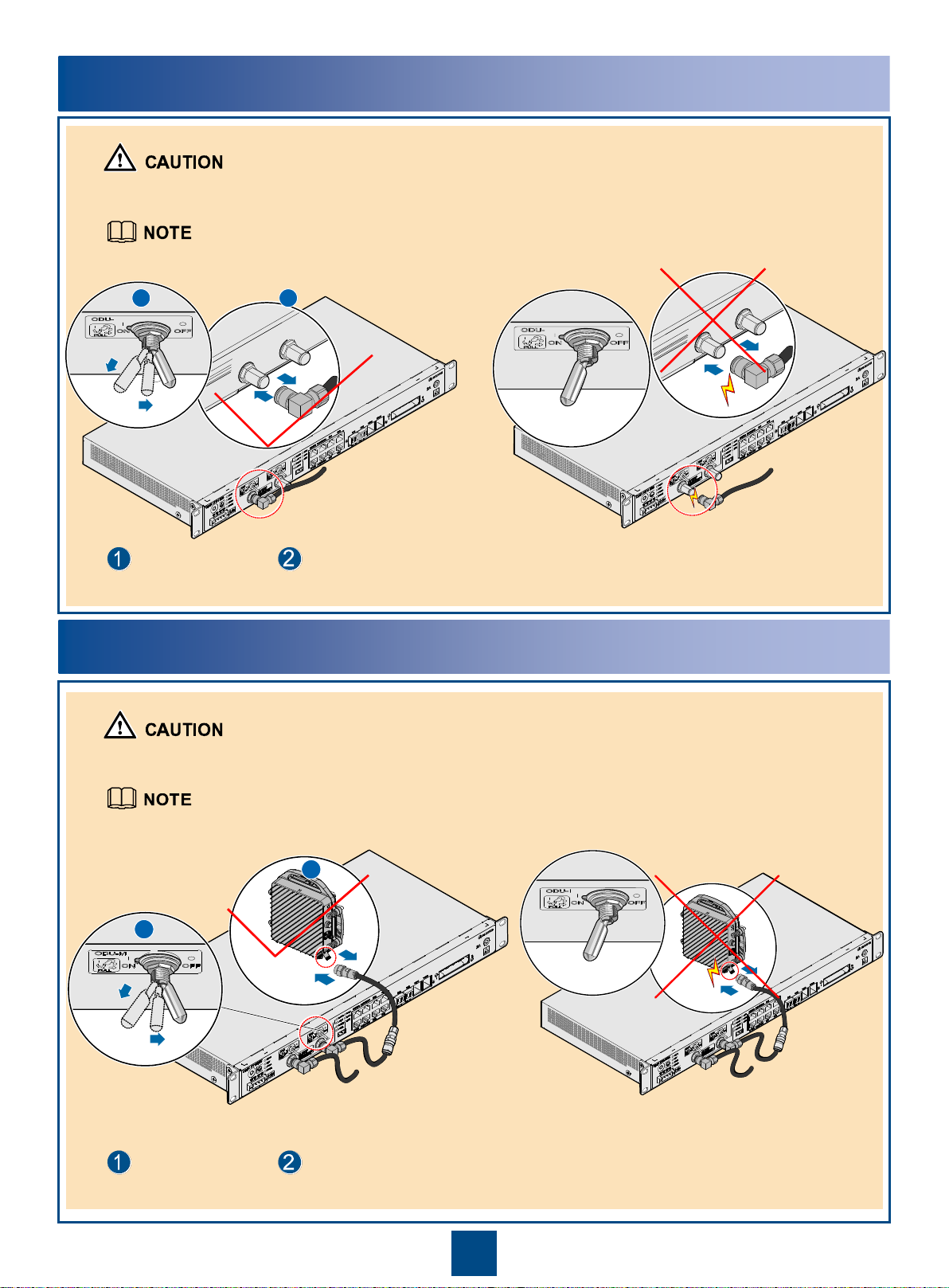
Power off the ODU.
Install or remove an IF fiber connected to the ODU.
Precautions for Handling RTN 905 2A/2E/2F IF Jumpers
Power off the ODU before you remove or install an
IF jumper connected to the ODU.
Do not remove or install an IF jumper connected to
the ODU while the ODU is powered on.
Power off the ODU before you remove or
install an IF cable connected to the ODU.
Do not remove or install an IF cable connected to
the ODU while the ODU is powered on.
Power off the ODU.
Install or remove an IF cable connected to the ODU.
Precautions for Handling RTN 905 2A/2E/2F IF Cables
2
1
1
1 2
2
2
To cut off the power supply to the ODU of the RTN 905 2F, perform related operations on the NMS.
To cut off the power supply to the ODU of the RTN 905 2F, perform related operations on the NMS.

Installation Tools
7
Measuring tape Phillips screwdriver Flat-head screwdriver
Adjustable wrench
Level
Socket wrench Torque w rench Hex key
Wire clippersDiagonal pliersNeedle-nose pliersCombination pliers
Bayonet w rench
Utility knife
Claw hammer
Marker
Ladder
CompassLifting slingPulleyESD gloves
Multimeter PVC tapeFile
Waterproof
insulation tape
NMS/COM
EXT/S1
CLK/TOD/MON
ALMI/ALMO
GE1
GE2
GE3
GE4
GE5 GE6 TDMA TDMB
OptiX RTN 905
1 A
STAT
SRV
PWRA
PWRB
LINK L/A5
L/A6
USB
ESD
RTNB
(+)
NEGB
(-)
RTNA
(+)
NEGA
(-)
-48V -60V
OUT IN OUT IN
USB
E1(1~16)
8
Ports
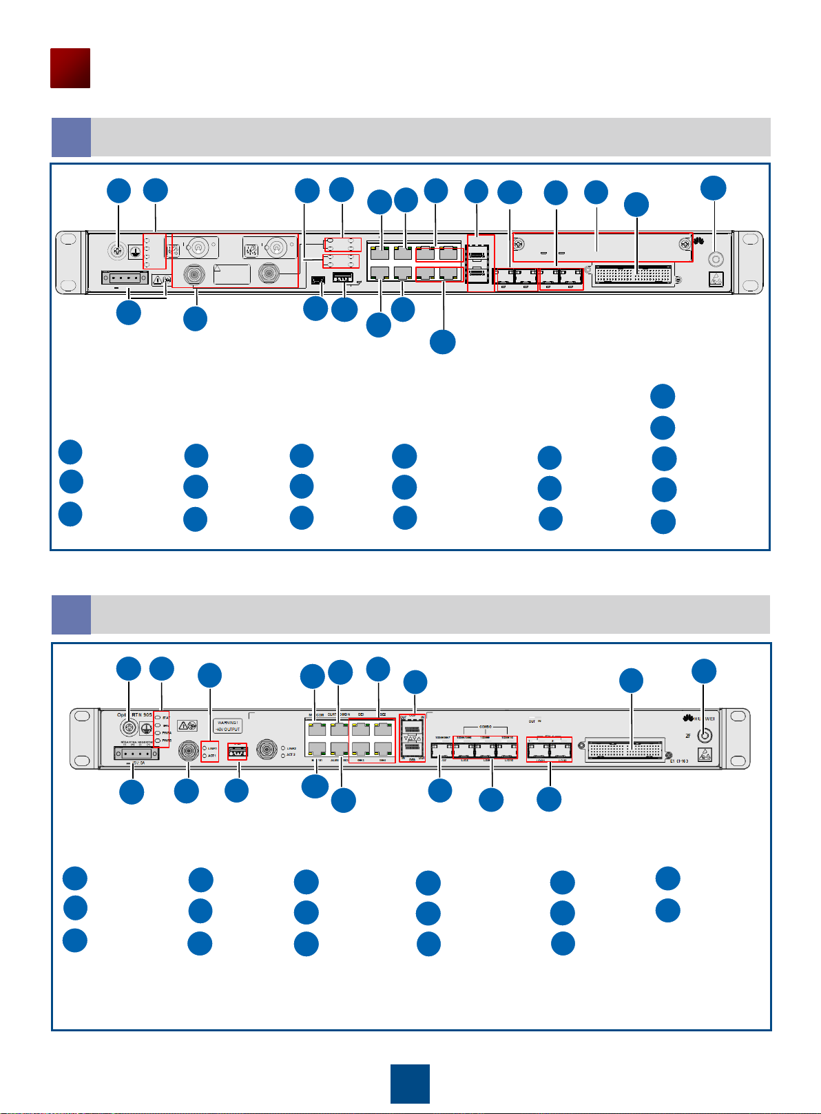
Introduction to the IDU 905 Equipment
Ports on the IDU 905 1A
1
Ground screw
DC-C power socket (Caution!
See "Precautions for
Handling Power Cables.")
NE status indicator
USB port
FE/GE service electrical
ports (RJ-45 connectors)
GE/FE service ports
(SFP modules)
TDM service
concatenation ports
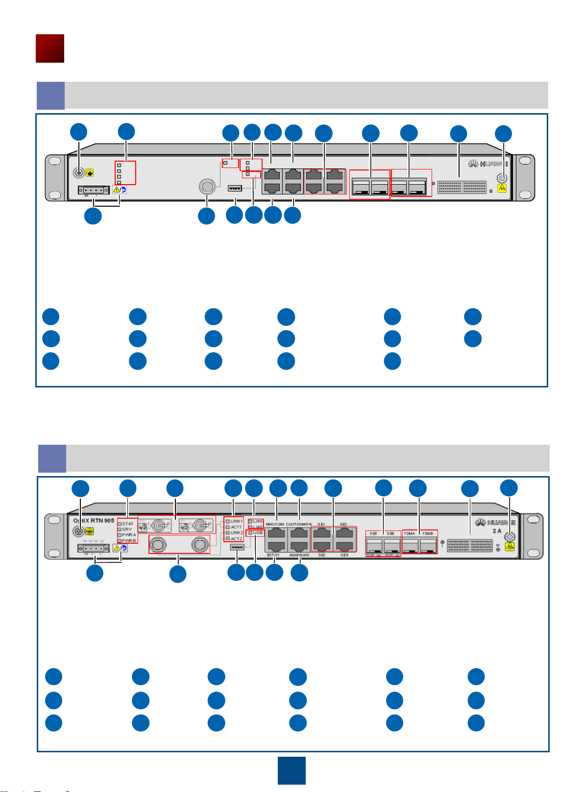
Ports on the IDU 905 2A
2
1
234
5678910111316
17
1
235
IF port to the ODU
6
Radio link status
indicator
7
8
Status indicators of
the GE/FE service
ports (SFP modules)
9
USB port status
indicator
10
11
12
NMS port/NMS
serial port
NE cascading
port/Asynchronous data port
Clock port (CLK)/High-precision
time port (TOD)/Outdoor cabinet
monitoring port (MON)
16
17
16xE1 ports
Port for the ESD wrist
strap
Ground screw
DC-C power socket (Caution!
See "Precautions for
Handling Power Cables.")
NE status indicator
ODU power switch USB port
FE/GE service electrical
ports (RJ-45 connectors)
GE/FE service ports
(SFP modules)
TDM service
concatenation ports
1
2
3
45678
9
10
11
12
13
141516
17
18
123
4
5
IF port to the ODU
6
Radio link status
indicator
7
8
Status indicators of
the GE/FE service
ports (SFP modules)
9
USB port status
indicator
10
11
12
NMS port/NMS serial port
NE cascading
port/Asynchronous data port
Clock port (CLK)/High-precision
time port (TOD)/Outdoor cabinet
monitoring port (MON)
14
15
16
17
16xE1 ports
18
Port for the ESD wrist
strap
4
12
Alarm input/output port
13
14
14
15
15
Alarm input/output port
13
9
Ports
Introduction to the IDU 905 Equipment
Ports on the IDU 905 1C
3
Ground screw
DC-C power socket (Caution!
See "Precautions for
Handling Power Cables.")
NE status indicator
USB port
FE/GE service electrical
ports (RJ-45 connectors)
GE/FE service ports
(SFP modules)
TDM service
concatenation ports
1
235
IF port to the ODU/
XPIC input/output
ports
6
Radio link status
indicator
7
8
Status indicators of
the GE/FE service
ports (SFP modules)
9
USB port status
indicator
10
11
12
NMS port/NMS
serial port
NE cascading port/
Asynchronous data port
Clock port (CLK)/High-precision
time port (TOD)/Outdoor cabinet
monitoring port (MON)
16
17
16xE1 ports
4
Alarm input/output port
13
14
15
12345678910111316
12
141517
Port for the ESD wrist
strap
STM-1 service ports
1+1/TDM service
concatenation ports
Ports on the IDU 905 1E
4
Ground screw
DC-C power socket (Caution!
See "Precautions for
Handling Power Cables.")
NE status indicator
123
Mini USB port
FE/GE service electrical
ports (RJ-45 connectors)
GE/FE service ports
(SFP modules)
STM-1 service ports
5
IF port to the ODU/
XPIC input/output
ports
6
Radio link status
indicator
7
8
Status indicators of
the GE/FE service
ports (SFP modules)
9
USB port/Status
indicator
10
11
12
NMS port/NMS serial
port
NE cascading
port/Asynchronous
data port
Clock port (CLK)/High-precision
time port (TOD)/Outdoor cabinet
monitoring port (MON)
16
17
16xE1 ports
4
Alarm input/output port
131415
COMBO ports
Port for the ESD wrist
strap
MN1 subboard
LINK
L/A5
L/A6
OptiX RTN 905
STAT
SRV
PWRA
PWRB
(+)
(-)
(-)
NEGA
RTNA NEGB RTNB
(+)
-48V;5A
OAM
USB
CLK/TOD/MON
GE2
GE1
GE3
ALMI/ALMO GE4
NMS/COM
EXT/S1
GE5
OUT IN
IN OUT
GE6
MN1
1—COMBO—2
STAT SRV
1—STM-1—2
OUT
OUT
OUT
OUT
OUT
OUT
OUT
LOS1L/A7 L/A7
IN
IN
IN IN
LOS2
E1(1-16)
HUAWEI
1E
WARNING
-48V OUTPUT
TURN OFF POWER BEFORE
DISCONNECTING IF CABLE
!
ACT
123
4
56789
10
11
13
161214
15
17
18
19
18
19
18
19
18
19
10
Ports
Introduction to the IDU 905 Equipment
Ports on the IDU 905 2E
5
Ground screw
DC-C power socket (Caution!
See "Precautions for
Handling Power Cables.")
NE status indicator
1
2
3
Mini USB port
5
IF ports to the ODU/
ODU switches
6
Radio link status
indicator
7
8
Status indicators of
the GE/FE service
ports (SFP modules)
9
USB port/Status
indicator
10
11
12
NMS port/NMS serial
port
NE cascading port/
Asynchronous data port
Clock port (CLK)/High-precision
time port (TOD)/Outdoor cabinet
monitoring port (MON)
4
Alarm input/output port
Power over Ethernet
port
GE/FE service ports
(SFP modules)
STM-1 service ports
16
17
16xE1 ports
13
14
15
COMBO ports
Port for the ESD wrist
strap
MN1 subboard
FE/GE service electrical
ports (RJ-45 connectors)
LINK1
LINK2
ACT1
ACT2
L/A5
L/A6
P1
P2
OptiX RTN 905
STAT
SRV
PWRA
PWRB
(+)
(-)
(-)
NEGA
RTNA NEGB RTNB
(+)
-48V;8A
WARNING
-48V OUTPUT
TURN OFF POWER BEFORE
DISCONNECTING IF CABLE
!
ODU1
PULL
ON
ODU2
PULL
ON OFF
OFF
OAM
USB
CLK/TOD/MON
GE3
GE1/P1 GE2/P2
ALMI/ALMO GE4
NMS/COM
EXT/S1
GE5
OUT IN
IN OUT
GE6
MN1
1—COMBO—2
STAT SRV
1—STM-1—2
OUT
OUT
OUT
OUT
OUT
OUT
OUT
LOS1L/A7 L/A7
IN
IN
IN IN
LOS2
E1(1-16)
HUAWEI
2E
1
2345678
910111316
12
141517
19
18
20
20
18
19
123
123
4
567
9
10
11
161217
567
8
9
10
11
12
4
161713
14
15
8
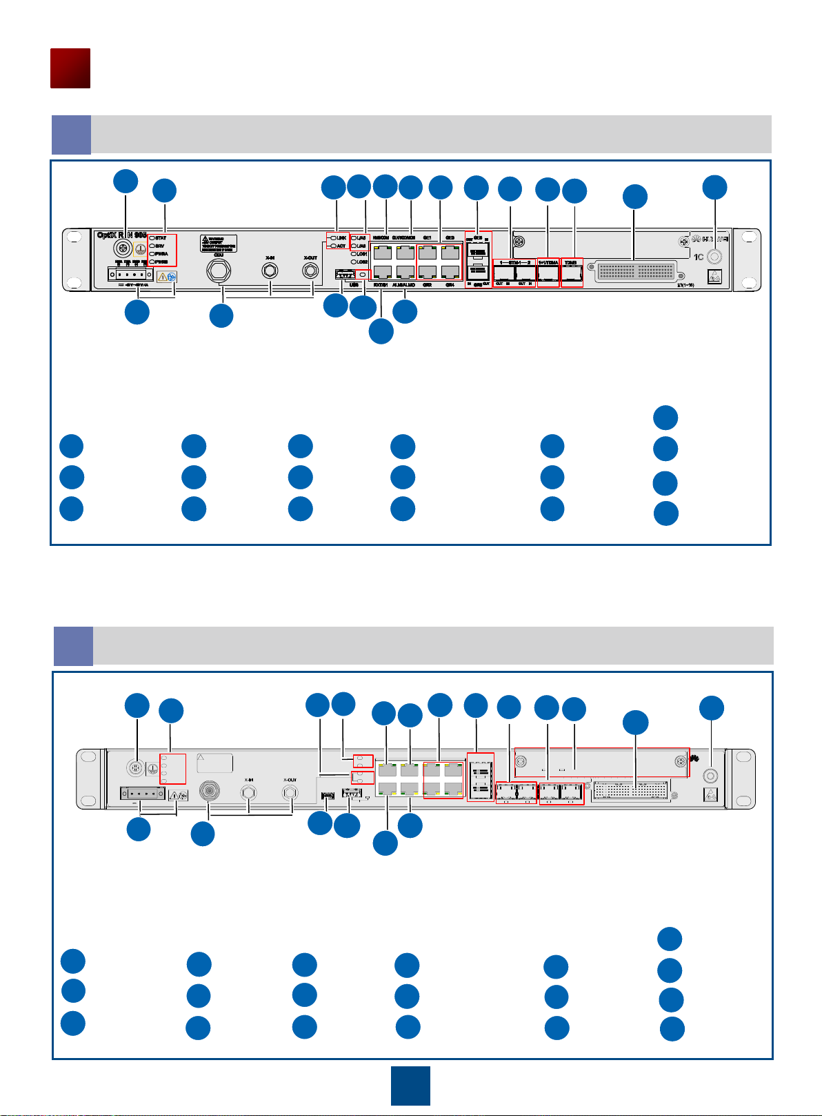
Ports on the IDU 905 2F
6
13
14
15
Ground screw
DC-C power socket (Caution!
See "Precautions for
Handling Power Cables.")
NE status indicator
Mini USB port
IF ports to the ODU/
ODU switches
Radio link status
indicator
NE cascading port/
Asynchronous data port
NMS port/NMS serial
port
Clock port (CLK)/Highprecision time port
(TOD)/Outdoor cabinet
monitoring port (MON)
Alarm input/output port
GE/FE service ports
(SFP modules)
COMBO ports
10GE service ports
(SFP/SFP+ modules)
STM-1 service ports
16xE1 ports
Port for the ESD wrist
strap
Ethernet electrical port
 Loading...