

Huawei RTN 360 V100 Quick Installation Manual
01
RTN 360 V100
Quick Installation Guide
Date: 2014-02-15
Huawei Technologies Co., Ltd.
Address: Huawei Industrial Base
Bantian, Longgang
Shenzhen 518129
People's Republic of China
Website:
http://www.huawei.com
Email: support@huawei.com
No part of this document may be reproduced or transmitted in any form or by any means without prior
written consent of Huawei Technologies Co., Ltd.
Copyright © Huawei Technologies Co., Ltd. 2014. All rights reserved.
02/03 >>
Safety Precautions
Thunderstorms
Do not work with electrical current or work in elevated or exposed locations during a thunderstorm.
Extreme weather conditions
RTN 360 is usually installed outdoors. If weather conditions are extreme during an installation,
personnel should follow the related local guidelines and regulations to safeguard personal health
and safety.
Microwave
High-power radio frequency signals are harmful. Avoid ex posure to transmission from the antennas of
microwave equipment that has the radiation warning symbol ( ). When you are installing or
performing maintenance on an antenna located on a tower that has multiple antennas, avoid exposure
to radiation from other antennas.
Elevated locations
RTN 360 is usually installed in an elevated location, for example, on the rooftop of a building. For installation
in elevated locations, installation personnel must:
• Have the proper training and qualifications, and meet health requirements.
• Wear helmets, safety belts, and anti-slip footwear.
• Wear clothing and gloves appropriate to weather conditions.
• Work in teams of two or more.
• Test hoisting tools before use.
• Avoid installation during extreme weather conditions, such as during thunderstorms, blizzards, or gales.
In addition, all site visitors must wear helmets.
High temperature
If the ambient temperature reaches 55°C, the surface temperature of an RTN 360 may exceed 70°C.
Therefore, wear protective gloves when handling the RTN 360. A high-temperature warning label
( ) is attached to each RTN 360.
Corrosion
Anti-corrosion measures are required if an RTN 360 is installed in a location that is prone to corrosion. Contact the
local Huawei office for details. A location is prone to corrosion if it is:
•Within 3.7 km of an ocean or a salt water lake
• Within 3 km of a heavy pollution source, such as a smelting factory or coal mine
• Within 2 km of a medium pollution source, such as a chemical, rubber, or electroplating plant
• Within 1 km of a light pollution source, such as a food/leather processing plant or heating boiler
Port protection
• Fasten PG covers onto the network ports of an RTN
360, and protect unused ports with caps.
• Retain removed caps for future use.
Caps
Unpacking
• After unpacking an RTN 360, power it on within 24 hours.
• Do not power off an RTN 360 for more than 24 hours during maintenance.
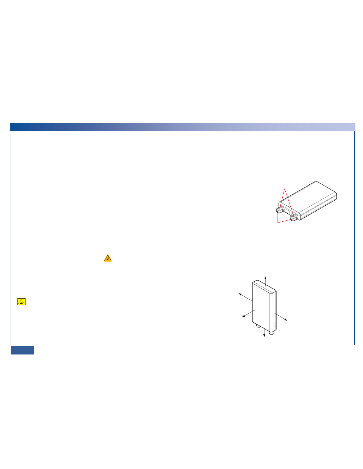
Minimal installation space
The following figure illustrates the minimal installation space required for an RTN 360.
≥ 300 mm
≥ 300 mm
≥ 500 mm
≥ 500 mm
Ensure that the signal
transmission path leading
from the front of an RTN 360
to its peer is unobstructed.
Handling of RTN 360 or mounting kits
Wear clean gloves when handling the RTN 360 or mounting kits.
PG covers
A
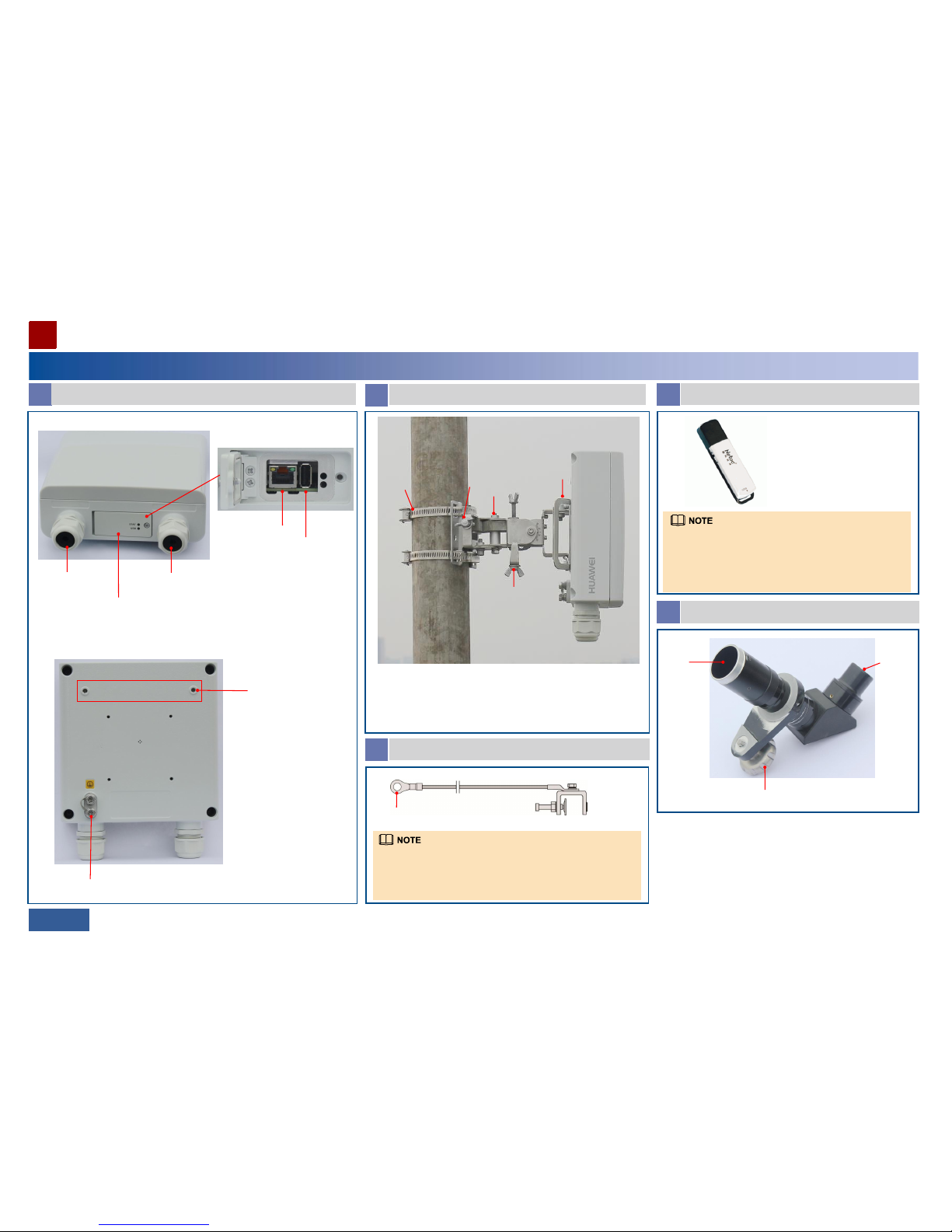
Appearance and ports
Equipment Components
Installing an RTN 360
04/05 >>
Port P&E (receiving both
services and power
signals)
Port GE(e)
B
Mounting kits
1. Attachment plate (installed before delivery)
2. Hose clamp (used when an RTN 360 is installed on a pole)
3. Azimuth adjustment nut
4. Fastener (with holes used for installing an RTN 360 on a wall or pole)
5. Elevation adjustment nut
Maintenance
compartment
RSSI/NMS port
USB port
Inside the maintenance compartment
Holes for mounting an
alignment scope
Ground screw
Front view
Rear view
D
USB flash drive
• The recommended USB flash drive is a 4 GB Netac U208. If a
different model or capacity is required, contact the local Huawei
office. USB flash drives not meeting requirements may be
incompatible.
• The appearance of the shipped USB flash drive may differ from
that shown here.
E
Alignment scope
Mounting frame
Lens
Eyepiece
OT terminal
C
Ground cable
• The ground terminal can connect to a ground bar or U-shaped ground
clip.
• For information about how to connect the ground terminal to a Ushaped ground clip, see the usage description document supplied with
the clip.
Ground terminal
1
2
3
5
4
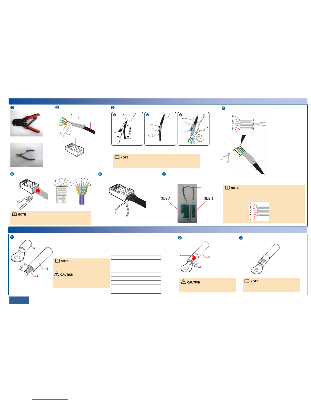
Terminating an Outdoor Network Cable with Shielded RJ45 Connectors
06/07 >>
Prepare the following tools.
RJ45 connector crimping tool
Diagonal pliers
Prepare an outdoor network cable
and shielded RJ45 connectors.
1. Core wire
2. Aluminum foil
3. Braid shield
4. Outer jacket
5. Shielded RJ45 connector
Strip the cable.
Length of the stripped
cable: 20 mm
Strip off the braid shield and cut
the aluminum foil and unwanted
materials.
When stripping off the outer jacket, take care not to damage the braid shield
or aluminum foil.
Remove the outer jacket.
Arrange the core wires according to the pin assignments and cut them
neatly (exposing a length of 12 mm).
12 mm
Cut the core wires neatly.
Length of each exposed core wire: 12 mm
8: brown
7: white and brown
6: green
5: white and blue
4: blue
3: white and green
2: orange
1: white and orange
Insert the arranged core wires into an RJ45 connector according to the pin
assignments and crimp the connector with the crimping tool.
Pin assignments of an RJ45 connector
Crimp the RJ45
connector.
Cut off the exposed braid shield and materials
along the edge of the connector.
Cut off the exposed braid
shield and materials.
Outdoor network
cable
Terminate a connector on the other end of the network cable, and then test the cable
for continuity using a network cable tester.
The pin assignments of the connectors at the two ends must be the same. Outdoor
network cables are straight-through cables.
Terminating a Ground Cable with an OT Terminal
Strip the ground cable.
A: OT terminal
B: ground cable
C: exposed cable conductor
L1: length of the exposed cable
When you are skillful, you can determine L1
based on the length of the OT terminal lug.
When striping off the insulation layer of the
ground cable, take care not to damage or nick
the metal conductor of the cable.
Before crimping, ensure that the core wires are fully inserted in the RJ45
connector.
Fit the exposed cable into the OT terminal.
Ensure that the cable conductor does not
protrude more than 2 mm from the OT terminal.
Crimp the OT terminal lug.
The impression left from crimping the lug may
differ depending on the crimping tool used.
Mapping between the cross-sectional area of a
cable conductor (C) and the length of an exposed
cable (L1)
Cross-sectional
Area of C (mm2)
L1 (mm)
1
1.5
2.5
4
6
10
16
25
35
50
7
7
7
8
9
11
13
14
16
16
Crimp the OT
terminal lug.
Generally, straight-through cables are used with the RTN 360.
Crossover cables are required only when the BTS3902E and BTS3202E
supplies power over Ethernet to the RTN 360. In this case, the pin
assignments of the connector at the other end are as follows:
8: brown
7: white and brown
6: orange
5: white and blue
4: blue
3: white and orange
2: green
1: white and green
 Loading...