

Page 1

Quidway S9300 Terabit Routing Switch
V100R001C03
Configuration Guide - IP Service
Issue 02
Date 2009-08-06
Huawei Proprietary and Confidential
Copyright © Huawei Technologies Co., Ltd.
Page 2

Huawei Technologies Co., Ltd. provides customers with comprehensive technical support and service. For any
assistance, please contact our local office or company headquarters.
Huawei Technologies Co., Ltd.
Address: Huawei Industrial Base
Bantian, Longgang
Shenzhen 518129
People's Republic of China
Website: http://www.huawei.com
Email: support@huawei.com
Copyright © Huawei Technologies Co., Ltd. 2009. All rights reserved.
No part of this document may be reproduced or transmitted in any form or by any means without prior written
consent of Huawei Technologies Co., Ltd.
Trademarks and Permissions
and other Huawei trademarks are the property of Huawei Technologies Co., Ltd.
All other trademarks and trade names mentioned in this document are the property of their respective holders.
Notice
The information in this document is subject to change without notice. Every effort has been made in the
preparation of this document to ensure accuracy of the contents, but the statements, information, and
recommendations in this document do not constitute a warranty of any kind, express or implied.
Huawei Proprietary and Confidential
Copyright © Huawei Technologies Co., Ltd.
Page 3

Quidway S9300 Terabit Routing Switch
Configuration Guide - IP Service Contents
Contents
About This Document.....................................................................................................................1
1 IP Address Configuration.........................................................................................................1-1
1.1 Introduction to IP Addresses...........................................................................................................................1-2
1.2 IP Address Features Supported by the S9300.................................................................................................1-2
1.3 Assigning IP Addresses to Interfaces..............................................................................................................1-2
1.3.1 Establishing the Configuration Task......................................................................................................1-2
1.3.2 Setting a Primary IP Address for an Interface........................................................................................1-3
1.3.3 (Optional) Setting a Secondary IP Addresses for an Interface...............................................................1-4
1.3.4 Checking the Configuration...................................................................................................................1-4
1.4 Setting Unnumbered IP Addresses..................................................................................................................1-4
1.4.1 Establishing the Configuration Task......................................................................................................1-5
1.4.2 Setting the Primary IP Address..............................................................................................................1-5
1.4.3 Setting the Unnumbered IP Address......................................................................................................1-6
1.4.4 Checking the Configuration...................................................................................................................1-6
1.5 Configuration Examples..................................................................................................................................1-7
1.5.1 Example for Setting Primary and Secondary IP Addresses...................................................................1-7
1.5.2 Example for Configuring a Tunnel Interface to Borrow the IP Address of a Loopback Interface........1-9
2 DHCP Configuration.................................................................................................................2-1
2.1 Introduction to DHCP.....................................................................................................................................2-2
2.2 DHCP Features Supported by the S9300........................................................................................................2-2
2.3 Configuring the DHCP Relay Agent...............................................................................................................2-2
2.3.1 Establishing the Configuration Task......................................................................................................2-2
2.3.2 Configuring a DHCP Server Group.......................................................................................................2-3
2.3.3 Enabling DHCP Relay...........................................................................................................................2-4
2.3.4 Binding an Interface to a DHCP Server Group......................................................................................2-4
2.3.5 Checking the Configuration...................................................................................................................2-5
2.4 Configuring the S9300 to Request the DHCP Server to Release an IP Address of a Client..........................2-5
2.4.1 Establishing the Configuration Task......................................................................................................2-5
2.4.2 Configuring the S9300 to Request the DHCP Server to Release an IP Address of a Client.................2-6
2.4.3 Checking the Configuration...................................................................................................................2-7
2.5 Maintaining DHCP..........................................................................................................................................2-7
2.5.1 Clearing DHCP Statistics.......................................................................................................................2-7
Issue 02 (2009-08-06) Huawei Proprietary and Confidential
Copyright © Huawei Technologies Co., Ltd.
i
Page 4

Quidway S9300 Terabit Routing Switch
Contents
2.5.2 Monitoring the Running Status of DHCP..............................................................................................2-7
2.6 Configuration Examples..................................................................................................................................2-8
2.6.1 Example for Configuring the DHCP Relay Agent.................................................................................2-8
2.6.2 Example for Configuring the DHCP Relay in a Super VLAN............................................................2-10
Configuration Guide - IP Service
3 IP Performance Configuration.................................................................................................3-1
3.1 IP Performance Supported by the S9300........................................................................................................3-2
3.2 Optimizing IP Performance.............................................................................................................................3-2
3.2.1 Establishing the Configuration Task......................................................................................................3-2
3.2.2 Enabling an Interface to Check the Source IP Addresses of Packets.....................................................3-3
3.2.3 Configuring Forcible Fragmentation of Outgoing Packets on an Interface...........................................3-4
3.2.4 Setting ICMP Parameters.......................................................................................................................3-4
3.2.5 Setting TCP Parameters.........................................................................................................................3-6
3.2.6 Setting the Load Balancing Mode of IP Packet Forwarding..................................................................3-7
3.2.7 Checking the Configuration...................................................................................................................3-7
3.3 Maintaining IP Performance...........................................................................................................................3-8
3.3.1 Clearing IP Performance Statistics.........................................................................................................3-8
3.3.2 Monitoring the Running Status of IP Performance................................................................................3-9
3.3.3 Debugging IP Performance..................................................................................................................3-10
3.4 Configuration Examples................................................................................................................................3-11
3.4.1 Example for Disabling the Sending of ICMP Redirection Packets.....................................................3-11
3.4.2 Example for Configuring ICMP Host Unreachable Packets................................................................3-14
3.4.3 Example for Optimizing System Performance by Discarding Certain ICMP Packets........................3-16
4 IP Unicast PBR Configuration.................................................................................................4-1
4.1 Introduction to IP Unicast PBR.......................................................................................................................4-2
4.2 IP Unicast PBR Features Supported by the S9300.........................................................................................4-2
4.3 Configuring IP Unicast PBR...........................................................................................................................4-2
4.3.1 Establishing the Configuration Task......................................................................................................4-2
4.3.2 Defining Matching Rules for PBR.........................................................................................................4-3
4.3.3 Defining Actions of PBR.......................................................................................................................4-4
4.3.4 Applying a Policy-based Route..............................................................................................................4-5
4.3.5 Checking the Configuration...................................................................................................................4-6
4.4 Maintaining IP Unicast PBR...........................................................................................................................4-6
4.4.1 Monitoring the Running Status of IP Unicast PBR................................................................................4-6
4.4.2 Debugging IP Unicast PBR....................................................................................................................4-7
4.5 Configuration Examples..................................................................................................................................4-7
4.5.1 Example for Configuring PBR Based on the Protocol Type.................................................................4-7
4.5.2 Example for Configuring PBR Based on the Packet Length...............................................................4-11
5 UDP Helper Configuration......................................................................................................5-1
5.1 Introduction to UDP Helper............................................................................................................................5-2
5.2 UDP Helper Features Supported by the S9300...............................................................................................5-2
5.3 Configuring UDP Helper................................................................................................................................5-3
ii Huawei Proprietary and Confidential
Copyright © Huawei Technologies Co., Ltd.
Issue 02 (2009-08-06)
Page 5

Quidway S9300 Terabit Routing Switch
Configuration Guide - IP Service Contents
5.3.1 Establishing the Configuration Task......................................................................................................5-3
5.3.2 Enabling the UDP Helper Function.......................................................................................................5-4
5.3.3 (Optional) Configuring the UDP Port on Which Packets Are Forwarded.............................................5-4
5.3.4 Configuring the Destination Server for Packet Relay............................................................................5-5
5.3.5 Checking the Configuration...................................................................................................................5-5
5.4 Maintaining UDP Helper................................................................................................................................5-6
5.4.1 Clearing UDP Helper Statistics..............................................................................................................5-6
5.4.2 Monitoring the Running Status of UDP Helper.....................................................................................5-6
5.5 Configuration Examples..................................................................................................................................5-6
5.5.1 Example for Configuring UDP Helper...................................................................................................5-7
Issue 02 (2009-08-06) Huawei Proprietary and Confidential
Copyright © Huawei Technologies Co., Ltd.
iii
Page 6

Page 7

Quidway S9300 Terabit Routing Switch
Configuration Guide - IP Service Figures
Figures
Figure 1-1 Networking diagram for setting IP addresses.....................................................................................1-7
Figure 1-2 Networking diagram for configuring a tunnel interface to borrow an IP address of a loopback interface
...............................................................................................................................................................................1-9
Figure 2-1 Networking diagram for configuring the DHCP relay agent..............................................................2-8
Figure 2-2 Networking diagram for configuring the DHCP relay in a super VLAN.........................................2-11
Figure 3-1 Networking diagram for disabling the sending of ICMP redirection packets..................................3-11
Figure 3-2 Networking diagram for disabling the sending of ICMP host unreachable packets........................3-14
Figure 3-3 Networking for configuring ICMP security function.......................................................................3-17
Figure 4-1 Networking diagram for configuring PBR based on the protocol type..............................................4-8
Figure 4-2 Networking diagram for configuring PBR based on the packet length............................................4-11
Figure 5-1 Networking diagram for configuring UDP helper..............................................................................5-7
Issue 02 (2009-08-06) Huawei Proprietary and Confidential
Copyright © Huawei Technologies Co., Ltd.
v
Page 8

Page 9

Quidway S9300 Terabit Routing Switch
Configuration Guide - IP Service Tables
Tables
Table 4-1 Relations between values and keywords..............................................................................................4-5
Table 5-1 Lists of default UDP ports on which packets are forwarded after the UDP helper function is enabled
...............................................................................................................................................................................5-2
Issue 02 (2009-08-06) Huawei Proprietary and Confidential
Copyright © Huawei Technologies Co., Ltd.
vii
Page 10

Page 11
Quidway S9300 Terabit Routing Switch
Configuration Guide - IP Service About This Document
About This Document
Purpose
This document describes the configurations of the IP services of the S9300, including the basic
knowledge and configurations of secondary IP addresses, DHCP, IP performance, IP unicast
policy-based routing, UDP Helper, . By reading this document, you can learn the concepts and
configuration procedures of IP services.
Related Versions
The following table lists the product versions related to this document.
Product Name
S9300 V100R001C03
Intended Audience
This document is intended for:
l Policy planning engineers
l Installation and commissioning engineers
l NM configuration engineers
l Technical support engineers
Organization
Version
This document is organized as follows.
Chapter
1 IP Address Configuration Describes the general procedure for setting IP addresses.
2 DHCP Configuration Describes the principle of DHCP and provides configuration
Issue 02 (2009-08-06) Huawei Proprietary and Confidential
Copyright © Huawei Technologies Co., Ltd.
Description
procedures and examples of DHCP.
1
Page 12
DANGER
WARNING
CAUTION
TIP
NOTE
About This Document
Quidway S9300 Terabit Routing Switch
Configuration Guide - IP Service
Chapter Description
3 IP Performance
Configuration
4 IP Unicast PBR
Configuration
5 UDP Helper
Configuration
Conventions
Symbol Conventions
The symbols that may be found in this document are defined as follows.
Symbol Description
Describes the principle of IP performance and provides
configuration procedures and examples of IP performance.
Describes the principle of IP unicast PBR and provides
configuration procedures and examples of IP unicast PBR.
Describes the principle of UDP helper and provides
configuration procedures and examples of UDP helper.
Indicates a hazard with a high level of risk, which if not
avoided, will result in death or serious injury.
General Conventions
The general conventions that may be found in this document are defined as follows.
Convention
Times New Roman Normal paragraphs are in Times New Roman.
Boldface Names of files, directories, folders, and users are in
Indicates a hazard with a medium or low level of risk, which
if not avoided, could result in minor or moderate injury.
Indicates a potentially hazardous situation, which if not
avoided, could result in equipment damage, data loss,
performance degradation, or unexpected results.
Indicates a tip that may help you solve a problem or save
time.
Provides additional information to emphasize or supplement
important points of the main text.
Description
boldface. For example, log in as user root.
Italic Book titles are in italics.
2 Huawei Proprietary and Confidential
Copyright © Huawei Technologies Co., Ltd.
Issue 02 (2009-08-06)
Page 13
Quidway S9300 Terabit Routing Switch
Configuration Guide - IP Service About This Document
Convention Description
Courier New
Command Conventions
The command conventions that may be found in this document are defined as follows.
Convention Description
Boldface The keywords of a command line are in boldface.
Italic Command arguments are in italics.
[ ] Items (keywords or arguments) in brackets [ ] are optional.
{ x | y | ... } Optional items are grouped in braces and separated by
[ x | y | ... ] Optional items are grouped in brackets and separated by
{ x | y | ... }
Examples of information displayed on the screen are in
Courier New.
vertical bars. One item is selected.
vertical bars. One item is selected or no item is selected.
*
Optional items are grouped in braces and separated by
vertical bars. A minimum of one item or a maximum of all
items can be selected.
[ x | y | ... ]
&<1-n> The parameter before the & sign can be repeated 1 to n times.
# A line starting with the # sign is comments.
GUI Conventions
The GUI conventions that may be found in this document are defined as follows.
Convention
Boldface Buttons, menus, parameters, tabs, window, and dialog titles
> Multi-level menus are in boldface and separated by the ">"
Keyboard Operations
*
Optional items are grouped in brackets and separated by
vertical bars. Several items or no item can be selected.
Description
are in boldface. For example, click OK.
signs. For example, choose File > Create > Folder.
The keyboard operations that may be found in this document are defined as follows.
Issue 02 (2009-08-06) Huawei Proprietary and Confidential
Copyright © Huawei Technologies Co., Ltd.
3
Page 14
About This Document
Format Description
Key Press the key. For example, press Enter and press Tab.
Key 1+Key 2 Press the keys concurrently. For example, pressing Ctrl+Alt
Key 1, Key 2 Press the keys in turn. For example, pressing Alt, A means
Mouse Operations
The mouse operations that may be found in this document are defined as follows.
Action Description
Click Select and release the primary mouse button without moving
Quidway S9300 Terabit Routing Switch
Configuration Guide - IP Service
+A means the three keys should be pressed concurrently.
the two keys should be pressed in turn.
the pointer.
Double-click Press the primary mouse button twice continuously and
Drag Press and hold the primary mouse button and move the
Update History
Updates between document issues are cumulative. Therefore, the latest document issue contains
all updates made in previous issues.
Updates in Issue 02 (2009-08-06)
Based on issue 01 (2009-07-28), the document is updated as follows:
The following information is modified: The link to 1 IP Address Configuration is corrected.
Updates in Issue 01 (2009-07-28)
Initial commercial release.
quickly without moving the pointer.
pointer to a certain position.
4 Huawei Proprietary and Confidential
Copyright © Huawei Technologies Co., Ltd.
Issue 02 (2009-08-06)
Page 15

Quidway S9300 Terabit Routing Switch
Configuration Guide - IP Service 1 IP Address Configuration
1 IP Address Configuration
About This Chapter
This chapter describes the concept and configuration procedures of the IP addresses on the
S9300.
1.1 Introduction to IP Addresses
This section describes the concept of IP addresses.
1.2 IP Address Features Supported by the S9300
This section describes the methods for setting the IP addresses for the S9300.
1.3 Assigning IP Addresses to Interfaces
This section describes the procedure for assigning the IP addresses to interfaces.
1.4 Setting Unnumbered IP Addresses
This section describes how to configure a tunnel interface to use the address of the loopback
interface.
1.5 Configuration Examples
This section provides several examples of IP address configuration.
Issue 02 (2009-08-06) Huawei Proprietary and Confidential
Copyright © Huawei Technologies Co., Ltd.
1-1
Page 16

Quidway S9300 Terabit Routing Switch
1 IP Address Configuration
Configuration Guide - IP Service
1.1 Introduction to IP Addresses
This section describes the concept of IP addresses.
Each host needs an IP address to communicate with each other on an IP network.
An IP address is a 32-bit address used on the Internet. It consists of a network ID and a host ID.
The network ID identifies a network and the host ID identifies a specific network device on the
network. If multiple network devices have the same network ID, they reside on the same network
regardless of their physical locations.
1.2 IP Address Features Supported by the S9300
This section describes the methods for setting the IP addresses for the S9300.
The S9300 supports the following methods for setting IP addresses:
l Setting static IP addresses for interfaces manually
l Configuring an interface to borrow an IP address from other interfaces
To save IP address spaces, the S9300 enables you to configure the address mask of an interface
as 31 bits. In this case, there are two IP addresses on a subnet: the subnet address and the broadcast
address of the subnet. Both the addresses are called host addresses.
1.3 Assigning IP Addresses to Interfaces
This section describes the procedure for assigning the IP addresses to interfaces.
1.3.1 Establishing the Configuration Task
1.3.2 Setting a Primary IP Address for an Interface
1.3.3 (Optional) Setting a Secondary IP Addresses for an Interface
1.3.4 Checking the Configuration
1.3.1 Establishing the Configuration Task
Applicable Environment
To run IP services on an interface, you need to set an IP address for the interface. Each interface
of the S9300 can be assigned with multiple IP addresses, in which one is the primary IP address
and the others are secondary IP addresses.
Generally, only one IP address, namely, the primary IP address, is required for an interface. In
special cases, the secondary IP addresses need to be set for the interface. For example, the
S9300 is connected to a physical network through an interface. The hosts on this physical
network belong to two Class C networks. In this case, you need to set a primary IP address and
a secondary IP address on the interface of the S9300. The S9300 can then communicate with all
the hosts on the physical network.
1-2 Huawei Proprietary and Confidential
Copyright © Huawei Technologies Co., Ltd.
Issue 02 (2009-08-06)
Page 17
Quidway S9300 Terabit Routing Switch
Configuration Guide - IP Service 1 IP Address Configuration
Pre-configuration Tasks
Before setting an IP address for an interface, complete the following tasks:
l Connecting interfaces and setting the physical parameters of each interface to make the
physical layer in Up state
l Setting parameters of the link layer protocol for interfaces and ensuring that the status of
the link layer protocol on the interfaces is Up
Data Preparation
To set an IP address for an interface, you need the following data.
No. Data
1 Interface number
2 IP address and subnet mask of the interface
3 (Optional) Secondary IP address and subnet
mask of the interface
1.3.2 Setting a Primary IP Address for an Interface
Context
Do as follows on the S9300.
Procedure
Step 1 Run:
system-view
The system view is displayed.
Step 2 Run:
interface interface-type interface-number
The interface view is displayed.
Step 3 Run:
ip address ip-address { mask | mask-length }
The IP address of the interface is set.
One interface has only one primary IP address. If a primary IP address is already set on an
interface when a new primary IP address is set, the original primary IP address is deleted and
the new primary IP address takes effect.
----End
Issue 02 (2009-08-06) Huawei Proprietary and Confidential
Copyright © Huawei Technologies Co., Ltd.
1-3
Page 18

Quidway S9300 Terabit Routing Switch
1 IP Address Configuration
Configuration Guide - IP Service
1.3.3 (Optional) Setting a Secondary IP Addresses for an Interface
Context
Do as follows on the S9300.
Procedure
Step 1 Run:
system-view
The system view is displayed.
Step 2 Run:
interface interface-type interface-number
The interface view is displayed.
Step 3 Run:
ip address ip-address { mask | mask-length } sub
The secondary IP address of the interface is set.
The secondary IP address with a 31-bit mask can be set for the interface.
Each interface supports up to 31 secondary IP addresses.
NOTE
The primary and secondary IP addresses of the same interface or different secondary IP addresses of the
same interface cannot be in the same network segment.
----End
1.3.4 Checking the Configuration
Context
All configurations are complete.
Procedure
Step 1 Run the display ip interface [ interface-type interface-number ] command to view the settings
of IP addresses on the interface.
Step 2 Run the display ip interface brief [ interface-type [ interface-number ] ] command to view brief
information about IP addresses on the interface.
----End
1.4 Setting Unnumbered IP Addresses
This section describes how to configure a tunnel interface to use the address of the loopback
interface.
1.4.1 Establishing the Configuration Task
1.4.2 Setting the Primary IP Address
1-4 Huawei Proprietary and Confidential
Copyright © Huawei Technologies Co., Ltd.
Issue 02 (2009-08-06)
Page 19
Quidway S9300 Terabit Routing Switch
Configuration Guide - IP Service 1 IP Address Configuration
1.4.3 Setting the Unnumbered IP Address
1.4.4 Checking the Configuration
1.4.1 Establishing the Configuration Task
Applicable Environment
In certain application environment, an interface needs to be configured to borrow an IP address
from another interface, thus saving IP addresses. Sometimes, an interface that is rarely used can
be configured to borrow an IP address from another interface. Configuring such interface with
a fixed IP address is unnecessary.
At present, the S9300 only allows the tunnel interface to borrow the IP address of the loopback
interface.
Pre-configuration Tasks
Before configuring an unnumbered address for an interface, complete the following tasks:
l Setting the physical attributes of the interface that borrows an IP address and the interface
l Setting the link layer protocol of the interface that borrows an IP address and the interface
Data Preparation
To set an unnumbered IP address for an interface, you need the following data.
No.
1 Number, IP address, and mask of the interface
2 Number of the interface that borrows an IP
that lends an IP address
that lends an IP address
Data
that lends an IP address
address
NOTE
This section describes only the configuration of IP address unnumbered.
Because the interface that borrows an IP address does not have an IP address itself, the dynamic routing
protocol cannot be enabled on such an interface. Therefore, you must manually set a static route to the
remote network segment to implement the interconnection between S9300s.
1.4.2 Setting the Primary IP Address
Context
Do as follows on the S9300.
Issue 02 (2009-08-06) Huawei Proprietary and Confidential
Copyright © Huawei Technologies Co., Ltd.
1-5
Page 20

1 IP Address Configuration
Procedure
Step 1 Run:
system-view
The system view is displayed.
Step 2 Run:
interface interface-type interface-number
The interface view is displayed.
Step 3 Run:
ip address ip-address { mask | mask-length }
The primary IP address of the interface is set.
----End
1.4.3 Setting the Unnumbered IP Address
Quidway S9300 Terabit Routing Switch
Configuration Guide - IP Service
Context
Do as follows on the S9300.
Procedure
Step 1 Run:
system-view
The system view is displayed.
Step 2 Run:
interface interface-type interface-number
The interface view is displayed.
Step 3 Run:
ip address unnumbered interface interface-type interface-number
The interface is configured to borrow the IP address of a specified interface.
----End
1.4.4 Checking the Configuration
Context
All configurations are complete.
Procedure
Step 1 Run the display ip interface [ interface-type interface-number ] command to view information
about IP addresses on the interface.
1-6 Huawei Proprietary and Confidential
Copyright © Huawei Technologies Co., Ltd.
Issue 02 (2009-08-06)
Page 21
172.16.1.0/24
172.16.2.0/24
S9300
GE 1/0/1
VLANIF 100
172.16.1.1/24
172.16.2.1/24 sub
Quidway S9300 Terabit Routing Switch
Configuration Guide - IP Service 1 IP Address Configuration
Step 2 Run the display ip interface brief [ interface-type [ interface-number ] ] command to view brief
information about the IP address on the interface.
----End
1.5 Configuration Examples
This section provides several examples of IP address configuration.
1.5.1 Example for Setting Primary and Secondary IP Addresses
1.5.2 Example for Configuring a Tunnel Interface to Borrow the IP Address of a Loopback
Interface
1.5.1 Example for Setting Primary and Secondary IP Addresses
Networking Requirements
As shown in Figure 1-1, GE 1/0/1 of the S9300 is connected to a LAN, in which hosts belong
to two different network segments, that is 172.16.1.0/24 and 172.16.2.0/24. It is required that
the S9300 can access the two network segments but the host in 172.16.1.0/24 cannot interconnect
with the host in 172.16.2.0/24.
Figure 1-1 Networking diagram for setting IP addresses
Configuration Roadmap
The configuration roadmap is as follows:
1. Analyze the address of the network segment to which each interface is connected.
2. Set the secondary IP addresses for an interface.
NOTE
Note that the primary and secondary IP addresses of the same interface or different secondary IP addresses
of the same interface cannot be in the same network segment.
Issue 02 (2009-08-06) Huawei Proprietary and Confidential
Copyright © Huawei Technologies Co., Ltd.
1-7
Page 22

1 IP Address Configuration
Data Preparation
To complete the configuration, you need the following data.
l Primary IP address and subnet mask of the interface
l Secondary IP address and subnet mask of the interface
Procedure
Step 1 Set the IP address for VLANIF 100 where GE 1/0/1 of the S9300 belongs.
<Quidway> system-view
[Quidway] vlan 100
[Quidway-Vlan100] quit
[Quidway] interface gigabitethernet 1/0/1
[Quidway-GigabitEthernet1/0/1] port hybrid pvid vlan 100
[Quidway-GigabitEthernet1/0/1] port hybrid untagged vlan 100
[Quidway-GigabitEthernet1/0/1] quit
[Quidway] interface vlanif 100
[Quidway-Vlanif100] ip address 172.16.1.1 24
[Quidway-Vlanif100] ip address 172.16.2.1 24 sub
Step 2 Verify the configuration.
Quidway S9300 Terabit Routing Switch
Configuration Guide - IP Service
# Ping a host on network segment 172.16.2.0 from S9300. The ping succeeds.
<Quidway> ping 172.16.1.2
PING 172.16.1.2: 56 data bytes, press CTRL_C to break
Reply from 172.16.1.2: bytes=56 Sequence=1 ttl=128 time=25 ms
Reply from 172.16.1.2: bytes=56 Sequence=2 ttl=128 time=27 ms
Reply from 172.16.1.2: bytes=56 Sequence=3 ttl=128 time=26 ms
Reply from 172.16.1.2: bytes=56 Sequence=4 ttl=128 time=26 ms
Reply from 172.16.1.2: bytes=56 Sequence=5 ttl=128 time=26 ms
--- 172.16.1.2 ping statistics -- 5 packet(s) transmitted
5 packet(s) received
0.00% packet loss
round-trip min/avg/max = 25/26/27 ms
Ping a host on network segment 172.16.2.0 from the S9300. The ping succeeds.
<Quidway> ping 172.16.2.2
PING 172.16.2.2: 56 data bytes, press CTRL_C to break
Reply from 172.16.2.2: bytes=56 Sequence=1 ttl=128 time=25 ms
Reply from 172.16.2.2: bytes=56 Sequence=2 ttl=128 time=26 ms
Reply from 172.16.2.2: bytes=56 Sequence=3 ttl=128 time=26 ms
Reply from 172.16.2.2: bytes=56 Sequence=4 ttl=128 time=26 ms
Reply from 172.16.2.2: bytes=56 Sequence=5 ttl=128 time=26 ms
--- 172.16.2.2 ping statistics -- 5 packet(s) transmitted
5 packet(s) received
0.00% packet loss
round-trip min/avg/max = 25/25/26 ms
----End
Configuration Files
Configuration file of the S9300
#
sysname Quidway
#
vlan 100
#
interface Vlanif100
1-8 Huawei Proprietary and Confidential
Copyright © Huawei Technologies Co., Ltd.
Issue 02 (2009-08-06)
Page 23
LoopBack 0
9.9.9.9/32
S9300-B
S9300-A S9300-C
Tunnel
PC 1 PC 2
LoopBack 0
116.116.116.116/32
Tunnel 3/0/15
Tunnel 3/0/15
Quidway S9300 Terabit Routing Switch
Configuration Guide - IP Service 1 IP Address Configuration
ip address 172.16.1.1 255.255.255.0
ip address 172.16.2.1 255.255.255.0 sub
#
interface GigabitEthernet1/0/1
port hybrid pvid vlan 100
port hybrid untagged vlan 100
#
return
1.5.2 Example for Configuring a Tunnel Interface to Borrow the IP Address of a Loopback Interface
Networking Requirements
As shown in Figure 1-2, Tunnel 3/0/15 of S9300-A is connected to S9300-C through a tunnel.
Tunnel 3/0/15 of S9300-A is rarely used. To save IP addresses, configure Tunnel 3/0/15 to
borrow the IP address of Loopback0. Tunnel 3/0/15 of S9300-C borrows the IP address of
Loopback0 of S9300-C.
Figure 1-2 Networking diagram for configuring a tunnel interface to borrow an IP address of a
loopback interface
Configuration Roadmap
The configuration roadmap is as follows:
l Set addresses of the Loopback0 interfaces of S9300-A and S9300-C.
l Configure OSPF.
l Configure Tunnel 3/0/15 of S9300-A to borrow the IP address of Loopback0.
l Configure Tunnel 3/0/15 of S9300-C to borrow the IP address of Loopback0.
Data Preparation
To complete the configuration, you need the following data.
Issue 02 (2009-08-06) Huawei Proprietary and Confidential
Copyright © Huawei Technologies Co., Ltd.
1-9
Page 24

1 IP Address Configuration
l IP address for Loopback0 of S9300-A
l IP address for Loopback0 of S9300-C
l Index for Loopback0 of S9300-A
l Index for Loopback0 of S9300-C
Procedure
Step 1 # Configure S9300-A.
# Set an IP address for Loopback0 of S9300-A.
<Quidway> system-view
[Quidway] sysname S9300-A
[S9300-A] interface loopback 0
[S9300-A-LoopBack0] ip address 116.116.116.116 32
[S9300-A-LoopBack0] quit
Configure OSPF.
[S9300-A] ospf
[S9300-A-ospf-1] area 0
[S9300-A-ospf-1-area-0.0.0.0] network 116.116.116.116 0.0.0.0
[S9300-A-ospf-1-area-0.0.0.0] quit
[S9300-A-ospf-1] quit
Quidway S9300 Terabit Routing Switch
Configuration Guide - IP Service
# Configure Tunnel 3/0/15 to borrow the IP address of Loopback0.
[S9300-A] interface tunnel 3/0/15
[S9300-A-Tunnel3/0/15] ip address unnumbered interface loopback 0
[S9300-A-Tunnel3/0/15] quit
Step 2 Configure S9300-C. The configuration procedure is the same as the configuration procedure of
S9300-A.
Step 3 Verify the configuration.
# Ping 9.9.9.9 on S9300-A.
[S9300-A] ping 9.9.9.9
PING 9.9.9.9: 56 data bytes, press CTRL_C to break
Reply from 9.9.9.9: bytes=56 Sequence=1 ttl=255 time=2 ms
Reply from 9.9.9.9: bytes=56 Sequence=2 ttl=255 time=3 ms
Reply from 9.9.9.9: bytes=56 Sequence=3 ttl=255 time=3 ms
Reply from 9.9.9.9: bytes=56 Sequence=4 ttl=255 time=3 ms
Reply from 9.9.9.9: bytes=56 Sequence=5 ttl=255 time=3 ms
--- 9.9.9.9 ping statistics -- 5 packet(s) transmitted
5 packet(s) received
0.00% packet loss
round-trip min/avg/max = 2/2/3 ms
----End
Configuration Files
l Configuration file of S9300-A
#
sysname S9300-A
#
interface LoopBack0
ip address 116.116.116.116 255.255.225.255
#
interface Tunnel3/0/15
1-10 Huawei Proprietary and Confidential
Copyright © Huawei Technologies Co., Ltd.
Issue 02 (2009-08-06)
Page 25

Quidway S9300 Terabit Routing Switch
Configuration Guide - IP Service 1 IP Address Configuration
ip address unnumbered interface LoopBack0
#
ospf 1
area 0.0.0.0
network 116.116.116.116 0.0.0.0
#
return
l Configuration file of S9300-C
#
sysname S9300-C
#
interface LoopBack0
ip address 9.9.9.9 255.255.225.255
#
interface Tunnel3/0/15
ip address unnumbered interface LoopBack0
#
ospf 1
area 0.0.0.0
network 9.9.9.9 0.0.0.0
#
return
Issue 02 (2009-08-06) Huawei Proprietary and Confidential
Copyright © Huawei Technologies Co., Ltd.
1-11
Page 26

Page 27

Quidway S9300 Terabit Routing Switch
Configuration Guide - IP Service 2 DHCP Configuration
2 DHCP Configuration
About This Chapter
This chapter describes the principle of the Dynamic Host Configuration Protocol (DHCP), and
provides configuration procedures and examples of DHCP.
2.1 Introduction to DHCP
This section describes the principle of DHCP.
2.2 DHCP Features Supported by the S9300
This section describes the DHCP features supported by the S9300.
2.3 Configuring the DHCP Relay Agent
This section describes how to configure the DHCP relay agent so that DHCP requests from
clients can be sent to the DHCP server through the DHCP relay agent across the network
segment.
2.4 Configuring the S9300 to Request the DHCP Server to Release an IP Address of a Client
This section describes how to configure the S9300 to request the DHCP server to release the IP
address obtained by a client.
2.5 Maintaining DHCP
This section describes how to maintain DHCP.
2.6 Configuration Examples
This section provides several configuration examples of DHCP.
Issue 02 (2009-08-06) Huawei Proprietary and Confidential
Copyright © Huawei Technologies Co., Ltd.
2-1
Page 28

Quidway S9300 Terabit Routing Switch
2 DHCP Configuration
2.1 Introduction to DHCP
This section describes the principle of DHCP.
With the rapid growth in network scales and complexity, network configuration becomes more
complicated; the location of hosts such as portable computers and wireless networks changes;
the number of computers exceeds the number of assignable IP addresses. DHCP is developed
to solve the preceding problems.
DHCP works in client/server mode. DHCP clients request the configuration from the DHCP
server dynamically. Then, the DHCP server can send the configuration to the clients easily.
The early DHCP protocol is used on a subnet where the DHCP clients and DHCP server are
located, whereas it cannot work across the network segment. In this case, you need to configure
a DHCP server for each subnet, which wastes resources. DHCP relay is introduced to prevent
the wastage of resources.
2.2 DHCP Features Supported by the S9300
Configuration Guide - IP Service
This section describes the DHCP features supported by the S9300.
The S9300 supports DHCP relay; therefore, the S9300 can provide relay services for DHCP
clients across subnets and the DHCP server. The S9300 then sends DHCP protocol messages to
the destination DHCP server or clients across the network segment. In this case, DHCP clients
on multiple networks can use the same DHCP server. This saves the costs and facilitates
centralized management.
2.3 Configuring the DHCP Relay Agent
This section describes how to configure the DHCP relay agent so that DHCP requests from
clients can be sent to the DHCP server through the DHCP relay agent across the network
segment.
Context
After the DHCP relay function is enabled in a super VLAN, the DHCP snooping cannot be
enabled in the same super VLAN.
2.3.1 Establishing the Configuration Task
2.3.2 Configuring a DHCP Server Group
2.3.3 Enabling DHCP Relay
2.3.4 Binding an Interface to a DHCP Server Group
2.3.5 Checking the Configuration
2.3.1 Establishing the Configuration Task
Applicable Environment
If a DHCP server is not configured on the local network, you can enable DHCP relay on the
S9300 so that DHCP Request messages from clients can be transmitted to the DHCP server
2-2 Huawei Proprietary and Confidential
Copyright © Huawei Technologies Co., Ltd.
Issue 02 (2009-08-06)
Page 29

Quidway S9300 Terabit Routing Switch
Configuration Guide - IP Service 2 DHCP Configuration
through the DHCP relay agent. To ensure that the clients can obtain IP addresses, the server
must be the DHCP server based on the global address pool. That is, the interface connecting the
DHCP server and the DHCP relay agent must not be configured with any interface address pool.
Pre-configuration Tasks
Before configuring the DHCP relay agent, complete the following tasks:
l Configuring a DHCP server
l Configuring a reachable route between the S9300 and the DHCP server
Data Preparation
To configure the DHCP relay agent, you need the following data.
No. Data
1 Name of the DHCP server group
2 IP address of the DHCP server in the DHCP server group
3 Number and IP address of the interface enabled with DHCP relay
2.3.2 Configuring a DHCP Server Group
Context
Do as follows on the S9300.
Procedure
Step 1 Run:
system-view
The system view is displayed.
Step 2 Run:
dhcp server group
A DHCP server group is created and the DHCP server group view is displayed.
You can configure up to 512 DHCP server groups.
Step 3 Run:
dhcp-server
DHCP servers are added to a DHCP server group.
You can add up to 20 DHCP servers to a DHCP server group.
----End
Issue 02 (2009-08-06) Huawei Proprietary and Confidential
Copyright © Huawei Technologies Co., Ltd.
2-3
Page 30

2 DHCP Configuration
2.3.3 Enabling DHCP Relay
Context
Do as follows on the S9300.
NOTE
The number of DHCP relay agents between a server and a client must be no more than 4; otherwise, DHCP
messages are discarded.
Procedure
Step 1 Run:
system-view
The system view is displayed.
Step 2 Run:
interface vlanif vlan-id
Quidway S9300 Terabit Routing Switch
Configuration Guide - IP Service
The VLANIF interface view is displayed.
Step 3 Run:
dhcp select relay
DHCP relay is enabled on the VLANIF interface.
----End
2.3.4 Binding an Interface to a DHCP Server Group
Context
Do as follows on the S9300.
Procedure
Step 1 Run:
system-view
The system view is displayed.
Step 2 Run:
interface vlanif vlan-id
The VLANIF interface view is displayed.
Step 3 Run:
ip address ip-address { mask | mask-length }
The IP address is assigned to the VLANIF interface.
Step 4 Run:
dhcp select relay
You can enable the DHCP relay function.
2-4 Huawei Proprietary and Confidential
Copyright © Huawei Technologies Co., Ltd.
Issue 02 (2009-08-06)
Page 31

Quidway S9300 Terabit Routing Switch
Configuration Guide - IP Service 2 DHCP Configuration
Step 5 Run:
dhcp relay server-select
The DHCP server group that is bound to the VLANIF interface is specified.
----End
2.3.5 Checking the Configuration
Prerequisite
The configurations of DHCP relay are complete.
Procedure
l Run the display dhcp relay { all | interface interface-type interface-number } command
to check the DHCP server group and servers in the DHCP server group on the VLANIF
interface.
l Run the display dhcp relay statistics group-name command to check the statistics on the
DHCP relay agent.
l Run the display dhcp server group group-name command to check the configuration of
DHCP servers in the DHCP server group.
----End
2.4 Configuring the S9300 to Request the DHCP Server to Release an IP Address of a Client
This section describes how to configure the S9300 to request the DHCP server to release the IP
address obtained by a client.
2.4.1 Establishing the Configuration Task
2.4.2 Configuring the S9300 to Request the DHCP Server to Release an IP Address of a Client
2.4.3 Checking the Configuration
2.4.1 Establishing the Configuration Task
Applicable Environment
You may need to use the DHCP relay agent to manually release the IP address obtained by the
client in certain situations, for example, you need to forcibly cut the user off. After the S9300
is configured to request the DHCP server to release the IP address obtained by a client through
the DHCP relay agent, the DHCP relay agent sends Release messages to the DHCP server. The
DHCP server then releases the lease of the specified IP address after receiving Release messages.
Pre-configuration Tasks
Before configuring the S9300 to request the DHCP server to release the IP address of a client,
complete the following task:
Issue 02 (2009-08-06) Huawei Proprietary and Confidential
Copyright © Huawei Technologies Co., Ltd.
2-5
Page 32

Quidway S9300 Terabit Routing Switch
2 DHCP Configuration
l Obtaining an IP address by a DHCP client through the DHCP server
Configuration Guide - IP Service
Data Preparation
To configure the S9300 to request the DHCP server to release the IP address obtained by a client,
you need the following data.
No. Data
1 IP address of the DHCP client
2 MAC address of the DHCP client
3 IP address of the DHCP server that assigns IP addresses to clients
2.4.2 Configuring the S9300 to Request the DHCP Server to Release an IP Address of a Client
Context
Procedure
Step 1 Run:
Step 2 (Optional) Run:
Step 3 Run:
Do as follows on the S9300.
system-view
The system view is displayed.
interface vlanif vlan-id
The VLANIF interface view is displayed.
dhcp relay release client-ip-address mac-address [ server-ip-address ]
The S9300 is configured to request the DHCP server to release an IP address obtained by a client.
l When you use this command in the system view, pay attention to the following points:
– If the DHCP server is not specified, Release messages are sent to DHCP servers in the
DHCP server group corresponding to the interface on the DHCP relay agent.
– If the IP address of the DHCP server is specified, Release messages are sent to only the
specified DHCP server.
l When you use this command in the VLANIF interface view, pay attention to the following
points:
– If the DHCP server is not specified, Release messages are sent to all the DHCP servers
in the DHCP server group corresponding to the interface on the DHCP relay agent.
2-6 Huawei Proprietary and Confidential
Copyright © Huawei Technologies Co., Ltd.
Issue 02 (2009-08-06)
Page 33

Quidway S9300 Terabit Routing Switch
Configuration Guide - IP Service 2 DHCP Configuration
– If the IP address of the DHCP server is specified, Release messages are sent to only the
specified DHCP server.
----End
2.4.3 Checking the Configuration
Prerequisite
The configurations of requesting the DHCP server to release an IP address of a client are
complete.
Procedure
l Run the ping ip-address command on the S9300. The command output indicates that the
IP address of the client cannot be pinged.
----End
2.5 Maintaining DHCP
This section describes how to maintain DHCP.
2.5.1 Clearing DHCP Statistics
2.5.2 Monitoring the Running Status of DHCP
2.5.1 Clearing DHCP Statistics
Context
CAUTION
The DHCP statistics cannot be restored after you clear them. So, confirm the action before you
use the command.
Procedure
Step 1 Run the reset dhcp relay statistics command in the system view to clear the DHCP statistics.
----End
2.5.2 Monitoring the Running Status of DHCP
Context
In routine maintenance, you can run the following command in any view to view the running
status of DHCP.
Issue 02 (2009-08-06) Huawei Proprietary and Confidential
Copyright © Huawei Technologies Co., Ltd.
2-7
Page 34

DHCP Server A
100.10.10.1/24
DHCP Server B
100.10.10.2/24
Internet
S9300
DHCP
Client
DHCP
Client
DHCP
Client
VLANIF100
20.20.20.1/24
VLAN100
GE1/0/0
DHCP Relay
Quidway S9300 Terabit Routing Switch
2 DHCP Configuration
Configuration Guide - IP Service
Procedure
l Run the display dhcp relay { all | interface interface-type interface-number } command
to check the DHCP server group and servers in the DHCP server group on the VLANIF
interface.
l Run the display dhcp relay statistics command to check the statistics on the DHCP relay
agent.
l Run the display dhcp server group [ group-name ] command to check the configuration
of DHCP servers in the DHCP server group.
----End
2.6 Configuration Examples
This section provides several configuration examples of DHCP.
2.6.1 Example for Configuring the DHCP Relay Agent
2.6.2 Example for Configuring the DHCP Relay in a Super VLAN
2.6.1 Example for Configuring the DHCP Relay Agent
Networking Requirements
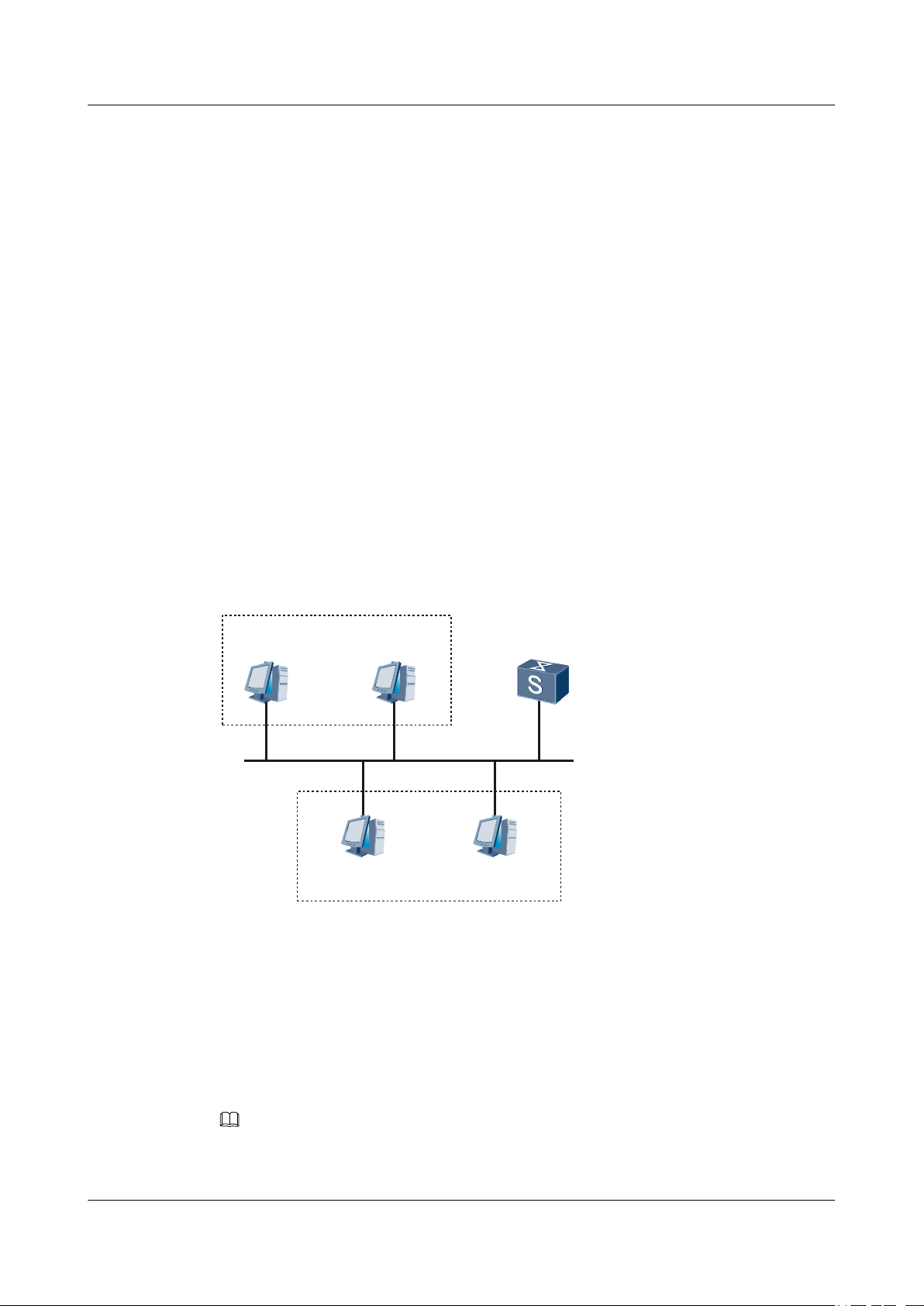
As shown in Figure 2-1, the DHCP client is on the network segment 20.20.20.0/24, whereas
the DHCP server is on the network segment of 10.10.10.0/24. DHCP messages need to be sent
by the S9300 enabled with DHCP relay so that the DHCP client can apply for the configuration
including an IP address from the DHCP server.
The DHCP server needs to be configured with an IP address pool of the network segment
20.20.20.0/24 and the route from the DHCP server to the network segment 20.20.20.0/24 is
reachable.
Figure 2-1 Networking diagram for configuring the DHCP relay agent
2-8 Huawei Proprietary and Confidential
Issue 02 (2009-08-06)
Copyright © Huawei Technologies Co., Ltd.
Page 35

Quidway S9300 Terabit Routing Switch
Configuration Guide - IP Service 2 DHCP Configuration
Configuration Roadmap
The configuration roadmap is as follows:
1. Create a DHCP server group and add DHCP servers to the DHCP server group.
2. Enable DHCP relay on the VLANIF interface.
3. Bind a VLANIF interface to a specified DHCP server group.
Data Preparation
To complete the configuration, you need the following data:
l Name of the DHCP server group
l IP address of the DHCP server in the DHCP server group
l Number and IP address of the interface enabled with DHCP relay
Procedure
Step 1 Create a DHCP server group and add DHCP servers to the DHCP server group.
# Create a DHCP server group.
<Quidway> system-view
[Quidway] dhcp server group dhcpgroup1
# Add DHCP servers to the DHCP server group.
[Quidway-dhcp-server-group-dhcpgroup1] dhcp-server 100.10.10.1
[Quidway-dhcp-server-group-dhcpgroup1] dhcp-server 100.10.10.2
[Quidway-dhcp-server-group-dhcpgroup1] quit
Step 2 Enable DHCP relay on the VLANIF interface.
# Create a VLAN and add GE 1/0/0 to the VLAN.
[Quidway] vlan 100
[Quidway-Vlan100] quit
[Quidway] interface gigabitethernet 1/0/0
[Quidway-GigabitEthernet1/0/0] port link-type access
[Quidway-GigabitEthernet1/0/0] port default vlan 100
[Quidway-GigabitEthernet1/0/0] quit
# Enable DHCP Relay on the VLANIF 100 interface.
[Quidway-Vlanif100] dhcp select relay
[Quidway-Vlanif100] quit
Step 3 Bind a VLANIF interface to a specified DHCP server group.
# Assign an IP address to the VLANIF interface.
[Quidway] interface vlanif 100
[Quidway-Vlanif100] ip address 20.20.20.1 24
# Bind the VLANIF interface to a specified DHCP server group.
[Quidway-Vlanif100] dhcp relay server-select dhcpgroup1
Step 4 On the S9300, configure a static route destined for 100.10.10.0 to ensure a reachable route
between the S9300 and 100.10.10.0.
Issue 02 (2009-08-06) Huawei Proprietary and Confidential
Copyright © Huawei Technologies Co., Ltd.
2-9
Page 36

2 DHCP Configuration
[Quidway] ip route-static 100.10.10.0 24
Step 5 Verify the configuration.
Run the display dhcp relay command on the S9300. You can view the configuration of DHCP
relay enabled on the interface.
[Quidway] display dhcp relay interface vlanif 100
** Vlanif100 DHCP Relay Configuration **
DHCP server group name : dhcpgroup1
DHCP server IP [0 ] : 100.10.10.1
DHCP server IP [1 ] : 100.10.10.2
----End
Configuration Files
Configuration file of the S9300
#
sysname Quidway
#
vlan 100
#
dhcp server group dhcpgroup1
dhcp-server 100.10.10.1
dhcp-server 100.10.10.2
#
interface Vlanif100
ip address 20.20.20.1 255.255.255.0
dhcp select relay
dhcp relay server-select dhcpgroup1
#
interface GigabitEthernet1/0/0
port link-type access
port default vlan 100
#
return
Quidway S9300 Terabit Routing Switch
Configuration Guide - IP Service
2.6.2 Example for Configuring the DHCP Relay in a Super VLAN
Networking Requirements
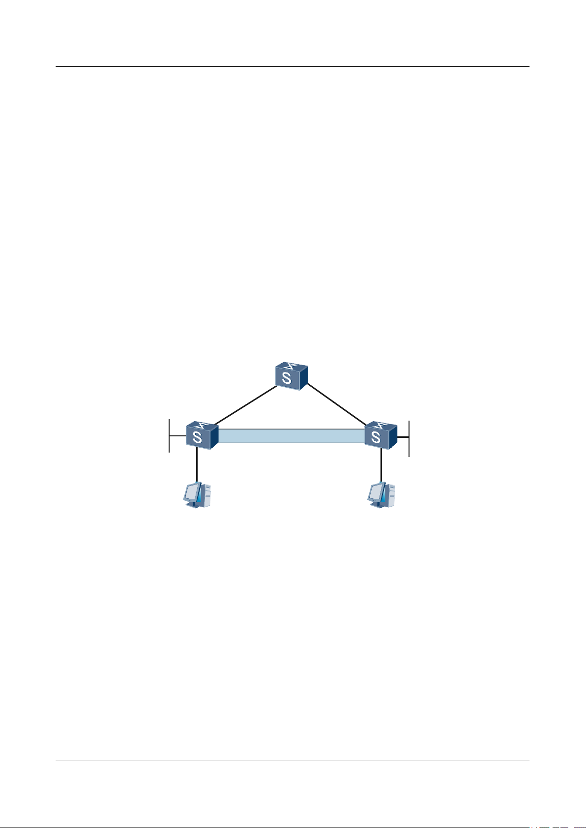
As shown in Figure 2-2, the DHCP client is on the network segment 20.20.20.0/24 and the
DHCP server is on the network segment 100.10.10.0/24. Therefore, the DHCP packet needs to
be relayed through the S9300 enabled with the DHCP relay function in the super VLAN. In this
manner, the DHCP client can apply for an IP address from the DHCP server.
An IP address pool containing the network segment 20.20.20.0/24 is configured on the DHCP
server. The DHCP server has a reachable route to 20.20.20.0/24.
2-10 Huawei Proprietary and Confidential
Copyright © Huawei Technologies Co., Ltd.
Issue 02 (2009-08-06)
Page 37

DHCP Server A
100.10.10.1/24
DHCP Server B
100.10.10.2/24
Internet
Super Vlan
VLANIF100
20.20.20.1/24
GE1/0/0
DHCP Relay
VLAN 101
sub-Vlan
VLAN 102
sub-Vlan
GE1/0/1
Quidway S9300 Terabit Routing Switch
Configuration Guide - IP Service 2 DHCP Configuration
Figure 2-2 Networking diagram for configuring the DHCP relay in a super VLAN
Configuration Roadmap
Data Preparation
Procedure
The configuration roadmap is as follows:
1. Create a DHCP server group and add DHCP servers to the group.
2. Configure VLAN 100 as the super VLAN.
3. Configure VLAN 101 and VLAN 102 as sub VLANs.
4. Enable the DHCP relay function on the VLANIF interface.
5. Bind the VLANIF interface to the specified DHCP server group.
To complete the configuration, you need the following data:
l Name of the DHCP server group
l IP addresses of the DHCP servers
l Number of IP address of the interface enabled with the DHCP relay function
Step 1 Create a DHCP server group and add DHCP servers to the group.
# Create a DHCP server group.
<Quidway> system-view
[Quidway] dhcp server group dhcpgroup1
# Add DHCP servers to the DHCP server group.
Issue 02 (2009-08-06) Huawei Proprietary and Confidential
Copyright © Huawei Technologies Co., Ltd.
2-11
Page 38

2 DHCP Configuration
Step 2 Configure the super VLAN.
Step 3 Configure sub VLANs.
Quidway S9300 Terabit Routing Switch
Configuration Guide - IP Service
[Quidway-dhcp-server-group-dhcpgroup1] dhcp-server 100.10.10.1
[Quidway-dhcp-server-group-dhcpgroup1] dhcp-server 100.10.10.2
[Quidway-dhcp-server-group-dhcpgroup1] quit
# Create VLAN 100 and configure VLAN 100 as the super VLAN.
[Quidway] vlan 100
[Quidway-Vlan100] quit
[Quidway-Vlan100] aggregate-vlan
[Quidway-Vlan100] quit
# Configure VLAN 101 as a sub VLAN and add GE 1/0/0 to VLAN 101.
[Quidway] interface gigabitethernet 1/0/0
[Quidway-Gigabitethernet1/0/0] port link-type access
[Quidway-Gigabitethernet1/0/0] quit
[Quidway] vlan 101
[Quidway-Vlan101] port gigabitethernet 1/0/0
[Quidway-Vlan101] quit
# Configure VLAN 102 as a sub VLAN and add GE 1/0/1 to VLAN 102.
Quidway] interface gigabitethernet 1/0/1
[Quidway-Gigabitethernet1/0/1] port link-type access
[Quidway-Gigabitethernet1/0/1] quit
[Quidway] vlan 102
[Quidway-Vlan102] port gigabitethernet 1/0/1
[Quidway-Vlan102] quit
# Add VLAN 101 and VLAN 102 to the super VLAN.
[Quidway] vlan 100
[Quidway-Vlan100] access-vlan 101 to 102
Step 4 Enable the DHCP relay function on VLANIF 100.
[Quidway] interface vlanif 100
[Quidway-Vlanif100] dhcp select relay
[Quidway-Vlanif100] quit
Step 5 Bind the VLANIF interface to the specified DHCP server group.
# Set the IP address for VLANIF 100.
[Quidway] interface vlanif 100
[Quidway-Vlanif100] ip address 20.20.20.1 24
# Specify a DHCP server group for the VLANIF interface.
[Quidway-Vlanif100] dhcp relay server-select dhcpgroup1
Step 6 Verify the configuration.
Run the display dhcp relay command on the S9300 to view the DHCP relay configuration on
the interface.
[Quidway] display dhcp relay interface vlanif 100
** Vlanif100 DHCP Relay Configuration **
DHCP server group name : dhcpgroup1
DHCP server IP [0 ] : 100.10.10.1
DHCP server IP [1 ] : 100.10.10.2
----End
2-12 Huawei Proprietary and Confidential
Copyright © Huawei Technologies Co., Ltd.
Issue 02 (2009-08-06)
Page 39

Quidway S9300 Terabit Routing Switch
Configuration Guide - IP Service 2 DHCP Configuration
Configuration Files
Configuration file of the S9300
#
sysname Quidway
#
vlan batch 100 101 102
#
vlan 100
aggregate-vlan
access-vlan 101 to 102
#
dhcp server group dhcpgroup1
dhcp-server 100.10.10.1
dhcp-server 100.10.10.2
#
interface Vlanif100
ip address 20.20.20.1 255.255.255.0
dhcp select relay
dhcp relay server-select dhcpgroup1
#
interface GigabitEthernet1/0/0
port link-type access
port default vlan 101
#
interface GigabitEthernet1/0/1
port link-type access
port defaulet vlan 102
#
return
Issue 02 (2009-08-06) Huawei Proprietary and Confidential
Copyright © Huawei Technologies Co., Ltd.
2-13
Page 40

Page 41

Quidway S9300 Terabit Routing Switch
Configuration Guide - IP Service 3 IP Performance Configuration
3 IP Performance Configuration
About This Chapter
This chapter describes the basic concepts of IP performance, and provides configuration
procedures and examples of IP performance.
3.1 IP Performance Supported by the S9300
This section describes the IP Performance features supported by the S9300.
3.2 Optimizing IP Performance
This section describes how to optimize IP performance of a certain network by setting IP
performance parameters.
3.3 Maintaining IP Performance
This section describes how to maintain IP performance.
3.4 Configuration Examples
This section provides several configuration examples of IP performance.
Issue 02 (2009-08-06) Huawei Proprietary and Confidential
Copyright © Huawei Technologies Co., Ltd.
3-1
Page 42

Quidway S9300 Terabit Routing Switch
3 IP Performance Configuration
3.1 IP Performance Supported by the S9300
This section describes the IP Performance features supported by the S9300.
The S9300 supports the following IP performance parameters that can be changed:
l Sending of Internet Control Message Protocol (ICMP) host unreachable packets
l Sending of ICMP redirection packets
l Sending ICMP Port Unreachable packets
l Discarding the ICMP packets whose TTL values are 1
l Discarding the ICMP packets that carry options
l Discarding ICMP Destination Unreachable packets
l Load balancing mode of IP packet forwarding
NOTE
The S9300 supports the load balancing of only the packets sent by the CPU.
l Timeout interval of the TCP FIN-Wait timer
Configuration Guide - IP Service
l Timeout interval of the TCP SYN-Wait timer
l Size of the packet receive or transmit buffer of the connection-oriented socket
l Forcible fragmentation of packets on an interface at the outbound direction
l Statistics on Transmission Control Protocol (TCP), IP, User Datagram Protocol (UDP),
and socket monitor traffic
3.2 Optimizing IP Performance
This section describes how to optimize IP performance of a certain network by setting IP
performance parameters.
3.2.1 Establishing the Configuration Task
3.2.2 Enabling an Interface to Check the Source IP Addresses of Packets
3.2.3 Configuring Forcible Fragmentation of Outgoing Packets on an Interface
3.2.4 Setting ICMP Parameters
3.2.5 Setting TCP Parameters
3.2.6 Setting the Load Balancing Mode of IP Packet Forwarding
3.2.7 Checking the Configuration
3.2.1 Establishing the Configuration Task
Applicable Environment
On certain networks, you need to change IP performance parameters to optimize the
performance. To optimize the performance, you need to set parameters.
3-2 Huawei Proprietary and Confidential
Copyright © Huawei Technologies Co., Ltd.
Issue 02 (2009-08-06)
Page 43

Quidway S9300 Terabit Routing Switch
Configuration Guide - IP Service 3 IP Performance Configuration
Pre-configuration Tasks
Before optimizing IP performance, complete the following tasks:
l Connecting interfaces and setting physical parameters of the interfaces to ensure that the
physical layer of the interfaces is in the Up state
l Setting parameters of the link layer protocol for the interfaces to ensure that the status of
the link layer protocol on the interfaces is Up
l Assigning IP addresses to interfaces
l Configuring access control lists (ACLs)
Data Preparation
To optimize IP performance, you need the following data.
No. Data
1 Number of the interface on which the Don't Fragment (DF) field of packets needs to
be deleted
2 Number of the interface on which ICMP redirection and ICMP host unreachable need
to be configured
3 Timeout interval of the TCP SYN-Wait timer, timeout interval of the TCP FIN-Wait
timer, receive or transmit buffer of the socket
3.2.2 Enabling an Interface to Check the Source IP Addresses of Packets
Context
Do as follows on the S9300.
Procedure
Step 1 Run:
system-view
The system view is displayed.
Step 2 Run:
vlan vlan-id
A VLAN is created.
Step 3 Run:
interface vlanif vlan-id
The VLANIF interface view is displayed.
Step 4 Run:
ip verify source-address
Issue 02 (2009-08-06) Huawei Proprietary and Confidential
Copyright © Huawei Technologies Co., Ltd.
3-3
Page 44

Quidway S9300 Terabit Routing Switch
3 IP Performance Configuration
The interface is enabled to check the source IP addresses.
The S9300 only checks the source IP addresses of the packets sent from the interface to the CPU.
----End
Configuration Guide - IP Service
3.2.3 Configuring Forcible Fragmentation of Outgoing Packets on an Interface
Context
Do as follows on the S9300.
Procedure
Step 1 Run:
system-view
The system view is displayed.
Step 2 Run:
vlan vlan-id
A VLAN is created.
Step 3 Run:
interface vlanif vlan-id
The VLANIF interface view is displayed.
NOTE
The DF field is deleted from the packet sent from an interface; therefore, you need to configure this function
on an outgoing interface.
Step 4 Run:
clear ip df
The interface is configured to delete the DF field.
By default, outgoing packets are not fragmented forcibly on an interface.
----End
3.2.4 Setting ICMP Parameters
Context
By default, the S9300 is enabled to send ICMP redirection packets and ICMP host unreachable
packets.
3-4 Huawei Proprietary and Confidential
Copyright © Huawei Technologies Co., Ltd.
Issue 02 (2009-08-06)
Page 45

Quidway S9300 Terabit Routing Switch
Configuration Guide - IP Service 3 IP Performance Configuration
CAUTION
l If the S9300 is disabled from sending ICMP redirection packets, the S9300 does not send
ICMP redirection packets in any case.
l If the S9300 is disabled from sending ICMP host unreachable packets, the S9300 does not
send ICMP host unreachable packets in any case.
Do as follows on the S9300.
Procedure
Step 1 Run:
system-view
The system view is displayed.
Step 2 Run:
icmp ttl-exceeded drop { slot slot-id | all }
The LPU is configured to discard the ICMP packets whose TTL values are 1.
Step 3 Run:
icmp with-options drop { slot slot-id | all }
The LPU is configured to discard the ICMP packets that carry options.
Step 4 Run:
icmp unreachable drop
The S9300 is configured to discard the ICMP Destination Unreachable packets.
Step 5 Run:
icmp port-unreachable send
The S9300 is configured to send ICMP Port Unreachable packets.
Step 6 Run:
icmp host-unreachable send
The S9300 is configured to send ICMP Host Unreachable packets.
The relation between the icmp host-unreachable send (system view) and the icmp host-unreachable send
(interface view) commands are as follows:
l When the S9300 is disabled from sending ICMP Host Unreachable packets, all the interfaces of the
l When the S9300 is enabled to send ICMP Host Unreachable packets, all the interfaces of the S9300 can
NOTE
S9300 do not send the ICMP Host Unreachable packets even if you run the icmp host-unreachable send
(interface view) command in the interface view.
send ICMP Host Unreachable packets, which conforms to the default setting. In this case, you can run the
undo icmp host-unreachable send (interface view) command to disable a specified interface from sending
the ICMP Host Unreachable packets.
Step 7 Run:
interface interface-type interface-number
The VLANIF interface view is displayed.
Issue 02 (2009-08-06) Huawei Proprietary and Confidential
Copyright © Huawei Technologies Co., Ltd.
3-5
Page 46

3 IP Performance Configuration
Step 8 Run:
icmp redirect send
The interface is enabled to send ICMP redirection packets.
Step 9 Run:
icmp host-unreachable send
The interface is enabled to send ICMP host unreachable packets.
----End
3.2.5 Setting TCP Parameters
Context
You can set the following TCP parameters:
l SYN-Wait timer: When sending packets with the SYN flag, TCP starts the SYN-Wait timer.
If no response is received before the SYN-Wait timer expires, the TCP connection ends.
The timeout interval of the TCP SYN-Wait timer is an integer that ranges from 2 to 600,
in seconds. By default, the value is 75s.
l FIN-Wait timer: When the TCP connection status changes from FIN_WAIT_1 to
FIN_WAIT_2, the FIN-Wait timer is enabled. If no packet with the FIN flag is received
before the FIN-Wait timer expires, the TCP connection ends. The timeout interval of the
TCP FIN-Wait timer is an integer that ranges from 76 to 3600, in seconds. By default, the
value is 675s.
l Size of the packet receive or transmit buffer: The value is an integer that ranges from 1 to
32, in Kbytes. By default, the value is 8 Kbytes.
Quidway S9300 Terabit Routing Switch
Configuration Guide - IP Service
Procedure
Step 1 Run:
Step 2 Run:
Step 3 Run:
Step 4 Run:
If you run the tcp window command repeatedly in the same system view, the latest configuration
overrides the previous configuration.
Do as follows on the S9300.
system-view
The system view is displayed.
tcp timer syn-timeout interval
The timeout interval of the TCP SYN-Wait timer is set.
tcp timer fin-timeout interval
The timeout interval of the TCP FIN-Wait timer (FIN_WAIT_2) is set.
tcp window window-size
The size of the packet receive or transmit buffer is set.
----End
3-6 Huawei Proprietary and Confidential
Copyright © Huawei Technologies Co., Ltd.
Issue 02 (2009-08-06)
Page 47

Quidway S9300 Terabit Routing Switch
Configuration Guide - IP Service 3 IP Performance Configuration
3.2.6 Setting the Load Balancing Mode of IP Packet Forwarding
Context
When flow-based load balancing mode is adopted, the S9300 performs the Hash algorithm based
on the protocol type, source IP address and mask, destination IP address and mask, source port
number, and destination port number, and then selects a route for forwarding packets according
to the Hash value.
When packet-based load balancing mode is adopted, the S9300 selects different links for
forwarding packets.
By default, the flow-based load balancing mode is adopted.
The load-balance command is valid for forwarding of Multiprotocol Label Switching Protocol
(MPLS) packets. For details on this command, see "MPLS Public Configuration" in the Quidway
S9300 Terabit Routing Switch Configuration Guide - MPLS.
Do as follows on the S9300.
Procedure
Step 1 Run:
system-view
The system view is displayed.
Step 2 Run:
load-balance { flow | packet } [ all | slot slot-id ]
The load balancing mode is configured for IP packet forwarding.
NOTE
The value of slot-id can only be 0. That is, theS9300 performs load balancing only for the packets sent out
from the CPU of the main control board.
----End
3.2.7 Checking the Configuration
Prerequisite
The configurations of optimizing IP performance are complete.
Procedure
l Run the display tcp status [ [ task-id task-id ] [ socket-id socket-id ] | [ local-ip ipv4-
address ] [ local-port local-port-number ] [ remote-ip ipv4-address ] [ remote-port
remote-port-number ] ] command to check the TCP connection status.
l Run the display tcp statistics command to check the statistics on TCP traffic.
l Run the display udp statistics command to check the statistics on UDP traffic.
l Run the display ip statistics command to check the statistics on IP traffic.
l Run the display ip socket [ monitor ] [ task-id task-id socket-id socket-id | sock-type
socket-type ] command to check information about the created IPv4 socket.
Issue 02 (2009-08-06) Huawei Proprietary and Confidential
Copyright © Huawei Technologies Co., Ltd.
3-7
Page 48

3 IP Performance Configuration
l Run the display icmp statistics command to check the statistics on ICMP traffic.
l Run the display rawlink statistics command to check the Rawlink statistics.
l Run the display fib [ slot-id ] command to check the Forwarding Information Base (FIB)
table on the Line Processing Unit (LPU).
l Run the display fib [ slot-id ] [ vpn-instance vpn-instance-name ] [ verbose ] [ | { begin
| exclude | include } regular-expression ] command to check information about the FIB
table.
l Run the display fib [ vpn-instance vpn-instance-name ] acl acl-number [ verbose ]
command to check information about the FIB entries that match ACL rules in a certain
format.
l Run the display fib [ vpn-instance vpn-instance-name ] interface interface-type interface-
number command to check information about the FIB entries with the outgoing interface
as a specified interface.
l Run the display fib [ vpn-instance vpn-instance-name ] ip-prefix prefix-name
[ verbose ] command to check information about the FIB entries that match a specified IP
prefix list.
l Run the display fib [ slot-id ] [ vpn-instance vpn-instance-name ] destination-address1
[ destination-mask1 ] [ longer ] [ verbose ] command to check information about the FIB
entries that match destination IP addresses in a specified range.
Quidway S9300 Terabit Routing Switch
Configuration Guide - IP Service
l Run the display fib [ vpn-instance vpn-instance-name ] next-hop ip-address command
to check information about the FIB entries that match the specified next hop address.
l Run the display fib [ slot-id ] [ vpn-instance vpn-instance-name ] statistics command to
check the total number of FIB entries.
----End
3.3 Maintaining IP Performance
This section describes how to maintain IP performance.
3.3.1 Clearing IP Performance Statistics
3.3.2 Monitoring the Running Status of IP Performance
3.3.3 Debugging IP Performance
3.3.1 Clearing IP Performance Statistics
Context
CAUTION
The statistics on IP, TCP, or UDP traffic cannot be restored after you clear them. So, confirm
the action before you use the command.
3-8 Huawei Proprietary and Confidential
Copyright © Huawei Technologies Co., Ltd.
Issue 02 (2009-08-06)
Page 49

Quidway S9300 Terabit Routing Switch
Configuration Guide - IP Service 3 IP Performance Configuration
Procedure
l Run the reset ip statistics [ interface interface-type interface-number ] command in the
user view to clear the statistics on IP traffic.
l Run the reset ip socket monitor[ task-id task-id socket-id socket-id ] command in the
user view to clear the information about the socket monitor.
l Run the reset tcp statistics command in the user view to clear the statistics on TCP traffic.
l Run the reset udp statistics command in the user view to clear the statistics on UDP traffic.
l Run the reset rawlink statistics command in the user view to clear the Rawlink statistics.
----End
3.3.2 Monitoring the Running Status of IP Performance
Context
In routine maintenance, you can run the following command in any view to view the running
status of IP performance.
Procedure
l Run the display tcp status [ [ task-id task-id ] [ socket-id socket-id ] | [ local-ip ipv4-
address ] [ local-port local-port-number ] [ remote-ip ipv4-address ] [ remote-port
remote-port-number ] ] command to check the TCP connection status.
l Run the display tcp statistics command to check the statistics on TCP traffic.
l Run the display udp statistics command to check the statistics on UDP traffic.
l Run the display ip statistics command to check the statistics on IP traffic.
l Run the display ip socket [ monitor ] [ task-id task-id socket-id socket-id | sock-type
socket-type ] command to check information about the created IPv4 socket.
l Run the display icmp statistics command to check the statistics on ICMP traffic.
l Run the display rawlink statistics command to check the Rawlink statistics.
l Run the display fib [ slot-id ] command to check the FIB table on the LPU.
l Run the display fib [ slot-id ] [ vpn-instance vpn-instance-name ] [ verbose ] [ | { begin
| exclude | include } regular-expression ] command to check information about the FIB
table.
l Run the display fib [ vpn-instance vpn-instance-name ] acl acl-number [ verbose ]
command to check information about the FIB entries that match ACL rules in a certain
format.
l Run the display fib [ vpn-instance vpn-instance-name ] interface interface-type interface-
number command to check information about the FIB entries with the outgoing interface
as a specified interface.
l Run the display fib [ vpn-instance vpn-instance-name ] ip-prefix prefix-name
[ verbose ] command to check information about the FIB entries that match a specified IP
prefix list.
l Run the display fib [ slot-id ] [ vpn-instance vpn-instance-name ] destination-address1
[ destination-mask1 ] [ longer ] [ verbose ] command to check information about the FIB
entries that match destination IP addresses in a specified range.
Issue 02 (2009-08-06) Huawei Proprietary and Confidential
Copyright © Huawei Technologies Co., Ltd.
3-9
Page 50

3 IP Performance Configuration
l Run the display fib [ vpn-instance vpn-instance-name ] next-hop ip-address command
to check information about the FIB entries that match the specified next hop address.
l Run the display fib [ slot-id ] [ vpn-instance vpn-instance-name ] statistics command to
check the total number of FIB entries.
----End
3.3.3 Debugging IP Performance
Context
CAUTION
Debugging affects the performance of the system. So, after debugging, run the undo debugging
all command to disable it immediately.
When an IP, TCP, UDP, RAWIP, or RAWLINK fault occurs, run the following debugging
commands in the user view to locate the fault.
Quidway S9300 Terabit Routing Switch
Configuration Guide - IP Service
Procedure
For the procedure for displaying the debugging information, see "Information Center" in the
Quidway S9300 Terabit Routing SwitchConfiguration Guide - Device Management. For details
on debugging commands, see the Quidway S9300 Terabit Routing Switch Debugging
Reference.
l Run the debugging ip packet [ error ] [ acl acl-number ] [ verbose ] command in the user
view to debug IP packets.
l Run the debugging ip icmp [ verbose ] command in the user view to debug ICMP packets.
l Run the debugging udp packet [ src-ip src-address ] [ src-port src-port ] [ dest-ip dest-
address ] [ dest-port dest-port ] or debugging udp packet [ task-id task-id ] [ socket-id
socket-id ] command in the user view to debug UDP packets.
l Run the debugging tcp packet [ src-ip src-address ] [ src-port src-port ] [ dest-ip dest-
address ] [ dest-port dest-port ] [ flag flag-number ] or debugging tcp packet [ task-id
task-id ] [ socket-id socket-id ] [ flag flag-number ] command in the user view to debug
UDP packets.
l Run the debugging tcp event [ local-ip local-address ] [ local-port local-port ] [ remote-
ip remote-address ] [ remote-port remote-port ] or debugging tcp event [ task-id task-
id ] [ socket-id socket-id ] command in the user view to debug TCP events.
l Run the debugging tcp md5 [ src-ip src-address ] [ src-port src-port ] [ dest-ip dest-
address ] [ dest-port dest-port ] or debugging tcp md5 [ task-id task-id ] [ socket-id
socket-id ] command in the user view to debug TCP Message Digest Algorithm 5 (MD5)
authentication.
l Run the debugging rawip packet [ src-ip src-address ] [ dest-ip dest-address ]
[ protocol protocol-number ] [ verbose verbose-number ] or debugging rawip packet
[ task-id task-id ] [ socket-id socket-id ] [ verbose verbose-number ] command in the user
view to debug RAWIP packets.
l Run the debugging rawlink packet [ src-mac src-mac ] [ dest-mac dest-mac ]
[ verbose verbose-number ] or debugging rawlink packet [ task-id task-id ] [ socket-id
3-10 Huawei Proprietary and Confidential
Copyright © Huawei Technologies Co., Ltd.
Issue 02 (2009-08-06)
Page 51

Internet
S9300A
S9300BS9300C
GE1/0/0
VLANIF10
1.1.1.1/24
VLANIF10
1.1.1.2/24
GE1/0/0GE1/0/0
VLANIF10
2.2.2.2/24
Quidway S9300 Terabit Routing Switch
Configuration Guide - IP Service 3 IP Performance Configuration
socket-id ] [ verbose verbose-number ] command in the user view to debug RAWLINK
packets.
----End
3.4 Configuration Examples
This section provides several configuration examples of IP performance.
3.4.1 Example for Disabling the Sending of ICMP Redirection Packets
3.4.2 Example for Configuring ICMP Host Unreachable Packets
3.4.3 Example for Optimizing System Performance by Discarding Certain ICMP Packets
3.4.1 Example for Disabling the Sending of ICMP Redirection
Packets
Networking Requirements
As shown in Figure 3-1, to limit the sending of ICMP redirection packets, S9300-A, S9300-B,
and S9300-C are required and these devices are connected through their GE interfaces.
Figure 3-1 Networking diagram for disabling the sending of ICMP redirection packets
Configuration Roadmap
Issue 02 (2009-08-06) Huawei Proprietary and Confidential
The configuration roadmap is as follows:
1. Assign IP addresses to interfaces on routing devices.
2. Configure static routes to indirectly connected devices.
Copyright © Huawei Technologies Co., Ltd.
3-11
Page 52

3 IP Performance Configuration
3. Disable the sending of ICMP redirection packets on an interface.
Data Preparation
To complete the configuration, you need the following data:
l Static routes to indirectly connected devices
l IP address of the interface
Procedure
Step 1 Assign IP addresses to VLANIF interfaces.
# Configure S9300-A.
<Quidway> system-view
[Quidway] sysname S9300-A
[S9300-A] vlan 10
[S9300-A-Vlan10] quit
[S9300-A] interface gigabitethernet 1/0/0
[S9300-A-GigabitEthernet1/0/0] port hybrid tagged vlan 10
[S9300-A-GigabitEthernet1/0/0] quit
[S9300-A] interface vlanif 10
[S9300-A-Vlanif10] ip address 1.1.1.1 24
[S9300-A-Vlanif10] quit
Quidway S9300 Terabit Routing Switch
Configuration Guide - IP Service
# Configure S9300-B.
<Quidway> system-view
[Quidway] sysname S9300-B
[S9300-B] vlan 10
[S9300-B-Vlan10] quit
[S9300-B] interface gigabitethernet 1/0/0
[S9300-B-GigabitEthernet1/0/0] port hybrid tagged vlan 10
[S9300-B-GigabitEthernet1/0/0] quit
[S9300-B] interface vlanif 10
[S9300-B-Vlanif10] ip address 1.1.1.2 24
[S9300-B-Vlanif10] quit
# Configure S9300-C.
<Quidway> system-view
[Quidway] sysname S9300-C
[S9300-C] vlan 10
[S9300-C-Vlan10] quit
[S9300-C] interface gigabitethernet 1/0/0
[S9300-C-GigabitEthernet1/0/0] port hybrid tagged vlan 10
[S9300-C-GigabitEthernet1/0/0] quit
[S9300-C] interface vlanif 10
[S9300-C-Vlanif10] ip address 2.2.2.2 24
[S9300-C-Vlanif10] quit
Step 2 Configure static routes.
# Configure S9300-A.
[S9300-A] ip route-static 2.2.2.0 255.255.255.0 1.1.1.2
# Configure S9300-B.
[S9300-B] ip route-static 2.2.2.0 255.255.255.0 1.1.1.1
Step 3 Disable the sending of ICMP redirection packets on VLANIF 10 of S9300-B.
[S9300-B] interface vlanif 10
[S9300-B-Vlanif10] undo icmp redirect send
3-12 Huawei Proprietary and Confidential
Copyright © Huawei Technologies Co., Ltd.
Issue 02 (2009-08-06)
Page 53

Quidway S9300 Terabit Routing Switch
Configuration Guide - IP Service 3 IP Performance Configuration
[S9300-B-Vlanif10] quit
Step 4 Verify the configuration.
# Debug ICMP packets on S9300-B.
<S9300-B> debugging ip icmp
# Run the ping command on S9300-A. You can view that S9300-B does not send host redirection
packets.
[S9300-A] ping 2.2.2.2
PING 2.2.2.2: 56 data bytes, press CTRL_C to break
Reply from 2.2.2.2: bytes=56 Sequence=1 ttl=255 time=3 ms
Reply from 2.2.2.2: bytes=56 Sequence=2 ttl=255 time=3 ms
Reply from 2.2.2.2: bytes=56 Sequence=3 ttl=255 time=3 ms
Reply from 2.2.2.2: bytes=56 Sequence=4 ttl=255 time=3 ms
Reply from 2.2.2.2: bytes=56 Sequence=5 ttl=255 time=3 ms
--- 2.2.2.2 ping statistics -- 5 packet(s) transmitted
5 packet(s) received
0.00% packet loss
round-trip min/avg/max = 3/3/3 ms
----End
Configuration Files
l Configuration file of S9300-A
#
sysname S9300-A
#
vlan batch 10
#
interface vlanif 10
ip address 1.1.1.1 255.255.255.0
#
interface GigabitEthernet1/0/0
port hybrid tagged vlan 10
#
ip route-static 2.2.2.0 255.255.255.0 1.1.1.2
#
return
l Configuration file of S9300-B
#
sysname S9300-B
#
vlan batch 10
#
interface vlanif 10
ip address 1.1.1.2 255.255.255.0
undo icmp redirect send
#
interface GigabitEthernet1/0/0
port hybrid tagged vlan 10
#
ip route-static 2.2.2.0 255.255.255.0 1.1.1.1
#
return
l Configuration file of S9300-C
#
sysname S9300-C
#
interface vlanif 10
ip address 2.2.2.2 255.255.255.0
Issue 02 (2009-08-06) Huawei Proprietary and Confidential
Copyright © Huawei Technologies Co., Ltd.
3-13
Page 54

S9300A
S9300C
GE1/0/0
VLANIF10
1.1.1.1/24
GE1/0/1
VLANIF11
2.2.2.2/24
S9300B
GE1/0/0
VLANIF10
1.1.1.2/24
GE1/0/1
VLANIF11
2.2.2.1/24
Quidway S9300 Terabit Routing Switch
3 IP Performance Configuration
#
interface GigabitEthernet1/0/0
port hybrid tagged vlan 10
#
return
Configuration Guide - IP Service
3.4.2 Example for Configuring ICMP Host Unreachable Packets
Networking Requirements
As shown in Figure 3-2, to limit the sending of ICMP redirection packets, S9300-A, S9300-B,
and S9300-C are required and these devices are connected through their GE interfaces.
Figure 3-2 Networking diagram for disabling the sending of ICMP host unreachable packets
Configuration Roadmap
The configuration roadmap is as follows:
1. Assign IP addresses to interfaces on S9300s.
2. Configure static routes to indirectly connected devices.
3. Enable the sending of ICMP host unreachable packets in the system view.
4. Enable the sending of ICMP host unreachable packets in the interface view.
Data Preparation
To complete the configuration, you need the following data:
l Static routes to indirectly connected devices
l IP address of the interface
NOTE
By default, the sending of ICMP host unreachable packets is enabled on the system view and on the
interface view. If the configuration is not changed, you can skip this configuration.
3-14 Huawei Proprietary and Confidential
Copyright © Huawei Technologies Co., Ltd.
Issue 02 (2009-08-06)
Page 55

Quidway S9300 Terabit Routing Switch
Configuration Guide - IP Service 3 IP Performance Configuration
Procedure
Step 1 Configure S9300-A.
# Assign an IP address to VLANIF 10.
<Quidway> system-view
[Quidway] sysname S9300-A
[S9300-A] vlan 10
[S9300-A-Vlan10] quit
[S9300-A] interface gigabitethernet 1/0/0
[S9300-A-GigabitEthernet1/0/0] port hybrid tagged vlan 10
[S9300-A-GigabitEthernet1/0/0] quit
[S9300-A] interface vlanif 10
[S9300-A-Vlanif10] ip address 1.1.1.1 24
[S9300-A-Vlanif10] quit
# Configure a static route on S9300-A.
[S9300-A] ip route-static 2.2.2.0 24 1.1.1.2
Step 2 Configure S9300-B.
# Disable the sending of ICMP host unreachable packets on S9300-B and assign an IP address
to VLANIF 10.
<Quidway> system-view
[Quidway] sysname S9300-B
[S9300-B] icmp host-unreachable send
[S9300-B] vlan 10
[S9300-B-Vlan10] quit
[S9300-B] interface gigabitethernet 1/0/0
[S9300-B-GigabitEthernet1/0/0] port hybrid tagged vlan 10
[S9300-B-GigabitEthernet1/0/0] quit
[S9300-B] interface vlanif 10
[S9300-B-Vlanif10] ip address 1.1.1.2 24
[S9300-B-Vlanif10] quit
[S9300-B] vlan 11
[S9300-B-Vlan11] quit
[S9300-B] interface gigabitethernet 1/0/1
[S9300-B-GigabitEthernet1/0/1] port hybrid tagged vlan 11
[S9300-B-GigabitEthernet1/0/1] quit
[S9300-B] interface vlanif 11
[S9300-B-Vlanif11] ip address 2.2.2.1 24
[S9300-B-Vlanif11] icmp host-unreachable send
[S9300-B-Vlanif11] quit
Step 3 Configure S9300-C.
# Assign an IP address to VLANIF 11 on S9300-C.
<Quidway> system-view
[Quidway] sysname S9300-C
[S9300-C] vlan 11
[S9300-C-Vlan11] quit
[S9300-C] interface gigabitethernet 1/0/1
[S9300-C-GigabitEthernet1/0/1] port hybrid tagged vlan 11
[S9300-C-GigabitEthernet1/0/1] quit
[S9300-C] interface vlanif 11
[S9300-C-Vlanif11] ip address 2.2.2.2 24
[S9300-C-Vlanif11] quit
Step 4 Verify the configuration.
# Debug ICMP packets on S9300-A.
<S9300-A> debugging ip icmp
<S9300-A> terminal monitor
<S9300-A> terminal debugging
Issue 02 (2009-08-06) Huawei Proprietary and Confidential
Copyright © Huawei Technologies Co., Ltd.
3-15
Page 56

3 IP Performance Configuration
# Run the ping 2.2.2.3 command on S9300-A. According to the received packet captured by the
tester on S9300-A, S9300-B sends host unreachable packets.
[S9300-A] ping 2.2.2.3
----End
Configuration Files
l Configuration file of S9300-A
#
sysname S9300-A
#
vlan 10
#
interface vlanif 10
ip address 1.1.1.1 255.255.255.0
#
interface GigabitEthernet1/0/0
port hybrid tagged vlan 10
#
ip route-static 2.2.2.0 255.255.255.0 1.1.1.2
#
return
l Configuration file of S9300-B
#
sysname S9300-B
#
vlan batch 10 to 11
#
interface vlanif 10
ip address 1.1.1.2 255.255.255.0
#
interface vlanif 11
ip address 2.2.2.1 255.255.255.0
#
interface GigabitEthernet1/0/0
port hybrid tagged vlan 10
#
interface GigabitEthernet1/0/1
port hybrid tagged vlan 11
#
return
l Configuration file of S9300-C
#
sysname S9300-C
#
vlan 11
#
interface vlanif 11
ip address 2.2.2.2 255.255.255.0
#
interface GigabitEthernet1/0/1
port hybrid tagged vlan 11
#
return
Quidway S9300 Terabit Routing Switch
Configuration Guide - IP Service
3.4.3 Example for Optimizing System Performance by Discarding Certain ICMP Packets
3-16 Huawei Proprietary and Confidential
Copyright © Huawei Technologies Co., Ltd.
Issue 02 (2009-08-06)
Page 57

S9300
BRAS
DSLAM
Enterprise
user
Individual
user
Internet
User
network
Quidway S9300 Terabit Routing Switch
Configuration Guide - IP Service 3 IP Performance Configuration
Networking Requirement
As shown in Figure 3-3, the S9300 functions as the convergence device. The enterprise users,
individual users, and DSLAMs are attached to the S9300. The S9300 is connected to the Internet
through a BRAS. To reduce the workload on the S9300, you need to configure the S9300 to
discard certain ICMP packets. The ICMP packets to be discarded have any of the following
characteristics:
l The TTL values of the packets are 1.
l The packets carry options.
l The destination addresses of the packets are unreachable.
Figure 3-3 Networking for configuring ICMP security function
Configuration Roadmap
Perform the configurations in the system view of the S9300. The configuration roadmap is as
follows:
l Configure the S9300 to discard the ICMP packets whose TTL values are 1.
l Configure the S9300 to discard the ICMP packets that carry options.
l Configure the S9300 to discard the ICMP packets whose destination addresses are
unreachable.
Data Preparation
None
Issue 02 (2009-08-06) Huawei Proprietary and Confidential
Copyright © Huawei Technologies Co., Ltd.
3-17
Page 58

3 IP Performance Configuration
Procedure
Step 1 Configure the S9300 to discard certain ICMP packets.
# Configure the S9300 to discard the ICMP packets whose TTL values are 1.
<Quidway> system-view
[Quidway] icmp ttl-exceeded drop all
# Configure the S9300 to discard the ICMP packets that carry options.
[Quidway] icmp with-options drop all
# Configure the S9300 to discard the ICMP packets whose destination addresses are unreachable.
[Quidway] icmp unreachable drop
Step 2 Verify the configuration.
# Run the display this command in the system view to display the configuration of the ICMP
security function.
[Quidway] display this
#
icmp unreachable drop
icmp ttl-exceeded drop slot 1
icmp with-options drop slot 1
icmp ttl-exceeded drop slot 2
icmp with-options drop slot 2
icmp ttl-exceeded drop slot 3
icmp with-options drop slot 3
#
Quidway S9300 Terabit Routing Switch
Configuration Guide - IP Service
----End
Configuration Files
#
sysname Quidway
#
icmp unreachable drop
icmp ttl-exceeded drop slot 1
icmp with-options drop slot 1
icmp ttl-exceeded drop slot 2
icmp with-options drop slot 2
icmp ttl-exceeded drop slot 3
icmp with-options drop slot 3
#
return
3-18 Huawei Proprietary and Confidential
Copyright © Huawei Technologies Co., Ltd.
Issue 02 (2009-08-06)
Page 59

Quidway S9300 Terabit Routing Switch
Configuration Guide - IP Service 4 IP Unicast PBR Configuration
4 IP Unicast PBR Configuration
About This Chapter
This chapter describes the principle of IP unicast policy-based routing (PBR), and provides
configuration procedures and examples of IP unicast PBR.
4.1 Introduction to IP Unicast PBR
This section describes the basic concepts of IP Unicast PBR.
4.2 IP Unicast PBR Features Supported by the S9300
This section describes the IP unicast PBR features supported by the S9300.
4.3 Configuring IP Unicast PBR
This section describes how to configure IP unicast PBR so that certain packets are forwarded
through a specified outgoing interface.
4.4 Maintaining IP Unicast PBR
This section describes how to maintain IP unicast PBR.
4.5 Configuration Examples
This section provides several configuration examples of IP unicast PBR.
Issue 02 (2009-08-06) Huawei Proprietary and Confidential
Copyright © Huawei Technologies Co., Ltd.
4-1
Page 60

Quidway S9300 Terabit Routing Switch
4 IP Unicast PBR Configuration
Configuration Guide - IP Service
4.1 Introduction to IP Unicast PBR
This section describes the basic concepts of IP Unicast PBR.
PBR is a routing mechanism based on user-defined policies. Compared with the routing based
on the destination address of data packets, PBR is more flexible. It is secure and facilitates load
balancing of routes.
4.2 IP Unicast PBR Features Supported by the S9300
This section describes the IP unicast PBR features supported by the S9300.
The S9300 configured with PBR supports routing based on the source IP address and length of
the packets and can specify routes flexibly. When sending packets, the S9300 first forwards
them according to the policy-based route. If no policy-based route exists or the policy is
configured but no entry is matched, the S9300 forwards the packets according to the routing
table.
The S9300 supports only local PBR. That is, the S9300 can send packets generated locally
through the policy-based route, but does not forward the received packets through the policybased route.
NOTE
Do not be confused by the concepts of IP unicast policy-based routing and routing policy.
4.3 Configuring IP Unicast PBR
This section describes how to configure IP unicast PBR so that certain packets are forwarded
through a specified outgoing interface.
4.3.1 Establishing the Configuration Task
4.3.2 Defining Matching Rules for PBR
4.3.3 Defining Actions of PBR
4.3.4 Applying a Policy-based Route
4.3.5 Checking the Configuration
4.3.1 Establishing the Configuration Task
Applicable Environment
A private network is connected to the public network through an S9300, which provides multiple
interfaces to connect to the public network. To forward certain packets through a specified
outgoing interface, you need to configure IP unicast PBR.
Pre-configuration Tasks
Before configuring IP unicast PBR, complete the following tasks:
4-2 Huawei Proprietary and Confidential
Copyright © Huawei Technologies Co., Ltd.
Issue 02 (2009-08-06)
Page 61

Quidway S9300 Terabit Routing Switch
Configuration Guide - IP Service 4 IP Unicast PBR Configuration
l Configuring the interface connecting the S9300 and another device
l Configuring the link layer protocol on an interface
l Configuring an ACL to match packets
l Configuring a virtual private network (VPN) if the packets need to be sent to the VPN
Data Preparation
To configure IP unicast PBR, you need the following data.
No. Data
1 Name of the policy, number of the node, default action being permit or deny for
packets
2 Minimum and maximum number of bytes of packets
3 Number of an ACL matching packets
4 New priority of packets
5 Default next hop or outgoing interface of packets in a specified policy
6 Next hop or number of the outgoing interface of packets in a specified policy
7 Name of the VPN instance that the packets belong to in a specified policy
4.3.2 Defining Matching Rules for PBR
Context
When configuring PBR, pay attention to the following points:
l PBR is used to import routes and forward IP packets according to the policy-based route.
l The contents of PBR are specified by if-match and apply clauses.
l A policy can contain multiple if-match clauses. That is, if-match acl and if-match packet-
length can be used together.
– When the if-match acl acl-number command is run repeatedly, the latest configuration
overrides the previous configuration.
– When the if-match packet-length min-length max-length command is run repeatedly,
the latest configuration overrides the previous configuration.
l permit indicates that the policy-based route is used for the packets that satisfy matching
rules; deny indicates that the policy-based route is not applied to the packets that satisfy
matching rules.
l A policy name identifies a policy. A policy can contain multiple policy nodes. The policy
node is specified by node-id. The smaller the value of node-id is, the higher the preference
of the policy is.
Do as follows on the S9300.
Issue 02 (2009-08-06) Huawei Proprietary and Confidential
Copyright © Huawei Technologies Co., Ltd.
4-3
Page 62

4 IP Unicast PBR Configuration
Procedure
Step 1 Run:
system-view
The system view is displayed.
Step 2 Run:
policy-based-route policy-name { deny | permit } node node-id
A policy or a node is created.
Step 3 Run:
if-match { packet-length min-length max-length | acl acl-number }
A matching rule for IP packets is set.
----End
4.3.3 Defining Actions of PBR
Quidway S9300 Terabit Routing Switch
Configuration Guide - IP Service
Context
Procedure
Step 1 Run:
Step 2 Run:
When defining actions of PBR, pay attention to the following points:
l A policy can contain multiple apply clauses that are used together.
l If multiple next hops are set in a policy, packets are balanced among the multiple next hops.
l If the apply ip-address next-hop command is used to configure two next hops and then
the command is used to configure a next hop, the next hop configured later overrides the
first next hop configured previously. The second next hop that is configured previously,
however, is not overridden.
Do as follows on the S9300.
system-view
The system view is displayed.
policy-based-route policy-name { deny | permit }node node-id
The Policy-Based-Route view is displayed.
Step 3 (Optional) Run:
apply ip-precedence precedence
The priority of packets is set.
The apply ip-precedence command is used to set the priority of IP packets. The value of
precedence ranges from 0 to 7. You can also use preference keywords to represent its priority
values. Table 4-1 lists the relations between keywords and values.
4-4 Huawei Proprietary and Confidential
Copyright © Huawei Technologies Co., Ltd.
Issue 02 (2009-08-06)
Page 63

Quidway S9300 Terabit Routing Switch
Configuration Guide - IP Service 4 IP Unicast PBR Configuration
Table 4-1 Relations between values and keywords
Value Keyword
0 Routine
1 Priority
2 Immediate
3 Flash
4 Flash-override
5 Critical
6 Internet
7 Network
Step 4 (Optional) Run:
apply ip-address default next-hop ip-address1 [ ip-address2 ]
The default next hop of packets is set.
NOTE
l The IP address of the default next hop of packets cannot be a local IP address.
l The default next hop of packets takes effect only when a route of packets is not found in the routing
table.
Step 5 (Optional) Run:
apply ip-address next-hop ip-address1 [ ip-address2 ]
The next hop of packets is set.
NOTE
The IP address of the next hop of packets cannot be a local IP address.
----End
4.3.4 Applying a Policy-based Route
Context
A policy-based route can be only applied to the local S9300.
Do as follows on the S9300.
Procedure
l Run:
system-view
The system view is displayed.
l Run:
ip local policy-based-route policy-name
Issue 02 (2009-08-06) Huawei Proprietary and Confidential
Copyright © Huawei Technologies Co., Ltd.
4-5
Page 64

4 IP Unicast PBR Configuration
The policy-based route is applied on the local S9300.
A policy-based route takes effect for only the packets generated by the local S9300. You
can configure only one local policy-based route. If you configure multiple local policybased routes, the latest configuration overrides the previous configuration.
----End
4.3.5 Checking the Configuration
Prerequisite
The configurations of IP unicast PBR are complete.
Procedure
l Run the display ip policy-based-route command to check the policy used on the local
S9300.
l Run the display ip policy-based-route setup local command to check the the policy-based
route on the local S9300.
Quidway S9300 Terabit Routing Switch
Configuration Guide - IP Service
l Run the display ip policy-based-route statistics local command to check the statistics on
the policy-based route on the local S9300.
l Run the display policy-based-route [ policy-name ] command to check the contents of a
created policy.
----End
4.4 Maintaining IP Unicast PBR
This section describes how to maintain IP unicast PBR.
4.4.1 Monitoring the Running Status of IP Unicast PBR
4.4.2 Debugging IP Unicast PBR
4.4.1 Monitoring the Running Status of IP Unicast PBR
Context
In routine maintenance, you can run the following command in any view to view the running
status of IP unicast PBR.
Procedure
l Run the display ip policy-based-route command to check the policy used on the local
S9300.
l Run the display ip policy-based-route setup local command to check the policy-based
route on the local S9300.
l Run the display ip policy-based-route statistics local command to check the statistics on
the policy-based route on the local S9300.
4-6 Huawei Proprietary and Confidential
Copyright © Huawei Technologies Co., Ltd.
Issue 02 (2009-08-06)
Page 65

Quidway S9300 Terabit Routing Switch
Configuration Guide - IP Service 4 IP Unicast PBR Configuration
l Run the display policy-based-route [ policy-name ] command to check the contents of a
created policy.
----End
4.4.2 Debugging IP Unicast PBR
Context
CAUTION
Debugging affects the performance of the system. So, after debugging, run the undo debugging
all command to disable it immediately.
When an IP unicast PBR fault occurs, you can run the debugging command in the user view to
locate the fault.
For the procedure for displaying the debugging information, see "Information Center" in the
Quidway S9300 Terabit Routing SwitchConfiguration Guide - Device Management. For details
on debugging commands, see the Quidway S9300 Terabit Routing Switch Debugging
Reference.
Procedure
Step 1 Run the debugging ip policy-based-route command in the user view to debug the policy-based
route.
----End
4.5 Configuration Examples
This section provides several configuration examples of IP unicast PBR.
4.5.1 Example for Configuring PBR Based on the Protocol Type
4.5.2 Example for Configuring PBR Based on the Packet Length
4.5.1 Example for Configuring PBR Based on the Protocol Type
Networking Requirements
As shown in Figure 4-1, a policy-based route named aaa is defined. All TCP packets sent from
S9300A are sent through VLANIF 11, whereas other packets are still forwarded according to
the routing table. S9300A is directly connected to S9300B and S9300C. The route between
S9300B and S9300C is unreachable.
Issue 02 (2009-08-06) Huawei Proprietary and Confidential
Copyright © Huawei Technologies Co., Ltd.
4-7
Page 66

Internet
S9300 A
S9300 B
S9300 C
GE1/0/0
VLANIF11
1.1.2.1/24
GE2/0/0
VLANIF12
1.1.3.1/24
GE1/0/0
VLANIF11
1.1.2.2/24
GE2/0/0
VLANIF12
1.1.3.2/24
4 IP Unicast PBR Configuration
Figure 4-1 Networking diagram for configuring PBR based on the protocol type
Configuration Roadmap
The configuration roadmap is as follows:
1. Define an ACL.
2. Define matching rules and actions for PBR.
3. Enable local PBR.
Quidway S9300 Terabit Routing Switch
Configuration Guide - IP Service
Data Preparation
To complete the configuration, you need the following data:
l ACL rules and numbers
l Name of the policy-based route
l outgoing interface or next hop address used when actions defined in the policy-based route
Procedure
Step 1 Configure S9300A.
# Create a VLAN and add interfaces to the VLAN.
<Quidway> system-view
[Quidway] sysname S9300A
[S9300A] vlan batch 11 12
[S9300A] interface vlanif 11
[S9300A-Vlanif11] ip address 1.1.2.1 255.255.255.0
[S9300A-Vlanif11] quit
[S9300A] interface gigabitethernet 1/0/0
[S9300A-GigabitEthernet1/0/0] port hybrid tagged vlan 11
[S9300A-GigabitEthernet1/0/0] quit
[S9300A] interface vlanif 12
[S9300A-Vlanif12] ip address 1.1.3.1 255.255.255.0
[S9300A-Vlanif12] quit
[S9300A] interface gigabitethernet 2/0/0
[S9300A-GigabitEthernet2/0/0] port hybrid tagged vlan 12
[S9300A-GigabitEthernet2/0/0] quit
are performed
# Define an ACL, and use ACL 3001 to match TCP packets and ACL 3002 to match IP packets.
[S9300A] acl number 3001
[S9300A-acl-adv-3001] rule permit tcp
[S9300A-acl-adv-3001] quit
4-8 Huawei Proprietary and Confidential
Copyright © Huawei Technologies Co., Ltd.
Issue 02 (2009-08-06)
Page 67

Quidway S9300 Terabit Routing Switch
Configuration Guide - IP Service 4 IP Unicast PBR Configuration
[S9300A] acl number 3002
[S9300A-acl-adv-3002] rule permit ip
[S9300A-acl-adv-3002] quit
# Define node 5 so that TCP packets are sent to the next hop 1.1.2.2.
[S9300A] policy-based-route aaa permit node 5
[S9300A-policy-based-route-aaa-5] if-match acl 3001
[S9300A-policy-based-route-aaa-5] apply ip-address next-hop 1.1.2.2
[S9300A-policy-based-route-aaa-5] quit
# Define node 10 so that other IP packets are not forwarded through the policy-based route.
[S9300A] policy-based-route aaa deny node 10
[S9300A-policy-based-route-aaa-10] if-match acl 3002
[S9300A-policy-based-route-aaa-10] quit
# Apply policy aaa on S9300A.
[S9300A] ip local policy-based-route aaa
Step 2 Configure S9300B.
# Create a VLAN and add interfaces to the VLAN.
<Quidway> system-view
[Quidway] sysname S9300B
[S9300B] vlan 11
[S9300B-Vlan11] quit
[S9300B] interface vlanif 11
[S9300B-Vlanif11] ip address 1.1.2.2 255.255.255.0
[S9300B-Vlanif11] quit
[S9300B] interface gigabitethernet 1/0/0
[S9300B-GigabitEthernet1/0/0] port hybrid tagged vlan 11
[S9300B-GigabitEthernet1/0/0] quit
Step 3 Configure S9300C.
# Create a VLAN and add interfaces to the VLAN.
<Quidway> system-view
[Quidway] sysname S9300C
[S9300C] vlan 12
[S9300C-Vlan12] quit
[S9300C] interface vlanif 12
[S9300C-Vlanif12] ip address 1.1.3.2 255.255.255.0
[S9300C-Vlanif12] quit
[S9300C] interface gigabitethernet 2/0/0
[S9300C-GigabitEthernet2/0/0] port hybrid tagged vlan 12
[S9300C-GigabitEthernet2/0/0] quit
Step 4 Verify the configuration.
# Establish a Telnet connection with S9300B (1.1.2.2/24) on S9300A, and the connection
succeeds.
<S9300A> telnet 1.1.2.2
Trying 1.1.2.2 ...
Press CTRL+K to abort
***********************************************************
* All rights reserved (2000-2010) *
* Without the owner's prior written consent, *
* no decompiling or reverse-engineering shall be allowed. *
* Notice: *
* This is a private communication system. *
* Unauthorized access or use may lead to prosecution. *
***********************************************************
Info: The max number of VTY users is 20, and the number
of current VTY users on line is 1.
<S9300B>
Issue 02 (2009-08-06) Huawei Proprietary and Confidential
Copyright © Huawei Technologies Co., Ltd.
4-9
Page 68

4 IP Unicast PBR Configuration
# Establish a Telnet connection with S9300C (1.1.3.2/24) on S9300A, and the connection fails.
<S9300A> telnet 1.1.3.2
Trying 1.1.3.2 ...
Press CTRL+K to abort
Error: Failed to connect to the remote host.
TCP is used for establishing a Telnet connection. The preceding results indicate that all the TCP
packets are forwarded to the next hop 1.1.2.2, and PBR is set successfully.
----End
Configuration Files
l Configuration file of S9300A
#
sysname S9300A
#
vlan batch 11 to 12
#
acl number 3001
rule 5 permit tcp
#
acl number 3002
rule 5 permit ip
#
interface Vlanif11
ip address 1.1.2.1 255.255.255.0
#
interface Vlanif12
ip address 1.1.3.1 255.255.255.0
#
interface GigabitEthernet1/0/0
port hybrid tagged vlan 11
#
interface GigabitEthernet2/0/0
port hybrid tagged vlan 12
#
ip local policy-based-route aaa
#
policy-based-route aaa permit node 5
if-match acl 3001
apply ip-address next-hop 1.1.2.2
policy-based-route aaa deny node 10
if-match acl 3002
#
return
l Configuration file of S9300B
#
sysname S9300B
#
interface vlanif 11
ip address 1.1.2.2 255.255.255.0
#
interface GigabitEthernet1/0/0
port hybrid tagged vlan 11
#
return
l Configuration file of S9300C
#
sysname S9300C
#
interface vlanif 12
ip address 1.1.3.2 255.255.255.0
#
interface GigabitEthernet2/0/0
Quidway S9300 Terabit Routing Switch
Configuration Guide - IP Service
4-10 Huawei Proprietary and Confidential
Copyright © Huawei Technologies Co., Ltd.
Issue 02 (2009-08-06)
Page 69

S9300A S9300B
VLANIF10
150.1.1.1/24
VLANIF10
150.1.1.2/24
VLANIF11
151.1.1.1/24
VLANIF11
151.1.1.2/24
64-1400bytes
1401-1500bytes
LoopBack0
10.1.1.1/24
Quidway S9300 Terabit Routing Switch
Configuration Guide - IP Service 4 IP Unicast PBR Configuration
port hybrid tagged vlan 12
#
return
4.5.2 Example for Configuring PBR Based on the Packet Length
Networking Requirements
As shown in Figure 4-2, PBR is used on S9300A.
l Set the next hop address 150.1.1.2 for packets of 64 to 1400 bytes.
l Set the next hop address 151.1.1.2 for packets of 1401 to 1500 bytes.
l Other packets are forwarded according to the destination address.
Figure 4-2 Networking diagram for configuring PBR based on the packet length
Configuration Roadmap
The configuration roadmap is as follows:
1. Assign an IP address to each interface.
2. Configure the dynamic routing protocol. Here, the Routing Information Protocol (RIP) is
used.
3. Configure PBR, including matching rules and actions.
Data Preparation
To complete the configuration, you need the following data:
l IP address and subnet mask of the interface
l Network segment used by the dynamic routing protocol
l Packet length in matching rules of PBR, and next hop or outgoing interface when actions
are performed
Procedure
Step 1 Configure S9300A.
Issue 02 (2009-08-06) Huawei Proprietary and Confidential
Copyright © Huawei Technologies Co., Ltd.
4-11
Page 70

4 IP Unicast PBR Configuration
# Assign an IP address to each interface.
<Quidway> system-view
[Quidway] sysname S9300A
[S9300A] vlan batch 10 to 11
[S9300A] interface vlanif 10
[S9300A-Vlanif10] ip address 150.1.1.1 255.255.255.0
[S9300A-Vlanif10] quit
[S9300A] interface gigabitethernet 1/0/1
[S9300A-GigabitEthernet1/0/1] port hybrid tagged vlan 10
[S9300A-GigabitEthernet1/0/1] quit
[S9300A] interface vlanif 11
[S9300A-Vlanif11] ip address 151.1.1.1 255.255.255.0
[S9300A-Vlanif11] quit
[S9300A] interface gigabitethernet 1/0/2
[S9300A-GigabitEthernet1/0/0] port hybrid tagged vlan 11
[S9300A-GigabitEthernet1/0/0] quit
# Configure RIP.
[S9300A] rip
[S9300A-rip-1] network 150.1.0.0
[S9300A-rip-1] network 151.1.0.0
[S9300A-rip-1] quit
# Configure a policy-based route named policy1.
[S9300A] policy-based-route policy1 permit node 10
[S9300A-policy-based-route-policy1-10] if-match packet-length 64 1400
[S9300A-policy-based-route-policy1-10] apply ip-address next-hop 150.1.1.2
[S9300A-policy-based-route-policy1-10] quit
[S9300A] policy-based-route lab1 permit node 20
[S9300A-policy-based-route-policy1-20] if-match packet-length 1401 1500
[S9300A-policy-based-route-policy1-20] apply ip-address next-hop 151.1.1.2
[S9300A-policy-based-route-policy1-20] quit
Quidway S9300 Terabit Routing Switch
Configuration Guide - IP Service
# Enable PBR.
[S9300A] ip local policy-based-route policy1
Step 2 Configure S9300B.
<Quidway> system-view
[Quidway] sysname S9300B
[S9300B] vlan batch 10 11
[S9300B] interface vlanif 10
[S9300B-Vlanif10] ip address 150.1.1.2 255.255.255.0
[S9300B-Vlanif10] quit
[S9300B] interface gigabitethernet 1/0/1
[S9300B-GigabitEthernet1/0/1] port hybrid tagged vlan 10
[S9300B-GigabitEthernet1/0/1] quit
[S9300B] interface vlanif 11
[S9300B-Vlanif11] ip address 151.1.1.2 255.255.255.0
[S9300B-Vlanif11] quit
[S9300B] interface gigabitethernet 1/0/2
[S9300B-GigabitEthernet1/0/0] port hybrid tagged vlan 11
[S9300B-GigabitEthernet1/0/0] quit
[S9300B] rip
[S9300B-rip-1] network 10.0.0.0
[S9300B-rip-1] network 150.1.0.0
[S9300B-rip-1] network 151.1.0.0
[S9300B-rip-1] quit
Step 3 Verify the configuration.
# Run the debugging ip policy-based-route command on S9300A to monitor the policy-based
route.
<S9300A> debugging ip policy-based-route
<S9300A> terminal debugging
<S9300A> terminal monitor
4-12 Huawei Proprietary and Confidential
Copyright © Huawei Technologies Co., Ltd.
Issue 02 (2009-08-06)
Page 71

Quidway S9300 Terabit Routing Switch
Configuration Guide - IP Service 4 IP Unicast PBR Configuration
# Ping Loopback 0 of S9300B from S9300A and set the data length of packets to 80 bytes.
C:\> ping -l 80 10.1.1.1
Pinging 10.1.1.1 with 80 bytes of data:
Reply from 10.1.1.1: bytes=80 time<6ms TTL=255
Reply from 10.1.1.1: bytes=80 time<1ms TTL=255
Reply from 10.1.1.1: bytes=80 time<10ms TTL=255
Reply from 10.1.1.1: bytes=80 time<18ms TTL=255
Ping statistics for 10.1.1.1:
Packets: Sent = 4, Received = 4, Lost = 0 (0% loss),
Approximate round trip times in milli-seconds:
Minimum = 1ms, Maximum = 18ms, Average = 8ms
# The following information about PBR is displayed on S9300A:
*0.3417920 S9300A PBR/7/POLICY-ROUTING:IP Policy routing success : next-hop :
150.1.1.2
*0.3418310 S9300A PBR/7/POLICY-ROUTING:IP Policy routing success : next-hop :
150.1.1.2
*0.3418850 S9300A PBR/7/POLICY-ROUTING:IP Policy routing success : next-hop :
150.1.1.2
*0.3419370 S9300A PBR/7/POLICY-ROUTING:IP Policy routing success : next-hop :
150.1.1.2
# According to the preceding information about PBR, S9300A sends the received packets
through VLANIF 10 according to the next hop 150.1.1.2 determined by the policy-based route.
# Ping Loopback 0 of S9300B from S9300A and set the data length of packets to 1450 bytes.
C:\> ping -l 1450 10.1.1.1
Pinging 10.1.1.1 with 1450 bytes of data:
Reply from 10.1.1.1: bytes=1450 time<18ms TTL=255
Reply from 10.1.1.1: bytes=1450 time<140ms TTL=255
Reply from 10.1.1.1: bytes=1450 time<5ms TTL=255
Reply from 10.1.1.1: bytes=1450 time<15ms TTL=255
Ping statistics for 10.1.1.1:
Packets: Sent = 4, Received = 4, Lost = 0 (0% loss),
Approximate round trip times in milli-seconds:
Minimum = 5ms, Maximum = 1408ms, Average = 44ms
# The following information about PBR is displayed on S9300A:
*0.3785670 S9300A PBR/7/POLICY-ROUTING:IP Policy routing success : next-hop :
151.1.1.2
*0.3786680 S9300A PBR/7/POLICY-ROUTING:IP Policy routing success : next-hop :
151.1.1.2
*0.3787200 S9300A PBR/7/POLICY-ROUTING:IP Policy routing success : next-hop :
151.1.1.2
*0.3787730 S9300A PBR/7/POLICY-ROUTING:IP Policy routing success : next-hop :
151.1.1.2
# According to the preceding information about PBR, S9300A sends the received packets
through VLANIF 11 according to the next hop 151.1.1.2 determined by the policy-based route.
----End
Configuration Files
l Configuration file of S9300A
#
sysname S9300A
#
ip local policy-based-route policy1
Issue 02 (2009-08-06) Huawei Proprietary and Confidential
Copyright © Huawei Technologies Co., Ltd.
4-13
Page 72

4 IP Unicast PBR Configuration
#
vlan batch 10 to 11
#
interface Vlanif10
ip address 150.1.1.1 255.255.255.0
#
interface Vlanif11
ip address 151.1.1.1 255.255.255.0
#
interface GigabitEthernet1/0/1
port hybrid tagged vlan 10
#
interface GigabitEthernet1/0/2
port hybrid tagged vlan 11
#
rip 1
network 150.1.0.0
network 151.1.0.0
#
policy-based-route policy1 permit node 10
if-match packet-length 64 1400
apply ip-address next-hop 150.1.1.2
policy-based-route lab1 permit node 20
if-match packet-length 1401 1500
apply ip-address next-hop 151.1.1.2
#
return
l Configuration file of S9300-B
#
sysname S9300B
#
vlan batch 10 to 11
#
interface Vlanif10
ip address 150.1.1.2 255.255.255.0
#
interface Vlanif11
ip address 151.1.1.2 255.255.255.0
#
interface GigabitEthernet1/0/1
port hybrid tagged vlan 10
#
interface GigabitEthernet1/0/2
port hybrid tagged vlan 11
#
rip 1
network 10.0.0.0
network 150.1.0.0
network 151.1.0.0
#
return
Quidway S9300 Terabit Routing Switch
Configuration Guide - IP Service
4-14 Huawei Proprietary and Confidential
Copyright © Huawei Technologies Co., Ltd.
Issue 02 (2009-08-06)
Page 73

Quidway S9300 Terabit Routing Switch
Configuration Guide - IP Service 5 UDP Helper Configuration
5 UDP Helper Configuration
About This Chapter
This chapter describes the principle of UDP helper, and provides configuration procedures and
examples of UDP helper.
5.1 Introduction to UDP Helper
This section describes the principle of UDP helper.
5.2 UDP Helper Features Supported by the S9300
This section describes the UDP Helper features supported by the S9300.
5.3 Configuring UDP Helper
This section describes how to configure UDP helper to forward IP broadcast packets of a
specified UDP port.
5.4 Maintaining UDP Helper
This section describes how to maintain UDP helper.
5.5 Configuration Examples
This section provides several configuration examples of UDP helper.
Issue 02 (2009-08-06) Huawei Proprietary and Confidential
Copyright © Huawei Technologies Co., Ltd.
5-1
Page 74

Quidway S9300 Terabit Routing Switch
5 UDP Helper Configuration
Configuration Guide - IP Service
5.1 Introduction to UDP Helper
This section describes the principle of UDP helper.
The S9300 on a network needs to obtain network configurations or query the name of another
device by sending broadcast packets. The S9300, however, cannot obtain the required
information if the S9300 and the server or the device to be queried are in different broadcast
domains.
To address the preceding problem, the S9300 provides the UDP helper function. Through the
UDP helper function, the S9300 can convert broadcast packets on a specified User Datagram
Protocol (UDP) port into unicast packets to be sent to a specified destination server, or forward
broadcast packets on a subnet to another subnet.
5.2 UDP Helper Features Supported by the S9300
This section describes the UDP Helper features supported by the S9300.
After the UDP helper function is enabled on the S9300, the S9300 forwards broadcast packets
of six default UDP ports to corresponding destination servers in unicast mode. Other UDP ports
must be configured manually.
Table 5-1 lists the default ports.
Table 5-1 Lists of default UDP ports on which packets are forwarded after the UDP helper
function is enabled
Protocol
Trivial File Transfer
Protocol (TFTP)
Domain Name
System (DNS)
Time Service 37
NetBIOS Name
Service (NetBIOSNS)
NetBIOS Datagram
Service (NetBIOSDS)
UDP Port Number
69
53
137
138
Terminal Access
Controller Access
Control System
(TACACS)
5-2 Huawei Proprietary and Confidential
Copyright © Huawei Technologies Co., Ltd.
49
Issue 02 (2009-08-06)
Page 75

Quidway S9300 Terabit Routing Switch
Configuration Guide - IP Service 5 UDP Helper Configuration
The UDP helper function cannot be used to send DHCP messages, that is, the number of the
UDP port cannot be 67 or 68. To forward Dynamic Host Configuration Protocol (DHCP)
messages, you need to enable the DHCP relay function.
5.3 Configuring UDP Helper
This section describes how to configure UDP helper to forward IP broadcast packets of a
specified UDP port.
5.3.1 Establishing the Configuration Task
5.3.2 Enabling the UDP Helper Function
5.3.3 (Optional) Configuring the UDP Port on Which Packets Are Forwarded
5.3.4 Configuring the Destination Server for Packet Relay
5.3.5 Checking the Configuration
5.3.1 Establishing the Configuration Task
Applicable Environment
When an S9300 on a network needs to obtain network configurations or query the name of
another device by sending broadcast packets, you can enable the UDP helper function if the
S9300 and the device to be queried are in different broadcast domains.
Pre-configuration Tasks
Before configuring the UDP helper function, complete the following task:
l Configuring a reachable route between the S9300 and the server
Data Preparation
To configure the UDP helper function, you need the following data.
No.
1 UDP port on which packets are forwarded
2 VLANIF interface and IP address of the
Data
destination server that sends packets of UDP
ports
Issue 02 (2009-08-06) Huawei Proprietary and Confidential
Copyright © Huawei Technologies Co., Ltd.
5-3
Page 76

5 UDP Helper Configuration
5.3.2 Enabling the UDP Helper Function
Context
After the UDP Helper function is enabled, the S9300 checks the destination UDP port of the
received packet and determines whether to relay the packet. Then the S9300 performs the
operations as follows:
l If the destination UDP port number of packets matches the UDP port number on which
packets need to be forwarded and the destination MAC address is the broadcast MAC
address, the S9300 changes the destination IP address in the IP packet header and sends
them to a specified destination server.
l If the destination UDP port number of packets does not match the UDP port number on
which packets need to be forwarded, the S9300 discards them.
Procedure
Step 1 Run:
system-view
Quidway S9300 Terabit Routing Switch
Configuration Guide - IP Service
The system view is displayed.
Step 2 Run:
udp-helper enable
The UDP helper function is enabled.
----End
5.3.3 (Optional) Configuring the UDP Port on Which Packets Are Forwarded
Prerequisite
The UDP helper function is enabled.
Context
After the UDP helper function is enabled, the S9300 forwards broadcast packets of UDP ports
37, 49, 53, 69, 137, and 138 by default. If the port number that needs to be configured is in the
range of default UDP port numbers, you can skip this configuration procedure.
The S9300 does not forward DHCP messages of UDP ports 67 and 68.
Do as follows on the S9300.
Procedure
Step 1 Run:
system-view
The system view is displayed.
5-4 Huawei Proprietary and Confidential
Copyright © Huawei Technologies Co., Ltd.
Issue 02 (2009-08-06)
Page 77

Quidway S9300 Terabit Routing Switch
Configuration Guide - IP Service 5 UDP Helper Configuration
Step 2 Run:
udp-helper port { port-number | dns | netbios-ds | netbios-ns | tacacs | tftp |
time }
The UDP port on which packets need to be forwarded are configured.
----End
5.3.4 Configuring the Destination Server for Packet Relay
Context
Do as follows on the S9300.
Procedure
Step 1 Run:
system-view
The system view is displayed.
Step 2 Run:
interface vlanif vlan-id
The VLANIF interface view is displayed.
Step 3 Run:
udp-helper server ip-address
The destination server to which UDP packets are forwarded is configured.
After the UDP Helper function is enabled, if the destination UDP port of the packet received by
the VLANIF interface is the same as the UDP port for packet relay, the packet is forwarded to
the destination server configured on the VLANIF interface.
----End
5.3.5 Checking the Configuration
Prerequisite
The configurations of the UDP helper function are complete.
Procedure
l Run the display udp-helper server [ interface interface-type interface-number ] command
to check information about UDP packets forwarded on the interface
----End
Example
Run the display udp-helper server command to check the number of the VLANIF interface
that forwards UDP packets, the IP address of the destination server, and the number of forwarded
UDP packets.
Issue 02 (2009-08-06) Huawei Proprietary and Confidential
Copyright © Huawei Technologies Co., Ltd.
5-5
Page 78

5 UDP Helper Configuration
<Quidway> display udp-helper server interface Vlanif 100
vlan-interface Server-Ip packet-num
Vlanif100 10.10.10.10 20
5.4 Maintaining UDP Helper
This section describes how to maintain UDP helper.
5.4.1 Clearing UDP Helper Statistics
5.4.2 Monitoring the Running Status of UDP Helper
5.4.1 Clearing UDP Helper Statistics
Context
Quidway S9300 Terabit Routing Switch
Configuration Guide - IP Service
CAUTION
The UDP helper statistics cannot be restored after you clear them. So, confirm the action before
you use the command.
Procedure
Step 1 Run the reset udp-helper packet command in the user view to clear the UDP helper statistics.
----End
5.4.2 Monitoring the Running Status of UDP Helper
Context
In routine maintenance, you can run the following command in any view to view the running
status of UDP helper.
Procedure
Step 1 Run the display udp-helper server [ interface interface-type interface-number ] command to
check the number of the VLANIF interface that forwards UDP packets, the IP address of the
destination server, and the number of forwarded UDP packets.
----End
5.5 Configuration Examples
This section provides several configuration examples of UDP helper.
5.5.1 Example for Configuring UDP Helper
5-6 Huawei Proprietary and Confidential
Copyright © Huawei Technologies Co., Ltd.
Issue 02 (2009-08-06)
Page 79

S9300
NETBIOS-NS
Name Server
10.2.1.1/16
Internet
PC1 PC2
VLANIF100
10.110.1.1/16
Quidway S9300 Terabit Routing Switch
Configuration Guide - IP Service 5 UDP Helper Configuration
5.5.1 Example for Configuring UDP Helper
Networking Requirements
As shown in Figure 5-1, the IP address of VLANIF 100 on the S9300 is 10.110.1.1/16; the IP
address of the NetBIOS-NS name server is 10.2.1.1/16. The S9300 and the NetBIOS-NS name
server are on different network segments, but the route between the S9300 and the NetBIOSNS name server is reachable.
The S9300 is configured to forward broadcast packets with the destination UDP port number as
137 and the destination IP address as 255.255.255.255 and broadcast packets with the the
destination IP address as 10.110.255.255 to the NetBIOS-NS name server.
When receiving broadcast packets of NetBIOS-NS Register, the S9300 changes the packets
whose destination IP address is the IP address of the NetBIOS-NS name server. Then, the
S9300 forwards the packets to the specified NetBIOS-NS name server.
Figure 5-1 Networking diagram for configuring UDP helper
Configuration Roadmap
Data Preparation
Issue 02 (2009-08-06) Huawei Proprietary and Confidential
The configuration roadmap is as follows:
1. Enable the UDP helper function on the S9300.
2. After the UDP helper function is enabled on the S9300, the S9300 forwards broadcast
packets with the destination UDP port as 137 by default. The UDP port number, therefore,
does not need to be configured here.
3. Create a VLAN, assign the IP address and configure the destination server to which packets
To complete the configuration, you need the following data:
of UDP ports are forwarded on the VLANIF interface..
Copyright © Huawei Technologies Co., Ltd.
5-7
Page 80

5 UDP Helper Configuration
l VLANIF interface of the destination server to which packets of UDP ports are forwarded
l IP address of the destination server
Procedure
Step 1 Enable the UDP helper function.
<Quidway> system-view
[Quidway] udp-helper enable
Step 2 Configure the destination server to which packets of UDP ports are forwarded.
[Quidway] vlan 100
[Quidway-Vlan100] quit
[Quidway] interface vlanif 100
[Quidway-Vlanif100] ip address 10.110.1.1 16
[Quidway-Vlanif100] udp-helper server 10.2.1.1
[Quidway-Vlanif100] quit
[Quidway] quit
Step 3 Verify the configuration.
The destination server to which packets of UDP ports are forwarded on VLANIF 100 is the
NetBIOS-NS name server.
Quidway S9300 Terabit Routing Switch
Configuration Guide - IP Service
<Quidway> display udp-helper server interface Vlanif 100
vlan-interface Server-Ip packet-num
Vlanif100 10.2.1.1 0
----End
Configuration Files
Configuration file of the S9300
#
sysname Quidway
#
vlan batch 100
#
udp-helper enable
#
interface Vlanif100
ip address 10.110.1.1 255.255.0.0
udp-helper server 10.2.1.1
#
return
5-8 Huawei Proprietary and Confidential
Copyright © Huawei Technologies Co., Ltd.
Issue 02 (2009-08-06)
 Loading...