

Huawei quidway s7700 Configuration Manual - Ethernet

Quidway S7700 Smart Routing Switch
V100R006C00
Configuration Guide - Ethernet
Issue 01
Date 2011-07-15
HUAWEI TECHNOLOGIES CO., LTD.

Copyright © Huawei Technologies Co., Ltd. 2011. All rights reserved.
No part of this document may be reproduced or transmitted in any form or by any means without prior written
consent of Huawei Technologies Co., Ltd.
Trademarks and Permissions
and other Huawei trademarks are trademarks of Huawei Technologies Co., Ltd.
All other trademarks and trade names mentioned in this document are the property of their respective holders.
Notice
The purchased products, services and features are stipulated by the contract made between Huawei and the
customer. All or part of the products, services and features described in this document may not be within the
purchase scope or the usage scope. Unless otherwise specified in the contract, all statements, information,
and recommendations in this document are provided "AS IS" without warranties, guarantees or representations
of any kind, either express or implied.
The information in this document is subject to change without notice. Every effort has been made in the
preparation of this document to ensure accuracy of the contents, but all statements, information, and
recommendations in this document do not constitute the warranty of any kind, express or implied.
Huawei Technologies Co., Ltd.
Address: Huawei Industrial Base
Bantian, Longgang
Shenzhen 518129
People's Republic of China
Website: http://www.huawei.com
Email: support@huawei.com
Issue 01 (2011-07-15) Huawei Proprietary and Confidential
Copyright © Huawei Technologies Co., Ltd.
i
DANGER
WARNING
CAUTION
TIP
NOTE
Quidway S7700 Smart Routing Switch
Configuration Guide - Ethernet About This Document
About This Document
Intended Audience
This document provides the basic concepts, configuration procedures, and configuration
examples in different application scenarios of the Ethernet feature supported by the S7700
device.
This document describes how to configure the Ethernet feature.
This document is intended for:
l Data configuration engineers
l Commissioning engineers
l Network monitoring engineers
l System maintenance engineers
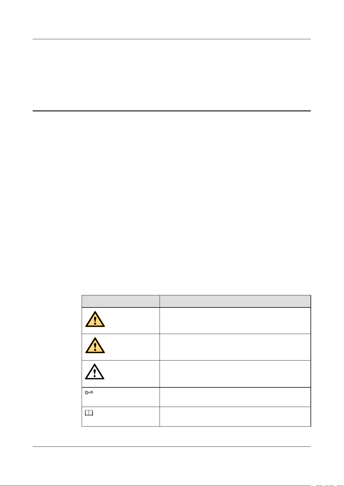
Symbol Conventions
The symbols that may be found in this document are defined as follows.
Symbol
Description
Indicates a hazard with a high level of risk, which if not
avoided, will result in death or serious injury.
Indicates a hazard with a medium or low level of risk, which
if not avoided, could result in minor or moderate injury.
Indicates a potentially hazardous situation, which if not
avoided, could result in equipment damage, data loss,
performance degradation, or unexpected results.
Indicates a tip that may help you solve a problem or save
time.
Provides additional information to emphasize or supplement
important points of the main text.
Issue 01 (2011-07-15) Huawei Proprietary and Confidential
Copyright © Huawei Technologies Co., Ltd.
ii

Quidway S7700 Smart Routing Switch
Configuration Guide - Ethernet About This Document
Command Conventions
The command conventions that may be found in this document are defined as follows.
Convention Description
Boldface The keywords of a command line are in boldface.
Italic Command arguments are in italics.
[ ] Items (keywords or arguments) in brackets [ ] are optional.
{ x | y | ... } Optional items are grouped in braces and separated by vertical
bars. One item is selected.
[ x | y | ... ] Optional items are grouped in brackets and separated by vertical
bars. One item is selected or no item is selected.
{ x | y | ... }
[ x | y | ... ]
&<1-n> The parameter before the & sign can be repeated 1 to n times.
# A line starting with the # sign is comments.
*
*
Change History
Updates between document issues are cumulative. Therefore, the latest document issue contains
all updates made in previous issues.
Changes in Issue 01 (2011-07-15)
Initial commercial release.
Optional items are grouped in braces and separated by vertical
bars. A minimum of one item or a maximum of all items can be
selected.
Optional items are grouped in brackets and separated by vertical
bars. Several items or no item can be selected.
Issue 01 (2011-07-15) Huawei Proprietary and Confidential
Copyright © Huawei Technologies Co., Ltd.
iii

Quidway S7700 Smart Routing Switch
Configuration Guide - Ethernet Contents
Contents
About This Document.....................................................................................................................ii
1 Ethernet Interface Configuration...............................................................................................1
1.1 Introduction to Ethernet Interfaces.....................................................................................................................2
1.2 Ethernet Interface Features Supported by the S7700.........................................................................................2
1.3 Configuring Basic Attributes of the Ethernet Interface......................................................................................3
1.3.1 Establishing the Configuration Task.........................................................................................................3
1.3.2 (Optional) Configuring a Description for an Interface..............................................................................3
1.3.3 (Optional) Configuring the Cable Type on an Interface............................................................................4
1.3.4 (Optional) Setting the Duplex Mode.........................................................................................................5
1.3.5 (Optional) Setting the Rate of an Interface................................................................................................5
1.3.6 (Optional) Enabling Auto-Negotiation......................................................................................................6
1.3.7 (Optional) Switching Between Optical and Electrical Interfaces..............................................................6
1.3.8 (Optional) Configuring an Interface to Work at Layer 2 or Layer 3.........................................................7
1.3.9 Checking the Configuration.......................................................................................................................7
1.4 Configuring Advanced Attributes of an Ethernet Interface................................................................................8
1.4.1 Establishing the Configuration Task.........................................................................................................8
1.4.2 (Optional) Configuring Loopback on the Ethernet Interface....................................................................9
1.4.3 (Optional) Setting the Minimum Interval for Re-enabling an Interface....................................................9
1.4.4 (Optional) Configuring the Interface Group..............................................................................................9
1.4.5 (Optional) Setting the Maximum Frame Length on the Ethernet Interface.............................................10
1.4.6 (Optional) Enabling Flow Control...........................................................................................................10
1.4.7 (Optional) Enabling Auto-Negotiation of Flow Control.........................................................................11
1.4.8 (Optional) Enabling Port Isolation..........................................................................................................11
1.4.9 (Optional) Performing a Cable Test on an Interface...............................................................................12
1.4.10 (Optional) Assigning an IP Address to an Ethernet Sub-interface........................................................13
1.4.11 Checking the Configuration...................................................................................................................13
1.5 Maintaining Ethernet Interfaces.......................................................................................................................14
1.5.1 Debugging Ethernet Interfaces................................................................................................................14
1.6 Configuration Examples...................................................................................................................................14
1.6.1 Example for Configuring Port Isolation..................................................................................................14
2 Link Aggregation Configuration..............................................................................................17
2.1 Introduction to Link Aggregation.....................................................................................................................18
Issue 01 (2011-07-15) Huawei Proprietary and Confidential
Copyright © Huawei Technologies Co., Ltd.
iv

Quidway S7700 Smart Routing Switch
Configuration Guide - Ethernet Contents
2.2 Link Aggregation Supported by the S7700......................................................................................................18
2.3 Configuring Link Aggregation in Manual Load Balancing Mode...................................................................19
2.3.1 Establishing the Configuration Task.......................................................................................................19
2.3.2 Configuring the Eth-Trunk to Work in Manual Load Balancing Mode..................................................20
2.3.3 Adding Member Interfaces to an Eth-Trunk...........................................................................................21
2.3.4 (Optional) Configuring the Load Balancing Mode.................................................................................22
2.3.5 (Optional) Limiting the Number of Active Interfaces.............................................................................23
2.3.6 (Optional) Configuring a Profile of Enhanced Eth-Trunks in Load Balancing Mode............................24
2.3.7 (Optional) Configuring the Load Balancing Mode for Unknown Unicast Traffic..................................25
2.3.8 Checking the Configuration.....................................................................................................................26
2.4 Configuring Link Aggregation in Static LACP Mode.....................................................................................26
2.4.1 Establishing the Configuration Task.......................................................................................................26
2.4.2 Configuring the Eth-Trunk to Work in Static LACP Mode....................................................................27
2.4.3 Adding Member Interfaces to an Eth-Trunk...........................................................................................27
2.4.4 (Optional) Configuring the Load Balancing Mode.................................................................................29
2.4.5 (Optional) Limiting the Number of Active Interfaces.............................................................................30
2.4.6 (Optional) Setting the LACP Priority of the System...............................................................................31
2.4.7 (Optional) Setting the LACP Priority of an Interface..............................................................................31
2.4.8 (Optional) Enabling LACP Preemption and Setting the Delay for LACP Preemption...........................32
2.4.9 (Optional) Setting the Timeout Interval for Receiving LACP Packets...................................................33
2.4.10 (Optional) Configuring a Profile of Enhanced Eth-Trunks in Load Balancing Mode..........................33
2.4.11 (Optional) Configuring the Load Balancing Mode for Unknown Unicast Traffic................................34
2.4.12 Checking the Configuration...................................................................................................................35
2.5 Configuring an Eth-Trunk Sub-interface..........................................................................................................35
2.5.1 Establishing the Configuration Task.......................................................................................................35
2.5.2 Creating an Eth-Trunk Sub-interface.......................................................................................................36
2.5.3 Setting the IP Address of an Eth-Trunk Sub-interface............................................................................36
2.5.4 Checking the Configuration.....................................................................................................................37
2.6 Configuring an E-Trunk...................................................................................................................................37
2.6.1 Establishing the Configuration Task.......................................................................................................37
2.6.2 Setting the LACP System ID and LACP Priority of an E-Trunk............................................................38
2.6.3 Creating an E-Trunk and Setting Its Priority...........................................................................................39
2.6.4 Configuring Local and Peer IP Addresses of an E-Trunk.......................................................................39
2.6.5 Binding an E-Trunk to a BFD Session....................................................................................................40
2.6.6 Adding an Eth-Trunk to an E-Trunk.......................................................................................................41
2.6.7 (Optional) Configuring the Working Mode of an Eth-Trunk in an E-Trunk..........................................41
2.6.8 (Optional) Setting the Password..............................................................................................................42
2.6.9 (Optional) Setting the Timeout of Hello Packets....................................................................................43
2.6.10 (Optional) Setting the Revertive Switching Delay................................................................................44
2.6.11 Checking the Configuration...................................................................................................................44
2.7 Maintaining Link Aggregation.........................................................................................................................45
2.7.1 Clearing Statistics of LACP Packets.......................................................................................................45
Issue 01 (2011-07-15) Huawei Proprietary and Confidential
Copyright © Huawei Technologies Co., Ltd.
v

Quidway S7700 Smart Routing Switch
Configuration Guide - Ethernet Contents
2.7.2 Debugging the Link Aggregation Group.................................................................................................45
2.7.3 Monitoring the Operation Status of the Link Aggregation Group..........................................................46
2.8 Configuration Examples...................................................................................................................................46
2.8.1 Example for Configuring Link Aggregation in Manual Load Balancing Mode.....................................46
2.8.2 Example for Configuring Link Aggregation in Static LACP Mode.......................................................49
2.8.3 Example for Connecting an E-Trunk to a VPLS Network......................................................................52
3 VLAN Configuration..................................................................................................................62
3.1 Introduction......................................................................................................................................................64
3.2 VLAN Features Supported by the S7700.........................................................................................................71
3.3 Dividing a LAN into VLANs...........................................................................................................................75
3.3.1 Establishing the Configuration Task.......................................................................................................75
3.3.2 Dividing a LAN into VLANs Based on Ports.........................................................................................78
3.3.3 Dividing a LAN into VLANs Based on MAC Addresses.......................................................................80
3.3.4 Dividing a LAN into VLANs Based on IP Subnets................................................................................81
3.3.5 Dividing a LAN into VLANs Based on Protocols..................................................................................83
3.3.6 Dividing a LAN into VLANs Based on Policies.....................................................................................85
3.3.7 Checking the Configuration.....................................................................................................................86
3.4 Creating a VLANIF Interface...........................................................................................................................87
3.4.1 Establishing the Configuration Task.......................................................................................................87
3.4.2 Creating a VLANIF Interface..................................................................................................................87
3.4.3 Assigning an IP Address to a VLANIF Interface....................................................................................88
3.4.4 (Optional) Setting a Delay After Which a VLANIF Interface Goes Down............................................88
3.4.5 (Optional) Setting the MTU of a VLANIF Interface...............................................................................89
3.4.6 Checking the Configuration.....................................................................................................................90
3.5 Configuring Inter-VLAN Communication.......................................................................................................90
3.5.1 Establishing the Configuration Task.......................................................................................................90
3.5.2 Configuring VLANIF Interfaces for Inter-VLAN Communication........................................................92
3.5.3 Configuring Sub-interface for Inter-VLAN Communication..................................................................93
3.5.4 Configuring VLAN Switch for Inter-VLAN Communication................................................................94
3.5.5 Checking the Configuration.....................................................................................................................95
3.6 Configuring VLAN Aggregation to Save IP Addresses...................................................................................96
3.6.1 Establishing the Configuration Task.......................................................................................................96
3.6.2 Creating a Sub-VLAN.............................................................................................................................97
3.6.3 Creating a Super-VLAN..........................................................................................................................98
3.6.4 Assigning an IP Address to the VLANIF Interface of a Super-VLAN...................................................99
3.6.5 (Optional) Enabling Proxy ARP on the VLANIF Interface of a Super-VLAN......................................99
3.6.6 Checking the Configuration...................................................................................................................100
3.7 Configuring a MUX VLAN to Separate Layer 2 Traffic...............................................................................100
3.7.1 Establishing the Configuration Task.....................................................................................................101
3.7.2 Configuring a Principal VLAN for a MUX VLAN..............................................................................102
3.7.3 Configuring a Group VLAN for a Subordinate VLAN.........................................................................103
3.7.4 Configuring a Separate VLAN for a Subordinate VLAN.....................................................................103
Issue 01 (2011-07-15) Huawei Proprietary and Confidential
Copyright © Huawei Technologies Co., Ltd.
vi

Quidway S7700 Smart Routing Switch
Configuration Guide - Ethernet Contents
3.7.5 Enabling the MUX VLAN Function on a Port......................................................................................104
3.7.6 Checking the Configuration...................................................................................................................105
3.8 Configuring a Voice VLAN to Transmit Voice Data.....................................................................................105
3.8.1 Establishing the Configuration Task.....................................................................................................105
3.8.2 Enabling the Voice VLAN Function.....................................................................................................107
3.8.3 Configuring an OUI for a Voice VLAN................................................................................................107
3.8.4 (Optional) Setting an Aging Timer for a Voice VLAN.........................................................................108
3.8.5 (Optional) Configuring an 802.1p Priority and a DSCP Value for the Voice VLAN...........................109
3.8.6 (Optional) Configuring the Mode in Which Ports Are Added to a Voice VLAN.................................109
3.8.7 (Optional) Configuring the Working Mode for a Voice VLAN............................................................111
3.8.8 (Optional) Configuring a Port to Communicate with a Voice Device of Another Vendor...................112
3.8.9 Checking the Configuration...................................................................................................................112
3.9 Configuring an mVLAN to Implement Integrated Management...................................................................113
3.9.1 Establishing the Configuration Task.....................................................................................................113
3.9.2 Configuring an mVLAN........................................................................................................................113
3.9.3 Configuring a VLANIF Interface for an mVLAN................................................................................114
3.9.4 Checking the Configuration...................................................................................................................115
3.10 Configuring VLAN Transparent Transport..................................................................................................115
3.10.1 Establishing the Configuration Task...................................................................................................115
3.10.2 Enabling VLAN Transparent Transport..............................................................................................116
3.10.3 Checking the Configuration.................................................................................................................117
3.11 Maintaining VLAN.......................................................................................................................................117
3.11.1 Clearing the Statistics of VLAN Packets............................................................................................117
3.12 Configuration Examples...............................................................................................................................118
3.12.1 Example for Configuring Interface-based VLANs..............................................................................118
3.12.2 Example for Configuring MAC Address-based VLAN Assignment..................................................120
3.12.3 Example for Configuring IP Subnet-based VLAN Assignment.........................................................122
3.12.4 Example for Configuring Protocol-based VLAN Assignment............................................................126
3.12.5 Example for Implementing Communication Between VLANs by Using VLANIF Interfaces...........129
3.12.6 Example for Configuring Communication Across a Layer 3 Network Through VLANIF Interfaces
........................................................................................................................................................................131
3.12.7 Example for Implementing Communication Between VLANs Through Sub-interfaces....................135
3.12.8 Example for Configuring Communication Across a Layer 3 Network Through the Sub-interface
........................................................................................................................................................................137
3.12.9 Example for Implementing Communication Between VLANs Through VLAN Switching..............140
3.12.10 Example for Configuring VLAN Aggregation..................................................................................142
3.12.11 Example for Configuring the MUX VLAN......................................................................................145
3.12.12 Example for Configuring a Voice VLAN in Auto Mode..................................................................147
3.12.13 Example for Configuring a Voice VLAN in Manual Mode..............................................................150
3.12.14 Example for Configuring VLAN Transparent Transmission............................................................153
4 VLAN Mapping Configuration..............................................................................................158
4.1 Introduction to VLAN Mapping.....................................................................................................................159
4.2 VLAN Mapping Features Supported by the S7700........................................................................................159
Issue 01 (2011-07-15) Huawei Proprietary and Confidential
Copyright © Huawei Technologies Co., Ltd.
vii

Quidway S7700 Smart Routing Switch
Configuration Guide - Ethernet Contents
4.3 Configuring VLAN Mapping of Single VLAN Tag......................................................................................159
4.3.1 Establishing the Configuration Task.....................................................................................................159
4.3.2 Replacing a Single Tag..........................................................................................................................160
4.3.3 Checking the Configuration...................................................................................................................161
4.4 Configuring VLAN Mapping of Double VLAN Tags...................................................................................161
4.4.1 Establishing the Configuration Task.....................................................................................................161
4.4.2 Replacing Double Tags.........................................................................................................................162
4.4.3 Replacing the Outer VLAN Tag............................................................................................................162
4.4.4 Checking the Configuration...................................................................................................................163
4.5 Configuring Flow-based VLAN Mapping.....................................................................................................163
4.5.1 Establishing the Configuration Task.....................................................................................................163
4.5.2 Replacing a Single Tag..........................................................................................................................164
4.5.3 Replacing Double Tags.........................................................................................................................166
4.5.4 Replacing the Outer VLAN Tag............................................................................................................169
4.5.5 Checking the Configuration...................................................................................................................171
4.6 Configuring VLAN Mapping Based On the VLAN Priority.........................................................................172
4.6.1 Establishing the Configuration Task.....................................................................................................172
4.6.2 Configuring VLAN Mapping Based on the VLAN Priority on the Incoming Interface.......................172
4.6.3 (Optional) Configuring VLAN Priority Mapping on the Outbound Interface......................................173
4.6.4 Checking the Configuration...................................................................................................................174
4.7 Configuration Examples.................................................................................................................................174
4.7.1 Example for Configuring Mapping of Single VLAN Tag....................................................................174
4.7.2 Example for Configuring N:1 VLAN Mapping....................................................................................178
4.7.3 Example for Configuring Mapping of Double VLAN Tags (2 to 2).....................................................180
4.7.4 Example for Configuring Flow-based VLAN Mapping........................................................................183
5 QinQ Configuration..................................................................................................................188
5.1 Concept of QinQ.............................................................................................................................................190
5.2 QinQ Features Supported by the S7700.........................................................................................................190
5.3 Configuring QinQ on an Interface..................................................................................................................190
5.3.1 Establishing the Configuration Task.....................................................................................................190
5.3.2 Setting the Link Type of an Interface....................................................................................................191
5.3.3 Specifying the Outer VLAN ID.............................................................................................................192
5.3.4 Checking the Configuration...................................................................................................................192
5.4 Configuring Selective QinQ...........................................................................................................................192
5.4.1 Establishing the Configuration Task.....................................................................................................192
5.4.2 Setting the Link Type of an Interface....................................................................................................193
5.4.3 Adding an Outer VLAN Tag.................................................................................................................193
5.4.4 Configuring Selective QinQ..................................................................................................................194
5.4.5 Checking the Configuration...................................................................................................................195
5.5 Configuring Flow-based Selective QinQ.......................................................................................................195
5.5.1 Establishing the Configuration Task.....................................................................................................195
5.5.2 Setting the Link Type of an Interface....................................................................................................195
Issue 01 (2011-07-15) Huawei Proprietary and Confidential
Copyright © Huawei Technologies Co., Ltd.
viii

Quidway S7700 Smart Routing Switch
Configuration Guide - Ethernet Contents
5.5.3 Setting the Packet Matching Rule.........................................................................................................196
5.5.4 Adding an Outer VLAN Tag.................................................................................................................196
5.5.5 Configuring a Traffic Policy..................................................................................................................197
5.5.6 Applying the Traffic Policy...................................................................................................................197
5.5.7 Checking the Configuration...................................................................................................................198
5.6 Configuring VLAN Stacking Based On the VLAN Priority..........................................................................198
5.6.1 Establishing the Configuration Task.....................................................................................................198
5.6.2 Configuring VLAN Stacking Based on the VLAN Priority on the Incoming Interface.......................199
5.6.3 (Optional) Configuring VLAN Priority Mapping on the Outbound Interface......................................199
5.6.4 Checking the Configuration...................................................................................................................200
5.7 Setting the Protocol Type in the Outer VLAN Tag........................................................................................200
5.7.1 Establishing the Configuration Task.....................................................................................................200
5.7.2 Configuring the Type of an Interface....................................................................................................201
5.7.3 Setting the Protocol Type in the Outer VLAN Tag...............................................................................201
5.7.4 Checking the Configuration...................................................................................................................202
5.8 Adding Double VLAN Tags to Untagged Packets.........................................................................................202
5.8.1 Establishing the Configuration Task.....................................................................................................202
5.8.2 Setting the Interface Type......................................................................................................................203
5.8.3 Adding an Interface to the Outer VLAN...............................................................................................203
5.8.4 Adding Double VLAN Tags to Untagged Packets................................................................................204
5.8.5 Checking the Configuration...................................................................................................................205
5.9 Connecting Sub-interfaces to a VLL Network...............................................................................................205
5.9.1 Establishing the Configuration Task.....................................................................................................205
5.9.2 Configuring a Dot1q Sub-interface.......................................................................................................206
5.9.3 Configuring a QinQ Sub-interface........................................................................................................206
5.9.4 Configuring VLAN Mapping of a Single Tag on a Sub-interface........................................................207
5.9.5 Configuring VLAN Mapping of Double Tags on a Sub-interface........................................................207
5.9.6 Configuring VLAN Stacking on a Sub-interface..................................................................................207
5.9.7 Creating a VLL Connection..................................................................................................................208
5.9.8 Checking the Configuration...................................................................................................................208
5.10 Connecting Sub-interfaces to a VPLS Network...........................................................................................208
5.10.1 Establishing the Configuration Task...................................................................................................209
5.10.2 Configuring a Dot1q Sub-interface.....................................................................................................209
5.10.3 Configuring a QinQ Sub-interface......................................................................................................210
5.10.4 Configuring VLAN Mapping of a Single Tag on a Sub-interface......................................................210
5.10.5 Configuring VLAN Mapping of Double Tags on a Sub-interface......................................................211
5.10.6 Configuring VLAN Stacking on a Sub-interface................................................................................211
5.10.7 Configuring VPLS...............................................................................................................................211
5.10.8 Checking the Configuration.................................................................................................................212
5.11 Configuring a Sub-interface to Access an L3VPN.......................................................................................212
5.11.1 Establishing the Configuration Task...................................................................................................212
5.11.2 Configuring a Dot1q Sub-interface.....................................................................................................213
Issue 01 (2011-07-15) Huawei Proprietary and Confidential
Copyright © Huawei Technologies Co., Ltd.
ix

Quidway S7700 Smart Routing Switch
Configuration Guide - Ethernet Contents
5.11.3 Configuring a QinQ Sub-interface......................................................................................................214
5.11.4 Configuring L3VPN............................................................................................................................215
5.11.5 Checking the Configuration.................................................................................................................215
5.12 Configuration Examples...............................................................................................................................215
5.12.1 Example for Configuring QinQ on Interfaces.....................................................................................215
5.12.2 Example for Configuring Selective QinQ...........................................................................................218
5.12.3 Example for Configuring Selective QinQ with VLAN Mapping........................................................221
5.12.4 Example for Configuring Selective QinQ with a Traffic Policy.........................................................224
5.12.5 Example for Configuring Flow-based Selective QinQ........................................................................227
5.12.6 Example for Configuring the Dot1q Sub-interfaces to Access VLL...................................................232
5.12.7 Example for Connecting QinQ Sub-interfaces to a VLL Network.....................................................238
5.12.8 Example for Connecting a Sub-interface Enabled with the Single-Tag VLAN Mapping to a VLL Network
........................................................................................................................................................................245
5.12.9 Example for Connecting a Sub-interface Enabled with Double-Tag VLAN Mapping to a VLL Network
........................................................................................................................................................................251
5.12.10 Example for Connecting a Sub-interface Enabled with VLAN Stacking to a VLL Network...........259
5.12.11 Example for Connecting Dot1q Sub-interfaces to a VPLS Network................................................266
5.12.12 Example for Connecting QinQ Sub-interfaces to a VPLS Network.................................................273
5.12.13 Example for Connecting a Sub-interface Enabled with Single-Tag VLAN Mapping to a VPLS Network
........................................................................................................................................................................280
5.12.14 Example for Connecting a Sub-interface Enabled with Double-Tag VLAN Mapping to a VPLS
Network..........................................................................................................................................................286
5.12.15 Example for Connecting a Sub-interface Enabled with VLAN Stacking to a VPLS Network.........294
5.12.16 Example for Configuring the Dot1q Sub-interface to Access an L3VPN.........................................301
5.12.17 Example for Configuring the QinQ Sub-interface to Access an L3VPN..........................................314
6 GVRP Configuration................................................................................................................329
6.1 GVRP Overview.............................................................................................................................................330
6.2 GVRP Features Supported by the S7700.......................................................................................................333
6.3 Configuring GVRP.........................................................................................................................................334
6.3.1 Establishing the Configuration Task.....................................................................................................334
6.3.2 Enabling GVRP.....................................................................................................................................334
6.3.3 (Optional) Setting the Registration Mode of a GVRP Interface............................................................335
6.3.4 (Optional) Setting the GARP Timers....................................................................................................336
6.3.5 Checking the Configuration...................................................................................................................337
6.4 Maintaining GVRP.........................................................................................................................................337
6.4.1 Clearing GARP Statistics......................................................................................................................337
6.5 Configuration Examples.................................................................................................................................338
6.5.1 Example for Configuring GVRP...........................................................................................................338
7 MAC Address Table Configuration.......................................................................................342
7.1 MAC Address Table Overview......................................................................................................................344
7.2 MAC Address Features Supported by the S7700...........................................................................................345
7.3 Configuring a Static MAC Address Entry......................................................................................................347
7.4 Configuring a Blackhole MAC Address Entry...............................................................................................348
Issue 01 (2011-07-15) Huawei Proprietary and Confidential
Copyright © Huawei Technologies Co., Ltd.
x

Quidway S7700 Smart Routing Switch
Configuration Guide - Ethernet Contents
7.5 Setting the Aging Time of Dynamic MAC Address Entries..........................................................................349
7.6 Disabling MAC Address Learning.................................................................................................................350
7.6.1 Establishing the Configuration Task.....................................................................................................350
7.6.2 Disabling MAC Address Learning on an Interface...............................................................................351
7.6.3 Disabling MAC Address Learning in a VLAN.....................................................................................352
7.6.4 Checking the Configuration...................................................................................................................352
7.7 Limiting the Number of Learned MAC Addresses........................................................................................352
7.7.1 Establishing the Configuration Task.....................................................................................................353
7.7.2 Limiting the Number of MAC Addresses Learned on an Interface......................................................354
7.7.3 Limiting the Number of MAC Addresses Learned in a VLAN............................................................355
7.7.4 Limiting the Number of MAC Addresses Learned in a VSI.................................................................356
7.7.5 Limiting the Number of MAC Addresses Learned in a Slot.................................................................357
7.7.6 Checking the Configuration...................................................................................................................357
7.8 Configuring Port Security...............................................................................................................................358
7.8.1 Establishing the Configuration Task.....................................................................................................358
7.8.2 Configuring the Secure Dynamic MAC Function on an Interface........................................................359
7.8.3 Configuring the Sticky MAC Function on an Interface........................................................................360
7.8.4 Checking the Configuration...................................................................................................................361
7.9 Configuring MAC Address Anti-Flapping.....................................................................................................361
7.9.1 Establishing the Configuration Task.....................................................................................................361
7.9.2 Setting the MAC Address Learning Priority of an Interface.................................................................362
7.9.3 Prohibiting MAC Address Flapping Between Interfaces with the Same Priority.................................363
7.9.4 Checking the Configuration...................................................................................................................363
7.10 Configuring MAC Address Flapping Detection...........................................................................................364
7.10.1 Establishing the Configuration Task...................................................................................................364
7.10.2 Configuring MAC Address Flapping Detection..................................................................................365
7.10.3 (Optional) Unblocking a Blocked Interface or MAC Address............................................................365
7.10.4 Checking the Configuration.................................................................................................................366
7.11 Configuring the S7700 to Discard Packets with an All-0 MAC Address....................................................366
7.12 Enabling MAC Address Triggered ARP Entry Update................................................................................367
7.13 Enabling Port Bridge....................................................................................................................................368
7.14 Configuration Examples...............................................................................................................................369
7.14.1 Example for Configuring the MAC Address Table.............................................................................369
7.14.2 Example for Configuring the Limitation on MAC Address Learning Based on VLANs...................372
7.14.3 Example for Configuring the Limitation on MAC Address Learning Based on VSIs........................374
7.14.4 Example for Configuring Interface Security.......................................................................................375
7.14.5 Example for Configuring MAC Address Anti-Flapping.....................................................................377
8 STP/RSTP Configuration.........................................................................................................380
8.1 STP/RSTP Overview......................................................................................................................................381
8.1.1 STP/RSTP Overview.............................................................................................................................381
8.1.2 STP/RSTP Features Supported by the S7700........................................................................................386
8.2 Configuring Basic STP/RSTP Functions.......................................................................................................388
Issue 01 (2011-07-15) Huawei Proprietary and Confidential
Copyright © Huawei Technologies Co., Ltd.
xi

Quidway S7700 Smart Routing Switch
Configuration Guide - Ethernet Contents
8.2.1 Establishing the Configuration Task.....................................................................................................388
8.2.2 Configuring the STP/RSTP Mode.........................................................................................................390
8.2.3 (Optional) Configuring Switching Device Priorities.............................................................................390
8.2.4 (Optional) Setting the Path Cost for a Port............................................................................................391
8.2.5 (Optional) Configuring Port Priorities...................................................................................................392
8.2.6 Enabling STP/RSTP..............................................................................................................................393
8.2.7 Checking the Configuration...................................................................................................................393
8.3 Configuring STP/RSTP Parameters on an Interface......................................................................................394
8.3.1 Establishing the Configuration Task.....................................................................................................396
8.3.2 Setting System Parameters....................................................................................................................397
8.3.3 Setting Port Parameters.........................................................................................................................398
8.3.4 Checking the Configuration...................................................................................................................400
8.4 Configuring RSTP Protection Functions........................................................................................................400
8.4.1 Establishing the Configuration Task.....................................................................................................400
8.4.2 Configuring BPDU Protection on a Switching Device.........................................................................402
8.4.3 Configuring TC Protection on a Switching Device...............................................................................403
8.4.4 Configuring Root Protection on a Port..................................................................................................403
8.4.5 Configuring Loop Protection on a Port.................................................................................................404
8.4.6 Checking the Configuration...................................................................................................................405
8.5 Configuring STP/RSTP Interoperability Between Huawei Devices and Non-Huawei Devices....................405
8.5.1 Establishing the Configuration Task.....................................................................................................405
8.5.2 Configuring the Proposal/Agreement Mechanism................................................................................406
8.5.3 Checking the Configuration...................................................................................................................407
8.6 Maintaining STP/RSTP..................................................................................................................................407
8.6.1 Clearing STP/RSTP Statistics...............................................................................................................408
8.7 Configuration Examples.................................................................................................................................408
8.7.1 Example for Configuring Basic STP Functions....................................................................................408
8.7.2 Example for Configuring Basic RSTP Functions..................................................................................412
9 MSTP Configuration.................................................................................................................417
9.1 MSTP Overview.............................................................................................................................................419
9.1.1 MSTP Introduction................................................................................................................................419
9.1.2 MSTP Features Supported by the S7700...............................................................................................427
9.2 Configuring Basic MSTP Functions...............................................................................................................431
9.2.1 Establishing the Configuration Task.....................................................................................................431
9.2.2 Configuring the MSTP Mode................................................................................................................433
9.2.3 Configuring and Activating an MST Region........................................................................................434
9.2.4 (Optional) Setting a Priority for a Switching Device in an MSTI.........................................................435
9.2.5 (Optional) Setting a Path Cost of a Port in an MSTI.............................................................................436
9.2.6 (Optional) Setting a Port Priority in an MSTI.......................................................................................437
9.2.7 Enabling MSTP.....................................................................................................................................438
9.2.8 Checking the Configuration...................................................................................................................438
9.3 Configuring MSTP Multi-process..................................................................................................................439
Issue 01 (2011-07-15) Huawei Proprietary and Confidential
Copyright © Huawei Technologies Co., Ltd.
xii

Quidway S7700 Smart Routing Switch
Configuration Guide - Ethernet Contents
9.3.1 Establishing the Configuration Task.....................................................................................................439
9.3.2 Creating an MSTP Process....................................................................................................................440
9.3.3 Adding an Interface to an MSTP Process - Access Links.....................................................................441
9.3.4 Adding an Interface to an MSTP Process - Share Link.........................................................................441
9.3.5 Configuring Priorities and Root Protection in MSTP Multi-process....................................................442
9.3.6 Configuring TC Notification in MSTP Multi-process..........................................................................442
9.3.7 Checking the Configuration...................................................................................................................443
9.4 Configuring MSTP Parameters on an Interface.............................................................................................443
9.4.1 Establishing the Configuration Task.....................................................................................................443
9.4.2 Configuring System Parameters............................................................................................................444
9.4.3 Configuring Port Parameters.................................................................................................................446
9.4.4 Checking the Configuration...................................................................................................................447
9.5 Configuring MSTP Protection Functions.......................................................................................................448
9.5.1 Establishing the Configuration Task.....................................................................................................448
9.5.2 Configuring BPDU Protection on a Switching Device.........................................................................450
9.5.3 Configuring TC Protection on a Switching Device...............................................................................450
9.5.4 Configuring Root Protection on an Interface........................................................................................451
9.5.5 Configuring Loop Protection on an Interface........................................................................................452
9.5.6 Configuring Share-Link Protection on a Switching Device..................................................................453
9.5.7 Checking the Configuration...................................................................................................................454
9.6 Configuring MSTP Interoperability Between Huawei Devices and Non-Huawei Devices...........................454
9.6.1 Establishing the Configuration Task.....................................................................................................454
9.6.2 Configuring a Proposal/Agreement Mechanism...................................................................................455
9.6.3 Configuring the MSTP Protocol Packet Format on an Interface...........................................................456
9.6.4 Enabling the Digest Snooping Function................................................................................................457
9.6.5 Checking the Configuration...................................................................................................................458
9.7 Maintaining MSTP.........................................................................................................................................458
9.7.1 Clearing MSTP Statistics.......................................................................................................................458
9.8 Configuration Examples.................................................................................................................................458
9.8.1 Example for Configuring Basic MSTP Functions.................................................................................458
9.8.2 Example for Connecting CEs to the VPLS in Dual-Homing Mode Through MSTP............................465
9.8.3 Example for Configuring MSTP Multi-Process for Layer 2 Single-Access Rings and Layer 2 Multi-Access
Rings...............................................................................................................................................................477
10 SEP Configuration...................................................................................................................485
10.1 SEP Overview...............................................................................................................................................487
10.1.1 SEP Overview......................................................................................................................................487
10.1.2 SEP Features Supported by the S7700................................................................................................500
10.2 Configuring Basic SEP Functions................................................................................................................506
10.2.1 Establishing the Configuration Task...................................................................................................506
10.2.2 Configuring an SEP Segment..............................................................................................................507
10.2.3 Configuring a Control VLAN..............................................................................................................507
10.2.4 Creating a Protected Instance..............................................................................................................508
Issue 01 (2011-07-15) Huawei Proprietary and Confidential
Copyright © Huawei Technologies Co., Ltd.
xiii

Quidway S7700 Smart Routing Switch
Configuration Guide - Ethernet Contents
10.2.5 Adding a Layer 2 Interface to a SEP Segment and Configuring a Role for the Interface...................509
10.2.6 Checking the Configuration.................................................................................................................511
10.3 Specifying an Interface to Block..................................................................................................................511
10.3.1 Establishing the Configuration Task...................................................................................................512
10.3.2 Setting an Interface Blocking Mode....................................................................................................512
10.3.3 Configuring the Preemption Mode......................................................................................................514
10.3.4 Checking the Configuration.................................................................................................................516
10.4 Configuring SEP Multi-Instance..................................................................................................................516
10.4.1 Establishing the Configuration Task...................................................................................................516
10.4.2 Configuring and Activating Mappings Between Protected Instances and VLANs.............................518
10.4.3 Checking the Configuration.................................................................................................................518
10.5 Configuring the Topology Change Notification Function...........................................................................519
10.5.1 Establishing the Configuration Task...................................................................................................519
10.5.2 Reporting Topology Changes of a Lower-Layer Network - SEP Topology Change Notification
........................................................................................................................................................................521
10.5.3 Reporting Topology Changes of a Lower-Layer Network - Enabling the Edge Devices in a SEP Segment
to Process SmartLink Flush Packets...............................................................................................................522
10.5.4 Reporting Topology Changes of an Upper-Layer Network - Configuring Association Between SEP and
CFM................................................................................................................................................................523
10.5.5 Checking the Configuration.................................................................................................................524
10.6 Maintaining SEP...........................................................................................................................................524
10.6.1 Clearing SEP Statistics........................................................................................................................524
10.6.2 Debugging SEP....................................................................................................................................524
10.7 Configuration Examples...............................................................................................................................525
10.7.1 Example for Configuring SEP on a Closed Ring Network.................................................................525
10.7.2 Example for Configuring SEP on a Multi-ring Network....................................................................531
10.7.3 Example for Configuring a Hybrid SEP+MSTP Ring Network.........................................................542
10.7.4 Example for Configuring a Hybrid SEP+RRPP Ring Network..........................................................549
10.7.5 Example for Configuring SEP Multi-Instance....................................................................................561
11 Layer 2 Protocol Transparent Transmission Configuration............................................569
11.1 Overview of Layer 2 Protocol Transparent Transmission............................................................................571
11.2 Layer 2 Protocol Transparent Transmission Features Supported by the S7700...........................................572
11.3 Configuring Interface-based Layer 2 Protocol Transparent Transmission...................................................578
11.3.1 Establishing the Configuration Task...................................................................................................578
11.3.2 (Optional) Defining Characteristic Information About a Layer 2 Protocol........................................578
11.3.3 Configuring the Transparent Transmission Mode of Layer 2 Protocol Packets.................................579
11.3.4 Enabling Layer 2 Protocol Transparent Transmission on an Interface...............................................580
11.3.5 Checking Configuration......................................................................................................................581
11.4 Configuring VLAN-based Layer 2 Protocol Transparent Transmission......................................................581
11.4.1 Establishing the Configuration Task...................................................................................................582
11.4.2 (Optional) Defining Characteristic Information About a Layer 2 Protocol........................................582
11.4.3 Configuring the Transparent Transmission Mode of Layer 2 Protocol Packets.................................583
11.4.4 Enabling VLAN-based Layer 2 Protocol Transparent Transmission on an Interface.........................584
Issue 01 (2011-07-15) Huawei Proprietary and Confidential
Copyright © Huawei Technologies Co., Ltd.
xiv

Quidway S7700 Smart Routing Switch
Configuration Guide - Ethernet Contents
11.4.5 Checking the Configuration.................................................................................................................585
11.5 Configuring QinQ-based Layer 2 Protocol Transparent Transmission........................................................585
11.5.1 Establishing the Configuration Task...................................................................................................585
11.5.2 (Optional) Defining Characteristic Information About a Layer 2 Protocol........................................586
11.5.3 Configuring the Transparent Transmission Mode of Layer 2 Protocol Packets.................................587
11.5.4 Enabling QinQ-based Layer 2 Transparent Transmission on an Interface..........................................588
11.5.5 Checking the Configuration.................................................................................................................588
11.6 Maintaining Layer 2 Protocol Transparent Transmission............................................................................589
11.6.1 Debugging Layer 2 Protocol Transparent Transmission.....................................................................589
11.7 Configuration Examples...............................................................................................................................589
11.7.1 Example for Configuring Interface-based Layer 2 Protocol Transparent Transmission.....................589
11.7.2 Example for Configuring VLAN-based Layer 2 Protocol Transparent Transmission........................596
11.7.3 Example for Configuring QinQ-based Layer 2 Protocol Transparent Transmission..........................602
12 HVRP Configuration..............................................................................................................610
12.1 HVRP Overview...........................................................................................................................................611
12.2 HVRP Features Supported by the S7700.....................................................................................................612
12.3 Enabling HVRP............................................................................................................................................615
12.3.1 Establishing the Configuration Task...................................................................................................615
12.3.2 Enabling HVRP Globally....................................................................................................................617
12.3.3 Enabling HVRP on an Interface..........................................................................................................617
12.3.4 (Optional) Setting the VLAN Registration Timer...............................................................................618
12.3.5 (Optional) Setting the Aging Time of Registered VLANs..................................................................618
12.3.6 (Optional) Configuring Permanent VLANs........................................................................................619
12.3.7 (Optional) Configuring the S7700 to Age All the VLANs.................................................................619
12.3.8 Checking the Configuration.................................................................................................................620
12.4 Maintaining HVRP.......................................................................................................................................620
12.4.1 Debugging HVRP................................................................................................................................620
12.5 Configuration Examples...............................................................................................................................621
12.5.1 Example for Configuring HVRP.........................................................................................................621
13 Loop Detection Configuration..............................................................................................624
13.1 Introduction to Loop Detection....................................................................................................................625
13.2 Configuring Loop Detection.........................................................................................................................625
13.2.1 Establishing the Configuration Task...................................................................................................625
13.2.2 Enabling Loop Detection Globally......................................................................................................626
13.2.3 Enabling Loop Detection in a VLAN..................................................................................................626
13.2.4 Enabling Loop Detection Control on an Interface...............................................................................627
13.2.5 (Optional) Disabling Loop Detection on an Interface.........................................................................628
13.2.6 (Optional) Setting the Loop Detection Interval on an Interface..........................................................628
13.2.7 (Optional) Setting the Recovery Time of a Blocked Interface............................................................628
13.2.8 Checking the Configuration.................................................................................................................629
13.3 Configuration Examples...............................................................................................................................630
Issue 01 (2011-07-15) Huawei Proprietary and Confidential
Copyright © Huawei Technologies Co., Ltd.
xv

Quidway S7700 Smart Routing Switch
Configuration Guide - Ethernet Contents
13.3.1 Example for Configuring Loop Detection...........................................................................................630
Issue 01 (2011-07-15) Huawei Proprietary and Confidential
Copyright © Huawei Technologies Co., Ltd.
xvi

Quidway S7700 Smart Routing Switch
Configuration Guide - Ethernet 1 Ethernet Interface Configuration
1 Ethernet Interface Configuration
About This Chapter
This chapter describes the basic knowledge, methods, and examples for configuring the Ethernet
interface.
1.1 Introduction to Ethernet Interfaces
This section describes the Ethernet interfaces.
1.2 Ethernet Interface Features Supported by the S7700
This section describes the Ethernet interface features supported by the S7700.
1.3 Configuring Basic Attributes of the Ethernet Interface
This section describes how to configure the description, cable type, duplex mode, rate, and autonegotiation an Ethernet interface, and switch between the optical and electrical interfaces and
between Layer 2 and Layer 3 interfaces.
1.4 Configuring Advanced Attributes of an Ethernet Interface
This section describes how to configure the loopback on the Ethernet Interface, minimum
interval for re-enabling an interface, port group, maximum frame size, flow control, flow control
auto-negotiation, cable test, sub-interface IP address, and port isolation.
1.5 Maintaining Ethernet Interfaces
This section describes how to maintain Ethernet interfaces.
1.6 Configuration Examples
This section provides several configuration examples of Ethernet interfaces.
Issue 01 (2011-07-15) Huawei Proprietary and Confidential
Copyright © Huawei Technologies Co., Ltd.
1
Quidway S7700 Smart Routing Switch
Configuration Guide - Ethernet 1 Ethernet Interface Configuration
1.1 Introduction to Ethernet Interfaces
This section describes the Ethernet interfaces.
The Ethernet is flexible, simple, and easy to implement; therefore, it becomes an important local
area network (LAN) networking technology.
Table 1-1 shows the attributes of Ethernet electrical interfaces and Ethernet optical interfaces.
Table 1-1 Attributes of Ethernet interfaces
Interface
Type
Ethernet
electrical
interface
Ethernet
optical
interface
If the local interface works in auto-negotiation mode, the peer interface must also work in autonegotiation mode; otherwise, packet loss may occur.
Rate (Mbit/s)Auto-negotiation Non-negotiation
Full
Duplex
10 Yes Yes Yes Yes
100 Yes Yes Yes Yes
1000 Yes No Yes No
100 No No Yes No
1000 Yes No Yes No
10000 No No Yes No
Half
Duplex
Full
Duplex
Half
Duplex
1.2 Ethernet Interface Features Supported by the S7700
This section describes the Ethernet interface features supported by the S7700.
Port Group
The port group function enables you to configure multiple interfaces at the same time. You can
run commands in the port group view to configure all the interfaces in the group.
Auto-Negotiation
The auto-negotiation function allows interfaces on both ends of a link to select the same operating
parameters by exchanging capability information. Each interface sends its capability information
to the remote end and checks capabilities of the remote end. After both interfaces receive the
capability information from each other, they adopt the highest capability they support to
communicate with each other.
The interfaces negotiate the duplex mode, speed, and flow control parameters. After a successful
negotiation, the interfaces use the same duplex mode, speed, and flow control parameters.
Issue 01 (2011-07-15) Huawei Proprietary and Confidential
Copyright © Huawei Technologies Co., Ltd.
2

Quidway S7700 Smart Routing Switch
Configuration Guide - Ethernet 1 Ethernet Interface Configuration
Port Isolation
The port isolation function isolates Layer 2 and Layer 3 communication between ports in the
same VLAN. This function restricts packet transmission between ports flexibly, providing a
secure and flexible network solution.
1.3 Configuring Basic Attributes of the Ethernet Interface
This section describes how to configure the description, cable type, duplex mode, rate, and autonegotiation an Ethernet interface, and switch between the optical and electrical interfaces and
between Layer 2 and Layer 3 interfaces.
1.3.1 Establishing the Configuration Task
Applicable Environment
The configuration task is applicable to the following situations:
l You can configure the description of interfaces to facilitate the identification, maintenance,
and configuration of the interfaces.
l By default, an FE electrical interface automatically identifies the network cable type. If the
interface cannot identify the cable type properly, set the cable type for the interface
manually.
l By default, an FE electrical interface negotiates the duplex mode and rate with the
equipment that is directly connected to the interface. If the connected equipment does not
have the auto-negotiation capability, set the duplex mode and rate for the FE interface
manually so that the interface can work with the connected equipment.
Pre-configuration Tasks
None
Data Preparation
To configure the basic functions of Ethernet interfaces, you need the following data.
No.
1 Number of an Ethernet interface
2 (Optional) Description of an interface
Data
3 (Optional) Cable type of an ethernet electrical interface
4 (Optional) Duplex mode of an ethernet electrical interface
5 (Optional) Rate of an ethernet interface
1.3.2 (Optional) Configuring a Description for an Interface
Issue 01 (2011-07-15) Huawei Proprietary and Confidential
Copyright © Huawei Technologies Co., Ltd.
3

Quidway S7700 Smart Routing Switch
Configuration Guide - Ethernet 1 Ethernet Interface Configuration
Context
Perform the following steps on the S7700.
Procedure
Step 1 Run:
system-view
The system view is displayed.
Step 2 Run:
interface interface-type interface-number
The interface view is displayed.
Step 3 Run:
description description
A description is configured for the interface.
By default, the description of an interface is "HUAWEI, Quidway Series, X interface". X
specifies the interface type and number.
----End
1.3.3 (Optional) Configuring the Cable Type on an Interface
Context
Perform the following steps on the S7700.
Procedure
Step 1 Run:
system-view
The system view is displayed.
Step 2 Run:
interface interface-type interface-number
The Ethernet electrical interface view is displayed.
Step 3 Run:
mdi { across | auto | normal }
The cable type is configured for the Ethernet electrical interface.
By default, an Ethernet electrical interface automatically identifies the cable type.
An electrical interface can use a crossover cable or a straight through cable. If across is specified,
the interface can use a crossover cable; if normal is specified, the interface can use a straight
through cable; if auto is specified, the interface can use both types of network cables.
----End
Issue 01 (2011-07-15) Huawei Proprietary and Confidential
Copyright © Huawei Technologies Co., Ltd.
4

Quidway S7700 Smart Routing Switch
Configuration Guide - Ethernet 1 Ethernet Interface Configuration
1.3.4 (Optional) Setting the Duplex Mode
Context
Do as follows on the S7700 where you need to set the duplex mode of interfaces.
Procedure
Step 1 Run:
system-view
The system view is displayed.
Step 2 Run:
interface interface-type interface-number
The Ethernet electrical interface view is displayed.
Step 3 Run:
undo negotiation auto
The auto-negotiation mode is disabled on the Ethernet electrical interface.
Step 4 Run:
duplex { full | half }
The duplex mode is set for the Ethernet electrical interface.
By default, the duplex mode of an Ethernet electrical interface is full-duplex when autonegotiation is disabled on the interface.
----End
1.3.5 (Optional) Setting the Rate of an Interface
Context
Do as follows on the S7700 where you need to set the rate of interfaces.
Procedure
Step 1 Run:
system-view
The system view is displayed.
Step 2 Run:
interface interface-type interface-number
The interface view is displayed.
Step 3 Run:
undo negotiation auto
The auto-negotiation mode is disabled on the interface.
Issue 01 (2011-07-15) Huawei Proprietary and Confidential
Copyright © Huawei Technologies Co., Ltd.
5

Quidway S7700 Smart Routing Switch
Configuration Guide - Ethernet 1 Ethernet Interface Configuration
Step 4 Run:
speed { 10 | 100 | 1000 }
The rate is set for the interface.
By default, an Ethernet interface works at its maximum rate when auto-negotiation is disabled
on the interface.
----End
1.3.6 (Optional) Enabling Auto-Negotiation
Context
Do as follows on the S7700 where you want to enable auto-negotiation and on the switch
connected to this S7700.
Procedure
Step 1 Run:
system-view
The system view is displayed.
Step 2 Run:
interface interface-type interface-number
The interface view is displayed.
Step 3 Run:
negotiation auto
Auto-negotiation is enabled on the interface.
By default, an interface works in auto-negotiation mode.
The local interface and peer interface must work in the same mode, that is, both in autonegotiation mode or not.
NOTE
100M and 10G optical interfaces do not support auto negotiation.
----End
1.3.7 (Optional) Switching Between Optical and Electrical Interfaces
Context
Do as follows on the S7700 where you need to switch between optical and electrical interfaces.
Procedure
Step 1 Run:
Issue 01 (2011-07-15) Huawei Proprietary and Confidential
Copyright © Huawei Technologies Co., Ltd.
6

Quidway S7700 Smart Routing Switch
Configuration Guide - Ethernet 1 Ethernet Interface Configuration
system-view
The system view is displayed.
Step 2 Run:
interface gigabitethernet interface-number
The GigabitEthernet interface view is displayed.
Step 3 Run:
combo-port { auto | copper | fiber }
The interface is changed to an optical interface or an electrical interface.
By default, a combo port selects the working mode automatically.
A G24C LPU has 8 electrical interface and 24 optical interfaces, among which the first 8 optical
interfaces are duplexed with electrical interfaces. You can use the combo-port command to use
these interfaces as electrical interfaces or optical interfaces.
----End
1.3.8 (Optional) Configuring an Interface to Work at Layer 2 or Layer 3
Procedure
Step 1 Run:
system-view
The system view is displayed.
Step 2 Run:
interface interface-type interface-number
The interface view is displayed.
Step 3 Run:
portswitch
The interface is configured to work at Layer 2.
Step 4 Run:
undo portswitch
The interface is configured to work at Layer 3.
By default, an Ethernet interface works at Layer 2.
When an Ethernet interface switches from Layer 3 to Layer 2, the Layer 3 functions and flag
are disabled. The MAC address of the system is used.
----End
1.3.9 Checking the Configuration
Issue 01 (2011-07-15) Huawei Proprietary and Confidential
Copyright © Huawei Technologies Co., Ltd.
7

Quidway S7700 Smart Routing Switch
Configuration Guide - Ethernet 1 Ethernet Interface Configuration
Procedure
Step 1 Run the display interface [ interface-type [ interface-number [.subnumber ] ] ] command to
display the description, duplex mode, and rate of an Ethernet interface.
----End
1.4 Configuring Advanced Attributes of an Ethernet Interface
This section describes how to configure the loopback on the Ethernet Interface, minimum
interval for re-enabling an interface, port group, maximum frame size, flow control, flow control
auto-negotiation, cable test, sub-interface IP address, and port isolation.
1.4.1 Establishing the Configuration Task
Applicable Environment
The configuration task is applicable to the following situations:
l The S7700 provides the interface group function, which enables you to configure multiple
interfaces at the same time.
l If the traffic volume received on an interface of the S7700 may exceed the processing
capability of the interface and the directly connected interface supports traffic control,
enable the traffic control function on the interface. When the rate of received traffic reaches
the threshold, the interface sends a Pause frame (in full duplex mode) or sends a back
pressure signal (in half duplex mode) to notify the peer interface. If the peer interface
supports traffic control, it decreases the rate of at which it sends traffic so that the local
interface can properly process received traffic.
l Ports enabled with port isolation cannot communicate with each other so that ports on the
same VLAN can be isolated. Port isolation provides secure and flexible networking
schemes for customers.
Pre-configuration Tasks
None.
Data Preparation
To configure the advanced functions of Ethernet interfaces, you need the following data.
No.
1 Interface number
2 (Optional) Maximum frame length allowed on the interface
Issue 01 (2011-07-15) Huawei Proprietary and Confidential
Data
Copyright © Huawei Technologies Co., Ltd.
8

Quidway S7700 Smart Routing Switch
Configuration Guide - Ethernet 1 Ethernet Interface Configuration
1.4.2 (Optional) Configuring Loopback on the Ethernet Interface
Context
Do as follows on the S7700 where you need to configure the loopback.
Procedure
Step 1 Run:
system-view
The system view is displayed.
Step 2 Run:
interface interface-type interface-number
The interface view is displayed.
Step 3 Run:
loopback internal
The loopback is configured on the Ethernet interface.
By default, loopback is not configured on an Ethernet interface.
----End
1.4.3 (Optional) Setting the Minimum Interval for Re-enabling an Interface
Context
Do as follows on the S7700 where you need to set the minimum interval for re-enabling an
interface.
Procedure
Step 1 Run:
system-view
The system view is displayed.
Step 2 Run:
shutdown interval interval-value
The minimum interval for re-enabling an interface is set.
By default, the minimum interval for re-enabling an interface after the interface is disabled is
0 seconds.
----End
1.4.4 (Optional) Configuring the Interface Group
Issue 01 (2011-07-15) Huawei Proprietary and Confidential
Copyright © Huawei Technologies Co., Ltd.
9

Quidway S7700 Smart Routing Switch
Configuration Guide - Ethernet 1 Ethernet Interface Configuration
Context
Do as follows on the S7700 where you need to configure interface groups.
Procedure
Step 1 Run:
system-view
The system view is displayed.
Step 2 Run:
port-group port-group-name
The interface group view is displayed.
Step 3 Run:
group-member interface-type interface-number
The Ethernet interface is added to the interface group.
----End
1.4.5 (Optional) Setting the Maximum Frame Length on the Ethernet Interface
Context
Do as follows on the S7700 where you need to set the maximum frame length.
Procedure
Step 1 Run:
system-view
The system view is displayed.
Step 2 Run:
interface interface-type interface-number
The Ethernet interface view is displayed.
Step 3 Run:
jumboframe enable [ value ]
The maximum length of the frame is set on the Ethernet interface.
By default, the maximum frame length allowed by an interface is 9216 bytes.
----End
1.4.6 (Optional) Enabling Flow Control
Context
Do as follows on the S7700 where you need to enable flow control.
Issue 01 (2011-07-15) Huawei Proprietary and Confidential
Copyright © Huawei Technologies Co., Ltd.
10

Quidway S7700 Smart Routing Switch
Configuration Guide - Ethernet 1 Ethernet Interface Configuration
Procedure
Step 1 Run:
system-view
The system view is displayed.
Step 2 Run:
interface interface-type interface-number
The interface view is displayed.
Step 3 Run:
flow-control
Flow control is enabled on the Ethernet interface.
By default, flow control is disabled on an Ethernet interface.
To implement flow control, you must enable this function on both the local interface and peer
interface.
----End
1.4.7 (Optional) Enabling Auto-Negotiation of Flow Control
Context
Do as follows on the S7700 whose interface needs to be configured with auto-negotiation of
flow control.
GE interfaces support auto-negotiation of flow control, but FE interfaces do not support this
function.
Procedure
Step 1 Run:
system-view
The system view is displayed.
Step 2 Run:
interface gigabitethernet interface-number
The GE interface view is displayed.
Step 3 Run:
flow-control negotiation
Auto-negotiation of flow control is enabled on the GE interface.
By default, auto-negotiation of flow control is disabled on a GE interface.
You also need to configure auto-negotiation of flow control on the peer interface.
----End
1.4.8 (Optional) Enabling Port Isolation
Issue 01 (2011-07-15) Huawei Proprietary and Confidential
Copyright © Huawei Technologies Co., Ltd.
11

Quidway S7700 Smart Routing Switch
Configuration Guide - Ethernet 1 Ethernet Interface Configuration
Context
Do as follows on the S7700 where you need to enable port isolation.
Procedure
Step 1 Run:
system-view
The system view is displayed.
Step 2 Run:
port-isolate mode { l2 | all }
The port isolation mode is set.
By default, ports are isolated on Layer 2 but can communicate on Layer 3.
Step 3 Run:
interface interface-type interface-number
The Ethernet interface view is displayed.
Step 4 (Optional) Run:
am isolate interface-type interface-number [ to interface-number ]
The Ethernet interface is isolated from another interface unidirectionally.
NOTE
After interface A is isolated from interface B unidirectionally, packets sent by interface A cannot reach
interface B, whereas packets sent from interface B can reach interface A.
Step 5 Run:
port-isolate enable [ group group-id ]
Port isolation is enabled.
NOTE
Ports in a port isolation group are isolated from each other, and ports in different port isolation groups can
communicate with each other. If group-id is not specified, a port is added to port isolation group 1.
----End
1.4.9 (Optional) Performing a Cable Test on an Interface
Context
A cable test detects faults on the cable connected to an interface. If the cable is working properly,
the total length of the cable is displayed. If the cable cannot work properly, the distance between
the interface and the fault point is displayed.
Procedure
Step 1 Run:
system-view
Issue 01 (2011-07-15) Huawei Proprietary and Confidential
Copyright © Huawei Technologies Co., Ltd.
12

Quidway S7700 Smart Routing Switch
Configuration Guide - Ethernet 1 Ethernet Interface Configuration
The system view is displayed.
Step 2 Run:
interface interface-type interface-number
The interface view is displayed.
Step 3 Run:
virtual-cable-test
A cable test is performed on the interface.
NOTE
l The test result is only for reference.
l Running the virtual-cable-test command may affect services on the interface in a short period of time.
l Before performing a cable test, shut down the remote interface or remove the network cable from the
remote interface. Otherwise, signals from the remote interface may make the test result inaccurate.
----End
1.4.10 (Optional) Assigning an IP Address to an Ethernet Subinterface
Procedure
Step 1 Run:
system-view
The system view is displayed.
Step 2 Run:
interface interface-type interface-number.subinterface-number
An Ethernet sub-interface is created and the Ethernet sub-interface view is displayed.
Step 3 Run:
ip address ip-address { mask | mask-length } [ sub ]
The IP address of the Ethernet sub-interface is configured.
Only the E-series and F-series boards supports the configuration of sub-interfaces.
----End
1.4.11 Checking the Configuration
Procedure
l Run the display port-group [ all | port-group-name ] command to check information about
a port group.
l Run the display interface [ interface-type [ interface-number [.subnumber ] ] ] command
to check information about auto-negotiation capability on an Ethernet interface.
l Run the display virtual-cable-test interface-type interface-number command to check the
cable test result on an Ethernet interface.
----End
Issue 01 (2011-07-15) Huawei Proprietary and Confidential
Copyright © Huawei Technologies Co., Ltd.
13
 Loading...