

Page 1

Quidway S6700 Series Ethernet Switches
V100R006C00
Configuration Guide - Reliability
Issue 01
Date 2011-07-15
HUAWEI TECHNOLOGIES CO., LTD.
Page 2

Copyright © Huawei Technologies Co., Ltd. 2011. All rights reserved.
No part of this document may be reproduced or transmitted in any form or by any means without prior written
consent of Huawei Technologies Co., Ltd.
Trademarks and Permissions
and other Huawei trademarks are trademarks of Huawei Technologies Co., Ltd.
All other trademarks and trade names mentioned in this document are the property of their respective holders.
Notice
The purchased products, services and features are stipulated by the contract made between Huawei and the
customer. All or part of the products, services and features described in this document may not be within the
purchase scope or the usage scope. Unless otherwise specified in the contract, all statements, information,
and recommendations in this document are provided "AS IS" without warranties, guarantees or representations
of any kind, either express or implied.
The information in this document is subject to change without notice. Every effort has been made in the
preparation of this document to ensure accuracy of the contents, but all statements, information, and
recommendations in this document do not constitute the warranty of any kind, express or implied.
Huawei Technologies Co., Ltd.
Address: Huawei Industrial Base
Bantian, Longgang
Shenzhen 518129
People's Republic of China
Website: http://www.huawei.com
Email: support@huawei.com
Issue 01 (2011-07-15) Huawei Proprietary and Confidential
Copyright © Huawei Technologies Co., Ltd.
i
Page 3
DANGER
WARNING
CAUTION
TIP
NOTE
Quidway S6700 Series Ethernet Switches
Configuration Guide - Reliability About This Document
About This Document
Intended Audience
This document provides the basic concepts, configuration procedures, and configuration
examples in different application scenarios of the reliability supported by the S6700.
This document describes how to configure the reliability.
This document is intended for:
l Data configuration engineers
l Commissioning engineers
l Network monitoring engineers
l System maintenance engineers
Symbol Conventions
The symbols that may be found in this document are defined as follows.
Symbol
Description
Indicates a hazard with a high level of risk, which if not
avoided, will result in death or serious injury.
Indicates a hazard with a medium or low level of risk, which
if not avoided, could result in minor or moderate injury.
Indicates a potentially hazardous situation, which if not
avoided, could result in equipment damage, data loss,
performance degradation, or unexpected results.
Indicates a tip that may help you solve a problem or save
time.
Provides additional information to emphasize or supplement
important points of the main text.
Issue 01 (2011-07-15) Huawei Proprietary and Confidential
Copyright © Huawei Technologies Co., Ltd.
ii
Page 4
Quidway S6700 Series Ethernet Switches
Configuration Guide - Reliability About This Document
Command Conventions
The command conventions that may be found in this document are defined as follows.
Convention Description
Boldface The keywords of a command line are in boldface.
Italic Command arguments are in italics.
[ ] Items (keywords or arguments) in brackets [ ] are optional.
{ x | y | ... } Optional items are grouped in braces and separated by
vertical bars. One item is selected.
[ x | y | ... ] Optional items are grouped in brackets and separated by
vertical bars. One item is selected or no item is selected.
{ x | y | ... }
[ x | y | ... ]
&<1-n> The parameter before the & sign can be repeated 1 to n times.
# A line starting with the # sign is comments.
*
*
Change History
Updates between document issues are cumulative. Therefore, the latest document issue contains
all changes made in previous issues.
Changes in Issue 01 (2011-07-15)
Initial commercial release.
Optional items are grouped in braces and separated by
vertical bars. A minimum of one item or a maximum of all
items can be selected.
Optional items are grouped in brackets and separated by
vertical bars. Several items or no item can be selected.
Issue 01 (2011-07-15) Huawei Proprietary and Confidential
Copyright © Huawei Technologies Co., Ltd.
iii
Page 5

Quidway S6700 Series Ethernet Switches
Configuration Guide - Reliability Contents
Contents
About This Document.....................................................................................................................ii
1 DLDP Configuration.....................................................................................................................1
1.1 Introduction to DLDP.........................................................................................................................................2
1.2 Configuring DLDP Functions............................................................................................................................3
1.2.1 Establishing the Configuration Task.........................................................................................................3
1.2.2 Enabling DLDP.........................................................................................................................................3
1.2.3 (Optional) Setting the Operating Mode of DLDP.....................................................................................4
1.2.4 (Optional) Enabling DLDP Compatible Mode..........................................................................................5
1.2.5 (Optional) Setting the Interval for Sending Advertisement Packets.........................................................6
1.2.6 (Optional) Setting the Delay Down Timer................................................................................................6
1.2.7 (Optional) Setting the Interface Blocking Mode.......................................................................................7
1.2.8 (Optional) Setting the Authentication Mode of DLDP Packets................................................................8
1.2.9 Checking the Configuration.......................................................................................................................8
1.3 Resetting the DLDP Status.................................................................................................................................9
1.3.1 Establishing the Configuration Task.........................................................................................................9
1.3.2 Resetting the DLDP Status Globally.........................................................................................................9
1.3.3 Resetting the DLDP Status of an Interface..............................................................................................10
1.3.4 Checking the Configuration.....................................................................................................................10
1.4 Maintaining DLDP...........................................................................................................................................11
1.4.1 Clearing the Statistics of DLDP..............................................................................................................11
1.5 Configuration Examples...................................................................................................................................12
1.5.1 Example for Configuring DLDP.............................................................................................................12
2 Smart Link and Monitor Link Configuration........................................................................15
2.1 Smart Link and Monitor Link...........................................................................................................................16
2.2 Configuring a Smart Link Group......................................................................................................................16
2.2.1 Establishing the Configuration Task.......................................................................................................16
2.2.2 Creating and Enabling a Smart Link Group............................................................................................18
2.2.3 Configuring the Master and Slave Interfaces in a Smart Link Group.....................................................18
2.2.4 Enabling the Sending of Flush Packets...................................................................................................19
2.2.5 (Optional) Configuring Load Balancing in a Smart Link Group............................................................20
2.2.6 (Optional) Enabling Revertive Switching and Setting the WTR Time...................................................21
2.2.7 (Optional) Enabling the Receiving of Flush Packets...............................................................................22
Issue 01 (2011-07-15) Huawei Proprietary and Confidential
Copyright © Huawei Technologies Co., Ltd.
iv
Page 6

Quidway S6700 Series Ethernet Switches
Configuration Guide - Reliability Contents
2.2.8 (Optional) Setting the Holdtime of the Smart Link Switchover..............................................................23
2.2.9 Enabling the Functions of the Smart Link Group....................................................................................23
2.2.10 Checking the Configuration...................................................................................................................24
2.3 Configuring a Flow Control Policy in a Smart Link Group.............................................................................25
2.3.1 Establishing the Configuration Task.......................................................................................................25
2.3.2 Locking Data Flows on the Master Interface..........................................................................................26
2.3.3 Locking Data Flows on the Slave Interface.............................................................................................26
2.3.4 Switching Data Flows Manually.............................................................................................................27
2.3.5 Checking the Configuration.....................................................................................................................27
2.4 Configuring a Monitor Link Group..................................................................................................................28
2.4.1 Establishing the Configuration Task.......................................................................................................28
2.4.2 Creating a Monitor Link Group...............................................................................................................30
2.4.3 Configuring the Uplink and Downlink Interfaces in a Monitor Link Group..........................................30
2.4.4 Setting the Revertive Switching Interval of a Monitor Link group.........................................................31
2.4.5 Checking the Configuration.....................................................................................................................32
2.5 Maintaining the Smart Link..............................................................................................................................32
2.5.1 Debugging the Smart Link......................................................................................................................32
2.6 Configuration Examples...................................................................................................................................33
2.6.1 Example for Configuring Basic Functions of Smart Link.......................................................................33
2.6.2 Example for Configuring Load Balancing Between Active and Standby Links of a Smart Link Group
..........................................................................................................................................................................37
2.6.3 Example for Applying the Smart Link Functions...................................................................................41
3 RRPP Configuration...................................................................................................................47
3.1 Overview of RRPP...........................................................................................................................................48
3.2 RRPP Features Supported by the S6700..........................................................................................................48
3.3 Configuring RRPP Functions...........................................................................................................................53
3.3.1 Establishing the Configuration Task.......................................................................................................53
3.3.2 Creating Instances....................................................................................................................................53
3.3.3 Configuring Interfaces on the RRPP Ring..............................................................................................54
3.3.4 Creating the RRPP Domain.....................................................................................................................55
3.3.5 Creating the Control VLAN....................................................................................................................56
3.3.6 Specifying Protected VLANs..................................................................................................................57
3.3.7 Creating an RRPP Ring...........................................................................................................................57
3.3.8 Enabling the RRPP Ring.........................................................................................................................58
3.3.9 Enabling RRPP........................................................................................................................................59
3.3.10 (Optional) Setting the Values of RRPP Domain Timers.......................................................................59
3.3.11 Checking the Configuration...................................................................................................................60
3.4 Configuring RRPP Multi-Instance...................................................................................................................61
3.4.1 Establishing the Configuration Task.......................................................................................................62
3.4.2 Creating Instances....................................................................................................................................63
3.4.3 Configuring Interfaces on the RRPP Ring..............................................................................................64
3.4.4 Creating an RRPP Domain......................................................................................................................65
Issue 01 (2011-07-15) Huawei Proprietary and Confidential
Copyright © Huawei Technologies Co., Ltd.
v
Page 7

Quidway S6700 Series Ethernet Switches
Configuration Guide - Reliability Contents
3.4.5 Specifying Protected VLANs..................................................................................................................66
3.4.6 Creating a Control VLAN.......................................................................................................................66
3.4.7 Creating an RRPP Ring...........................................................................................................................67
3.4.8 Enabling the RRPP Ring.........................................................................................................................68
3.4.9 Enabling the RRPP Protocol....................................................................................................................69
3.4.10 (Optional) Creating a RRPP Ring Group..............................................................................................69
3.4.11 (Optional) Configuring the Delay for Link Restoration........................................................................70
3.4.12 (Optional) Setting the Hello Timer and Fail Timer of an RRPP Domain.............................................70
3.4.13 Checking the Configuration...................................................................................................................71
3.5 Maintaining RRPP............................................................................................................................................72
3.5.1 Clearing RRPP Running Information......................................................................................................73
3.5.2 Debugging RRPP.....................................................................................................................................73
3.6 Configuration Examples...................................................................................................................................73
3.6.1 Example for Configuring a Single RRPP Ring.......................................................................................74
3.6.2 Example for Configuring Crossed RRPP Rings with a Single Instance.................................................79
3.6.3 Example for Configuring Tangent RRPP Rings......................................................................................88
3.6.4 Example for Configuring a Single RRPP Ring with Multiple Instances................................................97
3.6.5 Example for Configuring Crossed RRPP Rings with Multiple Instances (HW version)......................109
3.6.6 Example for Configuring Tangent RRPP Rings with Multiple Instances.............................................130
4 Ethernet OAM Configuration-EFM.......................................................................................148
4.1 Introduction to Ethernet OAM.......................................................................................................................150
4.2 Ethernet OAM Supported by the S6700.........................................................................................................150
4.3 Configuring Basic EFM OAM.......................................................................................................................152
4.3.1 Establishing the Configuration Task.....................................................................................................152
4.3.2 Enabling EFM OAM Globally..............................................................................................................152
4.3.3 Configuring the Working Mode of EFM OAM on an Interface...........................................................153
4.3.4 (Optional) Setting the Maximum Size of an EFM OAMPDU..............................................................154
4.3.5 Enabling EFM OAM on an Interface....................................................................................................154
4.3.6 Checking the Configuration...................................................................................................................155
4.4 Configuring EFM OAM Link Monitoring.....................................................................................................156
4.4.1 Establishing the Configuration Task.....................................................................................................156
4.4.2 (Optional) Detecting Errored Frames of EFM OAM............................................................................156
4.4.3 (Optional) Detecting Errored Codes of EFM OAM..............................................................................157
4.4.4 (Optional) Detecting Errored Frame Seconds of EFM OAM...............................................................158
4.4.5 (Optional) Associating a Threshold Crossing Event with an Interface.................................................159
4.4.6 Checking the Configuration...................................................................................................................160
4.5 Testing the Packet Loss Ratio on the Physical Link......................................................................................160
4.5.1 Establishing the Configuration Task.....................................................................................................161
4.5.2 Enabling EFM OAM Remote Loopback...............................................................................................162
4.5.3 Sending Test Packets.............................................................................................................................162
4.5.4 Checking the Statistics on Returned Test Packets.................................................................................163
4.5.5 (Optional) Manually Disabling EFM OAM Remote Loopback............................................................164
Issue 01 (2011-07-15) Huawei Proprietary and Confidential
Copyright © Huawei Technologies Co., Ltd.
vi
Page 8

Quidway S6700 Series Ethernet Switches
Configuration Guide - Reliability Contents
4.5.6 Checking the Configuration...................................................................................................................164
4.6 Associating EFM OAM with an Interface......................................................................................................165
4.6.1 Establishing the Configuration Task.....................................................................................................165
4.6.2 Associating EFM OAM with an Interface.............................................................................................166
4.6.3 (Optional) Setting the Faulty-State Hold Timer....................................................................................167
4.6.4 Checking the Configuration...................................................................................................................168
4.7 Configuring Association Between an EFM OAM Session and an Interface (Triggering the Physical Status of
the Interface Associated with the EFM OAM Session to Become Down)...........................................................169
4.7.1 Establishing the Configuration Task.....................................................................................................169
4.7.2 Configuring Association Between an EFM OAM Session and an Interface.........................................170
4.7.3 Checking the Configuration...................................................................................................................171
4.8 Maintaining Ethernet OAM............................................................................................................................172
4.8.1 Debugging EFM OAM..........................................................................................................................172
4.9 Configuration Examples.................................................................................................................................173
4.9.1 Example for Configuring EFM OAM...................................................................................................173
4.9.2 Example for Configuring Association Between an EFM OAM Module and an Interface...................176
4.9.3 Example for Configuring Association Between EFM OAM Modules.................................................178
5 BFD Configuration....................................................................................................................182
5.1 BFD Overview................................................................................................................................................183
5.2 BFD Features Supported by the S6700..........................................................................................................183
5.3 Configuring Single-hop BFD.........................................................................................................................185
5.3.1 Establishing the Configuration Task.....................................................................................................185
5.3.2 Enabling BFD Globally.........................................................................................................................186
5.3.3 (Optional) Setting the Multicast IP Address of BFD............................................................................186
5.3.4 Creating a BFD Session.........................................................................................................................187
5.3.5 Checking the Configuration...................................................................................................................188
5.4 Configuring the Multi-Hop BFD....................................................................................................................189
5.4.1 Establishing the Configuration Task.....................................................................................................189
5.4.2 Enabling BFD Globally.........................................................................................................................190
5.4.3 Creating a BFD Session.........................................................................................................................190
5.4.4 Checking the Configuration...................................................................................................................191
5.5 Configuring a BFD Session with Automatically Negotiated Discriminators.................................................193
5.5.1 Establishing the Configuration Task.....................................................................................................193
5.5.2 Enabling BFD Globally.........................................................................................................................194
5.5.3 Configuring a Static BFD Session with Automatically Negotiated Discriminators.............................194
5.5.4 Checking the Configuration...................................................................................................................195
5.6 Adjusting BFD Parameters.............................................................................................................................196
5.6.1 Establishing the Configuration Task.....................................................................................................196
5.6.2 Adjusting the BFD Detection Time.......................................................................................................196
5.6.3 Adding the Description of a BFD Session.............................................................................................197
5.6.4 Configuring the BFD WTR...................................................................................................................198
5.6.5 Setting the Priority of BFD Packets......................................................................................................199
Issue 01 (2011-07-15) Huawei Proprietary and Confidential
Copyright © Huawei Technologies Co., Ltd.
vii
Page 9

Quidway S6700 Series Ethernet Switches
Configuration Guide - Reliability Contents
5.6.6 Checking the Configuration...................................................................................................................199
5.7 Configuring the Interval at Which Trap Messages Are Sent..........................................................................200
5.7.1 Establishing the Configuration Task.....................................................................................................200
5.7.2 Configuring the Interval at Which Trap Messages Are Sent.................................................................201
5.7.3 Checking the Configuration...................................................................................................................201
5.8 Maintaining BFD............................................................................................................................................202
5.8.1 Clearing BFD Statistics.........................................................................................................................202
5.8.2 Debugging BFD.....................................................................................................................................202
5.9 Configuration Examples.................................................................................................................................203
5.9.1 Example for Configuring Single-Hop BFD on a Layer 2 Interface......................................................203
5.9.2 Example for Configuring Single-Hop BFD on a VLANIF Interface....................................................205
5.9.3 Example for Configuring Multi-Hop BFD............................................................................................209
6 VRRP and VRRP6 Configuration...........................................................................................213
6.1 VRRP Overview.............................................................................................................................................215
6.2 VRRP Features Supported by the S6700........................................................................................................215
6.3 Configuring the VRRP Backup Group...........................................................................................................217
6.3.1 Establishing the Configuration Task.....................................................................................................217
6.3.2 Creating a Backup Group and Configuring a Virtual IP Address.........................................................218
6.3.3 Configuring Priorities for Interfaces Where a Backup Group Is Created.............................................221
6.3.4 (Optional) Configuring the Sending Mode of VRRP Packets in Super-VLAN....................................222
6.3.5 Checking the Configuration...................................................................................................................222
6.4 Configuring VRRP to Track the Status of an Interface..................................................................................224
6.4.1 Establishing the Configuration Task.....................................................................................................224
6.4.2 Configuring VRRP to Track the Status of an Interface.........................................................................225
6.4.3 Checking the Configuration...................................................................................................................226
6.5 Configuring VRRP to Tracking the BFD Session Status...............................................................................227
6.5.1 Establishing the Configuration Task.....................................................................................................228
6.5.2 Tracking the Status of a BFD Session...................................................................................................228
6.5.3 Checking the Configuration...................................................................................................................230
6.6 Configuring VRRP Security...........................................................................................................................231
6.6.1 Establishing the Configuration Task.....................................................................................................231
6.6.2 Configuring the Authentication Mode of VRRP Packets......................................................................232
6.6.3 Checking the Configuration...................................................................................................................233
6.7 Adjusting and Optimizing VRRP...................................................................................................................233
6.7.1 Establishing the Configuration Task.....................................................................................................233
6.7.2 Configuring the Interval for Sending VRRP Advertising Messages.....................................................234
6.7.3 Configuring the Preemption Delay Time of Backup Group Switch s...................................................236
6.7.4 Enabling the Reachability Test of the Virtual IP Address.....................................................................238
6.7.5 Disabling a Switch from Checking Number of Hops in VRRP Packets...............................................238
6.7.6 Configuring the Timeout Time of Sending Gratuitous ARP Packets by the Master router..................239
6.7.7 Checking the Configuration...................................................................................................................240
6.8 Configuring mVRRP Backup Groups............................................................................................................241
Issue 01 (2011-07-15) Huawei Proprietary and Confidential
Copyright © Huawei Technologies Co., Ltd.
viii
Page 10

Quidway S6700 Series Ethernet Switches
Configuration Guide - Reliability Contents
6.8.1 Establishing the Configuration Task.....................................................................................................241
6.8.2 Configuring mVRRP Backup Group.....................................................................................................242
6.8.3 (Optional) Configuring Member VRRP Backup Groups and Binding them to the mVRRP Backup Group
........................................................................................................................................................................243
6.8.4 Checking the Configuration...................................................................................................................245
6.9 Configuring VRRP Version Upgrade.............................................................................................................246
6.9.1 Establishing the Configuration Task.....................................................................................................246
6.9.2 Configuring VRRPv3............................................................................................................................246
6.9.3 Checking the Configuration...................................................................................................................247
6.10 Maintaining VRRP.......................................................................................................................................247
6.10.1 Debugging VRRP................................................................................................................................247
6.11 Configuration Examples...............................................................................................................................248
6.11.1 Example for Configuring VRRP in Master/Backup Mode.................................................................248
6.11.2 Example for Configuring VRRP in Load Balancing Mode................................................................254
6.11.3 Example for Configuring VRRP Fast Switchover..............................................................................259
6.11.4 Example for Configuring VRRP6 on an Interface..............................................................................264
6.11.5 Example for Configuring VRRP6 in Load Balancing Mode..............................................................267
7 MAC Swap Loopback Configuration....................................................................................272
7.1 MAC Swap Loopback Overview...................................................................................................................273
7.2 MAC Swap Loopback Features Supported by the S6700..............................................................................273
7.3 Configuring Local MAC Swap Loopback......................................................................................................274
7.3.1 Establishing the Configuration Task.....................................................................................................274
7.3.2 Configuring Local MAC Swap Loopback.............................................................................................275
7.3.3 Enabling the MAC Swap Loopback Function.......................................................................................276
7.3.4 Disabling the MAC Swap Loopback Function......................................................................................276
7.3.5 Checking the Configuration...................................................................................................................277
7.4 Configuring Remote MAC Swap Loopback..................................................................................................278
7.4.1 Establishing the Configuration Task.....................................................................................................278
7.4.2 Configuring Remote MAC Swap Loopback.........................................................................................279
7.4.3 Enabling the MAC Swap Loopback Function.......................................................................................279
7.4.4 Disabling the MAC Swap Loopback Function......................................................................................280
7.4.5 Checking the Configuration...................................................................................................................281
7.5 Configuration Examples.................................................................................................................................281
7.5.1 Example for Configuring Local MAC Swap Loopback........................................................................281
7.5.2 Example for Configuring Remote MAC Swap Loopback....................................................................283
Issue 01 (2011-07-15) Huawei Proprietary and Confidential
Copyright © Huawei Technologies Co., Ltd.
ix
Page 11

Quidway S6700 Series Ethernet Switches
Configuration Guide - Reliability 1 DLDP Configuration
1 DLDP Configuration
About This Chapter
This chapter describes the principle, configuration procedure, and configuration example of the
Device Link Detection Protocol (DLDP).
1.1 Introduction to DLDP
This section describes the concept of DLDP.
1.2 Configuring DLDP Functions
This section describes how to configure DLDP functions.
1.3 Resetting the DLDP Status
This section describes how to reset the DLDP status.
1.4 Maintaining DLDP
This section describes how to maintain DLDP.
1.5 Configuration Examples
This section provides a configuration example of DLDP.
Issue 01 (2011-07-15) Huawei Proprietary and Confidential
Copyright © Huawei Technologies Co., Ltd.
1
Page 12
XGE0/0/1
XGE0/0/1
XGE0/0/2
XGE0/0/2
SwitchA
SwitchB
SwitchB
XGE0/0/1
XGE0/0/1
SwitchA
RX
TX
RX
TX
Quidway S6700 Series Ethernet Switches
Configuration Guide - Reliability 1 DLDP Configuration
1.1 Introduction to DLDP
This section describes the concept of DLDP.
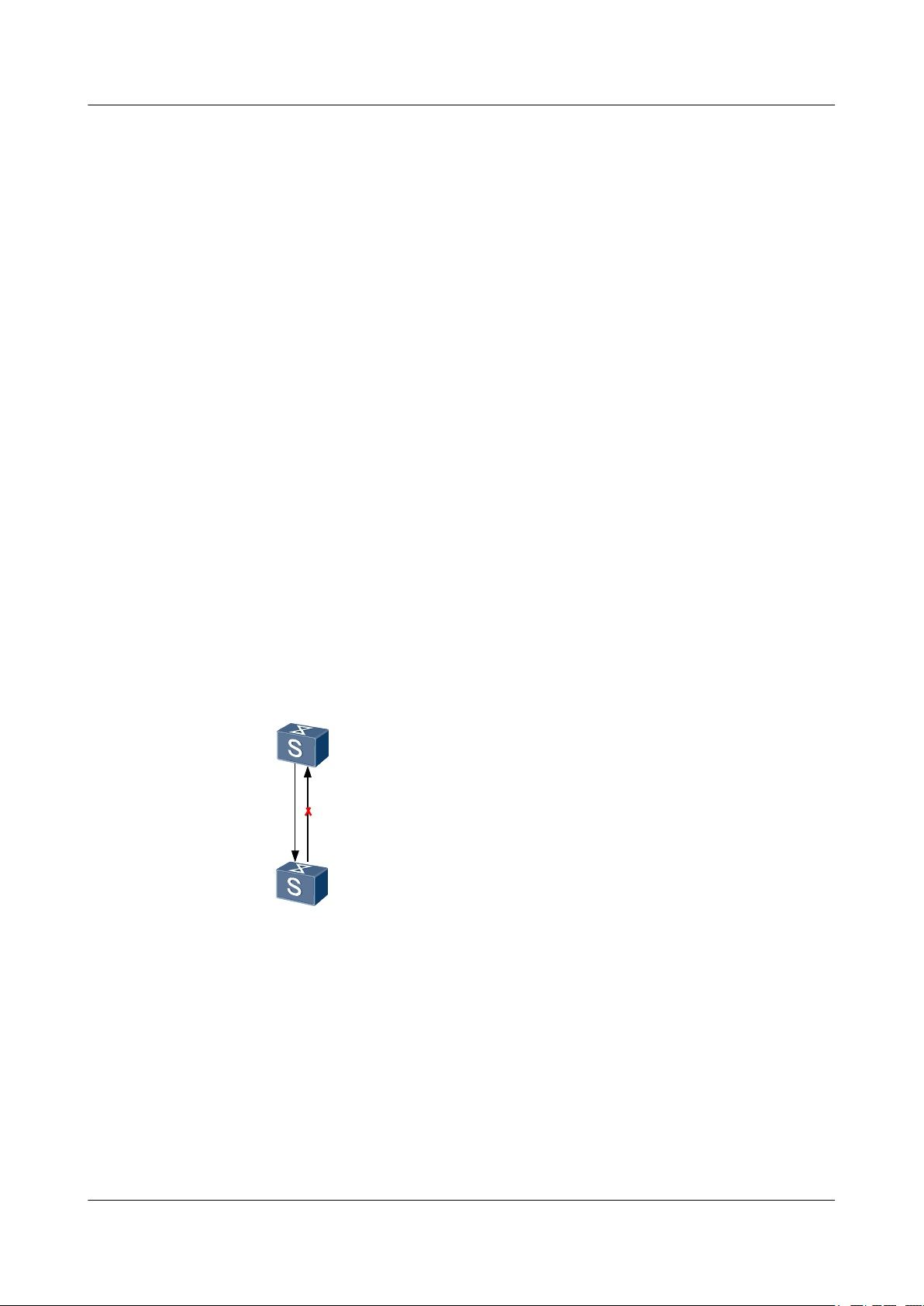
On a network, unidirectional link faults often occur. That is, the local device can receive packets
from the remote device through the link layer, but the remote device cannot receive packets from
the local device.
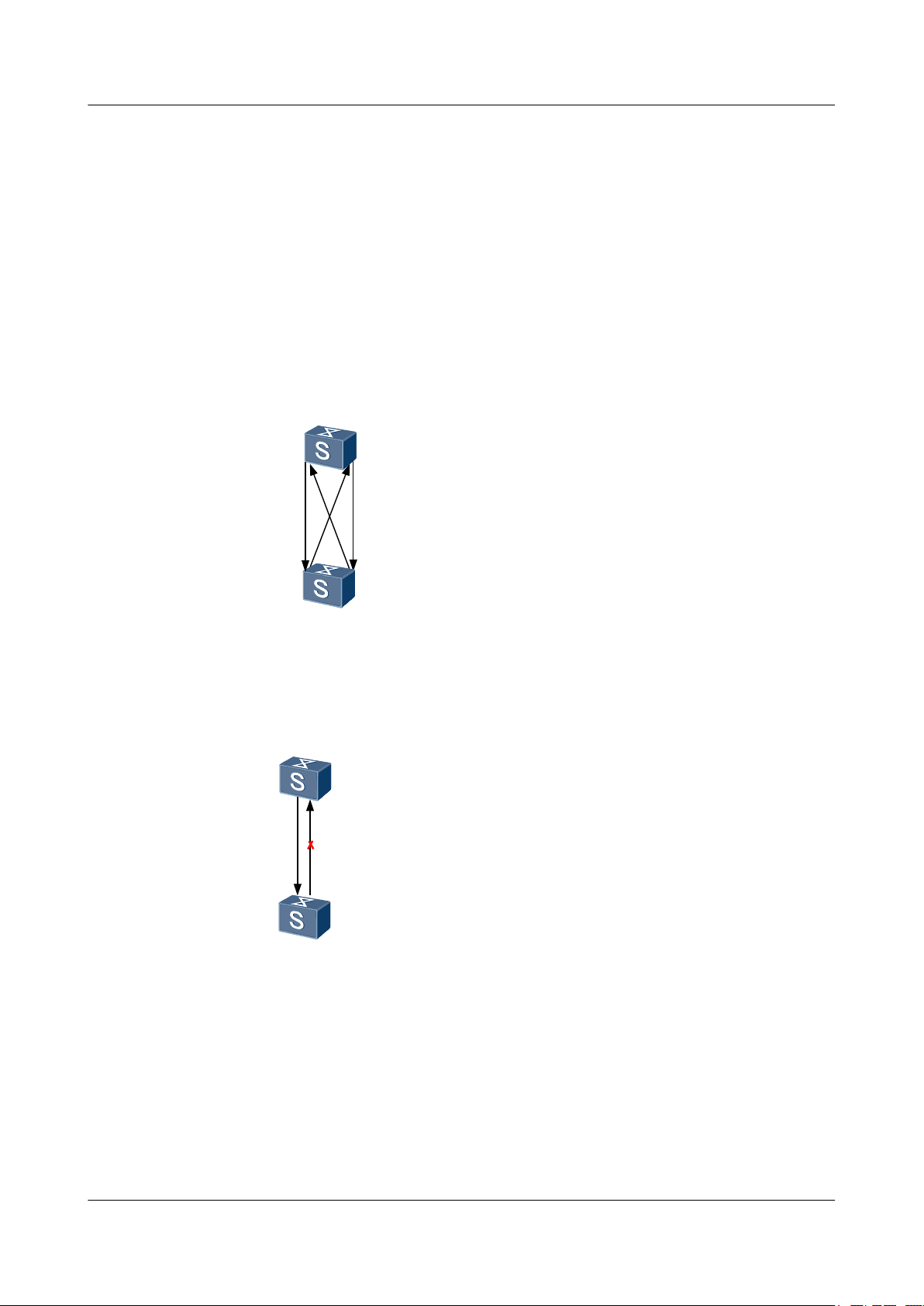
Take the fiber as an example. The fault of unidirectional link may be caused by crossed
connection of fibers or disconnection of one fiber.
Figure 1-1 Crossed connection of fibers
Figure 1-2 Disconnection of one fiber
DLDP can detect the link status of fibers or copper twisted pairs. If a unidirectional link exists,
DLDP automatically disables the interface or prompts the user to manually disable the interface.
This prevents network faults. Currently, the S6700 supports DLDP detection for up to 256
neighbors.
Issue 01 (2011-07-15) Huawei Proprietary and Confidential
As a link layer protocol, DLDP works with the physical layer protocol to detect the link status.
The auto negotiation mechanism on the physical link detects physical signals and faults on the
physical link, and DLDP identifies the remote device and unidirectional link and disables
Copyright © Huawei Technologies Co., Ltd.
2
Page 13
Quidway S6700 Series Ethernet Switches
Configuration Guide - Reliability 1 DLDP Configuration
unreachable interfaces. The auto negotiation mechanism and DLDP work together to detect and
close unidirectional links on the physical and logical interfaces. If the interfaces on both ends
of the link work normally on the physical layer, DLDP checks the connection and packet
exchange between the two interfaces on the link layer. This process cannot be implemented
through the auto negotiation mechanism.
1.2 Configuring DLDP Functions
This section describes how to configure DLDP functions.
1.2.1 Establishing the Configuration Task
Applicable Environment
On a network, unidirectional link faults often occur. To prevent network faults caused by
unidirectional links, you can enable DLDP on interfaces at two ends of a pair of fibers or a copper
twisted pair to monitor the link status. If a unidirectional link exists, DLDP automatically
disables the interface connected to the link or prompts you to manually disable the interface.
Unidirectional links can be tested only when the devices on both ends of the fibers and copper
twisted pairs support DLDP functions.
Pre-configuration Tasks
Before configuring DLDP, complete the following task:
l Configuring the interfaces at both ends to work in non-auto-negotiation mode
Data Preparation
To configure DLDP, you need the following data.
No.
1 Type and number of each interface
2 (Optional)Name of the interface group
3 (Optional) Interval for sending Advertisement packets
4 (Optional) Value of the Delay Down timer
Data
1.2.2 Enabling DLDP
Procedure
Step 1 Run:
system-view
Issue 01 (2011-07-15) Huawei Proprietary and Confidential
Copyright © Huawei Technologies Co., Ltd.
3
Page 14

Quidway S6700 Series Ethernet Switches
Configuration Guide - Reliability 1 DLDP Configuration
The system view is displayed.
Step 2 Run:
dldp enable
DLDP is enabled globally.
Step 3 Run:
interface interface-type interface-number
The Ethernet interface view is displayed.
Or run:
port-group port-group-name
The interface group view is displayed.
Step 4 Run:
dldp enable
DLDP is enabled on the interface.
By default, DLDP is disabled globally and on each interface.
----End
1.2.3 (Optional) Setting the Operating Mode of DLDP
Context
If DLDP works in normal mode, the system can identify only one type of unidirectional link,
that is, the crossed connection of fibers. In this mode, the system does not use any timer, so it
cannot detect that a bidirectional link changes to a unidirectional link.
If DLDP works in enhanced mode, the system can identify two types of unidirectional links,
that is, the crossed connection of fibers and the connection where one fiber is disconnected. To
detect the unidirectional link caused by disconnection of one fiber, you need to manually set the
rate and full-duplex mode of the interconnected ports; otherwise, DLDP does not take effect
even if it is enabled. When a bidirectional link changes to a unidirectional link, the port where
the Tx fiber receives optical signals is in Disable state, and the port where the Tx fiber receives
no optical signals is in Inactive state.
Procedure
Step 1 Run:
system-view
The system view is displayed.
Step 2 Run:
dldp work-mode { enhance | normal }
The operation mode of DLDP is set.
By default, the operation mode of DLDP is enhance mode.
----End
Issue 01 (2011-07-15) Huawei Proprietary and Confidential
Copyright © Huawei Technologies Co., Ltd.
4
Page 15

Quidway S6700 Series Ethernet Switches
Configuration Guide - Reliability 1 DLDP Configuration
1.2.4 (Optional) Enabling DLDP Compatible Mode
Context
If the S6700 needs to work with the following Huawei switches to provide the DLDP function,
this task is required. The software versions of the following switches must support the DLDP
function:
l S8500
l S7800
l S6500
l S5600
l S5100–EI
l S3900
l S3500
l S3100
Procedure
Step 1 Run:
Step 2 Run:
Step 3 Run:
system-view
The system view is displayed.
bpdu mac-address mac-address [ mac-address-mask ]
The S6700 is configured to use the BPDU MAC address 010F-E200-0001 to send DLDP packets.
The MAC addresses used for sending DLDP packets on the S6700 and on the old Huawei
switches are different. Therefore, the S6700 must be configured to use BPDU MAC address
10F-E200-0001 to send DLDP packets.
interface interface-type interface-number
The interface view is displayed.
Or run:
port-group port-group-name
The port group view is displayed.
Step 4 Run:
dldp compatible-mode enable
The DLDP compatible mode is enabled.
If two devices are connected by using two links, the DLDP compatible mode must be enabled
or disabled on both the two interfaces.
If devices at both ends are S6700s, the interfaces at both ends must use the same DLDP
compatible mode. That is, you must enable or disable the DLDP compatible mode
simultaneously on the interfaces.
Issue 01 (2011-07-15) Huawei Proprietary and Confidential
Copyright © Huawei Technologies Co., Ltd.
5
Page 16

Quidway S6700 Series Ethernet Switches
Configuration Guide - Reliability 1 DLDP Configuration
Step 5 Run:
dldp compatible-mode local-mac
The DLDP packets sent in the DLDP compatible mode contain MAC addresses.
After the DLDP compatible mode is enabled on the S6700, the peer device of the S6700 may
discover multiple neighbors, causing DLDP flapping. The dldp compatible-mode local-mac
command can prevent this problem.
NOTE
At least one bit in the MAC address must be 0, and the MAC address cannot be a multicast MAC address.
----End
1.2.5 (Optional) Setting the Interval for Sending Advertisement Packets
Context
Procedure
Step 1 Run:
Step 2 Run:
Do as follows on the S6700 that needs to run DLDP.
system-view
The system view is displayed.
dldp interval time
The interval for sending Advertisement packets is set.
By default, the interval for sending Advertisement packets is 5 seconds.
The interval for sending Advertisement packets must be smaller than one third of the STP
convergence time. If the interval is too long, STP loops occur before a unidirectional link is shut
down on a DLDP interface. If the interval is too short, traffic on the network increases.
NOTE
Ensure that the interval for sending Advertisement packets is the same on the local and remote devices that
are connected through fibers or copper twisted pairs.
----End
1.2.6 (Optional) Setting the Delay Down Timer
Procedure
Step 1 Run:
system-view
The system view is displayed.
Issue 01 (2011-07-15) Huawei Proprietary and Confidential
Copyright © Huawei Technologies Co., Ltd.
6
Page 17

Quidway S6700 Series Ethernet Switches
Configuration Guide - Reliability 1 DLDP Configuration
Step 2 Run:
dldp delaydown-timer time
The Delay Down timer is set.
By default, the Delay Down timer is 1 second.
If DLDP receives a Port-Down event when it is in Active, Advertisement, or Probe state, DLDP
will enter Inactive state and clear the neighbor information. In certain cases, the port is Down
for a very short time. For example, failure of the Tx fiber on a port may cause jitter of optical
signals on the Rx fiber, that is, the port becomes Down and then becomes Up again. To prevent
the neighbor information from being deleted immediately in this case, DLDP first enters the
DelayDown state and starts the DelayDown timer. Before the DelayDown timer times out, DLDP
retains the neighbor information and responds to only Port-Up events.
l If DLDP does not receive any Port-Up event when the DelayDown timer times out, it deletes
the neighbor information and enters the Inactive state.
l If DLDP receives the Port-Up event before the DelayDown timer times out, it returns to the
previous state.
The Delay Down timer applies to all DLDP interfaces.
----End
1.2.7 (Optional) Setting the Interface Blocking Mode
Context
When a unidirectional link is detected, DLDP blocks the corresponding interface in either of the
following ways:
l Manual mode: This mode can prevent DLDP from blocking the interface immediately to
affect packet forwarding when the network performance is poor. It is a compromise mode
used to prevent an interface from being blocked because of incorrect judgment of the
system. In this mode, DLDP detects the unidirectional link, and the network administrator
blocks the interface manually. When the DLDP state machine detects a unidirectional link,
the system records the log and sends trap messages to prompt you the network administrator
to block the interface manually. Then the DLDP state machine changes to the Disable state.
l Automatic mode: It is the default mode. When a unidirectional link is detected, the DLDP
state machine changes to the Disable state, and the system records the log, sends trap
messages, and sets the interface state to Blocking.
Procedure
Step 1 Run:
system-view
The system view is displayed.
Step 2 Run:
dldp unidirectional-shutdown { auto | manual }
The mode of blocking interfaces when a unidirectional link fault is detected is set.
By default, DLDP automatically blocks the interface when a unidirectional link fault is detected.
Issue 01 (2011-07-15) Huawei Proprietary and Confidential
Copyright © Huawei Technologies Co., Ltd.
7
Page 18

Quidway S6700 Series Ethernet Switches
Configuration Guide - Reliability 1 DLDP Configuration
An interface in DLDP Down state still sends RecoverProbe packets periodically. If correct
RecoverEcho packets are received, it indicates that the unidirectional link changes to the
bidirectional link and the DLDP status becomes Up.
----End
1.2.8 (Optional) Setting the Authentication Mode of DLDP Packets
Procedure
Step 1 Run:
system-view
The system view is displayed.
Step 2 Run:
dldp authentication-mode { md5 md5-password | none | simple simple-password }
The DLDP authentication mode used between the interfaces of the S6700 and the remote device
is set.
By default, the DLDP authentication mode used between the interfaces of the S6700 and the
remote device is none. That is, DLDP packets are not authenticated.
NOTE
Ensure that the local and remote devices use the same authentication mode and same authentication
password; otherwise, the DLDP authentication fails. DLDP works normally only after the DLDP
authentication succeeds.
----End
1.2.9 Checking the Configuration
Procedure
Step 1 Run the display dldp [ interface interface-type interface-number ] command to check the DLDP
configuration and neighbor entries.
----End
Example
Run the display dldp command, and you can view the operation mode of DLDP, interval for
sending Advertisement packets, value of the Delay Down timer, interface disabling mode, and
authentication mode of DLDP packets.
<Quidway> display dldp
DLDP global status : enable
DLDP interval : 5s
DLDP work-mode : enhance
DLDP authentication-mode : simple, password is 123
DLDP unidirectional-shutdown : auto
DLDP delaydown-timer : 2s
The number of enabled ports is 2.
The number of global neighbors is: 2.
Interface XGigabitEthernet0/0/1
Issue 01 (2011-07-15) Huawei Proprietary and Confidential
Copyright © Huawei Technologies Co., Ltd.
8
Page 19

Quidway S6700 Series Ethernet Switches
Configuration Guide - Reliability 1 DLDP Configuration
DLDP port state : advertisement
DLDP link state : up
The neighbor number of the port is 1.
Neighbor mac address : 0000-0000-0100
Neighbor port index : 21
Neighbor state : two way
Neighbor aged time : 13
Interface XGigabitEthernet0/0/2
DLDP port state : advertisement
DLDP link state : up
The neighbor number of the port is 1.
Neighbor mac address : 0000-0000-1100
Neighbor port index : 22
Neighbor state : two way
Neighbor aged time : 12
1.3 Resetting the DLDP Status
This section describes how to reset the DLDP status.
1.3.1 Establishing the Configuration Task
Applicable Environment
When a unidirectional link is detected, the corresponding interface enters the Disable state. The
system prompts you to disable the interface or sets the interface state to DLDP Down
automatically according to the configuration. To enable the interface to detect unidirectional
links again, you can reset the DLDP state of the interface. The DLDP status of the interface after
recovery depends on the physical status of the interface. If the physical status is Down, the DLDP
status of the interface changes to Inactive. If the physical status is Up, the DLDP status changes
to Active.
Pre-configuration Tasks
None.
Data Preparation
To reset the DLDP status, you need the following data.
No.
1 Type and number of each interface
2 Name of the interface group
Data
1.3.2 Resetting the DLDP Status Globally
Context
The dldp reset command takes effect only when DLDP is enabled globally and on interfaces.
Issue 01 (2011-07-15) Huawei Proprietary and Confidential
Copyright © Huawei Technologies Co., Ltd.
9
Page 20

Quidway S6700 Series Ethernet Switches
Configuration Guide - Reliability 1 DLDP Configuration
When you reset the DLDP status globally, the DLDP status is reset for all the disabled interfaces
on the S6700.
Procedure
Step 1 Run:
system-view
The system view is displayed.
Step 2 Run:
dldp reset
The DLDP status is reset globally.
----End
1.3.3 Resetting the DLDP Status of an Interface
Context
Procedure
Step 1 Run:
Step 2 Run:
If you reset the DLDP status on an interface or interface group, the DLDP status is reset for the
interface or all the disabled interfaces in the interface group.
The dldp reset command takes effect only when DLDP is enabled globally and on interfaces.
system-view
The system view is displayed.
interface interface-type interface-number
The Ethernet interface view is displayed.
Or run:
port-group port-group-name
The interface group view is displayed.
Step 3 Run:
dldp reset
The DLDP status is reset on the interface or interface group.
----End
1.3.4 Checking the Configuration
Issue 01 (2011-07-15) Huawei Proprietary and Confidential
Copyright © Huawei Technologies Co., Ltd.
10
Page 21

Quidway S6700 Series Ethernet Switches
Configuration Guide - Reliability 1 DLDP Configuration
Procedure
Step 1 Run the display dldp [ interface interface-type interface-number ] command to check the DLDP
configuration and neighbor entries.
----End
Example
Run the display dldp command, and you can view the status of an interface after the DLDP
status is reset.
<Quidway> display dldp
DLDP global status : enable
DLDP interval : 5s
DLDP work-mode : enhance
DLDP authentication-mode : simple, password is 123
DLDP unidirectional-shutdown : auto
DLDP delaydown-timer : 2s
The number of enabled ports is 2.
The number of global neighbors is: 2.
Interface XGigabitEthernet0/0/1
DLDP port state : advertisement
DLDP link state : up
The neighbor number of the port is 1.
Neighbor mac address : 0000-0000-0100
Neighbor port index : 21
Neighbor state : two way
Neighbor aged time : 13
Interface XGigabitEthernet0/0/2
DLDP port state : advertisement
DLDP link state : up
The neighbor number of the port is 1.
Neighbor mac address : 0000-0000-1100
Neighbor port index : 22
Neighbor state : two way
Neighbor aged time : 12
1.4 Maintaining DLDP
This section describes how to maintain DLDP.
1.4.1 Clearing the Statistics of DLDP
Context
CAUTION
Statistics of DLDP cannot be restored after you clear them. So, confirm the action before you
use the command.
Issue 01 (2011-07-15) Huawei Proprietary and Confidential
Copyright © Huawei Technologies Co., Ltd.
11
Page 22
SwitchB
XGE0/0/1
XGE0/0/1
SwitchA
RX
TX
RX
TX
Quidway S6700 Series Ethernet Switches
Configuration Guide - Reliability 1 DLDP Configuration
Procedure
Step 1 Run the reset dldp statistics [ interface interface-type interface-number ] command in the user
view to clear the statistics of DLDP packets on an interface.
----End
1.5 Configuration Examples
This section provides a configuration example of DLDP.
1.5.1 Example for Configuring DLDP
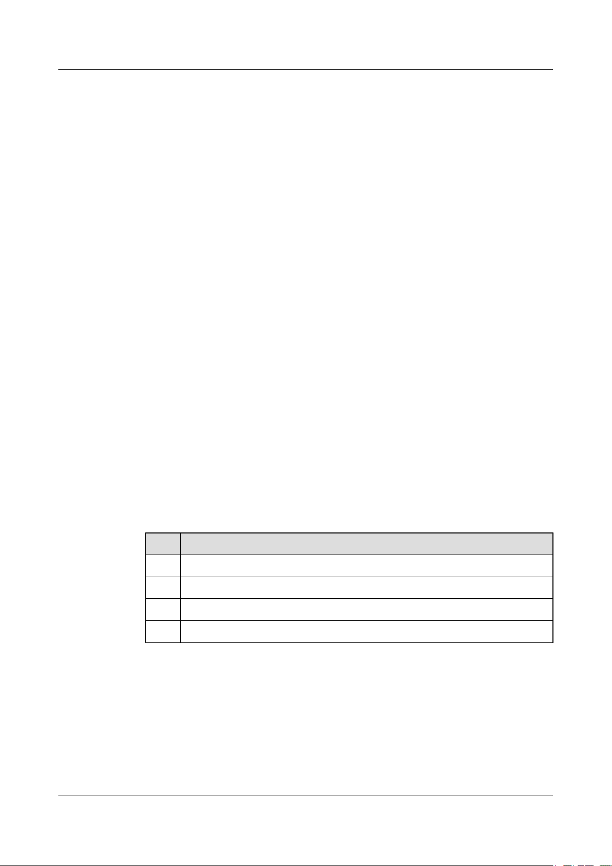
Networking Requirements
As shown in Figure 1-3, two S6700s are connected through a pair of optical fibers. On a fiber,
RX indicate the receive end, and TX indicates the transmit end. DLDP is enabled on the
interconnected interfaces. If the Rx fiber on Switch A fails, Switch A cannot receive optical
signals. In this case, XGE 0/0/1 of Switch A becomes Down and cannot send or receive any
packets. However, the Tx fiber on Switch B still sends optical signals, and Switch B can receive
optical signals because the Tx fiber on Switch A is working normally. Therefore, the link status
on Switch B is still Up. If Switch B does not receive any DLDP packet from Switch A within
the neighbor aging time, XGE 0/0/1 of Switch B changes to unidirectional state. To prevent
network faults, DLDP disables XGE 0/0/1 of Switch B.
Figure 1-3 Disconnection of one fiber
Configuration Roadmap
The configuration roadmap is as follows:
1. Configure the interfaces at both ends to work in non-auto-negotiation mode.
2. Enable DLDP.
3. Set the operation mode of DLDP.
4. Set the interval for sending Advertisement packets.
Issue 01 (2011-07-15) Huawei Proprietary and Confidential
Copyright © Huawei Technologies Co., Ltd.
12
Page 23

Quidway S6700 Series Ethernet Switches
Configuration Guide - Reliability 1 DLDP Configuration
5. Set the Delay Down timer.
6. Set the mode of disabling the interface when a unidirectional link is detected.
7. Set the authentication mode of DLDP packets.
Data Preparation
To complete the configuration, you need the following data:
l Type and number of each interface
l Interval for sending Advertisement packets
l Value of the Delay Down timer
Procedure
Step 1 Configure the interface on Switch A to work in non-auto negotiation mode.
<Quidway> system-view
[Quidway] sysname SwitchA
[SwitchA] interface xgigabitethernet 0/0/1
[SwitchA-XGigabitEthernet0/0/1] undo negotiation auto
[SwitchA-XGigabitEthernet0/0/1] quit
Step 2 Enable DLDP globally
[SwitchA] dldp enable
Step 3 Enable DLDP on the interface.
[SwitchA] interface xgigabitethernet 0/0/1
[SwitchA-XGigabitEthernet0/0/1] dldp enable
[SwitchA-XGigabitEthernet0/0/1] quit
Step 4 Configure DLDP to work in enhanced mode.
[SwitchA] dldp work-mode enhance
Step 5 Set the interval for sending Advertisement packets to 80 seconds.
[SwitchA] dldp interval 80
Step 6 Set the timeout interval of the DelayDown timer to 4 seconds.
[SwitchA] dldp delaydown-timer 4
Step 7 Configure DLDP to automatically shut down the interface where a unidirectional link is detected.
[SwitchA] dldp unidirectional-shutdown auto
Step 8 Set the authentication mode of DLDP packets to simple password authentication and set the
password to 123456.
[SwitchA] dldp authentication-mode simple 12345
Repeat the preceding steps on Switch B.
Step 9 Verify the configuration.
After the configuration, run the display dldp command in the interface view, and you can find
that the DLDP status of the interface is advertisement.
[SwitchA] display dldp interface xgigabitethernet 0/0/1
Interface XGigabitEthernet0/0/1
DLDP port state: advertisement
DLDP link state: up
The neighbor number of the port is: 1.
Neighbor mac address:0018-2000-0083
Issue 01 (2011-07-15) Huawei Proprietary and Confidential
Copyright © Huawei Technologies Co., Ltd.
13
Page 24

Quidway S6700 Series Ethernet Switches
Configuration Guide - Reliability 1 DLDP Configuration
Neighbor port index:27
Neighbor state:two way
Neighbor aged time:185
Remove the Rx fiber from Switch A to simulate a unidirectional link between XGE 0/0/1 of
Switch A and XGE 0/0/1 of Switch B, as shown in Figure 1-3. You find that DLDP blocks the
XGE 0/0/1 interface of Switch B.
# Run the display dldp on Switch A, and you can find that the DLDP status of XGE 0/0/1 is
inactive. Run the display dldp on Switch B, and you can find that the DLDP status of XGE
0/0/1 is disable.
[SwitchA] display dldp interface xgigabitethernet 0/0/1
Interface XGigabitEthernet0/0/1
DLDP port state: inactive
DLDP link state: down
The neighbor number of the port is: 0
[SwitchB] display dldp interface xgigabitethernet 0/0/1
Interface XGigabitEthernet0/0/1
DLDP port state: disable
DLDP link state: up
The neighbor number of the port is: 0
----End
Configuration Files
l Configuration file of Switch A
#
sysname SwitchA
#
dldp enable
dldp interval 80
dldp delaydown-timer 4
dldp authentication-mode simple 12345
#
interface XGigabitEthernet0/0/1
dldp enable
undo negotiation auto
#
return
l Configuration file of Switch B
#
sysname SwitchB
#
dldp enable
dldp interval 80
dldp delaydown-timer 4
dldp authentication-mode simple 12345
#
interface XGigabitEthernet0/0/1
dldp enable
undo negotiation auto
#
return
Issue 01 (2011-07-15) Huawei Proprietary and Confidential
Copyright © Huawei Technologies Co., Ltd.
14
Page 25

Quidway S6700 Series Ethernet Switches
Configuration Guide - Reliability 2 Smart Link and Monitor Link Configuration
2 Smart Link and Monitor Link Configuration
About This Chapter
This chapter describes the principle, configuration procedure, and configuration example of the
Smart Link and Monitor Link.
2.1 Smart Link and Monitor Link
This section describes the concepts of Smart Link and Monitor Link.
2.2 Configuring a Smart Link Group
This section describes how to create a Smart Link group, enable the Smart Link group, configure
the master and slave interfaces, enable the revertive switching, and configure functions related
to Flush packets.
2.3 Configuring a Flow Control Policy in a Smart Link Group
This section describes how to configure the advanced functions of the Smart Link group, such
as lock of data flows and manual switchover between links.
2.4 Configuring a Monitor Link Group
This section describes how to create a Monitor Link group, configure the uplink and downlink
interfaces, and enable the revertive switching.
2.5 Maintaining the Smart Link
This section describes how to debug the Smart Link.
2.6 Configuration Examples
This section provides several configuration examples of the Smart Link.
Issue 01 (2011-07-15) Huawei Proprietary and Confidential
Copyright © Huawei Technologies Co., Ltd.
15
Page 26

Quidway S6700 Series Ethernet Switches
Configuration Guide - Reliability 2 Smart Link and Monitor Link Configuration
2.1 Smart Link and Monitor Link
This section describes the concepts of Smart Link and Monitor Link.
The dual-homing networking is often used. In this networking, STP blocks redundant links,
providing redundancy. When the active link fails, the traffic is switched to the standby link.
Although this scheme can implement redundancy, the performance cannot meet the requirements
of users. Route convergence is performed within several seconds even if the Rapid Spanning
Tree Protocol (RSTP) is used. The convergence speed is unfavorable for the high-end Ethernet
switch used on the core of the carrier-class network.
To address the preceding problem, Huawei introduces Smart Link in dual-homing networking
to implement redundancy of active and standby links and fast transition. In this manner, the high
performance is ensured and the configuration is simplified. In addition, cooperation of interfaces
is used.
The Monitor Link is introduced as a supplement to the Smart Link. This technology supports
the association of interfaces. A Monitor Link group consists of an uplink interface and several
downlink interfaces. If the uplink interface fails, the Monitor Link group automatically disables
the downlink interfaces. When the uplink interface recovers, the downlink interfaces also
recover.
2.2 Configuring a Smart Link Group
This section describes how to create a Smart Link group, enable the Smart Link group, configure
the master and slave interfaces, enable the revertive switching, and configure functions related
to Flush packets.
2.2.1 Establishing the Configuration Task
Applicable Environment
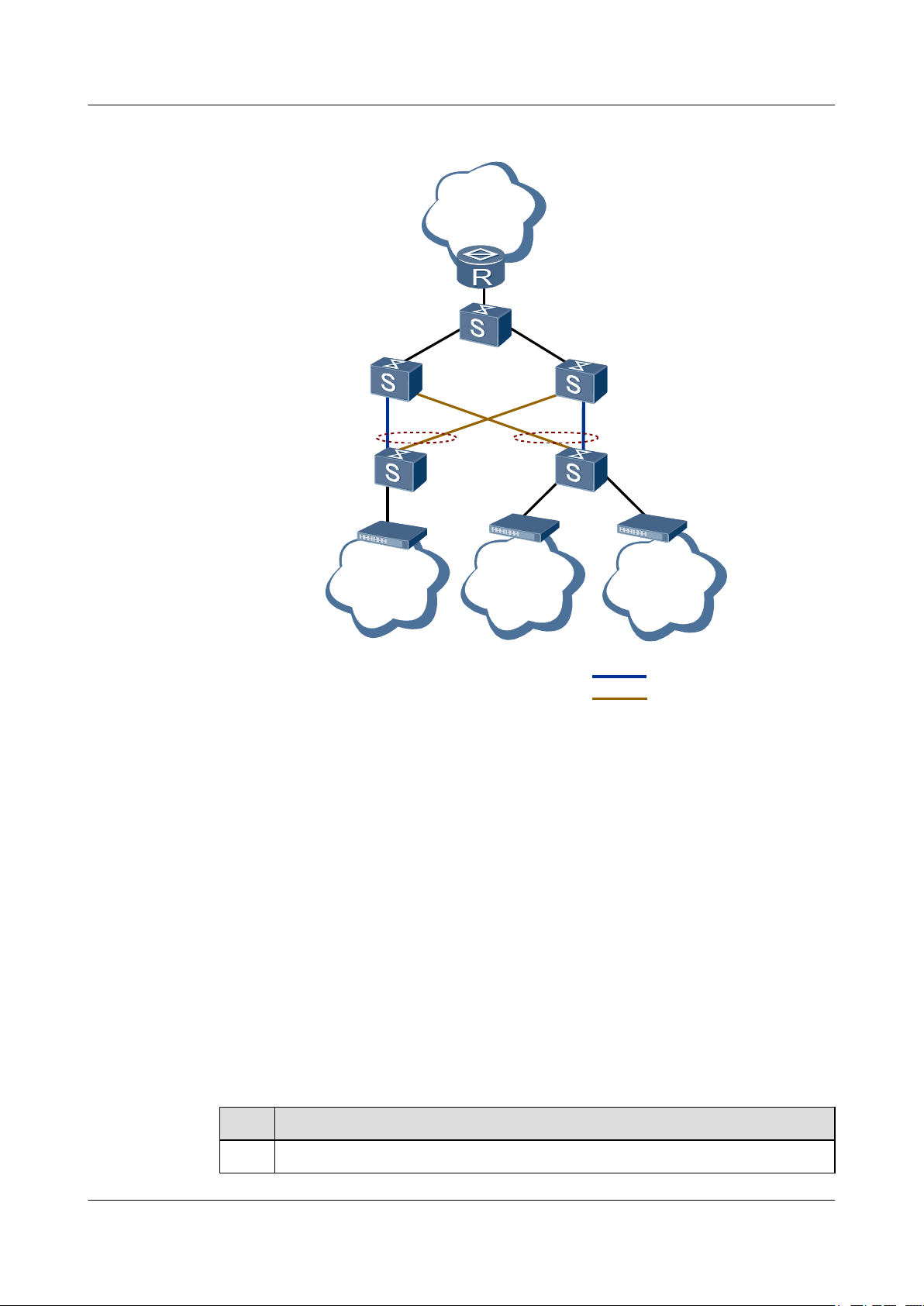
As shown in Figure 2-1, each device at the access and convergence layer is connected to two
uplink devices. This networking mode provides higher security and reduces the duration of
service interruption caused by the link failure.
Issue 01 (2011-07-15) Huawei Proprietary and Confidential
Copyright © Huawei Technologies Co., Ltd.
16
Page 27
SwitchD
SwitchB
SwitchA
SwitchC
IP/MPLS
core
network
Smart Link group
Smart Link group
SwitchE
User
1
Active link
Inactive link
User
3
User
2
Quidway S6700 Series Ethernet Switches
Configuration Guide - Reliability 2 Smart Link and Monitor Link Configuration
Figure 2-1 Application scenario of the Smart Link
Pre-configuration Tasks
Data Preparation
As shown in Figure 2-1, Switch D and Switch E are connected to user devices, and both are
connected to Switch B and Switch C. Configure the Smart Link on Switch D and Switch E and
add the two uplink interfaces to the respective Smart Link group to avoid loops. In this manner,
interrupted services can be restored in milliseconds.
Before configuring the basic functions of a Smart Link group, complete the following task:
l Ensuring that the Multiple Spanning Tree Protocol (MSTP), Rapid Ring Protection
Protocol (RRPP), and Smart Ethernet Protection (SEP) are not enabled on the master and
slave interfaces of the Smart Link group
To configure basic functions of the Smart Link group, you need the following data.
No.
Data
1 Number of the interface added to the Smart Link group
Issue 01 (2011-07-15) Huawei Proprietary and Confidential
Copyright © Huawei Technologies Co., Ltd.
17
Page 28

Quidway S6700 Series Ethernet Switches
Configuration Guide - Reliability 2 Smart Link and Monitor Link Configuration
No. Data
2 ID of the Smart Link group
3 IDs of VLANs bound to the instance
4 Control VLAN ID contained in the Flush packet
5 (Optional) Password contained in the Flush packet
2.2.2 Creating and Enabling a Smart Link Group
Context
Do as follows on the S6700.
Procedure
Step 1 Run:
system-view
The system view is displayed.
Step 2 Run:
smart-link group group-id
A Smart Link group is created and the Smart Link group view is displayed.
The S6700 supports a maximum of 16 Smart Link groups.
Step 3 (Optional)Run:
protected-vlan reference-instance { instance-id1 [ to instance-id2 ] }&<1-10>
An instance is bound to the Smart Link group as the protected instance. The functions of the
Smart link group take effect only on the VLANs bound to the protected instance. For details
about STP instance configuration, see Configuring and Activating an MST Region.
NOTE
By default, a Smart Link group protects all VLANs and the protected-vlan reference-instance command
is applicable only to multicast services.
----End
2.2.3 Configuring the Master and Slave Interfaces in a Smart Link Group
Context
The slave interface of a Smart Link group is blocked when the group is started.
An interface cannot be added to a Smart Link group in the following situations:
l The interface is a Rapid Ring Protection Protocol (RRPP) interface.
Issue 01 (2011-07-15) Huawei Proprietary and Confidential
Copyright © Huawei Technologies Co., Ltd.
18
Page 29

Quidway S6700 Series Ethernet Switches
Configuration Guide - Reliability 2 Smart Link and Monitor Link Configuration
l Spanning Tree Protocol (STP) is enabled on the interface.
l The interface has been added to an Eth-Trunk.
l The interface has been added to a Monitor Link group.
l The interface has been added to another Smart Link group.
l STP is configured on the interface.
Procedure
Step 1 Run:
system-view
The system view is displayed.
Step 2 Run:
interface interface-type interface-number
The system view is displayed.
Step 3 Run:
stp disable
STP is disabled on the interface.
Step 4 Run:
quit
Return to the interface view.
Step 5 Run:
smart-link group group-id
The Smart Link group view is displayed.
Step 6 Run:
port interface-type interface-number master
An interface is added to the Smart Link group and is specified as the master interface.
Step 7 Run:
port interface-type interface-number slave
Another interface is added to the Smart Link group and is specified as the slave interface.
A Smart Link group consists of a master interface and a slave interface. By default, a Smart Link
group does not have interfaces.
----End
2.2.4 Enabling the Sending of Flush Packets
Context
When the active and standby links of the Smart Link group switch, the existing forwarding
entries no longer apply to the new topology. All the MAC address entries and ARP entries on
the network need to be updated. Then the Smart Link group sends Flush packets to ask other
devices to update the MAC address table and ARP entries.
Issue 01 (2011-07-15) Huawei Proprietary and Confidential
Copyright © Huawei Technologies Co., Ltd.
19
Page 30

Quidway S6700 Series Ethernet Switches
Configuration Guide - Reliability 2 Smart Link and Monitor Link Configuration
Because manufacturers define the format of Flush packets differently, the Flush packets
described here are used only for the intercommunication between Huawei S-series switches. In
addition, the function of receiving Flush packets must be enabled on the remote switch.
If you run flush send control-vlan vlan-id [ password simple password ] command in the Smart
Link group view, the Smart Link group is enabled to send Flush packets that contain the specified
control VLAN ID and password. The VLAN ID specified by vlan-id must already exist on the
S6700. If the specified VLAN ID does not exist on the S6700, Flush packets cannot be sent.
Do as follows on the S6700.
Procedure
Step 1 Run:
system-view
The system view is displayed.
Step 2 Run:
smart-link group group-id
The Smart Link group view is displayed.
Step 3 Run:
flush send control-vlan vlan-id [ password simple password ]
The S6700 is enabled to send Flush packets, and the control VLAN ID and password contained
in Flush packets are set.
A control VLAN cannot be a VLAN mapping a load-balancing instance.
The control VLAN ID and password contained in Flush packets on both devices must be the
same. That is, the control VLAN ID and password in Flush packets sent by the device must be
the same as the control VLAN ID and password in Flush packets received by the device.
NOTE
After the flush send control-vlan command is run, the interface cannot be added to the control VLAN. You need
to configure the interface to allow the packets of the control VLAN to pass through.
----End
2.2.5 (Optional) Configuring Load Balancing in a Smart Link Group
Context
Do as follows on the S6700.
Procedure
Step 1 Run:
system-view
The system view is displayed.
Step 2 Run:
stp region-configuration
Issue 01 (2011-07-15) Huawei Proprietary and Confidential
Copyright © Huawei Technologies Co., Ltd.
20
Page 31

Quidway S6700 Series Ethernet Switches
Configuration Guide - Reliability 2 Smart Link and Monitor Link Configuration
The Multiple Spanning Tree (MST) region view is displayed.
Step 3 Run:
instance instance-id vlan { vlan-id1 [ to vlan-id2 ] }&<1-10>
The mapping between an instance and VLANs is set.
A domain supports up to 49 instances, among which Instance 0 is the default instance and does
not need to be created.
By default, all VLANs are mapped to instance 0.
Step 4 Run:
active region-configuration
The configuration of the MST region is activated.
After configuring the domain name, VLAN mapping table, or MSTP revision level, you must
run the active region-configuration command for the configuration to take effect.
Step 5 Run:
quit
Return to the system view.
Step 6 Run:
smart-link group group-id
The Smart Link group view is displayed.
Step 7 Run:
load-balance instance { instance-id1 [ to instance-id2 ] } &<1-10> slave
Packets of the VLANs bound to the specified instance are sent from the slave interface to
implement load balancing.
----End
2.2.6 (Optional) Enabling Revertive Switching and Setting the WTR Time
Context
When the active link in a Smart Link group fails, the traffic is automatically switched to the
standby link. The original active link does not preempt the traffic but remains blocked after
recovering from the fault. To switch the traffic back to the active link, you can adopt either of
the following methods:
l Enable the revertive switching of a Smart Link group. The switching is automatically
performed after the revertive switching timer times out.
l Run the smart-link manual switch command to perform the link switching forcibly.
NOTE
The link switching is performed only when the two member interfaces in a group are both Up.
Do as follows on the S6700.
Issue 01 (2011-07-15) Huawei Proprietary and Confidential
Copyright © Huawei Technologies Co., Ltd.
21
Page 32

Quidway S6700 Series Ethernet Switches
Configuration Guide - Reliability 2 Smart Link and Monitor Link Configuration
Procedure
Step 1 Run:
system-view
The system view is displayed.
Step 2 Run:
smart-link group group-id
The Smart Link group view is displayed.
Step 3 Run:
restore enable
Revertive switching is enabled for the Smart Link group.
By default, the revertive switching of the Smart Link group is disabled.
Step 4 (Optional) Run:
timer wtr wtr-time
The wait to recover (WTR) time of the Smart Link group is set.
By default, the WTR time of a Smart Link group is 60 seconds.
----End
2.2.7 (Optional) Enabling the Receiving of Flush Packets
Context
An interface receives Flush packets only when it is configured with the control VLAN ID and
added to this VLAN.
Do as follows on SwitchA, SwitchB, and SwitchC shown in Figure 2-1.
Procedure
Step 1 Run:
system-view
The system view is displayed.
Step 2 Run:
interface interface-type interface-number
The view of the downlink interface of the SwitchA, SwitchB, or SwitchC is displayed.
Step 3 Run:
smart-link flush receive control-vlan vlan-id [ password simple password ]
The interface is enabled to receive Flush packets, and the control VLAN ID and password
contained in Flush packets are set.
The password is optional. If no password is specified, no password is used for authentication.
When the control VLAN ID is changed, the password must also be changed.
Issue 01 (2011-07-15) Huawei Proprietary and Confidential
Copyright © Huawei Technologies Co., Ltd.
22
Page 33

Quidway S6700 Series Ethernet Switches
Configuration Guide - Reliability 2 Smart Link and Monitor Link Configuration
The control VLAN ID and password contained in Flush packets on both devices must be the
same. That is, the control VLAN ID and password in Flush packets sent by the device must be
the same as the control VLAN ID and password in Flush packets received by the device.
----End
2.2.8 (Optional) Setting the Holdtime of the Smart Link Switchover
Context
If the Smart Link switchover is performed because of temporary interruption, packet forwarding
and system performance are affected. To address this problem, you can set the holdtime of the
Smart Link switchover. If the interface of the Smart Link group repeatedly alternates between
Up and Down states, the status of the Smart Link group is not immediately changed, but is
changed according to the Up or Down status obtained by an interface of the Smart Link group
until the holdtime expires. In this manner, Smart Link switchover caused by link interruption is
suppressed.
Procedure
Step 1 Run:
system-view
The system view is displayed.
Step 2 Run:
smart-link group group-id
The Smart Link group view is displayed.
Step 3 Run:
smart-link hold-time hold-time
The holdtime of the Smart Link switchover is set.
----End
2.2.9 Enabling the Functions of the Smart Link Group
Context
After the functions of the Smart Link group are enabled, the standby interface in the group is
blocked. After the functions of the Smart Link group are disabled, the blocked standby interface
is recovered.
Procedure
Step 1 Run:
system-view
The system view is displayed.
Step 2 Run:
smart-link group group-id
Issue 01 (2011-07-15) Huawei Proprietary and Confidential
Copyright © Huawei Technologies Co., Ltd.
23
Page 34

Quidway S6700 Series Ethernet Switches
Configuration Guide - Reliability 2 Smart Link and Monitor Link Configuration
The Smart Link group view is displayed.
Step 3 Run:
smart-link enable
The functions of the Smart Link group are enabled.
----End
2.2.10 Checking the Configuration
Procedure
l Run the display smart-link group { all | group-id } command to check information about
a Smart Link group.
l Run the display smart-link flush command to check information about the received Flush
packets.
----End
Example
Run the display smart-link group { all | group-id } command to check information about a
Smart Link group. The following information is displayed:
<Quidway> display smart-link group 1
Smart Link group 1 information :
Smart Link group was enabled
Wtr-time is: 30 sec.
Load-Balance Instance: 1 to 2
There is no protected-vlan reference-instance
DeviceID: 0018-2000-0083 Control-vlan ID: 20
Member Role State Flush Count Last-Flush-Time
----------------------------------------------------------------------- XGigabitEthernet0/0/1 Master Active 1 2008/11/21 16:37:20 UTC
+05:00
XGigabitEthernet0/0/2 Slave Inactive 2 2008/11/21 17:45:20 UTC
+05:00
If the configuration is correct, the following information is displayed:
l The functions of the Smart Link group are enabled. Therefore, "Smart link group was
enabled" is displayed.
l The status of the interfaces in the Smart Link group is displayed, including the role of each
interface in the group, number of sent Flush packets, and time when the last Flush packets
are sent. As shown in the preceding information, XGE 0/0/1 is the master interface in the
Smart Link group; this interface is in the Forwarding state; it sent a Flush packet at 16:37
on 2008-11-21.
l The control VLAN ID contained in the sent Flush packets is 20.
Run the display smart-link flush command, and you can view information about received Flush
packets.
<Quidway> display smart-link flush
Receive flush packets count: 1191
Receive last flush interface: XGigabitEthernet0/0/1
Receive last flush packet time: 16:48:53 UTC+05:00
2009/02/23
Receive last flush packet source mac: 0018-0202-0088
Receive last flush packet control vlan ID: 20
Issue 01 (2011-07-15) Huawei Proprietary and Confidential
Copyright © Huawei Technologies Co., Ltd.
24
Page 35

SwitchA
SwitchE
SwitchB SwitchC
Smart Link
group
Active link
SwitchD
Inactive link
Quidway S6700 Series Ethernet Switches
Configuration Guide - Reliability 2 Smart Link and Monitor Link Configuration
2.3 Configuring a Flow Control Policy in a Smart Link Group
This section describes how to configure the advanced functions of the Smart Link group, such
as lock of data flows and manual switchover between links.
2.3.1 Establishing the Configuration Task
Applicable Environment
As shown in Figure 2-2, the basic functions and revertive switching of the Smart Link group
are enabled on Switch D. During maintenance, the active link in the Smart Link group needs to
be inspected. To prevent the inspection from affecting normal services, you need to configure
a flow control policy for the Smart Link group. Through the configuration, you can forcibly lock
the data flows to the standby link and switch them back to the active link after the inspection is
complete.
Figure 2-2 Data flow control policy
Pre-configuration Tasks
Before configuring a flow control policy for the Smart Link group, complete the following task:
l 2.2 Configuring a Smart Link Group
Data Preparation
None.
Issue 01 (2011-07-15) Huawei Proprietary and Confidential
Copyright © Huawei Technologies Co., Ltd.
25
Page 36

Quidway S6700 Series Ethernet Switches
Configuration Guide - Reliability 2 Smart Link and Monitor Link Configuration
2.3.2 Locking Data Flows on the Master Interface
Context
CAUTION
If data flows are locked on the master interface, they cannot be switched to the slave interface
automatically when the master interface fails. As a result, traffic is interrupted.
Do as follows on SwitchD shown in Figure 2-2.
Procedure
Step 1 Run:
system-view
The system view is displayed.
Step 2 Run:
smart-link group group-id
The Smart Link group view is displayed.
Step 3 Run:
smart-link lock
Data flows are locked on the master interface.
----End
2.3.3 Locking Data Flows on the Slave Interface
Context
CAUTION
If data flows are locked on the slave interface, they cannot be switched to the master interface
automatically when the slave interface fails. As a result, traffic is interrupted.
Do as follows on SwitchD shown in Figure 2-2.
Procedure
Step 1 Run:
system-view
The system view is displayed.
Step 2 Run:
smart-link group group-id
Issue 01 (2011-07-15) Huawei Proprietary and Confidential
Copyright © Huawei Technologies Co., Ltd.
26
Page 37

Quidway S6700 Series Ethernet Switches
Configuration Guide - Reliability 2 Smart Link and Monitor Link Configuration
The Smart Link group view is displayed.
Step 3 Run:
smart-link force
Data flows are locked on the slave interface.
----End
2.3.4 Switching Data Flows Manually
Context
Do as follows on SwitchD shown in Figure 2-2.
Procedure
Step 1 Run:
system-view
The system view is displayed.
Step 2 Run:
smart-link group group-id
The Smart Link group view is displayed.
Step 3 Run:
smart-link manual switch
Data flows are switched to the other link.
To implement active/standby switchover between links, ensure that:
l The master interface and slave interface exist and are both in Up state.
l The smart-link command is not run to lock data streams.
The smart-link manual switch command can be repeatedly used in the Smart Link group view.
Each time you run the command, the active/standby switchover is performed between links.
Packet loss occurs during the switchover. The duration is measured in milliseconds.
----End
2.3.5 Checking the Configuration
Procedure
Step 1 Run the display smart-link group { all | group-id } command to check information about a
Smart Link group.
----End
Issue 01 (2011-07-15) Huawei Proprietary and Confidential
Copyright © Huawei Technologies Co., Ltd.
27
Page 38

Quidway S6700 Series Ethernet Switches
Configuration Guide - Reliability 2 Smart Link and Monitor Link Configuration
Example
Run the display smart-link group { all | group-id } command. If lock is displayed, it indicates
that data flows are locked on the master interface. If force is displayed, it means that data flows
are locked on the slave interface.
<Quidway> display smart-link group 1
Smart Link group 1 information :
Smart Link group was enabled
Link status:lock
Wtr-time is: 30 sec.
Load-Balance Instance: 1 to 2
There is no protected-vlan reference-instance
DeviceID: 0018-2000-0083 Control-vlan ID: 20
Member Role State Flush Count Last-Flush-Time
----------------------------------------------------------------------- XGigabitEthernet0/0/1 Master Active 1 2008/11/21 16:37:20 UTC
+05:00
XGigabitEthernet0/0/2 Slave Inactive 2 2008/11/21 17:45:20 UTC
+05:00
2.4 Configuring a Monitor Link Group
This section describes how to create a Monitor Link group, configure the uplink and downlink
interfaces, and enable the revertive switching.
2.4.1 Establishing the Configuration Task
Applicable Environment
As shown in Figure 2-3, the uplink of Switch A is faulty. Although Smart Link is enabled on
Switch C, link switching is not performed because the active link is not faulty. In this case,
services are interrupted. To enable the Smart Link group to respond more quickly to the faults
of the uplink, you need to configure the Monitor Link function on the device connected to the
active link to monitor the status of the uplink. When a fault occurs on an uplink, the active link
of the Smart Link group is rapidly blocked. In this way, the Smart Link group can detect the
fault and switch the traffic to the standby link to reduce the service interruption duration.
When the uplink interface belongs to a Smart Link group, the uplink interface is considered as
faulty only if the maser and slave interfaces of the Smart Link group are in standby state
(including the Down state).
Issue 01 (2011-07-15) Huawei Proprietary and Confidential
Copyright © Huawei Technologies Co., Ltd.
28
Page 39

IP/MPLS
core
network
SwitchB
SwitchA
SwitchC
Smart Link group
Monitor Link group
User1
GE0/0/1
GE0/0/2
GE0/0/3
GE0/0/1
GE0/0/2
GE0/0/2GE0/0/1
User2
Active link
Inactive link
Monitor Link group
Smart Link group
Quidway S6700 Series Ethernet Switches
Configuration Guide - Reliability 2 Smart Link and Monitor Link Configuration
Figure 2-3 Application scenario of the Monitor Link
Pre-configuration Tasks
Data Preparation
Issue 01 (2011-07-15) Huawei Proprietary and Confidential
As shown in Figure 2-3, the link between Switch A and Router breaks. Although Smart Link
is enabled on Switch C and Switch D, link switching is not performed because the active link
does not fail. In this case, services are interrupted. To enable the Smart Link group to respond
more quickly to the faults of the uplink, you need to configure the Monitor Link function on the
device connected to the active link Monitor Link to monitor the status of the uplink. When a
fault occurs, the active link of the Smart Link group is blocked quickly. The Smart Link group
can then detect the fault and switch the traffic to the inactive link. This shortens the service
interruption duration.
Before configuring the basic functions of the Monitor Link group, complete the following tasks:
l 2.2 Configuring a Smart Link Group
l Ensuring that no interface in the Monitor Link group is added to an Eth-Trunk, Smart Link
group and other Monitor Link group.
To configure the basic functions of the Monitor Link group, you need the following data.
Copyright © Huawei Technologies Co., Ltd.
29
Page 40

Quidway S6700 Series Ethernet Switches
Configuration Guide - Reliability 2 Smart Link and Monitor Link Configuration
No. Data
1 ID of the Monitor Link group
2 Number of each interface added to the Monitor Link group
3 Revertive switching interval of the Monitor Link group
4 ID of the Smart Link group
2.4.2 Creating a Monitor Link Group
Context
Do as follows on SwitchA and SwitchB.
Procedure
Step 1 Run:
system-view
The system view is displayed.
Step 2 Run:
monitor-link group group-id
A Monitor Link group is created and the Monitor Link group view is displayed.
----End
2.4.3 Configuring the Uplink and Downlink Interfaces in a Monitor Link Group
Context
Do as follows on SwitchA and SwitchB.
Procedure
Step 1 Run:
system-view
The system view is displayed.
Step 2 Run:
monitor-link group group-id
The Monitor Link group view is displayed. The S6700 supports a maximum of 16 Monitor Link
groups.
Step 3 Run:
port interface-type interface-number { downlink [ downlink-id ] | uplink }
Issue 01 (2011-07-15) Huawei Proprietary and Confidential
Copyright © Huawei Technologies Co., Ltd.
30
Page 41

Quidway S6700 Series Ethernet Switches
Configuration Guide - Reliability 2 Smart Link and Monitor Link Configuration
An interface is configured as the uplink interface or downlink interface of the Monitor Link
group.
Or run:
smart-link group group-id uplink
An interface cannot be added to a Monitor Link group in the following situations:
l The interface is added to an Eth-Trunk.
l The interface is added to a Smart Link group.
l The interface is added to another Monitor Link group.
A Smart Link group is configured as the uplink interface of the Monitor Link group.
NOTE
The status of the uplink interface determines the status of the Monitor Link group. Therefore, after the
downlink interface is added to the Monitor Link group, the result of the shutdown or undo shutdown
command can be retained before the status of the uplink interface changes. When the status of the uplink
interface changes, the status of the downlink interfaces changes as follows:
l When an uplink interface in Up state is added to the Monitor Link group or when an uplink interface
in Down state becomes Up, all the downlink interfaces in the Monitor Link group become Up.
l When an uplink interface is deleted from the Monitor Link group or when an uplink interface in Up
state becomes Down, all the downlink interfaces in the Monitor Link group become Down.
To add a Smart Link group to a Monitor Link group, you need to delete the existing uplink interface of the
Monitor Link group. The Smart Link group and common interfaces are incompatible when serving as the
uplink interface for a Monitor Link group.
----End
2.4.4 Setting the Revertive Switching Interval of a Monitor Link group
Context
Do as follows on SwitchA and SwitchB.
Procedure
Step 1 Run:
system-view
The system view is displayed.
Step 2 Run:
monitor-link group group-id
The Monitor Link group view is displayed.
Step 3 Run:
timer recover-time recover-time
The interval of revertive switching is set.
Issue 01 (2011-07-15) Huawei Proprietary and Confidential
Copyright © Huawei Technologies Co., Ltd.
31
Page 42

Quidway S6700 Series Ethernet Switches
Configuration Guide - Reliability 2 Smart Link and Monitor Link Configuration
By default, the revertive switching of a Monitor Link group is enabled and the interval of
revertive switching is 3 seconds.
----End
2.4.5 Checking the Configuration
Procedure
Step 1 Run the display monitor-link group { all | group-id } command to check information about a
Monitor Link group.
----End
Example
Run the display monitor-link group { all | group-id } [ | count ] [ | { begin | include |
exclude } regular-expression ], and you can view basic information about the interfaces in the
Monitor Link group, including the role and status of the interfaces and the time when the
interfaces become Up or Down for the last time.
<Quidway> display monitor-link group 1
Monitor Link group 1 information :
Recover-timer is 5 sec.
Member Role State Last-up-time Last-downtime
GigabitEthernet0/0/1 UpLk UP 0000/00/00 00:00:00 UTC+00:00 0000/00/00
00:00:00 UTC+00:00
GigabitEthernet0/0/2 DwLk[1] DOWN 0000/00/00 00:00:00 UTC+00:00 0000/00/00
00:00:00 UTC+00:00
2.5 Maintaining the Smart Link
This section describes how to debug the Smart Link.
2.5.1 Debugging the Smart Link
Context
NOTE
Debugging affects the performance of the system. So, after debugging, run the undo debugging all
command to disable it immediately.
Procedure
l Run the debugging smart-link { all | error | event | fsm-machine } [ group group-id ] to
enable debugging of the Smart Link.
l Run the debugging smart-link flush { all | receive | send } command to enable debugging
of Flush packets.
----End
Issue 01 (2011-07-15) Huawei Proprietary and Confidential
Copyright © Huawei Technologies Co., Ltd.
32
Page 43

SwitchC
SwitchB
XGE0/0/1
XGE0/0/2
SwitchA
XGE0/0/1
XGE0/0/1
Smart Link group
Active link
Inactive link
Quidway S6700 Series Ethernet Switches
Configuration Guide - Reliability 2 Smart Link and Monitor Link Configuration
2.6 Configuration Examples
This section provides several configuration examples of the Smart Link.
2.6.1 Example for Configuring Basic Functions of Smart Link
Networking Requirements
As shown in Figure 2-4, the user-side network is connected to the metropolitan area network
(MAN) in dual-homing mode to guarantee the reliability of the network. In addition, ensure
rapid switching of traffic over the standby link when the active link fails so that the duration of
service interruption is limited to several milliseconds.
Figure 2-4 Networking for configuring basic functions of Smart Link
Configuration Roadmap
Data Preparation
Issue 01 (2011-07-15) Huawei Proprietary and Confidential
The configuration roadmap is as follows:
1. Configure the Smart Link group on Switch A and add the uplink interfaces to the Smart
Link group.
2. Enable revertive switching on Switch A.
3. Enable Switch A to send Flush packets.
4. Enable Switch B and Switch C to receive Flush packets.
5. Enable the Smart Link group on Switch A.
To complete the configuration, you need the following data:
Copyright © Huawei Technologies Co., Ltd.
33
Page 44

Quidway S6700 Series Ethernet Switches
Configuration Guide - Reliability 2 Smart Link and Monitor Link Configuration
l Smart Link group ID
l Number of the uplink interface of Switch A
l Control VLAN ID and password contained in Flush packets
Procedure
Step 1 On Switch A, configure the control VLAN and add interfaces to the control VLAN.
<SwitchA> system-view
[SwitchA] vlan batch 10
[SwitchA] interface xgigabitethernet 0/0/1
[SwitchA-XGigabitEthernet0/0/1] port link-type trunk
[SwitchA-XGigabitEthernet0/0/1] port trunk allow-pass vlan 10
[SwitchA-XGigabitEthernet0/0/1] quit
[SwitchA] interface xgigabitethernet 0/0/2
[SwitchA-XGigabitEthernet0/0/2] port link-type trunk
[SwitchA-XGigabitEthernet0/0/2] port trunk allow-pass vlan 10
[SwitchA-XGigabitEthernet0/0/2] quit
The configurations of Switch B and Switch C are similar to the configuration of Switch A, and
are not mentioned here.
Step 2 Add the STP-disabled uplink interface to the Smart Link group and specify it as the master or
slave interface.
# Configure SwitchA.
[SwitchA] interface xgigabitethernet 0/0/1
[SwitchA-XGigabitEthernet0/0/1] stp disable
[SwitchA-XGigabitEthernet0/0/1] quit
[SwitchA] interface xgigabitethernet 0/0/2
[SwitchA-XGigabitEthernet0/0/2] stp disable
[SwitchA-XGigabitEthernet0/0/2] quit
[SwitchA] smart-link group 1
[SwitchA-smlk-group1] port xgigabitethernet 0/0/1 master
[SwitchA-smlk-group1] port xgigabitethernet 0/0/2 slave
Step 3 Enable revertive switching and set the WTR time.
# Configure Switch A.
[SwitchA-smlk-group1] restore enable
[SwitchA-smlk-group1] timer wtr 30
Step 4 Enable the function of sending Flush packets.
# Configure Switch A.
[SwitchA-smlk-group1] flush send control-vlan 10 password simple 123
Step 5 Enable the Smart Link group on Switch A.
[SwitchA-smlk-group1] smart-link enable
[SwitchA-smlk-group1] quit
Step 6 Enable the function of receiving Flush packets.
# Configure Switch B.
<SwitchB> system-view
[SwitchB] interface xgigabitethernet 0/0/1
[SwitchB-XGigabitEthernet0/0/1] smart-link flush receive control-vlan 10 password
simple 123
[SwitchB-XGigabitEthernet0/0/1] quit
# Configure Switch C.
Issue 01 (2011-07-15) Huawei Proprietary and Confidential
Copyright © Huawei Technologies Co., Ltd.
34
Page 45

Quidway S6700 Series Ethernet Switches
Configuration Guide - Reliability 2 Smart Link and Monitor Link Configuration
<SwitchC> system-view
[SwitchC] interface xgigabitethernet 0/0/1
[SwitchC-XGigabitEthernet0/0/1] smart-link flush receive control-vlan 10 password
simple 123
[SwitchC-XGigabitEthernet0/0/1] quit
Step 7 Verify the configuration.
# Run the display smart-link group command to view information about the Smart Link group
on Switch A. If the following information is displayed, the configuration is successful.
l The Smart Link group is enabled.
l The control VLAN ID is 10.
l XGE 0/0/1 is the master interface and is in Active state, and XGE 0/0/2 is the slave interface
and is in Inactive state.
[SwitchA] display smart-link group 1
Smart Link group 1 information :
Smart Link group was enabled
Wtr-time is: 30 sec.
There is no Load-Balance
There is no protected-vlan reference-instance
DeviceID: 0025-9e80-2494 Control-vlan ID:
10
Member Role State Flush Count Last-Flush-Time
----------------------------------------------------------------------
XGigabitEthernet0/0/1 Master Active 1 0000/00/00 00:00:00 UTC+00
:00
XGigabitEthernet0/0/2 Slave Inactive 0 0000/00/00 00:00:00 UTC+00
:00
# Run the shutdown command to shut down XGEt 0/0/1, and you can find that XGE 0/0/1 is in
Inactive state and XGE 0/0/2 is in Active state.
[SwitchA] interface xgigabitethernet 0/0/1
[SwitchA-XGigabitEthernet0/0/1] undo shutdown
[SwitchA-XGigabitEthernet0/0/1]display smart-link group 1
Smart Link group 1 information :
Smart Link group was enabled
Wtr-time is: 30 sec.
There is no Load-Balance
There is no protected-vlan reference-instance
DeviceID: 0025-9e80-2494 Control-vlan ID:
10
Member Role State Flush Count Last-Flush-Time
----------------------------------------------------------------------
XGigabitEthernet0/0/1 Master Inactive 1 0000/00/00 00:00:00 UTC+00
:00
XGigabitEthernet0/0/2 Slave Active 1 0000/00/00 00:00:00 UTC+00
:00
# Run the undo shutdown command to shut down XGE 0/0/1, and you can find that XGE 0/0/1
is in Active state and XGE 0/0/2 is in Inactive state.
[SwitchA] interface xgigabitethernet 0/0/1
[SwitchA-XGigabitEthernet0/0/1] undo shutdown
[SwitchA-XGigabitEthernet0/0/1] display smart-link group 1
Smart Link group 1 information :
Smart Link group was enabled
There is no Load-Balance
There is no protected-vlan reference-instance
DeviceID: 0025-9e80-2494 Control-vlan ID:
10
Member Role State Flush Count Last-Flush-Time
----------------------------------------------------------------------
Issue 01 (2011-07-15) Huawei Proprietary and Confidential
Copyright © Huawei Technologies Co., Ltd.
35
Page 46

Quidway S6700 Series Ethernet Switches
Configuration Guide - Reliability 2 Smart Link and Monitor Link Configuration
XGigabitEthernet0/0/1 Master Active 2 0000/00/00 00:00:00 UTC+00
:00
XGigabitEthernet0/0/2 Slave Inactive 1 0000/00/00 00:00:00 UTC+00
:00
----End
Configuration Files
l Configuration file of Switch A
#
sysname Switch A
#
vlan batch 10
#
interface XGigabitEthernet0/0/1
port link-type trunk
port trunk allow-pass vlan 10
stp disable
#
interface XGigabitEthernet0/0/2
port link-type trunk
port trunk allow-pass vlan 10
stp disable
#
smart-link group 1
restore enable
smart-link enable
port XGigabitEthernet0/0/1 master
port XGigabitEthernet0/0/2 slave
timer wtr 30
flush send control-vlan 10 password simple 123
#
return
l Configuration file of Switch B
#
sysname SwitchB
#
vlan batch 10
#
interface XGigabitEthernet0/0/1
port link-type trunk
port trunk allow-pass vlan 10
smart-link flush receive control-vlan 10 password simple 123
#
return
l Configuration file of Switch C
#
sysname SwitchC
#
vlan batch 10
#
interface XGigabitEthernet0/0/1
port link-type trunk
port trunk allow-pass vlan 10
smart-link flush receive control-vlan 10 password simple 123
#
return
Issue 01 (2011-07-15) Huawei Proprietary and Confidential
Copyright © Huawei Technologies Co., Ltd.
36
Page 47

MAN
SwitchC
SwitchB
XGE0/0/1
XGE0/0/2
Active link
Inactive link
SwitchA
XGE0/0/1
XGE0/0/1
Smart Link
group
VLAN
100 500
Quidway S6700 Series Ethernet Switches
Configuration Guide - Reliability 2 Smart Link and Monitor Link Configuration
2.6.2 Example for Configuring Load Balancing Between Active and Standby Links of a Smart Link Group
Networking Requirements
As shown in Figure 2-5, packets of VLAN 100 and VLAN 500 are transmitted through the
standby link, and packets of other VLANs are transmitted through the active link. To ensure
network reliability, the customer network is dual-homed to the MAN. Packets of VLAN 100
and VLAN 500 are transmitted through the standby link, and packets of other VLANs are
transmitted through the active link. When the active link fails, packets on the active link can be
switched to the standby link quickly. When the standby link fails, packets of VLAN 100 and
VLAN 500 can be switched to the active link quickly. The service interruption duration is
restricted to millisecond level.
Figure 2-5 Networking diagram for configuring load balancing between active and standby links
of a Smart Link group
Configuration Roadmap
Issue 01 (2011-07-15) Huawei Proprietary and Confidential
The configuration roadmap is as follows:
1. On Switch A, configure Smart Link multi-instance and add the uplink interfaces to the
Smart Link group.
2. Configure load balancing on Switch A.
3. Enable revertive switching on Switch A.
4. Enable Switch A to send Flush packets.
5. Enable Switch B and Switch C to receive Flush packets.
6. Enable Smart Link on Switch A.
Copyright © Huawei Technologies Co., Ltd.
37
Page 48

Quidway S6700 Series Ethernet Switches
Configuration Guide - Reliability 2 Smart Link and Monitor Link Configuration
Data Preparation
To complete the configuration, you need the following data:
l IDs of instances and IDs of the VLANs bound to the instances on Switch A
l ID of a Smart Link group
l Numbers of the uplink interfaces on Switch A
l Control VLAN ID and password contained in Flush packets
Procedure
Step 1 On Switch A, configure the control VLAN and add the uplink interfaces to the control VLAN.
<SwitchA> system-view
[SwitchA] vlan batch 10 100 500
[SwitchA] interface xgigabitethernet 0/0/1
[SwitchA-XGigabitEthernet0/0/1] port link-type trunk
[SwitchA-XGigabitEthernet0/0/1] port trunk allow-pass vlan 10 100 500
[SwitchA] interface xgigabitethernet 0/0/2
[SwitchA-XGigabitEthernet0/0/2] port link-type trunk
[SwitchA-XGigabitEthernet0/0/2] port trunk allow-pass vlan 10 100 500
[SwitchA-XGigabitEthernet0/0/2] quit
The configurations of Switch B and Switch C are similar to the configuration of Switch A, and
are not mentioned here.
Step 2 Configure VLAN mapping on Switch A.
[SwitchA] stp region-configuration
[SwitchA-mst-region] instance 10 vlan 100 500
[SwitchA-mst-region] active region-configuration
[SwitchA-mst-region] quit
Step 3 Add the uplink interfaces to the Smart Link group and specify the master and slave interfaces.
Ensure that STP is disabled on the uplink interfaces.
# Configure Switch A.
[SwitchA] interface xgigabitethernet 0/0/1
[SwitchA-XGigabitEthernet0/0/1] stp disable
[SwitchA-XGigabitEthernet0/0/1] quit
[SwitchA] interface xgigabitethernet 0/0/2
[SwitchA-XGigabitEthernet0/0/2] stp disable
[SwitchA-XGigabitEthernet0/0/2] quit
[SwitchA] smart-link group 1
[SwitchA-smlk-group1] port xgigabitethernet 0/0/1 master
[SwitchA-smlk-group1] port xgigabitethernet 0/0/2 slave
Step 4 Configure load balancing on Switch A.
[SwitchA-smlk-group1] load-balance instance 10 slave
Step 5 Enable the revertive switching and set the wait-to-restore (WTR) time.
# Configure Switch A.
[SwitchA-smlk-group1] restore enable
[SwitchA-smlk-group1] timer wtr 30
Step 6 Enable the sending of Flush packets.
# Configure Switch A.
[SwitchA-smlk-group1] flush send control-vlan 10 password simple 123
Issue 01 (2011-07-15) Huawei Proprietary and Confidential
Copyright © Huawei Technologies Co., Ltd.
38
Page 49

Quidway S6700 Series Ethernet Switches
Configuration Guide - Reliability 2 Smart Link and Monitor Link Configuration
Step 7 Enable Smart Link on Switch A.
[SwitchA-smlk-group1] smart-link enable
[SwitchA-smlk-group1] quit
Step 8 Enable the receiving of Flush packets.
# Configure Switch B.
<SwitchB> system-view
[SwitchB] interface xgigabitethernet 0/0/1
[SwitchB-XGigabitEthernet0/0/1] smart-link flush receive control-vlan 10 password
simple 123
[SwitchB-XGigabitEthernet0/0/1] quit
# Configure Switch C.
<SwitchC> system-view
[SwitchC] interface xgigabitethernet 0/0/1
[SwitchC-XGigabitEthernet0/0/1] smart-link flush receive control-vlan 10 password
simple 123
[SwitchC-XGigabitEthernet0/0/1] quit
Step 9 Verify the configuration.
# Run the display smart-link group command to view information about the Smart Link group
on Switch A. If the following information is displayed, it indicates that the configuration is
successful.
l The Smart Link function is enabled.
l The control VLAN ID is 10.
l XGE 0/0/1 is the master interface and is in Active state, and XGE 0/0/2 is the slave interface
and is in Inactive state. The load balancing function is configured.
[SwitchA] display smart-link group 1
Smart Link group 1 information :
Smart Link group was enabled
Wtr-time is: 30 sec.
Load-Balance Instance: 10
There is no protected-vlan reference-instance
DeviceID: 0025-9e80-2494 Control-vlan ID:
10
Member Role State Flush Count Last-Flush-Time
----------------------------------------------------------------------
XGigabitEthernet0/0/1 Master Active 1 0000/00/00 00:00:00 UTC+00
:00
XGigabitEthernet0/0/2 Slave Inactive 0 0000/00/00 00:00:00 UTC+00
:00
# Run the shutdown command to shut down XGE 0/0/1, and you can find that XGE 0/0/1 is in
Inactive state and XGE 0/0/2 is in Active state.
[SwitchA] interface xgigabitethernet 0/0/1
[SwitchA-XGigabitEthernet0/0/1] shutdown
[SwitchA-XGigabitEthernet0/0/1] display smart-link group 1
Smart Link group 1 information :
Smart Link group was enabled
Wtr-time is: 30 sec.
Load-Balance Instance: 10
There is no protected-vlan reference-instance
DeviceID: 0025-9e80-2494 Control-vlan ID:
10
Member Role State Flush Count Last-Flush-Time
----------------------------------------------------------------------
XGigabitEthernet0/0/1 Master Inactive 1 0000/00/00 00:00:00 UTC+00
:00
Issue 01 (2011-07-15) Huawei Proprietary and Confidential
Copyright © Huawei Technologies Co., Ltd.
39
Page 50

Quidway S6700 Series Ethernet Switches
Configuration Guide - Reliability 2 Smart Link and Monitor Link Configuration
XGigabitEthernet0/0/2 Slave Active 1 0000/00/00 00:00:00 UTC+00
:00
# Run the undo shutdown command to enable XGE 0/0/1 and wait for 30 seconds. Then you
can find that XGE 0/0/1 is in Active state and XGE 0/0/2 is in Inactive state.
[SwitchA] interface xgigabitethernet 0/0/1
[SwitchA-XGigabitEthernet0/0/1] shutdown
[SwitchA-XGigabitEthernet0/0/1] display smart-link group 1
Smart Link group 1 information :
Smart Link group was enabled
Wtr-time is: 30 sec.
Load-Balance Instance: 10
There is no protected-vlan reference-instance
DeviceID: 0025-9e80-2494 Control-vlan ID:
10
Member Role State Flush Count Last-Flush-Time
----------------------------------------------------------------------
XGigabitEthernet0/0/1 Master Active 2 0000/00/00 00:00:00 UTC+00
:00
XGigabitEthernet0/0/2 Slave Inactive 1 0000/00/00 00:00:00 UTC+00
:00
----End
Configuration Files
l Configuration file of Switch A
#
sysname SwitchA
#
vlan batch 10 100 500
#
stp region-configuration
instance 10 vlan 10 100 500
active region-configuration
#
interface XGigabitEthernet0/0/1
port link-type trunk
port trunk allow-pass vlan 10 100 500
stp disable
#
interface XGigabitEthernet0/0/2
port link-type trunk
port trunk allow-pass vlan 10 100 500
stp disable
#
smart-link group 1
load-balance instance 10 slave
restore enable
smart-link enable
port XGigabitEthernet0/0/1 master
port XGigabitEthernet0/0/2 slave
timer wtr 30
flush send control-vlan 10 password simple 123
#
return
l Configuration file of Switch B
#
sysname SwitchB
#
vlan batch 10 100 500
#
interface XGigabitEthernet0/0/1
port link-type trunk
port trunk allow-pass vlan 10 100 500
Issue 01 (2011-07-15) Huawei Proprietary and Confidential
Copyright © Huawei Technologies Co., Ltd.
40
Page 51

Quidway S6700 Series Ethernet Switches
Configuration Guide - Reliability 2 Smart Link and Monitor Link Configuration
smart-link flush receive control-vlan 10 password simple 123
#
return
l Configuration file of Switch C
#
sysname SwitchC
#
vlan batch 10 100 500
#
interface XGigabitEthernet0/0/1
port link-type trunk
port trunk allow-pass vlan 10 100 500
smart-link flush receive control-vlan 10 password simple 123
#
return
2.6.3 Example for Applying the Smart Link Functions
Networking Requirements
As shown in Figure 2-6, Switch C on the MAN is connected to user networks. It accesses the
backbone network through uplink devices Switch A and Switch B in dual-homed mode.
Switch A and Switch C are connected to uplink devices in dual-homed mode. One out of each
link pair needs to be blocked to prevent loops. When the active link fails, the data flows can be
rapidly switched to the standby link to ensure normal services.
In addition, a monitoring mechanism is required to prevent service interruption caused by faults
of the uplink. This monitoring mechanism enables the downlink to quickly detect the fault of
the uplink. When the uplink fails, link switching can be performed immediately to shorten the
duration of service interruption.
Issue 01 (2011-07-15) Huawei Proprietary and Confidential
Copyright © Huawei Technologies Co., Ltd.
41
Page 52

IP/MPLS
core
network
SwitchB
SwitchA
SwitchC
Smart Link group
Monitor Link group
User1
XGE0/0/1
XGE0/0/2
XGE0/0/3
XGE0/0/1
XGE0/0/3
XGE0/0/2
XGE0/0/1
User2
Active link
Inactive link
Monitor Link group
Smart Link group
Quidway S6700 Series Ethernet Switches
Configuration Guide - Reliability 2 Smart Link and Monitor Link Configuration
Figure 2-6 Networking of Smart Link application
Configuration Roadmap
Data Preparation
The configuration roadmap is as follows:
1. Configure Smart Link groups on Switch A and Switch C, and add uplink interfaces to the
groups.
2. Configure Monitor Link groups on Switch A and Switch B.
3. Enable Switch A and Switch C to send Flush packets.
4. Enable Switch A and Switch C to receive Flush packets.
To complete the configuration, you need the following data:
l Numbers of interfaces on Switch A, Switch B, and Switch C
l IDs of the Smart Link groups
l Control VLAN ID and password contained in Flush packets
l IDs of the Monitor Link groups and the numbers of the downlinks
Issue 01 (2011-07-15) Huawei Proprietary and Confidential
Copyright © Huawei Technologies Co., Ltd.
42
Page 53

Quidway S6700 Series Ethernet Switches
Configuration Guide - Reliability 2 Smart Link and Monitor Link Configuration
Procedure
Step 1 Configure the same control VLAN on Switch A, Switch B, and Switch C. Add the interfaces of
the Smart Link group or Monitor Link group to this VLAN.
The configuration procedures are not mentioned here. For details, see "VLAN Configuration"
in the Quidway S6700 Series Ethernet Switches Configuration Guide - Ethernet.
Step 2 Create Smart Link groups and enable the functions of the groups.
# Configure Switch A.
<SwitchA> system-view
[SwitchA] smart-link group 1
[SwitchA-smlk-group1] quit
# Configure Switch C.
<SwitchC> system-view
[SwitchC] smart-link group 2
[SwitchC-smlk-group2] quit
Step 3 Add interfaces to Smart Link groups and specify the master and slave interfaces of each Smart
Link group
# Configure Switch A.
[SwitchA] interface xgigabitethernet 0/0/1
[SwitchA-XGigabitEthernet0/0/1] stp disable
[SwitchA-XGigabitEthernet0/0/1] quit
[SwitchA] interface xgigabitethernet 0/0/2
[SwitchA-XGigabitEthernet0/0/2] stp disable
[SwitchA-XGigabitEthernet0/0/2] quit
[SwitchA]smart-link group 1
[SwitchA-smlk-group1] port xgigabitethernet 0/0/1 master
[SwitchA-smlk-group1] port xgigabitethernet 0/0/2 slave
# Configure Switch C.
[SwitchC] interface xgigabitethernet 0/0/1
[SwitchC-XGigabitEthernet0/0/1] stp disable
[SwitchC-XGigabitEthernet0/0/1] quit
[SwitchC] interface xgigabitethernet 0/0/2
[SwitchC-XGigabitEthernet0/0/2] stp disable
[SwitchC-XGigabitEthernet0/0/2] quit
[SwitchC] smart-link group 2
[SwitchC-smlk-group2] port xgigabitethernet 0/0/1 master
[SwitchC-smlk-group2] port xgigabitethernet 0/0/2 slave
Step 4 Enable revertive switching and set the interval of revertive switching.
# Configure Switch A.
[SwitchA-smlk-group1] restore enable
[SwitchA-smlk-group1] timer wtr 30
# Configure Switch C.
[SwitchC-smlk-group2] restore enable
[SwitchC-smlk-group2] timer wtr 30
Step 5 Enable the sending and receiving of Flush packets.
# Configure Switch A.
[SwitchA-smlk-group1] flush send control-vlan 10 password simple 123
[SwitchA-smlk-group1] quit
[SwitchA] interface xgigabitethernet 0/0/3
Issue 01 (2011-07-15) Huawei Proprietary and Confidential
Copyright © Huawei Technologies Co., Ltd.
43
Page 54

Quidway S6700 Series Ethernet Switches
Configuration Guide - Reliability 2 Smart Link and Monitor Link Configuration
[SwitchA-XGigabitEthernet0/0/3] smart-link flush receive control-vlan 10 password
simple 123
[SwitchA-XGigabitEthernet0/0/3] quit
# Configure Switch B.
<SwitchB> system-view
[SwitchB] interface xgigabitethernet 0/0/3
[SwitchB-XGigabitEthernet0/0/3] smart-link flush receive control-vlan 10 password
simple 123
[SwitchB-XGigabitEthernet0/0/3] quit
# Configure Switch C.
[SwitchC-smlk-group2] flush send control-vlan 10 password simple 123
[SwitchC-smlk-group2] quit
Step 6 Enabling the Functions of the Smart Link Group
# Configure Switch A.
[SwitchA] smart-link group 1
[SwitchA-smlk-group1] smart-link enable
[SwitchA-smlk-group1] quit
# Configure Switch C.
[SwitchC] smart-link group 2
[SwitchC-smlk-group2] smart-link enable
[SwitchC-smlk-group2] quit
Step 7 Create Monitor Link groups and add the uplink and downlink interfaces to the Monitor Link
groups.
# Configure Switch A.
[SwitchA] monitor-link group 1
[SwitchA-mtlk-group1] smart-link group 1 uplink
[SwitchA-mtlk-group1] port xgigabitethernet 0/0/3 downlink 1
# Configure Switch B.
[SwitchB] monitor-link group 2
[SwitchB-mtlk-group2] port xgigabitethernet 0/0/1 uplink
[SwitchB-mtlk-group2] port xgigabitethernet 0/0/3 downlink 1
Step 8 Set the revertive switching interval of the Monitor Link groups.
# Configure Switch A.
[SwitchA-mtlk-group1] timer recover-time 10
[SwitchA-mtlk-group1] quit
# Configure Switch B.
[SwitchB-mtlk-group2] timer recover-time 10
[SwitchB-mtlk-group2] quit
Step 9 Verify the configuration.
[SwitchA] display smart-link group 1
Smart Link group 1 information :
Smart Link group was enabled
Wtr-time is: 30 sec.
There is no Load-Balance
There is no protected-vlan reference-instance
DeviceID: 0025-9e80-2494 Control-vlan ID: 10
Member Role State Flush Count Last-Flush-Time
----------------------------------------------------------------------
XGigabitEthernet0/0/1 Master Active 1 0000/00/00 00:00:00 UTC
+00
:00
Issue 01 (2011-07-15) Huawei Proprietary and Confidential
Copyright © Huawei Technologies Co., Ltd.
44
Page 55

Quidway S6700 Series Ethernet Switches
Configuration Guide - Reliability 2 Smart Link and Monitor Link Configuration
XGigabitEthernet0/0/2 Slave Inactive 0 0000/00/00 00:00:00 UTC
+00
:00
[SwitchA] display monitor-link group 1
Monitor Link group 1 information :
Recover-timer is 10 sec.
Member Role State Last-up-time Last-down-tim
e
Smart-link1 UpLk UP 0000/00/00 00:00:00 UTC+00:00 0000/0
0/00 00:00:00 UTC+00:00
XGigabitEthernet0/0/3 DwLk[1] DOWN 0000/00/00 00:00:00 UTC+00:00 0000/0
0/00 00:00:00 UTC+00:00
----End
Configuration Files
l Configuration file of Switch A
#
sysname SwitchA
#
vlan batch 10
#
interface XGigabitEthernet0/0/1
port link-type trunk
port trunk allow-pass vlan 10
stp disable
#
interface XGigabitEthernet0/0/2
port link-type trunk
port trunk allow-pass vlan 10
stp disable
#
interface XGigabitEthernet0/0/3
port link-type trunk
port trunk allow-pass vlan 10
smart-link flush receive control-vlan 10 password simple 123
#
smart-link group 1
restore enable
smart-link enable
port XGigabitEthernet0/0/1 master
port XGigabitEthernet0/0/2 slave
timer wtr 30
flush send control-vlan 10 password simple 123
#
monitor-link group 1
smart-link group 1 uplink
port XGigabitEthernet0/0/3 downlink 1
timer recover-time 10
#
return
l Configuration file of Switch B
#
sysname SwitchB
#
vlan batch 10
#
interface XGigabitEthernet0/0/1
port link-type trunk
port trunk allow-pass vlan 10
#
interface XGigabitEthernet0/0/3
port link-type trunk
port trunk allow-pass vlan 10
smart-link flush receive control-vlan 10 password simple 123
#
Issue 01 (2011-07-15) Huawei Proprietary and Confidential
Copyright © Huawei Technologies Co., Ltd.
45
Page 56

Quidway S6700 Series Ethernet Switches
Configuration Guide - Reliability 2 Smart Link and Monitor Link Configuration
monitor-link group 2
port XGigabitEthernet0/0/1 uplink
port XGigabitEthernet0/0/3 downlink 1
timer recover-time 10
#
return
l Configuration file of Switch C
#
sysname SwitchC
#
vlan batch 10
#
interface XGigabitEthernet0/0/1
port link-type trunk
port trunk allow-pass vlan 10
stp disable
#
interface XGigabitEthernet0/0/2
port link-type trunk
port trunk allow-pass vlan 10
stp disable
#
smart-link group 2
restore enable
smart-link enable
port XGigabitEthernet0/0/1 master
port XGigabitEthernet0/0/2 slave
timer wtr 30
flush send control-vlan 10 password simple 123
#
return
Issue 01 (2011-07-15) Huawei Proprietary and Confidential
Copyright © Huawei Technologies Co., Ltd.
46
Page 57

Quidway S6700 Series Ethernet Switches
Configuration Guide - Reliability 3 RRPP Configuration
3 RRPP Configuration
About This Chapter
The Rapid Ring Protection Protocol (RRPP) features fast convergence, because the convergence
time is irrelevant to the number of the nodes on the ring. In addition, RRPP multi-instance
supports load balancing of different types of traffic.
3.1 Overview of RRPP
RRPP is a link layer protocol applied to an Ethernet ring. RRPP features fast convergence and
can prevent broadcast storms caused by data loops.
3.2 RRPP Features Supported by the S6700
This section describes the RRPP features supported by the S6700.
3.3 Configuring RRPP Functions
Through RRPP, devices on an Ethernet ring are configured to be the nodes with different roles
on RRPP rings. The nodes on an RRPP ring detect the ring status and transmit topology changes
by sending and receiving RRPP protocol packets. The master node on an RRPP ring blocks or
opens secondary ports according to the ring status. In this manner, if a fault occurs on a node or
a link on the RRPP ring, traffic can be fast switched to the backup link and data loops can be
prevented.
3.4 Configuring RRPP Multi-Instance
RRPP multi-instance is based on domains. Multiple RRPP domains can be configured on a
physical ring. In a domain, all ports, nodes, and topologies must comply with basic RRPP
principles. Therefore, a physical ring has multiple master nodes. Each master node independently
detects the completeness of the physical ring and blocks or unblocks its own secondary ports
accordingly.
3.5 Maintaining RRPP
Commands of clearing statistics helps to locate the RRPP faults on a device.
3.6 Configuration Examples
This section provides several configuration examples of RRPP.
Issue 01 (2011-07-15) Huawei Proprietary and Confidential
Copyright © Huawei Technologies Co., Ltd.
47
Page 58

Quidway S6700 Series Ethernet Switches
Configuration Guide - Reliability 3 RRPP Configuration
3.1 Overview of RRPP
RRPP is a link layer protocol applied to an Ethernet ring. RRPP features fast convergence and
can prevent broadcast storms caused by data loops.
For most LANs, the ring network is adopted to provide high reliability. A fault of any single
node on the ring, however, affects the service. In general, the technology of the ring network is
the Resilient Packet Ring (RPR) or Ethernet ring. A special hardware is required to adopt RPR,
which increases the costs. Therefore, increasing number of LANs are moving towards adopting
the Ethernet ring as it is technologically advanced and the costs involved are comparatively less.
The RSTP/MSTP and Rapid Ring Protection Protocol (RRPP) are generally adopted to address
the Layer 2 network loop. RSTP/MSTP is highly adaptable; however, the convergence time is
measured in seconds.
RRPP is a link layer protocol used for Ethernet rings. RRPP can prevent broadcast storms caused
by data loops on a complete Ethernet ring. When a link on the Ethernet ring fails, nodes on the
ring can restore communication immediately through the backup link.
Compared with other Ethernet ring technologies, RRPP has the following features:
l Convergence time is not related to the number of nodes on a ring network. Thus, RRPP
can be applied to a large-scale network.
l RRPP can prevent broadcast storm caused by loops when an Ethernet ring network is
complete.
l On an Ethernet ring network, when a link is disconnected, a backup link immediately
resumes the normal communication between nodes.
3.2 RRPP Features Supported by the S6700
This section describes the RRPP features supported by the S6700.
Basic RRPP Functions
The concepts of RRPP are described based on Figure 3-1.
Issue 01 (2011-07-15) Huawei Proprietary and Confidential
Copyright © Huawei Technologies Co., Ltd.
48
Page 59

RRPP Domain
RRPP Sub-Ring 2
RRPP Sub-Ring 1
RRPP Major-Ring
Master Node
Edge Transit
Node
Edge Transit
Node
Master
Node
Master
Node
Transit Node
Transit Node
SwitchA
SwitchB
SwitchC
SwitchD
SwitchE
Quidway S6700 Series Ethernet Switches
Configuration Guide - Reliability 3 RRPP Configuration
Figure 3-1 Application of crossed RRPP rings
l RRPP domain
An RRPP domain consists of a group of interconnected switches with the same domain ID
and control VLAN ID. An RRPP domain consists of the elements such as the RRPP major
ring and subring, control VLAN, master node, transit node, and primary port and secondary
port.
An RRPP domain is identified by its ID, which is an integer.
l RRPP ring
Physically, an RRPP ring corresponds to an Ethernet ring. An RRPP ring is a part of its
RRPP domain. An RRPP domain consists of one RRPP ring or multiple crossed RRPP
rings.
l RRPP major ring and subring
If an RRPP domain consists of multiple crossed RRPP rings, you can configure one ring
as the major ring and other rings as subrings by setting their levels.
An RRPP domain has only one major ring.
Protocol packets of subrings are transmitted in the major ring as data packets, and protocol
packets of the major ring are transmitted only in the major ring.
l Control VLAN
A VLAN that transmits RRPP protocol packets in an RRPP domain is called a control
VLAN. A control VLAN can contain only RRPP ports.
An RRPP domain is configured with two control VLANs: the primary control VLAN and
the sub control VLAN. You need to specify only the primary control VLAN. The VLAN
whose ID is one more than the ID of the primary control VLAN becomes the sub control
VLAN.
Issue 01 (2011-07-15) Huawei Proprietary and Confidential
Copyright © Huawei Technologies Co., Ltd.
49
Page 60

Quidway S6700 Series Ethernet Switches
Configuration Guide - Reliability 3 RRPP Configuration
Different from a control VLAN, a data VLAN is used to transmit data packets. The data
VLAN can contain both the RRPP ports and non-RRPP ports.
l Master node
On an Ethernet ring, each switch is called a node. Each RRPP ring must have only one
master node.
l Transit node
On an RRPP ring, all nodes except the master node are transit nodes.
A transit node monitors the status of its directly connected RRPP links. When the link status
changes, the transit node informs the master node. The master node then determines the
policy for reacting to the change of the link status.
l Edge node and assistant edge node
An edge node or assistant edge node is configured on a subring. It functions as a transit
node on the major ring.
On a subring, either of the two nodes that are on the crossed points of the major ring and
subring can be configured as the edge node. A subring must have only one edge node. Then,
the other node is the assistant edge node.
l Primary interface and secondary interface
On the master node and transit nodes, you can configure one of the two interfaces connected
to the Ethernet ring as the primary interface and the other as the secondary interface.
l Common interface and edge interface
On an edge node or an assistant edge node, the interface shared by the subring and major
ring is called the common interface. An interface located only on a subring is called an
edge interface.
Hello Timer and Fail Timer
When RRPP detects the link status on the Ethernet ring, the master node sends Hello packets
according to the Hello timer and determines whether the secondary interface receives the Hello
packets according to the Fail timer.
l The value of the Hello timer specifies the interval at which the master node sends Hello
packets from the primary interface.
l The Fail timer specifies the maximum interval between two Hello packets received on the
secondary interface.
RRPP Multi-Instance
l Multi-instance
In the RRPP networking, one RRPP ring contains only one master node. When the master
node is in Complete state, the blocked secondary interface rejects all the data packets. In
this manner, all the data packets are transmitted through the same path on the RRPP ring.
The link of the secondary interface on the master node is idle, which wastes bandwidth.
The RRPP multi-instance feature is implemented based on domains. In the RRPP domain,
all the interfaces, nodes, and topologies conform to the RRPP principle. In the RRPP multiinstance networking, multiple domains can be configured on an RRPP ring.
Each domain contains one or more instances, and each instance represents a VLAN range.
The VLANs in a domain are protected VLANs in the RRPP domain. A protected VLAN
can be a data VLAN, the control VLAN on the major ring, or the control VLAN on a subring
in the RRPP domain.
Issue 01 (2011-07-15) Huawei Proprietary and Confidential
Copyright © Huawei Technologies Co., Ltd.
50
Page 61

Master 2
Master 1
P
S(Block)
SwitchA
Backbone
network
P
S(Block)
Block
P
S
Primary port
Secondary port
Instance2: VLAN 201-400
Instance1: VLAN 100-200
Instance1:
VLAN 100-200
Instance2:
VLAN 201-400
SwitchC
SwitchE
SwitchD
SwitchB
Quidway S6700 Series Ethernet Switches
Configuration Guide - Reliability 3 RRPP Configuration
In the RRPP multi-instance networking, a ring can contain multiple master nodes. Load
balancing and link backup can be implemented based on the blocking state of the secondary
interface on the master node.
As shown in Figure 3-2, Switch A, Switch B, Switch C, Switch D, and Switch E form a
ring with multiple instances. Two domains are configured on the ring. Switch C is the
master node in domain 2 and Switch D is the master node in domain 1. The primary and
secondary interfaces on each master node are marked in Figure 3-2.
Domain 1 is configured with instance 1, which represents VLANs 100 to 200. When Switch
D is in Complete state, its secondary interface is blocked. Therefore, packets of VLANs
100 to 200 are transmitted though the path Switch A -> Switch C -> Switch E.
Domain 2 is configured with Instance 2, which represents VLANs 201 to 400. When Switch
C is in Complete state, its secondary interface is blocked. Therefore, packets of VLANs
201 to 400 are transmitted though the path Switch B -> Switch D -> Switch E.
Figure 3-2 Networking diagram of RRPP multi-instance
Issue 01 (2011-07-15) Huawei Proprietary and Confidential
l Ring group
A ring group is configured for the subrings in the networking of crossed rings with multiple
RRPP instances.
In the networking of crossed rings with multiple RRPP instances, if multiple subrings exist,
the following may occur:
Copyright © Huawei Technologies Co., Ltd.
51
Page 62

SwitchE
domain 1
domain 2
Edge
Assistant
Domain 1 Major ring 1
Domain 2 Major ring 1
Domain 2 sub ring 2
Domain 2 sub ring 3
Domain 1 sub ring 2
Domain 1 sub ring 3
Master
Master
SwitchA
SwitchF
SwitchB
SwitchC
SwitchD
Quidway S6700 Series Ethernet Switches
Configuration Guide - Reliability 3 RRPP Configuration
Multiple subrings share the same edge node and the same assistant edge node. In addition,
the edge node and assistant edge node are located on the same major ring. That is, the EdgeHello packets of the edge node are transmitted to the assistant edge node along the same
path.
Figure 3-3 Ring group in RRPP multi-instance application
Issue 01 (2011-07-15) Huawei Proprietary and Confidential
To reduce the number of Edge-Hello packets sent and received on a switch and improve
the system performance, you can add the subrings with the same edge node and same
assistant edge node to a ring group. Then configure a member subring to add Edge-Hello
packets to check the channel of protocol packets on the major ring.
There are four subrings in Figure 3-3, namely, ring 2 in domain 1, ring 3 in domain 1, ring
2 in domain 2, and ring 3 in domain 2. The subrings have the same major ring; therefore,
they can be added to a ring group. After the subrings are added to a ring group, only one
subring sends Edge-Hello packets, reducing the number of Edge-Hello packets.
l Link-Up-Delay timer
To avoid flapping on the ring caused by frequent changes of transmission paths, you can
set a Link-Up-Delay timer on the master node.
If master node receives its own Hello packet before the Failed timer expires, it transits to
the Complete state after a certain delay. This reduces link flapping on the ring.
The master node processes the Hello packets received from the secondary interface only
after the Link-Up-Delay timer expires.
Copyright © Huawei Technologies Co., Ltd.
52
Page 63

Quidway S6700 Series Ethernet Switches
Configuration Guide - Reliability 3 RRPP Configuration
3.3 Configuring RRPP Functions
Through RRPP, devices on an Ethernet ring are configured to be the nodes with different roles
on RRPP rings. The nodes on an RRPP ring detect the ring status and transmit topology changes
by sending and receiving RRPP protocol packets. The master node on an RRPP ring blocks or
opens secondary ports according to the ring status. In this manner, if a fault occurs on a node or
a link on the RRPP ring, traffic can be fast switched to the backup link and data loops can be
prevented.
3.3.1 Establishing the Configuration Task
If you have already enabled RRPP on a port, you cannot enable STP on it. That is, the two
protocols cannot coexist on a port.
Applicable Environment
RRPP is used for the networking of the single-ring or multiple crossed rings. When configuring
RRPP, you must configure all nodes on the RRPP ring.
NOTE
The RRPP or the STP can not coexist on a port.
RRPP contains no auto election mechanism. Therefore, to ensure the detection and protection of the ring
network through RRPP, you must correctly configure each node on the ring.
Pre-Configuration Tasks
Before configuring RRPP functions, complete the following tasks:
l Establishing the ring topology
l Configuring the link attributes of the interface
Data Preparation
To configure RRPP functions, you need the following data.
No.
1 ID of the RRPP domain
2 ID of the control VLAN in the RRPP domain
3 IDs of all RRPP rings in the RRPP domain
Data
4 Values of the Hello timer and Fail timer in the RRPP domain
5 Port name of the RRPP ring
3.3.2 Creating Instances
Issue 01 (2011-07-15) Huawei Proprietary and Confidential
Copyright © Huawei Technologies Co., Ltd.
53
Page 64

Quidway S6700 Series Ethernet Switches
Configuration Guide - Reliability 3 RRPP Configuration
Context
Do as follows on the S6700 that you want to add to an RRPP domain with multiple instances.
Procedure
Step 1 Run:
system-view
The system view is displayed.
Step 2 Run:
stp region-configuration
The MST region view is displayed.
Step 3 Run the following commands as required.
l Run:
instance instance-id vlan { vlan-id1 [ to vlan-id2 ] }&<1-10>
The mapping between an instance and VLANs is configured.
l Run:
vlan-mapping modulo modulo
The default algorithm is used to determine the mapping between instances and VLANs.
The vlan-mapping modulo command is used to map a VLAN to the instance with the ID being
(VLAN ID - 1)%modulo + 1. Assume that modulo is set to 16. The S6700 maps VLAN 1 to
instance 1, VLAN 2 to instance 2, VLAN 16 to instance 16, and so forth.
The control VLANs of the major ring and the subrings must be contained in the VLAN list.
A domain supports up to 49 instances, among which instance 0 is the default instance and does
not need to be created.
By default, all VLANs are mapped to instance 0.
Step 4 Run:
active region-configuration
The configuration of the MST region is activated.
----End
3.3.3 Configuring Interfaces on the RRPP Ring
Context
Do as follows on the S6700 on which interfaces need to be added to the RRPP ring.
Procedure
Step 1 Run:
system-view
The system view is displayed.
Issue 01 (2011-07-15) Huawei Proprietary and Confidential
Copyright © Huawei Technologies Co., Ltd.
54
Page 65

Quidway S6700 Series Ethernet Switches
Configuration Guide - Reliability 3 RRPP Configuration
Step 2 Run:
interface interface-type interface-number
The interface view is displayed.
RRPP rings can be configured only on, and Eth-Trunk interfaces.
An interface cannot be configured as an RRPP interface if the Smart Link, LDT, MUX VLAN
or MSTP is configured on the interface.
Step 3 (Optional) Run:
port link-type trunk
The interface is configured as a trunk interface.
By default, an interface is a hybrid interface.
An RRPP interface needs to allow packets of control VLANs and data VLANs to pass through;
therefore, the RRPP interface must be configured as a trunk interface or hybrid interface.
Step 4 Run:
port trunk allow-pass vlan { { vlan-id1 [ to vlan-id2 ] } &<1-10> | all }
or run:
port hybrid tagged vlan { { vlan-id1 [ to vlan-id2 ] }&<1-10> | all }
IDs of the data VLANs whose packets are allowed to pass through the RRPP interface are
specified.
After you specify the control VLAN by running the control-vlan command in the RRPP domain
view and run the ring node-mode command, all the interfaces on the RRPP ring allow packets
of this control VLAN to pass through. Therefore, you need only to specify the data VLANs in
this step.
Step 5 Run:
stp disable
STP is disabled on the RRPP interface.
By default, STP is enabled on all interfaces of the S6700. Before creating an RRPP ring, disable
STP on the interfaces that need to be added to the RRPP ring.
----End
3.3.4 Creating the RRPP Domain
A group of connected switches that have the same domain ID and the same control VLANs
constitute an RRPP domain. An RRPP domain mainly consists of RRPP rings, control VLANs,
and master nodes.
Context
Do as follows on all switches in the RRPP domain:
Procedure
Step 1 Run:
system-view
Issue 01 (2011-07-15) Huawei Proprietary and Confidential
Copyright © Huawei Technologies Co., Ltd.
55
Page 66

Quidway S6700 Series Ethernet Switches
Configuration Guide - Reliability 3 RRPP Configuration
The system view is displayed.
Step 2 Run:
rrpp domain domain-id
The RRPP domain is created.
When creating the RRPP domain, you must specify the domain ID. If the domain exists, the
domain view is directly displayed.
You can create up to eight domains on S6700.
----End
3.3.5 Creating the Control VLAN
Each RRPP ring has two control VLANs. The major control VLAN transmits mainly the protocol
packets of the major ring; the sub-control VLAN transmits mainly the protocol packets of the
sub-rings.
Context
Procedure
Step 1 Run:
Step 2 Run:
Step 3 Run:
Do as follows on all switches in the RRPP domain:
system-view
The system view is displayed.
rrpp domain domain-id
The domain view is displayed.
control-vlan vlan-id
The control VLAN is created.
The control VLAN specified by vlan-id and the sub-control VLAN specified by vlan-id+1 must
be uncreated and not used in port trunk, mapping, or stacking mode.
An RRPP domain is configured with two control VLANs: the primary control VLAN and the
sub control VLAN. You need to specify only the primary control VLAN. The VLAN whose ID
is one more than the ID of the primary control VLAN becomes the sub control VLAN.
After configuring the control VLAN, you cannot directly modify it. You can only delete the
control VLAN by deleting the domain, and then reconfigure the control VLAN. The sub-control
VLAN is also deleted when you delete the domain.
NOTE
DHCP cannot be configured for a control VLAN.
----End
Issue 01 (2011-07-15) Huawei Proprietary and Confidential
Copyright © Huawei Technologies Co., Ltd.
56
Page 67

Quidway S6700 Series Ethernet Switches
Configuration Guide - Reliability 3 RRPP Configuration
3.3.6 Specifying Protected VLANs
Context
Do as follows on all S6700s in the RRPP domain.
Procedure
Step 1 Run:
system-view
The system view is displayed.
Step 2 Run:
rrpp domain domain-id
The RRPP domain view is displayed.
Step 3 Run:
protected-vlan reference-instance { { instance-id1 [ to instance-id2 ] } &<1-10> |
all }
A list of protected VLANs in the RRPP domain is specified.
All the VLANs whose packets need to pass through an RRPP interface, including the control
VLANs and data VLANs, must be configured as protected VLANs.
NOTE
When configure the list of protected VLANs, pay attention to the following points:
l Protected VLANs must be configured before you configure an RRPP ring.
l You can delete or change existing protected VLANs before configuring an RRPP ring. The protected
VLANs cannot be changed after the RRPP ring is configured.
l In the same physical topology, the control VLAN of a domain cannot be configured as a protected
VLAN of another domain.
l The control VLAN must be included in the protected VLANs; otherwise, the RRPP ring cannot be
configured.
l The control VLAN can be mapped to other instances before the RRPP ring is created. After the RRPP
ring is created, the mapping cannot be changed unless you delete the RRPP domain.
l When the mapping between an instance and VLANs changes, the protected VLANs of the RRPP
domain also change.
l All the VLANs allowed by an RRPP interface should be configured as protected VLANs.
----End
3.3.7 Creating an RRPP Ring
Context
NOTE
By default, STP is enabled on all interfaces of the S6700. RRPP and STP cannot be enabled on the same
interface. Therefore, before creating an RRPP ring, you need to use the stp disable command to disable
STP on the interfaces to be added to the RRPP ring.
Do as follows on all S6700s in the RRPP domain.
Issue 01 (2011-07-15) Huawei Proprietary and Confidential
Copyright © Huawei Technologies Co., Ltd.
57
Page 68

Quidway S6700 Series Ethernet Switches
Configuration Guide - Reliability 3 RRPP Configuration
Procedure
Step 1 Run:
system-view
The system view is displayed.
Step 2 Run:
rrpp domain domain-id
The RRPP domain view is displayed.
Step 3 Run:
ring ring-id node-mode { master | transit } primary-port interface-type interfacenumber secondary-port interface-type interface-number level level-value
An RRPP ring is created.
RRPP rings can be configured only on , and Eth-Trunk interfaces.
The level 0 indicates the major ring, and the level 1 indicates the subring.
A domain can contain only one major ring. Before creating a subring, you must create the major
ring.
The master node on a subring cannot function as an edge node or an assistant edge node.
An S6700EI supports 16 rings.
Step 4 Run:
ring ring-id node-mode { edge | assistant-edge } common-port interface-type
interface-number edge-port interface-type interface-number
The edge node and assistant edge node of a subring are configured.
The common port of the edge node and assistant edge node must be on the major ring.
The system automatically sets the level of the ring where the edge node and assistant edge node
reside to 1.
----End
3.3.8 Enabling the RRPP Ring
The protocol packets of sub-rings are transmitted on the major ring as data packets; the protocol
packets of the major ring are transmitted on only the major ring. An RRPP ring can take effect
only when it is enabled.
Context
NOTE
The RRPP ring can be activated only when both the RRPP ring and RRPP protocol are enabled.
Do as follows on all switches in the RRPP domain:
Procedure
Step 1 Run:
system-view
Issue 01 (2011-07-15) Huawei Proprietary and Confidential
Copyright © Huawei Technologies Co., Ltd.
58
Page 69

Quidway S6700 Series Ethernet Switches
Configuration Guide - Reliability 3 RRPP Configuration
The system view is displayed.
Step 2 Run:
rrpp domain domain-id
The domain view is displayed.
Step 3 Run:
ring ring-id enable
The RRPP ring is enabled.
----End
3.3.9 Enabling RRPP
To activate an RRPP ring, you must enable RRPP and the RRPP ring.
Context
NOTE
The RRPP ring can be activated only when both the RRPP ring and RRPP protocol are enabled.
Do as follows on all switches in the RRPP domain:
Procedure
Step 1 Run:
system-view
The system view is displayed.
Step 2 Run:
rrpp enable
The RRPP protocol is enabled.
----End
3.3.10 (Optional) Setting the Values of RRPP Domain Timers
Two timers, that is, the Hello timer and the Fail timer are used when master nodes are sending
and receiving RRPP protocol packets. The Hello timer is used when primary ports are sending
Hello packets. The Fail timer is used when secondary ports are receiving the Hello packets sent
by the local node.
Context
Do as follows on the master node in the RRPP domain:
Procedure
Step 1 Run:
system-view
The system view is displayed.
Issue 01 (2011-07-15) Huawei Proprietary and Confidential
Copyright © Huawei Technologies Co., Ltd.
59
Page 70

Quidway S6700 Series Ethernet Switches
Configuration Guide - Reliability 3 RRPP Configuration
Step 2 Run:
rrpp domain domain-id
The domain view is displayed.
Step 3 Run:
timer hello-timer hello-value fail-timer fail-value
The values of RRPP domain timers are set.
The value of the Fail timer is equal to or more than three times the value of the Hello timer.
The value of the Edge-hello timer defaults to half the value of the Hello timer of the master node
on the major ring.
Set consistent Hello timers and Fail timers on all the nodes in the same RRPP ring domain;
otherwise, the edge ports of the edge nodes might be unstable.
----End
3.3.11 Checking the Configuration
Procedure
Example
l Run the display stp region-configuration command to check the mapping between MSTIs
and VLANs.
l Run the display rrpp brief [ domain domain-id ] command to check brief information
about an RRPP domain.
l Run the display rrpp verbose domain domain-id [ ring ring-id ] command to check
detailed information about an RRPP domain.
l Run the display rrpp statistics domain domain-id [ ring ring-id ] command to check the
statistics of packets in an RRPP domain.
----End
Run the display stp region-configuration command, and you can view the mapping between
MSTIs and VLANs. The following is an example:
<Quidway> display stp region-configuration
Oper configuration
Format selector :0
Region name :00e0cd568d00
Revision level :0
Instance Vlans Mapped
0 3 to 99, 301 to 4094
1 1, 100 to 200
2 2, 201 to 300
Run the display rrpp brief command, and you can view information such as the node mode,
RRPP status, control VLAN, protected VLAN, and values of timers. The following is an
example:
<Quidway> display rrpp brief
Abbreviations for Switch Node Mode :
M - Master , T - Transit , E - Edge , A - Assistant-Edge
Issue 01 (2011-07-15) Huawei Proprietary and Confidential
Copyright © Huawei Technologies Co., Ltd.
60
Page 71

Quidway S6700 Series Ethernet Switches
Configuration Guide - Reliability 3 RRPP Configuration
RRPP Protocol Status: Disable
RRPP Working Mode: HW
RRPP Linkup Delay Timer: 1 sec (0 sec default).
Number of RRPP Domains: 1
Domain Index : 1
Control VLAN : major 30 sub 31
Protected VLAN : Reference Instance 10
Hello Timer : 1 sec(default is 1 sec) Fail Timer : 6 sec(default is 6 sec)
Ring Ring Node Primary/Common Secondary/Edge Is
ID Level Mode Port Port Enabled
-------------------------------------------------------------------------------
1 0 M XGigabitEthernet0/0/1 XGigabitEthernet0/0/2 No
Run the display rrpp verbose command, and you can view detailed information such as the
control VLAN, protected VLAN, timers, node mode, and port status. The following is an
example:
<Quidway> display rrpp verbose domain 1 ring 1
Domain Index : 1
Control VLAN : major 400 sub 401
Protected VLAN : Reference Instance 30
Hello Timer : 1 sec(default is 1 sec) Fail Timer : 6 sec(default is 6 sec)
RRPP Ring : 1
Ring Level : 0
Node Mode : Master
Ring State : Complete
Is Enabled : Enable Is Active : Yes
Primary port : XGigabitEthernet0/0/1 Port status: UP
Secondary port : XGigabitEthernet0/0/2 Port status: BLOCKED
Run the display rrpp statistics command, and you can view the statistics of sent and received
packets. The following is an example:
<Quidway> display rrpp statistics domain 1 ring 1
RRPP Ring : 1
Ring Level : 0
Node Mode : Master
Is Active : Yes
Primary port : XGigabitEthernet0/0/1
Packet LINK COMMON COMPLETE EDGE MAJOR Packet
Direct HEALTH DOWN FDB FDB HELLO FAULT Total
-------------------------------------------------------------------------------
Send 2934 0 1 1 0 0 2936
Rcv 0 1 0 0 0 0 1
Secondary port: XGigabitEthernet0/0/2
Packet LINK COMMON COMPLETE EDGE MAJOR Packet
Direct HEALTH DOWN FDB FDB HELLO FAULT Total
-------------------------------------------------------------------------------
Send 0 0 1 0 0 0 1
Rcv 2928 1 0 0 0 0 2929
3.4 Configuring RRPP Multi-Instance
RRPP multi-instance is based on domains. Multiple RRPP domains can be configured on a
physical ring. In a domain, all ports, nodes, and topologies must comply with basic RRPP
principles. Therefore, a physical ring has multiple master nodes. Each master node independently
detects the completeness of the physical ring and blocks or unblocks its own secondary ports
accordingly.
Issue 01 (2011-07-15) Huawei Proprietary and Confidential
Copyright © Huawei Technologies Co., Ltd.
61
Page 72

CEA
UPEA
PE-AGG
CEC
UPEB
UPEC
UPED
IPTV
VLAN101-200
IPTV
VLAN101-200
domain 1 ring 1
IPTV VLAN101-200
domain 2 ring 1
HSI VLAN601-800
domain 1
domain 2
Backbone
network
HSI
VLAN600-800
HSI
VLAN600-800
domain 2 ring 2:
HSI VLAN601-800
domain 2 ring 3:
HSI VLAN601-800
domain 1 ring 3:
IPTV VLAN101-200
domain 1 ring2:
IPTV VLAN101-200
Quidway S6700 Series Ethernet Switches
Configuration Guide - Reliability 3 RRPP Configuration
3.4.1 Establishing the Configuration Task
RRPP does not support auto-selection mechanism. Therefore, you need to correctly configure
each node on the ring to achieve detection and protection of the ring.
Applicable Environment
RRPP multi-instance can be applied to a more complicated networking. As shown in Figure
3-4, two RRPP sub-rings are formed after CEs are dual-homed to UPEs, and an RRPP ring is
constructed by four UPEs and one PE-AGG. The PE-AGG delivers the user data to the backbone
network.
Figure 3-4 Networking diagram of RRPP multi-instance
CE: indicates Customer Edge
UPE: indicates Underlayer Provider Edge
Issue 01 (2011-07-15) Huawei Proprietary and Confidential
PE-AGG: indicates PE-Aggregation IPTV: indicates Internet Protocol Television
Copyright © Huawei Technologies Co., Ltd.
62
Page 73

Quidway S6700 Series Ethernet Switches
Configuration Guide - Reliability 3 RRPP Configuration
HSI: indicates High Speed Internet
In the preceding figure, the IPTV service and HSI service are respectively carried in two domains
that share the same RRPP ring. By applying RRPP multi-instance, you can realize balanced
traffic loads for both services, that is, the IPTV service is carried in domain 1, and the HSI service
is carried in domain 2.
NOTE
Only either RRPP or STP can be configured on one port.
RRPP has no auto-selection mechanism. Ring detection and protection can be enabled in the corresponding
protocol only when each node in the ring is correctly configured. Therefore, make sure that all the
configurations are correct.
Pre-configuration Tasks
Before configuring RRPP multi-instance, complete the following tasks:
l Establishing the ring networking
l Configuring link attributes for interfaces
Data Preparation
To configure RRPP multi-instance, you need the following data.
No.
1 IDs of RRPP domains
2 IDs of control VLANs in RRPP domains
3 IDs of protected VLANs in RRPP domains
4 IDs of RRPP rings in RRPP domains
5 Names of the ports in RRPP rings
6 (Optional) IDs of the ring groups
7 (Optional) Delay for link restoration
8 (Optional) Values of the Hello timer and Fail timer in RRPP domains
Data
3.4.2 Creating Instances
Context
Do as follows on the S6700 that you want to add to an RRPP domain with multiple instances.
Issue 01 (2011-07-15) Huawei Proprietary and Confidential
Copyright © Huawei Technologies Co., Ltd.
63
Page 74

Quidway S6700 Series Ethernet Switches
Configuration Guide - Reliability 3 RRPP Configuration
Procedure
Step 1 Run:
system-view
The system view is displayed.
Step 2 Run:
stp region-configuration
The MST region view is displayed.
Step 3 Run the following commands as required.
l Run:
instance instance-id vlan { vlan-id1 [ to vlan-id2 ] }&<1-10>
The mapping between an instance and VLANs is configured.
l Run:
vlan-mapping modulo modulo
The default algorithm is used to determine the mapping between instances and VLANs.
The vlan-mapping modulo command is used to map a VLAN to the instance with the ID being
(VLAN ID - 1)%modulo + 1. Assume that modulo is set to 16. The S6700 maps VLAN 1 to
instance 1, VLAN 2 to instance 2, VLAN 16 to instance 16, and so forth.
The control VLANs of the major ring and the subrings must be contained in the VLAN list.
A domain supports up to 49 instances, among which instance 0 is the default instance and does
not need to be created.
By default, all VLANs are mapped to instance 0.
Step 4 Run:
active region-configuration
The configuration of the MST region is activated.
----End
3.4.3 Configuring Interfaces on the RRPP Ring
Context
Do as follows on the S6700 on which interfaces need to be added to the RRPP ring.
Procedure
Step 1 Run:
system-view
The system view is displayed.
Step 2 Run:
interface interface-type interface-number
The interface view is displayed.
Issue 01 (2011-07-15) Huawei Proprietary and Confidential
Copyright © Huawei Technologies Co., Ltd.
64
Page 75

Quidway S6700 Series Ethernet Switches
Configuration Guide - Reliability 3 RRPP Configuration
RRPP rings can be configured only on, and Eth-Trunk interfaces.
An interface cannot be configured as an RRPP interface if the Smart Link, LDT, MUX VLAN
or MSTP is configured on the interface.
Step 3 (Optional) Run:
port link-type trunk
The interface is configured as a trunk interface.
By default, an interface is a hybrid interface.
An RRPP interface needs to allow packets of control VLANs and data VLANs to pass through;
therefore, the RRPP interface must be configured as a trunk interface or hybrid interface.
Step 4 Run:
port trunk allow-pass vlan { { vlan-id1 [ to vlan-id2 ] } &<1-10> | all }
or run:
port hybrid tagged vlan { { vlan-id1 [ to vlan-id2 ] }&<1-10> | all }
IDs of the data VLANs whose packets are allowed to pass through the RRPP interface are
specified.
After you specify the control VLAN by running the control-vlan command in the RRPP domain
view and run the ring node-mode command, all the interfaces on the RRPP ring allow packets
of this control VLAN to pass through. Therefore, you need only to specify the data VLANs in
this step.
Step 5 Run:
stp disable
STP is disabled on the RRPP interface.
By default, STP is enabled on all interfaces of the S6700. Before creating an RRPP ring, disable
STP on the interfaces that need to be added to the RRPP ring.
----End
3.4.4 Creating an RRPP Domain
A group of connected switches that have the same domain ID and the same control VLANs
constitute an RRPP domain. An RRPP domain mainly consists of RRPP rings, control VLANs,
and master nodes.
Context
Do as follows on all switches in the RRPP domain:
Procedure
Step 1 Run:
system-view
The system view is displayed.
Step 2 Run:
rrpp domain domain-id
The RRPP domain is created.
Issue 01 (2011-07-15) Huawei Proprietary and Confidential
Copyright © Huawei Technologies Co., Ltd.
65
Page 76

Quidway S6700 Series Ethernet Switches
Configuration Guide - Reliability 3 RRPP Configuration
When creating the RRPP domain, you must specify the domain ID. If the domain exists, the
domain view is directly displayed.
You can create up to eight domains on S6700.
----End
3.4.5 Specifying Protected VLANs
Context
Do as follows on all S6700s in the RRPP domain.
Procedure
Step 1 Run:
system-view
The system view is displayed.
Step 2 Run:
rrpp domain domain-id
The RRPP domain view is displayed.
Step 3 Run:
protected-vlan reference-instance { { instance-id1 [ to instance-id2 ] } &<1-10> |
all }
A list of protected VLANs in the RRPP domain is specified.
All the VLANs whose packets need to pass through an RRPP interface, including the control
VLANs and data VLANs, must be configured as protected VLANs.
NOTE
When configure the list of protected VLANs, pay attention to the following points:
l Protected VLANs must be configured before you configure an RRPP ring.
l You can delete or change existing protected VLANs before configuring an RRPP ring. The protected
VLANs cannot be changed after the RRPP ring is configured.
l In the same physical topology, the control VLAN of a domain cannot be configured as a protected
VLAN of another domain.
l The control VLAN must be included in the protected VLANs; otherwise, the RRPP ring cannot be
configured.
l The control VLAN can be mapped to other instances before the RRPP ring is created. After the RRPP
ring is created, the mapping cannot be changed unless you delete the RRPP domain.
l When the mapping between an instance and VLANs changes, the protected VLANs of the RRPP
domain also change.
l All the VLANs allowed by an RRPP interface should be configured as protected VLANs.
----End
3.4.6 Creating a Control VLAN
Each RRPP ring has two control VLANs. The major control VLAN transmits mainly the protocol
packets of the major ring; the sub-control VLAN transmits mainly the protocol packets of the
sub-rings.
Issue 01 (2011-07-15) Huawei Proprietary and Confidential
Copyright © Huawei Technologies Co., Ltd.
66
Page 77

Quidway S6700 Series Ethernet Switches
Configuration Guide - Reliability 3 RRPP Configuration
Context
Do as follows on all switches in the RRPP domain:
Procedure
Step 1 Run:
system-view
The system view is displayed.
Step 2 Run:
rrpp domain domain-id
The domain view is displayed.
Step 3 Run:
control-vlan vlan-id
The control VLAN is created.
The control VLAN specified by vlan-id and the sub-control VLAN specified by vlan-id+1 must
be uncreated and not used in port trunk, mapping, or stacking mode.
An RRPP domain is configured with two control VLANs: the primary control VLAN and the
sub control VLAN. You need to specify only the primary control VLAN. The VLAN whose ID
is one more than the ID of the primary control VLAN becomes the sub control VLAN.
After configuring the control VLAN, you cannot directly modify it. You can only delete the
control VLAN by deleting the domain, and then reconfigure the control VLAN. The sub-control
VLAN is also deleted when you delete the domain.
NOTE
DHCP cannot be configured for a control VLAN.
----End
3.4.7 Creating an RRPP Ring
Context
NOTE
By default, STP is enabled on all interfaces of the S6700. RRPP and STP cannot be enabled on the same
interface. Therefore, before creating an RRPP ring, you need to use the stp disable command to disable
STP on the interfaces to be added to the RRPP ring.
Do as follows on all S6700s in the RRPP domain.
Procedure
Step 1 Run:
system-view
The system view is displayed.
Step 2 Run:
rrpp domain domain-id
Issue 01 (2011-07-15) Huawei Proprietary and Confidential
Copyright © Huawei Technologies Co., Ltd.
67
Page 78

Quidway S6700 Series Ethernet Switches
Configuration Guide - Reliability 3 RRPP Configuration
The RRPP domain view is displayed.
Step 3 Run:
ring ring-id node-mode { master | transit } primary-port interface-type interfacenumber secondary-port interface-type interface-number level level-value
An RRPP ring is created.
RRPP rings can be configured only on , and Eth-Trunk interfaces.
The level 0 indicates the major ring, and the level 1 indicates the subring.
A domain can contain only one major ring. Before creating a subring, you must create the major
ring.
The master node on a subring cannot function as an edge node or an assistant edge node.
An S6700EI supports 16 rings.
Step 4 Run:
ring ring-id node-mode { edge | assistant-edge } common-port interface-type
interface-number edge-port interface-type interface-number
The edge node and assistant edge node of a subring are configured.
The common port of the edge node and assistant edge node must be on the major ring.
The system automatically sets the level of the ring where the edge node and assistant edge node
reside to 1.
----End
3.4.8 Enabling the RRPP Ring
The protocol packets of sub-rings are transmitted on the major ring as data packets; the protocol
packets of the major ring are transmitted on only the major ring. An RRPP ring can take effect
only when it is enabled.
Context
NOTE
The RRPP ring can be activated only when both the RRPP ring and RRPP protocol are enabled.
Do as follows on all switches in the RRPP domain:
Procedure
Step 1 Run:
system-view
The system view is displayed.
Step 2 Run:
rrpp domain domain-id
The domain view is displayed.
Step 3 Run:
ring ring-id enable
Issue 01 (2011-07-15) Huawei Proprietary and Confidential
Copyright © Huawei Technologies Co., Ltd.
68
Page 79

Quidway S6700 Series Ethernet Switches
Configuration Guide - Reliability 3 RRPP Configuration
The RRPP ring is enabled.
----End
3.4.9 Enabling the RRPP Protocol
To activate an RRPP ring, you must enable RRPP and the RRPP ring.
Context
NOTE
The RRPP ring can be activated only when both the RRPP ring and RRPP protocol are enabled.
Do as follows on all switches in the RRPP domain:
Procedure
Step 1 Run:
system-view
The system view is displayed.
Step 2 Run:
rrpp enable
The RRPP protocol is enabled.
----End
3.4.10 (Optional) Creating a RRPP Ring Group
To reduce the Edge-Hello packets to be sent and received, you can add a group of sub-rings with
the same edge nodes or assistant edge nodes to an RRPP ring group.
Context
Do as follows on the edge node or assistant edge node:
Procedure
Step 1 Run:
system-view
The system view is displayed.
Step 2 Run:
rrpp ring-group ring-group-id
An RRPP ring group is created.
The ring group can be only created on edge nodes or assistant edge nodes.
In an RRPP ring group, the nodes of all sub-rings must have the same type. That is, all of them
must be all edge nodes or assistant edge nodes.
Step 3 Run:
domain domain-id ring { ring-id1 [ to ring-id2 ] } &<1-10>
Issue 01 (2011-07-15) Huawei Proprietary and Confidential
Copyright © Huawei Technologies Co., Ltd.
69
Page 80

Quidway S6700 Series Ethernet Switches
Configuration Guide - Reliability 3 RRPP Configuration
A sub-ring is added to the ring group.
The edge nodes of sub-rings in a ring group are the same device. Similarly, the assistant edge
nodes of sub-rings in a ring group are the same device.
A sub-ring can belong to only one ring group.
When creating a sub-ring or deleting a sub-ring, pay attention to the following:
l To add activated sub-rings in the ring group, configure relevant commands firstly on the
assistant edge node and then on the edge node.
l To delete activated sub-rings from the ring group, configure relevant commands firstly on
the edge node and then on the assistant edge node.
----End
3.4.11 (Optional) Configuring the Delay for Link Restoration
After the delay for link recovery is configured, the block port on the RRPP ring is not switched
immediately. Instead, the block port is switched when the delay timer expires, thus reducing the
flapping of the link status.
Context
The delay can take effect only when it is configured on a master node.
Procedure
Step 1 Run:
system-view
The system view is displayed.
Step 2 Run:
rrpp linkup-delay-timer linkup-delay-timer-value
The delay timer for the switchover of block port is set.
The value of linkup-delay-timer-value must be smaller than or equal to the value of the Fail timer
minus 2 times HELLO timer in any domain.
----End
3.4.12 (Optional) Setting the Hello Timer and Fail Timer of an RRPP Domain
Two timers, that is, the Hello timer and the Fail timer are used when master nodes are sending
and receiving RRPP protocol packets. The Hello timer is used when primary ports are sending
Hello packets. The Fail timer is used when secondary ports are receiving the Hello packets sent
by the local node.
Context
Do as follows on the master node in the RRPP domain:
Issue 01 (2011-07-15) Huawei Proprietary and Confidential
Copyright © Huawei Technologies Co., Ltd.
70
Page 81

Quidway S6700 Series Ethernet Switches
Configuration Guide - Reliability 3 RRPP Configuration
Procedure
Step 1 Run:
system-view
The system view is displayed.
Step 2 Run:
rrpp domain domain-id
The domain view is displayed.
Step 3 Run:
timer hello-timer hello-value fail-timer fail-value
The values of RRPP domain timers are set.
The value of the Fail timer is equal to or more than three times the value of the Hello timer.
The value of the Edge-hello timer defaults to half the value of the Hello timer of the master node
on the major ring.
Set consistent Hello timers and Fail timers on all the nodes in the same RRPP ring domain;
otherwise, the edge ports of the edge nodes might be unstable.
----End
3.4.13 Checking the Configuration
Procedure
l Run the display stp region-configuration command to check the mapping between MSTIs
and VLANs.
l Run the display rrpp brief [ domain domain-id ] command to check brief information
about an RRPP domain.
l Run the display rrpp verbose domain domain-id [ ring ring-id ] command to check
detailed information about an RRPP domain.
l Run the display rrpp statistics domain domain-id [ ring ring-id ] command to check the
statistics of packets in an RRPP domain.
----End
Example
Run the display stp region-configuration command, and you can view the mapping between
MSTIs and VLANs. The following is an example:
<Quidway> display stp region-configuration
Oper configuration
Format selector :0
Region name :00e0cd568d00
Revision level :0
Instance Vlans Mapped
0 3 to 99, 301 to 4094
1 1, 100 to 200
2 2, 201 to 300
Issue 01 (2011-07-15) Huawei Proprietary and Confidential
Copyright © Huawei Technologies Co., Ltd.
71
Page 82

Quidway S6700 Series Ethernet Switches
Configuration Guide - Reliability 3 RRPP Configuration
Run the display rrpp brief command, and you can view information such as the node mode,
RRPP status, control VLAN, protected VLAN, and values of timers. The following is an
example:
<Quidway> display rrpp brief
Abbreviations for Switch Node Mode :
M - Master , T - Transit , E - Edge , A - Assistant-Edge
RRPP Protocol Status: Disable
RRPP Working Mode: HW
RRPP Linkup Delay Timer: 1 sec (0 sec default).
Number of RRPP Domains: 1
Domain Index : 1
Control VLAN : major 30 sub 31
Protected VLAN : Reference Instance 10
Hello Timer : 1 sec(default is 1 sec) Fail Timer : 6 sec(default is 6 sec)
Ring Ring Node Primary/Common Secondary/Edge Is
ID Level Mode Port Port Enabled
-------------------------------------------------------------------------------
1 0 M XGigabitEthernet0/0/1 XGigabitEthernet0/0/2 No
Run the display rrpp verbose command, and you can view detailed information such as the
control VLAN, protected VLAN, timers, node mode, and port status. The following is an
example:
<Quidway> display rrpp verbose domain 1 ring 1
Domain Index : 1
Control VLAN : major 400 sub 401
Protected VLAN : Reference Instance 30
Hello Timer : 1 sec(default is 1 sec) Fail Timer : 6 sec(default is 6 sec)
RRPP Ring : 1
Ring Level : 0
Node Mode : Master
Ring State : Complete
Is Enabled : Enable Is Active : Yes
Primary port : XGigabitEthernet0/0/1 Port status: UP
Secondary port : XGigabitEthernet0/0/2 Port status: BLOCKED
Run the display rrpp statistics command, and you can view the statistics of sent and received
packets. The following is an example:
<Quidway> display rrpp statistics domain 1 ring 1
RRPP Ring : 1
Ring Level : 0
Node Mode : Master
Is Active : Yes
Primary port : XGigabitEthernet0/0/1
Packet LINK COMMON COMPLETE EDGE MAJOR Packet
Direct HEALTH DOWN FDB FDB HELLO FAULT Total
-------------------------------------------------------------------------------
Send 2934 0 1 1 0 0 2936
Rcv 0 1 0 0 0 0 1
Secondary port: XGigabitEthernet0/0/2
Packet LINK COMMON COMPLETE EDGE MAJOR Packet
Direct HEALTH DOWN FDB FDB HELLO FAULT Total
-------------------------------------------------------------------------------
Send 0 0 1 0 0 0 1
Rcv 2928 1 0 0 0 0 2929
3.5 Maintaining RRPP
Commands of clearing statistics helps to locate the RRPP faults on a device.
Issue 01 (2011-07-15) Huawei Proprietary and Confidential
Copyright © Huawei Technologies Co., Ltd.
72
Page 83

Quidway S6700 Series Ethernet Switches
Configuration Guide - Reliability 3 RRPP Configuration
3.5.1 Clearing RRPP Running Information
You can run the reset command to reset the RRPP statistics before recollecting RRPP statistics.
Context
CAUTION
RRPP statistics cannot be restored once cleared. Therefore, confirm the action before you use
the command.
To clear the RRPP statistics, run the following reset command in the user view:
Procedure
Step 1 Run the reset rrpp statistics domain domain-id [ ring ring-id ] command to clear the statistics
of RRPP.
----End
3.5.2 Debugging RRPP
Debugging information facilitates fault location. RRPP debugging includes event debugging
and packet debugging.
Context
CAUTION
Debugging affects the performance of the system. Therefore, after debugging, run the undo
debugging all command to disable it immediately.
When there is an RRPP running fault, run the following debugging command in the user view
to view the debugging information. The debugging information helps to locate and analyze the
fault.
Procedure
Step 1 Run the debugging rrpp [ domain domain-id [ ring ring-id ] ] { error | event | packet | all }
command in the user view to debug RRPP.
----End
3.6 Configuration Examples
This section provides several configuration examples of RRPP.
Issue 01 (2011-07-15) Huawei Proprietary and Confidential
Copyright © Huawei Technologies Co., Ltd.
73
Page 84

XGE0/0/1
XGE0/0/2
XGE0/0/1
XGE0/0/2
XGE0/0/2
XGE0/0/1
SwitchB
Ring 1
SwitchA
SwitchC
Primary Port
Secondary port
Quidway S6700 Series Ethernet Switches
Configuration Guide - Reliability 3 RRPP Configuration
3.6.1 Example for Configuring a Single RRPP Ring
Networking Requirements
As shown in Figure 3-5, Switch A, Switch B, and Switch C support the RRPP function. Switch
A, Switch B, and Switch C are on ring 1 of RRPP domain 1. The data of VLANs 100 to 300
needs to be protected.
Figure 3-5 Networking diagram of a single RRPP ring
Configuration Roadmap
The configuration roadmap is as follows:
1. Map instance 1 to VLANs 100 to 300.
2. Locate Switch A, Switch B, and Switch C on ring 1 of RRPP domain 1.
3. Configure Switch A as the master node on ring 1, and configure Switch B and Switch C as
transit nodes on ring 1.
Data Preparation
To complete the configuration, you need the following data:
l Numbers of the RRPP interfaces
l Control VLAN ID of ring 1
Procedure
Step 1 Map instance 1 to VLANs 100 to 300.
<Quidway> system-view
[Quidway] sysname SwitchA
[SwitchA] stp region-configuration
[SwitchA-mst-region] instance 1 vlan 20 21 100 to 300
[SwitchA-mst-region] active region-configuration
[SwitchA-mst-region] quit
Issue 01 (2011-07-15) Huawei Proprietary and Confidential
Copyright © Huawei Technologies Co., Ltd.
74
Page 85

Quidway S6700 Series Ethernet Switches
Configuration Guide - Reliability 3 RRPP Configuration
The configurations of Switch B and Switch C are similar to the configuration of Switch A. The
detailed configurations are omitted here.
Step 2 Create an RRPP domain and the control VLAN.
# On the master node of ring 1, namely Switch A, create RRPP domain 1 and configure VLAN
20 as the main control VLAN.
[SwitchA] rrpp domain 1
[SwitchA-rrpp-domain-region1] control-vlan 20
[SwitchA-rrpp-domain-region1] quit
# On the transit node of ring 1, namely Switch B, create RRPP domain 1 and configure VLAN
20 as the main control VLAN.
<Quidway> system-view
[Quidway] sysname SwitchB
[SwitchB] rrpp domain 1
[SwitchB-rrpp-domain-region1] control-vlan 20
[SwitchB-rrpp-domain-region1] quit
# On the master node of ring 1, namely SwitchC, create RRPP domain 1 and configure VLAN
20 as the main control VLAN.
<Quidway> system-view
[Quidway] sysname SwitchC
[SwitchC] rrpp domain 1
[SwitchC-rrpp-domain-region1] control-vlan 20
[SwitchC-rrpp-domain-region1] quit
Step 3 Configure the interfaces to be added to the RRPP ring as trunk interfaces, allow VLANs 100 to
300 on the interfaces, and disable STP on the interfaces.
# Configure Switch A.
[SwitchA] interface xgigabitethernet 0/0/1
[SwitchA-XGigabitEthernet0/0/1] port link-type trunk
[SwitchA-XGigabitEthernet0/0/1] port trunk allow-pass vlan 100 to 300
[SwitchA-XGigabitEthernet0/0/1] stp disable
[SwitchA-XGigabitEthernet0/0/1] quit
[SwitchA] interface xgigabitethernet 0/0/2
[SwitchA-XGigabitEthernet0/0/2] port link-type trunk
[SwitchA-XGigabitEthernet0/0/2] port trunk allow-pass vlan 100 to 300
[SwitchA-XGigabitEthernet0/0/2] stp disable
[SwitchA-XGigabitEthernet0/0/2] quit
# Configure Switch B.
[SwitchB] interface gigabitethernet 0/0/1
[SwitchB-XGigabitEthernet0/0/1] port link-type trunk
[SwitchB-XGigabitEthernet0/0/1] port trunk allow-pass vlan 100 to 300
[SwitchB-XGigabitEthernet0/0/1] stp disable
[SwitchB-XGigabitEthernet0/0/1] quit
[SwitchB] interface xgigabitethernet 0/0/2
[SwitchB-XGigabitEthernet0/0/2] port link-type trunk
[SwitchB-XGigabitEthernet0/0/2] port trunk allow-pass vlan 100 to 300
[SwitchB-XGigabitEthernet0/0/2] stp disable
[SwitchB-XGigabitEthernet0/0/2] quit
# Configure Switch C.
[SwitchC] interface gigabitethernet 0/0/1
[SwitchC-XGigabitEthernet0/0/1] port link-type trunk
[SwitchC-XGigabitEthernet0/0/1] port trunk allow-pass vlan 100 to 300
[SwitchC-XGigabitEthernet0/0/1] stp disable
[SwitchC-XGigabitEthernet0/0/1] quit
[SwitchC] interface xgigabitethernet 0/0/2
[SwitchC-XGigabitEthernet0/0/2] port link-type trunk
Issue 01 (2011-07-15) Huawei Proprietary and Confidential
Copyright © Huawei Technologies Co., Ltd.
75
Page 86

Quidway S6700 Series Ethernet Switches
Configuration Guide - Reliability 3 RRPP Configuration
[SwitchC-XGigabitEthernet0/0/2] port trunk allow-pass vlan 100 to 300
[SwitchC-XGigabitEthernet0/0/2] stp disable
[SwitchC-XGigabitEthernet0/0/2] quit
Step 4 Configure a protection VLAN and create the RRPP ring.
# Configure the protection VLAN on Switch A and configure Switch A as the master node of
RRPP ring 1 and specify the primary interface and secondary interface.
[SwitchA] rrpp domain 1
[SwitchA-rrpp-domain-region1] protected-vlan reference-instance 1
[SwitchA-rrpp-domain-region1] ring 1 node-mode master primary-port
xgigabitethernet 0/0/1 secondary-port xgigabitethernet 0/0/2 level 0
[SwitchA-rrpp-domain-region1] ring 1 enable
[SwitchA-rrpp-domain-region1] quit
# Configure the protection VLAN on Switch B and configure Switch B as the transit node of
RRPP ring 1 and specify the primary interface and secondary interface.
[SwitchB] rrpp domain 1
[SwitchB-rrpp-domain-region1] protected-vlan reference-instance 1
[SwitchB-rrpp-domain-region1] ring 1 node-mode transit primary-port
xgigabitethernet 0/0/1 secondary-port xgigabitethernet 0/0/2 level 0
[SwitchB-rrpp-domain-region1] ring 1 enable
[SwitchB-rrpp-domain-region1] quit
# Configure the protection VLAN on Switch C and configure Switch C as the transit node of
RRPP ring 1 and specify the primary interface and secondary interface.
[SwitchC] rrpp domain 1
[SwitchC-rrpp-domain-region1] protected-vlan reference-instance 1
[SwitchC-rrpp-domain-region1] ring 1 node-mode transit primary-port
xgigabitethernet 0/0/1 secondary-port xgigabitethernet 0/0/2 level 0
[SwitchC-rrpp-domain-region1] ring 1 enable
[SwitchC-rrpp-domain-region1] quit
Step 5 Enable RRPP.
After configuring an RRPP ring, enable RRPP on each node on the ring so that the RRPP ring
can be activated.
# Enable RRPP on Switch A.
[SwitchA] rrpp enable
# Enable RRPP on SwitchB.
[SwitchB] rrpp enable
# Enable RRPP on SwitchC.
[SwitchC] rrpp enable
Step 6 Verify the configuration.
After the configurations are complete and network become stable, run the following commands
to verify the configuration. Take Switch A for example.
l Run the display rrpp brief command on SwitchA. The following information is displayed:
[SwitchA] display rrpp brief
Abbreviations for Switch Node Mode :
M - Master , T - Transit , E - Edge , A - Assistant-Edge
RRPP Protocol Status: Enable
RRPP Working Mode: HW
RRPP Linkup Delay Timer: 0 sec (0 sec default).
Number of RRPP Domains: 1
Issue 01 (2011-07-15) Huawei Proprietary and Confidential
Copyright © Huawei Technologies Co., Ltd.
76
Page 87

Quidway S6700 Series Ethernet Switches
Configuration Guide - Reliability 3 RRPP Configuration
Domain Index : 1
Control VLAN : major 20 sub 21
Protected VLAN : Reference Instance 1
Hello Timer : 1 sec(default is 1 sec) Fail Timer : 6 sec(default is 6 sec)
Ring Ring Node Primary/Common Secondary/Edge Is
ID Level Mode Port Port
Enabled
-------------------------------------------------------------------------- 1 0 M XGigabitEthernet0/0/1 XGigabitEthernet0/0/2 Yes
You can find that RRPP is enabled on SwitchA. The main control VLAN of domain 1 is
VLAN 20 and the sub control VLAN is VLAN 21. SwitchA is the master node of ring 1.
XGE 0/0/1 is the primary interface, and XGE 0/0/2 is the secondary interface.
l Run the display rrpp verbose domain command on SwitchA. Detailed information about
RRPP domain 1 is displayed as follows:
[SwitchA] display rrpp verbose domain 1
Domain Index : 1
Control VLAN : major 20 sub 21
Protected VLAN : Reference Instance 1
Hello Timer : 1 sec(default is 1 sec) Fail Timer : 6 sec(default is 6 sec)
RRPP Ring : 1
Ring Level : 0
Node Mode : Master
Ring State : Complete
Is Enabled : Enable Is Active : Yes
Primary port : XGigabitEthernet0/0/1 Port status: UP
Secondary port: XGigabitEthernet0/0/2 Port status: BLOCKED
----End
Configuration Files
l Configuration file of Switch A
sysname SwitchA
#
vlan batch 20 to 21 100 to 300
#
rrpp enable
#
stp regionconfiguration
instance 1 vlan 20 to 21 100 to
300
active regionconfiguration
#
rrpp domain 1
control-vlan 20
protected-vlan reference-instance 1
ring 1 node-mode master primary-port XGigabitEthernet 0/0/1 secondary-port
XGigabitEthernet 0/0/2 level 0
ring 1 enable
#
interface XGigabitEthernet0/0/1
port link-type trunk
port trunk allow-pass vlan 20 to 21 100 to 300
stp disable
#
interface XGigabitEthernet0/0/2
port link-type trunk
port trunk allow-pass vlan 20 to 21 100 to 300
stp disable
#
Issue 01 (2011-07-15) Huawei Proprietary and Confidential
Copyright © Huawei Technologies Co., Ltd.
77
Page 88

Quidway S6700 Series Ethernet Switches
Configuration Guide - Reliability 3 RRPP Configuration
l Configuration file of Switch B
#
sysname SwitchB
#
vlan batch 20 to 21 100 to 300
#
rrpp enable
#
stp regionconfiguration
instance 1 vlan 20 to 21 100 to
300
active regionconfiguration
#
rrpp domain 1
control-vlan 20
protected-vlan reference-instance 1
ring 1 node-mode transit primary-port XGigabitEthernet 0/0/1 secondary-port
XGigabitEthernet 0/0/2 level 0
ring 1 enable
#
interface XGigabitEthernet0/0/1
port link-type trunk
port trunk allow-pass vlan 20 to 21 100 to 300
stp disable
#
interface XGigabitEthernet0/0/2
port link-type trunk
port trunk allow-pass vlan 20 to 21 100 to 300
stp disable
#
return
#
l Configuration file of the SwitchC
#
sysname SwitchC
#
vlan batch 20 to 21 100 to 300
#
rrpp enable
#
stp regionconfiguration
instance 1 vlan 20 to 21 100 to
300
active regionconfiguration
#
rrpp domain 1
control-vlan 20
protected-vlan reference-instance 1
ring 1 node-mode transit primary-port XGigabitEthernet 0/0/1 secondary-port
XGigabitEthernet 0/0/2 level 0
ring 1 enable
#
interface XGigabitEthernet0/0/1
port link-type trunk
port trunk allow-pass vlan 20 to 21 100 to 300
stp disable
#
interface XGigabitEthernet0/0/2
port link-type trunk
port trunk allow-pass vlan 20 to 21 100 to 300
stp disable
#
return
Issue 01 (2011-07-15) Huawei Proprietary and Confidential
Copyright © Huawei Technologies Co., Ltd.
78
Page 89

SwitchA
XGE0/0/1
XGE0/0/2
XGE0/0/1
XGE0/0/2
XGE0/0/3
XGE0/0/1
SwitchB
sub-ring
SwitchC
XGE0/0/3
XGE0/0/2
XGE0/0/1
XGE0/0/2
major ring
SwitchD
Quidway S6700 Series Ethernet Switches
Configuration Guide - Reliability 3 RRPP Configuration
3.6.2 Example for Configuring Crossed RRPP Rings with a Single Instance
Networking Requirements
As shown in Figure 3-6, Switch A, Switch B, Switch C, and Switch D support the RRPP
function. Switch A, Switch B, and Switch D are on ring 1 of domain 1, which is the major ring.
Switch A, Switch C, and Switch D are on ring 2 of domain 1, which is the subring. Switch A is
the edge node on ring 2 of domain 1, and Switch D is the assistant edge node on ring 2 of domain
1.
The main control VLAN ID is 10. The RRPP rings transmit data of VLAN 2 to VLAN 9.
Figure 3-6 Networking diagram of crossed RRPP rings with a single instance (Huawei version)
Configuration Roadmap
The configuration roadmap is as follows:
1. Configure ring 1 (major ring) of domain 1 on Switch A, Switch B, and Switch C. Configure
VLAN 10 as the main control VLAN. Add the interfaces on the major ring and subring to
VLAN 2 to VLAN 9 so that the interfaces allow service packets of these VLANs to pass
through.
2. Configure ring 2 (subring) of domain 1on Switch A, Switch B, and Switch D.
3. Configure Switch B as the master node of the major ring and configure Switch A and Switch
D as transit nodes of the major ring.
4. Configure Switch C as the master node of the subring; configure Switch A as the edge node
of the subring; configure Switch D as the assistant edge node of the subring.
Data Preparation
Issue 01 (2011-07-15) Huawei Proprietary and Confidential
To complete the configuration, you need the following data.
l Numbers of the interfaces to be added to the RRPP rings
l Control VLAN IDs and data VLAN IDs
Copyright © Huawei Technologies Co., Ltd.
79
Page 90

Quidway S6700 Series Ethernet Switches
Configuration Guide - Reliability 3 RRPP Configuration
Procedure
Step 1 Configure Switch B as the master node of the major ring.
# Create data VLANs 2 to 9 on Switch B.
<Quidway> system-view
[Quidway] sysname SwitchB
[SwitchB] vlan batch 2 to 9
Configure instance 1, and map it to the VLANs allowed by the RRPP interfaces and protected
VLANs.
[SwitchB] stp region-configuration
[SwitchB-mst-region] instance 1 vlan 2 to 11
[SwitchB-mst-region] active region-configuration
[SwitchB-mst-region] quit
# On SwitchB, configure domain 1. Then configure VLAN 10 as the main control VLAN and
instance 1 as the protected instance of domain 1.
[SwitchB] rrpp enable
[SwitchB] rrpp domain 1
[SwitchB-rrpp-domain-region1] control-vlan 10
[SwitchB-rrpp-domain-region1] protected-vlan reference-instance 1
[SwitchB-rrpp-domain-region1] quit
# Disable STP on the interfaces to be added to the RRPP rings, configure the interfaces as trunk
interfaces, and configure the interfaces to allow service packets of VLAN 2 to VLAN 9 to pass
through.
[SwitchB] interface xgigabitethernet 0/0/1
[SwitchB-XGigabitEthernet0/0/1] port link-type trunk
[SwitchB-XGigabitEthernet0/0/1] port trunk allow-pass vlan 2 to 9
[SwitchB-XGigabitEthernet0/0/1] stp disable
[SwitchB-XGigabitEthernet0/0/1] quit
[SwitchB] interface xgigabitethernet 0/0/2
[SwitchB-XGigabitEthernet0/0/2] port link-type trunk
[SwitchB-XGigabitEthernet0/0/2] port trunk allow-pass vlan 2 to 9
[SwitchB-XGigabitEthernet0/0/2] stp disable
[SwitchB-XGigabitEthernet0/0/2] quit
# Configure the primary interface and secondary interface of the master node on the RRPP major
ring.
[SwitchB] rrpp domain 1
[SwitchB-rrpp-domain-region1] ring 1 node-mode master primary-port
xgigabitethernet 0/0/1 secondary-port xgigabitethernet 0/0/2 level 0
[SwitchB-rrpp-domain-region1] ring 1 enable
[SwitchB-rrpp-domain-region1] quit
Step 2 Configure Switch C as the master node of the subring.
# Create data VLANs 2 to 9 on Switch C.
<Quidway> system-view
[Quidway] sysname SwitchC
[SwitchC] vlan batch 2 to 9
Configure instance 1, and map it to the VLANs allowed by the RRPP interfaces and protected
VLANs.
[SwitchC] stp region-configuration
[SwitchC-mst-region] instance 1 vlan 2 to 11
[SwitchC-mst-region] active region-configuration
[SwitchC-mst-region] quit
Issue 01 (2011-07-15) Huawei Proprietary and Confidential
Copyright © Huawei Technologies Co., Ltd.
80
Page 91

Quidway S6700 Series Ethernet Switches
Configuration Guide - Reliability 3 RRPP Configuration
# On Switch C, configure domain 1. Then configure VLAN 10 as the main control VLAN and
instance 1 as the protected instance of domain 1.
[SwitchC] rrpp enable
[SwitchC] rrpp domain 1
[SwitchC-rrpp-domain-region1] control-vlan 10
[SwitchC-rrpp-domain-region1] protected-vlan reference-instance 1
[SwitchC-rrpp-domain-region1] quit
# Disable STP on the interfaces to be added to the RRPP rings, configure the interfaces as trunk
interfaces, and configure the interfaces to allow service packets of VLAN 2 to VLAN 9 to pass
through.
[SwitchC] interface xgigabitethernet 0/0/1
[SwitchC-XGigabitEthernet0/0/1] port link-type trunk
[SwitchC-XGigabitEthernet0/0/1] port trunk allow-pass vlan 2 to 9
[SwitchC-XGigabitEthernet0/0/1] stp disable
[SwitchC-XGigabitEthernet0/0/1] quit
[SwitchC] interface xgigabitethernet 0/0/2
[SwitchC-XGigabitEthernet0/0/2] port link-type trunk
[SwitchC-XGigabitEthernet0/0/2] port trunk allow-pass vlan 2 to 9
[SwitchC-XGigabitEthernet0/0/2] stp disable
[SwitchC-XGigabitEthernet0/0/2] quit
# Configure the primary interface and secondary interface of the master node on the RRPP
subring.
[SwitchC] rrpp domain 1
[SwitchC-rrpp-domain-region1] ring 2 node-mode master primary-port
xgigabitethernet 0/0/1 secondary-port xgigabitethernet 0/0/2 level 1
[SwitchC-rrpp-domain-region1] ring 2 enable
[SwitchC-rrpp-domain-region1] quit
Step 3 Configure Switch A as the transit node of the major ring and the edge transit node of the subring.
# Create data VLANs 2 to 9 on Switch A.
<Quidway> system-view
[Quidway] sysname SwitchA
[SwitchA] vlan batch 2 to 9
Configure instance 1, and map it to the VLANs allowed by the RRPP interfaces and protected
VLANs.
[SwitchA] stp region-configuration
[SwitchA-mst-region] instance 1 vlan 2 to 11
[SwitchA-mst-region] active region-configuration
[SwitchA-mst-region] quit
# On SwitchA, configure domain 1. Then configure VLAN 10 as the main control VLAN and
instance 1 as the protected instance of domain 1.
[SwitchA] rrpp enable
[SwitchA] rrpp domain 1
[SwitchA-rrpp-domain-region1] control-vlan 10
[SwitchA-rrpp-domain-region1] protected-vlan reference-instance 1
[SwitchA-rrpp-domain-region1] quit
# Disable STP on the interfaces to be added to the RRPP rings, configure the interfaces as trunk
interfaces, and configure the interfaces to allow service packets of VLAN 2 to VLAN 9 to pass
through.
[SwitchA] interface xgigabitethernet 0/0/1
[SwitchA-XGigabitEthernet0/0/1] port link-type trunk
[SwitchA-XGigabitEthernet0/0/1] port trunk allow-pass vlan 2 to 9
[SwitchA-XGigabitEthernet0/0/1] stp disable
[SwitchA-XGigabitEthernet0/0/1] quit
Issue 01 (2011-07-15) Huawei Proprietary and Confidential
Copyright © Huawei Technologies Co., Ltd.
81
Page 92

Quidway S6700 Series Ethernet Switches
Configuration Guide - Reliability 3 RRPP Configuration
[SwitchA] interface xgigabitethernet 0/0/2
[SwitchA-XGigabitEthernet0/0/2] port link-type trunk
[SwitchA-XGigabitEthernet0/0/2] port trunk allow-pass vlan 2 to 9
[SwitchA-XGigabitEthernet0/0/2] stp disable
[SwitchA-XGigabitEthernet0/0/2] quit
[SwitchA] interface xgigabitethernet 0/0/3
[SwitchA-XGigabitEthernet0/0/3] port link-type trunk
[SwitchA-XGigabitEthernet0/0/3] port trunk allow-pass vlan 2 to 9
[SwitchA-XGigabitEthernet0/0/3] stp disable
[SwitchA-XGigabitEthernet0/0/3] quit
# Configure the primary interface and secondary interface of the transit node on the RRPP major
ring.
[SwitchA] rrpp domain 1
[SwitchA-rrpp-domain-region1] ring 1 node-mode transit primary-port
xgigabitethernet 0/0/2 secondary-port xgigabitethernet 0/0/1 level 0
[SwitchA-rrpp-domain-region1] ring 1 enable
[SwitchA-rrpp-domain-region1] quit
# Configure the common interface and edge interface of the edge transit node on the subring.
[SwitchA] rrpp domain 1
[SwitchA-rrpp-domain-region1] ring 2 node-mode edge common-port xgigabitethernet
0/0/2 edge-port xgigabitethernet 0/0/3
[SwitchA-rrpp-domain-region1] ring 2 enable
[SwitchA-rrpp-domain-region1] quit
Step 4 Configure Switch D as the transit node of the major ring and the assistant edge node of the
subring.
# Create data VLANs 2 to 9 on Switch D.
<Quidway> system-view
[Quidway] sysname SwitchD
[SwitchD] vlan batch 2 to 9
Configure instance 1, and map it to the VLANs allowed by the RRPP interfaces and protected
VLANs.
[SwitchD] stp region-configuration
[SwitchD-mst-region] instance 1 vlan 2 to 11
[SwitchD-mst-region] active region-configuration
[SwitchD-mst-region] quit
# On Switch D, configure domain 1. Then configure VLAN 10 as the main control VLAN and
instance 1 as the protected instance of domain 1.
[SwitchD] rrpp enable
[SwitchD] rrpp domain 1
[SwitchD-rrpp-domain-region1] control-vlan 10
[SwitchD-rrpp-domain-region1] protected-vlan reference-instance 1
[SwitchD-rrpp-domain-region1] quit
# Disable STP on the interfaces to be added to the RRPP rings, configure the interfaces as trunk
interfaces, and configure the interfaces to allow service packets of VLAN 2 to VLAN 9 to pass
through.
[SwitchD] interface xgigabitethernet 0/0/1
[SwitchD-XGigabitEthernet0/0/1] port link-type trunk
[SwitchD-XGigabitEthernet0/0/1] port trunk allow-pass vlan 2 to 9
[SwitchD-XGigabitEthernet0/0/1] stp disable
[SwitchD-XGigabitEthernet0/0/1] quit
[SwitchD] interface xgigabitethernet 0/0/2
[SwitchD-XGigabitEthernet0/0/2] port link-type trunk
[SwitchD-XGigabitEthernet0/0/2] port trunk allow-pass vlan 2 to 9
[SwitchD-XGigabitEthernet0/0/2] stp disable
[SwitchD-XGigabitEthernet0/0/2] quit
Issue 01 (2011-07-15) Huawei Proprietary and Confidential
Copyright © Huawei Technologies Co., Ltd.
82
Page 93

Quidway S6700 Series Ethernet Switches
Configuration Guide - Reliability 3 RRPP Configuration
[SwitchD] interface xgigabitethernet 0/0/3
[SwitchD-XGigabitEthernet0/0/3] port link-type trunk
[SwitchD-XGigabitEthernet0/0/3] port trunk allow-pass vlan 2 to 9
[SwitchD-XGigabitEthernet0/0/3] stp disable
[SwitchD-XGigabitEthernet0/0/3] quit
# Configure the primary interface and secondary interface of the transit node on the RRPP major
ring.
[SwitchD] rrpp domain 1
[SwitchD-rrpp-domain-region1] ring 1 node-mode transit primary-port
xgigabitethernet 0/0/2 secondary-port xgigabitethernet 0/0/1 level 0
[SwitchD-rrpp-domain-region1] ring 1 enable
[SwitchD-rrpp-domain-region1] quit
# Configure the common interface and edge interface of the assistant edge node on the RRPP
subring.
[SwitchD] rrpp domain 1
[SwitchD-rrpp-domain-region1] ring 2 node-mode assistant-edge common-port
xgigabitethernet 0/0/2 edge-port xgigabitethernet 0/0/3
[SwitchD-rrpp-domain-region1] ring 2 enable
[SwitchD-rrpp-domain-region1] quit
Step 5 Verify the configuration.
After the configurations are complete and network become stable, run the following commands
to verify the configuration:
l Run the display rrpp brief command on Switch B. The following information is displayed:
[SwitchB] display rrpp brief
Abbreviations for Switch Node Mode :
M - Master , T - Transit , E - Edge , A - Assistant-Edge
RRPP Protocol Status: Enable
RRPP Working Mode: HW
RRPP Linkup Delay Timer: 0 sec (0 sec default).
Number of RRPP Domains: 1
Domain Index : 1
Control VLAN : major 10 sub 11
Protected VLAN : Reference Instance 1
Hello Timer : 1 sec(default is 1 sec) Fail Timer : 6 sec(default is 6 sec)
Ring Ring Node Primary/Common Secondary/Edge Is
ID Level Mode Port Port Enabled
----------------------------------------------------------------------------- 1 0 M XGigabitEthernet0/0/1 XGigabitEthernet0/0/2 Yes
You can find that RRPP is enabled on Switch B. The main control VLAN is VLAN 10, and
the sub control VLAN is VLAN 11. Switch B is the master node of the major ring, with
XGE 0/0/1 as the primary interface and XGE 0/0/2 as the secondary interface.
l Run the display rrpp verbose domain command on Switch B. The following information
is displayed:
[SwitchB] display rrpp verbose domain 1
Domain Index : 1
Control VLAN : major 10 sub 11
Protected VLAN : Reference Instance 1
Hello Timer : 1 sec(default is 1 sec) Fail Timer : 6 sec(default is 6 sec)
RRPP Ring : 1
Ring Level : 0
Node Mode : Master
Ring State : Completed
Is Enabled : Enable Is Active : Yes
Primary port : XGigabitEthernet0/0/1 Port status: UP
Secondary port: XGigabitEthernet0/0/2 Port status: BLOCKED
Issue 01 (2011-07-15) Huawei Proprietary and Confidential
Copyright © Huawei Technologies Co., Ltd.
83
Page 94

Quidway S6700 Series Ethernet Switches
Configuration Guide - Reliability 3 RRPP Configuration
You can find that the ring is in Complete state, and the secondary interface of the master
node is blocked.
l Run the display rrpp brief command on SwitchC. The following information is displayed:
[SwitchC] display rrpp brief
Abbreviations for Switch Node Mode :
M - Master , T - Transit , E - Edge , A - Assistant-Edge
RRPP Protocol Status: Enable
RRPP Working Mode: HW
RRPP Linkup Delay Timer: 0 sec (0 sec default).
Number of RRPP Domains: 1
Domain Index : 1
Control VLAN : major 10 sub 11
Protected VLAN : Reference Instance 1
Hello Timer : 1 sec(default is 1 sec) Fail Timer : 6 sec(default is 6 sec)
Ring Ring Node Primary/Common Secondary/Edge Is
ID Level Mode Port Port Enabled
------------------------------------------------------------------------ 2 1 M XGigabitEthernet0/0/1 XGigabitEthernet0/0/2 Yes
The output information indicates that RRPP is enabled on SwitchC. The main control VLAN
is VLAN 10, and the sub control VLAN is VLAN 11. Switch C is the master node on the
subring, with XGE 0/0/1 as the primary interface and XGE 0/0/2 as the secondary interface.
l Run the display rrpp verbose domain command on Switch C. The following information
is displayed:
[SwitchC] display rrpp verbose domain 1
Domain Index : 1
Control VLAN : major 10 sub 11
Protected VLAN : Reference Instance 1
Hello Timer : 1 sec(default is 1 sec) Fail Timer : 6 sec(default is 6 sec)
RRPP Ring : 2
Ring Level : 1
Node Mode : Master
Ring State : Completed
Is Enabled : Enable Is Active : Yes
Primary port : XGigabitEthernet0/0/1 Port status: UP
Secondary port: XGigabitEthernet0/0/2 Port status: BLOCKED
You can find that the subring is in Complete state, and the secondary interface of the master
node on the subring is blocked.
l Run the display rrpp brief command on Switch A. The following information is displayed:
[SwitchA] display rrpp brief
Abbreviations for Switch Node Mode :
M - Master , T - Transit , E - Edge , A - Assistant-Edge
RRPP Protocol Status: Enable
RRPP Working Mode: HW
RRPP Linkup Delay Timer: 0 sec (0 sec default).
Number of RRPP Domains: 1
Domain Index : 1
Control VLAN : major 10 sub 11
Protected VLAN : Reference Instance 1
Hello Timer : 1 sec(default is 1 sec) Fail Timer : 6 sec(default is 6 sec)
Ring Ring Node Primary/Common Secondary/Edge Is
ID Level Mode Port Port Enabled
------------------------------------------------------------------------ 1 0 T XGigabitEthernet0/0/2 XGigabitEthernet0/0/1 Yes
2 1 E XGigabitEthernet0/0/2 XGigabitEthernet0/0/3 Yes
You can find that RRPP is enabled on Switch A. The main control VLAN is VLAN 10, and
the sub control VLAN is VLAN 11. Switch A is the transit node of the major ring, with
XGE 0/0/2 as the primary interface and XGE 0/0/1 as the secondary interface.
Issue 01 (2011-07-15) Huawei Proprietary and Confidential
Copyright © Huawei Technologies Co., Ltd.
84
Page 95

Quidway S6700 Series Ethernet Switches
Configuration Guide - Reliability 3 RRPP Configuration
Switch A is also an edge of the subring, with XGE 0/0/2 as the common interface and
XGE 0/0/3 as the edge interface.
l Run the display rrpp verbose domain command on Switch A. The following information
is displayed:
[SwitchA] display rrpp verbose domain 1
Domain Index : 1
Control VLAN : major 10 sub 11
Protected VLAN : Reference Instance 1
Hello Timer : 1 sec(default is 1 sec) Fail Timer : 6 sec(default is 6 sec)
RRPP Ring : 1
Ring Level : 0
Node Mode : Transit
Ring State : Linkup
Is Enabled : Enable Is Active : Yes
Primary port : XGigabitEthernet0/0/2 Port status: UP
Secondary port: XGigabitEthernet0/0/1 Port status: UP
RRPP Ring : 2
Ring Level : 1
Node Mode : Edge
Ring State : Linkup
Is Enabled : Disable Is Active : No
Common port : XGigabitEthernet0/0/2 Port status: UP
Edge port : XGigabitEthernet0/0/3 Port status: UP
l Run the display rrpp brief command on Switch D. The following information is displayed:
[SwitchD] display rrpp brief
Abbreviations for Switch Node Mode :
M - Master , T - Transit , E - Edge , A - Assistant-Edge
RRPP Protocol Status: Enable
RRPP Working Mode: HW
RRPP Linkup Delay Timer: 0 sec (0 sec default).
Number of RRPP Domains: 1
Domain Index : 1
Control VLAN : major 10 sub 11
Protected VLAN : Reference Instance 1
Hello Timer : 1 sec(default is 1 sec) Fail Timer : 6 sec(default is 6 sec)
Ring Ring Node Primary/Common Secondary/Edge Is
ID Level Mode Port Port Enabled
------------------------------------------------------------------------ 1 0 T XGigabitEthernet0/0/2 XGigabitEthernet0/0/1 Yes
2 1 A XGigabitEthernet0/0/2 XGigabitEthernet0/0/3 Yes
You can find that RRPP is enabled on Switch D. The main control VLAN is VLAN 10, and
the sub control VLAN is VLAN 11. Switch D is the transit node of the major ring, with
GXGigabitEthernet0/0/2 as the primary interface and XGigabitEthernet0/0/1 as the
secondary interface. Switch D is also the assistant edge node of the major ring, with
XGigabitEthernet0/0/2 as the common interface and XGigabitEthernet0/0/3 as the edge
interface.
l Run the display rrpp verbose domain command on Switch D. The following information
is displayed:
[SwitchD] display rrpp verbose domain 1
Domain Index : 1
Control VLAN : major 10 sub 11
Protected VLAN : Reference Instance 1
Hello Timer : 1 sec(default is 1 sec) Fail Timer : 6 sec(default is 6 sec)
RRPP Ring : 1
Ring Level : 0
Node Mode : Transit
Ring State : Linkup
Is Enabled : Enable Is Active : Yes
Issue 01 (2011-07-15) Huawei Proprietary and Confidential
Copyright © Huawei Technologies Co., Ltd.
85
Page 96

Quidway S6700 Series Ethernet Switches
Configuration Guide - Reliability 3 RRPP Configuration
Primary port : XGigabitEthernet0/0/2 Port status: UP
Secondary port: XGigabitEthernet0/0/1 Port status: UP
RRPP Ring : 2
Ring Level : 1
Node Mode : Assistant-edge
Ring State : Linkup
Is Enabled : Disable Is Active : No
Common port : XGigabitEthernet0/0/2 Port status: UP
Edge port : XGigabitEthernet0/0/3 Port status: UP
----End
Configuration Files
l Configuration file of Switch A
#
sysname SwitchA
#
vlan batch 2 to 11
#
rrpp enable
#
stp regionconfiguration
instance 1 vlan 2 to
11
active regionconfiguration
#
rrpp domain 1
control-vlan 10
protected-vlan reference-instance 1
ring 1 node-mode transit primary-port XGigabitEthernet 0/0/2 secondary-port
XGigabitEthernet 0/0/1 level 0
ring 1 enable
ring 2 node-mode edge common-port XGigabitEthernet 0/0/2 edge-port
XGigabitEthernet 0/0/3
ring 2 enable
#
interface XGigabitEthernet0/0/1
port link-type trunk
port trunk allow-pass vlan 2 to 11
stp disable
#
interface XGigabitEthernet0/0/2
port link-type trunk
port trunk allow-pass vlan 2 to 11
stp disable
#
interface XGigabitEthernet0/0/3
port link-type trunk
port trunk allow-pass vlan 2 to 11
stp disable
#
return
l Configuration file of Switch B
#
sysname SwitchB
#
vlan batch 2 to 11
#
rrpp enable
#
stp regionconfiguration
instance 1 vlan 2 to
Issue 01 (2011-07-15) Huawei Proprietary and Confidential
Copyright © Huawei Technologies Co., Ltd.
86
Page 97

Quidway S6700 Series Ethernet Switches
Configuration Guide - Reliability 3 RRPP Configuration
11
active regionconfiguration
#
rrpp domain 1
control-vlan 10
protected-vlan reference-instance 1
ring 1 node-mode master primary-port XGigabitEthernet 0/0/1 secondary-port
XGigabitEthernet 0/0/2 level 0
ring 1 enable
#
interface XGigabitEthernet0/0/1
port link-type trunk
port trunk allow-pass vlan 2 to 11
stp disable
#
interface XGigabitEthernet0/0/2
port link-type trunk
port trunk allow-pass vlan 2 to 11
stp disable
#
return
l Configuration file of the Switch C
#
sysname SwitchC
#
vlan batch 2 to 11
#
rrpp enable
#
stp regionconfiguration
instance 1 vlan 2 to
11
active regionconfiguration
#
rrpp domain 1
control-vlan 10
protected-vlan reference-instance 1
ring 2 node-mode master primary-port XGigabitEthernet 0/0/1 secondary-port
XGigabitEthernet 0/0/2 level 1
ring 2 enable
#
interface XGigabitEthernet0/0/1
port link-type trunk
port trunk allow-pass vlan 2 to 11
stp disable
#
interface XGigabitEthernet0/0/2
port link-type trunk
port trunk allow-pass vlan 2 to 11
stp disable
#
return
l Configuration file of Switch D
#
sysname SwitchD
vlan batch 2 to 11
#
rrpp enable
#
stp regionconfiguration
instance 1 vlan 2 to
11
active regionconfiguration
Issue 01 (2011-07-15) Huawei Proprietary and Confidential
Copyright © Huawei Technologies Co., Ltd.
87
Page 98

SwitchD
SwitchC
SwitchA
XGE0/0/3
XGE0/0/2
XGE0/0/1
XGE0/0/1
XGE0/0/1
XGE0/0/2
XGE0/0/4
Domain 1
Domain 2
XGE0/0/2
XGE0/0/1XGE0/0/2
XGE0/0/1
SwitchE
SwitchB
Ring 1
Ring 2
Quidway S6700 Series Ethernet Switches
Configuration Guide - Reliability 3 RRPP Configuration
#
rrpp domain 1
control-vlan 10
protected-vlan reference-instance 1
ring 1 node-mode transit primary-port XGigabitEthernet 0/0/2 secondary-port
XGigabitEthernet 0/0/1 level 0
ring 1 enable
ring 2 node-mode assistant-edge common-port XGigabitEthernet 0/0/2 edge-port
XGigabitEthernet 0/0/3
ring 2 enable
#
interface XGigabitEthernet0/0/1
port link-type trunk
port trunk allow-pass vlan 2 to 11
stp disable
#
interface XGigabitEthernet0/0/2
port link-type trunk
port trunk allow-pass vlan 2 to 11
stp disable
#
interface XGigabitEthernet0/0/3
port link-type trunk
port trunk allow-pass vlan 2 to 11
stp disable
#
return
3.6.3 Example for Configuring Tangent RRPP Rings
Networking Requirements
As shown in Figure 3-7, Switch A, Switch B, Switch C, Switch D, and Switch E support the
RRPP function. Switch A, Switch B, and Switch C are on ring 2 of domain 2. Switch C, Switch
D, and Switch E are on ring 1 of domain 1. Switch C is the tangent point of the two rings.
Figure 3-7 Networking diagram of tangent RRPP rings
Configuration Roadmap
Issue 01 (2011-07-15) Huawei Proprietary and Confidential
The configuration roadmap is as follows:
Copyright © Huawei Technologies Co., Ltd.
88
Page 99

Quidway S6700 Series Ethernet Switches
Configuration Guide - Reliability 3 RRPP Configuration
1. Create an instance and add the control VLANs added to the list of protected VLANs.
2. Configure ring 2 of domain 2 on Switch A, Switch B, and Switch C.
3. Configure ring 1 of domain 1 on Switch C, Switch D, and Switch E.
4. Configure Switch A as the master node on ring 2, and configure Switch B and Switch C as
transit nodes on ring 2.
5. Configure Switch E as the master node on ring 1, and configure Switch C and Switch D as
transit nodes on ring 1.
Data Preparation
To complete the configuration, you need the following data.
l Numbers of the RRPP interfaces
l Control VLAN IDs of ring 1 and ring 2
Procedure
Step 1 Create an instance and add the control VLANs added to the list of protected VLANs.
# Configure Switch A.
<Quidway> system-view
[Quidway] sysname SwitchA
[SwitchA] stp region-configuration
[SwitchA-mst-region] instance 2 vlan 20 to 21
[SwitchA-mst-region] active region-configuration
[SwitchA-mst-region] quit
# Configure Switch B.
<Quidway> system-view
[Quidway] sysname SwitchB
[SwitchB] stp region-configuration
[SwitchB-mst-region] instance 2 vlan 20 to 21
[SwitchB-mst-region] active region-configuration
[SwitchB-mst-region] quit
# Configure Switch C.
<Quidway> system-view
[Quidway] sysname SwitchC
[SwitchC] stp region-configuration
[SwitchC-mst-region] instance 1 vlan 10 to 11
[SwitchC-mst-region] instance 2 vlan 20 to 21
[SwitchC-mst-region] active region-configuration
[SwitchC-mst-region] quit
# Configure Switch D.
<Quidway> system-view
[Quidway] sysname SwitchD
[SwitchD] stp region-configuration
[SwitchD-mst-region] instance 1 vlan 10 to 11
[SwitchD-mst-region] active region-configuration
[SwitchD-mst-region] quit
# Configure Switch E.
<Quidway> system-view
[Quidway] sysname SwitchE
[SwitchE] stp region-configuration
[SwitchE-mst-region] instance 1 vlan 10 to 11
Issue 01 (2011-07-15) Huawei Proprietary and Confidential
Copyright © Huawei Technologies Co., Ltd.
89
Page 100

Quidway S6700 Series Ethernet Switches
Configuration Guide - Reliability 3 RRPP Configuration
[SwitchE-mst-region] active region-configuration
[SwitchE-mst-region] quit
Step 2 Create RRPP domains and configure the control VLANs and protected VLANs of the domains.
# Configure domain 1 on Switch E, which is the master node of ring 1. Configure VLAN 10 as
the main control VLAN of domain 1, and configure the list of protected VLANs mapping
instance 1.
[SwitchE] rrpp domain 1
[SwitchE-rrpp-domain-region1] control-vlan 10
[SwitchE-rrpp-domain-region1] protected-vlan reference-instance 1
[SwitchE-rrpp-domain-region1] quit
# Configure domain 1 on Switch C, which is the transit node of ring 1. Configure VLAN 10 as
the main control VLAN of domain 1, and configure the list of protected VLANs mapping
instance 1.
[SwitchC] rrpp domain 1
[SwitchC-rrpp-domain-region1] control-vlan 10
[SwitchC-rrpp-domain-region1] protected-vlan reference-instance 1
[SwitchC-rrpp-domain-region1] quit
# Configure domain 1 on Switch D, which is the transit node of ring 1. Configure VLAN 10 as
the main control VLAN of domain 1, and configure the list of protected VLANs of instance 1.
[SwitchD] rrpp domain 1
[SwitchD-rrpp-domain-region1] control-vlan 10
[SwitchD-rrpp-domain-region1] protected-vlan reference-instance 1
[SwitchD-rrpp-domain-region1] quit
# Configure domain 2 on Switch E, which is the master node of ring 2. Configure VLAN 20 as
the main control VLAN of domain 2, and configure the list of protected VLANs mapping
instance 1.
[SwitchA] rrpp domain 2
[SwitchA-rrpp-domain-region2] control-vlan 20
[SwitchA-rrpp-domain-region2] protected-vlan reference-instance 2
[SwitchA-rrpp-domain-region2] quit
# Configure domain 2 on Switch B, which is the transit node of ring 2. Configure VLAN 20 as
the main control VLAN of domain 2, and configure the list of protected VLANs of instance 2.
[SwitchB] rrpp domain 2
[SwitchB-rrpp-domain-region2] control-vlan 20
[SwitchB-rrpp-domain-region2] protected-vlan reference-instance 2
[SwitchB-rrpp-domain-region2] quit
# Configure domain 2 on Switch C, which is the transit node of ring 2. Configure VLAN 20 as
the main control VLAN of domain 2, and configure the list of protected VLANs of instance 2.
[SwitchC] rrpp domain 2
[SwitchC-rrpp-domain-region2] control-vlan 20
[SwitchC-rrpp-domain-region2] protected-vlan reference-instance 2
[SwitchC-rrpp-domain-region2] quit
Step 3 Set the timers of the RRPP domains
NOTE
You can set two timers for the tangent point because the two tangent rings reside in different domains.
# Set the Hold timer and Fail timer for Switch E, the master node on ring 1.
[SwitchE] rrpp domain 1
[SwitchE-rrpp-domain-region1] timer hello-timer 2 fail-timer 7
[SwitchE-rrpp-domain-region1] quit
Issue 01 (2011-07-15) Huawei Proprietary and Confidential
Copyright © Huawei Technologies Co., Ltd.
90
 Loading...