

Huawei Quidway S3000-EI, Quidway S3026G, Quidway S3026C, Quidway S3026T, Quidway S3026E FM Operation Manual
...Page 1

HUAWEI
1. Getting Started
2. Port
3. VLAN
4. Multicast
5. QoS/ACL
6. Integrated Management
7. STP
8. Security
9. Network Protocol
10. System Management
11. Remote Power-feeding
12. Appendix
Quidway S3000-EI Series Ethernet Switches
Operation Manual
VRP3.10
Huawei Technologies Proprietary
Page 2

Quidway S3000-EI Series Ethernet Switches
Operation Manual
Manual Version
T2-081691-20050625-C-1.04
Product Version
VRP3.10
BOM
31161091
Huawei Technologies Co., Ltd. provides customers with comprehensive technical support
and service. If you purchase the products from the sales agent of Huawei Technologies Co.,
Ltd., please contact our sales agent. If you purchase the products from Huawei
Technologies Co., Ltd. directly, Please feel free to contact our local office, customer care
center or company headquarters.
Huawei Technologies Co., Ltd.
Ad dress: Administration Building, Huawei Technologies Co., Ltd.,
Bantian, Longgang District, Shenzhen, P. R. China
Postal Code: 518129
Website:
http://www.huawei.com
Huawei Technologies Proprietary
Page 3

Copyright © 2005 Huawei Technologies Co., Ltd.
All Rights Reserved
No part of this manual may be reproduced or transmitted in any form or by any
means without prior written consent of Huawei Technologies Co., Ltd.
Trademarks
, HUAWEI, C&C08, EAST8000, HONET, , ViewPoint, INtess, ETS, DMC,
TELLIN, InfoLink, Netkey, Quidway, SYNLOCK, Radium,
M900/M1800,
TELESIGHT, Quidview, Musa, Airbridge, Tellwin, Inmedia, VRP, DOPRA,
iTELLIN, HUAWEI OptiX, C&C08
iNET, NETENGINE, OptiX, iSite, U-SYS, iMUSE,
OpenEye, Lansway, SmartAX, infoX, and TopEng are trademarks of Huawei
Technologies Co., Ltd.
All other trademarks and trade names mentioned in this manual are the property of
their respective holders.
Notice
The information in this manual is subject to change without notice. Every effort has
been made in the preparation of this manual to ensure accuracy of the contents,
but all statements, information, and recommendations in this manual do not
constitute the warranty of any kind, express or implied.
Huawei Technologies Proprietary
Page 4

About This Manual
Release Notes
The product version that corresponds to the manual is VRP3.10.
Related Manuals
The following manuals provide more information about the Quidway S3000-EI Series
Ethernet Switches.
Manual Content
Quidway S3026C-PWR
Ethernet Switch Installation
Manual
Introduces the system installation, booting,
configuration and maintenance of S3026C-PWR
Ethernet Switch.
Quidway S3000-EI Series
Ethernet Switches Installation
Manual
Introduces the system installation, booting,
configuration and maintenance of S3000-EI
Series Ethernet Switches.
Quidway S3000-EI Series
Ethernet Switches Command
Manual
Introduces the commands of such modules as
getting started, port, VLAN, multicast protocols,
QoS/ACL, integrated management, STP,
security, network protocols, remote
power-feeding, and system management.
Organization
Quidway S3000-EI Series Ethernet Switches Operation Manual consists of the
following parts:
z Getting Started
This module introduces how to access the Ethernet Switch.
z Port
This module introduces Ethernet port and link aggregation configuration.
z VLAN
This module introduces VLAN, isolate-user-vlan, GARP, and GVRP configuration.
z Multicast
This module introduces GMRP and IGMP Snooping configuration.
Huawei Technologies Proprietary
Page 5

z QoS/ACL
This module introduces QoS/ACL configuration.
z Integrated Management
This module introduces integrated configuration.
z STP
This module introduces STP configuration.
z Security
This module introduces security configuration.
z Network Protocol
This module introduces network protocol configuration, including ARP, DHCP
Snooping, and IP performance configuration.
z System Management
This module introduces system management and maintenance of Ethernet Switch,
including file system management, system maintenance and network
management configuration.
z Remote Power-feeding
This module introduces remote power-feeding configuration.
z Appendix
Intended Audience
The manual is intended for the following readers:
z Network engineers
z Network administrators
z Customers who are familiar with network fundamentals
Conventions
The manual uses the following conventions:
I. General conventions
Convention Description
Arial Normal paragraphs are in Arial.
Boldface
Headings are in Boldface.
Courier New
Terminal Display is in Courier New.
Huawei Technologies Proprietary
Page 6
II. Command conventions
Convention Description
Boldface
The keywords of a command line are in Boldface.
italic
Command arguments are in italic.
[ ]
Items (keywords or arguments) in square brackets [ ] are
optional.
{ x | y | ... }
Alternative items are grouped in braces and separated by
vertical bars. One is selected.
[ x | y | ... ]
Optional alternative items are grouped in square brackets
and separated by vertical bars. One or none is selected.
{ x | y | ... } *
Alternative items are grouped in braces and separated by
vertical bars. A minimum of one or a maximum of all can be
selected.
[ x | y | ... ] *
Optional alternative items are grouped in square brackets
and separated by vertical bars. Many or none can be
selected.
# A line starting with the # sign is comments.
III. GUI conventions
Convention Description
< >
Button names are inside angle brackets. For example, click
the <OK> button.
[ ]
Window names, menu items, data table and field names
are inside square brackets. For example, pop up the [New
User] window.
/
Multi-level menus are separated by forward slashes. For
example, [File/Create/Folder].
IV. Keyboard operation
Format Description
<Key>
Press the key with the key name inside angle brackets. For
example, <Enter>, <Tab>, <Backspace>, or <A>.
<Key1+Key2>
Press the keys concurrently. For example, <Ctrl+Alt+A>
means the three keys should be pressed concurrently.
<Key1, Key2>
Press the keys in turn. For example, <Alt, A> means the
two keys should be pressed in turn.
Huawei Technologies Proprietary
Page 7
V. Mouse operation
Action Description
Select
Press and hold the primary mouse button (left mouse
button by default).
Click
Select and release the primary mouse button without
moving the pointer.
Double-Click
Press the primary mouse button twice continuously and
quickly without moving the pointer.
Drag
Press and hold the primary mouse button and move the
pointer to a certain position.
VI. Symbols
Eye-catching symbols are also used in the manual to highlight the points worthy of
special attention during the operation. They are defined as follows:
Caution, Warning: Means reader be extremely careful during the operation.
Note: Means a complementary description.
Huawei Technologies Proprietary
Page 8

Operation Manual - Getting Started
Quidway S3000-EI Series Ethernet Switches Table of Contents
Huawei Technologies Proprietary
i
Table of Contents
Chapter 1 Product Overview ........................................................................................................ 1-1
1.1 Product Overview............................................................................................................... 1-1
1.2 Function Features.............................................................................................................. 1-2
Chapter 2 Logging in Switch........................................................................................................ 2-1
2.1 Setting up Configuration Environment via the Console Port ............................................. 2-1
2.2 Setting up Configuration Environment through Telnet....................................................... 2-3
2.2.1 Connecting a PC to the Switch through Telnet....................................................... 2-3
2.2.2 Telneting a Switch through another Switch............................................................. 2-4
2.3 Setting up Configuration Environment through a Dial-up the Modem............................... 2-5
Chapter 3 Command Line Interface............................................................................................. 3-1
3.1 Command Line Interface ................................................................................................... 3-1
3.2 Command Line View.......................................................................................................... 3-1
3.3 FeaturesFeature and Functions of Command Line........................................................... 3-5
3.3.1 Online Help of Command Line................................................................................ 3-5
3.3.2 Displaying Characteristics of Command Line ......................................................... 3-6
3.3.3 History Command of Command Line...................................................................... 3-7
3.3.4 Common Command Line Error Messages.............................................................. 3-7
3.3.5 Editing Characteristics of Command Line............................................................... 3-8
Chapter 4 User Interface Configuration ...................................................................................... 4-1
4.1 User Interface Overview .................................................................................................... 4-1
4.2 User Interface Configuration.............................................................................................. 4-2
4.2.1 Entering User Interface View .................................................................................. 4-2
4.2.2 Configuring the User Interface-Supported Protocol................................................ 4-2
4.2.3 Configuring the Attributes of AUX (Console) Port................................................... 4-3
4.2.4 Configuring the Terminal Attributes......................................................................... 4-4
4.2.5 Managing Users ...................................................................................................... 4-6
4.2.6 Configure Redirection ............................................................................................. 4-9
4.3 Displaying and Debugging User Interface ....................................................................... 4-10
Chapter 5 System IP Configuration............................................................................................. 5-1
5.1 System IP Overview .......................................................................................................... 5-1
5.1.1 Management VLAN................................................................................................. 5-1
5.1.2 IP Address............................................................................................................... 5-1
5.1.3 Static Route............................................................................................................. 5-4
5.2 System IP Configuration .................................................................................................... 5-4
5.2.1 Creating/Deleting a Management VLAN Interface.................................................. 5-4
5.2.2 Assigning/Deleting the IP Address for/of the Management VLAN Interface........... 5-5
Page 9

Operation Manual - Getting Started
Quidway S3000-EI Series Ethernet Switches Table of Contents
Huawei Technologies Proprietary
ii
5.2.3 Setting/Deleting the Management VLAN Interface Description Character String... 5-5
5.2.4 Enabling/Disabling a Management VLAN Interface................................................ 5-6
5.2.5 Configuring the Hostname and Host IP Address .................................................... 5-6
5.2.6 Configuring a Static Route ...................................................................................... 5-7
5.2.7 Configuring the Default Preference of Static Routes .............................................. 5-7
5.3 Displaying and Debugging System IP ............................................................................... 5-7
Page 10

Operation Manual - Getting Started
Quidway S3000-EI Series Ethernet Switches Chapter 1
Product Overview
Huawei Technologies Proprietary
1-1
S3026T Ethernet Switch provides 24 fixed 10/100Base-TX auto-sensing ports, one
t Switch is the fixed
Ethernet switch provides 24 fixed 10/100Base-TX auto-sensing port,
s:
function and supporting audio and video multicast
rein
Serie t Switches.
Chapter 1 Product Overview
1.1 Product Overview
Quidway S3000-EI Series Ethernet Switches, the L2 Ethernet Switches independently
developed by Huawei, provide wire-speed L2 switching function. The series include the
following main types of switches:
z S3026G Ethernet Switch
z S3026C Ethernet Switch
z S3026T Ethernet Switch
z S3026E FM Ethernet Switch
z S3026E FS Ethernet Switch
z S3026C-PWR Ethernet Switch
S3026G Ethernet Switch provides 24 fixed 10/100Base-TX auto-sensing ports, one
Console port, and two GBIC extended module interfaces.
S3026C Ethernet Switch provides 24 fixed 10/100Base-TX auto-sensing ports, one
Console port, and two extension module slots.
Console port, and two fixed 10/100/1000Base-T uplink ports.
The only difference between S3026E FM and S3026E FS Etherne
optical ports with different attributes they provide: S3026E FM Ethernet Switch provides
12 fixed 100Base-FX multi-mode optical ports, while S3026E FS Ethernet Switch
provides 12 fixed 100Base-FX single-mode optical ports. Each of them also provides
one console port, two 6-port 100M extended module slots, and two uplink extended
module slots.
S3026C-PWR
one Console port and two extension module slots. S3026C-PWR switch can provide
-48V DC power to remote powered device connected it through twisted pair cable, and
then realizes remote power supply to remote connected powered device.
Quidway S3000-EI Series Ethernet Switches support the following service
z Internet broadband access
z Enterprise and campus networking
z Providing multicast service
services.
He after Quidway S3000-EI Series Ethernet Switches are referred to as S3000-EI
s Etherne
Page 11

Operation Manual - Getting Started
Quidway S3000-EI Series Ethernet Switches Chapter 1
Product Overview
Huawei Technologies Proprietary
1-2
1.2 Fun
res
ction Features
Table 1-1 Function featu
Features Implementation
VLAN Supports po
Supports VLAN compliant with IEEE 802.1Q Standard
rt-based VLAN
Supports GARP VLAN R l (GVRP)
egistration Protoco
STP protocol
nning Tree
Spanning Tree Protocol (MSTP),
/IEEE802.1w/IEEE 802.1s Standard
Supports Spanning Tree Protocol (STP) / Rapid Spa
Protocol (RSTP)/ Multiple
compliant with IEEE 802.1D
Flow control
Supports IEEE 802.3 flow control (full-duplex)
Supports back-pressure based flow control (half-duplex)
Broadcast
Suppression
Supports Broadcast Suppression
Multicast
Supports Internet Group Management Protocol (IGMP) Snooping
Supports GARP Multicast Registration Protocol (GMRP)
Link
aggregation
Supports link aggregation
Mirror Support the mirror based on the traffic classification
PoE
Support Power over Ethernet (PoE) only on the S3026C-PWR
switch in S3000-EI series
Quality of
Service
(QoS)
riority on the port
Strict Priority Queuing (SP), Weighted
R), Delay bounded WRR
Supports traffic classification
Supports bandwidth control
Supports priority
Supports queues of different p
Queue scheduling: supports
Round Robin (WR
Security
features
word protect
Supports Multi-level User management and pass
Supports 802.1X authentication
Supports packet filtering
Page 12

Operation Manual - Getting Started
Quidway S3000-EI Series Ethernet Switches Chapter 1
Product Overview
Huawei Technologies Proprietary
1-3
Features Implementation
Management
and
Maintenance
Supports command line interface configuration
Supports configuration via Console port
Supports remote configuration via Telnet or SSH
Supports configuration through dialing the Modem
Supports SNMP management (Supports Quidview NMS and
RMON MIB Group 1, 2, 3 and 9)
Supports system log
Supports level alarms
Supports Huawei Group Management Protocol (HGMP) V2
Supports output of the debugging information
Supports PING and Tracert
Supports the remote maintenance via Telnet or Modem or SSH
Loading and
update
Supports to load and upgrade software via XModem protocol
Supports to load and upgrade software via File Transfer Protocol
(FTP) and Trivial File Transfer Protocol (TFTP)
Page 13
Operation Manual - Getting Started
Quidway S3000-EI Series Ethernet Switches Chapter 2
Logging in Switch
Huawei Technologies Proprietary
2-1
Chapter 2 Logging in Switch
2.1 Setting up Configuration Environment via the Console
Port
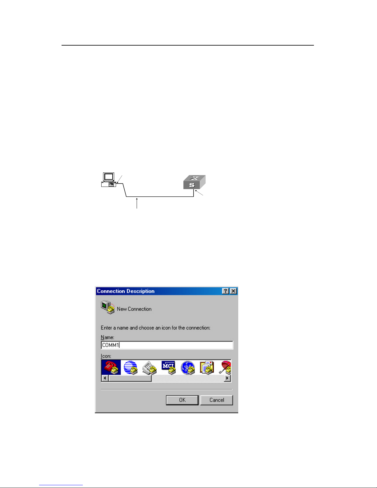
Step 1: As shown in the figure below, to set up the local configuration environment,
connect the serial port of a PC (or a terminal) to the Console port of the switch with the
Console cable.
Console port
RS-232 Serial port
Console cable
Figure 2-1 Setting up the local configuration environment via the Console port
Step 2: Run terminal emulator (such as Terminal on Windows 3X or the Hyper Terminal
on Windows 9X) on the Computer. Set the terminal communication parameters as
follows: Set the baud rate to 9600, databit to 8, parity check to none, stopbit to 1, flow
control to none and select the terminal type as VT100.
Figure 2-2 Setting up new connection
Page 14

Operation Manual - Getting Started
Quidway S3000-EI Series Ethernet Switches Chapter 2
Logging in Switch
Huawei Technologies Proprietary
2-2
nnection
Figure 2-3 Configuring the port for co
Figure 2-4 Setting communication parameters
Step 3: The switch is powered on. Display self-test information of the switch and prompt
you to press Enter to show the command line prompt such as <Quidway>.
Step 4: Input a command to configure the switch or view the operation state. Input a “?”
for an immediate help. For details of specific commands, refer to the following chapters.
Page 15
Operation Manual - Getting Started
Quidway S3000-EI Series Ethernet Switches Chapter 2
Logging in Switch
Huawei Technologies Proprietary
2-3
Environment through Telnet
VLAN interface for a switch via
nd in VLAN interface view), and added the port
command in VLAN view), you can
ole port before the user logs in by
2.2 Setting up Configuration
2.2.1 Connecting a PC to the Switch through Telnet
After you have correctly configured IP address of a
Console port (using ip address comma
(that connects to a terminal) to this VLAN (using port
telnet this switch and configure it.
Step 1: Authenticate the Telnet user via the Cons
Telnet.
Note:
By default, the password is required for authentic
switch. If a user logs in via the Telnet without pa
password has not been set !”.
ating the Telnet user to log in the
ssword, he will see the prompt “Login
<Quidway> system-view
[Quidway] user-interface vty 0
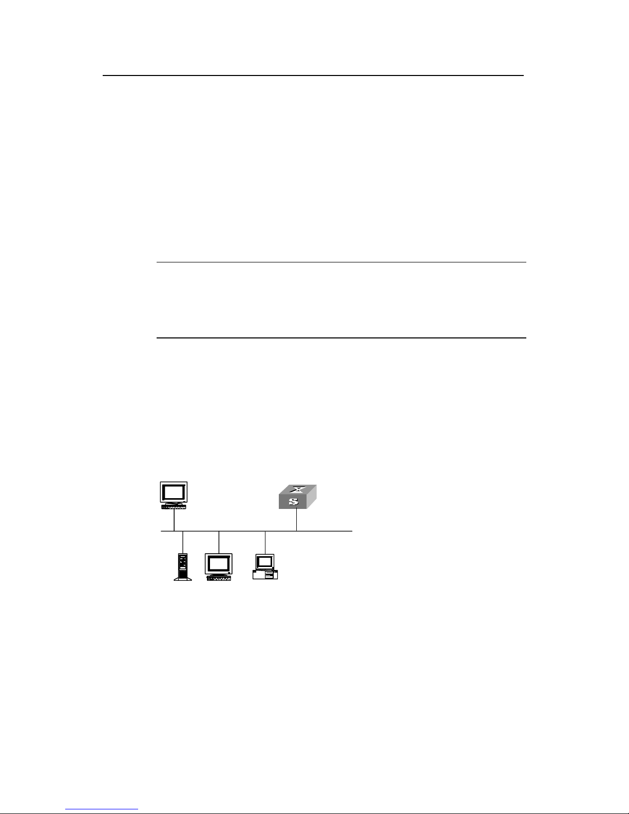
Step 2: To set up the configuration environment, connect the Ethernet port of the PC to
[Quidway-ui-vty0] set authentication password simple xxxx (xxxx is the preset
login password of Telnet user)
that of the switch via the LAN.
Work sta tion
Ethernet port
Works tation
Server
PC ( for configuring the switch
via Telnet )
Ethernet
Work sta tion
Ethernet port
Works tation
Server
PC ( for configuring the switch
via Telnet )
Ethernet
tep 3: Run Telnet on the PC and input the IP address of the VLAN connected to the PC
Figure 2-5 Setting up configuration environment through telnet
S
port.
Page 16

Operation Manual - Getting Started
Quidway S3000-EI Series Ethernet Switches Chapter 2
Logging in Switch
Huawei Technologies Proprietary
2-4
authentication” and prompts the user to input the
too many users are connected to the switch through the
connect later. At most 5 Telnet users are
es simultaneously.
nfigure the switch or to monitor the
e help. For details of specific commands,
Figure 2-6 Running Telnet
Step 4: The terminal displays “Login
logon password. After you input the correct password, it displays the command line
prompt (such as <Quidway>). If the prompt “All user interfaces are used, please try
later!” appears, it indicates that
Telnet at this moment. In this case, please re
allowed to log on to the Quidway series switch
Step 5: Use the corresponding commands to co
running state. Enter “?” to get the immediat
refer to the following chapters.
Note:
z When configuring the switch via Telnet, do not modify the IP address of it unless
necessary, for the modification might cut the Telnet connection.
ntication to log on to the
z By default, when a Telnet user passes the password authe
switch, he can access the commands at Level 0.
2.2.2 Telneting a Switch through another Switch
After a user has logged into a switch, he or she can config
the switch via Telnet. The local switch serves as
serves as Telnet server. If the ports connecting the
network, their IP addresses must be config
Otherwise, the two switches must establish a route tha
ure another switch through
Telnet client and the peer switch
se two switches are in a same local
ured in the same network segment.
t can reach each other.
As shown in the figure below, after you telnet to a switch, you can run telnet command
other switch.
to log in and configure an
Page 17

Operation Manual - Getting Started
Quidway S3000-EI Series Ethernet Switches Chapter 2
Logging in Switch
Huawei Technologies Proprietary
2-5
Telnet Client
PC
Telnet Server
Figure 2-7 Providing Telnet Clie
nt service
tep 1: Authenticate the Telnet user via the Console port on the Telnet Server (switch)
.
S
before login
Note:
By default, the password is required for authenticating the Telnet user to log in the
itch. If a user logs in via the Telnet without passwo
sw rd, he will see the prompt “Login
password has not been set !”.
the hostname or IP address of the Telnet
Server. If it is the hostname, you need to use the ip host command to specify.)
you will see the prompt such <Quidway>. If
se try later!” appears, it indicates that too
ugh the Telnet at this moment. In this case,
please connect later.
ds to configure the switch or view it running
state. Enter “?” to get the immediate help. For details of specific commands, refer to the
2.3 Setting up Configuration Environment through a Dial-up
the Modem
<Quidway> system-view
[Quidway] user-interface vty 0
[Quidway-ui-vty0] set authentication password simple xxxx (xxxx is the preset
login password of Telnet user)
Step 2: The user logs in the Telnet Client (switch). For the login process, refer to the
section describing “Connecting a PC to the Switch through Telnet”.
Step 3: Perform the following operations on the Telnet Client:
<Quidway> telnet xxxx (xxxx can be
Step 4: Enter the preset login password and
the prompt “All user interfaces are used, plea
many users are connected to the switch thro
Step 5: Use the corresponding comman
following chapters.
Step 1: Authenticate the Modem user via the Console port of the switch before he logs
in the switch through a dial-up Modem.
Page 18

Operation Manual - Getting Started
Quidway S3000-EI Series Ethernet Switches Chapter 2
Logging in Switch
Huawei Technologies Proprietary
2-6
Note:
By default, the password is required for authenticating the Modem user to log in the
without password, he will see an error prompt.
switch. If a user logs in via the Modem
<Quidway> system-view
[Quidway] user-interface aux 0
[Quidway-ui-aux0] set authentication password simple xxxx (xxxx is the preset
------------- Ignore DTR signal
AT&K0 ----------------- ------ Disable flow control
------- -------- Bar the modem to send command response
login password of the Modem user.)
Step 2: Perform the following configurations on the Modem that is directly connected to
the switch. (You are not required to configure the Modem connected to the terminal.)
AT&F ----------------------- Reset Modem factory settings
ATS0=1 -----------------Set auto response (ring once)
AT&D ----------
AT&R1 ----------------------- Ignore RTS signal
AT&S0 ---------------- ------- Force DSR to be high-level
ATEQ1&W --------
or execution result and save the configurations
After the configuration, key in the AT&V command to verify the Modem settings.
Note:
z The Modem configuration commands and outputs may be different according to
different Modems. For details, refer to the User Manual of the Modem.
z It is recommended that the transmission rate on the Console port must lower than
odem, otherwise packets may be lost.
that of M
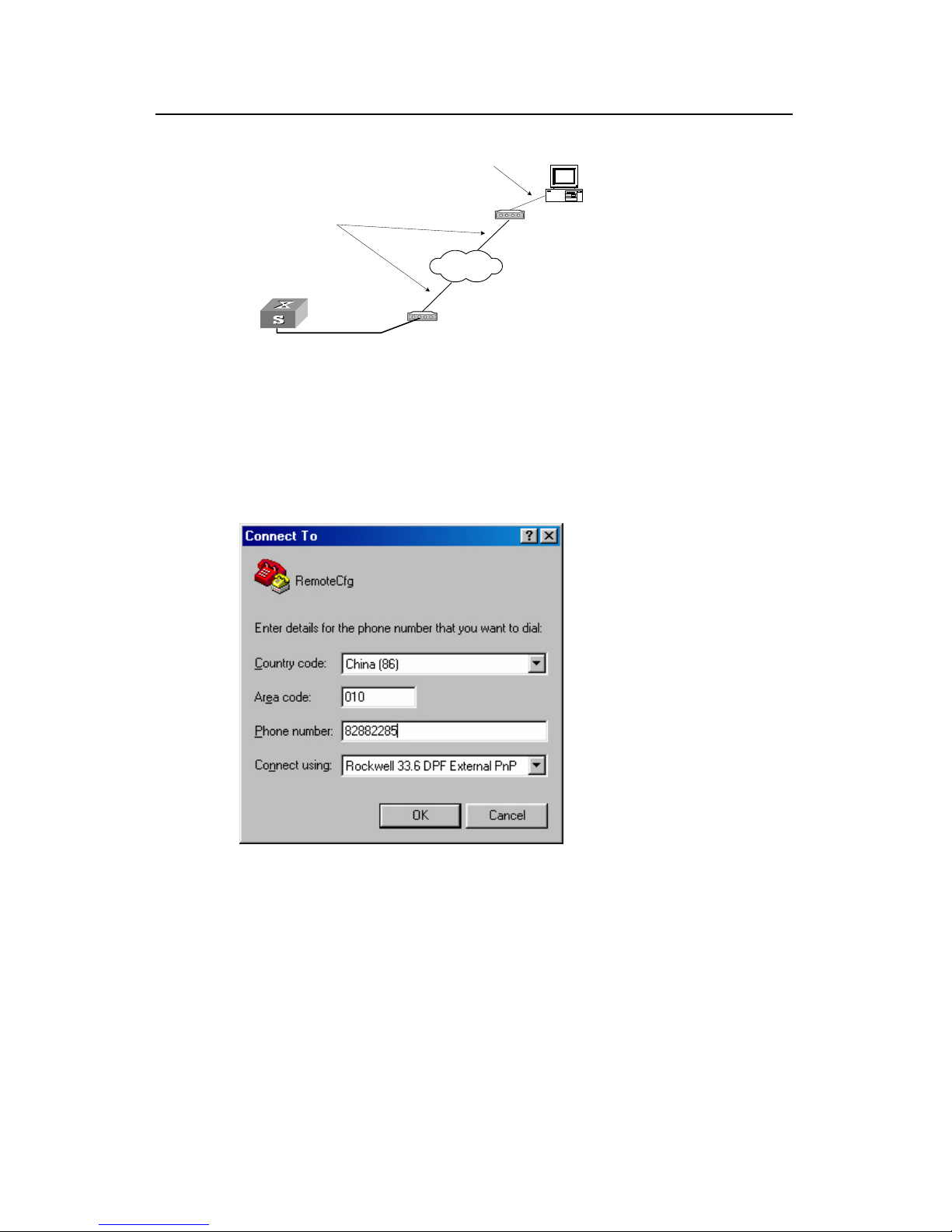
Step 3: As shown in the figure below, to set up the remote configuration environment,
onnect the Modems to a PC (or a terminal) serial port and the switch Console port
c
respectively.
Page 19
Operation Manual - Getting Started
Quidway S3000-EI Series Ethernet Switches Chapter 2
Logging in Switch
Huawei Technologies Proprietary
2-7
Modem serial port line
Modem
Modem
Telephone line
Remote tel:
82882285
Console port
PSTN
Fig
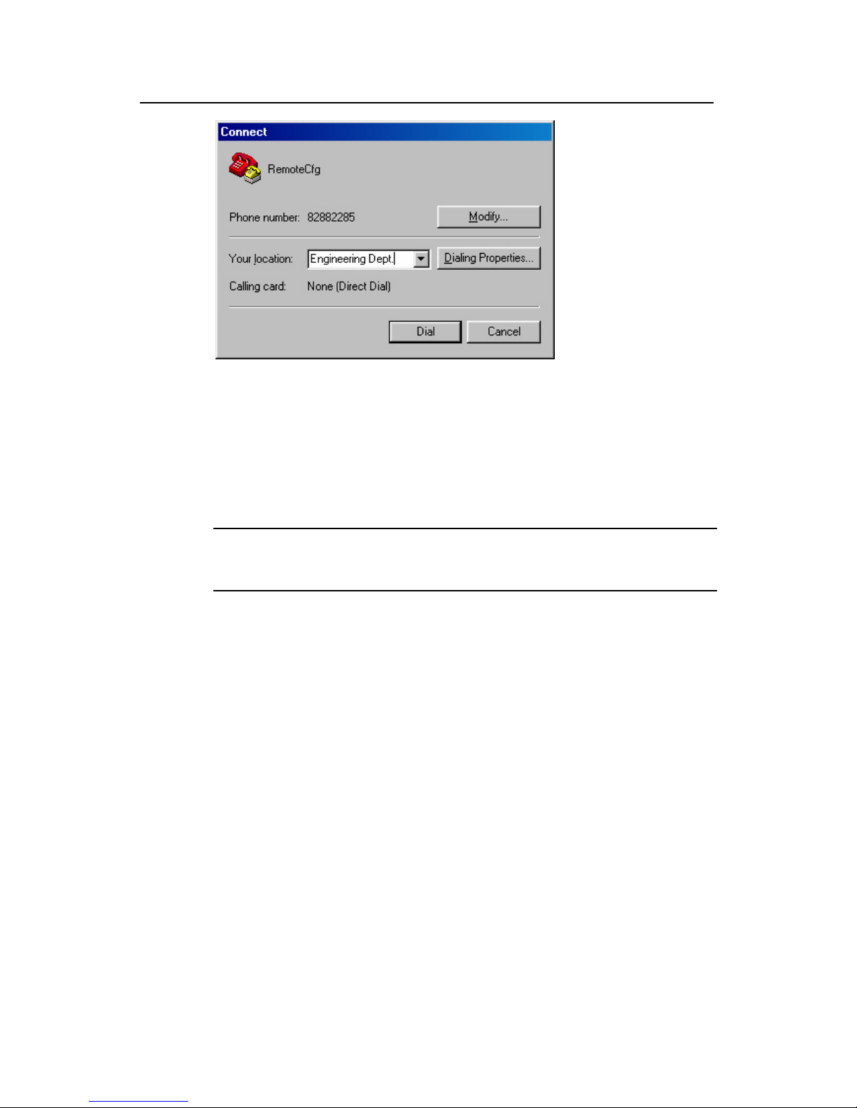
Step 4: Dial or and Modem on the
mote end. The number dialed shall be the telephone number of the Modem
connected to the switch. See the two figures below.
ure 2-8 Setting up remote configuration environment
for connection to the switch, using the terminal emulat
re
Figure 2-9 Setting the dialed number
Page 20
Operation Manual - Getting Started
Quidway S3000-EI Series Ethernet Switches Chapter 2
Logging in Switch
Huawei Technologies Proprietary
2-8
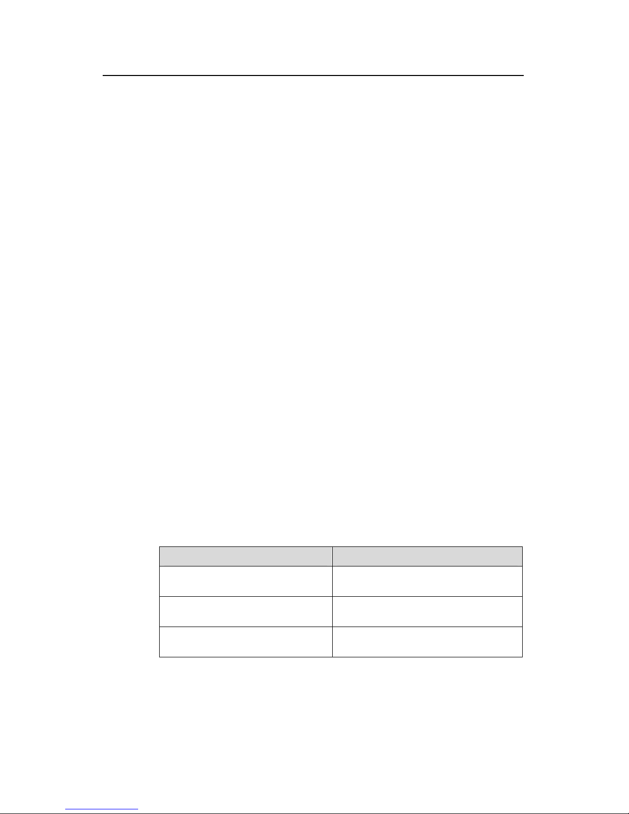
Step 5: Enter the preset login password on the remote terminal emulator and wait for
n you can configure and manage the switch. Enter
“?” to get the immediate help. For details of specific commands, refer to the following
Figure 2-10 Dialing on the remote PC
the prompt such as <Quidway>. The
chapters.
Note:
By default, when a Modem user logs in, he can access the commands at Level 0.
Page 21

Operation Manual - Getting Started
Quidway S3000-EI Series Ethernet Switches Chapter 3 Comm
and Line Interface
Huawei Technologies Proprietary
3-1
Chapter 3 Command Line Interface
3.1 Command Line Interface
Quidway series switches provide a series of configuration commands and command
line interfaces for configuring and managing the switch. The command line interface
has the following characteristics:
z Local configuration via the Console port.
z Local or remote configuration via Telnet or SSH.
z Remote configuration through a dial-up Modem to log in the switch.
z Hierarchy command protection to avoid the unauthorized users accessing switch.
z Enter a “?” to get immediate online help.
z Provide network testing commands, such as Tracert and Ping, to fast troubleshoot
the network.
z Provide various detailed debugging information to help with network
troubleshooting.
z Log in and manage other switch directly, using the Telnet command.
z Provide FTP service for the users to upload and download files.
z Provide the function similar to Doskey to execute a history command.
z The command line interpreter searches for target not fully matching the keywords.
It is ok for you to key in the whole keyword or part of it, as long as it is unique and
not ambiguous.
3.2 Command Line View
Quidway series switches provide hierarchy protection for the command lines to avoid
unauthorized user accessing illegally.
Commands are classified into four levels, namely visit level, monitoring level, system
level and management level. They are introduced as follows:
z Visit level: Commands of this level involve command of network diagnosis tool
(such as ping and tracert), command of switch between different language
environments of user interface (language-mode) and telnet command etc. The
operation of saving configuration file is not allowed on this level of commands.
z Monitoring level: Commands of this level, including the display command and the
debugging command, are used to system maintenance, service fault diagnosis,
etc. The operation of saving configuration file is not allowed on this level of
commands.
Page 22

Operation Manual - Getting Started
Quidway S3000-EI Series Ethernet Switches Chapter 3
Command Line Interface
Huawei Technologies Proprietary
3-2
z System level: Service configuration commands, including routing command and
commands on each network layer, are used to provide direct network service to
z n of the
system and system support module, which plays a support role on service.
ve file system commands, FTP commands, TFTP
ading commands, user management commands,
and level setting commands.
r users of different levels log in, they can only use
commands at the levels that are equal to or lower than its own level.
sion, user will be identified when
itc nd. User ID
is needed (Suppose the user has set the
conf the screen the user cannot see the password that he entered. Only
Othe l user level will remain unchanged.
fe ents. They
r u will enter user
w he running
in wh
view
ng views:
z
z
z
z
z
z
z
ew
z Advanced ACL view
the user.
Management level: They are commands that influence basis operatio
Commands of this level invol
commands, XModem downlo
At the same time, login users are classified into four levels that correspond to the four
command levels respectively. Afte
In order to prevent unauthorized users from illegal intru
sw hing from a lower level to a higher level with super [ level ] comma
authentication is performed when users at lower level switch to users at higher level. In
other words, user password of the higher level
super password [ level level ] { simple | cipher } password.) For the sake of
identiality, on
when correct password is input for three times, can the user switch to the higher level.
rwise, the origina
Dif rent command views are implemented according to different requirem
are elated to one another. For example, after logging in the switch, yo
vie , in which you can only use some basic functions such as displaying t
state and statistics information. In user view, key in system-view to enter system view,
ich you can key in different configuration commands and enter the corresponding
s.
The command line provides the followi
z User view
z System view
z Ethernet Port view
VLAN view
z VLAN interface view
z LoopBack interface view
z Local-user view
User interface view
FTP Client view
Cluster view
z MST region view
RSA public key view
RSA key code view
Basic ACL vi
Page 23

Operation Manual - Getting Started
Quidway S3000-EI Series Ethernet Switches Chapter 3
Command Line Interface
Huawei Technologies Proprietary
3-3
z
z
erver group view
The
ente
Tabl and view
z Layer-2 ACL view
User-defined ACL view
RADIUS s
z ISP domain view
following table describes the function features of different views and the ways to
r or quit.
e 3-1 Function feature of comm
Command
view
Function Prompt
Command to
enter
Command to exit
User view
information about quit disconnects to
Show the basic
Enter right after
operation and
statistics
<Quidway> connecting the
switch
the switch
System
view
Configure system
parameters
[Quidway]
Key in
system-view in
user view
quit or return
returns to user
view
[Quidway-Ether
net0/1]
100M Ethernet
port view
Key in inte
ethernet 0/1
rface
in
system view
Ethernet
Port view
quit returns to
Configure Ethernet
port parameters
[Quidway-Giga
bitEthernet1/1]
GigabitEthernet
port view
Key in interface
gigabitethernet
1/1 in system view
system view
return returns to
user view
VLAN view
1]
in vlan 1 in
system view
quit returns to
system view
return returns to
user view
Configure VLAN [Quidway-Vlan Key
parameters
VLAN
interface
view
C
a
V
ag
[Quidway-Vlan-
ce1]
Key in interface
vlan-interface 1 in
system view
quit returns to
system view
return returns to
user view
onfigure IP
interface
parameters for
LAN or a VLAN
interfa
gregation
Local-user
view
C
pa
[Quidway-luser
-user1]
Key in local-user
user1 in system
view
quit returns to
system view
return returns to
user view
onfigure local user
rameters
User
interface
view
C
interface
pa
0]
Key in
user-interface 0 in
system view
quit returns to
system view
return returns to
user view
onfigure user
[Quidway-ui
rameters
Page 24

Operation Manual - Getting Started
Quidway S3000-EI Series Ethernet Switches Chapter 3
Command Line Interface
Huawei Technologies Proprietary
3-4
Command
view
Function Prompt
Command to
enter
Command to exit
FTP Clien
view C
Key in ftp in user
view
quit returns to
system view
t Configure FTP
lient parameters
[ftp]
Cluster
view er] system view
quit returns to
return returns to
user view
Configure Cluster
parameters
[Quidway-clust Key in cluster in
system view
MST region
view
Config
regio rs
[Quidway-m
egi
Key in stp
re t
ion in view
quit returns to
system view
user view
ure MST
n paramete
st-r
on]
gion-configura
system
return returns to
RSA public
key view
-p
ublic-key] 003 in
ns to
system view
Configure RSA
public key of SSH
user
[Quidway-rsa
Key in rsa
peer-public-key
quidway
system view
peer-public-key
end retur
RSA key
code view
blic key
of SSH user
[Quidway-rsa-k
ey-code]
-code
turns to RSA
lic key view
Edit RSA pu
Key in
public-key
begin in RSA
public key view
pub
public-key-code
end re
Basic ACL Define the rule of y-acl-
basic-2000]
quit returns to
s to
view basic ACL
[Quidwa
Key in acl number
2000 in system
view
system view
return return
user view
Advanced
ACL view
Define the rule of
advanced ACL
Key in acl number
rns to
system view
return returns to
user view
[Quidway-acl-a
dv-3000]
3000 in system
view
quit retu
Layer-2
ACL view
Define the rule of
layer-2 ACL
[Quidway-acl-li
nk-
4000]
Key in acl number
4000 in system
view
quit returns to
system view
return returns to
user view
User-de
ed AC
view
fin
L
Define the rule of
user-defined ACL
[Quidway-acl-u
ser-5000]
Key in acl number
5000 in system
view
quit returns to
system view
return returns to
user view
Conform-le
vel view
Configure the
group"
mapping table and
"Local-precedence
+ Conform-level
802.1p priority"
mapping table
[Quidway-conf
orm-level-0]
in qos
conform-level 0 in
system view
returns to
return returns to
user view
"DSCP +
Conform-level
Service
Key
quit
system view
Page 25

Operation Manual - Getting Started
Quidway S3000-EI Series Ethernet Switches Chapter 3
Command Line Interface
Huawei Technologies Proprietary
3-5
Command
view
Function Prompt
Command to
enter
Command to exit
WRED
index view
Configure WRED
parameters
[Quidway-wred
-0]
Key in wred 0 in
system view
quit returns to
system view
return returns to
user view
RADIUS
server
group view
s
parameters
[Quidway-radiu
s-1]
i radius
scheme 1 in
system view
Configure radiu
Key n
quit returns to
system view
return returns to
user view
ISP domain
view
Configure ISP
domain parameters
[Quidway-isp-h
uawei163.net]
Key in domain
huawei163.net in
w
system view
quit returns to
system vie
return returns to
user view
3 s d
3.3.1 Online Help of Command Line
fo
z
z
Partial help
You can get the help information through o
1) Input “?” in any view to get all the comm in it and corres
<Quidway> ?
Us
boot Set boot option
cd Change current directory
clock Specify the system clock
c il
eb
delete Delete a file
dir List files on a file system
display Display current system information
2) Input a command with a “?” separated pace. If this position is for key
all the keywords and the corresponding brief descriptions will be listed.
<Quidway> language-mode ?
chinese Chinese environment
english English environment
.3 FeaturesFeature and Function of Comman Line
The command line interfa
Full help
ce provides the llowing online help modes.
these online help c
ands
mmands, which are
described as follows.
ponding descriptions.
er view commands:
opy C
debugging E
opy from one f
nable system d
e to another
ugging functions
(Omitted)
by a s words,
Page 26
Operation Manual - Getting Started
Quidway S3000-EI Series Ethernet Switches Chapter 3
Command Line Interface
Huawei Technologies Proprietary
3-6
3) Input a command with a “?” separated by a space. If this position is for parameters,
all the parameters and their brief descriptions will be listed.
[Q
<1-4094> VLAN interface number
[Quidway] interface vlan 1 ?
<c ram s po next co
the command, you can press <Enter> to execute it directly.
4) cter string with a “?”, then all the commands with this character string
as their initials will be listed.
<Q
i
5) Input a command with a character string and “?”, then all th s with this
character string as their initials in the command will be listed
<Q
Input the first letters of a keyword of a co press < If no other
keywords are headed by this letters, then this unique keyw
7) y
language-mode command.
3.3.2 Displaying Characteristics of Command Line
z For users’ convenience, the instruction and help information can be displayed in
ayed exceeding one screen, pausing function is
he table below.
ns of displaying
uidway] interface vlan ?
<cr>
r> indicates no pa
Input a chara
eter in thi sition. The mmand line repeats
uidway>pi?
ng
p
e key word
.
uidway> display ver?
version
6) mmand and Tab> key.
ord will be displayed
automatically.
To switch to the
Chinese displa for the above information, perform the
Command line interface provides the following display characteristics:
both English and Chinese.
z For the information to be displ
provided. In this case, users can have three choices, as shown in t
Table 3-2 Functio
Key or Command Function
Press <Ctrl+C> when the display
pauses
Stop displaying and executing command.
Enter a space when the display Continue to display the next screen of
pauses
information.
Press <Enter> when the display Continue to display the next line of
formation.
pauses
in
Page 27

Operation Manual - Getting Started
Quidway S3000-EI Series Ethernet Switches Chapter 3
Command Line Interface
Huawei Technologies Proprietary
3-7
3.3.3 Hist
Key. The commands
rs can be automatically saved by the command line interface and you
10. T ach user.
e table below.
d
ory Command of Command Line
Command line interface provides the function similar to that of Dos
entered by use
can invoke and execute them at any time later. History command buffer is defaulted as
hat is, the command line interface can store 10 history commands for e
The operations are shown in th
Table 3-3 Retrieving history comman
Operation Key Result
Dis
com
command by user play history
mand
display
history-command
Display history
inputting
Retrieve the
Up cursor key
previous history
<↑> or Retrieve the previous history
command, if there is any.
command
<Ctrl+P>
Retrieve the next Down cursor key <↓> Retrieve the next history
history command or <Ctrl+N> command, if there is any.
Note:
Cursor keys can be used to retrieve the history commands in Windows 3.X Terminal
rk, b
same purpose.
and Telnet. However, in Windows 9X HyperTerminal, the cursor keys ↑ and ↓ do not
wo ecause Windows 9X HyperTerminal defines the two keys differently. In this
keys <Ctrl+P> and <Ctrl+N> instead for the
case, use the combination
3.3.4 Common Command Line Error Messages
gram messages will be reported to users. The common
Table 3-4 Common command line error messages
All the input commands by users can be correctly executed, if they have passed the
mar check. Otherwise, error
error messages are listed in the following table.
Error messages Causes
Cannot find the command.
Cannot find the keyword.
Wrong parameter type.
Unrecognized command
The value of the parameter exceeds the range.
Incomplete command The input command is incomplete.
Too many parameters Enter too many parameters.
Page 28

Operation Manual - Getting Started
Quidway S3000-EI Series Ethernet Switches Chapter 3
Command Line Interface
Huawei Technologies Proprietary
3-8
e parameters entered are not specific. Ambiguous command Th
3.3.5 Editing Characteristics of Command Line
C line interface provides the bas diting function and supports to
e
Table 3-5 Editing functions
ommand ic command e
dit multiple lines. A command cannot longer than 256 characters. See the table below.
Key Function
Common keys
Insert from the curso
right, if the edition
r position and the cursor moves to the
buffer still has free space.
Backspace
Delete the character preceding the cursor and the cursor
moves backward.
Leftwards cursor key
<←> or <Ctrl+B>
Move the cursor a character backward
Rightwards cursor key
<→> or <Ctrl+F>
Move the cursor a c
haracter forward
Up cursor key <↑> or
<Ctrl+P>
Dow <↓>
Retrieve the history command.
n cursor key
or <Ctrl+N>
<Tab>
system
Press <Tab> after typin plete key word and the
will execute the partial help: If the key word
one with the c lay it in
a new line; if there is not a matched key word or the
n
but display a new
line.
g the incom
matching the typed one
the typed
is unique, the system will replace
omplete key word and disp
matched key word is
modification
ot unique, the system will do no
the originally typed word in
Page 29

Operation Manual - Getting Started
Quidway S3000-EI Series Ethernet Switches Chapter 4 Use
r Interface Configuration
Huawei Technologies Proprietary
4-1
C
4.1 User Interface Overview
User in n is another way provided witch to configure and
manage the port data.
S3000-EI Series Ethernet Switc onfiguration methods:
z the Con
z Local and remote configuration thro H on Ethernet port
z Remote configuration throu
A mention two types of user
in
z
UX user interface is used to log in the switch via the Console port. A switch can only
have one AUX user interface.
VTY user interface is used to telnet the switch. A switch can have up to five VTY user
Note:
hapter 4 User Interface Configuration
terface configuratio by the s
hes support the following c
Local configuration via sole port
ugh Telnet or SS
gh dial with modem via the Console port.
ccording to the above- ed configuration methods, there are
terfaces:
AUX user interface
A
z VTY user interface
interface.
For Quidw s switches, AUX port and Cons the same one. There is
only the type of AUX user
ay serie ole port are
interface.
User interface is numbered in the following two ways: absolute number and relative
n
1) Absolute number, following the rules below.
z ated as user interface
z r AUX user interface. The absolute number of the first VTY is
incremented by 1 tha
2 presented by “+ number” assigned to each type of user
interface. It follows the rules below:
z Number of AUX user interface: AUX 0.
z Number of VTY: The first VTY interface is designated as VTY 0, the second one is
designated as VTY 1, and so on.
umber.
AUX user interface is
0.
numbered as the first interface design
VTY is numbered afte
n the AUX user interface number.
) Relative number, re
Page 30
Operation Manual - Getting Started
Quidway S3000-EI Series Ethernet Switches Chapter 4 Use
r Interface Configuration
Huawei Technologies Proprietary
4-2
4.2 User Interface Confi
User interface configuratio
z ring user interfac
z Configuring the user
z Configuring the attrib
Configuring the terminal attributes
Managing users
z redirection
4.2.1 Entering User Interface View
The following command is used for entering a user interface view. You can enter a
single user interface view or multi user interface view to configure one or more user
interfaces respectively.
Perform the following configuration in system view.
Table 4-1 Entering user interface view
guration
n includes:
e view
interface-supported protocol
utes of AUX (Console) port
Ente
z
z
Operation Command
Enter a single user interface view or multi
user interface views
user-interface [ type ] first-number
[ last-number ]
4.2.2 Configuring the User Interface-Supported Protocol
The following command is used for setting the supported protocol by the current user
interface. You can log in switch only through the supported protocol. The configuration
becomes effective when you log in again.
Perform the following configurations in user interface (VTY user interface only) view.
Table 4-2 Configuring the user interface-supported protocol
Operation Command
Configure the user interface-supported
protocol
protocol inbound { all | ssh |
telnet }
By default, the user interface supports Telnet and SSH protocols.
Page 31

Operation Manual - Getting Started
Quidway S3000-EI Series Ethernet Switches Chapter 4
User Interface Configuration
Huawei Technologies Proprietary
4-3
Caution:
z If Telnet protocol is specified, to ensure a successful login via the Telnet, you must
configure the password by default.
If SSH protocol is specified, to ensure a successful login, you must configure the
tion of username and password using the
authentication-mode scheme command. The protocol inbound ssh
e none. When you configure SSH protocol successfully for the
z
local or remote authentica
configuration fails if you configure authentication-mode password and
authentication-mod
user interface, then you cannot configure authentication-mode password and
authentication-mode none any more.
4.2.3 Con
s can be used for configuring the attributes of the AUX
(Con speed, flow control, parity, stop bit and data bit.
I. ission speed on AUX (Console) port
figuring the Attributes of AUX (Console) Port
The following command
sole) port, including
Perform the following configurations in user interface (AUX user interface only) view.
Configuring the transm
Table 4-3 Configuring the transmission speed on AUX (Console) port
Operation Command
Configure the transmission speed on AUX (Console) port
speed speed-value
Restore the default transmission speed on AUX (Console)
undo speed
port
By default, the transmission speed on AUX (Console) port is 9600bps.
II the flow control on AUX (Console) port . Configuring
Table 4-4 Configuring the flow control on AUX (Console) port
Operation Command
Configure the flow control on AUX
(C nsole) port
flow-control { hardware | none |
software }
o
Re ntrol mode on
AUX (Console) port
undo flow-control
store the default flow co
efault, the flow control on the AUX (C
By d onsole) port is none, that is, no flow control
will be performed.
Page 32

Operation Manual - Getting Started
Quidway S3000-EI Series Ethernet Switches Chapter 4
User Interface Configuration
Huawei Technologies Proprietary
4-4
III
Table 4-5 Configuring parity on the AUX (Console) port
. Configuring parity on the AUX (Console) port
Operation Command
Configure parity mode on the AUX (Console) parity { even | mark | none |
odd | space }
port
R store the default parity mode
e
undo parity
By default, the parity on the AUX (Console) port is none, that is, no parity bit.
IV bit of AUX (Console) port
Table 4-6 Configuring the stop bit of AUX (Console) port
. Configuring the stop
Operation Command
Configure the stop bit of AUX (Console) port
stopbits { 1 | 1.5 | 2 }
Restore the default stop bit of AUX (Console) port
undo stopbits
By default, AUX (Console) port supports 1 stop bit.
V onsole) port
Table 4-7 Config a bit of AUX (Console) port
. Configuring the data bit of AUX (C
uring the dat
Operation Command
Configure the data bit of AUX (Console) por bits { 7 | 8 } t
data
Restore the default data bit of AUX (Console) port
undo databits
By default, AUX (Console) port supports 8 data bits.
4.2.4 Con
The following commands can be used for configuring the terminal attributes, including
r
interface, configuring terminal screen length and history command buffer size.
Perform the following configuration in user interface view. Perform lock command in
user view.
I. Enabling/disabling terminal service
fter the terminal service is disabled on a user interface, you cannot log in to the switch
through the user interface. However, the user logged in through the user interface
fter such user logs
figuring the Terminal Attributes
enabling/disabling terminal service, disconnection upon timeout, lockable use
A
before disabling the terminal service can continue his operation. A
Page 33

Operation Manual - Getting Started
Quidway S3000-EI Series Ethernet Switches Chapter 4
User Interface Configuration
Huawei Technologies Proprietary
4-5
ut, he cannot log in again. In this case, a user can log in to the switch through the user
ce only when the terminal service is enabled again.
Tabl ing/disabling terminal service
o
interfa
e 4-8 Enabl
Operation Command
Enable terminal service
shell
Disable terminal service
undo shell
By
Note the following point
z
ce.
You cannot use this command on the user interface via which you log in.
z You will be asked to confirm before using undo shell on any legal user interface.
default, terminal service is enabled on all the user interfaces.
s:
For the sake of security, the undo shell command can only be used on the user
interfaces other than AUX user interfa
z
II. Configuring idle-timeout
Table 4-9 Configuring idle-timeout
Operation Command
Configure idle-timeout
idle-timeout minutes [ seconds ]
Restore the default idle-timeout
undo idle-timeout
By default, idle-timeout is enabled and set to 10 minutes on all the user interfaces. That
is, the user interface will cted automatically after 10 minutes without any
ope
idle-tim
III.
his configuration is to lock the current user interface and prompt the user to enter the
after the user
leaves.
be disconne
ration.
eout 0 means disabling idle-timeout.
Locking the user interface
T
password. This makes it impossible for others to operate in the interface
Table 4-10 Locking the user interface
Operation Command
Lock user inter
lock
face
IV. Setting the screen length
Page 34

Operation Manual - Getting Started
Quidway S3000-EI Series Ethernet Switches Chapter 4
User Interface Configuration
Huawei Technologies Proprietary
4-6
a command displays more than one screen of information, you can use the following
Table 4-11 Setting the screen length
If
command to set how many lines to be displayed in a screen, so that the information can
be separated in different screens and you can view it more conveniently.
Operation Command
Set the screen length
screen-length sc
reen-length
Restore the default scre
undo screen-length
en length
By default, the terminal screen length is 24 lines.
s le screen display nction.
V. Setting the history command buffer size
Table 4-12 Setting the history command buffer size
creen-length 0 indicates to disab separation fu
Operation Command
Set the history command buffer size
history-command max-size value
Restore the default history command
buffer size
undo history-command ze
max-si
B mands
an be saved.
4.2.5 Man
r logon authentication method,
level of command which a user can use after logging on, level of command which a
erface, and command level.
I. Configuring the authentication method
T he user n method to
d
erform the following configuration in user interface view.
y default, the size of the history command buffer is 10, that is, 10 history com
c
aging Users
The management of users includes the setting of use
user can use after logging on from the specifically user int
he following command is used for configuring t login authenticatio
eny the access of an unauthorized user.
P
Table 4-13 Configuring the authentication method
Operation Command
Configure the authentication aut
method
hentication-mode { password |
scheme }
Configure no authentication
authentication-mode none
Page 35

Operation Manual - Getting Started
Quidway S3000-EI Series Ethernet Switches Chapter 4
User Interface Configuration
Huawei Technologies Proprietary
4-7
password is required for authenticating the Modem and Telnet users when
they log in.
n to the user interface
Table 4-14 Configuring the local authentication password
By default, terminal authentication is not required for users log in via the Console port,
whereas the
1) Perform local password authenticatio
Using authentication-mode password command, you can perform local password
authentication. That is, you need use the command below to configure a login
password in order to login successfully.
Perform the following configuration in user interface view.
Operation Command
Configure authentication set authen word { cipher |
simple }password
the local
password
tication pass
Remove the local a
password
uthentication
et authentication password
undo s
# Configure for password authentication when a user logs in through a VTY 0 user
ord to huawei.
[Quidway] user-interface vty 0
[Quidway-ui-vty0] set authentication password simple huawei
scheme command, you can perform local or remote
authentication of username and password. The type of the authentication depends on
rmation, see “Security” section.
In the followin ocal username and password re configured.
# password au rough VTY 0
u e a nd huawei respectively.
user-zbr] service-type telnet
ne
interface and set the passw
[Quidway-ui-vty0] authentication-mode password
2) Perform local or remote authentication of username and password to the user
interface
Using authentication-mode
your configuration. For detailed info
g example, l authentication a
Perform username and thentication when a user logs in th
ser interface and set the usernam nd password to zbr a
[Quidway-ui-vty0] authentication-mode scheme
[Quidway-ui-vty0] quit
[Quidway] local-user zbr
[Quidway-luser-zbr] password simple huawei
[Quidway-l
3) No authentication
[Quidway-ui-vty0] authentication-mode no
Page 36

Operation Manual - Getting Started
Quidway S3000-EI Series Ethernet Switches Chapter 4
User Interface Configuration
Huawei Technologies Proprietary
4-8
Note:
By default, the password is required for authenticating the Modem and Telnet users
when they log in. If the password has not been set, when a user logs in, he will see the
prompt “
Login password has not been set !”.
If the authentication-mode none command is used, the Modem and Telnet users will
not be required to input password.
II vel used after a user logging in
g the command level used after a user logging
. Setting the command le
The following command is used for settin
in.
Perform the following configuration in local-user view.
Table 4-15 Setting the command level used after a user logging in
Operation Command
Set command level used after a
se
user logging
rvice-type { ftp [ ftp-directory directory ] |
lan-access | ssh [ | telnet [ level
level ] ] | telnet [ lev [ level level ] ] }
in
level level
el level | ssh
Restore the default command
un -directory ] |
lan telnet [ level ] ] | telnet
[ le
level used after a user logging in
do service-type { ftp [ ftp
-access | ssh [ level |
vel | ssh [ level ] ] }
By default, the specified logon user can access the commands at Level 1.
II interface
ommand level after a user logs in from
a specific user interface, so that a user is able to execute the commands at such
Perform the follo ation in user interface view.
T used a
in
I. Setting the command level used after a user logs in from a user
You can use the following command to set the c
command level.
wing configur
able 4-16 Setting the command level fter a user logging in from a user
terface
Operation Command
Set command level used after a user logging in from a
user interface
user privilege level
level
Restore the d
logging in from
efault command level used after a user
a user interface
undo user privilege
level
Page 37

Operation Manual - Getting Started
Quidway S3000-EI Series Ethernet Switches Chapter 4
User Interface Configuration
Huawei Technologies Proprietary
4-9
r can access the commands at Level 3 after logging in through the
AUX user interface, and the commands at Level 0 after logging in through the VTY user
Note:
By default, a use
interface.
When users log into the switch, the commands they can use depend jointly on the user
level settings and the command level settings on the user interface. If the two types of
entication, the commands they can use are
use is set to level 3 and the
command level on the VTY 0 user interface is level 1, he or she can only use the
to the switch from the VTY 0 user
interface.
settings differ,
z For the users using AAA/RADIUS auth
determined by the user level settings. For example, if a
commands of level 3 or lower when logging in
IV.
he following command is used for setting the priority of a specified command in a
rements.
Set command priority
T
certain view. The command levels include visit, monitoring, system, and management,
which are identified with 0 through 3 respectively. An administrator assigns authorities
as per user requi
Perform the following configuration in system view.
Table 4-17 Setting the command priority
Operation Command
Set the command priority in a specified
command-privilege level level view
d
view.
view comman
Restore the default command level in a
Undo command-privilege view view
specified view.
command
Note:
Please do not change the command level at will for it may cause inconvenience of
m
aintenance and operation.
4.2.6 Con
I. send command
The following command can be used for sending messages between user interfaces.
figure Redirection
Page 38

Operation Manual - Getting Started
Quidway S3000-EI Series Ethernet Switches Chapter 4
User Interface Configuration
Huawei Technologies Proprietary
4-10
Perform the following configuration in user view.
Table 4-18 Configuring to send messages between different user interfaces.
Operation Command
Configuring to send messages between different
user interfaces.
send { all | number | type
number }
II
r a
l be automatically executed when
ed to automatically execute telnet command on the
d device automatically.
ce view.
mmand
. auto-execute command
The following command is used to automatically run a command after you log in. Afte
command is configured to be run automatically, it wil
you log in again.
This command is usually us
terminal, which will connect the user to a designate
Perform the following configuration in user interfa
Table 4-19 Configuring to automatically run the co
Operation Command
Configure to automatically run the command
auto-execute command text
Configure not to automatically run the command
undo auto-execute command
Note the following points:
z After executing this command, the user interface can no longer be used to carry
out the routine configurations
for the local system. Use this command with
caution.
Make sure that you will be able to log in the system in some other way and cancel
the configuration, before you use the auto-execute command command and
idway-ui-vty0] auto-execute command telnet 10.110.100.1
10.110.100.1 automatically.
4.3 Disp
After the above configuration, exec
r u .
Execute free command in user view
z
save the configuration.
# Telnet 10.110.100.1 after the user logs in through VTY0 automatically.
[Qu
When a user logs on via VTY 0, the system will run telnet
laying and Debugging User Interface
ute display command in any view to display the
ration, and to verify the effect of the configuration
to clear a specified user interface.
unning of the user interface config
Page 39

Operation Manual - Getting Started
Quidway S3000-EI Series Ethernet Switches Chapter 4
User Interface Configuration
Huawei Technologies Proprietary
4-11
Table 4-20 i Displaying and debugg ng user interface
Operation Command
Clear a specified user interface
free user-interface [ type ]
number
Display the user application information of the
display users [ all ]
user interface
Display the physical attributes and some display user-interface [ type
configurations of the user interface
number ] [ number ]
Page 40

Operation Manual - Getting Started
Quidway S3000-EI Series Ethernet Switches Chapte
r 5 System IP Configuration
Huawei Technologies Proprietary
5-1
5.1 System IP Overview
5.1.1 Man
Before performi anagement such as Telnet an gement, the IP
address of the switch has to be configured first. For the Quidway series Layer 2
E
VLAN that corresponds to this interface becomes the management VLAN.
5.1.2 IP Ad
I. IP address classification and indications
is a 32-bit address allocated to the devices which access into the Internet. It
Chapter 5 System IP Configuration
agement VLAN
ng remote m d web mana
thernet switch, only one VLAN interface can be configured with an IP address, and the
dress
IP address
consists of two fields: net-id field and host-id field. There are five types of IP address.
See the following figure.
0 1 2 3 4 5 6 7 8 9 10 11 12 13 14 15 16 17 18 19 20 21 22 23 24 25 26 27 28 29 30 31
0
1 0
1 1 0
1 1 1 0
1 1 1 1 0
net-id
net-id
net-id
Multicast address
Class D
Reserved address
host-id
host-id
host-id
Class E
igure 5-1 Five classes of IP address
Class C are unicast addresses, while Class D addresses
are multicast ones and class E addresses are reserved for special applications in future.
tation. Each integer corresponds to one byte, e.g.10.110.50.101.
Class A
Class B
Class C
F
Where, Class A, Class B and
The first three types are commonly used.
The IP address is in dotted decimal format. Each IP address contains 4 integers in
dotted decimal no
Page 41

Operation Manual - Getting Started
Quidway S3000-EI Series Ethernet Switches Chapte
r 5 System IP Configuration
Huawei Technologies Proprietary
5-2
sted in the
Table 5-1 IP address classes and ranges
When using IP addresses, it should also be noted that some of them are reserved for
special uses, and are seldom used. The IP addresses you can use are li
following table.
Network
class
Address
range
IP network
range
Note
A 127.255.2
126.0.0.0
st ID
icate
rk
network routing.
Host ID with all the digits being 1
indicates the broadcast address, i.e.
broadcast to all hosts on the network.
rk number.
f 127.X.Y.Z
st and the
ress will not be
output to the line. The packets are
input packets.
0.0.0.0 to
1.0.0.0 to
IP address 0.0.0.0 is used for the host
that is not put into use after starting up.
55.255
The IP address with network number as
0 indicates the current network and its
network can be cited by the router
without knowing its netwo
Ho
ind
with all the digits being 0
s that the IP address is the
netwo address, and is used for
Network ID with the format o
is reserved for self-loop te
packets sent to this add
processed internally and regarded as
B
to
191.255.2
55.255
128.0.0.0 to
191.254.0.0
network routing.
Host ID with all the digits being 1
128.0.0.0
ll the digits being 0
address is the
network address, and is used for
ddress, i.e.
e network.
Host ID with a
indicates that the IP
indicates the broadcast a
broadcast to all hosts on th
C
192.0.
to
o
5.254.0
with all the digits being 0
indicates that the IP address is the
network address, and is used for
network routing.
Host ID with all the digit being 1
indicates the broadcast address, i.e.
etwork.
0.0
192.0.0.0 t
223.255.2
55.255
223.25
Host ID
s
broadcast to all hosts on the n
D
to
239.255.2
None
Address
224.0.0.0
55.255
address
es of class D are multicast
es.
E
240.0.0.0
to
255.255.2
55.254
None
The addresses are reserved for future
use.
Page 42

Operation Manual - Getting Started
Quidway S3000-EI Series Ethernet Switches Chapter 5
System IP Configuration
Huawei Technologies Proprietary
5-3
Network Address IP network
Note
class range range
O
add
as LAN ther
resses
255.255.2
55.255
255.255.255.2
55
255.255.255.255 is used
broadcast address.
opment of the Internet, IP addresses are depleting very fast.
ress allocation method wastes IP addresses greatly. In order to
r, the first
consecutive bits are set to 1s when designing the mask. The mask divides the IP
to two parts: subnet address and host address. The bits 1s in the address
and the mask indicate the subnet address and the other bits indicate the host address.
sk is the default value and the length
P addresses of classes A, B and C, the
divide a Class A network containing more than 16,000,000
work
rk into 8
8.128.0,
). Each
II. Subnet and mask
Nowadays, with rapid devel
The traditional IP add
make full use of the available IP addresses, the concept of mask and subnet is
proposed.
A mask is a 32-bit number corresponding to an IP address. The number consists of 1s
and 0s. Principally, these 1s and 0s can be combined randomly. Howeve
address in
If there is no sub-net division, then its sub-net ma
of "1" indicates the net-id length. Therefore, for I
default values of corresponding sub-net mask are 255.0.0.0, 255.255.0.0 and
255.255.255.0 respectively.
The mask can be used to
hosts or a Class B network containing more than 60,000 hosts into multiple small
networks. Each small network is called a subnet. For example, for the Class B net
address 138.38.0.0, the mask 255.255.224.0 can be used to divide the netwo
subnets: 138.38.0.0, 138.38.32.0, 138.38.64.0, 138.38.96.0, 138.3
138.38.160.0, 138.38.192.0 and 138.38.224.0 (Refer to the following figure
subnet can contain more than 8000 hosts.
Page 43

Operation Manual - Getting Started
Quidway S3000-EI Series Ethernet Switches Chapter 5
System IP Configuration
Huawei Technologies Proprietary
5-4
10001010, 00100110, 000 00000, 00000000
ClassB
138.38.0.0
Subnet mask
255.255.224.0
11111111, 11111111, 111 00000, 00000000
11111111, 11111111, 000 00000, 00000000
Standard
mask
255.255.0.0
Subnet address:
000 Subn 138.38. et address: 0. 0
001 Subnet address: 138.38. 32. 0
010 Subnet address: 138.38. 64. 0
011 Subnet address: 138.38. 96. 0
100 Subnet address: 138.38.128. 0
101 Subnet address: 138.38.160. 0
110 Subnet address: 138.38.192. 0
111 Subnet address: 138.38.224. 0
Subnet
number
Host
number
Subnet address:
Figure 5-2 Subnet division of IP address
5.1.3 Static Route
A static route is a specia ch
administrator. The static route is applied in a
configuration and usage of the static route c
ensure the bandwidth of the important applic
Huawei Layer 2 Series Ethernet Switches ca
login to the switch through the network.
5.2 System IP Configuration
System IP configuration includes:
z Creating/ ting a Ma
z Assigning e r/of
z Setting/deleti agement VLAN
z Enabling/disabling a management VLAN
z Configuring the Hostname and Host IP
z Configuri oute
z Configuri ult
5.2.1 Creating/Deleti anagement VLAN
Perform the fo guration in system view.
l route, whi is manually configured by the network
comparatively simple network. The proper
an improve the network performance and
ations.
n be configured with static route, used for
dele
/deleting th
ng the man
nagement VLAN
IP Address fo
Interface
the Management VLAN Interface
interface description character string
interface
Address
tic routes
ng a static r
ng the defa
ng a M
preference of sta
Interface
llowing confi
Page 44

Operation Manual - Getting Started
Quidway S3000-EI Series Ethernet Switches Chapter 5
System IP Configuration
Huawei Technologies Proprietary
5-5
Table 5-2 Creating/deleting a management VLAN interface
Operation Command
Create a ma VLAN interface
d enter its
in
nagement
view
an
terface vlan-interface vlan-id
Delete a ma t VLAN interface
undo interface vlan-interface vlan-id
nagemen
VLAN specified with the vlan-id parameter before perform this
uration task. But VLAN1 is the default VLAN, which you need not create.
5.2.2 Assigning/Deleting the IP Address for/of the Management VLAN
Interface
witch.
Note that, user create a
config
You can use the following command to configure the IP address for the management
VLAN interface, thus to perform remote management such as Telnet and web
management to s
Perform the following configuration in VLAN interface view.
Table 5-3 Assigning/deleting the IP address for/of the management VLAN interface
Operation Command
Assign the IP address of a
management VLAN interface
ip address ip-address net-mask
Delete the IP address of a
management VLAN interface
undo ip address [ ip-address net-mask ]
By default, the management VLAN interface has no IP address.
ing/Deleting the Management VLAN Interface Description
String
You can use the following command to set/delete management VLAN interface
description character string.
5.2.3 Sett
Character
Perform the following configuration in VLAN interface view.
Table 5-4 Setting/deleting the management VLAN interface description character
string
Operation Command
Set the description character string for
management VLAN interface
description string
Restore the default description character
string of management VLAN interface
undo description string
Page 45

Operation Manual - Getting Started
Quidway S3000-EI Series Ethernet Switches Chapter 5
System IP Configuration
Huawei Technologies Proprietary
5-6
WEI, Quidway Series,
ce name.
gement VLAN
ement
gement VLAN
fect, use the
By default, the description character string is HUA
Vlan-interface1 Interface. Vlan-interface1 is the management VLAN interfa
5.2.4 Enabling/Disabling a Management VLAN Interface
The following command can be used for disabling or enabling the mana
interface. After configuring the related parameters and protocol of the manag
VLAN interface, you can use the following command to enable the mana
interface. If you do not want the management VLAN interface to take ef
command to disable it.
Perform the following configuration in VLAN interface view.
Table 5-5 Enabling/disabling a management VLAN interface
Operation Command
Disable management VLAN interface
shutdown
Enable management VLAN interface
undo shutdown
The operation of enabling/disabling management VLAN interface has no effect on the
Ethernet ports in up status, the
Host IP Address
You can use the following command to associate the hostname and host IP address.
hostname, instead of the meaningless IP address,
d the system will translate the
r
up/down status of the Ethernet ports belong to the VLAN.
By default, when all the Ethernet ports belonging to the management VLAN are in down
status, the management VLAN interface is also down, i.e. the management VLAN
interface is disabled. When there is one or more
management VLAN interface is also up, i.e. the management VLAN interface is
enabled.
5.2.5 Configuring the Hostname and
Thereafter you can simple use the
when you perform the applications such as Telnet. An
add ess for you.
Perform the following configuration in system view.
Table 5-6 Configuring the hostname and host IP address
Operation Command
Configure a hostname and host IP
ip host hos
address
tname ip-address
Delete a hostname and host IP address undo ip host hostname [ ip-address ]
By default, there is no hostname associated with any host IP address.
Page 46

Operation Manual - Getting Started
Quidway S3000-EI Series Ethernet Switches Chapter 5
System IP Configuration
Huawei Technologies Proprietary
5-7
5.2.6 Con
You can use the mmand to configure a static ro to the switch via
th
Perform the following configuration in system view.
Configuring a static route
figuring a Static Route
following co ute for login
e network.
Table 5-7
Operation Command
Add a static route
ip route-static ip-address { mask | mask-length } { null
null-interface-number | gateway-address } [ preference
preference-value ]
Delete a static
undo ip route-static ip-address { mask | mask-length }
route
[ null
null-interface-number | gateway-address ] [ preference
preference-value ]
figuring the Default Preference of Static Routes 5.2.7 Con
s preference is not
Perform the f figurations in system view.
T
The default-preference will be the preference of the static route if it
specified when configured. You can change the default preference value of the static
routes to be configured by using the following command.
ollowing con
able 5-8 Configuring the default preference of static routes
Operation Command
Configure the default preference valu
static routes
atic default-preference
default-preference-value
e of
ip route-st
Remove the default preference value of
undo ip route-static
ce
static routes configure
default-preferen
By default
, its value is 60.
5.3 Disp
After the above configuration, execute display command in any view to display the
t of the configuration.
laying and Debugging System IP
running of the system IP configuration, and to verify the effec
Page 47

Operation Manual - Getting Started
Quidway S3000-EI Series Ethernet Switches Chapter 5
System IP Configuration
Huawei Technologies Proprietary
5-8
Table 5-9 Displaying and debugging system IP
Operation Command
View all the hosts and their IP addresses
on the network
display ip host
View related IP information of the
display ip interface vlan-interface
management VLAN interface
vlan-id
View related information of the
display interface vlan-interface
management VLAN interface [ vlan_id ]
View routing table summary
display ip routing-table
View routing table details
display ip routing-table verbose
View the detailed
specific route
information of a
display ip routing-table ip-address
[ mask ] [ longer-match ] [ verbose ]
view the route information in the
display ip rou
specified address range
ting-table ip_address1
mask1 ip_address2 mask2 [ verbose ]
View the route filtered through specified
display ip routing
basic access co )
-table acl
{ acl-number | a erbose ] ntrol list (ACL cl-name } [ v
View the route information that throug
specified ip prefix list
h
di routing-table ip-prefix
ip-p [ verbose ]
splay ip
refix-name
View the routing information found by the
specified protocol
displa able protocol
protocol [ inactive | verbose ]
y ip routing-t
View the tree routing table
display ip routing-table radix
View the statistics of the routing table
display ip routing-t
able statistics
Page 48

Operation Manual - Port
Quidway S3000-EI Series Ethernet Switches Table of Contents
Huawei Technologies Proprietary
i
Table of Contents
Chapter 1 Ethernet Port Configuration ....................................................................................... 1-1
1.1 Ethernet Port Overview...................................................................................................... 1-1
1.2 Ethernet Port Configuration ............................................................................................... 1-2
1.2.1 Enter Ethernet port view.......................................................................................... 1-2
1.2.2 Enable/Disable Ethernet Port.................................................................................. 1-2
1.3 Set Description Character String for Ethernet Port............................................................ 1-3
1.3.1 Set Duplex Attribute of the Ethernet Port................................................................ 1-3
1.3.2 Set Speed on the Ethernet Port .............................................................................. 1-4
1.3.3 Set Cable Type for the Ethernet Port...................................................................... 1-4
1.3.4 Enable/Disable Flow Control for Ethernet Port ....................................................... 1-5
1.3.5 Set Ethernet Port Broadcast Suppression Ratio..................................................... 1-5
1.3.6 Set link type for Ethernet port.................................................................................. 1-6
1.3.7 Add the Ethernet port to Specified VLANs.............................................................. 1-6
1.3.8 Set the Default VLAN ID for the Ethernet Port........................................................ 1-7
1.3.9 Set loopback detection for the Ethernet port........................................................... 1-8
1.3.10 Set the Time Interval of Calculating Port Statistics Information............................ 1-9
1.3.11 Port Traffic Threshold Configuration ..................................................................... 1-9
1.4 Display and Debug Ethernet Port .................................................................................... 1-11
1.5 Ethernet Port Configuration Example .............................................................................. 1-11
1.6 Ethernet Port Troubleshooting......................................................................................... 1-12
Chapter 2 Link Aggregation Configuration ................................................................................ 2-1
2.1 Link Aggregation Overview................................................................................................ 2-1
2.2 Link Aggregation Configuration ......................................................................................... 2-1
2.2.1 Aggregate Ethernet Ports........................................................................................ 2-1
2.3 Display and Debug Link Aggregation ................................................................................ 2-2
2.4 Link Aggregation Configuration Example .......................................................................... 2-2
2.5 Ethernet Link Aggregation Troubleshooting ...................................................................... 2-3
Page 49

Operation Manual - Port
Quidway S3000-EI Series Ethernet Switches Chapter 1
Ethernet Port Configuration
Huawei Technologies Proprietary
1-1
S3026T Ethernet Switch provides 24 10/100Base-T fixed Ethernet ports and two
S3026E FS Ethernet Switch is the fixed
00Base-T fixed Ethernet ports
ng Ethernet port features:
n
z
(full-duplex) and auto
Chapter 1 Ethernet Port Configuration
1.1 Ethernet Port Overview
S3026G Ethernet Switch provides 24 10/100Base-T fixed Ethernet ports and two GBIC
uplink ports. You can select the gigabit optical module.
S3026C Ethernet Switch provides 24 10/100Base-T fixed Ethernet ports and two
extended module slots and supports 100Base-FX Multi-mode module, 100Base-FX
Single Mode module, 1000Base-SX module, 1000Base-LX module, 1000Base-T
module, 1000Base-ZX module, 1000Base-LX GL module and stack module.
10/100/1000Base-T uplink Ethernet ports.
The only difference between S3026E FM and
optical ports with the different attributes they provide: S3026E FM Ethernet Switch
provides 12 fixed 100Base-FX multi-mode Ethernet ports. S3026E FS Ethernet Switch
provides 12 fixed 100Base-FX single-mode Ethernet ports. Each of them also provides
two 6-port 100M module slots and two uplink module slots. The 6-port 100M module
slots support 6-port 10/100Base-T module, 6-port 100Base-FX single-mode module
and 6-port 100Base-FX multi-mode module. The uplink module slots support
100Base-FX multi-mode module, 100Base-FX single-mode module, 1000Base-SX
module, 1000Base-LX module, 1000Base-T electrical port module, 1000Base-ZX
module, 1000Base-LX GL module, and stack module.
S3026C-PWR Ethernet switch provides 24 fixed 10/1
and two extended module slots, which support one-port 1000Base-LX module,
one-port 1000Base-SX module, one-port 1000Base-T module, one-port gigabit long
haul/ medium haul optical interface module, one-port gigabit stack module, one-port
100Base-T single mode/multi-mode optical interface module, one-port 100Base-FX
single mode medium haul optical interface module, one-port 100Base-T SFP interface
module, and one-port gigabit GBIC interface module.
S3000-EI Series Ethernet Switches support the followi
z 10/100Base-T Ethernet port supports MDI/MDI-X auto-sensing. It operates i
half-duplex, full-duplex, or auto-negotiation modes. It can negotiate with other
network devices to determine the operating mode and speed. Thus the suitable
operating mode and speed can be worked out automatically and the system
configuration and management is greatly streamlined.
100Base-FX Multi-mode/Single Mode Ethernet port operates in 100M full-duplex
mode. The operating mode can be set to full
Page 50

Operation Manual - Port
Quidway S3000-EI Series Ethernet Switches Chapter 1
Ethernet Port Configuration
Huawei Technologies Proprietary
1-2
z
ll-duplex) and auto (auto-negotiation) and its speed can be set
The
desc
1.2 Ethernet Port Configuration
z Enter Ethernet port view
string for Ethernet port
et port
r Ethernet port
sion ratio
Ethernet port
rt
s information
1.2.1 Ente
rnet port, enter Ethernet port view first.
Perform the following configuration in system view.
(auto-negotiation) and its speed can be set to 100 (100Mbps) and auto
(auto-negotiation).
Gigabit Ethernet port operates in gigabit full-duplex mode. The operating mode
can be set to full (fu
to 1000 (1000Mbps) and auto (auto-negotiation). 1000Base-T Ethernet port
operates in 1000M full-duplex, 100M half-duplex/full-duplex, and 10M
half-duplex/full-duplex modes.
configurations of these Ethernet ports are basically the same, which will be
ribed in the following sections.
Ethernet port configuration includes:
z Enable/Disable Ethernet port
z Set description character
z Set duplex attribute for Ethern
z Set speed for Ethernet port
z Set cable type for the Ethernet port
z Enable/Disable flow control fo
z Set Ethernet port broadcast suppres
z Set link type for Ethernet port
z Add the Ethernet port to specified VLANs
z Set the default VLAN ID for the
z Set loopback detection for the Ethernet po
z Set the time interval of calculating port statistic
r Ethernet port view
Before configuring the Ethe
Table 1-1 Enter Ethernet port view
Operation Command
Enter Ethernet port view
interface { interface_type
interface_num | interface_name }
1.2.2 Enable/Disable Ethernet Port
The following command can be used for disabling or enabling the port. After configuring
the related parameters and protocol of the port, you can use the following command to
Page 51

Operation Manual - Port
Quidway S3000-EI Series Ethernet Switches Chapter 1
Ethernet Port Configuration
Huawei Technologies Proprietary
1-3
a port to forward data any more, use the command to
disable it.
enable the port. If you do not want
Perform the following configuration in Ethernet port view.
Table 1-2 Enable/Disable an Ethernet port
Operation Command
Disable an Ethernet port
shutdown
Enable an Ethernet port
undo shutdown
B
1.3 Set Description Character Strin et Port
To distinguish the Ethernet ports, you can use the following command to make some
Table 1-3 Set description character string for Ethernet port
y default, the port is enabled.
g for Ethern
necessary descriptions.
Perform the following configuration in Ethernet port view.
Operation Command
Set description character string for Ethernet port.
description text
Delete the description character string of Ethernet.
undo description
By default, the port des ull character string.
1.3.1 Set D
o configure a port to send and receive data packets at the same time, set it to
plex. To configure a port to either send or receive data packets at a time, set it to
ode, the local and peer ports
will automatically negotiate about the duplex mode.
ort view.
cription is a n
uplex Attribute of the Ethernet Port
T
full-du
half-duplex. If the port has been set to auto-negotiation m
Perform the following configuration in Ethernet p
Table 1-4 Set duplex attribute for Ethernet port
Operation Command
Set duplex attribute for Ethernet port.
duplex { auto | full | half }
Restore the default duplex attribute of Ethernet port.
undo duplex
Page 52

Operation Manual - Port
Quidway S3000-EI Series Ethernet Switches Chapter 1
Ethernet Port Configuration
Huawei Technologies Proprietary
1-4
operate in full-duplex, half-duplex or
auto-negotiation mode be set as per the requirement
T pport full dupl in
full ) mode.
The Gi uplex or
uto-negotiation mode. When the port operates at 1000Mbps, the duplex mode can be
1.3.2 Set
You can use the following command to set the speed on the Ethernet port. If the speed
Perform the following confi ation in Ethernet port view.
Table 1-5 Set speed on Ethernet port
Note that, 100M electrical Ethernet port can
, which can s.
he optical 100M/Gigabit Ethernet ports su
(full duplex) or auto (auto-negotiation
ex and can be set to operate
gabit electrical Ethernet port can operate in full duplex, half d
a
set to full (full duplex) or auto (auto-negotiation).
The port defaults the auto (auto-negotiation) mode.
Speed on the Ethernet Port
is set to auto-negotiation mode, the local and peer ports will automatically negotiate
about the port speed.
gur
Operation Command
Set 100M Ethernet port speed
speed { 10 | 100 | auto }
Set Gigabit Ethernet port speed
speed { 10 | 100 | 1000 | auto }
Restore the default speed on Ethernet port
undo speed
Note that, the 100M electrical Ethernet port can operate at 10Mbps, 100Mbps or
requirements.
100M optical Ethe ports 100Mbps and can be co perate at 100
( ion).
T pports the 10 n be
s
The electrical Gigabit Ethernet port can operate at 10Mbps, 100Mbps, or 1000Mbps as
er different requirements. However in half duplex mode, the port cannot operate at
1.3.3 Set
able type.
Perform the following configuration in Ethernet port view.
auto-negotiated speed as per different
rnet port sup nfigured to o
100Mbps) or auto (auto-negotiat
he optical Gigabit Ethernet port su 00Mbps speed and the speed ca
et to 1000 (1000Mbps) or auto (auto-negotiation).
p
1000Mbps.
By default, the speed of the port is in auto mode.
Cable Type for the Ethernet Port
The Ethernet port supports the straight-through and cross-over network cables. The
following command can be used for configuring the c
Page 53

Operation Manual - Port
Quidway S3000-EI Series Ethernet Switches Chapter 1
Ethernet Port Configuration
Huawei Technologies Proprietary
1-5
Table 1-6 Set the type of the cable connected to the Ethernet port
Operation Command
Set the type of the cable connected to
mdi { across | auto | normal }
the Ethernet port.
Restore the default type of the cable
undo mdi
connected to the Ethernet port.
By default, the cable type is auto (auto-recognized).That is, the system can
port.
1.3.4 Ena
After enabling flow control in both the local and the peer switch, if congestion occurs in
th the peer
switch receives this message, it will pause packet sending, and vice versa. In this way,
p ion of the Ethernet port can be
enabled or disabled through the following command.
erform the following configuration in Ethernet port view.
Note that, the settings only take effect on 10/100Base-T and 1000Base-T ports.
automatically recognize the type of cable connecting to the
ble/Disable Flow Control for Ethernet Port
e local switch, the switch will inform its peer to pause packet sending. Once
acket loss is reduced effectively. The flow control funct
P
Table 1-7 Enable/Disable Flow Control for Ethernet Port
Operation Command
Enable Ethernet port flow control
flow-control
Disable Ethernet port flow control
undo flow-contr
ol
1.3.5 Set
he broadcast traffic. Once the
e system will maintain an
w traffic, so as to suppress
al service. The parameter is
taken the maximum wire speed ratio of the broadcast traffic allowed on the port. The
smaller the r maller the broadcast traffic is e ratio is 100%, it
m m n the port.
P
By default, Ethernet port flow control is disabled.
Ethernet Port Broadcast Suppression Ratio
You can use the following commands to restrict t
broadcast traffic exceeds the value set by the user, th
appropriate broadcast packet ratio by discarding the overflo
broadcast storm, avoid suggestion and ensure the norm
atio is, the s allowed. If th
eans not to perform broadcast stor suppression o
erform the following configuration in Ethernet port view.
Page 54

Operation Manual - Port
Quidway S3000-EI Series Ethernet Switches Chapter 1
Ethernet Port Configuration
Huawei Technologies Proprietary
1-6
Table 1-8 Set Ethernet port broadcast suppression ratio
Operation Command
Set Ethernet port broadcast suppression ratio
broadcast-suppression ratio
Restore the default Ethernet port broadcast
suppression ratio
undo broadcast-suppression
By default, 100% broadcast traffic is allowed to pass through, that is, no broadcast
suppression will be performed.
1.3.6 Set link type for Ethernet port
Ethernet port can operate in three different link types, access, hybrid, and trunk types.
The access port c LAN only, used for connectin ’s computer.
T L ts on
m e switches. The hybrid port can also
c VLAN and receive/send the for
necting both the switches and user’s computers. The difference between the hybrid
d the trunk port is that the hybrid port allows the packets from multiple VLANs to
Perform the following configuration in Ethernet port view.
Table 1-9 ort
arries one V g to the user
he trunk port can belong to more than one V AN and receive/send the packe
ultiple VLANs, used for connection between th
arry more than one
packets on multiple VLANs, used
con
port an
be sent without tags, but the trunk port only allows the packets from the default VLAN to
be sent without tags.
Set link type for Ethernet p
Operation Command
Configure the port as access port
port link-type access
Configure the port as hybrid port
port link-type hybrid
Configure the port as trunk port
port link-type trunk
Restore the default link type, that is, the access port.
undo port link-type
You can configure thre
e types of ports concurrently on the same switch, but you cannot
switch between trunk port and hybrid port. You must turn it first into access port and
ure a trunk port directly as
and then as hybrid port.
By default, the port is acc
1.3.7 Add the Ethernet port to Specified VLANs
T ding an Ethernet p The
a one VLAN, while the hy an be
added to multiple VLANs.
then set it as other type. For example, you cannot config
hybrid port, but first set it as access port
ess port.
he following commands are used for ad ort to a specified VLAN.
ccess port can only be added to brid and trunk ports c
Page 55

Operation Manual - Port
Quidway S3000-EI Series Ethernet Switches Chapter 1
Ethernet Port Configuration
Huawei Technologies Proprietary
1-7
P .
able 1-10 Add the Ethernet port to specified VLANs
erform the following configuration in Ethernet port view
T
Operation Command
Add the current access port to a
specified VLAN
port access vlan vlan_id
Add the current hybrid port to specified port hybrid vlan vlan
VLANs
_id_list { tagged |
untagged }
Add the current trunk port to specified
VLANs
port trunk permit vlan { vlan_id_list |
all }
Remove the current access port from to
a specified VLAN.
undo port access vlan
Remove the current hybrid port from to
specified VLANs.
undo port hybrid vlan vlan_id_list
Remove the current trunk port from
undo port trunk permit vlan
all }
specified VLANs.
{ vlan_id_list |
Note that the access port shall be added to an existing VLAN other than VLAN 1. The
VLAN to which s added must have been existed. The one to which Trunk
p
After adding the Ethernet port to specified VLANs, the local port can forward packets of
th
implementing the VLAN intercommunication betwee rs. For the hybrid port, you
c t
processed differently.
1.3.8 Set the Default VLAN ID for the Ethernet Port
Since the access port can only be included is the
o l
V ry to configure the default VLAN ID. If the default VLAN ID has
een configured, the packets without VLAN Tag will be forwarded to the port that
belongs to the default VLAN. When sending the packets with VLAN Tag, if the VLAN ID
in Ethernet port view.
Hybrid port i
ort is added cannot be VLAN 1.
ese VLANs. The hybrid and trunk ports can be added to multiple VLANs, thereby
n pee
an configure to tag some VLAN packe s, based on which the packets can be
in one VLAN only, its default VLAN
ne to which it belongs. The hybrid port and
LANs, it is necessa
the trunk port can be included in severa
b
of the packet is identical to the default VLAN ID of the port, the system will remove
VLAN Tag before sending this packet.
Perform the following configuration
Table 1-11 Set the default VLAN ID for the Ethernet port
Operation Command
Set the default VLAN ID for the hybrid port.
port hybrid pvid vlan vlan_id
Set the default VLAN ID for the trunk port
port trunk pvid vlan vlan_id
Page 56

Operation Manual - Port
Quidway S3000-EI Series Ethernet Switches Chapter 1
Ethernet Port Configuration
Huawei Technologies Proprietary
1-8
Operation Command
Restore the default VLAN ID of the hybrid
port to the default value
undo port hybrid pvid
Restore the default VLAN ID of the trunk port
to the default value
undo port trunk pvid
Note that:
z The Trunk port and isolate-user-vlan cannot be configured simultaneously, while
configured. However, if the
ot modify the default
oved.
z To guarantee the proper packet transmission, the default VLAN ID of local hybrid
port or Trunk be identical with that of the hy runk port on
B r ss port
is
1.3.9 Set lo o
ng commands are used for enabling the port loopback detection and setting
etection interval for the external loopback condition of each port. If there is a loopback
the switch will put it under control.
Table 1-12
the hybrid port and isolate-user-vlan can be thus
default VLAN has been mapped in isolate-user-vlan, you cann
VLAN ID until the mapping relationship has been rem
port should brid port or T
the peer switch.
y default, the VLAN of hybrid port and trunk po t is VLAN 1 and that of the acce
the VLAN to which it belongs.
opback detection for the Ethernet p rt
The followi
d
port found,
Perform the following configuration in corresponding view.
Set loopback detection for the Ethernet port
Operation Command
Enable loopback detection on the port (System
w/Ethernet port view)
loopback-detection enable
vie
Dis tection on the port (System
view/Ethernet port view)
undo loopback-detection
able loopback de
enable
Enable the loopback controlle
trunk and hybrid ports (System
d function of the
view/Ethernet port
view)
loopback-detection control
enable
Disable the loopback controlled function of the
trunk and hybrid ports (System view/Ethernet port
undo loopback-detection
view)
control enable
Set the external loopback detection interval of the
port (System view)
loopback-detection
interval-time time
Restore the default external loopback detection
interval of the port (System view)
undo
interv
loopback-detection
al-time
Page 57

Operation Manual - Port
Quidway S3000-EI Series Ethernet Switches Chapter 1
Ethernet Port Configuration
Huawei Technologies Proprietary
1-9
Operation Command
Configure that the erforms loopback
loopback er-vlan
system p
detection to all VLANs on Trunk and Hybrid ports
(Ethernet port view)
-detection p
enable
Configure that the system only performs loopback
detection to the default VLANs on the port
(Ethernet port view)
undo loopback-detection
per-vlan enable
By default, the port loopback detection is enabled and the detection interval is 30
s
T s brid ports.
1.3.10 Set t
T
st lculates the aver during the time
in
P i
T
econds. The loopback detection controlled function o
he system performs loopback detection to all VLAN
n Trunk or Hybrid port is enabled.
on Trunk and Hy
the Time Interval of Calculating Port Sta istics Information
he following commands are used for configuring a tim
atistics information, the switch ca
e interval. When calculating port
age port speed
terval.
erform the following configuration in Ethernet port v
ew.
able 1-13 Set the time interval of calculating port statistics information
Operation Command
Set the time interval of calculating port
statistics information
flow-interval interval
Restore the default time interval of
calculating port statistics information
undo flow-interval
By default, the time interval of calculating port statistics information is 300 seconds.
1.3.11 Port Traffic Threshold Configuration
interval, and handles the port based on the specified pattern when actual
can effectively prevent port
rk by malicious
You can choose wo handling patterns:
1) The system disables the port automatically and sends trap messages.
2
When port traffic threshold is configured, the system can monitor traffic on the port in a
specified
traffic on the port exceeds the threshold. This configuration
blocking resulted from high traffic and eliminate the effects on the netwo
or infected users.
one of the t
) The system sends trap messages only.
Page 58

Operation Manual - Port
Quidway S3000-EI Series Ethernet Switches Chapter 1
Ethernet Port Configuration
Huawei Technologies Proprietary
1-10
I. Port Traffic Threshold Configuration Task
Table 1-14 Port traffic threshold configuration task
Item Command Remarks
Enter system view <Quidway> system-view –
Enter Ethernet port
view
[Quidway] interface { interface_type
interface_num | interface_name }
–
Configure t
[Quidway-EthernetX/X]
raffic
threshold on the port
flow-constrain time-value
flow-value { | }
Required
bps pps
Configure handling
pattern when actual
[Quidway-EthernetX/X]
method
Optional. By
default, the
traffic on the port
flow-constrain
{ shutdown | trap }
exceeds the threshold
system
only sends trap
messages.
Note:
The prompt character for Ethernet port ry with specific co view may va nfiguration.
II. Port Traffic Threshold Configuration Example
1
z d o 5000pps and the detection interval
z
2) Config ure
Enter system view.
system-view
System View: return to User View with Ctrl+Z.
# Enter Ethernet0/1 port view.
Quidway] interface ethernet0/1
# Configure the traffic threshold on the Ethernet0/1 port as 5000 pps and the detection
train 10 5000 pps
o
on th
[Quidway-Ethernet0/1] flow-constrain method shutdown
) Configuration requirem
The traffic threshol
ents
n the Ethernet0/1 port is
is 10 seconds.
The system disables t
port exceeds the spec
uration proced
he port and sends trap messages whe
ified threshold.
n actual traffic on the
#
<Quidway>
[
interval as 10 seconds.
[Quidway-Ethernet0/1] flow-cons
# C nfigure the system to disable the port and send trap messages when actual traffic
e port exceeds t
he threshold.
Page 59

Operation Manual - Port
Quidway S3000-EI Series Ethernet Switches Chapter 1
Ethernet Port Configuration
Huawei Technologies Proprietary
1-11
1.4 Display and Debug Ethernet Port
and in any view to display the
figuration, and to verify the effect of the configuration.
r the statistics information of the port.
cess of the loopback test, the port cannot forward the packets.
The loop test will finish automatically after being executed for a while.
After the above configuration, execute display comm
running of the Ethernet port con
Execute reset command in user view to clea
Execute loopback command in Ethernet port view to check whether the Ethernet port
works normally. In the pro
Table 1-15 Display and debug Ethernet port
Operation Command
Configure to perform loopback test
loopback { external | internal
on the Ethernet port.
}
Display all the information of the
display
interface_t
port
interface { interface_type |
ype interface_num |
interface_name }
Display hybrid port or trunk port display port { hybrid | trunk }
Display the state of loopback
detection on the port.
display loopback-detection
Clear the statistics information of
the port
reset counters interface [ interface_type |
interface_type interface_num |
interface_name ]
Note that the loopback test cannot be performed on the port disabled by the shutdown
command. D pback test, the system will dis duplex, mdi and
s m ack test. If
performing this command in these ports,
1.5 Ethe
I. N
E the trunk port
Ethernet0/1 wing example configures the default VLAN ID for the trunk port
a
t vlan command, the trunk p
default VLAN.
uring the loo able speed,
hutdown operation on the port. So e ports do not support the loopb
you will see the system prompt.
rnet Port Configuration Example
etworking requirements
thernet Switch (Switch A) is connec
8. The follo
ted to the peer (Switch B) via
nd verifies the port trunk pvid vlan
runk pvid
command. As a typical application of the port
ort will transmit the packets without tag to the
Page 60

Operation Manual - Port
Quidway S3000-EI Series Ethernet Switches Chapter 1
Ethernet Port Configuration
Huawei Technologies Proprietary
1-12
II. Networking diagram
Switch A
Switch B
Figure 1-1 Configure the default VLAN for a trunk port
I. ConfiguratioII n procedure
ons are used for Switch A. Please configure Switch B in the
et0/18.
k port and allows VLAN 2, 6 through 50, and 100 to
pass through.
[Quidway-Ethernet0/18] port trunk permit vlan 2 6 to 50 100
[Quidway] vlan 100
[Quidway-Ethernet0/18] port trunk pvid vlan 100
1.6 Ethe ng
LAN ID configuration failed.
k if the port is a
ort. If it is neither of them, configure it as a trunk port or a
e default VLAN ID.
The following configurati
similar way.
# Enter the Ethernet port view of Ethern
[Quidway] interface ethernet0/18
# Set the Ethernet0/18 as a trun
[Quidway-Ethernet0/18] port link-type trunk
# Create the VLAN 100.
# Configure the default VLAN ID of Ethernet0/18 as 100.
rnet Port Troubleshooti
Fault: Default V
Troubleshooting: Take the following steps.
z Execute the display interface or display port command to chec
trunk port or a hybrid p
hybrid port.
z Then configure th
Page 61

Operation Manual - Port
Quidway S3000-EI Series Ethernet Switches Chapter 2 Link
Aggregation Configuration
Huawei Technologies Proprietary
2-1
Chapter 2 Link Aggregation Configuration
2.1 Link Aggregation Overview
The link aggregation means aggregating several ports together to implement the
outgoing/incoming payload balance among the member ports and enhance the
connection reliability.
An S3026C/S3026G/S3026T/S3026C-PWR Ethernet Switch supports at most six
aggregated groups, with each group containing a maximum of eight fixed ports or two
extended/uplink ports. The group can start from any port, as long as the ports in it are
consecutive.
An S3026E FM/S3026E FS Ethernet Switch supports at most six aggregated groups,
with each group containing a maximum of eight ports. The ports of one group located in
the same slot must be consecutive. If two slots are involved, the slot numbers should
also be consecutive and the first port in the second slot must be added to the group
first.
In a link aggregation group, the port with the smallest number serves as the master port,
and the others serve as member ports. In one link aggregation group, the link type of
the master port and the member ports must be identical. That is, the master port and
the member ports should be in Trunk mode together, or be in Access mode together.
2.2 Link Aggregation Configuration
Link aggregation configuration includes:
z Aggregate Ethernet ports
2.2.1 Aggregate Ethernet Ports
The following command can be used for aggregating Ethernet ports or removing a
configured link aggregation.
Perform the following configuration in system view.
Page 62

Operation Manual - Port
Quidway S3000-EI Series Ethernet Switches Chapter 2
Link Aggregation Configuration
Huawei Technologies Proprietary
2-2
Table 2-1 Aggregating Ethernet ports
Operation Command
Aggregate Ethernet ports
link-aggregation port_num1 to port_num2 { bo
th |
ingress }
Remove a configured link
k-aggregation { master_port_num | all }
aggregation
undo lin
Mbps speed, full duplex), or 1000M_FULL (1000Mbps speed,
2.3 Disp
Note that the Ethernet ports to be aggregated can not work in auto-negotiation mode
and must work in the same mode, which can be 10M_FULL (10Mbps speed, full
duplex), 100M_FULL (100
full duplex), otherwise, they cannot be aggregated.
lay and Debug Link Aggregation
After the above configuration, execute display command in any view to display the
running of the link aggregation configuration, and to verify the effect of the
configuration.
Table 2-2 Display the information of the link aggregation
Operation Command
Display the information of
the link aggregation
display link-aggregation [ master_port_num ]
2.4 Link Aggregation Configuration Example
I. Networking requirements
egation commands to aggregate several ports
oming payload balance among all the member ports.
ally used for Trunk ports. Since the Trunk port allows
o pass through, the heavy traffic needs balancing among
is connected to the Ethernet Switch (Switch B) in the
upstream via the aggregation of three ports, Ethernet0/1 through Ethernet0/3.
The following example uses the link aggr
and implement the outgoing/inc
The link aggregation is typic
frames from several VLANs t
all the ports.
Ethernet Switch (Switch A)
Page 63

Operation Manual - Port
Quidway S3000-EI Series Ethernet Switches Chapter 2
Link Aggregation Configuration
Huawei Technologies Proprietary
2-3
II. Networking diagram
Link aggregation
Switch B
Switch A Switch C
Figure 2-1 Configure link aggregation
III. Configuration procedure
ease configure Switch B in the
similar way to activate aggregation.
n of the link aggregation.
Master port: Ethernet0/1
Other sub-ports:
Ethernet0/3
Mode: both
g
rompt of configuration failure when configuring link
sting link aggregations. If not, take the next step.
z Check if there are no more than eight ports in one group.
z If correct, configure the link aggregation again.
The following configurations are used for Switch A, pl
# Aggregate Ethernet0/1 through Ethernet0/3.
[Quidway] link-aggregation ethernet0/1 to ethernet0/3 both
# Display the informatio
[Quidway] display link-aggregation ethernet0/1
Ethernet0/2
2.5 Ethernet Link Aggregation Troubleshootin
Fault: You might see the p
aggregation.
Troubleshooting:
z Check the input parameter and see whether the starting number of Ethernet port is
smaller than the end number. If yes, take the next step.
z Check whether the Ethernet ports that are in the configured range belong to any
other exi
z Check whether the ports to be aggregated operate in the same speed and full
duplex mode. If yes, take the next step.
Page 64

Operation Manual - VLAN
Quidway S3000-EI Series Ethernet Switches Table of Contents
Huawei Technologies Proprietary
i
Table of Contents
Chapter 1 VLAN Configuration .................................................................................................... 1-1
1.1 VLAN Overview.................................................................................................................. 1-1
1.2 Configure VLAN................................................................................................................. 1-1
1.2.1 Enable/Disable VLAN Feature ................................................................................ 1-1
1.2.2 Create/Delete a VLAN............................................................................................. 1-2
1.2.3 Add Ethernet Ports to a VLAN ................................................................................ 1-2
1.2.4 Set/Delete VLAN Description Character String....................................................... 1-2
1.3 Display and Debug VLAN .................................................................................................. 1-3
1.4 VLAN Configuration Example............................................................................................ 1-3
Chapter 2 Isolate-User-Vlan Configuration................................................................................. 2-1
2.1 Isolate-user-vlan Overview ................................................................................................ 2-1
2.2 Configure isolate-user-vlan................................................................................................ 2-1
2.2.1 Configure isolate-user-vlan ..................................................................................... 2-1
2.2.2 Configure Secondary VLAN.................................................................................... 2-2
2.2.3 Configure to Map isolate-user-vlan to Secondary VLAN ........................................ 2-2
2.2.4 Configure VLAN ID of IGMP packets...................................................................... 2-3
2.3 Display and Debug isolate-user-vlan................................................................................. 2-3
2.4 isolate-user-vlan Configuration Example........................................................................... 2-4
Chapter 3 GARP/GVRP Configuration......................................................................................... 3-1
3.1 Configure GARP ................................................................................................................ 3-1
3.1.1 GARP Overview ...................................................................................................... 3-1
3.1.2 Set GARP Timer...................................................................................................... 3-2
3.1.3 Display and Debug GARP....................................................................................... 3-3
3.2 Configure GVRP ................................................................................................................ 3-3
3.2.1 GVRP Overview ...................................................................................................... 3-3
3.2.2 Enable/Disable Global GVRP ................................................................................. 3-4
3.2.3 Enable/Disable Port GVRP ..................................................................................... 3-4
3.2.4 Set GVRP Registration Type .................................................................................. 3-4
3.2.5 Display and Debug GVRP....................................................................................... 3-5
3.2.6 GVRP Configuration Example................................................................................. 3-6
Chapter 4 Voice VLAN Configuration.......................................................................................... 4-1
4.1 Introduction to Voice VLAN................................................................................................ 4-1
4.2 Voice VLAN Configuration ................................................................................................. 4-2
4.2.1 Enabling/Disabling Voice VLAN Features............................................................... 4-3
4.2.2 Enabling/Disabling Voice VLAN Features on a Port............................................... 4-3
4.2.3 Setting/Removing the OUI Address Learned by Voice VLAN ................................ 4-3
Page 65

Operation Manual - VLAN
Quidway S3000-EI Series Ethernet Switches Table of Contents
Huawei Technologies Proprietary
ii
4.2.4 Enabling/Disabling Voice VLAN Security Mode...................................................... 4-4
4.2.5 Enabling/Disabling Voice VLAN Auto Mode ........................................................... 4-4
4.2.6 Setting the Aging Time of Voice VLAN ................................................................... 4-5
4.3 Displaying and Debugging of Voice VLAN ........................................................................ 4-5
4.4 Voice VLAN Configuration Example.................................................................................. 4-6
Page 66

Operation Manual - VLAN
Quidway S3000-EI Series Ethernet Switches Chapter 1
VLAN Configuration
Huawei Technologies Proprietary
1-1
With VLAN technology, the broadcast and unicast traffic within a VLAN will not be
1.2 Configure VLAN
To configure a VLAN, first create a VLAN according to the requirements.
aracter string
1.2.1 Ena /
, the packets will be transmitted according to MAC
e on a device.
Chapter 1 VLAN Configuration
1.1 VLAN Overview
Virtual Local Area Network (VLAN) groups the devices of a LAN logically but not
physically into segments to implement the virtual workgroups. IEEE issued the IEEE
802.1Q in 1999, which was intended to standardize VLAN implementation solutions.
Through VLAN technology, network managers can logically divide the physical LAN
into different broadcast domains. Every VLAN contains a group of workstations with the
same demands. The workstations of a VLAN do not have to belong to the same
physical LAN segment.
forwarded to other VLANs, therefore, it is very helpful in controlling network traffic,
saving device investment, simplifying network management and improving security.
Main VLAN configuration includes:
z Enable/Disable VLAN feature
z Create/Delete a VLAN
Add Ethernet ports to a VLAN
z
z Set/Delete VLAN description ch
ble Disable VLAN Feature
After the VLAN feature is disabled
address but not adding VLAN Tag, thereby disabling the function of VLAN isolation. You
still may configure IP address of the default management VLAN interface 1, thereby
performing remote management such as Telnet and web management.
You can use the following command to enable or disable the VLAN featur
Perform the following configuration in system view.
Table 1-1 Enable/Disable VLAN feature
Operation Command
Enable/Disable VLAN feature
vlan { enable | disable }
Page 67

Operation Manual - VLAN
Quidway S3000-EI Series Ethernet Switches Chapter 1
VLAN Configuration
Huawei Technologies Proprietary
1-2
e switch.
Note that you prompt when creating VLAN ature is disabled.
1.2.2 Crea
You can use the following command to create/delete a VLAN.
By default, VLAN feature is enabled on th
will see error after VLAN fe
te/Delete a VLAN
Perform the following configurations in system view.
Table 1-2 Create/Delete a VLAN
Operation Command
Create a VLAN and enter the VLAN view vlan vlan_id
Delete the specified VLAN undo vlan { vlan_id [ to vlan_id ] | all }
If the VLAN to be created exists, enter the VLAN view directly. Otherwise, create the
VLAN first, and then enter the VLAN view.
vlan_id specifies the VLA nnot be
d
1.2.3 Add Ethernet Ports to a VLAN
view.
N ID. Note that the default VLAN, namely VLAN 1, ca
eleted.
You can use the following command to add the Ethernet ports to a VLAN.
Perform the following configuration in VLAN
Table 1-3 Add Ethernet ports to a VLAN
Operation Command
Add Ethernet ports to a VLAN
port interface_list
Remove Ethernet ports from a VLAN
undo port interface_list
By default, the system adds all the ports to a default VLAN, whose ID is 1.
rid port to/from VLAN by port and undo
.
1.2.4 Set/D Characte
Y et/d aracter string.
erform the following configuration in VLAN view.
Note that you can add/delete trunk port and hyb
port commands in Ethernet port view, but not in VLAN view
elete VLAN Description r String
ou can use the following command to s elete VLAN description ch
P
Page 68

Operation Manual - VLAN
Quidway S3000-EI Series Ethernet Switches Chapter 1
VLAN Configuration
Huawei Technologies Proprietary
1-3
Table 1-4 Set/Delete VLAN description character string
Operation Command
Set the description character string for VLAN
description string
Restore the default description of current VLAN
undo description
By default, VLAN des cter string is VLAN ID of the VLAN, e.g. VLAN 0001.
1.3 Display and Debug VLAN
fter the above configuration, execute display command in any view to display the
running of the VLAN configuration, and to verify the effect of the configuration.
Table 1-5 Display and debug VLAN
cription chara
A
Operation Command
Display the related information about display vlan[ vlan_id | all | static |
VLAN
dynamic ]
1.4 VLAN Configuration Example
I. N
Create VLAN2 and VLAN3. Add Ethernet port 0/1 and Ethernet port 0/2 to VLAN2 and
dd Ethernet 0/3 and Ethernet 0/4 to VLAN3.
etworking requirements
a
II. Networking diagram
VLAN3
Switch
E0/3E0/2
VLAN2
VLAN3
E0/4
E0/1
Switch
VLAN3
Switch
E0/3E0/2
VLAN2
VLAN3
E0/4
E0/1
Switch
Figure 1-1 VLAN configuration example
III. Configuration procedure
# Create VLAN 2 and enters its view.
Page 69

Operation Manual - VLAN
Quidway S3000-EI Series Ethernet Switches Chapter 1
VLAN Configuration
Huawei Technologies Proprietary
1-4
[Quidway] vlan 2
# Add Ethernet 0/1 and Ethernet 0/2 to VLAN2.
[Quidway-vlan2] port ethernet 0/1 to ethernet 0/2
# Create VLAN 3 and enters its view.
[Quidway-vlan2] vlan 3
# Add Ethernet 0/3 and Ethernet 0/4 to VLAN3.
[Quidway-vlan3] port ethernet0/3 to ethernet 0/4
Page 70

Operation Manual - VLAN
Quidway S3000-EI Series Ethernet Switches Chapter 2
Isolate-User-Vlan Configuration
Huawei Technologies Proprietary
2-1
r-vlan to secondary VLAN
The t ble the isolate-user-vlan.
2.2.1 Configure isolate-user-vlan
You can use the following commands to create an isolate-user-vlan for an Ethernet
ure it as an isolate-user-vlan and add new ports to
ure isolate-user-vlan
Chapter 2 Isolate-User-Vlan Configuration
2.1 Isolate-user-vlan Overview
Isolate-user-vlan is a new feature of the Ethernet Switches launched by Huawei
Technologies Co., Ltd., through which can save the VLAN source. isolate-user-vlan
adopts the Layer-2 VLAN architecture. (On an Ethernet Switch configure the
isolate-user-vlan and Secondary VLAN.) An isolate-user-vlan corresponds to several
Secondary VLANs. The isolate-user-vlan includes all the ports and Uplink ports of the
corresponding Secondary VLANs. In this way, a upstream switch only needs
recognizing the isolate-user-vlan of the downstream switch and ignores those
Secondary VLANs, thereby streamlining the configuration and saving the VLAN source.
You can use isolate-user-vlan to implement the isolation of the Layer-2 packets through
assigning a Secondary VLAN for each user, which only includes the ports and the
Uplink ports connected to the user. You can put the ports connected to different users
into one Secondary VLAN to implement the Layer-2 packet intercommunication.
2.2 Configure isolate-user-vlan
Isolate-user-vlan configuration includes:
z Configure isolate-user-vlan
z Configure secondary VLAN
z Configure to map isolate-use
asks above are required to be configured once you ena
switch and add new ports to it.
Create a VLAN in system view, config
it in VLAN view.
Table 2-1 Config
Operation Command
Create a VLAN
vlan vlan-id
Configure the VLAN as isolate-user-vlan
r-vlan enable
isolate-use
Cancel the configuration of VLAN as
isolate-user-vlan
undo isolate-user-vlan enable
Page 71

Operation Manual - VLAN
Quidway S3000-EI Series Ethernet Switches Chapter 2
Isolate-User-Vlan Configuration
Huawei Technologies Proprietary
2-2
Add new ports to isolate-user-vlan
port interface-list
An al isolate-us f which can include
m cannot be r with the Trunk port.
2.2.2 Con
ands to create a Secondary VLAN and add new ports
to it.
Configure Secondary VLAN
Ethernet switch can have sever
ore than one port. isolate-user-vlan
er-vlans, each o
configured togethe
That is to say, you cannot configure a Trunk port on the Ethernet switch already
configured with the isolate-user-vlan, and vise versa. In addition, the Uplink port has to
be added into the isolate-user-vlan.
figure Secondary VLAN
You can use the following comm
Create a secondary VLAN in system view and add new ports to it in VLAN view.
Table 2-2
Operation Command
Create a Secondary VLAN
vlan vlan-id
Add new ports ndary VLAN
port interface-list
to the Seco
Y n econdary VLAN.
2.2.3 Configure to Map isolate-user-vlan to Secondary VLAN
e
ou can add more than one port (other tha Uplink ports) to a S
You can use the following command to configure the isolate-user-vlan to map th
Secondary VLAN.
Perform the following configurations in system view.
Table 2-3 Configure to map isolate-user-vlan to secondary VLAN
Operation Command
Configure to map
isolate-user-vlan
isolate-user-vlan to secondary
isolate-user-vlan_num
secondary secondary_vlan_numlist [ to
VLAN
secondary_vlan_numlist ]
Cancel map
isolate-us condary
undo isolate-use te-user-vlan_num
[ secondary se umlist [ to
mlist ]
to
er-vlan to se
VLAN
r-vlan isola
condary_vlan_n
secondary_vlan_nu
N
V
Secondary VLANs.
ote that, before you execute thi
LAN shall have ports. You ca
s command, the isolate-user-vlan and Secondary
n map an isolate-user-vlan to no more than 30
Page 72

Operation Manual - VLAN
Quidway S3000-EI Series Ethernet Switches Chapter 2
Isolate-User-Vlan Configuration
Huawei Technologies Proprietary
2-3
rm these operations after removing the mapping relationship.
hip
between the specified isolate-user-vlan and the specified Secondary VLAN will be
2.2.4 Con
e the following command to configure VLAN ID of IGMP packets sent to the
route interface.
N view.
After the mapping relationship is configured, the system does not allow you to
add/remove any ports to/from the isolate-user-vlan or Secondary VLAN or remove a
VLAN. You can perfo
Without the specified secondary secondary_vlan_numlist parameter, the undo
isolate-user-vlan command will remove the mapping relationship between the
specified isolate-user-vlan and all the Secondary VLANs. Otherwise the relations
removed.
figure VLAN ID of IGMP packets
You can us
Perform the following configurations in VLA
Table 2-4 Configure VLAN ID of IGMP packets
Operation Command
Cause IGMP packets to be sent to the route
te-user-vlan igsp enable
interface with Secondary VLAN ID
isola
Restore the default VLAN ID of IGMP
packets to be sent to the route interface
undo isolate
enable
-user-vlan igsp
B h isolate-
2.3 Disp
fter the above configuration, execute display command in any view to display the
erify the effect of the
configuration.
y default, IGMP packets are sent wit user-vlan ID.
lay and Debug isolate-user-vlan
A
running of the isolate-user-vlan configuration, and to v
Table 2-5 Display and debug isolate-user-vlan
Operation Command
Display the mapping relationship
between the isolate-user-vlan and
Secondary VL
display isolate-user-vlan
AN
[ isolate-user-vlan_num ]
Page 73

Operation Manual - VLAN
Quidway S3000-EI Series Ethernet Switches Chapter 2
Isolate-User-Vlan Configuration
Huawei Technologies Proprietary
2-4
II. Networking diagram
2.4 isolate-user-vlan Configuration Example
I. Networking requirements
Switch A is connected to Switch B and Switch C in the downstream. The VLAN5 carried
by Switch B is the isolate-user-vlan, including the Uplink Ethernet1/1 and two
Secondary VLANs, VLAN2 and VLAN3. VLAN3 includes Ethernet0/1 and VLAN2
includes Ethernet0/2. The VLAN6 carried by Switch C is the isolate-user-vlan including
the Uplink Ethernet1/1 and two Secondary VLAN, VLAN3 and VLAN4. VLAN3 includes
Ethernet0/3 and VLAN4 includes Ethernet0/4. Seen from the Switch A, either Switch B
or Switch C carries one VLAN, VLAN 5 and VLAN 6 respectively.
Switch C
vlan 5
vlan 6
vlan 3
Switch A
E1/1
E0/3
E0/4
E1/1
Switch B
E0/1 E0/2
vlan 2
vlan 4
vlan 3
Figure 2-1 isolate-user-vlan configuration example
III. Configuration procedure
uration procedure of the Switch B and Switch C.
# Configure isolate-user-vlan
er-vlan enable
[Quidway-vlan5] port ethernet1/1
et0/1
[Quidway-vlan3] vlan 2
[Quidway-vlan2] port ethernet0/2
r-vlan to Map the Secondary VLAN
Hereafter only listed the config
Configure Switch B:
[Quidway] vlan 5
[Quidway-vlan5] isolate-us
# Configure Secondary VLAN
[Quidway-vlan5] vlan 3
[Quidway-vlan3] port ethern
# Configure the isolate-use
[Quidway-vlan2] quit
[Quidway] isolate-user-vlan 5 secondary 2 to 3
Page 74

Operation Manual - VLAN
Quidway S3000-EI Series Ethernet Switches Chapter 2
Isolate-User-Vlan Configuration
Huawei Technologies Proprietary
2-5
# Configure isolate-user-vlan
er-vlan enable
[Quidway-vlan6] port ethernet1/1
et0/3
[Quidway-vlan3] vlan 4
[Quidway-vlan4] port ethernet0/4
r-vlan to Map the Secondary VLAN
Configure Switch C:
[Quidway] vlan 6
[Quidway-vlan6] isolate-us
# Configure Secondary VLAN
[Quidway-vlan6] vlan 3
[Quidway-vlan3] port ethern
# Configure the isolate-use
[Quidway-vlan4] quit
[Quidway] isolate-user-vlan 6 secondary 3 to 4
Page 75

Operation Manual - VLAN
Quidway S3000-EI Series Ethernet Switches Chapter 3
GARP/GVRP Configuration
Huawei Technologies Proprietary
3-1
Generic Attribute Registration Protocol (GARP) offers a mechanism that is used by the
. A GARP participant is called GARP
figuration information on one GARP member will
sending messages. There mainly are 3
types of GARP messages including Join, Leave, and LeaveAll. When a GARP
d
IEEE802.1D standard). Quidway Series Ethernet Switches fully
Chapter 3 GARP/GVRP Configuration
3.1 Configure GARP
3.1.1 GARP Overview
members in the same switching network to distribute, propagate and register such
information as VLAN and multicast addresses.
GARP dose not exist in a switch as an entity
application. The main GARP applications at present are GVRP and GMRP. GVRP is
described in the GVRP Configuration section and GMRP will be described in Multicast
Configuration. When a GARP participant is on a port of the switch, each port
corresponds to a GARP participant.
Through GARP mechanism, the con
be advertised rapidly in the whole switching network. GARP member can be a terminal
workstation or bridge. A GARP member can notify other members to register or remove
its attribute information by sending declarations or withdrawal declarations. It can also
register or remove the attribute information of other GARP members according to the
received declarations/withdrawal declarations.
GARP members exchange information through
participant wants to register its attribute information on other switches, it will send Join
message outward. When it wants to remove some attribute values from other switches,
it will send Leave message. LeaveAll timer will be started at the same time when each
GARP participant is enabled and LeaveAll message will be sent upon timeout. Join
message and Leave message cooperate to ensure the logout and the re-registration of
a message. Through exchanging messages, all the attribute information to be
registered can be propagated to all the switches in the same switching network.
The destination MAC addresses of the packets of the GARP participants are specific
multicast MAC addresses. A GARP-supporting switch will classify the packets receive
from the GARP participants and process them with corresponding GARP applications
(GVRP or GMRP).
GARP and GMRP are described in details in the IEEE 802.1p standard (which has
been added to the
support the GARP compliant with the IEEE standards.
Main GARP configuration includes:
z Set GARP timer
Page 76

Operation Manual - VLAN
Quidway S3000-EI Series Ethernet Switches Chapter 3
GARP/GVRP Configuration
Huawei Technologies Proprietary
3-2
Note:
z he value of GARPT timer will be used in all the GARP applications, including GVRP
RP, running in one switching network.
z
and GM
In one switching network, the GARP timers on all the switching devices should be
set to the same value. Otherwise, GARP application cannot work normally.
3.1.2 Set GARP Timer
GARP timers include Hold timer, Join timer, Leave timer and LeaveAll timer.
ipant sends Join Message regularly when Join timer timeouts so that
When the GARP participant wants to remove some attribute values, it will send Leave
ave timer expires, the GARP
, Leaveall timer is restarted and a new cycle
upon timeout of the hold timer. In this way, all the VLAN registration information
received within the time specified by the Hold timer can be sent in one frame so as to
The GARP partic
other GARP participants can register its attribute values.
Message outward. The GARP participant receiving the information will start the Leave
timer. If Join Message is not received again before the Le
attribute values will be removed
LeaveAll timer will be started as soon as the GARP participant is enabled. LeaveAll
message will be sent upon timeout so that other GARP participants will remove all the
attribute values of this participant. Then
begins.
When the switch receives some GARP registration information, it will not send Join
Message immediately. Instead, it will enable a hold timer and send the Join Message
outward
save the bandwidth resource.
Configure Hold timer, Join timer and Leave timer in Ethernet port view. Configure
LeaveAll timer in system view.
Table 3-1 Set GARP timer
Operation Command
Set GARP Hold timer, Join timer and
Leave timer
garp timer { hold | join | leave }
timer_value
Set GARP LeaveAll timer
garp timer leaveall timer_value
Restore the d Hold timer,
undo garp tim in | leave }
efault GARP
Join timer and Leave timer settings
er { hold | jo
Restore the default GARP LeaveAll
mer leaveall
timer settings.
undo garp ti
Page 77

Operation Manual - VLAN
Quidway S3000-EI Series Ethernet Switches Chapter 3
GARP/GVRP Configuration
Huawei Technologies Proprietary
3-3
N Hold timer,
a eave timer should be grea f Join timer and
maller than the Leaveall timer value. Otherwise, the system will prompt message of
error.
3.1.3 Disp nd Debug GARP
onfiguration. Execute
to reset the configuration of GARP. Execute debugging
ug the configuration of GARP.
ote that, the value of Join timer should be n
nd the value of L
o less than the doubled value of
ter than the doubled value o
s
By default, Hold timer is 10 centiseconds, Join timer is 20 centiseconds, Leave timer is
60 centiseconds, and LeaveAll timer is 1000 centiseconds.
lay a
After the above configuration, execute display command in any view to display the
running of GARP configuration, and to verify the effect of the c
reset command in user view
command in user view to deb
Table 3-2 Display and debug GARP
Operation Command
Display GARP statistics information
display garp statistics [ interface
interface-list ]
Display GARP timer
display garp timer [ interface
interface-list ]
Clear GARP st rmation
reset garp [ interface
atistics info
statistics
interface-list ]
Enable GARP event debugging
debugging garp event
Disable GARP event debugging
undo debugging garp event
3.2 Conf
3.2.1 GVRP Overview
GARP VLAN Registration Protocol (GVRP) is a GARP application. Based on GARP
GVRP provides maintenance of the dynamic VLAN registration
agates the information to other switches. All the
GVRP-supporting switches can receive VLAN registration information from other
amically update the local VLAN registration information including the
active members and through which port those members can be reached. All the
igure GVRP
operating mechanism,
information in the switch and prop
switches and dyn
GVRP-supporting switches can propagate their local VLAN registration information to
other switches so that the VLAN information can be consistent on all GVRP-supporting
devices in one switching network. The VLAN registration information propagated by
GVRP includes both the local static registration information configured manually and
the dynamic registration information from other switches.
Page 78

Operation Manual - VLAN
Quidway S3000-EI Series Ethernet Switches Chapter 3
GARP/GVRP Configuration
Huawei Technologies Proprietary
3-4
globally before it
of GVRP registration type can only take effect
des, GVRP must be configured on the Trunk port.
3.2.2 Ena /
GVRP is described in details in the IEEE 802.1Q standard. Quidway Series Ethernet
Switches fully support the GARP compliant with the IEEE standards.
Main GVRP configuration includes:
z Enable/Disable global GVRP
z Enable/Disable port GVRP
z Set GVRP registration type
In the above-mentioned configuration tasks, GVRP should be enabled
is enabled on the port. Configuration
after the port GVRP is enabled. Besi
ble Disable Global GVRP
You can use the following command to enable/disable global GVRP.
Perform the following configurations in system view.
Table 3-3 Enable/Disable global GVRP
Operation Command
Enable global GVRP
gvrp
Disable global GVRP
undo gvrp
By default, global GVRP is disabled.
3.2.3 Enable/Disable Port GVRP
You can use the following command to enable/disable the GVRP on a port.
Perform the following configurations in Ethernet port view.
Table 3-4 Enable/Disable port GVRP
Operation Command
Enable port GVRP
gvrp
Disable port GVRP
undo gvrp
GVRP should be enabled globally before it is enabled on the port. The GVRP can only
By default, port GVRP is disabled.
3.2.4 Set GVRP Registration Type
T types include Norma orbidden (see IEEE 802.1Q).
be enabled/disabled on Trunk port.
he GVRP registration l, Fixed and F
Page 79

Operation Manual - VLAN
Quidway S3000-EI Series Ethernet Switches Chapter 3
GARP/GVRP Configuration
Huawei Technologies Proprietary
3-5
d logout of VLAN are allowed on this port.
will add the port to the VLAN if a
nd the Trunk port allows the VLAN passing.
database, one link table for
ver, GVRP cannot learn dynamic VLAN through this
d and
Perf
Tabl
z When an Ethernet port is set to be in Normal registration mode, the dynamic and
manual creation, registration an
z When one Trunk port is set as fixed, the system
static VLAN is created on the switch a
GVRP will also add this VLAN item to the local GVRP
GVRP maintenance. Howe
port. The learned dynamic VLAN from other ports of the local switch will not be
able to send statements to outside through this port.
z When an Ethernet port is set to be in Forbidden registration mode, all the VLANs
except VLAN1 will be logged out and no other VLANs can be create
registered on this port.
orm the following configurations in Ethernet port view.
e 3-5 Set GVRP registration type
Operation Command
Set GVRP registration type
gvrp registration { normal | fixed |
forbidden }
Re registration
typ
undo gvrp registration
store the default GVRP
e
By default, GVRP registration type is normal.
3.2.5 Display and Debug GVRP
After the above configuration, execute dis d in any view to display the
r ration. Execute
debugging command in user view to debug the configuration of GVRP.
Display and debug GVRP
play comman
unning of GVRP configuration, and to verify the effect of the configu
Table 3-6
Operation Command
Display GVRP statistics information
display gvrp statistics [ interface
interface-list ]
Display GVRP global status information
display gvrp status
Enable GVRP packet or event
debugging
debugging gvrp { packet | event}
Disable GVRP packet or event
debugging
undo debugging gvrp { packet |
event }
Page 80

Operation Manual - VLAN
Quidway S3000-EI Series Ethernet Switches Chapter 3
GARP/GVRP Configuration
Huawei Technologies Proprietary
3-6
3.2.6 GVR
I. Networking requirements
T N in
b
II.
P Configuration Example
o dynamically register and update VLA formation among switches, GVRP needs to
e enabled on the switches.
Networking diagram
E0/10
E0/11
Sw it ch A Sw it c h B
E0/10
E0/11
Sw it ch A Sw it c h B
Figure 3-1 GVRP configuration example
III. Configuration procedure
# Enable GVRP globally.
# Set Ethernet0/10 as a Trunk port and allows all the VLANs to pass through.
hernet0/10
[Quidway-Ethernet0/10] gvrp
Configure Switch B:
a Trunk port and allows all the VLANs to pass through.
ernet0/11
[Quidway-Ethernet0/11] port link-type trunk
[Quidway-Ethernet0/11] port trunk permit vlan all
[Quidway-Ethernet0/11] gvrp
Configure Switch A:
[Quidway] gvrp
[Quidway] interface et
[Quidway-Ethernet0/10] port link-type trunk
[Quidway-Ethernet0/10] port trunk permit vlan all
# Enable GVRP on the Trunk port.
# Enable GVRP globally.
[Quidway] gvrp
# Set Ethernet0/11 as
[Quidway] interface eth
# Enable GVRP on the Trunk port.
Page 81

Operation Manual - VLAN
Quidway S3000-EI Series Ethernet Switches Chapter 4
Voice VLAN Configuration
Huawei Technologies Proprietary
4-1
4.1 Intro
ser’s voice flow, and it distributes different port
recedence in different cases.
The system uses the source MAC of the traffic traveling through the port to identify the
IP Phone data flow. You can either preset an OUI address or adopt the default OUI
address as the standard. Here the OUI address refers to that of a vendor.
Voice VLAN can be configured either manually or automatically. In auto mode, the
system learns the source MAC address and automatically adds the ports to a Voice
VLAN using the untagged packets sent out when IP Phone is powered on; in manual
mode, however, you need to add ports to a Voice VLAN manually. Both of the modes
forward the tagged packets sent by IP Phone without learning the address.
Since there are multiple types of IP Phones, you must ensure that the mode on a port
matches the IP Phone. Please see the following table:
Chapter 4 Voice VLAN Configuration
duction to Voice VLAN
Voice VLAN is specially designed for u
p
Page 82

Operation Manual - VLAN
Quidway S3000-EI Series Ethernet Switches Chapter 4
Voice VLAN Configuration
Huawei Technologies Proprietary
4-2
Table 4-1 The corresponding relation between port mode and IP Phone
Voice
VLAN
Mode
Type of IP
Phone
Port Mode
Access: Do not support
Trunk: Supp
port must e
ort, but the default VLAN of the connected
xist and cannot be the voice VLAN. The
default VLAN is allowed to pass the connected port.
Tagged IP
Phone
Hybrid: Support, but the default VLAN of the connected
por
t must exist and it is in the tagged VLAN list which is
allowed to pass the connected port.
Auto
mode
Untagged
IP Phone
Access, Trunk, and Hybrid: Do not support, because the
default VLAN of the connected port must be the Voice
VLAN, and the connected port belongs to
the Voice
VLAN, that is, user add the port to the Voice VLAN
manually.
Access: Do not support
Trunk: Support, but the default VLAN of the connected
port must exist and cannot be the voice VLA
default VLAN is allowed to pass the connected p
N. The
ort.
Tagged IP
Phone
Hybrid: Support, but the default VLAN of the connected
port must exist and it is in the t
agged VLAN list which is
allowed to pass the connected port.
Access: Support, but the default VLAN of the connected
port must be the Voice VLAN.
Trunk: Support, but the default VLAN of the connected
port must be the voice VLAN. The default VLAN is
allowed to pass the connected port.
Manual
mode
Untagged
IP Phone
Hybrid: Support, but the default VLAN of the connected
port must be the voice VLAN and it is in the tagged VLAN
list which is allowed to pass the connected port.
4.2 Voice VLAN Configuration
The configuration of Voice VLAN includes:
z Enable/disable Voice VLAN features globally
z Enable/disable Voice VLAN features on a port
z Set/remove the OUI address learned by Voice VLAN
z Enable/disable Voice VLAN security mode
z Enable/disable Voice VLAN auto mode
z Set the aging time of Voice VLAN
Page 83

Operation Manual - VLAN
Quidway S3000-EI Series Ethernet Switches Chapter 4
Voice VLAN Configuration
Huawei Technologies Proprietary
4-3
enable Voice
VLAN features globally.
4.2.1 Enabling/Disabling Voice VLAN Features
Enable/disable the Voice VLAN in system view.
Table 4-2 Con
If you change the status of Voice VLAN security mode, you must first
figuring Voice VLAN features
Operation Command
Enable Voice VLAN features
voice vlan vlan-id enable
Disable Voice VLAN featu
ble
res
undo voice vlan ena
The VLAN mu s
a specified VLAN that has oice VLAN features and only one VLAN can
enable Voice VLAN at one t
4.2.2 Enabling/Disabling Voice
Perform the fo onfig
Table 4-3 Configuring Voice
st exist for a uccessful Voice VLAN features enabling. You cannot delete
enabled V
ime.
VLAN Features on a Port
uration in Ethernet port view. llowing c
VLAN features on a port
Operation Command
Enable the Voice VLAN features on a port
voice vlan enable
Disable the Voice VLAN features on a port
undo voice vlan enable
Only the Voice VLAN featu
Voice VLAN function on the
4.2.3 Setting/Removing the OUI Address Learned by Voice VLAN
Configure OUI addresses which can be learned by Voice VLAN using the following
the default OUI addresses as the standard of IP
Phone traffic.
AC addresses at most. Adding the OUI
r values of the MAC address.
res in system view and port view are all enabled can the
port run normally.
command; otherwise the system uses
The OUI address system can learn 16 M
add esses, you need only input the first three-byte
Perform the following configuration in system view.
Page 84

Operation Manual - VLAN
Quidway S3000-EI Series Ethernet Switches Chapter 4
Voice VLAN Configuration
Huawei Technologies Proprietary
4-4
Table 4-4 Configuring the OUI address learned by Voice VLAN
Operation command
Set the OUI address learned by Voice
VLAN
voice v
oui-m
lan mac-address oui mask
ask [ description string ]
Remove the OUI address learned by
Voice VLAN
undo
voice vlan mac-address oui
There are four d ddresses after the system sta
T s
efault OUI a rts:
able 4-5 Default OUI addresse
No. OUI Description
1 00e0-bb00-0000 3com phone
2 0003-6b00-0000 Cisco phone
3 00e0-7500-0000 Polycom phone
4 00d0-1e00-0000 Pingtel phone
4.2.4 Ena
whose source MAC is not OUI
ot influenced. Disabling security
mode, the system anything.
P vie
T ty m
bling/Disabling Voice VLAN Security Mode
In security mode, the system can filter out the traffic
within the Voice VLAN, while the other VLANs are n
cannot filter
erform the following configuration in system w.
able 4-6 Configuring the Voice VLAN securi ode
Operation Command
Enable Voice VLAN security mode
voice vlan security enable
Disable Voice VLAN security mode
un
do voice vlan security enable
By default, the Voice VLAN security mode is enabled.
4.2.5 Ena
you enable Voice VLAN features on a port and there is IP Phone traffic
iew.
bling/Disabling Voice VLAN Auto Mode
In auto mode, if
through the port, the system automatically adds the port to the Voice VLAN. But in
manual mode, you have to perform the above operation manually.
Perform the following configuration in Ethernet port v
Page 85

Operation Manual - VLAN
Quidway S3000-EI Series Ethernet Switches Chapter 4
Voice VLAN Configuration
Huawei Technologies Proprietary
4-5
Table 4-7 Configuring the Voice VLAN auto mode
Operation Command
Enable the Voice VLAN auto mode
voice vlan mode auto
Disable the Voice VLAN auto mode (that
undo voice vlan mode auto
is, to
enable manual mode)
e Voice VLAN auto mode is enabled.
4.2.6 Setting the Aging Time of Voice VLAN
In auto mode, using the follow command, you can set the aging time of Voice VLAN.
After the OUI address, the MAC address of IP Phon the port, this port
e rs the ce VLA ess is not learned by a port within the
a g time, tically oice VLAN. This command does not
make sense in manu
Perform the f
able 4-8 Configuring the aging time of Voice VLAN
By default, th
e, is aged on
nte aging phase of Voi N. If OUI addr
gin the port is automa deleted from V
al mode.
ollowing configuration in system view.
T
Operation command
Set the aging time of Voice VLAN
voice vlan a
ging minutes
Restore the default aging time
undo voice vlan aging
The default aging time is 1440 minutes.
4.3 Displaying and De
Finishing the above configuration, use the display command in any view to view the
configuration an ate of Voice VLAN.
Table 4-9 Displaying Voice VLAN
bugging of Voice VLAN
d running st
Operation Command
Display the status of Voice VLAN
display voice vlan status
Display the OUI address supported by
display vo
the current system
ice vlan oui
Page 86

Operation Manual - VLAN
Quidway S3000-EI Series Ethernet Switches Chapter 4
Voice VLAN Configuration
Huawei Technologies Proprietary
4-6
4.4 Voic
I. Networking Requirements
Create VLAN 2 as t AN in manual mode and enabl mode. It is
r inutes, the O 00, and
c c
u
II work Diagram
[Quidway] vlan2
ode auto
[Quidway] voice vlan aging 100
e VLAN Configuration Example
he Voice VL e its security
equired to set the aging time to 100 m UI address to 0011-2200-00
onfigure the port Ethernet1/0/2 as the IP Phone a
ntagged.
cess port. The type of IP Phone is
. Net
None
III. Configuration Steps
[Quidway-vlan2] port ethernet1/0/2
[Quidway-vlan2] interface ethernet1/0/2
[Quidway-Ethernet1/0/2] voice vlan enable
[Quidway -Ethernet1/0/2] quit
[Quidway] undo voice vlan m
[Quidway] voice vlan mac-address 0011-2200-0000 mask ffff-ff00-0000
description private
[Quidway] voice vlan 2 enable
Page 87

Operation Manual - Multicast
Quidway S3000-EI Series Ethernet Switches Table of Contents
Huawei Technologies Proprietary
i
Table of Contents
Chapter 1 GMRP Configuration ................................................................................................... 1-1
1.1 GMRP Overview ................................................................................................................ 1-1
1.2 Configure GMRP................................................................................................................ 1-1
1.2.1 Enable/Disable GMRP Globally .............................................................................. 1-1
1.2.2 Enable/Disable GMRP on the Port.......................................................................... 1-2
1.3 Display and debug GMRP ................................................................................................. 1-2
1.4 GMRP Configuration Example........................................................................................... 1-2
Chapter 2 IGMP Snooping Configuration ................................................................................... 2-1
2.1 IGMP Snooping Overview ................................................................................................. 2-1
2.1.1 IGMP Snooping Principle ........................................................................................ 2-1
2.1.2 Implement IGMP Snooping ..................................................................................... 2-2
2.2 Configure IGMP Snooping................................................................................................. 2-4
2.2.1 Enable/Disable IGMP Snooping.............................................................................. 2-4
2.2.2 Configure Router Port Aging Time.......................................................................... 2-5
2.2.3 Configure Maximum Response Time...................................................................... 2-5
2.2.4 Configure Aging Time of Multicast Group Member................................................. 2-5
2.2.5 Enabling/Disabling the function of fast removing a port from a multicast group..... 2-6
2.2.6 Setting the maximum number of multicast groups permited on a port ................... 2-7
2.2.7 Configuring IGMP Snooping Filter .......................................................................... 2-7
2.2.8 Multicast Source Port Suppression Configuration .................................................. 2-8
2.3 Display and debug IGMP Snooping................................................................................... 2-9
2.4 IGMP Snooping Configuration Example............................................................................ 2-9
2.4.1 Enable IGMP Snooping........................................................................................... 2-9
2.5 Troubleshoot IGMP Snooping ......................................................................................... 2-10
Chapter 3 Unknown Multicast Dropping Configuration ............................................................ 3-1
3.1 Introduction to Unknown Multicast Dropping..................................................................... 3-1
3.2 Unknown Multicast Dropping Configuration ...................................................................... 3-1
3.2.1 Enable Unknown Multicast Dropping ...................................................................... 3-1
Chapter 4 Adding Multicast MAC Address Configuration ........................................................ 4-1
4.1 Introduction ........................................................................................................................ 4-1
4.2 Adding Multicast MAC Address Entries............................................................................. 4-1
Chapter 5 Multicast VLAN Configuration.................................................................................... 5-1
5.1 Introduction to Multicast VLAN .......................................................................................... 5-1
5.2 Multicast VLAN Configuration............................................................................................ 5-1
5.2.1 Configuration Tasks ................................................................................................ 5-1
5.3 Multicast VLAN Configuration Example............................................................................. 5-3
Page 88

Operation Manual - Multicast
Quidway S3000-EI Series Ethernet Switches Chapter 1
GMRP Configuration
Huawei Technologies Proprietary
1-1
The main tasks in GMRP configuration include:
the port
be enabled globally before it is enabled on
1.2.1 Enable/Disable GMRP Globally
Perform the following configuration in system view.
Chapter 1 GMRP Configuration
1.1 GMRP Overview
GMRP (GARP Multicast Registration Protocol), based on GARP, is used for
maintaining dynamic multicast registration information of the switch. All the switches
supporting GMRP can receive multicast registration information from other switches
and dynamically update local multicast registration information. Besides, local multicast
registration information can be transmitted to other switches. This information switching
mechanism keeps consistency of the multicast information maintained by every
GMRP-supporting device in the same switching network.
A host transmits GMRP Join message, if it is interested in joining a multicast group.
After receiving the message, the switch adds the port to the multicast group, and
broadcasts the message throughout the VLAN, thereby the multicast source in the
VLAN knows the multicast member joined. When the multicast source multicasts
packets to its group, the switch only forwards the packets to the ports connected to the
members, thereby implementing the Layer 2 multicast in VLAN.
The multicast information transmitted by GMRP includes local static multicast
registration information configured manually and the multicast registration information
dynamically registered by other switches.
1.2 Configure GMRP
z Enable/Disable GMRP
z Enable/Disable GMRP on
In the configuration process, GMRP must
the port.
Table 1-1 Enable/Disable GMRP globally
Operation Command
Enable GMRP
gmrp
globally.
Disable GMRP globally.
undo gmrp
Page 89

Operation Manual - Multicast
Quidway S3000-EI Series Ethernet Switches Chapter 1
GMRP Configuration
Huawei Technologies Proprietary
1-2
B led.
1.2.2 Enable/Disable GMRP on the Port
tion in Ethernet port view.
port
y default, GMRP is disab
Perform the following configura
Table 1-2 Enable/Disable GMRP on the
Operation Command
Enable GMRP on the port
gmrp
Disable GMRP on the port
un
do gmrp
G bally before en n a port.
B on the port.
1.3 Display and debug GMRP
play command in any view to display the
verify the effect of the configuration.
r view to debug GMRP configuration.
Table 1-3 Display and debug GMRP
MRP should be enabled glo abled o
y default, GMRP is disabled
After the above configuration, execute dis
running of the GMRP configuration, and to
Execute debugging command in use
Operation Command
Display GMRP statistics.
interface_list ]
display gmrp statistics [ interface
Display GMRP global status.
display gmrp status
Enable GMRP debugging
debugging gmrp event
Disable GMRP
undo debugging ent
debugging
gmrp ev
1.4 GMRP Configuration Example
I. Net
plement dynamic registration and update of multicast information between switches.
working requirements
Im
Page 90

Operation Manual - Multicast
Quidway S3000-EI Series Ethernet Switches Chapter 1
GMRP Configuration
Huawei Technologies Proprietary
1-3
II. Networking diagram
Switch_A
Switch_B
Switch_A
Switch_B
Figure 1-1 GMRP networking
n the port.
et 0/1
n the port.
et 0/1
III. Configuration procedure
1) Configure LS_A:
# Enable GMRP globally.
[Quidway] gmrp
# Enable GMRP o
[Quidway] interface Ethern
[Quidway-Ethernet0/1] gmrp
2) Configure LS_B:
# Enable GMRP globally.
[Quidway] gmrp
# Enable GMRP o
[Quidway] interface Ethern
[Quidway-Ethernet0/1] gmrp
Page 91

Operation Manual - Multicast
Quidway S3000-EI Series Ethernet Switches Chapter 2
IGMP Snooping Configuration
Huawei Technologies Proprietary
2-1
IGMP Snooping (Internet Group Management Protocol Snooping) is a multicast control
link layer. When receiving the IGMP messages transmitted
s are multicast on Layer 2. See the
Chapter 2 IGMP Snooping Configuration
2.1 IGMP Snooping Overview
2.1.1 IGMP Snooping Principle
mechanism running on the Layer 2 Ethernet switch and it is used for multicast group
management and control.
IGMP Snooping runs on the
between the host and router, the Layer 2 Ethernet switch uses IGMP Snooping to
analyze the information carried in the IGMP messages. If the switch hears IGMP host
report message from an IGMP host, it will add the host to the corresponding multicast
table. If the switch hears IGMP leave message from an IGMP host, it will remove the
host from the corresponding multicast table. The switch continuously listens to the
IGMP messages to create and maintain MAC multicast address table on Layer 2. And
then it can forward the multicast packets transmitted from the upstream router
according to the MAC multicast address table.
When IGMP Snooping is disabled, the packet
following figure:
Internet / Intranet
Video stream
VOD Server
Layer 2 Ethernet Switch
Video stream
Multicast group member Non-multicast
group member
Multicast router
Video stream
Video stream
Video stream
Non-multicast
group member
Figure 2-1 Multicast packet transmission without IGMP Snooping
When IGMP Snooping runs, the packets are not broadcast on Layer 2. See the
following figure:
Page 92

Operation Manual - Multicast
Quidway S3000-EI Series Ethernet Switches Chapter 2
IGMP Snooping Configuration
Huawei Technologies Proprietary
2-2
Internet / Intranet
Video stream
VOD Server
Layer 2 Ethernet Switch
Video stream
Multicast group member Non-multicast
group member
Multicast router
Video stream
Video stream
Video stream
Non-multicast
group member
Figure 2-2 Multicast packet transmission when IGMP Snooping runs
2.1.2 Imp
I. Related concepts of IGMP Snooping
section first introduces some related switch concepts of
IGMP Snooping:
rectly connected to the multicast router.
z Multicast member port: The port connected to the multicast member. The
st group: The multicast group is identified with MAC multicast
timer times out, it
z port joins an IP multicast group,
it transmits IGMP specific query
z
before the timer times out, it will remove the port from the
lement IGMP Snooping
To facilitate the description, this
z Router Port: The port of the switch, di
multicast member refers to a host joined a multicast group.
z MAC multica
address and maintained by the Ethernet switch.
z Router port aging time: Time set on the router port aging timer. If the switch has
not received any IGMP general query message before the
considers the port no longer as a router port.
Multicast group member port aging time: When a
the aging timer of the port will begin timing. The multicast group member port
aging time is set on this aging timer. If the switch has not received any IGMP
report message before the timer times out,
message to the port.
Maximum response time: When the switch transmits IGMP specific query
message to the multicast member port, the Ethernet switch starts a response timer,
which times before the response to the query. If the switch has not received any
IGMP report message
multicast member ports
Page 93

Operation Manual - Multicast
Quidway S3000-EI Series Ethernet Switches Chapter 2
IGMP Snooping Configuration
Huawei Technologies Proprietary
2-3
II. Imp
The P Snooping to listen to the IGMP messages and map the
host and its ports to the corresponding multicast group address. To implement IGMP
IGMP messages in the way
lement Layer 2 multicast with IGMP Snooping
Ethernet switch runs IGM
Snooping, the Layer 2 Ethernet switch processes different
illustrated in the figure below:
Internet
IGMP packets
A Ethernet Switch
running IGMP Snooping
A router
running IGMP
IGMP packets
Figure 2-3 Implement IGMP Snooping
1) IGMP general query message: Transmitted by the multicast router to the multicast
group members to query which multicast group con ember. When an IGMP
t a router port, the Ethernet switch will reset the
aging timer of the port. When a port other than a router port receives the IGMP
2)
exists. If the
tains m
general query message arrives a
general query message, the Ethernet switch will notify the multicast router that a
port is ready to join a multicast group and starts the aging timer for the port.
IGMP specific query message: Transmitted from the multicast router to the
multicast members and used for querying if a specific group contains any member.
When received IGMP specific query message, the switch only transmits the
specific query message to the IP multicast group which is queried.
3) IGMP report message: Transmitted from the host to the multicast router and used
for applying to a multicast group or responding to the IGMP query message. When
received the IGMP report message, the switch checks if the MAC multicast group,
corresponding to the IP multicast group the packet is ready to join
corresponding MAC multicast group does not exist, the switch only notifies the
router that a member is ready to join a multicast group, creates a new MAC
multicast group, adds the port received the message to the group, starts the port
aging timer, and then adds all the router ports in the native VLAN of the port into
the MAC multicast forwarding table, and meanwhile creates an IP multicast group
and adds the port received the report message to it. If the corresponding MAC
Page 94

Operation Manual - Multicast
Quidway S3000-EI Series Ethernet Switches Chapter 2
IGMP Snooping Configuration
Huawei Technologies Proprietary
2-4
4)
age,
2.2 Config
The ping configuration includes:
z Enable/disable IGMP Snooping
r port
z Configure maximum response time
mber port
f fast removing a port from a multicast group
st groups permited on a port
ping is required, while
2.2.1 Ena /
nd maintained on Layer 2.
system view.
Table 2-1 Enable/Disable IGMP Snooping
multicast group exists but does not contains the port received the report message,
the switch adds the port into the multicast group and starts the port aging timer.
And then the switch checks if the corresponding IP multicast group exists. If it does
not exist, the switch creates a new IP multicast group and adds the port received
the report message to it. If it exists, the switch adds the port to it. If the MAC
multicast group corresponding to the message exists and contains the port
received the message, the switch will only reset the aging timer of the port.
IGMP leave message: Transmitted from the multicast group member to the
multicast router to notify that a router host left the multicast group. When received
a leave message of an IP multicast group, the Ethernet switch transmits the
specific query message concerning that group to the port received the mess
in order to check if the host still has some other member of this group and
meanwhile starts a maximum response timer. If the switch has not receive any
report message from the multicast group, the port will be removed from the
corresponding MAC multicast group. If the MAC multicast group does not have
any member, the switch will notify the multicast router to remove it from the
multicast tree.
ure IGMP Snooping
main IGMP Snoo
z Configure the aging time of route
z Configure the aging time of multicast group me
z Enabling/Disabling the function o
z Setting the maximum number of multica
z Configuring IGMP Snooping Filter
Among the above configuration tasks, enabling IGMP Snoo
others are optional for your requirements.
ble Disable IGMP Snooping
You can use the following commands to enable/disable IGMP Snooping to control
whether MAC multicast forwarding table is created a
Perform the following configuration in
Operation Command
Enable/disable IGMP Snooping igmp-snooping { enable | disable }
Restore the default setting
undo igmp-snooping
Page 95

Operation Manual - Multicast
Quidway S3000-EI Series Ethernet Switches Chapter 2
IGMP Snooping Configuration
Huawei Technologies Proprietary
2-5
IGMP Snoop RP cannot run at the same tim ck if GMRP is
r tat ling IGMP
S
By default, IGMP Snooping is disabled.
2.2.2 Con
y general query message from the router before the router port is aged, it
lticast group.
Perform the following configuration in system view.
ing and GM e. You can che
unning, using the display gmrp s us command, in any view, before enab
nooping.
figure Router Port Aging Time
This task is to manually configure the router port aging time. If the switch has not
received an
will remove the port from all the MAC mu
Table 2-2 Configure router port aging time
Operation Command
Configure router port aging time igmp-snooping router-aging-time seconds
Restore the default aging time
undo igmp-snooping router-aging-time
By default, the port aging time is 260s.
2.2.3 Configure Maximum Response Time
This t e the maxi ch
receives no
e port from the multicast group.
stem view.
ask is to manually configur
report message from a port in the maxim
mum response time. If the Ethernet swit
um response time, it will remove
th
Perform the following configuration in sy
Table 2-3 Configure the maximum response time
Operation Command
Configure the maximum response
time
igmp-snooping max-response-time
seconds
Restore the default setting undo igmp-snooping max-response-time
By default, the maximum response time is 10 seconds.
2.2.4 Configure Agi f Multicast Group Mem
T g ast gro
swit receives no multicast group rep ge during the member port aging time,
ng Time o ber
his task is to manually set the agin
ch
time of the multic up member port. If the
ort messa
Page 96

Operation Manual - Multicast
Quidway S3000-EI Series Ethernet Switches Chapter 2
IGMP Snooping Configuration
Huawei Technologies Proprietary
2-6
will transmit the specific query message to that port and starts a maximum response
Perform the following configuration in system view.
it
timer.
Table 2-4 Configure aging time of the multicast member
Operation Command
Configure aging time of the multicast
member
igmp-snooping host-aging-time
seconds
Restore the default setting undo igmp-snooping host-aging-time
By default, the aging time of the multicast member is 260 seconds.
2.2.5 Enabling/Disabl nction of fast removing a port from a
multicast g
Normally, at the receiving of the IGMP Leave packet, igmp-snooping sends out
g stead of dire
fter waiting for a period of time, if it receives no respond, igmp-snooping then
command,
ly at receiving the
e user
ollowing configuration in Ethernet port view.
ing the fu
roup
roup-specific query packet in ctly removing a port from a multicast group.
A
removes the port form the group. By configuring the follwing
igmp-snooping removes the port from the multicast group direct
IGMP Leave packet. The fast remove function saves bandwidth when only on
remaining at the port.
Perform the f
Table 2-5 Enabling/Disabling the function of fast removing a port from a multicast
group
Operation Command
Enable the function of fast removing
a port from a multicast group
igmp-snooping fast-leave
Disable the function of fast
a port from a multicas
removing
t group
undo igmp-snooping fast-leave
By default, the fast remove function is disabled.
Page 97

Operation Manual - Multicast
Quidway S3000-EI Series Ethernet Switches Chapter 2
IGMP Snooping Configuration
Huawei Technologies Proprietary
2-7
Note:
z this function takes effect on condition that the client supports IGMP V2.
z After configuring this command, when there are multiple users at one port, the
of one user may cause the loss of multicast service of other users in this
leaving
group.
2.2.6 Setting the maximum number of multicast groups permited on a port
Perform the following configuration in Ethernet port view.
Table 2-6 Setting the maximum number of multicast groups permited on a port
Operation Command
Set the maximum number of multicast
igmp-snooping group-limit limit
groups permited on a port
Restore the de
undo igmp-snooping group-limit
fault value
B r of multicast groups permited on a port is 1000.
2.2.7 Configuring IGMP Snooping Filter
, by
configuring some multicast filtering ACLs for users on the different switch ports, so that
m sets.
In practice, when ordering a multicast program set, the user originates an IGMP report
it drops the IGMP report packet and
y default, the maximum numbe
IGMP snooping filter function can limit the programs that users can order
different users can order different progra
packet. Upon receiving the packet, the switch first compares it against the multicast
ACLs configured on the inbound port. If allowed, the switch then adds the port to the
forward port list of the multicast group; otherwise,
no data flow then will be sent to this port. Thus the switch can control users’ multicast
program ordering.
Perform the following configuration in Ethernet port view.
Table 2-7 Configuring IGMP Snooping Filter
Operation Command
Configure the filtering on the port
vlan vlan_id
igmp-snooping group-policy acl_num
Cancel the filtering configured on the
port
undo igmp-snooping group-policy
acl_num vlan vlan_id
Page 98

Operation Manual - Multicast
Quidway S3000-EI Series Ethernet Switches Chapter 2
IGMP Snooping Configuration
Huawei Technologies Proprietary
2-8
By default, no filtering configured on the switch.
Note:
z Each VLAN of each port can only be ne ACL rule.
z
N, the filtering configured by this effect.
Most devices just broadcast unknown multicast packets, s o to prevent the case
st packets to the filtered ports,
ation with the unknown multicast
dropping function.
configured with o
If no ACL rule is configured or the c
VLA
onfigured port doesn’t belong to the specified
command will not take
z
where multicast data flow is sent as unknown multica
this function is generally configured in combin
2.2.8 Mul
Th
pre
I. En
Perform the following configuration in system view or Ethernet port view.
able 2-8 Enable/disable multicast source port suppression function
ticast Source Port Suppression Configuration
is feature is to filter multicast packets on an unauthorized multicast source port,
venting the user that connects to this port from setting multicast server privately.
abling/Disabling Multicast Source Port Suppression
T
Operation Command
Enable multicast source port multicast-source
suppression
-deny [ interface
interface-list ]
Disable multicast source port
suppression
undo multicast-source-deny
[ interface interface-list ]
By default, the multicast source port suppression function is disabled on all ports.
z In system view, if the interface-list parameter is not specified, it means that to
all ports of the
switch; if the interfa st parameter is specified, it mean nable it on the
specified po
z ie
mmand only to enable the feature o rt
II. nd Debugging Multicast S
fter the above configuration, perform the display command in any view, you can view
tion
result.
enable this function globally; that is, to enable this function on
ce-li
rt.
s that to e
In Ethernet port view, the interface-list p
use this co
arameter cannot be specif d, and you can
n the current po
Displaying a ource Port Suppression
A
the running state of multicast source port suppression, and check the configura
Page 99

Operation Manual - Multicast
Quidway S3000-EI Series Ethernet Switches Chapter 2
IGMP Snooping Configuration
Huawei Technologies Proprietary
2-9
Table 2-9 Display and debug multicast source port suppression
Operation Command
Dis lticast source
[ interface { interface_type
play statistics about mu
display multicast-source-deny
port suppression
[ interface_number ] | interface_name } ]
port checking
rmation about this port is displayed.
2.3 Display and debug IGMP Snooping
A
r Snooping configuration .
Execute debugging command in user view to debu
Table 2-10 Display and debug IGMP Snooping
If the port type and port number are not specified, the multicast source
information about all ports on the switch is displayed; if only the port type is specified,
the multicast source port checking information about all ports of this type is displayed; if
both the port type and port number are specified, then the multicast source port
checking info
fter the above configuration, execute dis
unning of the IGMP
play command in any view to display the
, and to verify the effect of the configuration
g IGMP Snooping configuration.
Operation Command
Display the information about current
IGMP Snooping configuration
display igmp-snooping configuration
Display IGMP Snooping statistics of
received and sent messages
displa
y igmp-snooping statistics
Display IP/MAC multicast group
information in the VLAN
display
vlanid ]
igmp-snooping group [ vlan
Enable/disable IGMP Snooping
debugging (abnormal, group, packet,
timer).
debugging igmp-snooping { all |
abnormal | group | packet | timers }
Disable IGMP Snooping debugging undo debugging igmp-snooping { all |
(abnormal, group, packet, timer). abnormal | group | packet | timers }
2.4 IGMP
2.4.1 Enab
I. N
T ing on the switch, The switch is connected
w
Snooping Configuration Example
le IGMP Snooping
etworking requirements
o implement IGMP Snoop first enable it.
ith the router via the router port, and with user PC through the non-router ports.
Page 100

Operation Manual - Multicast
Quidway S3000-EI Series Ethernet Switches Chapter 2
IGMP Snooping Configuration
Huawei Technologies Proprietary
2-10
II. Networking diagram
Internet
Multicast
Switch
Router
g
n GMRP is disabled.
the switch.
Troubleshooting:
1) IGMP Snooping is disabled.
-configuration command to display the status of IGMP
Snooping.
P Snooping, you can input igmp-snooping enable in
P Snooping.
group is the expected one.
IGMP Snooping is not correct, turn to
nnel for help.
z Continue with diagnosis 3 if the second step is completed.
3) Multicast forwarding table set up on the bottom layer is wrong.
Figure 2-4 IGMP Snooping configuration networkin
III. Configuration procedure
# Display the status of GMRP.
<Quidway> display gmrp status
# Display the current status of IGMP Snooping whe
<Quidway> display igmp-snooping configuration
# Enable IGMP Snooping if it is disabled.
[Quidway] igmp-snooping enable
2.5 Troubleshoot IGMP Snooping
Fault: Multicast function cannot be implemented on
z Input the display current
z If the switch disabled IGM
the system view to enable IGM
2) Multicast forwarding table set up by IGMP Snooping is wrong.
z Input the display igmp-snooping group command to display if the multicast
z If the multicast group created by
professional maintenance perso
 Loading...