

Huawei Quidway S3026C-PWR Installation Manual

HUAWEI
Quidway S3026C-PWR Ethernet Switch
Installation Manual
VRP3.10
Huawei Technologies Proprietary

Quidway S3026C-PWR Ethernet Switch
Installation Manual
Manual Version
T2-080433-20041019-C-1.01
Product Version
VRP3.10
BOM
3104A033
Huawei Technologies Co., Ltd. provides customers with comprehensive technical support
and service. If you purchase the products from the sales agent of Huawei Technologies Co.,
Ltd., please contact our sales agent. If you purchase the products from Huawei
Technologies Co., Ltd. directly, please feel free to contact our local office, customer care
center or company headquarters.
Huawei Technologies Co., Ltd.
Ad dress: Administration Building, Huawei Technologies Co., Ltd.,
Bantian, Longgang District, Shenzhen, P. R. China
Postal Code: 518129
Website:
http://www.huawei.com
Huawei Technologies Proprietary

Copyright © 2004 Huawei Technologies Co., Ltd.
All Rights Reserved
No part of this manual may be reproduced or transmitted in any form or by any
means without prior written consent of Huawei Technologies Co., Ltd.
Trademarks
, HUAWEI, C&C08, EAST8000, HONET, , ViewPoint, INtess, ETS, DMC,
TELLIN, InfoLink, Netkey, Quidway, SYNLOCK, Radium,
M900/M1800,
TELESIGHT, Quidview, Musa, Airbridge, Tellwin, Inmedia, VRP, DOPRA,
iTELLIN, HUAWEI OptiX, C&C08
iNET, NETENGINE, OptiX, iSite, U-SYS, iMUSE,
OpenEye, Lansway, SmartAX, infoX, TopEng are trademarks of Huawei
Technologies Co., Ltd.
All other trademarks mentioned in this manual are the property of their respective
holders.
Notice
The information in this manual is subject to change without notice. Every effort has
been made in the preparation of this manual to ensure accuracy of the contents,
but all statements, information, and recommendations in this manual do not
constitute the warranty of any kind, express or implied.
Huawei Technologies Proprietary

About This Manual
Release Notes
The product version that corresponds to the manual is VRP3.10.
Related Manuals
The related manuals are listed in the following table.
Manual Content
Quidway S3000-EI Series Ethernet
Switches Operation Manual
It provides information of getting started, port, VLAN,
network protocol, multicast, QACL, integrated
management, 802.1x, and system management. (You can
refer to detailed description on the CD-ROM that
accompanies your switch )
Quidway S3000-EI Series Ethernet
Switches Command Manual
It provides the command of getting started, port, VLAN,
network protocol, multicast, QACL, integrated
management, 802.1x, and system management. (You can
refer to detailed description on the CD-ROM that
accompanies your switch )
Organization
Quidway S3026C-PWR Ethernet Switch Installation Manual mainly introduces the
hardware features, installation, configuration and maintenance of S3026C-PWR
Ethernet Switch. To avoid any possible device damage and personal injury before the
installation and during the installation, please read the manual carefully. The manual
consists of the following chapters:
Chapter 1 Product Overview gives a brief introduction to S3026C-PWR Ethernet
Switch.
Chapter 2 Installation Preparation introduces such topics as the precautions and
the environmental requirements of S3026C-PWR Ethernet Switch, the instructions for
the installation, the installation tools and so on.
Chapter 3 Installation introduces the installation of the S3026C-PWR Ethernet
Switch, module installation, connections of the power cable, ground wire and the
console cable.
Huawei Technologies Proprietary

Chapter 4 Initial Power On introduces the booting process of S3026C-PWR
Ethernet Switch, including the power-on booting of the switch and the system
initialization.
Chapter 5 Loading BOOTROM and Host Software introduces how to load
BootROM and host software for S3026C-PWR Ethernet Switch.
Chapter 6 Maintenance and Troubleshooting introduces the problems that might
occur during the installation and the booting of S3026C-PWR Ethernet Switch and the
related solution.
Chapter 7 Optional Modules introduces the optional interface modules supported by
S3026C-PWR Ethernet Switch.
Appendix A Lightning Protection of the Switch The appendix introduces lightning
protection of the switch.
Intended Audience
The manual is intended for the following readers:
z Network engineers
z Network administrators
z Customers who are familiar with network fundamentals
Conventions
The manual uses the following conventions:
I. General conventions
Convention Description
Arial Normal paragraphs are in Arial.
Arial Narrow Warnings, Cautions, Notes and Tips are in Arial Narrow.
Boldface Headings are in Boldface.
Courier New
Terminal Display is in Courier New.
II. Command conventions
Convention Description
Boldface The keywords of a command line are in Boldface.
italic Command arguments are in italic.
Huawei Technologies Proprietary

Convention Description
[ ] Items (keywords or arguments) in square brackets [ ] are optional.
III. Symbol
Eye-catching symbols are also used in the manual to highlight the points worthy of
special attention during the operation. They are defined as follows:
Caution: Means reader be extremely careful during the operation.
Note: Means a complementary description.
Environmental Protection
This product has been designed to comply with the requirements on environmental
protection. For the proper storage, use and disposal of this product, national laws and
regulations must be observed.
Huawei Technologies Proprietary

Installation Manual
Quidway S3026C-PWR Ethernet Switch Table of Contents
Huawei Technologies Proprietary
i
Table of Contents
Chapter 1 Product Overview ........................................................................................................ 1-1
1.1 Introduction ........................................................................................................................ 1-1
1.2 S3026C-PWR Switch......................................................................................................... 1-1
1.2.1 Front Panel.............................................................................................................. 1-1
1.2.2 Rear Panel .............................................................................................................. 1-4
1.2.3 Optional Modules .................................................................................................... 1-5
1.2.4 Remote Power Supply ............................................................................................ 1-5
1.3 Technical Specifications ....................................................................................................1-6
Chapter 2 Installation Preparation............................................................................................... 2-1
2.1 Precautions ........................................................................................................................ 2-1
2.2 Requirements on Environment .......................................................................................... 2-1
2.2.1 Temperature/Humidity Requirements ..................................................................... 2-2
2.2.2 Cleanness Requirements........................................................................................ 2-2
2.2.3 Anti-interference Requirements .............................................................................. 2-3
2.2.4 Laser Usage Security.............................................................................................. 2-3
2.3 Tools and Devices Required in Installation ....................................................................... 2-4
Chapter 3 Installation.................................................................................................................... 3-1
3.1 Mounting the Switch .......................................................................................................... 3-1
3.1.1 Rack-Mounting the Switch on a 19-Inch Rack ........................................................ 3-1
3.1.2 Freestanding the Switch on a Tabletop .................................................................. 3-2
3.2 Connection of Power Cord and Ground Wire.................................................................... 3-3
3.2.1 Connecting AC Power Cord .................................................................................... 3-3
3.2.2 Redundant Power Input (Optional) ......................................................................... 3-3
3.2.3 Connecting Ground Wire......................................................................................... 3-4
3.3 Connection of Console Cable ............................................................................................ 3-7
3.3.1 Console Cable......................................................................................................... 3-7
3.3.2 Connecting Console Cable ..................................................................................... 3-8
3.4 Installation of Optional Interface Modules ......................................................................... 3-8
3.4.1 Installing Optional Interface Modules...................................................................... 3-8
3.4.2 Removing Optional Interface Modules.................................................................... 3-9
3.5 Post-Installation Checklist................................................................................................ 3-10
Chapter 4 Initial Power On............................................................................................................ 4-1
4.1 Setting up Configuration Environment............................................................................... 4-1
4.2 Connecting the Console Cable .......................................................................................... 4-1
4.3 Setting Terminal Parameters ............................................................................................. 4-1
4.4 Booting Switch ................................................................................................................... 4-5

Installation Manual
Quidway S3026C-PWR Ethernet Switch Table of Contents
Huawei Technologies Proprietary
ii
4.4.1 Checking before Powering on Switch ..................................................................... 4-5
4.4.2 Powering On Switch................................................................................................ 4-5
Chapter 5 Loading BOOTROM and Host Software .................................................................... 5-1
5.1 Loading Approaches..........................................................................................................5-1
5.2 Local Loading..................................................................................................................... 5-1
5.2.1 Boot Menu ............................................................................................................... 5-1
5.2.2 Using XModem and through Console Port ............................................................. 5-3
5.2.3 Using TFTP and through Ethernet Port .................................................................. 5-8
5.2.4 Using FTP and through Ethernet Port..................................................................... 5-9
5.3 Remote Loading............................................................................................................... 5-11
5.3.1 Using FTP ............................................................................................................. 5-11
5.3.2 Using TFTP ........................................................................................................... 5-12
5.4 Remote Loading of PoE Card.......................................................................................... 5-12
5.5 Handling Loading Failures ............................................................................................... 5-14
5.6 Handling Password Loss ................................................................................................. 5-14
Chapter 6 Maintenance and Troubleshooting ............................................................................ 6-1
6.1 Handling Power System Failures....................................................................................... 6-1
6.2 Handling Configuration System Failures ........................................................................... 6-1
6.3 Handling Remote Power Supply Failures.......................................................................... 6-1
Chapter 7 Optional Modules......................................................................................................... 7-1
7.1 Optional Module Types...................................................................................................... 7-1
7.2 Single-port 1000Base-SX/LX Module................................................................................ 7-1
7.2.1 Panel and LEDs ...................................................................................................... 7-2
7.2.2 Interface Fiber ......................................................................................................... 7-2
7.3 Single-port 1000Base-ZX Long-haul Module .................................................................... 7-4
7.3.1 Panel and LEDs ...................................................................................................... 7-4
7.3.2 Port Fiber................................................................................................................. 7-4
7.4 Single-port 1000Base-LX GL Medium-haul Module .......................................................... 7-5
7.4.1 Panel and LEDs ...................................................................................................... 7-5
7.4.2 Port Fiber................................................................................................................. 7-6
7.5 Single-port 1000Base-T Module........................................................................................ 7-7
7.5.1 Panel and LEDs ...................................................................................................... 7-7
7.5.2 Port Cable ............................................................................................................... 7-8
7.6 Single-port Gigabit Stack Module ...................................................................................... 7-9
7.6.1 Panel and LEDs ...................................................................................................... 7-9
7.6.2 Port Cable ............................................................................................................. 7-10
7.7 100Base-FX Single mode /Single Mode Medium-haul /Multimode Modules .................. 7-11
7.7.1 Panel and LEDs .................................................................................................... 7-11
7.7.2 Port Fiber............................................................................................................... 7-12
7.8 Single-port 100 Mbps SFP Module.................................................................................. 7-13
7.8.1 Panel and LEDs .................................................................................................... 7-14

Installation Manual
Quidway S3026C-PWR Ethernet Switch Table of Contents
Huawei Technologies Proprietary
iii
7.8.2 Port Fiber............................................................................................................... 7-14
7.9 Single-port Gigabit GBIC Module .................................................................................... 7-15
7.9.1 Panel and LEDs .................................................................................................... 7-16
7.9.2 Port Fiber............................................................................................................... 7-16
Appendix A Lightning Protection of the Switch.........................................................................A-1
A.1 Installation of Lightning Arrester for AC Power (Socket Strip with Lightning Protection)..A-1
A.2 Installation of Lightning Arrester for Network Port.............................................................A-2

Installation Manual
Quidway S3026C-PWR Ethernet Switch Table of Contents
Table of Contents
Chapter 1 Product Overview........................................................................................................ 1-1
1.1 Introduction........................................................................................................................ 1-1
1.2 S3026C-PWR Switch......................................................................................................... 1-1
1.2.1 Front Panel.............................................................................................................. 1-1
1.2.2 Rear Panel ..............................................................................................................1-4
1.2.3 Optional Modules.................................................................................................... 1-5
1.2.4 Remote Power Supply ............................................................................................ 1-5
1.3 Technical Specifications.................................................................................................... 1-6
Chapter 2 Installation Preparation............................................................................................... 2-1
2.1 Precautions........................................................................................................................2-1
2.2 Requirements on Environment.......................................................................................... 2-1
2.2.1 Temperature/Humidity Requirements.....................................................................2-2
2.2.2 Cleanness Requirements........................................................................................ 2-2
2.2.3 Anti-interference Requirements ..............................................................................2-3
2.2.4 Laser Usage Security..............................................................................................2-3
2.3 Tools and Devices Required in Installation .......................................................................2-4
Chapter 3 Installation....................................................................................................................3-1
3.1 Mounting the Switch .......................................................................................................... 3-1
3.1.1 Rack-Mounting the Switch on a 19-Inch Rack........................................................3-1
3.1.2 Freestanding the Switch on a Tabletop ..................................................................3-2
3.2 Connection of Power Cord and Ground Wire....................................................................3-3
3.2.1 Connecting AC Power Cord....................................................................................3-3
3.2.2 Redundant Power Input (Optional) ......................................................................... 3-4
3.2.3 Connecting Ground Wire.........................................................................................3-5
3.3 Connection of Console Cable............................................................................................3-7
3.3.1 Console Cable......................................................................................................... 3-7
3.3.2 Connecting Console Cable.....................................................................................3-8
3.4 Installation of Optional Interface Modules ......................................................................... 3-8
3.4.1 Installing Optional Interface Modules......................................................................3-8
3.4.2 Removing Optional Interface Modules....................................................................3-9
3.5 Post-Installation Checklist................................................................................................3-10
Chapter 4 Initial Power On............................................................................................................ 4-1
4.1 Setting up Configuration Environment...............................................................................4-1
4.2 Connecting the Console Cable..........................................................................................4-1
4.3 Setting Terminal Parameters.............................................................................................4-1
4.4 Booting Switch................................................................................................................... 4-5
Huawei Technologies Proprietary
i

Installation Manual
Quidway S3026C-PWR Ethernet Switch Table of Contents
4.4.1 Checking before Powering on Switch..................................................................... 4-5
4.4.2 Powering On Switch................................................................................................4-5
Chapter 5 Loading BOOTROM and Host Software.................................................................... 5-1
5.1 Loading Approaches..........................................................................................................5-1
5.2 Local Loading.....................................................................................................................5-1
5.2.1 Boot Menu...............................................................................................................5-1
5.2.2 Using XModem and through Console Port............................................................. 5-3
5.2.3 Using TFTP and through Ethernet Port ..................................................................5-8
5.2.4 Using FTP and through Ethernet Port..................................................................... 5-9
5.3 Remote Loading...............................................................................................................5-11
5.3.1 Using FTP .............................................................................................................5-11
5.3.2 Using TFTP........................................................................................................... 5-12
5.4 Remote Loading of PoE Card.......................................................................................... 5-12
5.5 Handling Loading Failures...............................................................................................5-14
5.6 Handling Password Loss................................................................................................. 5-14
Chapter 6 Maintenance and Troubleshooting............................................................................6-1
6.1 Handling Power System Failures.......................................................................................6-1
6.2 Handling Configuration System Failures........................................................................... 6-1
6.3 Handling Remote Power Supply Failures.......................................................................... 6-1
Chapter 7 Optional Modules......................................................................................................... 7-1
7.1 Optional Module Types......................................................................................................7-1
7.2 Single-port 1000Base-SX/LX Module................................................................................7-1
7.2.1 Panel and LEDs ......................................................................................................7-2
7.2.2 Interface Fiber......................................................................................................... 7-2
7.3 Single-port 1000Base-ZX Long-haul Module ....................................................................7-4
7.3.1 Panel and LEDs ......................................................................................................7-4
7.3.2 Port Fiber................................................................................................................. 7-4
7.4 Single-port 1000Base-LX GL Medium-haul Module..........................................................7-5
7.4.1 Panel and LEDs ......................................................................................................7-5
7.4.2 Port Fiber................................................................................................................. 7-6
7.5 Single-port 1000Base-T Module........................................................................................7-7
7.5.1 Panel and LEDs ......................................................................................................7-7
7.5.2 Port Cable ...............................................................................................................7-8
7.6 Single-port Gigabit Stack Module...................................................................................... 7-9
7.6.1 Panel and LEDs ......................................................................................................7-9
7.6.2 Port Cable .............................................................................................................7-10
7.7 100Base-FX Single mode /Single Mode Medium-haul /Multimode Modules.................. 7-11
7.7.1 Panel and LEDs ....................................................................................................7-11
7.7.2 Port Fiber............................................................................................................... 7-12
7.8 Single-port 100 Mbps SFP Module.................................................................................. 7-13
7.8.1 Panel and LEDs ....................................................................................................7-14
Huawei Technologies Proprietary
ii

Installation Manual
Quidway S3026C-PWR Ethernet Switch Table of Contents
7.8.2 Port Fiber............................................................................................................... 7-14
7.9 Single-port Gigabit GBIC Module ....................................................................................7-15
7.9.1 Panel and LEDs ....................................................................................................7-16
7.9.2 Port Fiber............................................................................................................... 7-16
Huawei Technologies Proprietary
iii

Installation Manual
Quidway S3026C-PWR Ethernet Switch Chapter 1 Product Overview
Huawei Technologies Proprietary
1-1
Chapter 1 Product Overview
1.1 Introduction
With fast growth of the Internet, users’ needs for communications have shifted
gradually from such narrowband services as plain old telephone server (POTS), fax,
telegraph, to broadband services like video telephony, video on demand (VOD) and
high-speed Internet access. They focus more and more of their attention on access
rate. At the same time, Ethernet access has been prevailing in the market for its low
cost, high speed and ease of use. In this context, Huawei Technologies puts to
market its Quidway Series Ethernet Switches, which cover the needs of different
types of customers.
Quidway S3026C-PWR Ethernet Switch is a L2 wirespeed switching product
developed by Huawei Technologies. It can supply power for the devices
remotely-connected to it and is an intellectual manageable product designed for the
network environment which requires high-performance, high port-density and ease
of installation, as well as providing power supply for the connected devices.
S3026C-PWR supports only AC power supply. It provides 24 fixed 10/100Base-TX
auto-sensing RJ-45 ports and two modular slots. You can insert in the module slots,
depending on your needs, single-port 1000Base-SX/LX module, single-port
1000Base-ZX long-haul module, single-port 1000Base-LX GL medium-haul module,
single-port 1000Base-T module, single-port Gigabit stack module, 100Base-FX
single mode medium-haul/multimode modules, sing-port 100 Mbps SFP module,
and single-port Gigabit GBIC module. Through twisted pair cable, S3026C-PWR can
supply -48V DC power for the remotely-connected powered devices (PDs), such as
S2016C, and S2016-EI.
1.2 S3026C-PWR Switch
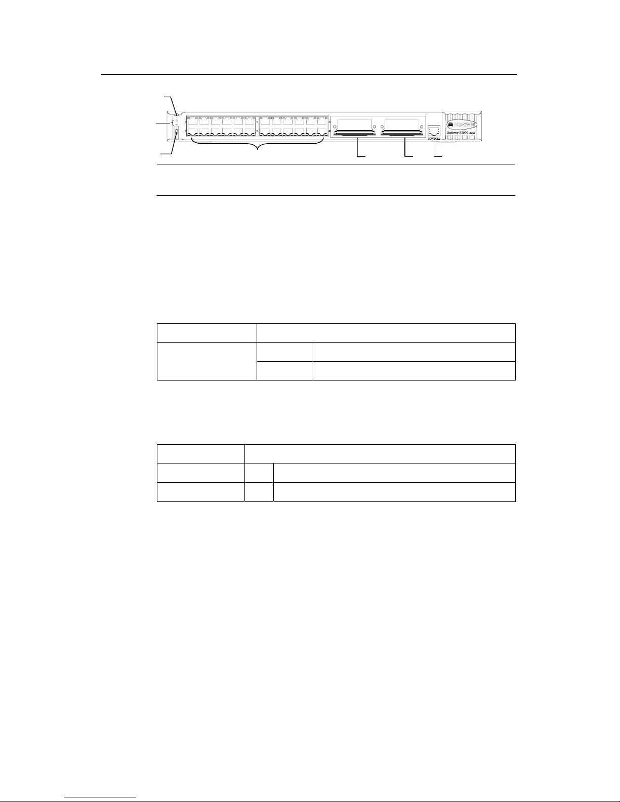
1.2.1 Front Panel
I. Front panel
S3026C-PWR has on its front panel a power LED (PWR), two port status mode
LEDs (A/L, D/S), a mode button, 24 fixed 10/100Base-TX ports (with two LEDs, left
one in yellow and right one in green, for each port), two modular slots, a Console
port. See the figure below.
Installation Manual
Quidway S3026C-PWR Ethernet Switch Chapter 1 Product Overview
Huawei Technologies Proprietary
1-2
(2)
(3)
(1)
(5)
(4)
(6)
(7)
(2)
(3)
(1)
(5)
(4)
(6)
(7)
1) Power LED 2) Port status mode LED 3) Mode button
4) 24 fixed 10/100Base-TX ports 5) Module slot 6) Module slot
7) Console port
Figure 1-1 S3026C-PWR front panel
II. LEDs
The following table summaries the LEDs on the front panel of S3026C-PWR.
z Power LED
Table 1-1 Power LED of S3026C-PWR
LED Status
ON The switch is powered on and operates normally.
Power LED (PWR)
OFF The switch is not powered on.
z Port status mode LEDs
Table 1-2 Port status mode LEDs
LED Status
A/L (Active/Link) ON You can read the active/link status of the ports from the LED.
P/S (Powered/Speed) ON You can read the powered/speed status of the ports from the LED.
z 10/100Base-TX port status LEDs

Installation Manual
Quidway S3026C-PWR Ethernet Switch Chapter 1 Product Overview
Huawei Technologies Proprietary
1-3
Table 1-3 10/100Base-TX port status LEDs of S3026C-PWR
Note LED Status
Yellow
flashing
The port is active and packets are being
transmitted/received on it.
Left
OFF
The port is active and no packets are being
transmitted/received on it.
Green The link on the port is UP (correctly connected).
A/L
Right
OFF
The link on the port is DOWN (no connection) or link
error occurs.
Yellow The port is supplying power for a remote PD device.
Left
OFF
The port does not supply power for a remote PD
device.
Green The port runs at the rate of 100 Mbps.
You can
change the
mode of
10/100Base-TX
ports by
pressing the
mode button.
P/S
Right
OFF The port runs at the rate of 10 Mbps.
Note:
z Through the mode button, you can change status mode of 10/100Base-TX port. The LED in ON
status indicates which status you choose to observe. For example, if you wish to view the link
status of a port, you can choose the A/L LEDs. Through reading the status of port LEDs, you can
know the link status of the port.
z After the switch is initialized, the A/L LED is ON. You can press the mode button to choose the P/S
LED. The switch restores to the A/L LED 45 seconds after you press the mode button.
z You can also determine the power supply mode by pressing the mode button. When the A/L LED
is ON, the switch supply power and detection for the PD device using the data wires (default
mode); when the P/S LED is ON, the switch supply power and detection for the PD device using
the idle wires.
z Modular port LEDs
Table 1-4 Modular port LEDs of S3026C-PWR
LED Status
OFF The link is DOWN on the port.
LNK/LINK
ON The link is UP on the port.
OFF No packets are being transmitted/received on the port.
ACT
Flashing Packets are being transmitted/received on the port.

Installation Manual
Quidway S3026C-PWR Ethernet Switch Chapter 1 Product Overview
Huawei Technologies Proprietary
1-4
III. Fixed 10/100Base-TX ports
Table 1-5 Attributes of 10/100Base-TX ports on S3026C-PWR
Attribute Description
Connector RJ-45
Port number 24
Operational mode
10M half/full duplex
100M half/full duplex
MDI/MDI-X auto-sensing
Standard supported IEEE 802.3u
Transmission cable and maximum transmission distance Category-5 twisted pair cable (100m)
IV. Console port
S3026C-PWR provides an asynchronous EIA/TIA 232-compliant Console port.
Through this port, you can configure locally or remotely the switch.
Table 1-6 Attributes of Console port
Attribute Description
Connector RJ-45
Standard supported Asynchronous EIA/TIA-232
Baudrate 9600 baud (default)
Function
Connects an ASCII terminal
Connects the serial port of a local terminal (which can be a PC) or a remote
terminal (through a pair of Modems) and runs terminal emulation program on
the terminal.
1.2.2 Rear Panel
I. Rear panel
S3026C-PWR has AC input socket, grounding screw, and redundant power socket
on its rear panel. See the figure below.

Installation Manual
Quidway S3026C-PWR Ethernet Switch Chapter 1 Product Overview
Huawei Technologies Proprietary
1-5
冗余
电
源
接
地
交流
电
源
冗余
电
源
接
地
交流
电
源
冗余
电
源
接
地
交流
电
源
冗余
电
源
接
地
交流
电
源
(1)
(2)
(3)
1) AC input 2) Grounding screw 3) Redundant power
Figure 1-2 S3026C-PWR rear panel
II. AC input specifications
Rated voltage range: 100-240V a.c., 50/60Hz
Maximum tolerance: 90-264V a.c., 50/60Hz
1.2.3 Optional Modules
z Single-port 1000Base-LX module
z Single-port 1000Base-SX module
z Single-port 1000Base-T module
z Single-port Gigabit long-haul optical module
z Single-port Gigabit medium-haul optical module
z Single-port Gigabit stack module
z Single-port 100 Mbps single mode optical module (1310nm,15km,SC)
z Single-port 100 Mbps multimode optical module (1310nm,2km,SC)
z Single-port 100 Mbps single mode optical module (1310nm,40km,SC)
z Single-port 100 Mbps SFP module (configurable together with 2km, 15km,
40km and 80km SPF modules)
z Single-port Gigabit GBIC module (configurable together with multimode GBIC
module, single mode 10km, 40km, 70km, 100km GBIC modules, 30m GBIC
Gigabit HSSDC unit and GBIC electrical module)
1.2.4 Remote Power Supply
S3026C-PWR supports power over Ethernet (PoE) feature, that is, it can supply
-48V DC power for the PD devices (IP phone, WLAN AP and Network camera for
example) using twisted pair cables.
z As power sourcing equipment (PSE), S3026C-PWR supports IEEE802.3af
power supply standard.
z S3026C-PWR can transfer data and power current in concurrent way using the
data wires (1, 3, 2 and 6) of category-3/-5 twisted pair cable, or in separate way,
transfer data using the data wires (1, 3, 2 and 6) of category-3/-5 twisted pair

Installation Manual
Quidway S3026C-PWR Ethernet Switch Chapter 1 Product Overview
Huawei Technologies Proprietary
1-6
cable and supply power using its idle wires (4, 5, 7 and 8). You can determine
your own pattern either through appropriate commands or just pressing the
mode button.
z S3026C-PWR can provide power supply for up to 24 downlinked switching
devices, with maximum distance of 100m.
z Each Ethernet port provides a maximum power of 15.4 W for the connected
device.
z S3026C-PWR can provide a total power of 160W for connected switching
devices. It determines whether to supply power for another device based on
this total value and the currently working power.
Note:
z The remote PD devices may choose to accept the power supply from S3026C-PWR as the only
power input.
z If a remote PD device already has its own working power supply, the power supply from
S3026C-PWR can serve as the redundant one.
1.3 Technical Specifications
Table 1-7 Technical specifications of S3026C-PWR
Item S3026C-PWR
Dimensions (W × H × D) 436mm × 42mm× 360mm
Weight 5kg
Fixed port 24 fixed 10/100 Mbps RJ-45 electrical ports
Console port One
Expansion slot Two

Installation Manual
Quidway S3026C-PWR Ethernet Switch Chapter 1 Product Overview
Huawei Technologies Proprietary
1-7
Item S3026C-PWR
Extended module type
Single-port 1000Base-LX module
Single-port 1000Base-SX module
Single-port 1000Base-T module
Single-port Gigabit long-haul optical module
Single-port Gigabit medium-haul optical module
Single-port Gigabit stack module
Single-port 100 Mbps multimode optical module
Single-port 100 Mbps single mode optical module
Single-port 100 Mbps single mode medium-haul optical module
Single-port 100 Mbps SFP module (configurable together with
2km, 15km, and 40km SPF modules)
Single-port Gigabit GBIC module (configurable together with
multimode GBIC module, single mode 10km, 40km, 70km GBIC
modules, 30m GBIC Gigabit HSSDC module and GBIC electrical
module)
1000Base-T:
(rate auto-sensing
between
10/100/1000 Mbps)
10Base-T: Category-3/4/5 non-shielded
twisted pair cable with a maximum
transmission distance of 100m
100/1000Base-T: Category-5 shielded
twisted pair cable with a maximum
transmission distance of 100m
100Base-FX
multimode
62.5/125 µm multimode fiber with a
maximum transmission distance of 2km
100Base-FX single
mode
9/125 µm single mode fiber with a
maximum transmission distance of 15km
100Base-FX single
mode medium-haul:
9/125mm single mode medium-haul fiber
with a maximum transmission distance of
40km
1000Base-LX
9/125 µm single mode fiber with a
maximum transmission distance of 10km
1000Base-SX
62.5/125 µm multimode fiber with a
maximum transmission distance of 220m
50/125 µm multimode fiber with a
maximum transmission distance of 500m
1000Base-ZX
long-haul
9/125 µm single mode fiber with a
maximum transmission distance of 70km
1000Base-LX GL
medium-haul
9/125 µm single mode fiber with a
maximum transmission distance of 40km
Transmission cable and
maximum transmission
distance
Gigabit stack
Special stack cable with a fixed length of
1m

Installation Manual
Quidway S3026C-PWR Ethernet Switch Chapter 1 Product Overview
Huawei Technologies Proprietary
1-8
Item S3026C-PWR
Gigabit GBIC
62.5/125 µm single mode fiber with a
maximum transmission distance of 220m
50/125 µm single mode fiber with a
maximum transmission distance of 500m
9/125 µm single mode fiber with a
maximum transmission distance of 10km
9/125 µm single mode fiber with a
maximum transmission distance of 30km
9/125 µm single mode fiber with a
maximum transmission distance of 40km
9/125 µm single mode fiber with a
maximum transmission distance of 70km
9/125 µm single mode fiber with a
maximum transmission distance of 100km
Category-5 shielded twisted pair cable with
a maximum transmission distance of 100m
HSSDC port-specific cable with a
maximum transmission distance of 30m
100 Mbps SFP
62.5/125 µm single mode fiber with a
maximum transmission distance of 2km
9/125 µm single mode fiber with a
maximum transmission distance of 15km
9/125 µm single mode optical fiber with a
maximum transmission distance of 40km
9/125 µm single mode optical fiber with a
maximum transmission distance of 80km
Input voltage AC input
Maximum tolerance: 90-264V a.c., 50/60Hz
Rated voltage range: 100-240V a.c.,
50/60Hz
Power consumption (full load) 225W
Operating temperature
0 to 45°C
Operating humidity
(non-condensing)
10% to 90%

Installation Manual
Quidway S3026C-PWR Ethernet Switch Chapter 2 Installation Preparation
Chapter 2 Installation Preparation
2.1 Precautions
To avoid any device impairment and bodily injury because of improper use, please
follow the precautions listed below:
z Before cleaning the switch, please unplug the switch connector first. Do not
clean the switch with wet cloth or with liquid.
z Do not place the switch near water or any damp area. Prevent water or
moisture from entering the switch chassis.
z Do not place the switch on the unstable cases or desks, as the switch might be
damaged severely in case of a fall.
z Ensure proper ventilation of the room and keep the switch ventilation hole free
of obstruction.
z The switch can operate normally under correct voltage input. Make sure that
the operating voltage is consistent with that labeled on the switch.
z Do not open the chassis while the switch is in operation to protect the safe of
the operator and the switch.
z Before changing I/O board, wear ESD-protective gloves for fear of damaging
the board with ESD.
2.2 Requirements on Environment
S3026C-PWR must be used indoors. The following conditions must be met
regardless of whether you install the switch in a 19-inch standard cabinet or install it
directly on a tabletop.
z Make sure that enough room is left for the air-intake hole and the ventilation
hole of the switch, so that the heat dissipation of the switch chassis can be
guaranteed.
z Make sure that the ventilation and heat dissipation systems of the cabinet and
the tabletop are good.
z Make sure that the cabinet and the tabletop are stable enough to bear the
weight of the switch and the accessories.
z Make sure that the cabinet and the tabletop are well grounded.
To ensure normal operation and to prolong the life span of the switch, the following
requirements on the installation site must also be satisfied.
Huawei Technologies Proprietary
2-1

Installation Manual
Quidway S3026C-PWR Ethernet Switch Chapter 2 Installation Preparation
2.2.1 Temperature/Humidity Requirements
To ensure the normal operation and service life of a switch, the user needs to
maintain the temperature and the humidity of the equipment room at a certain level.
If the humidity level in the equipment room is too high for a long time, it will lead to
bad insulation of the insulating material or even leakage. Sometimes, the
mechanical performance, changes of material, the rustiness and corrosion of some
metal parts are also likely to occur. If the relative humidity is too low, the captive
screws may become loose due to the shrinking of insulation washers. Meanwhile,
electrostatic phenomenon is likely to happen in the dry weather environment, which
will jeopardize the CMOS circuit of the switch. The higher the temperature, the
greater the damage to the switch will be. High temperature for a long time will speed
up the aging process of the insulation materials, greatly lower the reliability of the
switch and therefore affect its life span seriously.
2.2.2 Cleanness Requirements
Dust will hazard safe operation of the equipment. Falling on the equipment, it may
cause electrostatic adsorption, and hence result in poor contact of the metal
connectors or connection points. This is more likely to happen when the relative
indoor humidity is low, which will not only shorten the device's service life, but also
incur communication failures. The requirements on dust content and particle
diameter in the equipment room are shown in the following table:
Table 2-1 Requirements on dust content in an equipment room
Mechanically activated
material
Unit Content
Dust particle Partical/m³
≤
3 × 10
4
(with dust invisible on the table
top in three consecutive days)
Note: Diameter of dust particles ≥ 5 µm
Besides the requirements on dust, rigorous requirements are also set on the air
content of salts, acids, and sulfides in an equipment room. These harmful gases will
accelerate metal corrosion and aging process of certain parts. The equipment room
should be protected from harmful gases such as SO
2
, H2S, NO2, NH3 and Cl2, the
value limits of which are shown in the following Table.
Huawei Technologies Proprietary
2-2

Installation Manual
Quidway S3026C-PWR Ethernet Switch Chapter 2 Installation Preparation
Table 2-2 Limits on harmful gas contents in an equipment room
Gas Maximum (mg/m
3
)
SO
2
0.2
H2S 0.006
NH
3
0.05
Cl
2
0.01
2.2.3 Anti-interference Requirements
A switch in use may be affected by the interference sources outside the system in a
way of capacitance coupling, inductance coupling, radiation of electromagnetic wave,
public impedance coupling (including the grounding system) or conducting line
(power cord, signaling line and transmission line, etc.). Therefore, the following
should be considered:
z If AC supply system is TN system, AC power socket should be a monophase
three-wire power socket with Protection Earth (PE). Thereby, the filter circuit in
the equipment can effectively filter interference from the power supply system.
z Keep the switch far away from radio launcher, radar launcher, and
high-frequency devices working in high current.
z Adopt the measure of electromagnetic shielding if necessary. For example, you
can adopt shielded interface cable.
z Interface cable must be run indoors, and outdoor cabling is not permitted,
otherwise, over-voltage and over-current may damage the device.
2.2.4 Laser Usage Security
S3026C-PWR is the class I laser device.
In operating status, it is prohibited to stare into the open optical interface because
the laser being transmitted through the optical fiber will produce a small beam of
light, because it has very high power density, when a beam of light enters the eye,
retina may be burned.
Caution:
Looking into the laser beam inside the fiber shall hurt your eyes.
Huawei Technologies Proprietary
2-3

Installation Manual
Quidway S3026C-PWR Ethernet Switch Chapter 2 Installation Preparation
2.3 Tools and Devices Required in Installation
1) Tools required
z Phillips screwdriver
z Flat-blade screwdriver
z ESD-preventive wrist strap
2) Cables
z Power cord
z Console cable
z Ground wire
3) Other devices
z Configuration terminal (or a PC)
Caution:
Installation tools are not delivered with S3026C-PWR, so you have to prepare them by yourself.
Huawei Technologies Proprietary
2-4
 Loading...