

Page 1

Operation Manual - STP
Quidway S3000 Series Ethernet Switches Table of Contents
i
Table of Contents
Chapter 1 RSTP Configuration..................................................................................................... 1-1
1.1 STP Overview....................................................................................................................1-1
1.1.1 Function of STP.......................................................................................................1-1
1.1.2 Implement STP........................................................................................................1-1
1.1.3 Implement RSTP on Ethernet Switch......................................................................1-7
1.2 Configure RSTP................................................................................................................. 1-7
1.2.1 Enable/Disable RSTP on a Switch.......................................................................... 1-8
1.2.2 Enable/Disable RSTP on a Port.............................................................................. 1-8
1.2.3 Configure RSTP Operating Mode........................................................................... 1-9
1.2.4 Set Priority of a Specified Bridge ............................................................................1-9
1.2.5 Specify the Switch as Primary or Secondary Root Switch.................................... 1-10
1.2.6 Set Forward Delay of a Specified Bridge.............................................................. 1-11
1.2.7 Set Hello Time of the Specified Bridge .................................................................1-12
1.2.8 Set Max Age of the Specified Bridge....................................................................1-12
1.2.9 Set Timeout Factor of the Bridge.......................................................................... 1-13
1.2.10 Set the Maximum Transmission Speed of the Specified Port............................. 1-13
1.2.11 Set Specified Port to be an EdgePort.................................................................1-14
1.2.12 Set Path Cost of the Specified Port ....................................................................1-14
1.2.13 Set the Priority of a Specified Port...................................................................... 1-15
1.2.14 Configure a Specified Port to be Connected to Point-to-Point Link.................... 1-15
1.2.15 Set mCheck of the Specified Port....................................................................... 1-16
1.2.16 Configure the Switch Security Function.............................................................. 1-17
1.3 Display and Debug RSTP................................................................................................1-18
1.4 RSTP Configuration Example.......................................................................................... 1-19
Chapter 2 MSTP Region-configuration ....................................................................................... 2-1
2.1 MSTP Overview.................................................................................................................2-1
2.1.1 MSTP Concepts...................................................................................................... 2-1
2.1.2 MSTP Principles...................................................................................................... 2-4
2.2 Configure MSTP ..............................................................................................................2-10
2.2.1 Configure the MST Region for a Switch................................................................ 2-11
2.2.2 Specify the Switch as Primary or Secondary Root Switch.................................... 2-13
2.2.3 Configure the MSTP Running Mode..................................................................... 2-14
2.2.4 Configure the Bridge Priority for a Switch............................................................. 2-15
2.2.5 Configure the Max Hops in an MST Region ......................................................... 2-15
2.2.6 Configure the Switching Network Diameter..........................................................2-16
2.2.7 Configure the Time Parameters of a Switch.........................................................2-16
2.2.8 Configure the Max Transmission Speed on a Port............................................... 2-18
Page 2

Operation Manual - STP
Quidway S3000 Series Ethernet Switches Table of Contents
ii
2.2.9 Configure a Port as an Edge Port......................................................................... 2-19
2.2.10 Configure the Path Cost of a Port....................................................................... 2-20
2.2.11 Configure the Priority of a Port............................................................................ 2-21
2.2.12 Configure the Port (not) to Connect with the Point-to-Point Link........................ 2-22
2.2.13 Configure the mCheck Variable of a Port ........................................................... 2-24
2.2.14 Configure the Switch Security Function.............................................................. 2-25
2.2.15 Enable MSTP on the Device...............................................................................2-26
2.2.16 Enable/Disable MSTP on a Port.........................................................................2-27
2.3 Display and Debug MSTP ............................................................................................... 2-28
Page 3

Operation Manual - STP
Quidway S3000 Series Ethernet Switches Chapter 1 RSTP Configuration
1-1
Chapter 1 RSTP Configuration
1.1 STP Overview
1.1.1 Function of STP
Spanning Tree Protocol ( STP ) is applied in loop network to block some undesirable
redundant paths with certain algorithms and prune the network into a loop-free tree,
thereby avoiding the proliferation and infinite cycling of the packet in the loop network.
1.1.2 Implement STP
The fundamental of STP is that the switches exchange a special ki nd of protocol packet
(which is called configuration Bridge Protocol Data Units, or BPDU, in IEEE 802.1D) to
decide the topology of the network. The configuration BPDU contains the information
enough to ensure the switches to compute the spanning tree.
The configuration BPDU mainly contains the following information:
1) The root ID consisting of root priority and MAC address
2) The cost of the shortest path to the root
3) Designated switch ID consisting of designated switch priority and MAC address
4) Designated port ID consisting of port priority and port number
5) The age of the configuration BPDU: MessageAge
6) The maximum age of the configuration BPDU: MaxAge
7) Configuration BPDU interval: HelloTime
8) Forward delay of the port: ForwardDelay.
What are the designated switch and designated port?
Page 4
Operation Manual - STP
Quidway S3000 Series Ethernet Switches Chapter 1 RSTP Configuration
1-2
Switch A
Switch C
Switch B
CP2
BP2
CP1
BP1
AP2AP1
LAN
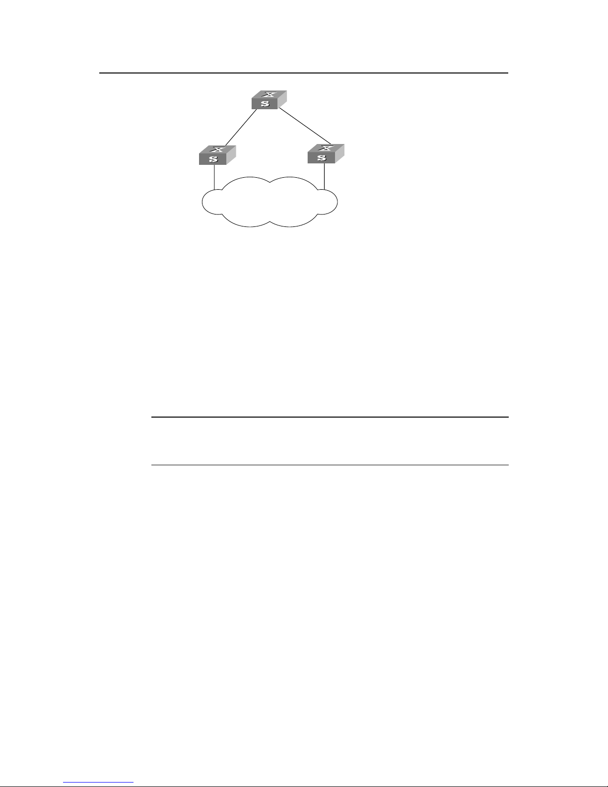
Figure1-1 Designated switch and designated port
For a switch, the designated switch is a switch in charge of forwarding packets to the
local switch via a port called the designated port accordingly . For a LAN, the designated
switch is a switch that in charge of forwarding packets to the network segment via a port
called the designated port accordingly . As illustrated in the figu re1-1, Switch A forwards
data to Switch B via the port AP1. So to Switch B, the designated switch is Switch A and
the designated port is AP1. Also in the figure above, Switch B and Switch C are
connected to the LAN and Switch B forwards packets to LAN. So the designated switch
of LAN is Switch B and the designated port is BP2.
Note:
AP1, AP2, BP1, BP2, CP1 and CP2 respectively delegate the ports of Switch A, Switch B and Switch C.
z The specific calculation process of STP algorithm.
The following example illustrates the calculation process of STP.
The figure1-2 below illustrates the network.
Page 5
Operation Manual - STP
Quidway S3000 Series Ethernet Switches Chapter 1 RSTP Configuration
1-3
Switch A
with priority 0
Switch C
with priority 2
Switch B
with priority 1
CP2
BP2
CP1
BP1
AP2
AP1
4
10
5
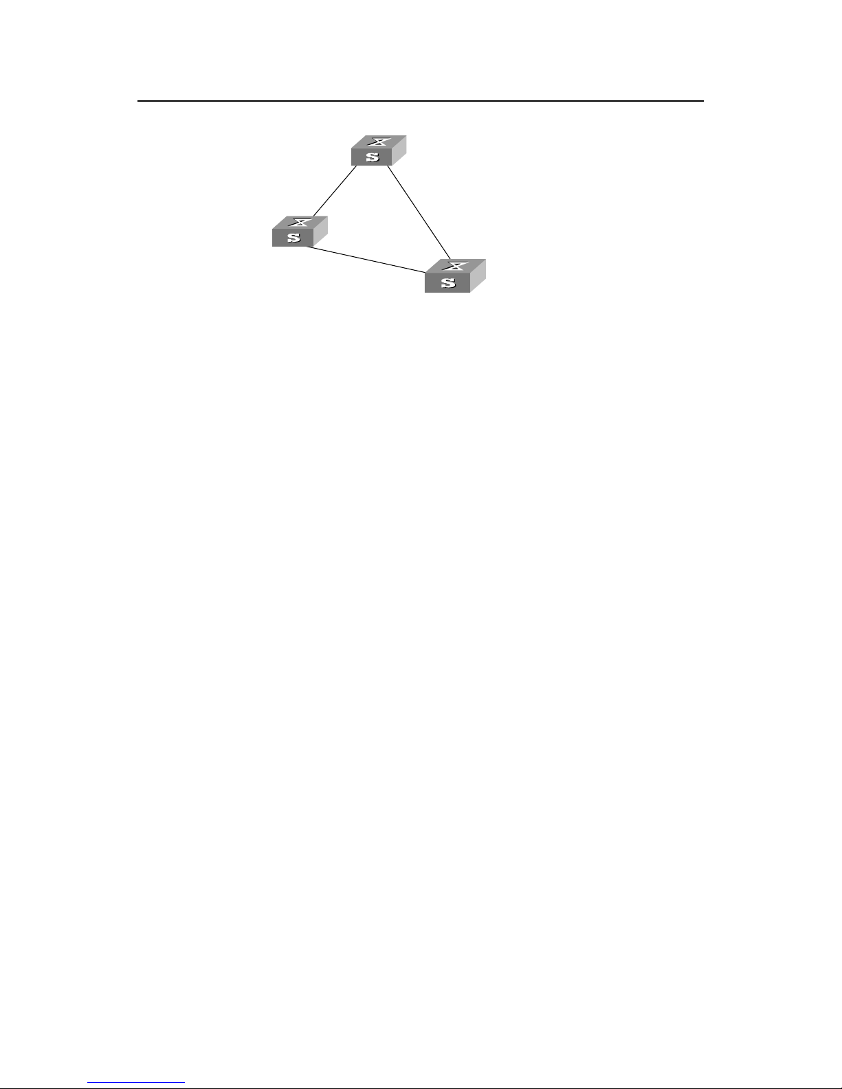
Figure1-2 Ethernet switch networking
To facilitate the descriptions, only the first four parts of the configuration BPDU are
described in the example. They are root ID (expressed as Ethernet switch priority), path
cost to the root, designated switch ID (expressed as Ethernet switch priority) and the
designated port ID (expressed as the port number). As illustrated in the figure above,
the priorities of Switch A, B and C are 0, 1 and 2 and the p ath costs of their links are 5,
10 and 4 respectively.
9) Initial state
When initialized, each port of the switches will generate the configuration BPDU taking
itself as the root with a root path cost as 0, designated switch IDs as their own switch
IDs and the designated ports as their ports.
Switch A:
Configuration BPDU of AP1: {0, 0, 0, AP1}
Configuration BPDU of AP2: {0, 0, 0, AP2}
Switch B:
Configuration BPDU of BP1: {1, 0, 1, BP1}
Configuration BPDU of BP2: {1, 0, 1, BP2}
Switch C:
Configuration BPDU of CP2: {2, 0, 2, CP2}
Configuration BPDU of CP1: {2, 0, 2, CP1}
10) Select the optimum configuration BPDU
Every switch transmits its configuration BPDU to others. When a port receives a
configuration BPDU with a lower priority than that of its own, it will discard the message
and keep the local BPDU unchanged. When a higher-priority configuration BPDU is
Page 6

Operation Manual - STP
Quidway S3000 Series Ethernet Switches Chapter 1 RSTP Configuration
1-4
received, the local BPDU is updated. And the optimum configuration BPDU will be
elected through comparing the configuration BPDUs of all the ports.
The comparison rules are:
z The configuration BPDU with a smaller root ID has a higher priority
z f the root IDs are the same, perform the comparison based on root path costs. The
cost comparison is as follows: the path cost to the root recorded in the
configuration BPDU plus the corresponding path cost of the local port is set as S,
the configuration BPDU with a smaller S has a higher priority.
z If the costs of path to the root are also the same, compare in sequence the
designated switch ID, designated port ID and the ID of the port via which the
configuration BPDU was received.
In summary, we assume that the optimum BPDU can be selected through root ID
comparison in the example.
11) Specify the root port, block the redundancy link and update the configuration
BPDU of the designated port.
The port receiving the optimum configuration BPDU is designated to be the root port,
whose configuration BPDU remains the same. Any other port, whose configuration
BPDU has been updated in the step Select the optimum configuration BPDU, will be
blocked and will not forward any data, in addition, it will only receive but not transmit
BPDU and its BPDU remains the same. The port, wh ose BPDU has not been updated
in the step Select the optimum configuration BPDU will be the designated port. Its
configuration BPDU will be modified as follows: substituting the root ID with the root ID
in the configuration BPDU of the root port, the cost of path to root with the value made
by the root path cost plus the path cost corresponding to the root port, the designated
switch ID with the local switch ID and the designated port ID with the local port ID.
The comparison process of each switch is as follows.
Switch A:
AP1 receives the configuration BPDU from Switch B and finds out that the local
configuration BPDU priority is higher than that of the received one, so it discards the
received configuration BPDU. The configuration BPDU is processed on the AP2 in a
similar way. Thus Switch A finds itself the root and designated switch in the
configuration BPDU of every port; it regards itself as the root, retains the configuration
BPDU of each port and transmits configuration BPDU to others regularly thereaf ter. By
now, the configuration BPDUs of the two ports are as follows:
Configuration BPDU of AP1: {0, 0, 0, AP1}.
Configuration BPDU of AP2: {0, 0, 0, AP2}.
Switch B:
Page 7

Operation Manual - STP
Quidway S3000 Series Ethernet Switches Chapter 1 RSTP Configuration
1-5
BP1 receives the configuration BPDU from Switch A and finds that the received BPDU
has a higher priority than the local one, so it updates its configuration BPDU.
BP2 receives the configuration BPDU from Switch C and finds that the local BPDU
priority is higher than that of the received one, so it discards the received BPDU.
By now the configuration BPDUs of each port are as follows: Configuration BPDU of
BP1: {0, 0, 0, AP1}, Configuration BPDU of BP2: {1, 0, 1, BP2}.
Switch B compares the configuration BPDUs of the ports and select s the BP1 BPDU as
the optimum one. Thus BP1 is elected as the root port and the configuration BPDUs of
Switch B ports are updated as follows.
The configuration BPDU of the root port BP1 retains a s {0, 0, 0, BP1}. BP2 updates root
ID with that in the optimum configuration BPDU, the path cost to root with 5, sets the
designated switch as the local switch ID and the designated port ID as the local port ID.
Thus the configuration BPDU becomes {0, 5, 1, BP2}.
Then all the designated ports of Switch B transmit the configuration BPDUs regularly.
Switch C:
CP2 receives from the BP2 of Switch B the configuration BPDU {1, 0, 1, BP2} that has
not been updated and then the updating process is launched. {1, 0, 1, BP2}.
CP1 receives the configuration BPDU {0, 0, 0, AP2} from Switch A and Switch C
launches the updating. The configuration BPDU is updated as {0, 0, 0, AP2}.
By comparison, CP1 configuration BPDU is elected as the optimum one. The CP1 is
thus specified as the root port with no modifications made on its configuration BPDU.
However, CP2 will be blocked and its BPDU also remains same, but it will not receive
the data (excluding the STP packet) forwarded from Switch B until spanning tree
calculation is launched again by some new events. For example, the link from Switch B
to C is down or the port receives any better configuration BPDU.
CP2 will receive the updated configuration BPDU, {0, 5, 1, BP2}, from Switch B. Since
this configuration BPDU is better then the old one, the old BPDU will be updated to {0,
5, 1, BP2}.
Meanwhile, CP1 receives the configuration BPDU from Switch A but its configuration
BPDU will not be updated and retain {0, 0, 0, AP2}.
By comparison, the configuration BPDU of CP2 is elected as the optimum one, CP2 is
elected as the root port, whose BPDU will not change, while CP1 will be blocked and
retain its BPDU, but it will not receive the data forwarded from Switch A until spanning
tree calculation is triggered again by some changes. For example, the link from Switch
B to C as down.
Page 8
Operation Manual - STP
Quidway S3000 Series Ethernet Switches Chapter 1 RSTP Configuration
1-6
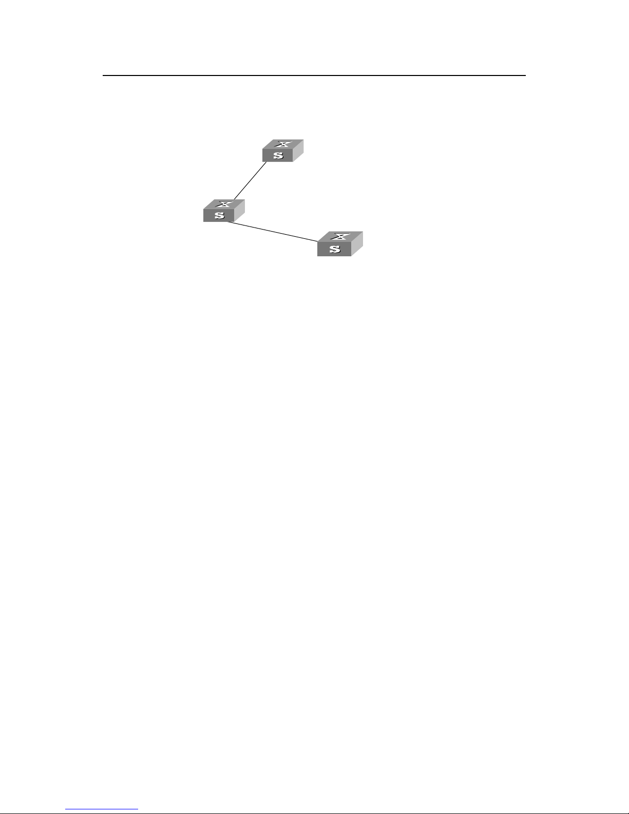
Thus the spanning tree is stabilized. The tree with the root Switch A is illustrated in the
figure1-3 below.
Switch A
with priority 0
Switch C
with priority 2
Switch B
with priority 1
CP2
BP2
BP1
AP1
4
5
Figure1-3 The final stabilized spanning tree
To facilitate the descriptions, the description of the example is simplified. For example,
the root ID and the designated switch ID in actual calculation should comprise both
switch priority and switch MAC address. Designated port ID should comprise port
priority and port MAC address. In the updating process of a configuration BPDU, other
configuration BPDUs besides the first four items will make modifications according to
certain rules. The basic calculation process is de scribed below:
z Configuration BPDU forwarding mechanism in STP:
Upon the initiation of the network, all the switches regard themselves as the roots. The
designated ports send the configuration BPDUs of local ports at a regular interval of
HelloTime. If it is the root port that receives the configuration BPDU, the switch will
enable a timer to time the configuration BPDU as well as increase MessageAge carried
in the configuration BPDU by certain rules. If a path goes wrong, the root port on this
path will not receive configuration BPDUs any more and the old configuration BPDUs
will be discarded due to timeout. Hence, recalculation of the spanning tree will be
initiated to generate a new path to replace the failed one and thus restore the network
connectivity.
However, the new configuration BPDU as now recalculated will not be propagated
throughout the network right away , so the old root ports and design ated ports that have
not detected the topology change will still forward the data through the old path. If the
new root port and designated port begin to forward data immediately after they are
elected, an occasional loop may still occur . In RSTP, a transitional state mechanism is
thus adopted to ensure the new configuration BPDU has been propagated throughout
the network before the root port and designated port begin to send data again. That is,
the root port and designated port should undergo a transitional state for a period of
Forward Delay before they enter the forwarding state.
Page 9

Operation Manual - STP
Quidway S3000 Series Ethernet Switches Chapter 1 RSTP Configuration
1-7
1.1.3 Implement RSTP on Ethernet Switch
The Ethernet Switch implements the Rapid Spanning Tree Protocol (RSTP), i.e., the
enhancement of STP. The Forward Delay for the root ports and designated ports to
enter forwarding state is greatly reduced in certain conditions, thereby shortening the
time period for stabilizing the network topology.
To achieve the rapid transition of the root port state, the following requirement should
be met: The old root port on this switch has stopped data forwarding and the
designated port in the upstream has begun forwarding data.
The conditions for rapid state transition of the designated port are:
z The port is an Edge port that does not connect with any switch dire ctly or indirectly.
If the designated port is an edge port, it can switch to forwarding state directly
without immediately forwarding data.
z The port is connected with the point-to-point link, that is, it is the master port in
aggregation ports or full duplex port. It is feasible to configure a point-to-point
connection. However, errors may occur and therefore this configuration is not
recommended. If the designated port is connected with the point-to-point link, it
can enter the forwarding state right after handshaking with the do wnstream switch
and receiving the response.
The switch that uses RSTP is compatible with the one using STP. Both protocol packets
can be identified by the switch running RSTP and used in spanni ng tree calculation.
Note:
RSTP is the protocol of single spanning tree. A switching network only has one spanning tree. To
guarantee the normal communication inside a VLAN, the devices of a VLAN shall have routes to one
another on the Spanning Tree, otherwise, the communication inside the VLAN will be affected if some links
inside a VLAN are blocked.
For some VLAN that cannot be arranged along the spanning tree paths for some special requirements,
you have to disable RSTP on the switch port corresponding to the VLAN.
1.2 Configure RSTP
RSTP configuration includes:
z Enable/Disable RSTP on the switch
z Enable/Disable RSTP on the port
z Configure RSTP Operating Mode
z Set priority of a specified bridge
Page 10

Operation Manual - STP
Quidway S3000 Series Ethernet Switches Chapter 1 RSTP Configuration
1-8
z Set Forward Delay of a specified bridge
z Set Hello Time of the specified bridge
z Set Max Age of the specified bridge
z Set the maximum transmission speed of the specified port
z Set specified port as the EdgePort
z Set path cost of the specified port
z Set the priority of a specified port
z Configure a specified port to be connected to a point-to-point link
z Set mCheck of the specified port
Among the above-mentioned tasks, only the steps of enabling STP on the switch and
enabling STP on the port are required. For other tasks, if you do not configu re them, the
system will use the default settings.
Before enabling spanning tree, relative parameters of Ethernet port or the device can
be configured. After disabling the span ning tree, these configuration parameters will be
reserved and becoming functional after enabling the spanning tree again.
1.2.1 Enable/Disable RSTP on a Switch
You can use the following command to enable RSTP on the switch.
Perform the following configurations in system view .
Table1-1 Enable/Disable RSTP on a device
Operation Command
Enable/Disable RSTP on a device stp { enable | disable }
Restore RSTP to the default value undo stp
Only after the RSTP is enabled on the switch can other configurations take effect.
Note that some network resource will be occupied after RSTP is e nabled.
By default, RSTP is disabled.
1.2.2 Enable/Disable RSTP on a Port
Y ou can use the following command to e nable/disable the RSTP on the de signated port.
To flexibly control the RSTP operations, after RSTP is enabled on the Ethernet po rts of
the switch, it can be disabled again to forbid the ports to p articipate in the span ning tree
calculation.
Perform the following configurations in Ethernet port view.
Page 11

Operation Manual - STP
Quidway S3000 Series Ethernet Switches Chapter 1 RSTP Configuration
1-9
Table1-2 Enable/Disable RSTP on a port
Operation Command
Enable RSTP on a specified port stp enable
Disable RSTP on a specified port stp disable
Note that the redundancy route may be generated after RSTP is disabled on the
Ethernet port.
By default, RSTP on all the ports will be enabled after it is enabled on the switch.
1.2.3 Configure RSTP Operating Mode
RSTP is executable in RSTP mode or STP-compatible mode. RSTP mode is applied
when all the network devices provided for executing RSTP, while the STP-compatible
mode is applied when both STP and RSTP are execu table on the network.
You can use the following command to set the RSTP operating mode.
Perform the following configurations in system view .
Table1-3 Set RSTP operating mode
Operation Command
Configure to run RSTP in STP-compatible/RSTP mode stp mode { stp | rstp }
Restore the default RSTP mode undo stp mode
Normally , if there is a bridge provided to execute STP in the switching network, the port
(in the switch running RSTP), which connects to another port (in the switch for
executing STP), can automatically switch to STP compatible mode from RSTP mode.
By default, RSTP runs in RSTP mode.
1.2.4 Set Priority of a Specified Bridge
Whether a bridge can be selected as the “root” of the spanning tree depends on its
priority . By assignin g a lower pri ority, a bridge can be artificially specified as the root of
the spanning tree.
You can use the following command to configure the priority of a specified bridge.
Perform the following configurations in system view .
Page 12

Operation Manual - STP
Quidway S3000 Series Ethernet Switches Chapter 1 RSTP Configuration
1-10
Table1-4 Set priority of a specified bridge
Operation Command
Set priority of a specified bridge stp priority bridge-priority
Restore the default priority of specified bridge undo stp priority
Note that if the priorities of all the bridges in the switching network are the same, the
bridge with the smallest MAC address will be selected as the “root”. When RSTP is
enabled, an assignment of a priority to the bridge will lead to recalculation of the
spanning tree.
By default, the priority of the bridge is 32768.
1.2.5 Specify the Switch as Primary or Secondary Root Switch
RSTP can determine the spanning tree root through calculation. You can also specify
the current switch as the root using this command.
You can use the following commands to specify the current switch as the primary or
secondary root of the spanning tree.
Perform the following configuration in system view.
Table1-5 Specify the switch as primary or secondary root switch
Operation Command
Specify the current switch as the primary root switch of the spanning tree. stp root primary
Specify the current switch as the secondary root switch of the spanning tree. stp root secondary
Disqualify the current switch as the primary or secondary root. undo stp root
After a switch is configured as primary root switch or secondary root switch, user can’t
modify the bridge priority of the switch.
A switch can either be a primary or secondary root bridge, but not both of them.
If the primary root of a spanning tree instance is down or powered off, the secondary
root will take its place, unless you configure a new primary root. Of two or more
configured secondary root switches, RSTP selects the one with the smallest MAC
address to take the place of the failed primary root.
Page 13

Operation Manual - STP
Quidway S3000 Series Ethernet Switches Chapter 1 RSTP Configuration
1-11
Note:
To configure a switch as the root of the spanning tree instance, you can specify its priority as 0 or simply
set it as the root, using the command.
It is not necessary to specify two or more roots for an STI. In other words, please do not specify the root for
an STI on two or more switches.
You can configure more than one secondary root for a spanning tree through specifying the secondary STI
root on two or more switches.
Generally, you are recommended to designate one primary root and more than one secondary roots for a
spanning tree.
By default, a switch is neither the primary root nor the secondary root of the spanning
tree.
1.2.6 Set Forward Delay of a Specified Bridge
Link failure will cause recalculation of the spanning tree and change its structure.
However, the newly calculated configuration BPDU cannot be propagated throughout
the network immediately. If the newly selected root port and designated port begin to
forward data frame right away, occasional loop can be caused. Accordingly, the
protocol adopts a state transition mechanism, that is, the root port and the designated
port must undergo a transition state for a period of Forward Delay before they transition
to the forwarding state and resume data frame forwarding. This delay ensures that the
new configuration BPDU has been propagated throughout the network before the dat a
frame forwarding is resumed.
You can use the following command to set the Forward Delay for a specified bridge.
Perform the following configurations in system view .
Table1-6 Set forward delay of a specified bridge
Operation Command
Set Forward Delay of a specified bridge stp timer forward-delay centiseconds
Restore the default Forward Delay of specified bridge undo stp timer forward-delay
Forward Delay of the bridge is related to the diameter of the switching network. As a
rule , the larger the network diameter , the longer the Forward Delay. Note that if the
Forward Delay is configured too short, occasional path redundancy may occur. If the
Forward Delay is configured too long, the restoring of network connection may take a
long time. It is recommended to use the default setting.
By default, the bridge Forward Delay is 15 seconds.
Page 14
Operation Manual - STP
Quidway S3000 Series Ethernet Switches Chapter 1 RSTP Configuration
1-12
1.2.7 Set Hello Time of the Specified Bridge
A bridge transmit s hello pa cket regularly to the adjacen t bridges to check if there is link
failure.
You can use the following command to set the Hello Ti me of a specified bridge.
Perform the following configurations in system view .
Table1-7 Set Hello Time of the specified bridge
Operation Command
Set Hello Time of the specified bridge stp timer hello centiseconds
Restore the default Hello Time of the specified bridge undo stp timer hello
Appropriate Hello Time can ensure that the bridge can detect the link failure in the
network in time without occupying too many network resources. If the Hello Time is too
long it will result in the spanning tree recalculation because the bridge mistakes due to
the frame dropping of the link for link failure. If the Hello T i me is too short, it will result
in frequently sending of configuration BPDUs by the bridge and thus unduly increasing
the switch load and wastes of network resource.
By default, the Hello Time of the bridge is 2 seconds.
1.2.8 Set Max Age of the Specified Bridge
Max Age is a parameter to judge whether the configuration BPDU is “timeout”. Users
can configure it according to the actual network situation.
You can use the following command to set Max Age of a specified b ridg e.
Perform the following configurations in system view .
Table1-8 Set Max Age of the specified bridge
Operation Command
Set Max Age of the specified bridge stp timer max-age centiseconds
Restore the default Max Age of the specified bridge undo stp timer max-age
If the Max Age is too short, it will result in frequent calculation of spanning tree or
misjudge the network congestion as a link fault. On the other hand, too long Max Age
may make the bridge unable to find link failure in time and weaken the network
auto-sensing ability. It is recommended to use the default setting.
By default, the bridge Max Age is 20 seconds.
Page 15

Operation Manual - STP
Quidway S3000 Series Ethernet Switches Chapter 1 RSTP Configuration
1-13
1.2.9 Set Timeout Factor of the Bridge
A bridge transmit s hello pa cket regularly to the adjacen t bridges to check if there is link
failure. Generally, if the switch doesn’t receive the RSTP packets from the upstream
switch for 3 times of hello time, the switch will decide the upstream switch is dead and
will recalculate the topology of the network. Then in steady network, the recalculation
may be caused when the upstream is busy. In this case, user can redefine the timeout
interval to a longer time by define the multiple of hello time.
Y ou can use the follo wing command to set the multiple value of hello time of a sp ecified
bridge.
Perform the following configurations in system view .
Table1-9 Set Timeout Factor of the Bridge
Operation Command
Set the multiple value of hello time of a specified bridge stp timeout-factor number
Restore the default multiple value of hello time undo stp timeout-factor
It is recommended to set 5, 6 or 7 as the value of multiple in the steady network.
By default, the multiple value of hello time of the bridge is 3.
1.2.10 Set the Maximum Transmission Speed of the Specified Port
The maximum transmission speed of Ethernet port is related to its physical state and
network structure. Users can configure it according to the actual network situation.
You can use the following command to set the maximum transmission speed of the
specified port.
Perform the following configurations in Ethernet port view.
Table1-10 Set the maximum transmission speed of the specified port
Operation Command
Set the maximum transmission speed of the specified port stp transit-limit packetnum
Restore the default maximum transmission speed of the
specified port
undo stp transit-limit
If the max transmission speed on a port is too high, there will be too many packets
being transmitted per unit time, which occupies excessive network resources. It is
recommended to use the default setting.
Page 16

Operation Manual - STP
Quidway S3000 Series Ethernet Switches Chapter 1 RSTP Configuration
1-14
By default, the maximum transmission speed is 3 (a counter value without unit) on all
the Ethernet ports of the bridge.
1.2.11 Set Specified Port to be an EdgePort
EdgePort is not connected to any switch directly or indirectly via the connected
network.
You can use the following command to set a specified port as an EdgePort.
Perform the following configurations in Ethernet port view.
Table1-11 Set specified port as the EdgePort
Operation Command
Set a specified port as an EdgePort or a non-EdgePort stp edged-port { enable | disable }
Set the specified port as the non-EdgePort, as defaulted undo stp edged-port
In the process of recalculating the spanning tree, the EdgePort can transfer to the
forwarding state directly and reduce unnecessary transition time. If the current
Ethernet port is not connected with any Ethernet port of other bridges, this port should
be set as an EdgePort. If a specified port connected to a port of any other bridge is
configured as an edge port, RSTP will automatically detect and reconfigure it as a
non-EdgePort.
After the network topology changed, if a configured non-EdgePort changes to an
EdgePort and is not connected to any other port, it is recommende d to configur e it as
an EdgePort manually because RSTP cannot configure a non-EdgePort as an
EdgePort automatically.
Configure the port directly connected to the terminal as an EdgePort, so that the port
can transfer immediately to the forwarding state.
By default, all the Ethernet ports are configured as non-EdgePort.
1.2.12 Set Path Cost of the Specified Port
The path cost of Ethernet port is related to the speed of a link connected to the port.
You can use the following command to set the Path Cost of a specified port.
Perform the following configurations in Ethernet port view.
Page 17

Operation Manual - STP
Quidway S3000 Series Ethernet Switches Chapter 1 RSTP Configuration
1-15
Table1-12 Set path cost of the specified port
Operation Command
Set path cost of the specified port stp cost cost
Restore the default path cost of the specified port undo stp cost
The path cost of Ethernet port is related to its link speed. The higher the link speed is,
the lower the path cost should be configured. RSTP can automatically detect the link
speed on the current Ethernet port and convert it to the corresponding path cost. Note
that configuring path cost of an Ethernet port will cause the recalculation of the
spanning tree. It is recommended to use the default value and let RSTP calculate the
path cost on the current Ethernet port.
By default, the bridge gets the path cost of a port according to the link speed directly.
1.2.13 Set the Priority of a Specified Port
The port priority is an important basis to decide if the port can be a root port. In the
calculation of the spanning tree, the port with the highest priority will be selected a s the
root assuming all other conditions are the same.
You can use the following command to set the priority of a specified port.
Perform the following configurations in Ethernet port view.
Table1-13 Set the priority of a specified port
Operation Command
Set the priority of a specified port stp port priority port-priority
Restore the default priority of the specified port undo stp port priority
By setting the priority of an Ethernet port, you can put a specified Ethernet port into the
final spanning tree. Generally, the lower the value is set, the higher priority the port has
and the more likely it is for this Ethernet port to be included in the spanning tree. If all
the Ethernet ports of the bridge adopt the same priority parameter value, then the
priority of these ports depends on the Ethernet port index number. Note that changing
the priority of Ethernet port will cause recalculation of the spanning tree. You can set
the port priority at the time when setting up the networking requirements.
By default, priorities of all the Ethernet ports are 128.
1.2.14 Configure a Specified Port to be Connected to Point-to-Point Link
Generally, a point-to-point link connects the switches.
Page 18

Operation Manual - STP
Quidway S3000 Series Ethernet Switches Chapter 1 RSTP Configuration
1-16
You can use the following command to configure a specified port to be connected to a
point-to-point link.
Perform the following configurations in Ethernet port view.
Table1-14 Configure a specified port to be connected to a point-to-point link
Operation Command
Configure a specified port to be connected to a point-to-point link stp point-to-point force-true
Configure a specified port not to be connected to a point-to-point
link
stp point-to-point force-false
Configure RSTP to automatically detect if the port is connected to a
point-to-point link.
stp point-to-point auto
Configure the port to be automatically detected if it is connected to
a point-to-point link, as defaulted.
undo stp point-to-point
The two ports connected via the Point-to-Point link can enter the forwarding state
rapidly by transmitting synchronous packets, so that the unnecessary forwardi ng delay
can be reduced. If this parameter is configured to be auto mode, RSTP can
automatically detect if the current Ethernet port is connected to a Point-to-Point link.
Note that, for an aggregated port, only the master port can be configured to connect
with the point-to-point link. After auto-negotiation, the port working in full duplex can
also be configured to connect with such link.
You can manually configure the active Ethernet port to connect with the Point-to-Point
link. However, if the link is not a point-to-point link, the command may cause a system
problem, and therefore it is recommended to set it as auto mode.
By default, this parameter is configured to auto, namely in auto mode.
1.2.15 Set mCheck of the Specified Port
Suppose there are some switches running STP and some other switches running
RSTP on a switching network. RSTP is STP-comp atible. In a relatively stable network,
though the bridge running STP has been removed, the port of the switch running RSTP
is still working in STP-compatible mode. You can use the following command to
manually command the port to work in RSTP mo de. This co mmand can only be issue d
if the bridge runs RSTP in RSTP mode and has no ef fect in the STP-compatible mode.
You can use the following command to configure mCheck of a specified port.
Perform the following configurations in Ethernet port view.
Page 19

Operation Manual - STP
Quidway S3000 Series Ethernet Switches Chapter 1 RSTP Configuration
1-17
Table1-15 Set mCheck of the specified port
Operation Command
Set mCheck of the specified port stp mcheck
This command can be used when the bridge runs RSTP in RSTP mode, but it cannot
be used when the bridge runs RSTP in STP-compatible mode.
1.2.16 Configure the Switch Security Function
An RSTP switch provides BPDU protection and Root protection functions.
For an access device, the access port is generally directly connected to the user
terminal (e.g., PC) or a file server, and the acce ss port is set to edge port to impl ement
fast transition. When such port receives BPDU packet, the system will automatically set
it as a non-edge port and recalculate the spanning tree, which causes the network
topology flapping. In normal case, these ports will not receive STP BPDU. If someone
forges BPDU to attack the switch, the network will flap. BPDU protection function is
used against such network attack.
In case of configuration error or malicious attack, the primary root may receive the
BPDU with a higher priority and then loose its place, which causes network topology
change errors. Due to the erroneous change, the traffic supposed to travel over the
high-speed link may be pulled to the low-speed link and congestion will occur on the
network. Root protection function is used against such problem.
The root port and other blocked ports maintain their state according to the BPDUs send
by uplink switch. Once the link is blocked or encountering a faulty condition, the ports
cannot receive BPDUs and the switch will select root port again. In this case, the forme r
root port will turn into a BDPU specified port and the former blocked ports will enter into
a forwarding state, as a result, a link loop will be generated.
The security functions can control the generation of loop. After it is enabled, the root
port cannot be changed, the blocked port will maintain in “Discarding” st ate an d do not
forward packets, thus to avoid link loop.
You can use the following command to configure the security functions of the switch.
Perform the following configuration in corresponding views.
Table1-16 Configure the switch security function
Operation Command
Configure switch BPDU protection (from system view) stp bpdu-protection
Restore the disabled BPDU protection state, as defaulted, (from
system view).
undo stp bpdu-protection
Configure switch Root protection (from Ethernet port view) stp root-protection
Page 20

Operation Manual - STP
Quidway S3000 Series Ethernet Switches Chapter 1 RSTP Configuration
1-18
Operation Command
Restore the disabled Root protection state, as defaulted, (from
Ethernet port view)
undo stp root-protection
Configure switch loop protection function (from Ethernet port view) stp loop-protection
Restore the disabled loop protection state, as defaulted (from
Ethernet port view)
undo stp loop-protection
After configured with BPDU protection, the switch will disable the edge port through
RSTP, which receives a BPDU, and notify the network manager at same time. Only the
network manager can resume these ports.
The port configured with Root protection only plays a role of a designated port.
Whenever such port receives a higher-priority BPDU when it is about to turn into
non-designated port, it will be set to a listening state and not forward packet s any more
(as if the link to the port is disconnected). If the port has not received any higher-priority
BPDU for a certain period of time thereafter, it will resume to the normal state.
When configure a port, only one configuration can be effective among loop protection,
Root protection and Edge port configuration at same moment.
By default, the switch does not enable loop protection, BPDU protection or Root
protection.
For detailed information about the configuration commands, refer to the Command
Manual.
1.3 Display and Debug RSTP
After the above configuration, execute display command in any view to display the
running of the RSTP configuration, and to verify the effect of the co nfiguration. Execute
reset command in user view to clear the statistics of RSTP module. Execute
debugging command in user view to debug the RSTP module.
Table1-17 Display and Debug RSTP
Operation Command
Display RSTP configuration information about the
local switch and the specified ports
display stp [ interface interface-list ]
Clear RSTP statistics information reset stp [ interface interface-list ]
Enable RSTP (error/event/packet) debugging debugging stp { error | event | packet }
Disable RSTP debugging undo debugging stp { error | event | packet }
Page 21

Operation Manual - STP
Quidway S3000 Series Ethernet Switches Chapter 1 RSTP Configuration
1-19
1.4 RSTP Configuration Example
I. Networking requirements
In the following scenario, Switch C serves as a standby of Switch B and forwards data
when fault occurs on Switch B. They are connected to each other with two links, so that,
in case one of the links fails, the other one can still work normally. Switch D through
Switch F are directly connected with the downstream user computers and they are
connected to Switch C and Switch B with uplink ports.
Y ou can configure RSTP on the Switch B through Swi tch F to meet these requirements.
Only the configurations related to RSTP are listed in the following procedure. Switch A
is not involved in the spanning tree calculation. It is not necessary to configure RSTP on
Switch A, so the configurations on it will not be introduced hereafter. Switch D through
Switch F are configured in same way basically, so only the RSTP configuration on
Switch D will be introduced.
Note:
Switch A can be a mid-range switch of Huawei, such as S5516 and S6500 Series Switches.
Switch B and Switch C can be the low-end switches of Huawei, such as S3500 Series Switches.
Switch D through Switch F can be the low-end switches of Huawei, such as S3000 Series, S2000 Series
etc.
II. Networking diagram
Switch B
Switch C
Switch A
Switch D
GE1/1 GE1/1
E0/1
E0/2
E0/3
E0/1
E0/2
E0/3
E1/1 E2/1 E1/1
E2/1
E2/1
E1/1
E0/24
E0/23 E0/23
E0/24
Switch E Switch F
Figure1-4 RSTP configuration example
Page 22

Operation Manual - STP
Quidway S3000 Series Ethernet Switches Chapter 1 RSTP Configuration
1-20
III. Configuration procedure
1) Configure Switch B
# Enable RSTP globally.
[Quidway] stp enable
# The port RSTP defaults are enabled after global RSTP is enabled. You can disable
RSTP on those ports that are not involved in RSTP calculation, however , be ca reful and
do not disable those involved. (The following configuration takes Ethernet 0/4 as an
example.)
[Quidway] interface ethernet 0/4
[Quidway-Ethernet0/4] stp disable
# To configure Switch B as a root, you can either configure the Bridge priority of it as 0
or simply use the command to specify it as the root.
z Set the Bridge priority of Switch B to 0
[Quidway] stp priority 0
z Designate Switch B as the root, using the following command.
[Quidway] stp root primary
# Enable the Root protection function on every designated port.
[Quidway] interface ethernet 0/1
[Quidway-Ethernet0/1] stp root-protection
[Quidway] interface ethernet 0/2
[Quidway-Ethernet0/2] stp root-protection
[Quidway] interface ethernet 0/2
[Quidway-Ethernet0/2] stp root-protection
# RSTP operating mode, time parameters, and port parameters take default values.
2) Configure Switch C
# Enable RSTP globally.
[Quidway] stp enable
# The port RSTP defaults are enabled after global RSTP is enabled. You can disable
RSTP on those ports that are not involved in RSTP calculation, however , be ca reful and
do not disable those involved. (The following configuration takes Ethernet 0/4 as an
example.)
[Quidway] interface ethernet 0/4
Page 23

Operation Manual - STP
Quidway S3000 Series Ethernet Switches Chapter 1 RSTP Configuration
1-21
[Quidway-Ethernet0/4] stp disable
# To configure Switch C as a secondary root, you can either configure the Bridge
priority of it as 4096 or simply use the command to specify it as the secondary root.
z Set the Bridge priority of Switch C to 4096
[Quidway] stp priority 4096
z Designate Switch C as the root, using the following command.
[Quidway] stp root secondary
# Enable the Root protection function on every designated port.
[Quidway] interface ethernet 0/1
[Quidway-Ethernet0/1] stp root-protection
[Quidway] interface ethernet 0/2
[Quidway-Ethernet0/2] stp root-protection
[Quidway] interface ethernet 0/2
[Quidway-Ethernet0/2] stp root-protection
# RSTP operating mode, time parameters, and port parameters take default values.
3) Configure Switch D
# Enable RSTP globally.
[Quidway] stp enable
# The port RSTP defaults are enabled after global RSTP is enabled. You can disable
RSTP on those ports that are not involved in RSTP calculation, however , be ca reful and
do not disable those involved. (The following configuration takes Ethernet 0/4 as an
example.)
[Quidway] interface ethernet 0/4
[Quidway-Ethernet0/4] stp disable
# Configure the ports (Ethernet 0/1 through Ethernet 0/24) directly connected to users
as edge ports and enables BPDU PROTECTION function. (Take Ethernet 0/1 as an
example.)
[Quidway] interface ethernet 0/1
[Quidway-Ethernet0/1] stp edged-port enable
[Quidway-Ethernet0/1] quit
[Quidway] stp bpdu-protection
Page 24

Operation Manual - STP
Quidway S3000 Series Ethernet Switches Chapter 1 RSTP Configuration
1-22
# RSTP operating mode, time parameters, and port parameters take default values.
Page 25

Operation Manual - STP
Quidway S3000 Series Ethernet Switches Chapter 1 RSTP Configuration
2-1
Chapter 2 MSTP Region-configuration
2.1 MSTP Overview
Note:
For Quidway series switches, MSTP feature is compatible to STP and RSTP, but if a switch supports
RSTP, it will not support MSTP.
S3026E series and S3050C-48 Switches support MSTP feature.
MSTP stands for Multiple Spanning Tree Protocol, which is compatible with STP and
RSTP.
STP cannot transit fast. Even on the point-to-point link or the edge port, it has to t ake an
interval as long as twice forward delay before the network converges.
RSTP can converge fast, but still has the drawback, that is, all the network bridges in a
VLAN share a spanning tree and the redundant links cannot be blocked by VLAN.
MSTP makes up for the drawback of STP and RSTP. It makes the network converge
fast and the traffic of different VLAN distributed along their respective paths, which
provides a better load-balance mechanism for the redundant links.
MSTP associates VLAN and the spanning tree and divides a switching network into
several regions, each of which has a spanning tree independent of one another. MSTP
prunes the network into a loopfree tree to avoid proliferation, it also provides multiple
redundant paths for data forwarding to implement the VLAN data forwarding
load-balance.
2.1.1 MSTP Concepts
There are 4 MST region in Figure2-1. The concept of MSTP will be introduced with this
figure in the followed text.
Page 26

Operation Manual - STP
Quidway S3000 Series Ethernet Switches Chapter 1 RSTP Configuration
2-2
Region A0
vlan1 mapped to Instance 1
vlan2 mapped to Instance 2
Other vlans mapped to CIST
Region A0
vlan 1 mapping to Instance 1, r egion root B
vlan 3 mapped to Instance 2 , region root C
Other vlans mapped to CIST
Region B0
vlan 1 mapped to Instance 1
vlan 2 mapped to Instance 2
Other vlans mapped to CIST
Region C0
vlan1 mapped to Instance 1
vlan2 and 3 mapped to Instance 2
Other vlans mapped to CIST
C
A
B
D
BPDU
CST: Common
Spanning Tree
CIST: Common and Internal
Spanning Tree
BPDU
BPDU
MSTI: Multiple Spanning
Tree Instance
Figure2-1 Basic MSTP concepts
I. MST region
Multiple Spanning Tree Regions: A multiple spanning tree region contains several
physically and directly connected MSTP switches sharing the same region name,
VLAN-spanning tree mapping configuration, and MSTP revision level configuration,
and the network segments between them. There can be several MST regions on a
switching network. You can group several switches into a MST region, using MSTP
configuration commands. For details, refer to the oper ation manual in this chapter. For
example, MST region A0 in the network of figure2-1, the 4 switches in this region are
configured same region name, same vlan mapping table (VLAN1 map to instance 1,
VLAN 2 map to instance 2, other VLAN map to instance 0), same revision level (not
indicated in Figure2-1).
II. VLAN mapping table
An attribute of MST region, is used for descript the mapping relationship of VLAN and
STI. For example, the VLAN mapping table of MST region A0 in figure2-1 is VLAN1
map to instance 1, VLAN 2 map to instance 2, other VLAN map to instance 0.
III. IST
Internal Span ning T ree (IST): The entire switching net work has a Common and Internal
Spanning T ree (CIST). An MSTP region has an Internal S panning T ree (IST), which is a
fragment of CIST. For example, every MST region in figure2-1 has an IST.
Page 27

Operation Manual - STP
Quidway S3000 Series Ethernet Switches Chapter 1 RSTP Configuration
2-3
IV. CST
Common Spanning Tree (CST): Connects the spanning trees of all the MST region.
T aking eve ry MST region as a “switch”, the CST can be rega rded as their spanning tree
generated with STP/RSTP. For example, the red line indicates the CST in figure2-1.
V. CIST
CIST (Common and Internal Spanning Tree): A single spanning tree made of IST and
CST (Common Spanning Tree). CIST of figure2-1 is composed by each IST in every
MST region and the CST.
VI. MSTI
Multiple Span ning Tree Inst ance (MSTI): Multiple spanning trees can be generated with
MSTP in an MSTI and independent of one another. Such a spanning tree is called an
MSTI. Every MST region can have many STI called MSTI. These STI is related to
corresponding VLAN.
VII. Region root
The region root refers to the root of the IST and MSTI of the MST re gion. The spanning
trees in an MST region have different topology and their region roots may also be
different. In each MST region in Figure2-1, every STI has its region root.
VIII. Common Root Bridge
The Common Root Bridge refers to the root bridge of CIST. There is only one common
root bridge in the specified network.
IX. Edge port
The edge port refers to the port located at the MST region edge, connecting different
MST regions, MST region and STP regio n, or MST region and RSTP region. For MSTP
calculation, the edge port shall take the same role on MSTI and CIST instance. For
example, the edge port as a master port on CIST instance should serve as a master
port on every MSTI in the region.
X. Port role
In the process of MSTP calculation, a port can serve as a designated port, root port,
master port, Alternate port, or BACKUP.
z The root port is the one through which the data are forwarded to the root.
z The designated port is the one through which the data are forwarded to the
downstream network segment or switch.
Page 28

Operation Manual - STP
Quidway S3000 Series Ethernet Switches Chapter 1 RSTP Configuration
2-4
z Master port is the port connecting the entire region to the Common Root Bridge
and located on the shortest path between them.
z Alternate port is the backup of the master port. When the master port is blocked,
the alternate port will take its place.
z If two ports of a switch are connected, there must be a loop. In this case, the switch
will block one of them. The blocked one is called BACKUP port.
A port can play different roles in different spanning tree instances.
The following figure illustrates the above mentioned concepts for your better
understanding.
MST region
C
A
B
D
Port 4
Port 1
Port 2
Connected to the
common root
EdgePort
Master
port
Alternate port
Designated
port
Backup
port
Port 3
Port 5
Port 6
Figure2-2 Port roles
2.1.2 MSTP Principles
MSTP divides the entire Layer 2 network into several MST regions and calculates and
generates CST for them. Multiple spanning tre es are generated in a region and each of
them is called an MSTI. The instance 0 is called IST, and others are called MSTI.
I. CIST calculation
The CIST root is the highest-priority switch elected from the switches on the entire
network through comparing their configuration BPDUs. MSTP calculates and
generates IST in an MST region and also the CST connecting the regions. CIST is the
unique single spanning tree of the entire switching network.
Page 29

Operation Manual - STP
Quidway S3000 Series Ethernet Switches Chapter 1 RSTP Configuration
2-5
II. MSTI calculation
Inside an MST region, MSTP generates different MSTIs for different VLANs according
to the association between VLAN and the spanning tree. The calculation process of
MSTI is same like RSTP.
In this way , the packet s of a VLAN travel along the correspondi ng MSTI inside the MST
region and the CST between different regions.
Followed introduce the calculation process of one MSTI.
The fundamental of STP is that the switches exchange a special ki nd of protocol packet
(which is called configuration Bridge Protocol Data Units, or BPDU, in IEEE 802.1D) to
decide the topology of the network. The configuration BPDU contains the information
enough to ensure the switches to compute the spanning tree.
The configuration BPDU mainly contains the following information:
1) The root ID consisting of root priority and MAC address
2) The cost of the shortest path to the root
3) Designated switch ID consisting of designated switch priority and MAC address
4) Designated port ID consisting of port priority and port number
5) The age of the configuration BPDU: MessageAge
6) The maximum age of the configuration BPDU: MaxAge
7) Configuration BPDU interval: HelloTime
8) Forward delay of the port: ForwardDelay.
What are the designated switch and designated port?
Switch A
Switch C
Switch B
CP2
BP2
CP1
BP1
AP2AP1
LAN
Figure2-3 Designated switch and designated port
For a switch, the designated switch is a switch in charge of forwarding packets to the
local switch via a port called the designated port accordingly . For a LAN, the designated
switch is a switch that in charge of forwarding packets to the network segment via a port
called the designated port accordingly. As illustrated in the Figure2-3, Switch A
forwards data to Switch B via the port AP1. So to Switch B, the designated switch is
Page 30

Operation Manual - STP
Quidway S3000 Series Ethernet Switches Chapter 1 RSTP Configuration
2-6
Switch A and the designated port is AP1. Also in the figure above, Switch B and Switch
C are connected to the LAN and Switch B forwards packets to LAN. So the designated
switch of LAN is Switch B and the designated port is BP2.
Note:
AP1, AP2, BP1, BP2, CP1 and CP2 respectively delegate the ports of Switch A, Switch B and Switch C.
z The specific calculation process of STP algorithm.
The following example illustrates the calculation process of STP.
The Figure2-4 below illustrates the network.
Switch A
with priority 0
Switch C
with priority 2
Switch B
with priority 1
CP2
BP2
CP1
BP1
AP2
AP1
4
10
5
Figure2-4 Ethernet switch networking
To facilitate the descriptions, only the first four parts of the configuration BPDU are
described in the example. They are root ID (expressed as Ethernet switch priority), path
cost to the root, designated switch ID (expressed as Ethernet switch priority) and the
designated port ID (expressed as the port number). As illustrated in the figure above,
the priorities of Switch A, B and C are 0, 1 and 2 and the p ath costs of their links are 5,
10 and 4 respectively.
9) Initial state
When initialized, each port of the switches will generate the configuration BPDU taking
itself as the root with a root path cost as 0, designated switch IDs as their own switch
IDs and the designated ports as their ports.
Switch A:
Configuration BPDU of AP1: {0, 0, 0, AP1}
Configuration BPDU of AP2: {0, 0, 0, AP2}
Page 31

Operation Manual - STP
Quidway S3000 Series Ethernet Switches Chapter 1 RSTP Configuration
2-7
Switch B:
Configuration BPDU of BP1: {1, 0, 1, BP1}
Configuration BPDU of BP2: {1, 0, 1, BP2}
Switch C:
Configuration BPDU of CP2: {2, 0, 2, CP2}
Configuration BPDU of CP1: {2, 0, 2, CP1}
10) Select the optimum configuration BPDU
Every switch transmits its configuration BPDU to others. When a port receives a
configuration BPDU with a lower priority than that of its own, it will discard the message
and keep the local BPDU unchanged. When a higher-priority configuration BPDU is
received, the local BPDU is updated. And the optimum configuration BPDU will be
elected through comparing the configuration BPDUs of all the ports.
The comparison rules are:
z The configuration BPDU with a smaller root ID has a higher priority
z f the root IDs are the same, perform the comparison based on root path costs. The
cost comparison is as follows: the path cost to the root recorded in the
configuration BPDU plus the corresponding path cost of the local port is set as S,
the configuration BPDU with a smaller S has a higher priority.
z If the costs of path to the root are also the same, compare in sequence the
designated switch ID, designated port ID and the ID of the port via which the
configuration BPDU was received.
In summary, we assume that the optimum BPDU can be selected through root ID
comparison in the example.
11) Specify the root port, block the redundancy link and update the configuration
BPDU of the designated port.
The port receiving the optimum configuration BPDU is designated to be the root port,
whose configuration BPDU remains the same. Any other port, whose configuration
BPDU has been updated in the step Select the optimum configuration BPDU, will be
blocked and will not forward any data, in addition, it will only receive but not transmit
BPDU and its BPDU remains the same. The port, wh ose BPDU has not been updated
in the step Select the optimum configuration BPDU will be the designated port. Its
configuration BPDU will be modified as follows: substituting the root ID with the root ID
in the configuration BPDU of the root port, the cost of path to root with the value made
by the root path cost plus the path cost corresponding to the root port, the designated
switch ID with the local switch ID and the designated port ID with the local port ID.
The comparison process of each switch is as follows.
Switch A:
Page 32

Operation Manual - STP
Quidway S3000 Series Ethernet Switches Chapter 1 RSTP Configuration
2-8
AP1 receives the configuration BPDU from Switch B and finds out that the local
configuration BPDU priority is higher than that of the received one, so it discards the
received configuration BPDU. The configuration BPDU is processed on the AP2 in a
similar way. Thus Switch A finds itself the root and designated switch in the
configuration BPDU of every port; it regards itself as the root, retains the configuration
BPDU of each port and transmits configuration BPDU to others regularly thereaf ter. By
now, the configuration BPDUs of the two ports are as follows:
Configuration BPDU of AP1: {0, 0, 0, AP1}.
Configuration BPDU of AP2: {0, 0, 0, AP2}.
Switch B:
BP1 receives the configuration BPDU from Switch A and finds that the received BPDU
has a higher priority than the local one, so it updates its configuration BPDU.
BP2 receives the configuration BPDU from Switch C and finds that the local BPDU
priority is higher than that of the received one, so it discards the received BPDU.
By now the configuration BPDUs of each port are as follows: Configuration BPDU of
BP1: {0, 0, 0, AP1}, Configuration BPDU of BP2: {1, 0, 1, BP2}.
Switch B compares the configuration BPDUs of the ports and select s the BP1 BPDU as
the optimum one. Thus BP1 is elected as the root port and the configuration BPDUs of
Switch B ports are updated as follows.
The configuration BPDU of the root port BP1 retains a s {0, 0, 0, BP1}. BP2 updates root
ID with that in the optimum configuration BPDU, the path cost to root with 5, sets the
designated switch as the local switch ID and the designated port ID as the local port ID.
Thus the configuration BPDU becomes {0, 5, 1, BP2}.
Then all the designated ports of Switch B transmit the configuration BPDUs regularly.
Switch C:
CP2 receives from the BP2 of Switch B the configuration BPDU {1, 0, 1, BP2} that has
not been updated and then the updating process is launched. {1, 0, 1, BP2}.
CP1 receives the configuration BPDU {0, 0, 0, AP2} from Switch A and Switch C
launches the updating. The configuration BPDU is updated as {0, 0, 0, AP2}.
By comparison, CP1 configuration BPDU is elected as the optimum one. The CP1 is
thus specified as the root port with no modifications made on its configuration BPDU.
However, CP2 will be blocked and its BPDU also remains same, but it will not receive
the data (excluding the STP packet) forwarded from Switch B until spanning tree
calculation is launched again by some new events. For example, the link from Switch B
to C is down or the port receives any better configuration BPDU.
Page 33

Operation Manual - STP
Quidway S3000 Series Ethernet Switches Chapter 1 RSTP Configuration
2-9
CP2 will receive the updated configuration BPDU, {0, 5, 1, BP2}, from Switch B. Since
this configuration BPDU is better then the old one, the old BPDU will be updated to {0,
5, 1, BP2}.
Meanwhile, CP1 receives the configuration BPDU from Switch A but its configuration
BPDU will not be updated and retain {0, 0, 0, AP2}.
By comparison, the configuration BPDU of CP2 is elected as the optimum one, CP2 is
elected as the root port, whose BPDU will not change, while CP1 will be blocked and
retain its BPDU, but it will not receive the data forwarded from Switch A until spanning
tree calculation is triggered again by some changes. For example, the link from Switch
B to C as down.
Thus the spanning tree is stabilized. The tree with the root Switch A is illustrated in the
Figure2-5 below.
Switch A
with priority 0
Switch C
with priority 2
Switch B
with priority 1
CP2
BP2
BP1
AP1
4
5
Figure2-5 The final stabilized spanning tree
To facilitate the descriptions, the description of the example is simplified. For example,
the root ID and the designated switch ID in actual calculation should comprise both
switch priority and switch MAC address. Designated port ID should comprise port
priority and port MAC address. In the updating process of a configuration BPDU, other
configuration BPDUs besides the first four items will make modifications according to
certain rules. The basic calculation process is de scribed below:
z Configuration BPDU forwarding mechanism in STP:
Upon the initiation of the network, all the switches regard themselves as the roots. The
designated ports send the configuration BPDUs of local ports at a regular interval of
HelloTime. If it is the root port that receives the configuration BPDU, the switch will
enable a timer to time the configuration BPDU as well as increase MessageAge carried
in the configuration BPDU by certain rules. If a path goes wrong, the root port on this
path will not receive configuration BPDUs any more and the old configuration BPDUs
will be discarded due to timeout. Hence, recalculation of the spanning tree will be
Page 34

Operation Manual - STP
Quidway S3000 Series Ethernet Switches Chapter 1 RSTP Configuration
2-10
initiated to generate a new path to replace the failed one and thus restore the network
connectivity.
However, the new configuration BPDU as now recalculated will not be propagated
throughout the network right away , so the old root ports and design ated ports that have
not detected the topology change will still forward the data through the old path. If the
new root port and designated port begin to forward data immediately after they are
elected, an occasional loop may still occur . In RSTP, a transitional state mechanism is
thus adopted to ensure the new configuration BPDU has been propagated throughout
the network before the root port and designated port begin to send data again. That is,
the root port and designated port should undergo a transitional state for a period of
Forward Delay before they enter the forwarding state.
MSTP is compatible with STP and RSTP. The MSTP switch can recognize both the
STP and RSTP packets and calculate the spanning tree with them. Beside the basic
MSTP functions, Quidway Ethernet Switch Series also provide some features easy to
manage from the point of view of the users. These features include root bridge hold,
secondary root bridge, ROOT PROTECTION, BPDU PROTECTION, protocol hot
swapping, master/slave switchover, and so on.
2.2 Configure MSTP
MSTP configuration includes:
z Configure the MST region for a switch
z Specify the switch as primary or secondary root switch
z Configure the MSTP running mode
z Configure the Bridge priority for a switch
z Configure the max hops in an MST region
z Configure the switching network diameter
z Configure the time parameters of a switch
z Configure the max transmission speed on a port
z Configure a port as an edge port
z Configure the Path Cost of a port
z Configure the priority of a port
z Configure the port (not) to connect with the point-to-point link
z Configure the mCheck variable of a port
z Configure the switch security function
z Enable MSTP on the device
z Enable MSTP on a port
Only after MSTP is enabled on the device will other configurations take effect. Before
enabling MSTP, you can configure the related parameters of the device and Ethernet
ports, which will take effect upon enabli ng MSTP and stay ef fective even af ter resetting
MSTP. The check command can show the region parameters yet to take effect. The
Page 35

Operation Manual - STP
Quidway S3000 Series Ethernet Switches Chapter 1 RSTP Configuration
2-11
display active-region-configuration command shows the parameters configured
before MSTP is enabled. For those configured af ter M STP is enabled, you can use the
related display commands to display . For detailed information, refer to the “Displ ay and
Debug MSTP” section. .
You do not have to perform all the mentioned tasks to configure MSTP. Many of them
are designed to adjust the MSTP parameters provided with default values. You can
configure these parameters per the actual conditions or simply take the defaults. For
detail information, refer to the task description or the Command Manual.
Note:
When GVRP and MSTP startup on the switch simultaneously, GVRP packets will propagate along CIST
which is a spanning tree instance. In this case, if you want to issue a certain VLAN through GVRP on the
network, you should make sure that the VLAN is mapped to CIST when configuring the VLAN mapping
table of MSTP.
CIST is spanning tree instance 0.
2.2.1 Configure the MST Region for a Switch
Which MST region a switch belongs to is determined with the configurations of the
region name, VLAN mapping table, and MSTP revision level. You can perform the
following configurations to put a switch into an MST region.
Follow the procedure listed in the table below and perform these configurations from
system view.
I. Enter MST region view
Perform the following configuration in system view.
Table2-1 Enter MST region view
Operation Command
Enter MST region view (from system view) stp region-configuration
Restore the default settings of MST region undo stp region-configuration
II. Configure the MST Region
Perform the following configuration in MST region view.
Page 36

Operation Manual - STP
Quidway S3000 Series Ethernet Switches Chapter 1 RSTP Configuration
2-12
Table2-2 Configure the MST region for a switch
Operation Command
Configure MST region name region-name name
Restore the default MST region name undo region-name
Configure VLAN mapping table instance instance-id vlan vlan-list
Restore the default VLAN mapping table undo instance
Configure the MSTP revision level of MST region revision-level level
Restore the MSTP revision level of MST region undo revision-level
An MST region can contain up to 17 spanning tree instances, among which the
Instance 0 is IST and the Inst ances 1 through 16 are MSTIs. Upon the com pletion of the
above configurations, the current switch is put into a specified MST region. Note that
two switches belong to the same MST region only if they have been configured with the
same MST region name, STI-VLAN mapping tables of an MST region, and the MST
region revision level.
Configuring the related parameters, especially the VLAN mapping table, of the MST
region, will lead to the recalculation of spannin g tree a nd network to pology flappi ng. To
bate such flapping, MSTP triggers to recalculate the spanning tree according to the
configurations only if one of the following conditions is met:
z The user manually activates the configured parameters related to the MST region,
using the active region-configuration command.
z The user enables MSTP, using the stp enable command.
By default, the MST region name is the first switch MAC address, all the VLANs in the
MST region are mapped to the STI 0, and the MSTP region revisio n level is 0. You can
restore the default settings of MST region, using the undo stp region-configuration
command in system view.
III. Activate the MST Region Configuration,and exit the MST Region View
Perform the following configuration in MST region view.
Table2-3 Activate the MST Region Configuration and exit the MST Region View
Operation Command
Show the configuration information of the MST region under
revision (from MST region view)
check region-configuration
Manually activate the MST region configuration (from MST
region view)
active region-configuration
Exit MST region view (from MST region view) quit
Page 37

Operation Manual - STP
Quidway S3000 Series Ethernet Switches Chapter 1 RSTP Configuration
2-13
2.2.2 Specify the Switch as Primary or Secondary Root Switch
MSTP can determine the spanning tree root through calculation. You can also specify
the current switch as the root, using the command provided by the switch.
You can use the following commands to specify the current switch as the primary or
secondary root of the spanning tree.
Perform the following configuration in system view.
Table2-4 Specify the switch as primary or secondary root switch
Operation Command
Specify current switch as the primary root switch
of the specified spanning tree.
stp [ instance instance-id ] root primary
[ bridge-diameter bridgenum ] [ hello-time
centi-senconds ]
Specify current switch as the secondary root
switch of the specified spanning tree.
stp [ instance instance-id ] root secondary
[ bridge-diameter bridgenum ] [ hello-time
centi-senconds ]
Specify current switch not to be the primary or
secondary root.
undo stp [ instance instance-id ] root
After a switch is configured as primary root switch or secondary root switch, user can’t
modify the bridge priority of the switch.
Y ou can co nfigure the current switch as the primary or secondary ro ot switch of the STI
(specified by the instance instance-id parameter). If the instance-id takes 0, the current
switch is specified as the primary or secondary root switch of the CIST.
The root types of a switch in different STIs are independent of one another. The switch
can be a primary or secondary root of any STI. However, it cannot serve as both the
primary and secondary roots of one STI.
If the primary root is down or powered off, the secondary root will take it s place, unless
you configure a new primary root. Of two or more configured secondary root switches,
MSTP selects the one with the smallest MAC address to take the place of the failed
primary root.
When configuring the primary and secondary switches, you can also configure the
network diameter and hello time of the specified switching network. For detailed
information, refer to the configuration tasks “Configure switching network diameter” and
“Configure the Hello Time of the switch”.
Note:
You can configure the current switch as the root of several STIs, however, it is not necessary to specify two
or more roots for an STI. In other words, please do not specify the root for an STI on two or more switches.
Page 38

Operation Manual - STP
Quidway S3000 Series Ethernet Switches Chapter 1 RSTP Configuration
2-14
You can configure more than one secondary root for a spanning tree through specifying the secondary STI
root on two or more switches.
Generally, you are recommended to designate one primary root and more than one secondary roots for a
spanning tree.
By default, a switch is neither the primary root or the secondary root of the spanning
tree.
2.2.3 Configure the MSTP Running Mode
MSTP and RSTP are compatible and they can recognize the packets of each other.
However, STP cannot recognize MSTP pa ckets. To implement the compatibility , MSTP
provides two operation modes, STP-compatible mode and MSTP mode. In
STP-compatible mode, the switch sends STP packets via every port and serves as a
region itself. In MSTP mode, the switch ports send MSTP or STP packets (when
connected to the STP switch) and the switch provides multiple spanning tree function.
You can use the following command to configure MSTP running mode. MSTP can
intercommunicate with STP. If there is STP switch in the switching network, you may
use the command to configure the current MSTP to run in STP-compatible mode,
otherwise, configure it to run in MSTP mode.
Perform the following configuration in system view.
Table2-5 Configure the MSTP running mode
Operation Command
Configure MSTP to run in STP-compatible mode stp mode stp
Configure MSTP to run in MSTP mode. stp mode mstp
Restore the default MSTP running mode undo stp mode
Generally, if there is STP switch on the switching network, the port connected to it will
automatically transit from MSTP mode to STP-compatible mode. But the port cannot
automatically transit back to MSTP mode after the STP switch is removed.
By default, MSTP runs in MSTP mode.
2.2.4 Configure the Bridge Priority for a Switch
Whether a switch can be elected as the spanning tree root depends on its Bridge
priority . The switch configured with a smaller Bridge priority is more likely to become the
root. An MSTP switch may have different priorities in different STIs.
Page 39

Operation Manual - STP
Quidway S3000 Series Ethernet Switches Chapter 1 RSTP Configuration
2-15
Y ou can u se the following command to configure the Bridge priorities of the designated
switch in different STIs.
Perform the following configuration in system view.
Table2-6 Configure the Bridge priority for a switch
Operation Command
Configure the Bridge priority of the designated
switch.
stp [ instance instance-id ] bridge-priority
priority
Restore the default Bridge priority of the
designated switch.
undo stp [ instance instance-id ] bridge-priority
When configuring the switch priority with the instance instance-id parameter as 0, you
are configuring the CIST priority of the switch.
Caution:
In the process of spanning tree root election, of two or more switches with the lowest Bridge priorities, the
one has a smaller MAC address will be elected as the root.
By default, the switch Bridge priority is 32768.
2.2.5 Configure the Max Hops in an MST Region
The scale of MST region is limited by the max hops in an MST region, which is
configured on the region root. As the BPDU traveling from the span ning tree root, each
time when it is forwarded by a switch, the max hops is reduced by 1. The switch
discards the configuration BPDU with 0 hops left. This makes it impossible for the
switch beyond the max hops to take part in the spanning tree calculation, thereby
limiting the scale of the MST region.
You can use the following command to configure the max hops in an MST region.
Perform the following configuration in system view.
Table2-7 Configure the max hops in an MST region
Operation Command
Configure the max hops in an MST region. stp max-hops hop
Restore the default max hops in an MST region undo stp max-hops
Page 40

Operation Manual - STP
Quidway S3000 Series Ethernet Switches Chapter 1 RSTP Configuration
2-16
The more the hops in an MST region, the larger the scale of the region. Only the max
hops configured on the region root can limit the scale of MST region. Other switches in
the MST region also apply the configurations on the region root, even if they have been
configured with max hops.
By default, the max hops of an MST is 20.
2.2.6 Configure the Switching Network Diameter
Any two hosts on the switching network are connected with a specific p ath ca rried by a
series of switches. Among these paths, the one passing more switches than all others
is the network diameter, expressed a s the number of passed switches.
Y ou can use the following comman d to configure the diameter of the switching network.
Perform the following configuration in system view.
Table2-8 Configure the switching network diameter
Operation Command
Configure the switching network diameter. stp bridge-diameter bridgenum
Restore the default switching network diameter. undo stp bridge-diameter
The network diameter is the parameter specifying the network scale. The larger the
diameter, the lager the scale.
When a user configures the network diameter on a switch, MSTP automatically
calculates and sets the hello time, forward-delay time and maximum-age time of the
switch to the desirable values.
Setting the network diameter takes effect on CIST only, but has no effect on MSTI.
By default, the network diameter is 7 and the three corresponding timers take the
default values.
2.2.7 Configure the Time Parameters of a Switch
The switch has three time parameters, Forward Delay, Hello Time, and Max Age.
Forward Delay is the switch state transition mechanism. The spanning tree will be
recalculated upon link faults and its structure will change accordingly. However, the
configuration BPDU recalculated cannot be immediately propagated throughout the
network. The temporary loops may occur if the new root port and designated port
forward data right after being elected. Therefore the protocol adopts a state transition
mechanism. It takes a Forward Delay interval for the root port and designated port to
transit from the learning state to forwarding state. The Forward Delay guarantees a
Page 41

Operation Manual - STP
Quidway S3000 Series Ethernet Switches Chapter 1 RSTP Configuration
2-17
period of time during which the new configuration BPDU can be propagated throughout
the network.
The switch sends Hello packet periodically at an interval specified by Hello Time to
check if there is any link fault.
Max Age specifies when the configuration BPDU will expire. The switch will discard the
expired configuration BPDU.
You can use the following command to configure the time parameters for the switch.
Perform the following configuration in system view.
Table2-9 Configure the time parameters of a switch
Operation Command
Configure Forward Delay on the switch. stp timer forward-delay centiseconds
Restore the default Forward Delay of the switch. undo stp timer forward-delay
Configure Hello Time on the switch. stp timer hello centiseconds
Restore the default Hello Time on the switch. undo stp timer hello
Configure Max Age on the switch. stp timer max-age centiseconds
Restore the default Max Age on the switch. undo stp timer max-age
Every switch on the switching network adopts the values of the time parameters
configured on the root switch of the CIST.
Caution:
The Forward Delay configured on a switch depends on the switching network diameter. Generally, the
Forward Delay is supposed to be longer when the network diameter is longer. Note that too short a
Forward Delay may redistribute some redundant routes temporarily, while too long a Forward Delay may
prolong the network connection resuming. The default value is recommended.
A suitable Hello Time ensures the switch to detect the link fault on the network but occupy moderate
network resources. The default value is recommended. If you set too long a Hello Time, when there is
packet dropped over a link, the switch may consider it as link fault and the network device will recalculate
the spanning tree accordingly. However, for too short a Hello Time, the switch frequently sends
configuration BPDU, which adds its burden and wastes the network resources.
Too short a Max Age may cause the network device frequently calculate the spanning tree and mistake the
congestion as link fault. However, if the Max Age is too long, the network device may not be able to
discover the link fault and recalculate the spanning tree in time, which will weaken the auto-adaptation
capacity of the network. The default value is recommended.
Page 42

Operation Manual - STP
Quidway S3000 Series Ethernet Switches Chapter 1 RSTP Configuration
2-18
To avoid frequent network flapping, the values of Hello Time, Forward Delay and
Maximum Age should guarantee the following formulas equal.
2 * (forward-delay - 1seconds) >= maximum-age
maximum-age >= 2 * (hello + 1.0 seconds)
You are recommended to use the stp root primary command to specify the network
diameter and Hello Time of the switching network, thus MSTP will automatically
calculate and give the rather desirable values.
By default, Forward Delay is 15 seconds, Hello Time is 2 seconds, and Max Age is 20
seconds.
2.2.8 Configure the Max Transmission Speed on a Port
The max transmission speed on a port specifies how many MSTP packets will be
transmitted every Hello Ti me via the port.
The max transmission speed on a port is limited by the physical state of the port and the
network structure. You can configure it according the network conditions.
You can configure the max transmission speed on a port in the following ways.
I. Configure in system view
Perform the following configuration in system view.
Table2-10 Configure the max transmission speed on a port
Operation Command
Configure the max transmission speed on a port.
stp interface interface-list transit-limit
packetnum
Restore the max transmission speed on a port. undo stp interface interface-list transit-limit
II. Configure in Ethernet port view
Perform the following configuration in Ethernet port view.
Table2-11 Configure the max transmission speed on a port
Operation Command
Configure the max transmission speed on a port. stp transit-limit packetnum
Restore the max transmission speed on a port. undo stp transit-limit
Page 43

Operation Manual - STP
Quidway S3000 Series Ethernet Switches Chapter 1 RSTP Configuration
2-19
You can configure the max transmission speed on a port with either of the
above-mentioned measures. For more about the commands, refer to the Command
Manual.
This parameter only takes a relative value without units. If it is set too large, too many
packets will be transmitted during every Hello Time and too many network resourced
will be occupied. The default value is recommended.
By default, the max transmission speed on every Ethernet port of the switch is 3.
2.2.9 Configure a Port as an Edge Port
An edge port refers to the port not directly connected to any switch or indirectly
connected to a switch over the connected network.
You can configure a port as an edge port or non-edge port in the following ways.
I. Configure in system view
Perform the following configuration in system view.
Table2-12 Configure a port as an edge port or a non-edge port
Operation Command
Configure a port as an edge port. stp interface interface-list edged-port enable
Configure a port as a non-edge port. stp interface interface-list edged-port disable
Restore the default setting, non-edge port, of the
port.
undo stp interface interface-list edged-port
II. Configure in Ethernet port view
Perform the following configuration in Ethernet port view.
Table2-13 Configure a port as an edge port or a non-edge port
Operation Command
Configure a port as an edge port. stp edged-port enable
Configure a port as a non-edge port. stp edged-port disable
Restore the default setting, non-edge port, of the port. undo stp edged-port
You can configure a port as an edge port or a non-edge port with either of the
above-mentioned measures. For more about the commands, refer to the Command
Manual.
After configured as an edge port, the port can fast transit from blocking state to
forwarding state without any delay. In the case that BPDU protection has not been
Page 44

Operation Manual - STP
Quidway S3000 Series Ethernet Switches Chapter 1 RSTP Configuration
2-20
enabled on the switch, the configured edge port will turn into non-edge po rt again when
it receives BPDU from other port. In the case that BPDU protection is enabled, the port
will be disabled. The configuration of this parameter takes effect on al l the STIs. In other
words, if a port is configured as an EdgedPort or Non- EdgedPort, it is configured the
same on all the STIs.
It is better to configure the BPDU protection on the edged port, so as to prevent the
switch from being attacked.
Before BPDU protection is enabled on the switch, the port runs as a non-edge port
when it receives BPDU, even if the user has set it as an edge port.
By default, all the Ethernet ports of the switch have been configured as non-edge ports.
Note:
It is better to configure the port directly connected with terminal as the edged port, and enable the BPDU
function on the port. That is to realize fast state-transition and prevent the switch from being attacked.
2.2.10 Configure the Path Cost of a Port
Path Cost is related to the speed of the link connected to the port. On the MSTP switch,
a port can be configured with different pat h costs for diff erent STIs. Thus the traffic from
different VLANs can run over different physical links, thereby implementing the
VLAN-based load-balancing.
You can configure the path cost of a port in the following ways.
I. Configure in system view
Perform the following configuration in system view.
Table2-14 Configure the Path Cost of a port
Operation Command
Configure the Path Cost of a port. stp interface interface-list [ instance instance-id ] cost cost
Restore the default path cost of a port.
undo stp interface interface-list [ instance instance-id ]
cost
II. Configure in Ethernet port view
Perform the following configuration in Ethernet port view.
Page 45

Operation Manual - STP
Quidway S3000 Series Ethernet Switches Chapter 1 RSTP Configuration
2-21
Table2-15 Configure the Path Cost of a port
Operation Command
Configure the Path Cost of a port stp [ instance instance-id ] cost cost
Restore the default path cost of a port. undo stp [ instance instance-id ] cost
Y ou can configure the p ath cost of a port with either of the above-mentioned measures.
For more about the commands, refer to the Command Manual.
Upon the change of path cost of a port, MSTP will recalculate the port role and transit
the state. When instance-id takes 0, it indicates to set the path cost on the CIST.
By default, MSTP is responsible for calculating the port path cost.
2.2.11 Configure the Priority of a Port
For spanning tree calculation, the port priority is an importance factor to determine if a
port can be elected as the root port. With other things being equal, the port with the
highest priority will be elected as the root port. On the MSTP switch, a port can have
different priorities in different STIs and plays different roles respectively. Thus the traffic
from different VLANs can run over different physical links, thereby implementing the
VLAN-based load-balancing.
You can configure the port priority in the following ways.
I. Configure in system view
Perform the following configuration in system view.
Table2-16 Configure the port priority
Operation Command
Configure the port priority.
stp interface interface-list [ instance instance-id ] port priority
priority
Restore the default port priority.
undo stp interface interface-list [ instance instance-id ] port
priority
II. Configure in Ethernet port view
Perform the following configuration in Ethernet port view.
Page 46

Operation Manual - STP
Quidway S3000 Series Ethernet Switches Chapter 1 RSTP Configuration
2-22
Table2-17 Configure the port priority
Operation Command
Configure the port priority. stp [ instance instance-id ] port priority priority
Restore the default port priority. undo stp [ instance instance-id ] port priority
You can configure the port priority with either of the above-mentioned measures. For
more about the commands, refer to the Command Manual.
Upon the change of port priority , MSTP will recalcul ate the port role and transit the state.
Generally, a smaller value represents a higher priority. If all the Ethernet ports of a
switch are configured with the same priority value, the priorities of the ports will be
differentiated by the index number. The change of Ethernet port priority will lead to
spanning tree recalculation. You can configure the port priority per actual networking
requirements.
By default, the priority of all the Ethernet ports is 128.
2.2.12 Configure the Port (not) to Connect with the Point-to-Point Link
The point-to-point link directly connects two switches.
You can configure the port (not) to connect with the point-to-point link in the following
ways.
I. Configure in system view
Perform the following configuration in system view.
Table2-18 Configure the port (not) to connect with the point-to-point link
Operation Command
Configure the port to connect with the
point-to-point link.
stp interface interface-list point-to-point
force-true
Configure the port not to connect with the
point-to-point link.
stp interface interface-list point-to-point
force-false
Configure MSTP to automatically detect if the port
is directly connected with the point-to-point link.
stp interface interface-list point-to-point auto
Configure MSTP to automatically detect if the port
is directly connected with the point-to-point link,
as defaulted.
undo stp interface interface-list point-to-point
II. Configure in Ethernet port view
Perform the following configuration in Ethernet port view.
Page 47

Operation Manual - STP
Quidway S3000 Series Ethernet Switches Chapter 1 RSTP Configuration
2-23
Table2-19 Configure the port (not) to connect with the point-to-point link
Operation Command
Configure the port to connect with the point-to-point link. stp point-to-point force-true
Configure the port not to connect with the point-to-point link. stp point-to-point force-false
Configure MSTP to automatically detect if the port is directly
connected with the point-to-point link.
stp point-to-point auto
Configure MSTP to automatically detect if the port is directly
connected with the point-to-point link, as defaulted.
undo stp point-to-point
You can configure the port (not) to connect with the point-to-point link with either of the
above-mentioned measures. For more about the commands, refer to the Command
Manual.
For the ports connected with the point-to-point link, upo n some port role conditions met,
they can transit to forwarding state fast through transmitting synchronization packet,
thereby reducing the unnecessary forwarding delay. If the parameter is configured as
auto mode, MSTP will automatically detect if the current Ethernet port is connected with
the point-to-point link.
Note:
For a link aggregation, only the master port can be configured to connect with the point-to-point link. If a
port in auto-negotiation mode operates in full-duplex mode upon negotiation, it can be configured to
connect with the point-to-point link.
This configuration takes effect on the CIST and all the MSTIs. The settings of a port
whether to connect the point-to-point link will be applied to all the STIs to which the port
belongs. Note that a temporary loop may be redistributed if you configure a port not
physically connected with the point-to-point link as connected to such a link by force.
By default, the parameter is configured as auto.
2.2.13 Configure the mCheck Variable of a Port
The port of an MSTP switch operates in either STP-compatible or MSTP mode.
Suppose a port of an MSTP switch on a switching network is connected to an STP
switch, the port will automatically transit to operate in STP-compatible mode. However ,
the port stays in STP-compatible mode and cannot aut omatically tra nsit back to MSTP
mode when the STP switch is removed. In this case, you can perform mCheck
operation to transit the port to MSTP mode by force.
Page 48

Operation Manual - STP
Quidway S3000 Series Ethernet Switches Chapter 1 RSTP Configuration
2-24
You can use the following measure to perform mCheck operation on a port.
I. Configure in system view
Perform the following configuration in system view.
Table2-20 Configure the mCheck variable of a port
Operation Command
Perform mCheck operation on a port. stp interface interface-list mcheck
II. Configure in Ethernet port view
Perform the following configuration in Ethernet port view.
Table2-21 Configure the mCheck variable of a port
Operation Command
Perform mCheck operation on a port. stp mcheck
You can configure mCheck variable on a port with either of the above-mentioned
measures. For more about the commands, refer to the Command Manual.
Note that the command can be used only if the switch runs MSTP. The command does
not make any sense when the switch runs in STP-compatible mode.
2.2.14 Configure the Switch Security Function
An MSTP switch provides BPDU protection and Root protection functions.
For an access device, the access port is generally directly connected to the user
terminal (e.g., PC) or a file server, and the acce ss port is set to edge port to impl ement
fast transition. When such port receives BPDU packet, the system will automatically set
it as a non-edge port and recalculate the spanning tree, which causes the network
topology flapping. In normal case, these ports will not receive STP BPDU. If someone
forges BPDU to attack the switch, the network will flap. BPDU protection function is
used against such network attack.
The primary and secondary root switches of the spanning tree, e specially those of ICST,
shall be located in the same region. It is because the primary and secondary roots of
CIST are generally placed in the core region with a high bandwidth in network design.
In case of configuration error or malicious attack, the legal primary root may receive the
BPDU with a higher priority and then loose its place, which causes network topology
change errors. Due to the illegal change, the traffic supposed to travel over the
Page 49

Operation Manual - STP
Quidway S3000 Series Ethernet Switches Chapter 1 RSTP Configuration
2-25
high-speed link may be pulled to the low-speed link and congestion will occur on the
network. Root protection function is used against such problem.
The root port and other blocked ports maintain their state according to the BPDUs send
by uplink switch. Once the link is blocked or has trouble, then the ports cannot receive
BPDUs and the switch will select root port again. In this case, the former root port will
turn into specified port and the former blocked ports will enter forwarding state, as a
result, a link loop will be generated.
The security functions can control the generation of loop. After it is enabled, the root
port cannot be changed, the blocked port will maintain in “Discarding” st ate an d do not
forward packets, thus to avoid link loop.
You can use the following command to configure the security functions of the switch.
Perform the following configuration in corresponding configuration modes.
Table2-22 Configure the switch security function
Operation Command
Configure switch BPDU protection (from system view) stp bpdu-protection
Restore the disabled BPDU protection state as defaulted
(from system view)
undo stp bpdu-protection
Configure switch Root protection (from system view)
stp interface interface-list
root-protection
Restore the disabled Root protection state as defaulted
(from system view)
undo stp interface interface-list
root-protection
Configure switch Root protection (from Ethernet port view) stp root-protection
Restore the disabled Root protection state as defaulted
(from Ethernet port view)
undo stp root-protection
Configure switch loop protection function (from Ethernet port
view)
stp loop-protection
Restore the disabled loop protection state, as defaulted
(from Ethernet port view)
stp loop-protection
After configured with BPDU protection, the switch will disable the edge port through
MSTP, which receives a BPDU, and notify the network manager at same time. These
ports can be resumed by the network manager only.
The port configured with Root protection only plays a role of designated port on every
instance. Whenever such port receives a higher-priority BPDU, that is, it is about to turn
into non-designated port, it will be set to listening state and not forward packets any
more (as if the link to the port is disconnected). If the port has not received any
higher-priority BPDU for a certain period of time thereafter, it will resume the normal
state.
When configure a port, only one configuration can be effective among loop protection,
Root protection and Edge port configuration at same moment.
Page 50

Operation Manual - STP
Quidway S3000 Series Ethernet Switches Chapter 1 RSTP Configuration
2-26
By default, the switch does not enable BPDU protection or Root protection.
For more about the configuration commands, refer to the Command Manual.
2.2.15 Enable MSTP on the Device
You can use the following command to enable MSTP on the device.
Perform the following configuration in system view.
Table2-23 Enable/Disable MSTP on a device
Operation Command
Enable MSTP on a device. stp enable
Disable MSTP on a device. stp disable
Restore the disable state of MSTP, as defaulted. undo stp
Only if MSTP has been enabled on the device will other MSTP configurations take
effect.
By default, MSTP is disabled.
2.2.16 Enable/Disable MSTP on a Port
You can use the following command to enable/disable MSTP on a port. You may
disable MSTP on some Ethernet ports of a switch to spare them from spanning tree
calculation. This is a measure to flexibly control MSTP operation and save the CPU
resources of the switch.
MSTP can be enabled/disabled on a port through the following ways.
I. Configure in system view
Perform the following configuration in system view.
Table2-24 Enable/Disable MSTP on a port
Operation Command
Enable MSTP on a port. stp interface interface-list enable
Disable MSTP on a port. stp interface interface-list disable
Restore the default MSTP state on the port. undo stp interface-list
II. Configure in Ethernet port view
Perform the following configuration in Ethernet port view.
Page 51

Operation Manual - STP
Quidway S3000 Series Ethernet Switches Chapter 1 RSTP Configuration
2-27
Table2-25 Enable/Disable MSTP on a port
Operation Command
Enable MSTP on a port. stp enable
Disable MSTP on a port. stp disable
Restore the default MSTP state on the port. undo stp
You can enable/disable MSTP on a port with either of the above-mentioned mea sures.
For more about the commands, refer to the Command Manual.
Note that redundant route may be generated after MSTP is disabled.
By default, MSTP is enabled on all the ports after it is enabled on the device.
2.3 Display and Debug MSTP
After the above configuration, execute display command in any view to display the
running of the MSTP configuration, and to verify the ef fect of the configuration. E xecute
reset command in user view to clear the statistics of MSTP module. Execute
debugging command in user view to debug the MSTP module
Table2-26 Display and Debug MSTP
Operation Command
Show the configuration information
about the current port and the switch.
display stp [ instance instance-id ] [ interface
interface-list | slot slot-num ] [ brief ]
Show the configuration information
about the region.
display stp region-configuration
Clear the MSTP statistics information. reset stp [ interface interface-list ]
Enable/Disable MSTP (packet
receiving/transmitting, event, error)
debugging on the port.
[ undo ] debugging stp [ interface interface-list ] { packet
| event }
Enable/Disable the global MSTP
debugging.
[ undo ] debugging stp { global-event | global-error |
all }
Enable/Disable specified STI debugging [ undo ] debugging stp instance instance-id
 Loading...