

Huawei Quidway S2000-EI Installation Manual

HUAWEI
Quidway S2000-EI Series Ethernet Switches
Installation Manual
VRP3.10

Quidway S2000-EI Series Ethernet Switches
Installation Manual
Manual Version
T2-080407-20040731-C-1.00
Product Version
VRP3.10
BOM
3104A007
Huawei Technologies Co., Ltd. provides customers with comprehensive technical support
and service. If you purchase the products from the sales agent of Huawei Techn ologies Co.,
Ltd., please contact our sales agent. If you purchase the products from Huawei
Technologies Co., Ltd. directly, Please feel free to contact our local office, customer care
center or company headquarters.
Huawei Technologies Co., Ltd.
Address: Administration Building, Huawei Technologies Co., Ltd.,
Bantian, Longgang District, Shenzhen, P. R. China
Postal Code: 518129
Website: http://www.huawei.com

Copyright © 2004 Huawei Technologies Co., Ltd.
All Rights Reserved
No part of this manual may be reproduced or transmitted in any form or by any
means without prior written consent of Huawei Technologies Co., Ltd.
Trademarks
, HUAWEI, C&C08, EAST8000, HONET, , ViewPoint, INtess, ETS, DMC,
TELLIN, InfoLink, Netkey, Quidway, SYNLOCK, Radium,
M900/M1800,
TELESIGHT, Quidview, Musa, Airbridge, Tellwin, Inmedia, VRP, DOPRA, iTELLIN,
HUAWEI OptiX, C&C08
iNET, NETENGINE, OptiX, iSite, U-SYS, iMUSE, OpenEye,
Lansway, SmartAX, infoX, TopEng are trademarks of Huawei Technologies Co.,
Ltd.
All other trademarks mentioned in this manual are the property of their respective
holders.
Notice
The information in this manual is subject to change without notice. Every effort has
been made in the preparation of this manual to ensure accuracy of the contents, but
all statements, information, and recommendations in this manual do not constitute
the warranty of any kind, express or implied.

About This Manual
Release Notes
The corresponding product version of this manual is VRP3.10.
Related Manuals
The related manuals are listed in the following table.
Manual Content
Quidway S2000-EI Series Ethernet
Switches Operation Manual
Introduces such modules as getting started, port, VLAN,
network protocols, multicast protocols, QoS/ACL,
integrated management, STP, security, and system
management.
Quidway S2000-EI Series Ethernet
Switches Command Manual
Introduces the commands of such modules as getting
started, port, VLAN, network protocols, multicast protocols,
QoS/ACL, integrated management, STP, security and
system management.
Organization
Quid wa y S2000-EI Series Ethernet S witches Installation Manual mainly introduces the
hardware features, installation, configuration and maintenance of S2000 EI Series
Ethernet Switches. To avoid any possible device damage and personal injury before
the installation and during the installation, please read the manual carefully. The
manual consists of the following chapters.
z Chapter 1 Product Overview
The chapter gives a brief introduction to S2000-EI Series Ethernet Switches.
z Chapter 2 Installation Preparation
The chapter introduces such topics as the environmental requirements of S2000-EI
Series Ethernet Switches, the instruc tions fo r the installation, the installation tools and
so on.
z Chap t e r 3 Installation
The chapter introduces the installation of the S2000-EI Series Ethernet Switches, module
installation, connections of the power cable, ground wire and the console cable.

z Chapter 4 Powering on Switch for the First Time
The chapter introduces the booting process of S2000-EI Series Ethernet Switches,
including the power-on booting of the switch and the system initialization.
z Chapter 5 BootROM and Host Software Loading
The chapter introduces several means to upgrade the software of S2000-EI Series
Ethernet Switches.
z Chapter 6 Maintenance and Troubleshooting
The chapter introduces the problems that might occur during the installation and the
booting of S2000-EI Series Ethernet Switches and the respective solution.
z Chapter 7 Optional Interface Modules
The chapter introduces the interface modules supported by S2000- EI Series Ethernet
Switches.
z Appendix A Lightning Protection of the Switch
The appendix introduces lightning protection of the switch.
Intended Audience
The manual is intended for the following readers:
z Network engineers
z Network administrators
z Customers who are familiar with network fundamentals
Conventions
The manual uses the following conventions:
I. General conventions
Convention Description
Arial Normal paragraphs are in Arial.
Arial Narrow Warnings, Cautions, Notes and Tips are in Arial Narrow.
Boldface Headings are in Boldface.
Courier New
Terminal Display is in Courier New.

II. GUI conventions
Convention Description
< >
Button names are inside angle brackets. For example, click the <OK>
button.
[ ]
Window names, menu items, data table and field names are inside
square brackets. For example, pop up the [New User] window.
/
Multi-level menus are separated by forward slashes. For example,
[File/Create/Folder].
III. Keyboard operation
Format Description
<Key>
Press the key with the key name inside angle brackets. For example,
<Enter>, <Tab>, <Backspace>, or <A>.
<Key1+Key2>
Press the keys concurrently. For example, <Ctrl+Alt+A> means the three
keys should be pressed concurrently.
<Key1, Key2>
Press the keys in turn. For example, <Alt, A> means the two keys should
be pressed in turn.
IV. Mouse operation
Action Description
Click Press the left button or right button quickly (left button by default).
Double Click Press the left button twice continuously and quickly.
Drag Press and hold the left button and drag it to a certain position.
V. Symbols
Eye-catching symbols are also used in the manual to highlight the points worthy of
special attention during the operation. They are defined as follows:
Caution, Warning, Danger: Means reader be extremely careful during the
operation.
Note, Comment, Tip, Knowhow, Thought: Means a complementary description.

Environmental Protection
This product has been designed to comply with the requirements on environmental
protection. For the proper storage, use and disposal of this product, national laws and
regulations must be observed.

Installation Manual
Quidway S2000-EI Series Ethernet Switches Table of Contents
i
Table of Contents
Chapter 1 Product Overview........................................................................................................ 1-1
1.1 S2008-EI Ethernet Switch.................................................................................................. 1-1
1.1.1 Appearance.............................................................................................................1-1
1.1.2 Front View............................................................................................................... 1-1
1.1.3 Rear View................................................................................................................1-4
1.2 S2016-EI Ethernet Switch.................................................................................................. 1-5
1.2.1 Appearance.............................................................................................................1-5
1.2.2 Front View............................................................................................................... 1-5
1.2.3 Rear View................................................................................................................1-8
1.2.4 Optional Modules ....................................................................................................1-8
1.3 S2403H-EI Ethernet Switch...............................................................................................1-9
1.3.1 Appearance.............................................................................................................1-9
1.3.2 Front View............................................................................................................... 1-9
1.3.3 Rear View..............................................................................................................1-12
1.3.4 Optional Modules ..................................................................................................1-12
1.4 S2000-EI Series Specifications .......................................................................................1-12
Chapter 2 Installation Preparation............................................................................................... 2-1
2.1 Precautions........................................................................................................................2-1
2.2 Requirements on Environment.......................................................................................... 2-1
2.2.1 Temperature/Humidity Requirements.....................................................................2-2
2.2.2 Cleanness Requirements........................................................................................2-2
2.2.3 Anti-interference Requirements ..............................................................................2-3
2.2.4 Laser Usage Security..............................................................................................2-3
2.3 Installation Tools................................................................................................................2-3
Chapter 3 Installation....................................................................................................................3-1
3.1 Installation of the S2008-EI................................................................................................3-1
3.1.1 Mounting the S2008-EI on the Metal Wall .............................................................. 3-1
3.1.2 Mounting the S2008-EI on the Nonmetal Wall........................................................3-2
3.1.3 Mounting the S2008-EI on a Workbench................................................................3-3
3.2 Connection to the Power Supply of the S2008-EI............................................................. 3-3
3.3 Installation of the S2016-EI/S2403H-EI.............................................................................3-3
3.3.1 Mounting the S2016-EI/S2403H-EI into a 19-Inch Rack ........................................ 3-3
3.3.2 Mounting the Switch on a Workbench .................................................................... 3-4
3.4 Connection of Power Cord and Ground Wire (S2016-EI/S2403H-EI)............................... 3-4
3.4.1 Connecting AC Power Cord (S2016-EI-AC/S2403-EI-AC).....................................3-4
3.4.2 Connecting DC Power Cord (S2016-EI-DC)...........................................................3-5
3.4.3 Connecting DC Power Cord (S2403H-EI-DC)........................................................ 3-6

Installation Manual
Quidway S2000-EI Series Ethernet Switches Table of Contents
ii
3.4.4 Connecting Ground Wire......................................................................................... 3-7
3.5 Connection of Console Cable............................................................................................3-9
3.5.1 Console Cable......................................................................................................... 3-9
3.5.2 Connecting Console Cable ................................................................................... 3-10
3.6 Installation/Removal of Optional Interface Modules........................................................ 3-11
3.6.1 Installing Optional Interface Module...................................................................... 3-11
3.6.2 Removing Optional Interface Module.................................................................... 3-12
3.7 Installation Verification.....................................................................................................3-12
Chapter 4 Powering on Switch for the First Time......................................................................4-1
4.1 Establish configuration environment.................................................................................. 4-1
4.2 Connecting the Console Cable..........................................................................................4-1
4.3 Setting Terminal Parameters.............................................................................................4-1
4.4 Boot Switch........................................................................................................................4-5
4.4.1 Check before Powering on the Switch....................................................................4-5
4.4.2 Powering on the Switch........................................................................................... 4-5
Chapter 5 BootROM and Host Software Loading ...................................................................... 5-1
5.1 Introduction to Loading Approaches..................................................................................5-1
5.2 Local Software Loading..................................................................................................... 5-1
5.2.1 Boot Menu...............................................................................................................5-2
5.2.2 Loading Software from Console Port Using XModem............................................ 5-3
5.2.3 Loading Software from Ethernet Port Using TFTP .................................................5-8
5.2.4 Loading Software from Ethernet Port Using FTP....................................................5-9
5.3 Remote Software Loading............................................................................................... 5-11
5.3.1 Remote Loading Using FTP..................................................................................5-11
5.3.2 Remote Loading Using TFTP................................................................................ 5-12
5.4 Dealing with Load Failure................................................................................................ 5-12
5.5 Dealing with Missing of Password................................................................................... 5-13
Chapter 6 Maintenance and Troubleshooting............................................................................6-1
6.1 Power System Failure........................................................................................................6-1
6.2 Configuration System Failure ............................................................................................ 6-1
Chapter 7 Optional Interface Modules.........................................................................................7-1
7.1 1-Port 100Base-FX Modules ............................................................................................. 7-1
7.1.1 Module Panel and LEDs .........................................................................................7-1
7.1.2 Module Interface Fiber............................................................................................ 7-2
7.2 1-Port 100Base-T PoE Interface Module (S2016-EI)........................................................ 7-3
7.2.1 Module Panel and LEDs .........................................................................................7-3
7.2.2 Interface Attributes.................................................................................................. 7-4
Appendix A Lightning Protection of the Switch.........................................................................A-1
A.1 Installation of Lightning Arrester for AC Power (Socket Strip with Lightning Protection)..A-1
A.2 Installation of Lightning Arrester for Network Port.............................................................A-2
Installation Manual
Quidway S2000-EI Series Ethernet Switches Chapter 1 Product Overview
1-1
Chapter 1 Product Overview
1.1 S2008-EI Ethernet Switch
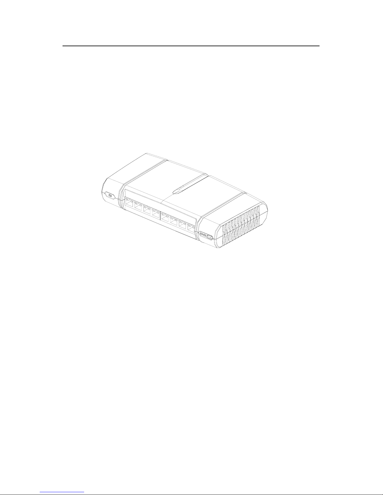
1.1.1 Appearance
Figure 1-1 S2008-EI Switch
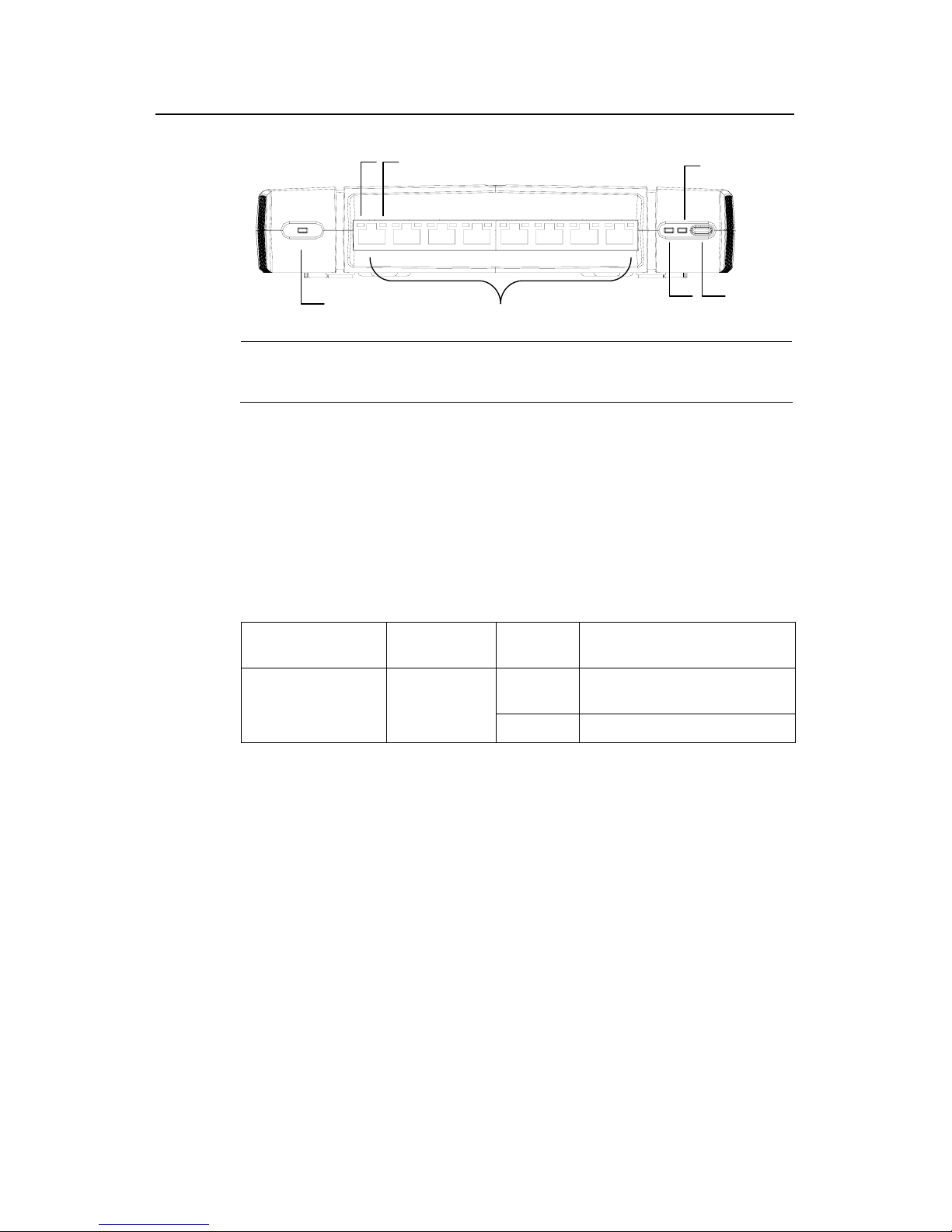
1.1.2 Front View
I. Front panel
On S2008-EI front panel distribute one power LED (POWER), eight fixed
10Base-T/100Base-TX auto-negotiation electrical ports, two status mode LEDs (A/L
and D/S), and one status mode control button (referred to as MODE button
throughout the rest of the manual). The eight fixed ports are RJ-45 connectors, each
with one yellow LED on the left and one green LED on the right. See the following
figure.
Installation Manual
Quidway S2000-EI Series Ethernet Switches Chapter 1 Product Overview
1-2
(1)
(5) (7)
(6)
(3)
(4)
(2)
(1)
(5) (7)
(6)
(3)
(4)
(2)
(1) POWER LED (2) Eight fixed electrical ports
(3) Port LED (left) (4) Port LED (right)
(5) A/L mode LED (6) D/S mode LED
(7) MODE button
Figure 1-2 S2008-EI front panel
II. LEDs on S2008-EI front panel
You can gather information about the status of the S2008-EI and the ports using the
LEDs on its front panel.
z POWER LED
Table 1-1 POWER LED on S2008-EI front panel
LED
Mark on the
front panel
Status Description
ON
The switch is being powered
normally.
POWER LED POWER
OFF The switch is not powered.
z Port LEDs
Before you can understand what the port LEDs mean, you should be aware of the
functions and relationships of the MODE button, A/L LED, and D/S LED:
1)
Only one of the A/L and D/S mode LEDs can light at one time. You can
toggle between them using the MODE LED. If A/L mode LED is ON, the
yellow/green LED for each port indicates the ACTIVE/LINK state of the port;
if D/S mode LED is ON, the mode of DUPLEX/SPEED.
2) A/L mode LED lights each time the switch is initialized.
3) D/S mode LED can light for a maximum of 45 seconds each time after you
toggle to it; and after that, A/L mode resumes. You can also toggle to the A/L
mode before that time by pressing the MODE button.
Installation Manual
Quidway S2000-EI Series Ethernet Switches Chapter 1 Product Overview
1-3
By toggling between the A/L and D/S mode LEDs using the MODE button, you can
gather information about ACTIVE/LINK state and DUPLEX/SPEED using the port
LEDs with reference to the following table:
Table 1-2 Port LEDs on S2008-EI front panel
Status
mode LED
Port LED status Description
Flashing (faster for heavier
traffic, and nearly steady
ON when the traffic is
tremendous)
Traffic is being received or transmitted
on the port.
Yellow
(ACTIVE)
OFF
There is no traffic being received or
transmitted on the port.
ON A LINK is UP (correctly connected).
A/L mode
LED ON
Green
(LINK)
OFF
There is no link present (due to LINK
DOWN or ERROR).
ON The port is in full duplex mode.
Yellow
(DUPLEX)
OFF The port is in half duplex mode.
Flashing (at frequencies of
12 Hz)
The port operates at 100 Mbps
Flashing (at frequencies of 3
Hz)
The port operates at 10 Mbps
D/S mode
LED ON
Green
(SPEED)
Steady ON There is no traffic on the port.
III. Fixed 10Base-T/100Base-TX Ethernet ports on S2008-EI front panel
Table 1-3 Attributes of the fixed 100Base-T Ethernet ports on S2008-EI front panel
Attribute Description
Connector RJ-45
Number of ports 8
Port attribute
10 Mbps half/full duplex
100 Mbps half/full duplex
Standard IEEE 802.3u
Max. transmission segment length over the
selected medium
100 m (328 ft) over the category-5 twisted pair cable
Installation Manual
Quidway S2000-EI Series Ethernet Switches Chapter 1 Product Overview
1-4
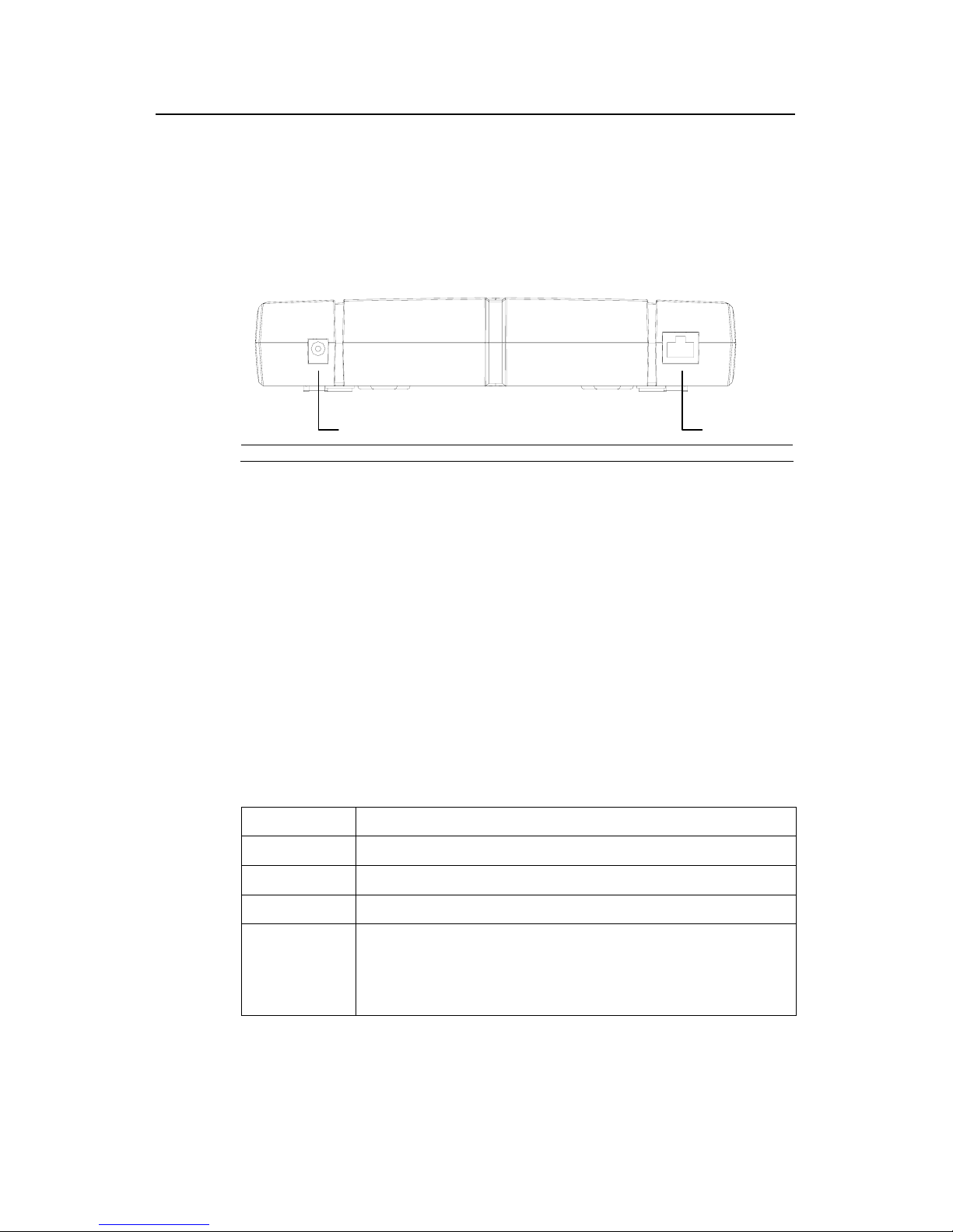
1.1.3 Rear View
I. Rear panel
On the S2008-EI rear panel distribute external power input and Console port (see the
following figure):
(1) (2)(1) (2)
(1) Power input (2) Console port
Figure 1-3 S2008-EI rear panel
The S2008-EI is powered using an external power supply that works with the
following specifications:
Rated voltage range: 100-240 V a.c., 50/60 Hz
Max. voltage range: 90-264 V a.c., 50/60 Hz
II. Console port
S2008-EI provides a Console port, which is an asynchronous serial port compliant
with EIA/TIA-232. Through this port, you can configure the switch at the local or
remotely.
Table 1-4 Console port attributes
Attribute Description
Connector RJ-45
Port standard Asynchronous EIA/TIA-232
Baud rate 9600 bps (default )
Service supported
z
Connection to the ASCII terminal
z
Connection to the serial port of a local terminal (which can be a PC) or a
remote terminal (through a pair of Modems) and running terminal
emulation program on the connected terminal
Installation Manual
Quidway S2000-EI Series Ethernet Switches Chapter 1 Product Overview
1-5
1.2 S2016-EI Ethernet Switch
The S2016-EI Switch falls into two models: S2016-EI-AC and S2016-EI-DC. They
differ only in the sense that the former is AC-powered and the latter is DC-powered.
Throughout the rest of the manual, both of them are referred to as S2016-EI if not
otherwise stated.
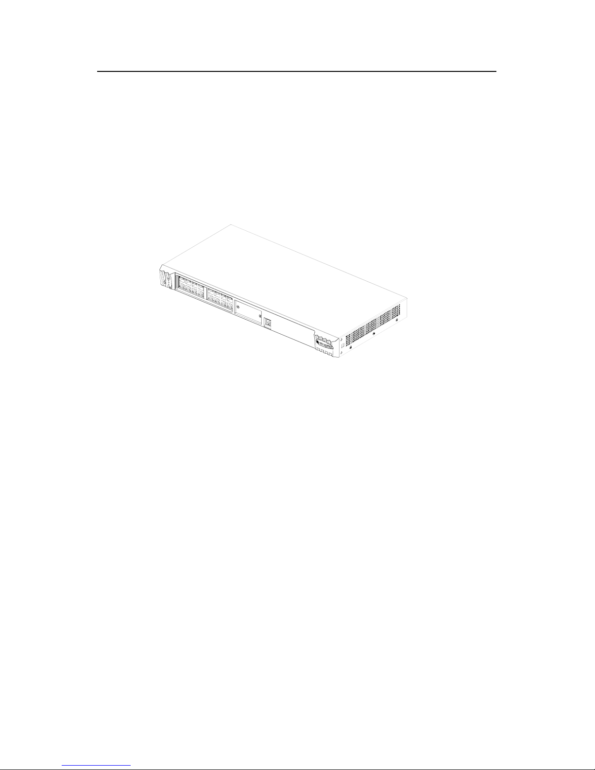
1.2.1 Appearance
Figure 1-4 S2016-EI Switch
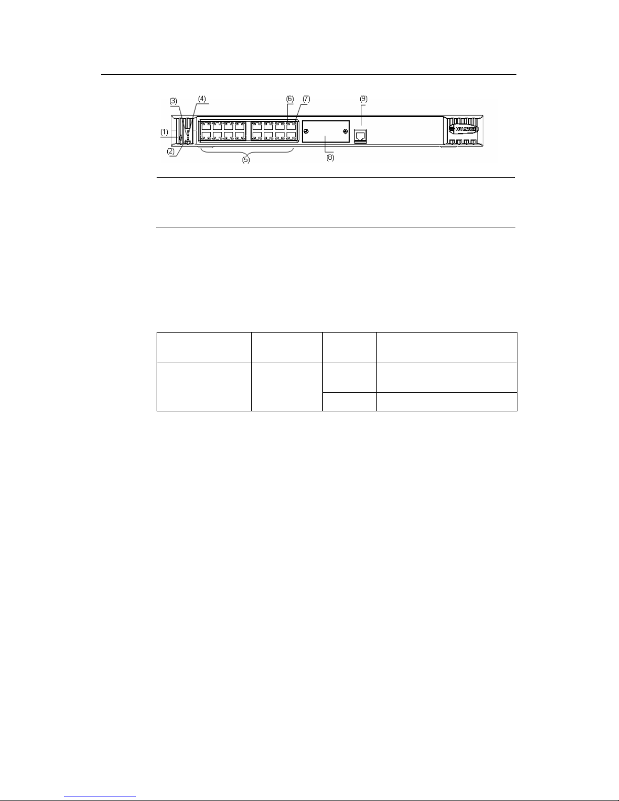
1.2.2 Front View
I. Front panel
On S2016-EI front panel distribute one status mode control button (referred to as
MODE button throughout the rest of the manual), one power LED (PWR), two status
mode LEDs (A/L, D/S), 16 fixed 10Base-T/100Base-TX auto-negotiation electrical
ports, one expansion slot, and one Console port. The 16 fixed ports are RJ-45
connectors, each with one yellow LED on the left and one green LED on the right.
See the following figure.
Installation Manual
Quidway S2000-EI Series Ethernet Switches Chapter 1 Product Overview
1-6
(1) MODE button (2) D/S mode LED
(3) A/L mode LED (4) PWR LED
(5) 16 fixed electrical ports (6) Port LED (left)
(7) Port LED (right) (8) Expansion slot
(9) Console port
Figure 1-5 Front panel of S2016-EI
II. LEDs on S2016-EI front panel
z PWR LED
Table 1-5 PWR LED on S2016-EI front panel
LED
Mark on the
front panel
Status Description
ON
The switch is being powered
normally.
PWR LED PWR
OFF The switch is not powered.
z Port LEDs
Before you can understand what the port LEDs mean, you should be aware of the
functions and relationships of the MODE button and A/L and D/S mode LEDs:
1)
Only one of the A/L and D/S mode LEDs can light at one time. You can
toggle between them using the MODE LED. If A/L mode LED is ON, the
yellow/green LED for each port indicates the ACTIVE/LINK state of the port;
if D/S mode LED is ON, the mode of DUPLEX/SPEED.
2) A/L mode LED lights each time the switch is initialized.
3) D/S mode LED can light for a maximum of 45 seconds each time after you
toggle to it; and after that, A/L mode resumes. You can also toggle to the A/L
mode before that time by pressing the MODE button.
z By toggling between the A/L and D/S mode LEDs using the MODE button, you
can gather information about ACTIVE/LINK state and DUPLEX/SPEED using the
port LEDs with reference to the following table:
Installation Manual
Quidway S2000-EI Series Ethernet Switches Chapter 1 Product Overview
1-7
Table 1-6 Port LEDs on S2016-EI front panel
Status
mode LED
Port LED status Description
Flashing (faster for heavier
traffic, and nearly steady
ON when the traffic is
tremendous)
Traffic is being received or transmitted
on the port.
Yellow
(ACTIVE)
OFF
There is no traffic being received or
transmitted on the port.
ON A LINK is UP (correctly connected).
A/L mode
LED ON
Green
(LINK)
OFF
There is no link present (due to LINK
DOWN or ERROR).
ON The port is in full duplex mode.
Yellow
(DUPLEX)
OFF The port is in half duplex mode.
Flashing (at frequencies of
12 Hz)
The port operates at 100 Mbps
Flashing (at frequencies of 3
Hz)
The port operates at 10 Mbps
D/L mode
LED OFF
Green
(SPEED)
Steady ON There is no traffic on the port.
III. Fixed 100Base-T Ethernet ports on S2016-EI front panel
Table 1-7 Attributes of the fixed 100Base-T Ethernet ports on S2016-EI front panel
Attribute Description
Connector RJ-45
Number of ports 16
Port attribute
10 Mbps half/full duplex
100 Mbps half/full duplex
Standard IEEE 802.3u
Max. transmission segment length over
the selected medium
100 m (328 ft) over the category-5 twisted pair cable
IV. Console port
S2016-EI provides a Console port compliant with EIA/TIA-232 asynchronous serial
specifications. Through this port, you can configure the switch at the local or remotely.
Installation Manual
Quidway S2000-EI Series Ethernet Switches Chapter 1 Product Overview
1-8
Table 1-8 Console port attributes
Attribute Description
Connector RJ-45
Port standard Asynchronous EIA/TIA-232
Baud rate 9600 (default)
Service supported
z
Connection to the ASCII terminal
z
Connection to the serial port of a local terminal (which can be a PC) or a
remote terminal (through a pair of Modems) and running terminal
emulation program on the connected terminal
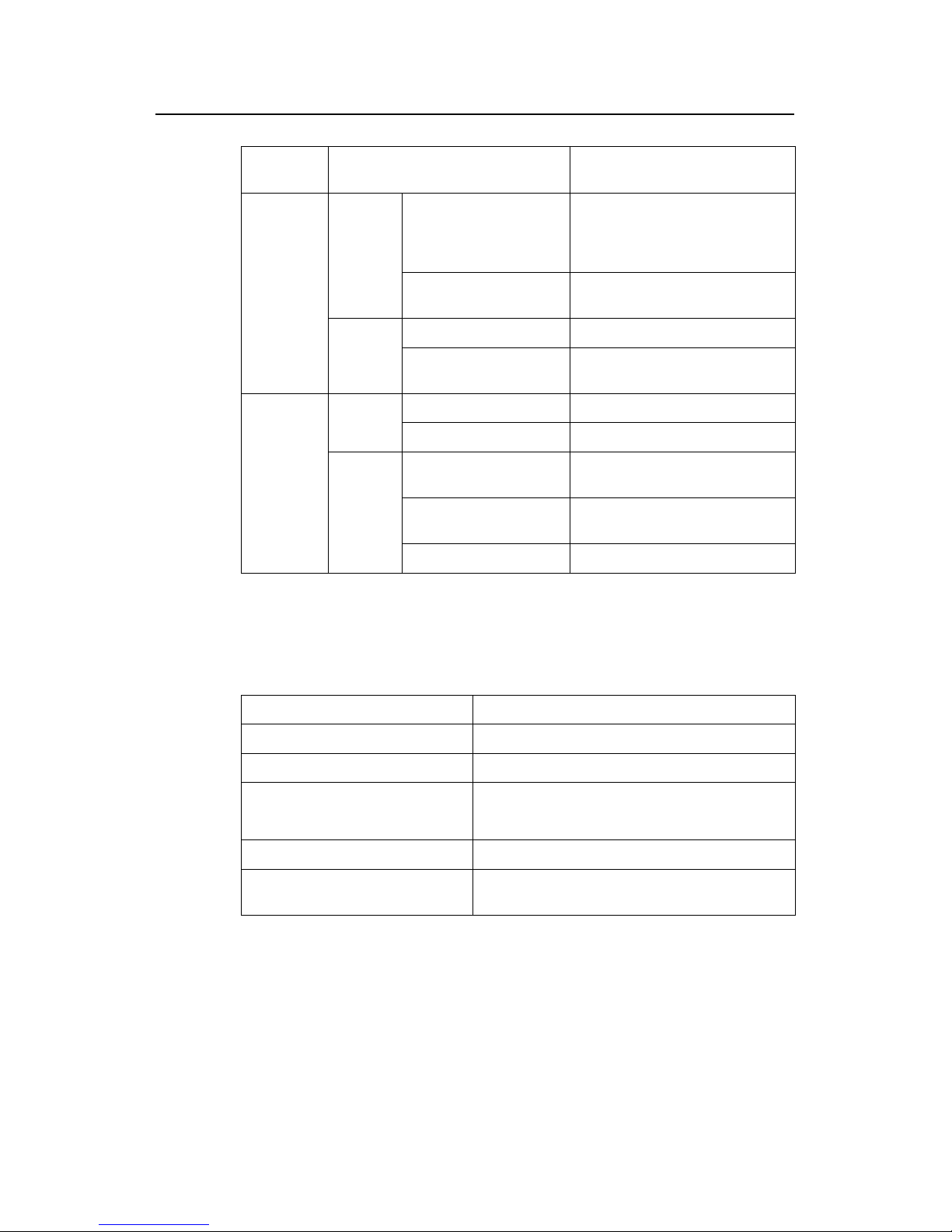
1.2.3 Rear View
I. S2016-EI-AC rear panel
(1)
(2)
(1)
(2)
(1) Grounding screw (2) AC power socket
Figure 1-6 S2016-EI-AC rear panel
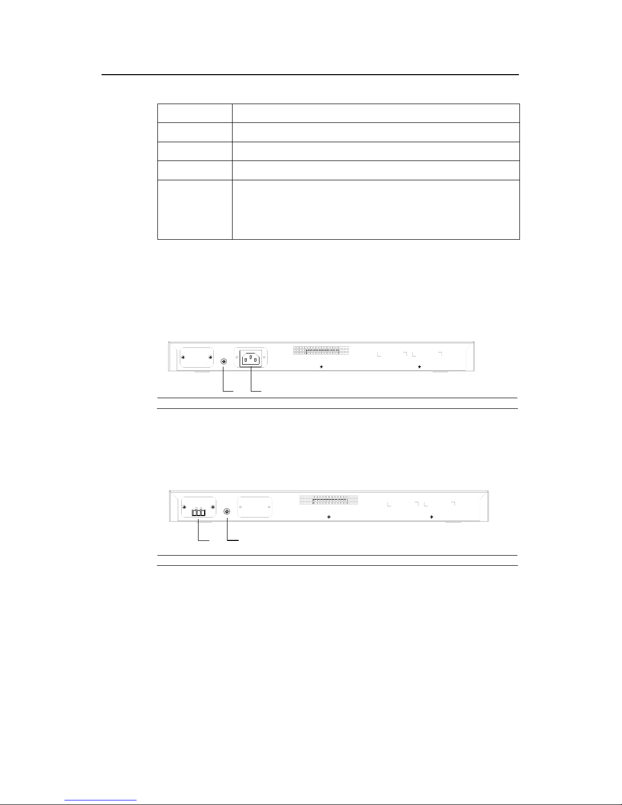
II. S2016-EI-DC rear panel
(1)
(2)
(1)
(2)
(1) power socket (2) Grounding screw
Figure 1-7 S2016-EI-DC rear panel
1.2.4 Optional Modules
z 1-port 100Base-FX single-mode module
z 1-port 100Base-FX multi-mode module
z 1-port 100Base-FX single-mode medium-haul module
z 1-port 100Base-T PoE (Power over Ethernet) interface module
Installation Manual
Quidway S2000-EI Series Ethernet Switches Chapter 1 Product Overview
1-9
1.3 S2403H-EI Ethernet Switch
The S2403H-EI Switch falls into two models: S2403H-EI-AC and S2403H-EI-DC.
They differ only in the sense that the former is AC-powered and the latter is
DC-powered. Throughout the rest of the manual, both of them are referred to as
S2403H-EI if not otherwise stated.
1.3.1 Appearance
Figure 1-8 S2403H-EI Switch
1.3.2 Front View
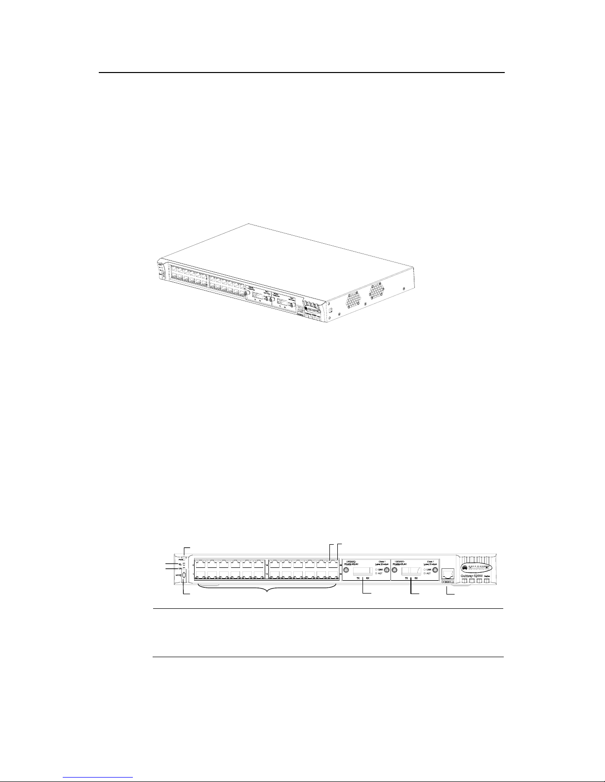
I. Front panel
On S2403H-EI front panel distribute one power LED (PWR), two status mode LEDs
(A/L and D/S), one status mode control button (referred to as MODE button
throughout the rest of the manual), 25 fixed 10Base-T/100Base-TX auto-negotiation
electrical ports, one expansion slot, and one Console port. The 25 fixed ports are
RJ-45 connectors, each with one yellow LED on the left and one green LED on the
right. See the following figure.
(1)
(2)
(3)
(4)
(5)
(8)
(9)
(10)
(6)
(7)
(1)
(2)
(3)
(4)
(5)
(8)
(9)
(10)
(6)
(7)
(1) PWR LED (2) A/L mode LED
(3) D/S mode LED (4) MODE button
(5) 24 fixed electrical ports (6) Port LED (left)
(7) Port LED (right) (8) No.25 fixed electrical port
(9) Expansion slot (10) Console port
Figure 1-9 S2403H-EI front panel
Installation Manual
Quidway S2000-EI Series Ethernet Switches Chapter 1 Product Overview
1-10
II. LEDs on S2403H-EI front panel
You can gather information about the status of the S2403H-EI and the ports using the
LEDs on its front panel.
z Power LED
Table 1-9 Power LED on S2403H-EI front panel
LED
Mark on the
front panel
Status Description
ON
The switch is being powered
normally.
PWR LED PWR
OFF The switch is not powered.
z Port LEDs
Before you can understand what the port LEDs mean, you should be aware of the
functions and relationships of the MODE button, A/L mode LED, and D/S mode L E D:
1)
Only one of the A/L and D/S mode LEDs can light at one time. You can
toggle between them using the MODE LED. If A/L mode LED is ON, the
yellow/green LED for each port indicates the ACTIVE/LINK state of the port;
if D/S mode LED is ON, the mode of DUPLEX/SPEED.
2) A/L mode LED lights each time the switch is initialized.
3) D/S mode LED can light for a maximum of 45 seconds each time after you
toggle to it; and after that, A/L mode resumes. You can also toggle to the A/L
mode before that time by pressing the MODE button.
Table 1-10 Port LEDs on S2403H-EI front panel
Status
mode LED
Port LED status Description
Flashing (faster for heavier
traffic, and nearly steady
ON when the traffic is
tremendous)
Traffic is being received or transmitted
on the port.
Yellow
(ACTIVE)
OFF
There is no traffic being received or
transmitted on the port.
ON A LINK is UP (correctly connected).
A/L mode
LED ON
Green
(LINK)
OFF
There is no link present (due to LINK
DOWN or ERROR).
Installation Manual
Quidway S2000-EI Series Ethernet Switches Chapter 1 Product Overview
1-11
Status
mode LED
Port LED status Description
ON The port is in full duplex mode.
Yellow
(DUPLEX)
OFF The port is in half duplex mode.
Flashing (at frequencies of
12 Hz)
The port operates at 100 Mbps
Flashing (at frequencies of 3
Hz)
The port operates at 10 Mbps
D/S mode
LED ON
Green
(SPEED)
Steady ON There is no traffic on the port.
III. Fixed 100Base-T Ethernet ports on S2403H-EI front panel
Table 1-11 Attributes of the fixed 100Base-T Ethernet ports on S2403H-EI front panel
Attribute Description
Connector RJ-45
Number of ports 25
Port attribute
10Mbps half/full duplex
100Mbps half/full duplex
Standard IEEE 802.3u
Max. transmission segment length over the
selected medium
100 m (328 ft) over the category-5 twisted pair cable
IV. Console port
S2403H-EI provides a Console port compliant with EIA/TIA-232 asynchronous serial
specifications. Through this port, you can configure the switch at the local or remotely.
Table 1-12 Console port attributes
Attribute Description
Connector RJ-45
Port standard Asynchronous EIA/TIA-232
Baud rate 9600 ( by default )
Service supported
z
Connection to the ASCII terminal
z
Connection to the serial port of a local terminal (which can be a PC) or a
remote terminal (through a pair of Modems) and running terminal
emulation program on the connected terminal
Installation Manual
Quidway S2000-EI Series Ethernet Switches Chapter 1 Product Overview
1-12
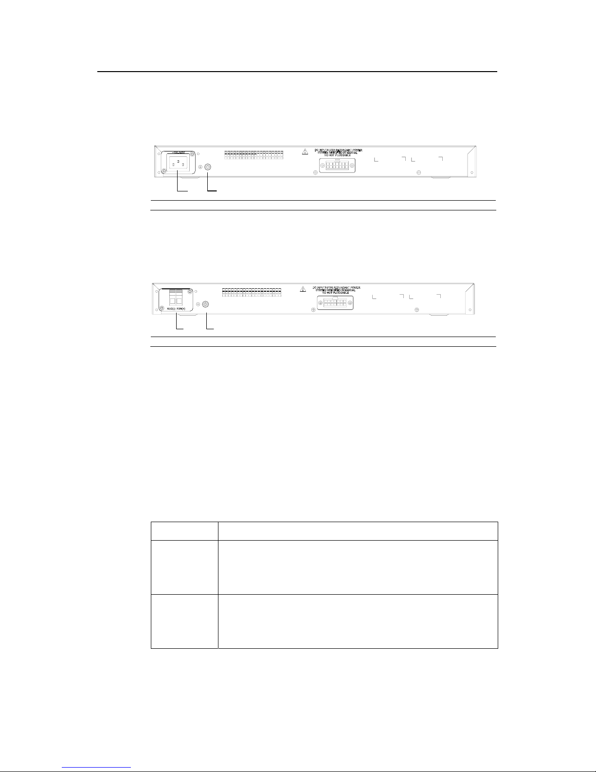
1.3.3 Rear View
I. S2403H-EI-AC rear panel
(1)
(2)
(1)
(2)
(1) AC power socket (2) Grounding screw
Figure 1-10 S2403H-EI-AC rear panel
II. S2403H-EI-DC rear panel
(1)
(2)
(1)
(2)
(1) DC power socket (2) Grounding screw
Figure 1-11 S2403H-EI-DC rear panel
1.3.4 Optional Modules
z 1-port 100Base-FX single-mode module
z 1-port 100Base-FX multi-mode module
z 1-port 100Base-FX single-mode medium-haul module
1.4 S2000-EI Series Specifications
Table 1-13 S2000-EI Series system features
Item S2000-EI Series Ethernet Switches
Dimensions (W
×
H × D)
S2008-EI: plastic chassis, 216mm x 40mm x 117mm (8.50 in x 1.57 in x 4.61 in)
S2016-EI: 436 mm x 42 mm x 200 mm (17.17 in x 1.65 in x 7.87 in)
S2403H-EI: 436 mm x 42 mm x 240 mm (17.17 in x 1.65 in x 9.45 in)
Weight
S2008-EI < 2 kg (4.41 Ib)
S2016-EI ≤ 3 kg (6.61 Ib)
S2403H-EI ≤ 3 kg (6.61 Ib)
 Loading...