

Huawei Quidway R3600 Installation Manual

HUAWEI
®
Quidway R2600/3600 Series Modular Routers
Installation Manual
V200R001

Quidway R2600/3600 Series Modular Routers
Installation Manual
Manual Version
T2-080430-20020202-C-1.0
Product Version
V200R001
BOM
31040430
Copyright © 2001 by Huawei Technologies Co., Ltd.
All Rights Reserved
No part of this document m ay be reproduc ed or transm itted in any form or by any
means without prior written consent of Huawei Technologies Co., Ltd.
Trademarks
®
, HUAWEI®, C&C08, EAST8000, HONET , Vie wP oin t, INt es s , ETS, DM C, SB S ,
TELLIN, InfoLink, Netkey, Quidway, SYNLOCK, Radium,
, M900/M1800,
TELESIGHT, Quidview, NETENGINE, Musa, OptiX, Airbridge, Tellwin, Inmedia,
VRP, DOPRA, iTELLIN are trademarks of Huawei Technologies Co., Ltd.
Notice
The information in this document is subject to change without notice. Although
every effort has been m ade to make this docum ent as accurate, complete, and
clear as possible, Hua wei Technologies assum es no responsibilit y for any errors
that may appear in this document.
Huawei Technologies Co., Ltd.
Address: Huawei Customer Service Building, Kefa Road, Science-based
Industrial Park, Shenzhen, P. R. China
Zip code: 518057
Tel: +86-755-6540036
Fax: +86-755-6540035
Website: http://www.huawei.com
E-mail: support@huawei.com

About This Manual
Contents
The manual consists of 8 chapters that brief the appear ance, features, installation,
configuration, maintenance, troubleshooting and function modules of Quidway
R2600/3600 Series Modular Routers.
Chapter 1 is a brief introduction of the Quidway R2600/3600 series modular
routers.
Chapter 2 describes the appearance and system features of Quidway
R2620/R2621, R2630/R2630E, R2631/R2631E, R3640/R3640E and
R3680/R3680E.
Chapter 3 introduces the installation preparations of the routers.
Chapter 4 introduces in detail the installation procedures of the routers.
Chapter 5 is about the startup and configuration of the routers.
Chapter 6 covers the software and hardware maintenance.
Chapter 7 is the troubleshooting procedur es during ins tall ation.
Chapter 8 depicts the function modules of the routers.
Target Readers
The manual is intended for the following readers:
Installation engineers & technicians
Operation & maintenance personnel
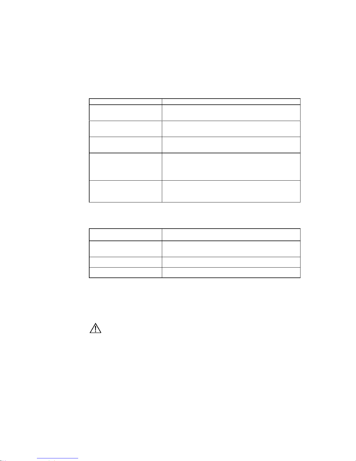
Conventions Used in the Document
Keyboard operation
Format Description
<Key >
Press the key with key name expressed with a pointed
bracket, e.g. <Enter>, <Tab>, <Backspace>, or <A >.
<Key 1 + Key 2>
Press the keys concurrently; e.g. <Ctrl+Alt+A> means the
three keys should be pressed concurrently.
<Key 1, Key 2> Press the keys in turn, e.g. <Alt, A> means the two keys
should be pressed in turn.
[Menu Option]
The item with a square bracket indicates the menu option,
e.g. [System] option on the main menu. The item with a
pointed bracket indicates the functional button option, e.g.
<OK> button on some interface.
[Menu 1/Menu 2/Menu 3] Multi-level menu options, e.g. [System/Option/Color setup]
on the main menu indicates [Color Setup] on the menu
option of [Option], which is on the menu option of [System].
Mouse operation
Action Description
Click Press the left button or right button quickly (left button by
default).
Double Click Press the left button twice continuously and qu ickly .
Drag Press and hold the left button a nd drag it to a cert ain positi on.
Symbol
Some distinct s ymbols are emplo yed in the manual to ind icate the s pecial notic e that
should be taken for the operation. The symbols are:
Caution, Notice, Warning, Danger: Notify the special attentio n that should be
given to the operation.
Note, Prompt, Tip, Thought: Give further necessary supp lement or explanation
for the operation description.

Installation Manual
Quidway R2600/3600 Series Modular Routers Table of Contents
i
Table of Contents
Chapter 1 Introduction................................................................................................................. 1-1
1.1 Quidway R2600/3600 Series Modular Routers ................................................................ 1-1
1.2 Models .............................................................................................................................. 1-1
1.3 Function Modules Supported............................................................................................ 1-1
1.4 Product Features .............................................................................................................. 1-2
1.5 Typical Application............................................................................................................1-3
Chapter 2 Appearance and System Features............................................................................ 2-1
2.1 Quidway R2620/R2621..................................................................................................... 2-1
2.1.1 Appearance............................................................................................................ 2-1
2.1.2 Indicators on Panel ................................................................................................ 2-2
2.1.3 System Description ................................................................................................ 2-2
2.2 Quidway R2630/R2630E .................................................................................................. 2-3
2.2.1 Appearance............................................................................................................ 2-3
2.2.2 Indicators on Panel ................................................................................................ 2-3
2.2.3 System Description ................................................................................................ 2-4
2.3 Quidway R2631/R2631E .................................................................................................. 2-5
2.3.1 Appearance............................................................................................................ 2-5
2.3.2 Indicators on Panels............................................................................................... 2-5
2.3.3 System Description ................................................................................................ 2-6
2.4 Quidway R3640/R3640E .................................................................................................. 2-6
2.4.1 Appearance............................................................................................................ 2-6
2.4.2 Indicators on Panel ................................................................................................ 2-7
2.4.3 System Description ................................................................................................ 2-7
2.5 Quidway R3680/R3680E .................................................................................................. 2-8
2.5.1 Appearance............................................................................................................ 2-8
2.5.2 Indicators on Panel ................................................................................................ 2-9
2.5.3 System Description ................................................................................................ 2-9
Chapter 3 Installation Preparations............................................................................................3-1
3.1 Safety Recommendations ................................................................................................. 3-1
3.2 Installation Conditions....................................................................................................... 3-1
3.2.1 Temperature and Humidity Requirements............................................................. 3-1
3.2.2 Cleanness Requirements....................................................................................... 3-2
3.2.3 ESD-Preventive Requirements.............................................................................. 3-3
3.2.4 Anti-interference Requirements ............................................................................. 3-3
3.2.5 Lightning Protection Requirements........................................................................ 3-3
3.2.6 Workbench Requirements...................................................................................... 3-4
3.3 Tools and Devices Required............................................................................................. 3-4

Installation Manual
Quidway R2600/3600 Series Modular Routers Table of Contents
ii
Chapter 4 Installation................................................................................................................... 4-1
4.1 Installation Flow ................................................................................................................ 4-1
4.2 Mechanical Installation ..................................................................................................... 4-1
4.2.1 Installing the Router in a Cabinet........................................................................... 4-2
4.2.2 Installing the Router on Workbench....................................................................... 4-2
4.3 Power Connection............................................................................................................. 4-3
4.3.1 Connecting Power Cable ....................................................................................... 4-3
4.3.2 Connecting Ground Cable...................................................................................... 4-5
4.4 Connecting Interface Cable on Main Control Panel ......................................................... 4-5
4.4.1 Connecting Console Port....................................................................................... 4-6
4.4.2 Connecting AUX Port ............................................................................................. 4-7
4.5 Connecting Interface Cable.............................................................................................. 4-9
4.6 Installation Check .............................................................................................................4-9
Chapter 5 Startup and Configuration ......................................................................................... 5-1
5.1 Starting the Router............................................................................................................ 5-1
5.1.1 Setting up Configuration Environment ................................................................... 5-1
5.1.2 Powering on Router ...............................................................................................5-4
5.1.3 Starting Router ....................................................................................................... 5-5
5.1.4 Configuring Router via Setup................................................................................. 5-6
5.2 Configuration Basic.......................................................................................................... 5-8
5.2.1 Basic Configuration Mode...................................................................................... 5-8
5.2.2 Help........................................................................................................................5-9
Chapter 6 Maintenance................................................................................................................ 6-1
6.1 Software Maintenance...................................................................................................... 6-1
6.1.1 BOOT Menu ........................................................................................................... 6-1
6.1.2 Upgrading Software via XModem .......................................................................... 6-2
6.1.3 Upgrading Main Program via TFTP ....................................................................... 6-4
6.1.4 Uploading and Downloading Files via FTP............................................................ 6-6
6.1.5 Password Lost........................................................................................................ 6-8
6.2 Hardware Maintenance..................................................................................................... 6-8
6.2.1 Opening the Chassis.............................................................................................. 6-9
6.2.2 Replacing the SIMM............................................................................................. 6-10
6.2.3 Replacing BOOTROM.......................................................................................... 6-14
6.2.4 Closing the Chassis ............................................................................................. 6-16
6.2.5 Replacing the Function Modules.......................................................................... 6-17
Chapter 7 Troubleshooting ......................................................................................................... 7-1
7.1 Power System................................................................................................................... 7-1
7.2 Configuration System .......................................................................................................7-1
Chapter 8 Function Modules....................................................................................................... 8-1
8.1 Introduction to Function Modules...................................................................................... 8-1
8.2 Arrangement of the Router Slots...................................................................................... 8-1

Installation Manual
Quidway R2600/3600 Series Modular Routers Table of Contents
iii
8.3 Function Modules Installation........................................................................................... 8-3
8.4 Function Modules Troubleshooting................................................................................... 8-5
8.5 1FE/2FE Module............................................................................................................... 8-5
8.5.1 Introduction.............................................................................................................8-5
8.5.2 Appearance............................................................................................................ 8-6
8.5.3 Interface Attributes................................................................................................. 8-7
8.5.4 Indicators on Panel ................................................................................................ 8-7
8.5.5 Interface Cable....................................................................................................... 8-8
8.5.6 Connecting Interface Cable.................................................................................. 8-10
8.6 2SA/4SA Module.............................................................................................................8-11
8.6.1 Introduction........................................................................................................... 8-11
8.6.2 Appearance.......................................................................................................... 8-13
8.6.3 Interface Attributes............................................................................................... 8-14
8.6.4 Indicators on Panel .............................................................................................. 8-15
8.6.5 Interface Cable..................................................................................................... 8-16
8.6.6 Connecting Interface Cable.................................................................................. 8-22
8.7 8AS/16AS Module........................................................................................................... 8-24
8.7.1 Introduction........................................................................................................... 8-24
8.7.2 Appearance.......................................................................................................... 8-25
8.7.3 Interface Attributes............................................................................................... 8-25
8.7.4 Indicators on Panel .............................................................................................. 8-26
8.7.5 Interface Cable..................................................................................................... 8-27
8.7.6 Connecting Interface Cable.................................................................................. 8-32
8.8 1E1/2E1/4E1 Module...................................................................................................... 8-33
8.8.1 Introduction........................................................................................................... 8-33
8.8.2 Appearance.......................................................................................................... 8-34
8.8.3 Interface Attributes............................................................................................... 8-35
8.8.4 Indicators on Panel .............................................................................................. 8-36
8.8.5 Interface Cable..................................................................................................... 8-37
8.8.6 Internal DIP Switches........................................................................................... 8-39
8.8.7 Connecting Interface Cable.................................................................................. 8-41
8.9 4BS Module .................................................................................................................... 8-43
8.9.1 Introduction........................................................................................................... 8-43
8.9.2 Appearance.......................................................................................................... 8-43
8.9.3 Interface Attributes............................................................................................... 8-44
8.9.4 Indicators on Panel .............................................................................................. 8-45
8.9.5 Interface Cable..................................................................................................... 8-46
8.9.6 Connecting Interface Cable.................................................................................. 8-46
8.10 2S1B Module ................................................................................................................ 8-46
8.10.1 Introduction......................................................................................................... 8-46
8.10.2 Appearance........................................................................................................ 8-47
8.10.3 Interface Attributes.............................................................................................8-47

Installation Manual
Quidway R2600/3600 Series Modular Routers Table of Contents
iv
8.10.4 Indicators on Panel ............................................................................................ 8-48
8.10.5 Interface Cable................................................................................................... 8-48
8.10.6 Connecting Interface Cable................................................................................ 8-49
8.11 2FXS/2FXO/2E&M Module...........................................................................................8-50
8.11.1 Introduction......................................................................................................... 8-51
8.11.2 Appearance........................................................................................................ 8-51
8.11.3 Interface Attributes.............................................................................................8-51
8.11.4 Indicators on Panel ............................................................................................ 8-52
8.11.5 Interface Cable................................................................................................... 8-53
8.11.6 Connecting Interface Cable................................................................................ 8-55
8.12 4FXS/4FXO/4E&M Module...........................................................................................8-56
8.12.1 Introduction......................................................................................................... 8-56
8.12.2 Appearance........................................................................................................ 8-56
8.12.3 Interface Attributes.............................................................................................8-57
8.12.4 Indicators on Panel ............................................................................................ 8-57
8.12.5 Interface Cable................................................................................................... 8-58
8.12.6 Connecting Interface Cable................................................................................ 8-58
8.13 8LSA Module ................................................................................................................ 8-59
8.13.1 Introduction......................................................................................................... 8-59
8.13.2 Appearance........................................................................................................ 8-60
8.13.3 Interface Attributes.............................................................................................8-60
8.13.4 Indicators on Panel ............................................................................................ 8-61
8.13.5 Interface Cable................................................................................................... 8-61
8.13.6 Connecting Interface Cable................................................................................ 8-66
8.14 E1VI Module .................................................................................................................8-67
8.14.1 Introduction......................................................................................................... 8-67
8.14.2 Appearance........................................................................................................ 8-67
8.14.3 Interface Attributes.............................................................................................8-67
8.14.4 Indicators on Panel ............................................................................................ 8-68
8.14.5 Interface Cable................................................................................................... 8-68
8.14.6 Connecting Interface Cable................................................................................ 8-70

Installation Manual
Quidway R2600/3600 Series Modular Routers
Chapter 1
Introduction
1-1
Chapter 1 Introduction
1.1 Quidway R2600/3600 Series Modular Routers
Quidway R2600/3600 series modular routers (referred to as R2600/3600 series
hereafter) are independe ntly developed b y Huawei for ent erprise net works. The y can
be used as core routers in medium- and small-sized Intranets, or as access servers at
some major branch offices.
With a modular structure, R2600/3600 series adopt the Versatile Routing Platform
(VRP), a proprietar y software platform of Huawei, and incorporate high-performance
processor, bus technology and fast routing policy. While providing a large array of
service interfaces, it can also be used together with Quidway
R1600 series, Quid way
R2500 series, and Quidway NetEngine08/16E series routers to provide overall
solutions for large- and medium-sized industry users such as telecom, private network
carrier, ISP, finance, tax, police, and railway , etc. At the same time, its function modules
comply with various network standards. So R2600/3600 series are in the best interests
to protect your existing investments while guaranteeing interoperability at various
levels with major products on the global market.
1.2 Models
R2600/3600 series include: R2620 , R2621, R2630, R 2631, R3640, R3680, R2 630E,
R2631E, R3640E and R3680E:
z R2620 and R2621 adopt Po wer PC 8240 CPU main b oard, but they differ from
other R2600/3600 series routers in that they have t wo fixed synchronous serial
interfaces besides the fixed Ethernet interfaces.
z R2630E, R2631E, R3640E and R 3680E differ from R2630, R2631, R3 640 and
R3680 in that the for mer adopt Power PC 82 40 CPU main board and the latter
adopt Pentium CPU main board. They have the same software features and
functional implem entations. The interf ace modules used by them are completel y
compatible, but the former are more po werful in their proces sing capability and
packet forwarding performance.
R2600/3600 series provide different number of module slots:
z Quidwa y R2620 provides on e 10/100Mbps Eth ernet interf aces, two synchro nous
serial interfaces, and two standard PCI slots.
z Quidway R2621 provides two 10/100Mbps Ethernet interface, two synchronous
serial interfaces and two standard PCI slots.
z
Quidway R2630/R2630E provid es one 10/100Mbps Fast Ethernet interf ace and
three standard PCI slots.
z Quidway R2631/R 2631E provid es two 10/100 Mbps Fast Ethernet inter faces and
three standard PCI slots.
z Quidway R3640/R3640E provides four standard PCI slots.
z
Quidway R3680/R3680E provides eight standard PCI slots.
1.3 Function Modules Supported
R2600/3600 series support the following function modules:

Installation Manual
Quidway R2600/3600 Series Modular Routers
Chapter 1
Introduction
1-2
z 1-port 10/100Base-TX Fast Ethernet interface module (1FE)
z
2-port 10/100Base-TX Fast Ethernet interface module (2FE)
z 2-port high-speed sync/async serial interface module (2SA)
z 4-port high-speed sync/async serial interface module (4SA)
z 2-port sync/async serial interface+1 port ISDN BRI S/T interface module (2S1B)
z
1-port channelized cE1/PRI interface module (1E1)
z 2-port channelized cE1/PRI interface module (2E1)
z 4-port channelized cE1/PRI interface module (4E1)
z
4-port ISDN BRI S/T interface module (4BS)
z 8-port async serial interface module (8AS)
z 16-port async serial interface m odule (16A S)
z 2-port voice interface module (FXS interface) (2FXS)
z
2-port voice interface module (FXO interface) (2FXO)
z 2-port voice interface module (E&M interface) (2E&M)
z
4-port voice interface module (FXS interface) (4FXS)
z 4-port voice interface module (FXO interface) (4FXO)
z 4-port voice interface module (E&M interface) (4E&M)
z 8-port low-speed sync/async serial interface module (8LSA)
z 1-port voice interface module (E1 interface) (E1VI)
When buying the R2600/3600 series, you can select proper function modules based on
your requirements, following the selection rules below:
z Multiple modules of the same type can be configured in the router.
z The module can be configured to any slot.
z The interface cable is directly related with specific module.
For details about the f unc tion modules and interf ac e c ab les, p le as e ref er to Ch apt er 8
Function Modules.
1.4 Product Features
I. Powerful backu p function
R2600/3600 series supp ort interf ace back up, li nk back up and rout e back up func tions,
of which the backup can be between DDN lin e an d d ia lup li ne, between DDN line an d
virtual link, or between dialup lines. It supports mutual backup between such networks
as DDN, X.25, PSTN, ISDN, and f ram e relay. It also s upports HSR P, and two ro uters
can be backup for each other.
II. Solution to remote office
R2600/3600 series provide solution to high-density remote office. It supports a
maximum of 112 analog dialup users (R3680/R3680E) or 28 I SDN BRI dialup users
(R3680/3680E).
III. E1/cE1 and cE1/PRI compatible
R2600/3600 series pro vide cE1 (Channelized E1) access, and the cE1 interface is
compatible with the E1 interface. At the same time, the ISDN PRI function can be
implemented on the cE1 interface.
IV. High density interfaces
R2600/3600 series support up to 28 2 Mbit/s sync serial interface (R3680/R3680E) ,
which can connect to such networks as DDN, frame relay, and X.25.

Installation Manual
Quidway R2600/3600 Series Modular Routers
Chapter 1
Introduction
1-3
V. Voice-related s upport features
R2600/3600 series support voic e features. It can provide t he following voice m odule
types for different users: 2FXS, 2FXO , 2E&M, 4FXS, 4FXO , 4E&M and E1VI , among
which:
z 2FXS and 4FXS modules are used to connect analog phones.
z
2FXO and 4FXO modules are used to connect loop trunks in the switching system.
z 2E&M and 4E&M modules are used for the connection of E&M trunks in the
switching system.
z E1VI module is used for the connection of E1 trunks in the switching system.
The voice modules of R2600/3600 s eries support m ultiple coding algor ithms suc h as
G.711, G.723 and G.729. It also supports H. 323 pr otocol s tack and G K i nterfac e, an d
demonstrates successf ul interopera bilit y with the equipm ent f rom such VoIP suppliers
as Cisco, AudioCodec, Motorola and VocalTec.
VI. Flexible memory configuration
Users can select the memory capacity flexibly according to system configuration,
number of function m odules, and performanc e requirement. Up to 256M B memor y is
supported.
VII. Others
R2600/3600 series support 100Mbps fast access to the local network and flexible
networking configuration.
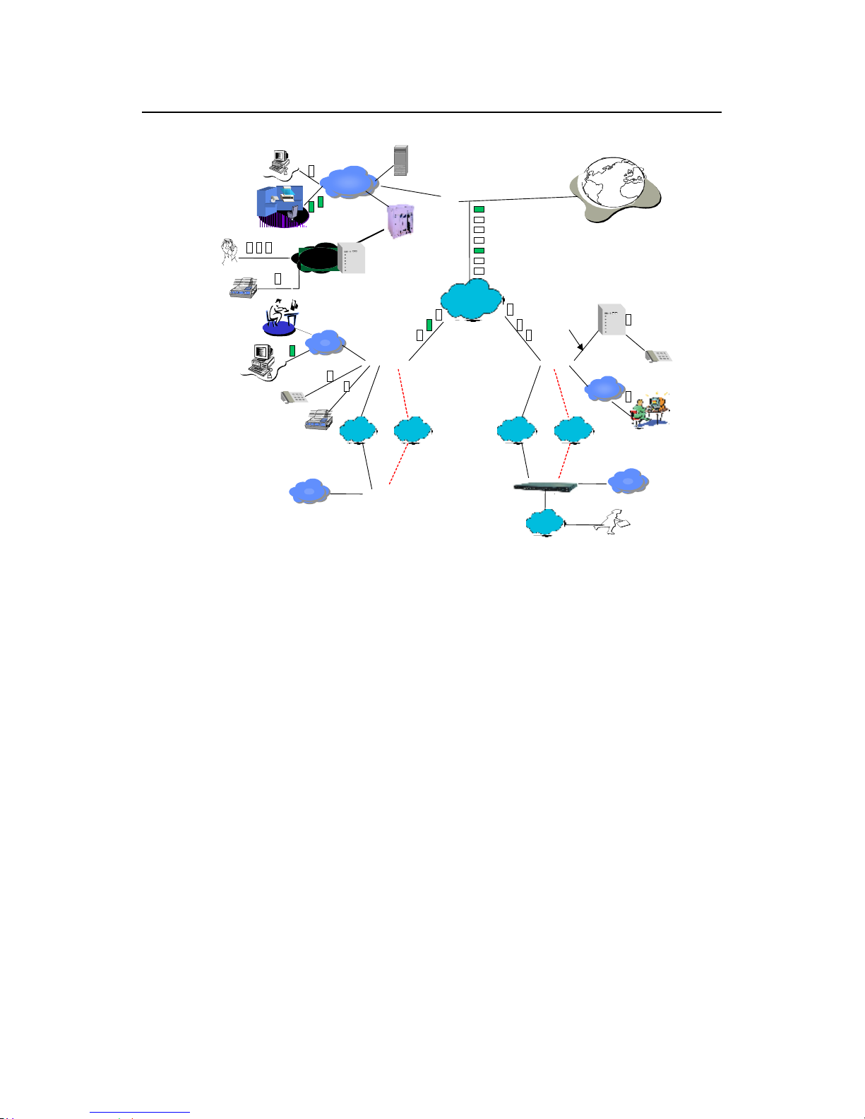
1.5 Typical Application
Installation Manual
Quidway R2600/3600 Series Modular Routers
Chapter 1
Introduction
1-4
Quidway
routers enterprise network solution
Internet
Phone
AT0/E&M
办公
办公办公
办公
LAN
DDN/FR
LAN
PBX
Branch Intranet
Branch Intranet
Quidway
3680
A8010Refiner
LAN
PBX
LAN
Server
GK
FAX
LAN
LAN
Central network
LAN
DDN/FR/
X25
LAN
PSTN/
ISDN
Quidway
1602/1603/1604
LAN
DDN/FR/
X25
LAN
PSTN/
ISDN
LAN
Level-3 Intranet
Level-3 Intranet
ISDN/
PSTN
representative office
Quidway2511/2509/4001
The red dotted line stands for backup line.
QuidwayR2600/3600
Quidway
R2600
/
3600
E1 trunk
Figure 1-1 Typical application of Quidway R2600/3600 series routers
Installation Manual
Quidway R2600/3600 Series Modular Routers
Chapter 2
Appearance and System Features
2-1
Chapter 2 Appearance and System Features
2.1 Quidway R2620/R2621
2.1.1 Appearance
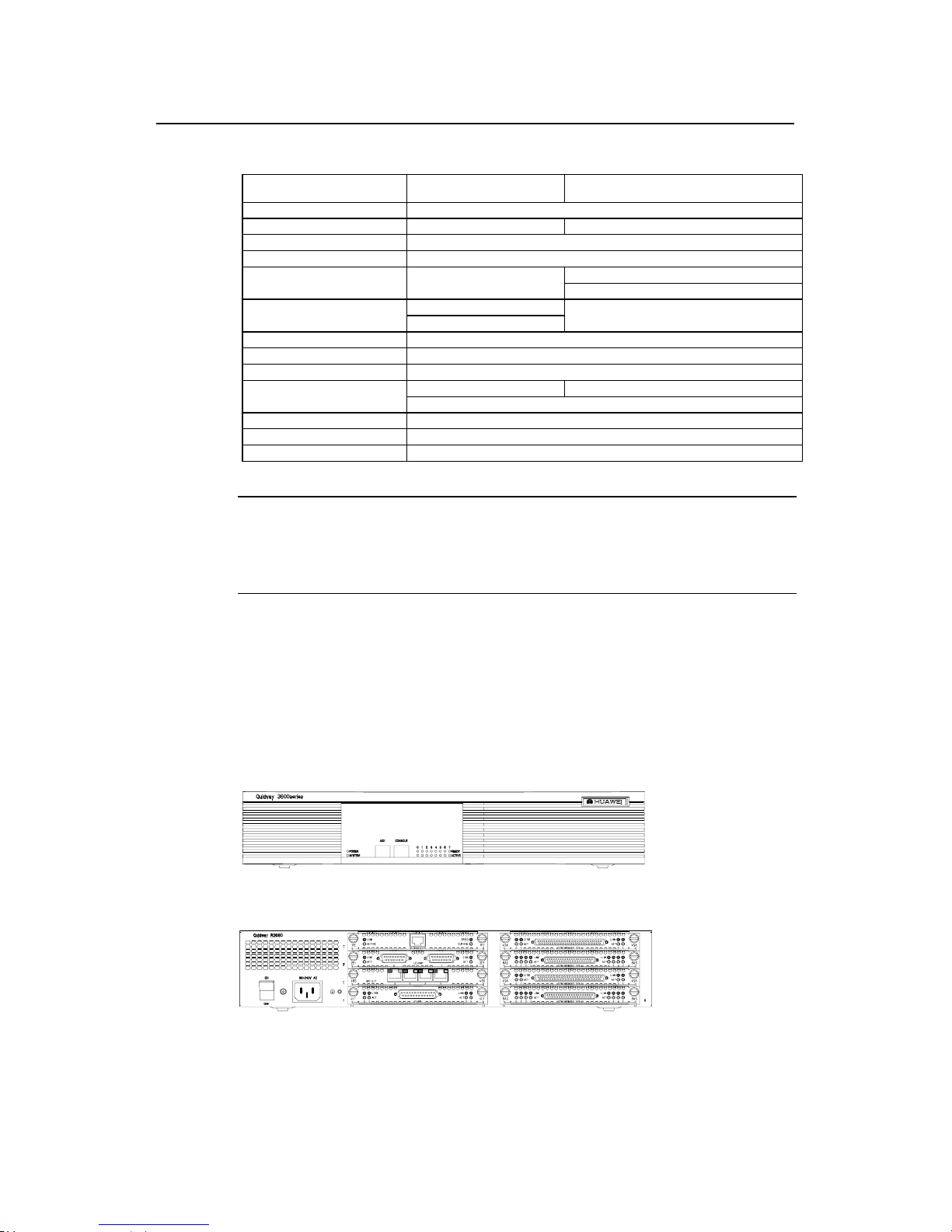
I. Appearance of R2620
The front panel and rear panel of R2620 are shown in the following figures.
SLOT0 SLOT1 WAN0 WAN1 LAN0
POWER
SYSTEM
READY
ACTIVE
LINK
ACTIVE
Figure 2-1 Front panel of R2620
AUX
CONSOLE
WAN1 WAN0
Figure 2-2 Rear panel of R2620
II. Appearance of R2621
The front panel and rear panel of R2621 are shown in the following figures.
SLOT0 SLOT1 WAN0 WAN1 LAN0 LAN1PO
POWER
SYSTEM
READY
ACTIVE
LINK
ACTIVE
Figure 2-3 Front panel of R2621
AUX
CONSOLE
WAN0WAN0WAN1
Figure 2-4 Rear panel of R2621

Installation Manual
Quidway R2600/3600 Series Modular Routers
Chapter 2
Appearance and System Features
2-2
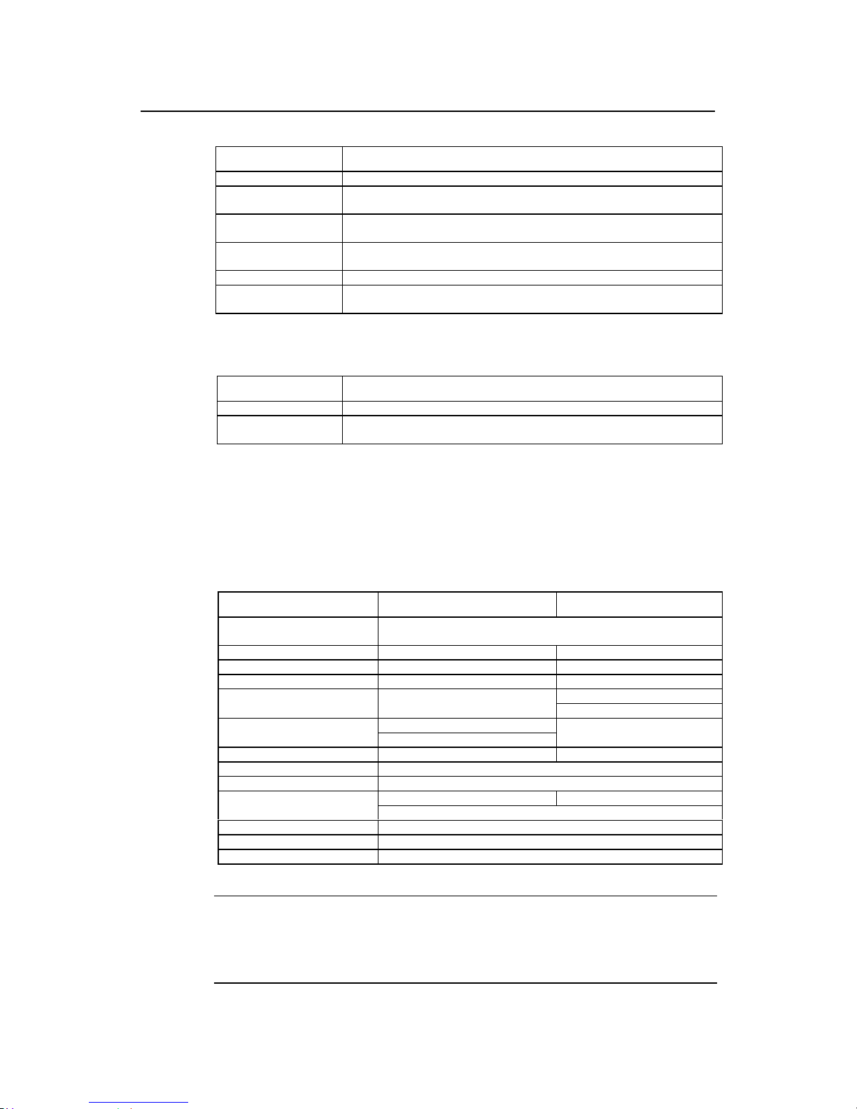
2.1.2 Indicators on Panel
The meanings of indicators on the front panel of R2620/R2621 are shown in the
following table.
Table 2-1 Meanings of indicators on the front panel of R2620/R2621
Indicator Meaning
POWER System power indicator: Off means power is off. On means power is on.
SYSTEM
Hardware status indicator. Blinking means system is normal. Always on/off
means system is abnormal.
READY
Module indicator. On means the modul e of th e current sl ot is wo rking normall y.
Off means the module is abnormal or no module is installed in the current slot.
ACTIVE
Blinking means data is being rec eived and transmitted by the module in the
current slot. Off means no data is being received or transmitted by the module in
the corresponding slot.
LINK Off means the LAN line is not connected. On means the LAN line is connected.
SLOT0-SLOT1 Indicating the corresponding slot number.
WAN0-WAN1 Indicating the corresponding WAN interface number.
LAN0, LAN1 (only for R2621) Indicating the corresponding Ethernet interface number.
The attributes of WAN0 and WAN1 interfaces of R2620/2621 are described in the
following table.
Table 2-2 Attributes of WAN0 and WAN1 interfaces of R2620/2621
Attribute Synchronous
Connector DB-50
V.24 V.35
Interface standards and
operating mode
DTE
DCE
DTE
DCE
Minimum baud rate (bit/s) 1200 1200
Maximum baud rate (bit/s) 64K 2.048M
Services supported
---Modem dial-up
---Backup
---Terminal access service
Protocols supported
---PPP
---MP
---LAPB
---X.25
---HDLC
---SDLC
---Frame Relay
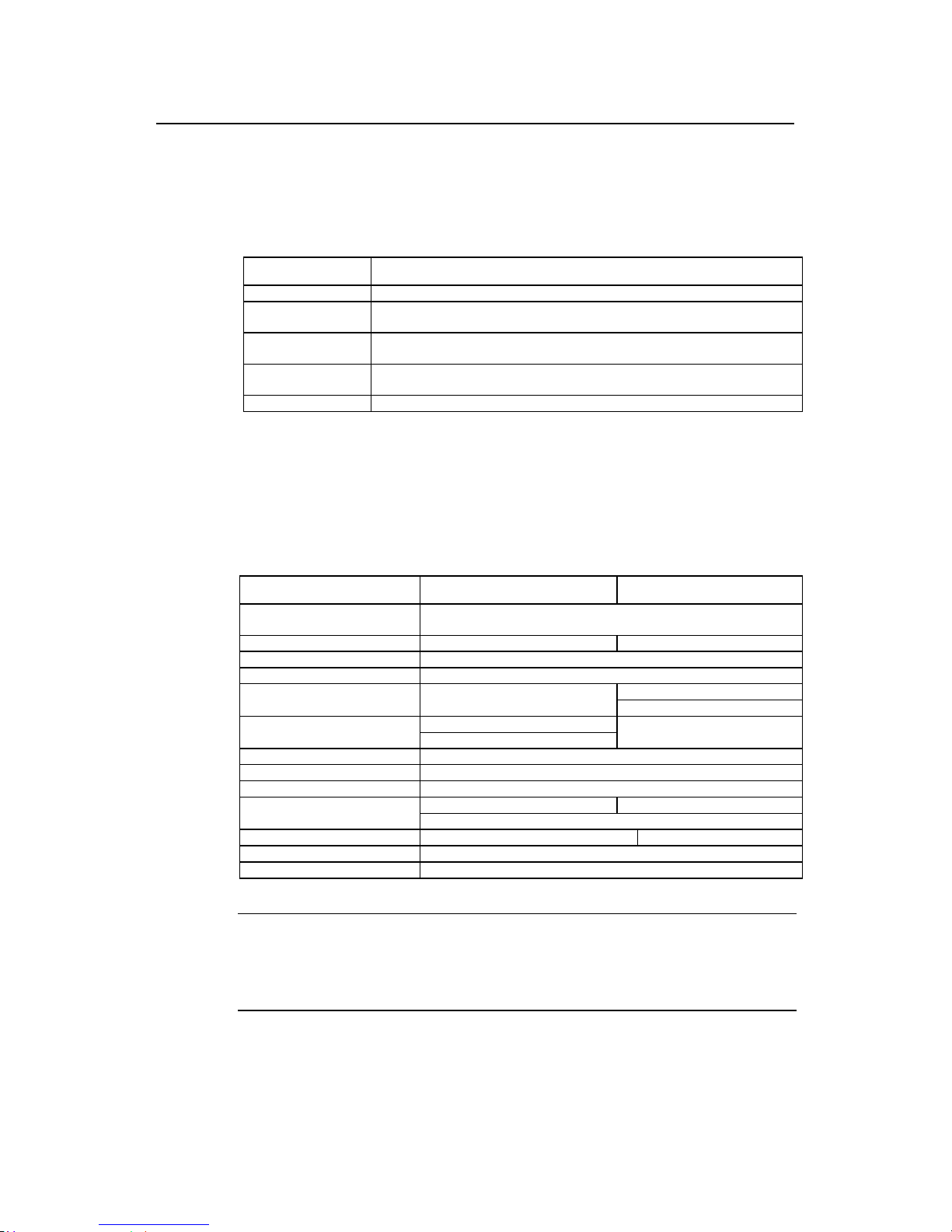
2.1.3 System Description
The table below shows th e basic configurations , dimensions, opera ting environment,
etc. of R2620 and R2621.
Installation Manual
Quidway R2600/3600 Series Modular Routers
Chapter 2
Appearance and System Features
2-3
Table 2-3 System description of R2620/R2621
Item Description of R2620 Description of R2621
Slot
A maximum of 2 function modules can be configured according to
requirement.
CPU Power PC 8240 200MHz
BOOT ROM 512KB 512KB
Default: 32MB
SDRAM
Max.: 128MB
FLASH 8MB
Dimensions Width x Height x Depth = 440mm x 86mm x 300mm
Weight 5kg
AC: 85V to 264V 50/60Hz
Input voltage
DC: -40V to -75V
Max. Power 70W
Operating temperature 0 to 40OC
Operating humidity 10 to 90% non-condensing
Note:
Dynamic memory (DRAM/SDRAM) works as main memory.
FLASH stores system programs.
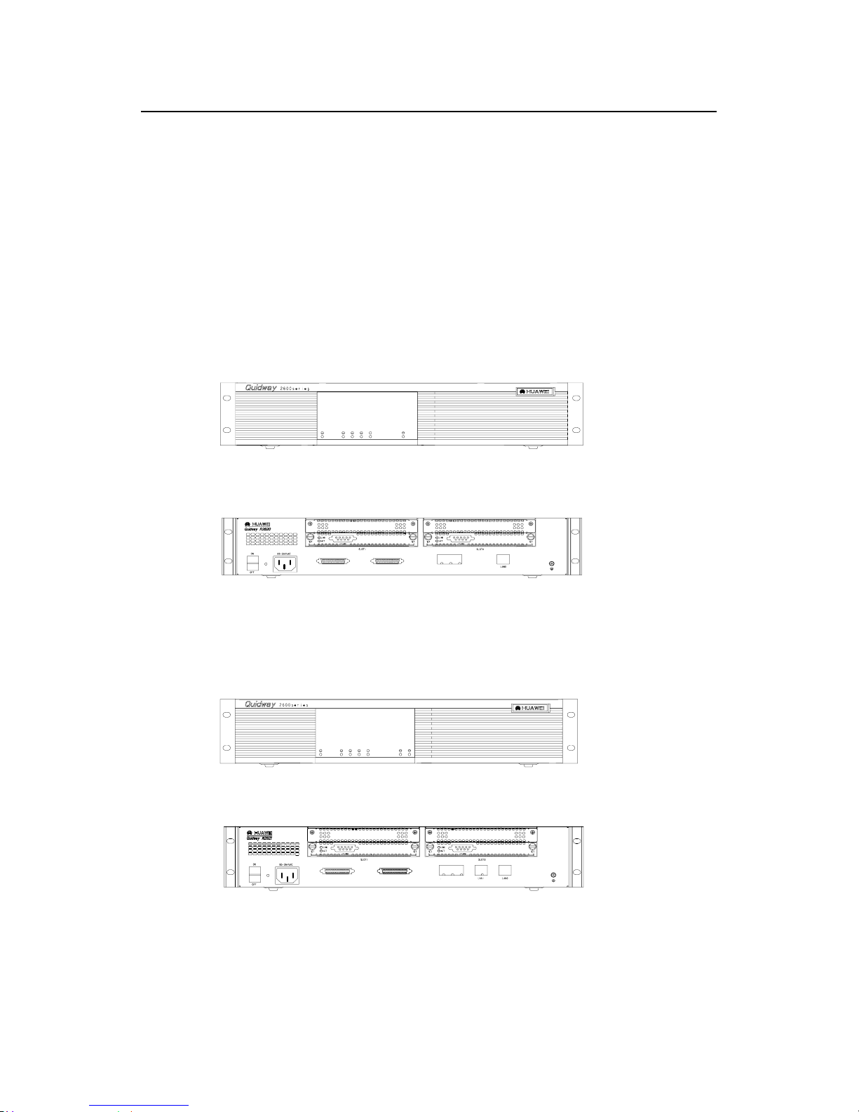
2.2 Quidway R2630/R2630E
2.2.1 Appearance
For R2630 and R2630E, their f ront panels and rear pa nels are ver y similar, see their
outlook as the following (take R2630 as an example).
Figure 2-5 Front panel of R2630
Figure 2-6 Rear panel of R2630
2.2.2 Indicators on Panel
The meanings of indicators on the front and rear panels of R2630/R2630E are shown in
the following tables.
Installation Manual
Quidway R2600/3600 Series Modular Routers
Chapter 2
Appearance and System Features
2-4
Table 2-4 Meanings of indicators on the front panel of R2630/R2630E
Indicator Meaning
POWER System power indicator: Off means power is off, On means power is on.
SYSTEM
Hardware status indicator. Blinking means the system runs normally. Always on/off
means the system is abnormal.
READY
Module status indicator: On means the module in corresponding slot runs normall y.
Off means the module runs abnormally or no module is installed.
ACTIVE
Blinking means data is being received or transmitted by the module in the
corresponding slot. Off means no data is being received or transmitted
0 - 2 Indicating the slot number.
LAN
Ethernet interface indicator: G reen means the interface is normal. Bli nking yellow
means data is being received and transmitted over the Ethernet.
Table 2-5 Meanings of indicators on the rear panel of R2630/R2630E
Indicator Meaning
LINK Off means the Ethernet link is not connected. On means the link is connected.
ACTIVE
Off means no data is being received and transmitted by the Ethernet interface.
Blinking means data is being received or transmitted.
2.2.3 System Description
The following table shows the basic configuration, dimensions, operating environment,
etc. of R2630 and R2630E.
Table 2-6 System description of R2630/R2630E
Item Description of R2630 Description of R2630E
Slot
A maximum of 3 interface modules can be configured according to
requirement.
CPU Pentium 133MHz Power PC 8240 200MHz
NVRAM 128KB 128KB
BOOTROM 512KB 512KB
Default: 64MB
SDRAM None
Max.: 256MB
Default: 32MB
DRAM
Max.: 128MB
None
FLASH 8MB
Dimensions Width x Height x Depth = 440mm x 43mm x 400mm
Weight 8kg
AC: 160 to 240V 50/ 60Hz AC: 85 to 264V 50/60Hz
Input voltage
DC: -40 to -75V
Max. power 80W
Operating temperature 0 to 40OC
Operating humidity 10 to 90% non-condensing
Note:
Dynamic memory (DRAM/SDRAM) works as main memory.
FLASH stores system programs.
NVRAM stores configuration files.
Installation Manual
Quidway R2600/3600 Series Modular Routers
Chapter 2
Appearance and System Features
2-5
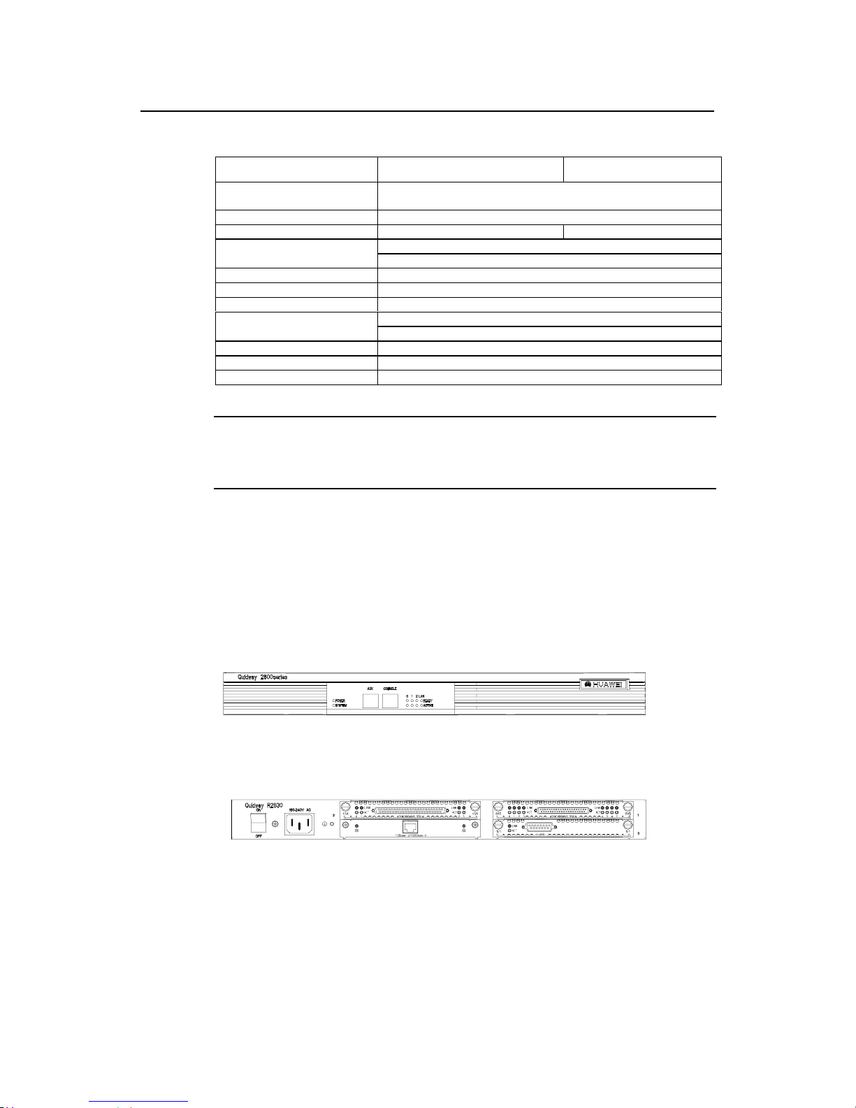
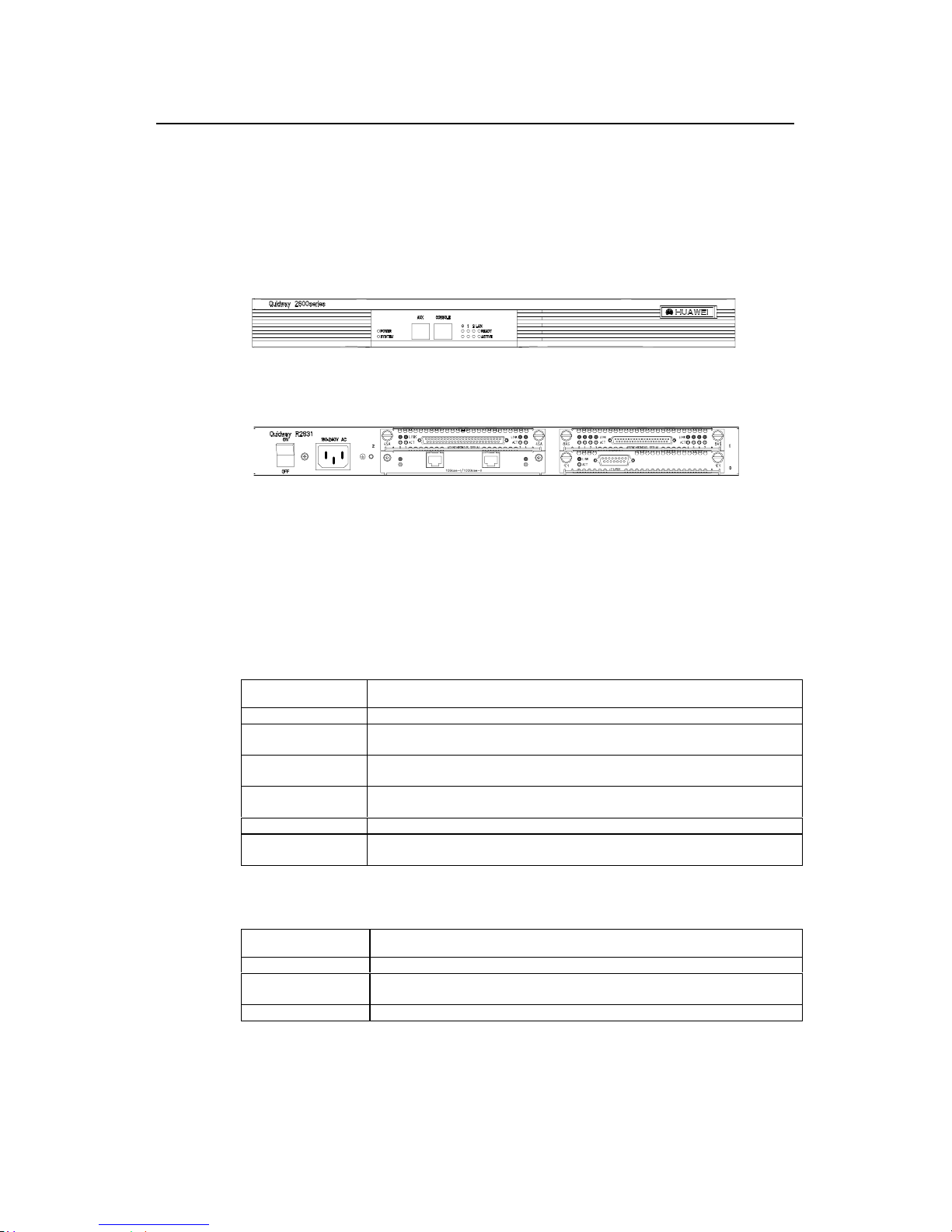
2.3 Quidway R2631/R2631E
2.3.1 Appearance
For R2631 and R2631E, their f ront panels and rear pa nels are ver y similar, see their
outlook as the following (take R2631 as an example).
Figure 2-7 Front panel of R2631
Figure 2-8 Rear panel of R2631
2.3.2 Indicators on Panels
The meanings of ind icators on the front and rear panels of R2631 and R2631E are
shown in the following tables.
Table 2-7 Meanings of indicators on the front panel of R2631/R2631E
Indicator Meaning
POWER System power indicator: Off means power is off. On means power is on.
SYSTEM
Hardware status indicator: Blinking means system is normal. Always on/off means the
system is abnormal.
READY
Module status indicator: On means the module r uns normally in the current slot. Off
means the module runs abnormally or no module is installed.
ACTIVE
Blinking means data is being received or transmitted by the module in the current slot. Off
means no data is being received or transmitted by the module in the current slot.
0 - 2 Position of the corresponding slots.
LAN
Ethernet interface indicator. Green means the interface is normal. Blinking yellow means
that data is being received or transmitted over the Ethernet.
Table 2-8 Meanings of indicators on the rear panel of R2631/R2631E
Indicator Meaning
LINK Off means the Ethernet link is not connected. On means the link is connected.
ACTIVE
Off means no data is being received or transmitted by the Ethernet interface. Blinking
means data is being received or transmitted.
0 - 1 Corresponding port number.
Installation Manual
Quidway R2600/3600 Series Modular Routers
Chapter 2
Appearance and System Features
2-6
2.3.3 System Description
The following table shows the basic configuration, dimensions, operating environment,
etc. of R2631 and R2631E.
Table 2-9 System description of R2631/R2631E
Item Description of R2631 Description of R2631E
Slot
A maximum of 3 interface modules can be configured according to
requirement.
CPU Pentium133MHz Power PC 8240 200MHz
NVRAM 128KB
BOOT ROM 512KB
Default: 64MB
SDRAM None
Max.: 256MB
Default: 32MB
DRAM
Max.: 128MB
None
FLASH 8MB
Dimensions Width x Height x Depth = 440mm x 43mm x 400mm
Weight 8kg
AC: 160 to 240V 50/ 60Hz AC: 85 to 264V 50/ 60Hz
Input voltage
DC: -40V to -75V
Max. power (with 3 modules) 80W
Operating temperature 0 to 40OC
Operating humidity 10 to 90% non-condensing
Note:
Dynamic memory (DRAM/SDRAM) works as main memory.
FLASH stores system programs.
NVRAM stores configuration files.
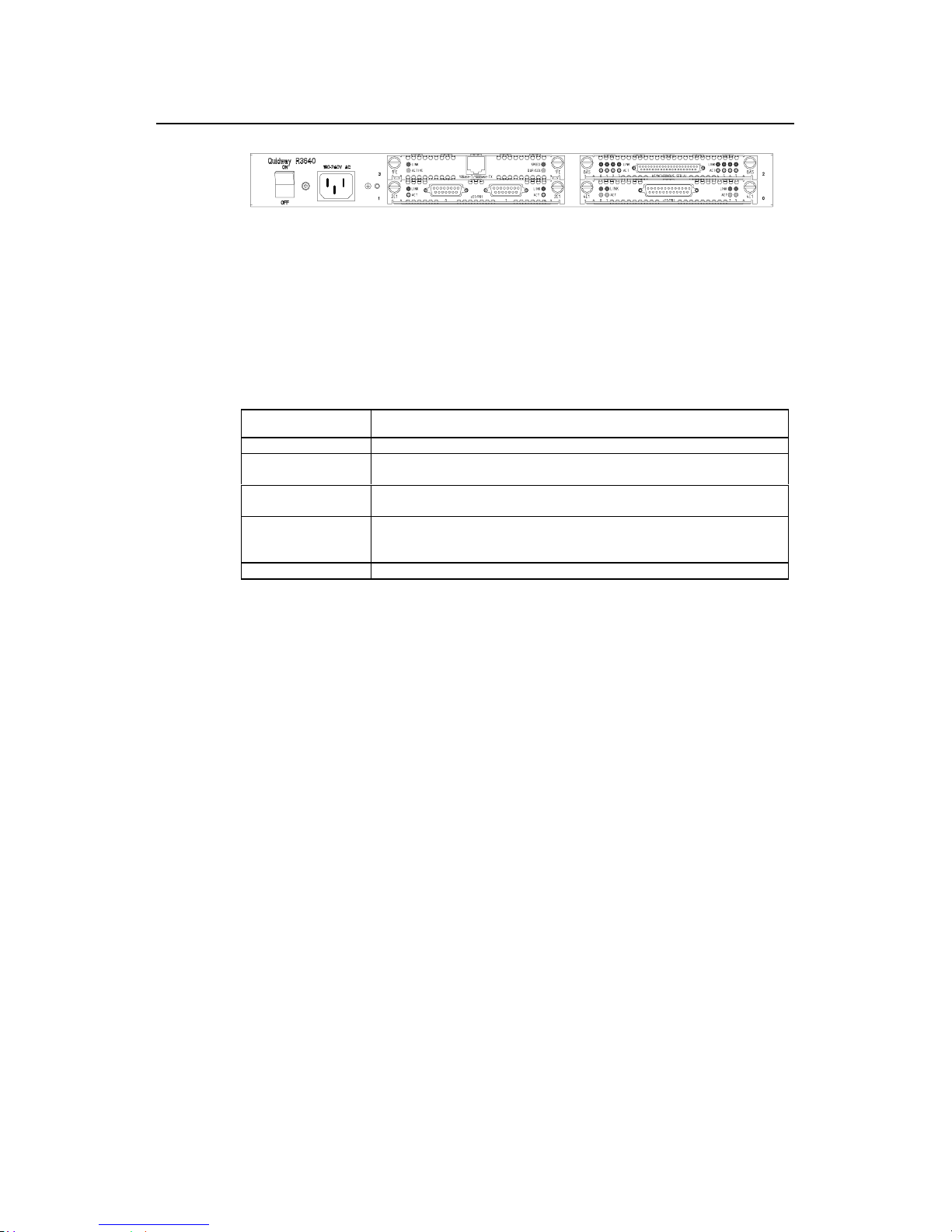
2.4 Quidway R3640/R3640E
2.4.1 Appearance
For R3640 and R3640E, their f ront panels and rear pa nels are ver y similar, see their
outlook as the following (take R3640 as an example)
Figure 2-9 Front panel of R3640
Installation Manual
Quidway R2600/3600 Series Modular Routers
Chapter 2
Appearance and System Features
2-7
Figure 2-10 Rear panel of R3640
2.4.2 Indicators on Panel
The meanings of indicators on the front panel of R3640/R3640E are shown in the
following table.
Table 2-10 Meanings of indicators on the front panel of R3640/R3640E
Indicator Meaning
POWER System power indicator: Off means power is off. On means power is on.
SYSTEM
Hardware status indicator: Blinking means system is normal. Always on/off means
system is abnormal.
READY
Module indicator. On means the module of the current slot is working normally. Off
means the module is abnormal or no module is installed in the current slot.
ACTIVE
Blinking means data is being received and transmitted by the module in the current
slot. Off means no data is being received or transmitted by the module in the current
slot.
0 - 3 Position of corresponding slots.
2.4.3 System Description
The following table shows the basic configurations, dimensions, operating environment,
etc. of R3640 and R3640E.
Installation Manual
Quidway R2600/3600 Series Modular Routers
Chapter 2
Appearance and System Features
2-8
Table 2-11 System Description of R3640/R3640E
Item Description of R3640 Description of R3640E
Slot A maximum of 4 function modules can be configured according to requirement.
Processor Pentium 133MHz Power PC 8240 250MHz
NVRAM 128KB
BOOT ROM 512KB
Default: 128MB
SDRAM None
Max.: 256MB
Default: 32MB
DRAM
Max.: 128MB
None
FLASH 8MB
Dimensions Width x Height x Depth = 440mm x 43mm x 400mm
Weight 8kg
AC: 160 to 240V 50/60Hz AC: 85 to 264V 50/60Hz
Input voltage
DC: -40V to -75V
Max. power (with 4 modules) 80W
Operating temperature 0 to 40OC
Operating humidity 10 to 90% non-condensing
Note:
Dynamic memory (DRAM/SDRAM) works as main memory.
FLASH stores system programs.
NVRAM stores configuration files.
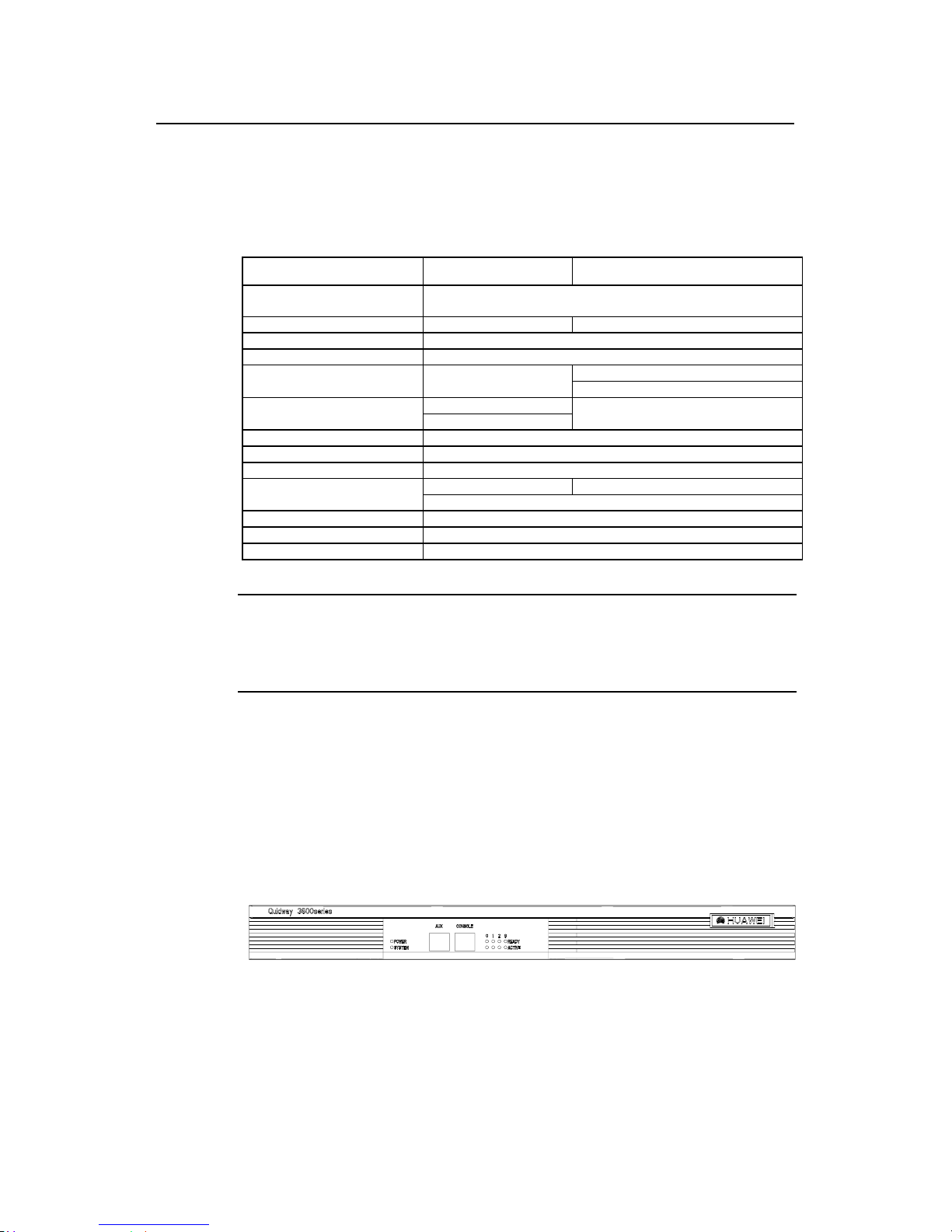
2.5 Quidway R3680/R3680E
2.5.1 Appearance
For R3680 and R3680E, their f ront panels and rear pa nels are ver y similar, see their
outlook as the following (take R3680 as an example)
Figure 2-11 Front panel of R3680
Figure 2-12 Rear panel of R3680/R3680E
Installation Manual
Quidway R2600/3600 Series Modular Routers
Chapter 2
Appearance and System Features
2-9
2.5.2 Indicators on Panel
The meanings of indicators on the front panel of R3680/R3680E are shown in the
following table.
Table 2-12 Meanings of indicators on the front panel of R3680/R3680E
Indicator Meaning
POWER System power indicator: Off means power is off. On means power is on.
SYSTEM
Hardware status indicator: Blinking means system is normal. Always on/off means
system is abnormal.
READY
Module indicator. On means the modul e of the current slot is working normally. Off
means the module is abnormal or means no module is installed in the current slot.
ACTIVE
Blinking means data is being received and transmitted by the module on the current slot.
Off means no data is being received or transmitted by the module in the current slot.
0 - 7 Position of corresponding slots.
2.5.3 System Description
The following table shows the basic configurations, dimensions, operating environment,
etc. of R3680 and R3680E.
Table 2-13 System description of R3680/R3680E
Item Description of R3680 Description of R3680E
Slot
A maximum of 8 function modules can be configured according to
requirement.
CPU Pentium MMX-166MHz Power PC 8240 250MHz
NVRAM 128KB
BOOT ROM 512KB
Default: 128MB
SDRAM None
Max.: 256MB
Default: 64MB
DRAM
Max.: 128MB
None
FLASH 8MB
Dimensions Width x Height x Depth = 440mm x 86mm x 400mm
Weight 14kg
AC: 160 to 240V 50/ 60Hz AC: 85 to 264V 50/60Hz
Input voltage
DC: -40V to -75V
Max. power (with 8 modules) 130W 120W
Operating temperature 0 to 40OC
Operating humidity 10 to 90% non-condensing
Note:
Dynamic memory (DRAM/SDRAM) works as main memory.
FLASH stores system programs.
NVRAM stores configuration files.

Installation Manual
Quidway R2600/3600 Series Modular Routers
Chapter 3
Installation Preparations
3-1
Chapter 3 Installation Preparations
3.1 Safety Recommendations
Routers play the key role in data communications network. Please pay attention to the
following:
Warning: It indicates that this operation may seriously damage the router or
endanger the operator. Please follow the operation procedures for sake of safety.
Caution: It indicates that during the installation and usage of the router, the
operation needs attention . T hough this operatio n wil l not do an y dam age to t he router
or endanger the operator, it may affect the normal operation of the router.
Please follow the f ollowing s afety recom mendatio ns during t he insta llation a nd use of
the router:
z Keep the router away from water or any wet place.
z
Keep the router away from any heat source.
z Make sure that the router is normally grounded.
z Wear ESD-preventive wrist strap during installation.
z Do not hot unplug the modules of the router.
z Do not hot unplug any cable.
z Always use UPS.
3.2 Installation Conditions
R2600/3600 series must be used indoors. T o ensure the normal operation and prolong
their service life, the following requirements for installation site must be met.
3.2.1 Temperature and Humidity Requirements
Certain requirements on temperature and humidity in the equipment room shall be met.
If the relative humidity is too high, the insulation materials in it will deteriorate easily or
even lead to electric leakage. Sometim es this will res ult in change to the mec hanical
performance of the materials and rusting of the metal components. If the relative
humidity is too lo w, the fastening screw will become loosen due to shrink age of the
isolation spacer. In an environment with dry climate, the static electricity may be
produced, putting the CMOS of the r outer to risk . High tem perature is of the great est
risk: for it will significantly degrade the router’s reliability, speed up the aging process of
the insulating materials, and shorten the service life of the router. The requirements on
the temperature and humidity for R2600/3600 series are shown in Table 3-1:

Installation Manual
Quidway R2600/3600 Series Modular Routers
Chapter 3
Installation Preparations
3-2
Table 3-1 Humidity requirement in the equipment room
Temperature Relative humidity
Normal operating condition
Safety operating
condition
Normal operating condition
Safety operating
condition
15OC to 30OC0
O
Cto 45OC 40% to 65% 10% to 90%
Note:
1) The values of environmental temperature and humidity in the equipment room are measured at 1.5m
high and 0.4m away from the front of the router rack when there is no protective board installed in front and
at the back of the rack.
2) Safety operating condition refers to the continuous operation for less than 48 hours or the accumulative
annual operation time less than 15 days.
3) The extreme environment refers to the likely environmental temperature and humidity when the air
conditioning system in the equipment room fails (the normal operating condition should be recovered
within five hours for each failure).
3.2.2 Cleanness Requirements
Dust undermines the nor mal operation of R2600/3600 series . Dust dropping on the
equipment can cause electrostatic adsorption, which degrades the contact
performance of the metal connection parts or connectors. This happens more
frequently when the indoor relative humidity is low, which will not only shorten the
router’s service life, but also cause communication failure.
The recommended specification on dust content and particle diameter in the equipment
room is shown in Table 3-2:
Table 3-2 Specification on dust content in equipment room
Maxim diameter ( m)
Max. intensity (particles per cubic meter)
0.5 1.4 x 10
7
17 x 10
5
3 2.4 x 10
5
5 1.3 x 10
5
The routers also have rigorous demand on the content of salts, acids and sulfides in the
air. These harmful gases will speed up the metal rust ing and the aging pr ocesses of
certain parts. The equipm ent room should be protec ted from the invasio n of harmful
gases such as SO
2, H2
S, NO2, NH3 and Cl2, the value limits of which are shown in T able
3-3:

Installation Manual
Quidway R2600/3600 Series Modular Routers
Chapter 3
Installation Preparations
3-3
Table 3-3 Value limits for harmful gas contents in equipment room
Gas Average (mg/m3) Max. (mg/m3)
SO
2
0.2 1.5
H2S 0 0.03
NO
2
0.04 0.15
NH
3
0.05 0.15
Cl
2
0.01 0.3
3.2.3 ESD-Preventive Requirements
Although many antistatic considerations have been given to R2600/3600 series,
damage to the router’s circuit or e ve n th e whole eq uipment may still happen when the
static electricity exceeds the tolerance threshold.
In the communication network to which the routers are connected, static induction
mainly comes from:
z
External electric fields such as outdoor high voltage power line or thunder.
z Internal environment like flooring materials or the whole equipment structure.
Thus, the following should be considered to safeguard the equipment against the static
damage:
z Make sure that the equipment and the floor are well grounded.
z Make sure that dust-proof measures are taken.
z
Maintain an appropriate humidity and temperature.
z Wear an ESD-preventive wrist strap and uniform when contacting the circuit
board.
z
Place the uninstalled circuit board on the antistatic workbench, with its face
upward, or put it into the electromagnetic shield bag.
z When observing or removing the unins talle d circ uit bo ard, please to uch th e edge
of the circuit board, and avoid contacting the devices on it.
3.2.4 Anti-interference Requirements
The interference sources, no matter where they come from, affect the routers with
capacitance coupling, inductance coupling, radiation of electromagnetic wave,
common impedance (incl uding the grounding syst em) or conducting line ( power line,
signal line and transmission line etc.).
So the following should be considered:
z Take effective measures to prevent the power system from being interfered with
by the power grid system.
z
Separate the working ground of the router from the grounding device of the power
supply equipment or anti-lightning grounding device as far as possible.
z
Keep the router far away from the radio launcher, radar launcher, and high-
frequency devices working in high currents.
z Use electromagnetic shielding when necessary.
3.2.5 Lightning Protection Requirements
Although many measures have been taken to protect R2600/3600 series from lightning,
if the lightning intensity exceeds a certain range, damage to the router may still happen.
To protect the router from lightning better, the following should be considered:

Installation Manual
Quidway R2600/3600 Series Modular Routers
Chapter 3
Installation Preparations
3-4
z
Ensure the shell of the chassis is well grounded through the ground wire.
z Ensure the neutral point of the socket of AC power supply is well grounded.
z To enhance the lightning protection capability of the power supply, a lightning
arrester could be installed at the input end of the power supply.
z As for the signal line led out to the outdoor from the function modules of
R2600/3600 series, such as ISDN line, telephone line, E1 line, etc, a special
lightning arrester should be installed at the input end of the signal line to enhance
the lightning protection capability.
3.2.6 Workbench Requirements
No matter whether you are to install the router in the cabinet or direct ly place it on the
workbench, it is necessary to ensure that:
z There is spacing reserved at the air inlet and outlet in the router so as to facilitate
the radiation of the router cabinet.
z The cabinet and workbench have good radiation systems.
z
The cabinet and workbench are firm enough to support the weight of the router
and other installation accessories .
z The cabinet and workbench are well grounded.
3.3 Tools and Devices Required
1) Tools required
z
Phillips screwdriver
z Flathead screwdriver
z ESD-preventive wrist strap
2) Connection cables
z Power cable
z Console cable
z
Auxiliary cable
z
Ethernet cable
z Interface cable for selected modules
3) Required Devices
z
Ethernet HUB or LANSWITCH
z CSU/DSU or other DCE
z
Configuration terminal (can be an ordinary PC)
z
Equipment related with selected modules
Caution:
R2600/3600 series are not equipped with any installation tools, and the user has to prepare the tools.
Installation Manual
Quidway R2600/3600 Series Modular Routers
Chapter 4
Installation
4-1
Chapter 4 Installation
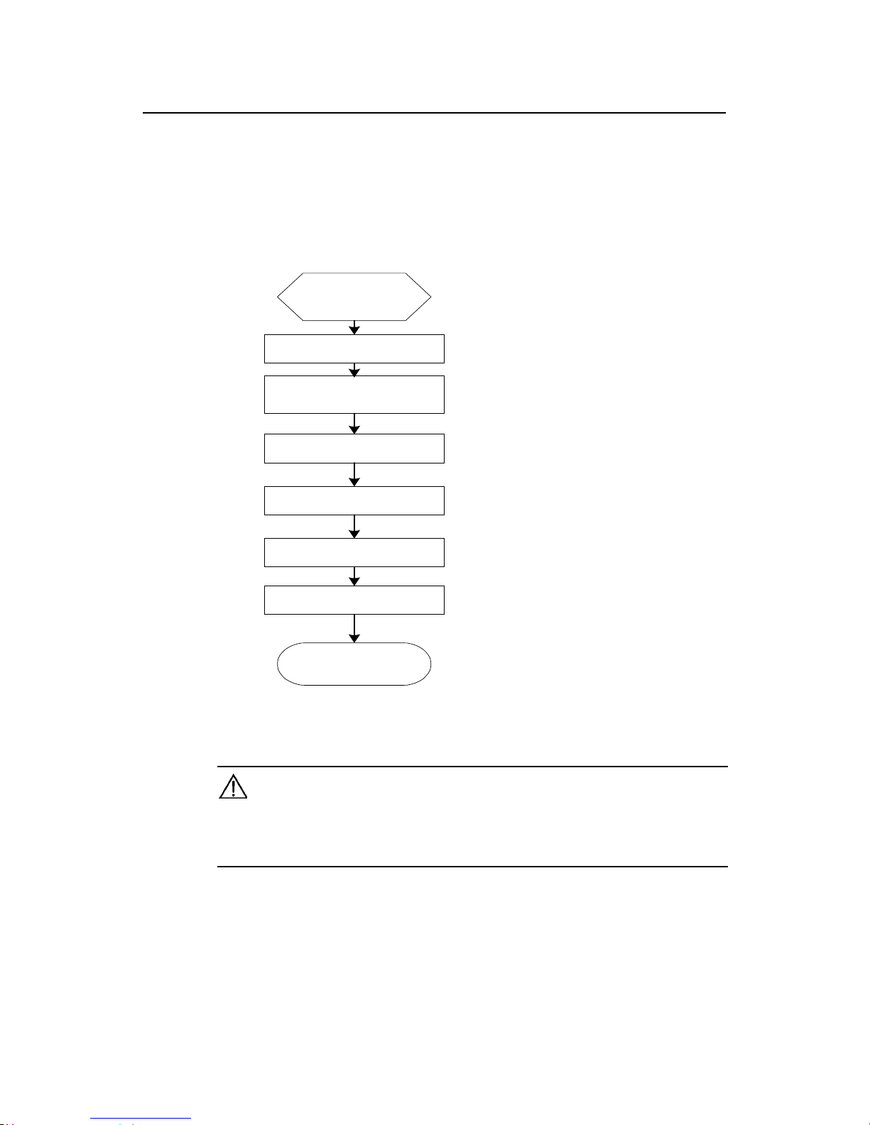
4.1 Installation Flow
Installation completed
Connect the router to the
specified position
Connect various cables
Check after installation
Power on
Configure the router
Preparation and confirmation
Begin to install
Figure 4-1 Flow for installing R2600/3600 series routers
Caution:
Before starting the work described in 4.2 and 4.3, please make sure:
1) You have carefully read Chapter 3 Installation Preparations.
2) The requirements specified in Chapter 3 have been met.
4.2 Mechanical Installation
When you have completed the above work, you can start to install the router.
There are two methods for installing the router depending on the installation position:
Installation Manual
Quidway R2600/3600 Series Modular Routers
Chapter 4
Installation
4-2
z
Installing it in the cabinet
z Placing it on the workbench
4.2.1 Installing the Router in a Cabinet
R2600/3600 series have been d esign ed accor ding to the s ize of the s tand ard 19-inc h
cabinet, and their dimensions are respectively:
Quidway R3680, R3680E: Width x height x depth = 440mm x 86mm x 400mm
Quidway
R2630, R2630E, R2631, R2631E, R3640, and R3640E:
Width x height x depth = 440mm x 43mm x 400mm
Quidway R2620, R2621: Width x height x depth = 440mm x 86mm x 300mm
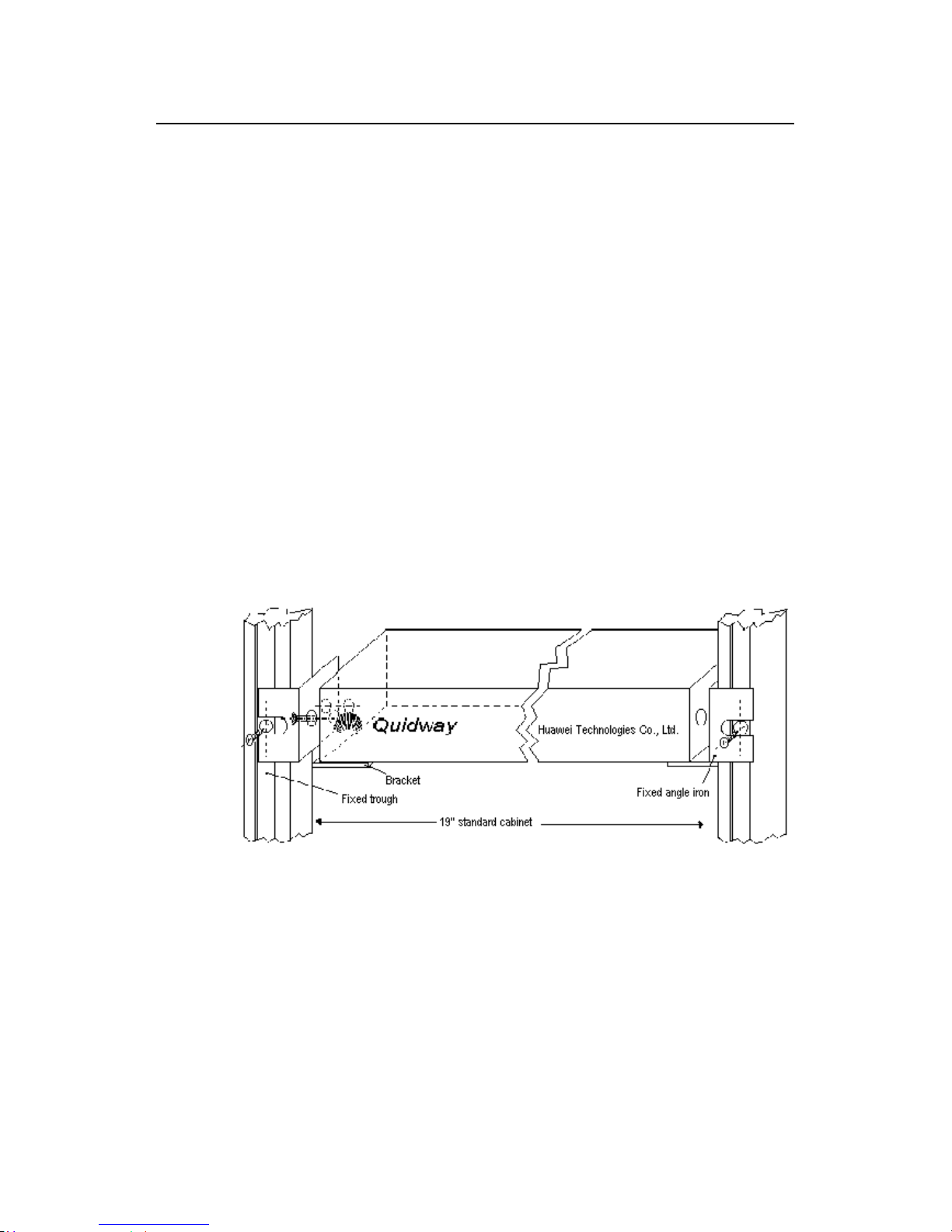
As shown in Figure 4-2, the flow for installing the router is as follows:
Step 1: Check the grounding condition and secureness of the cabinet. Secure the
bracket to both sides of the front/rear panel of the router.
Step 2: Place the router on one of the trays in the cabinet. Move the router to a proper
position along the guide r ail in the cabinet. Leav e an appropriate spac e between the
router and guide rail.
Step 3: Screw the bracket to the fixed guide rail at both sides of the cabinet.
In this way, the router is firmly fixed to the cabinet through the tra y at each slot in the
cabinet and the bracket of the router.
Figure 4-2 Mechanical installation of the Quidway R26/ 36 series
4.2.2 Installing the Router on Workbench
In most of the cases, you do not have a standard 19-inch cabinet. Then, you can place
the routers on clean workbenches. This is a simple operation. During this operation, the
operator:
z Must ensure the stability and good grounding of the workbench.
z
Must reserve a 10cm for heat-dissipation around the router.
z
Do not place any heavy object on the router.
Installation Manual
Quidway R2600/3600 Series Modular Routers
Chapter 4
Installation
4-3
4.3 Power Connection
4.3.1 Connecting Power Cable
R2600/3600 series supp ort the AC/DC power modules ( See Chapter 2 Appearance
and System Features). You can select different types of power modules acc ording to
the specific environment where the router is used.
The AC and DC routers of R2600/3600 series ha ve basically the sam e features and
functions. They differ in their input voltages only.
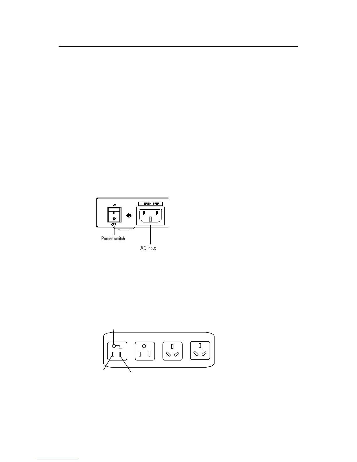
I. AC power and power cable
z AC power
For the power socket of the AC-input router, see Figure 4-3.
Input power:
180 to 240V, 50/60Hz AC (R2630, R2631, R3640, and R3680)
85 to 264V, 50/60Hz AC (R2630E, R2631E, R3640E, R3680E, R2620 and R2621)
Figure 4-3 Power socket of AC-input router
z Recommended AC power socket
A monophase 3-wire power sock et with a neutr al point c onnector, or a specia l power
socket for the computer is recomm ended. T he neutr al po int of the power in a b uild ing
must be reliably grounded. Normally, the neutral point of the power supply system in a
building will have been gr ounded during the construction and wiring. T he user must
make sure that the power supply for the building is earthed.
Neutral point
Zero line
Live line
Figure 4-4 Recommended AC power socket
z
Connecting AC cable
Installation Manual
Quidway R2600/3600 Series Modular Routers
Chapter 4
Installation
4-4
Step 1: Connect one end of the gro und ca ble on the chassis accom pan ying the r out er
to the ground pin on the router’s rear panel, and well ground the other end.
Step 2: After confirming the power switch of the router is turned off, connect one end of
the power line accom pan ying the router t o the p o wer input s ock et on the r outer’s r ear
panel, and connect the other end to the AC socket that delivered with the router.
Step 3: Switch the power switch of the router to the ON position.
Step 4: Check that the power indicator on the rear panel of the router is on. On means
the power cable is correctly connected.
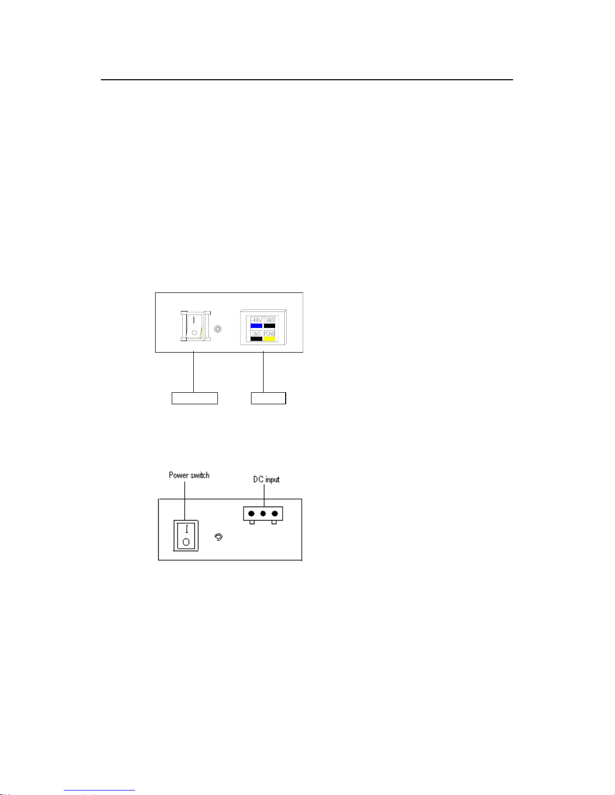
II. DC power and DC cable
z DC power
Input power: -45V to -70V DC
R3640, R3640E, R3680, R3680E, R2630E, and R2631E routers use the DC-input
socket, as shown in Figure 4-5.
Power switch DC-input
Figure 4-5 Power socket of DC-input router (R3640/R3680/R2630E/R2631E/R3640E/R3680E)
R2620 and R2621 routers use the DC-input socket, as shown in Figure 4-6.
Figure 4-6 Power socket of DC-input router (R2620/R2621)
z
Connecting DC cable
Step 1: Connect one end of the gro und ca ble on the chassis accom pan ying the r out er
to the ground pin on the router’s rear panel, and well ground the other end.
Step 2: After confirming the power switch of the router is turned off, connect one end of
the power line accompanying the router to the power socket on the router’s rear panel,
and connect the other end to the –48V DC power of the switch.
Step 3: Switch the power switch of the router to the ON position.
Installation Manual
Quidway R2600/3600 Series Modular Routers
Chapter 4
Installation
4-5
Step 4: Check that the power indicator in the rear panel of the router is on. It is on when
the power cable is correctly connected.
4.3.2 Connecting Ground Cable
Warning:
The normal connection of the router’s ground cable is the primary guarantee for the anti-lightning and
anti-interference capability of the router, so you must connect the ground cable carefully.
The AC input connector of R2600/3600 series comes with an AC noise filter unit,
whose central ground is directly connected with the cabinet, forming the so-called
chassis ground (also called the protection ground). This chassis must be well grounded
so that the induction power and leakage power can be released to the ground to
improve the whole router’s performance to withstand electromagnetic interference.
This ground also provides protection against the lightning and over-voltage likely to be
caused by the external network cable such as the E1 interface and ISDN cables.
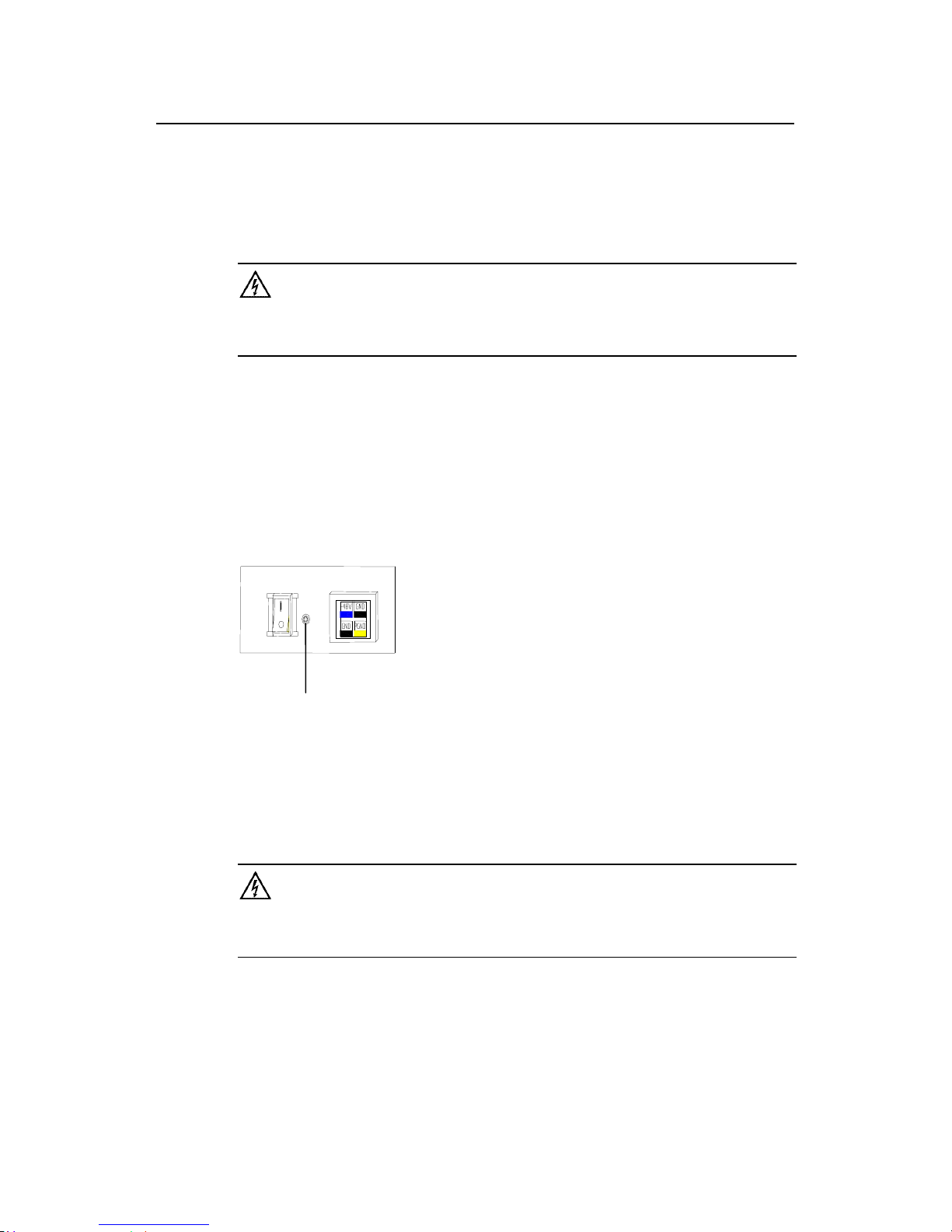
The ground point of the chassis is located near the AC power and switch at the back of
the cabinet, as shown in Figure 4-7. The point shall be connected to the ground.
Ground point
Figure 4-7 Ground point on the chassis
Please connect this point to the gr ound with a gr ound cable, and make sure that the
ground resistance is not gr eater than 5-ohm. If the router is installed in a standard 1 9inch cabinet, then this cabinet should be grounded in the same way.
Warning:
The router must be well grounded for the normal working; otherwise it cannot guard against lightning, and
is likely to cause damage to the router and the far-end equipment connected with this router!
4.4 Connecting Interface Cable on Main Control Panel
Note that Console and AUX interface c annot be use d at the sam e tim e. You can only
choose either of them.
 Loading...