


HUAWEI
®
Quidway R2600/3600 Series Modular Routers
Installation Manual
V200R001

Quidway R2600/3600 Series Modular Routers
Installation Manual
Manual Version
Product Version
BOM
T2-080430-20020202-C-1.0
V200R001
31040430
Copyright © 2001 by Huawei Technologies Co., Ltd.
All Rights Reserved
No part of this docum ent may be reprod uced or transm itted in any form or by any
means without prior written consent of Huawei Technologies Co., Ltd.
Trademarks
®
, HUAWEI®, C&C08, EAST8000, HONET , ViewPoint, INtess, ETS, DM C, SB S ,
TELLIN, InfoLink, Netkey, Quidway, SYNLOCK, Radium,
TELESIGHT, Quidview, NETENGINE, Musa, OptiX, Airbridge, Tellwin, Inmedia,
VRP, DOPRA, iTELLIN are trademarks of Huawei Technologies Co., Ltd.
, M900/M1800,
Notice
The information in this document is subject to change without notice. Although
every effort has been m ade to make this docum ent as accurate, complete, and
clear as possible, Hu awei Technologies assum es no responsibilit y for any errors
that may appear in this document.
Huawei Technologies Co., Ltd.
Address: Huawei Customer Service Building, Kefa Road, Science-based
Industrial Park, Shenzhen, P. R. China
Zip code: 518057
Tel: +86-755-6540036
Fax: +86-755-6540035
Website: http://www.huawei.com
E-mail: support@huawei.com

About This Manual
Contents
The manual consists of 8 chapters that brief the appearance, features, installation,
configuration, maintenance, troubleshooting and function modules of Quidway
R2600/3600 Series Modular Routers.
Chapter 1 is a brief introduction of the Quidway R2600/3600 series modular
routers.
Chapter 2 describes the appearance and system features of Quidway
R2620/R2621, R2630/R2630E, R2631/R2631E, R3640/R3640E and
R3680/R3680E.
Chapter 3 introduces the installation preparations of the routers.
Chapter 4 introduces in detail the installation procedures of the routers.
Chapter 5 is about the startup and configuration of the routers.
Chapter 6 covers the software and hardware maintenance.
Chapter 7 is the troubleshooting procedur es during ins tall ati on.
Chapter 8 depicts the function modules of the routers.
Target Readers
The manual is intended for the following readers:
Installation engineers & technicians
Operation & maintenance personnel
Conventions Used in the Document
Keyboard operation
Format Description
<Key >
Press the key with key name expressed with a pointed
bracket, e.g. <Enter>, <Tab>, <Backspace>, or <A >.
<Key 1 + Key 2>
<Key 1, Key 2> Press the keys in turn, e.g. <Alt, A> means the two keys
[Menu Option]
[Menu 1/Menu 2/Menu 3] Multi-level menu options, e.g. [System/Option/Color setup]
Mouse operation
Click Press the left button or right button quickly (left button by
Double Click Press the left button twice continuously and quic kly .
Drag Press and hold the left button a nd drag it t o a cert ain positi on.
Press the keys concurrently; e.g. <Ctrl+Alt+A> means the
three keys should be pressed concurrently.
should be pressed in turn.
The item with a square bracket indicates the menu option,
e.g. [System] option on the main menu. The item with a
pointed bracket indicates the functional button option, e.g.
<OK> button on some interface.
on the main menu indicates [Color Setup] on the menu
option of [Option], which is on the menu option of [System].
Action Description
default).
Symbol
Some distinct s ymbols are em ployed in the manual to indicate the special notic e that
should be taken for the operation. The symbols are:
Caution, Notice, Warning, Danger: Notify the special attentio n that should be
given to the operation.
Note, Prompt, Tip, Thought: Give further necessary supplement or explanatio n
for the operation description.

Installation Manual
Quidway R2600/3600 Series Modular Routers Table of Contents
Table of Contents
Chapter 1 Introduction................................................................................................................. 1-1
1.1 Quidway R2600/3600 Series Modular Routers ................................................................ 1-1
1.2 Models .............................................................................................................................. 1-1
1.3 Function Modules Supported............................................................................................ 1-1
1.4 Product Features .............................................................................................................. 1-2
1.5 Typical Application............................................................................................................ 1-3
Chapter 2 Appearance and System Features............................................................................ 2-1
2.1 Quidway R2620/R2621..................................................................................................... 2-1
2.1.1 Appearance............................................................................................................ 2-1
2.1.2 Indicators on Panel ................................................................................................ 2-2
2.1.3 System Description ................................................................................................ 2-2
2.2 Quidway R2630/R2630E.................................................................................................. 2-3
2.2.1 Appearance............................................................................................................ 2-3
2.2.2 Indicators on Panel ................................................................................................ 2-3
2.2.3 System Description ................................................................................................ 2-4
2.3 Quidway R2631/R2631E.................................................................................................. 2-5
2.3.1 Appearance............................................................................................................ 2-5
2.3.2 Indicators on Panels............................................................................................... 2-5
2.3.3 System Description ................................................................................................ 2-6
2.4 Quidway R3640/R3640E.................................................................................................. 2-6
2.4.1 Appearance............................................................................................................ 2-6
2.4.2 Indicators on Panel ................................................................................................ 2-7
2.4.3 System Description ................................................................................................ 2-7
2.5 Quidway R3680/R3680E.................................................................................................. 2-8
2.5.1 Appearance............................................................................................................ 2-8
2.5.2 Indicators on Panel ................................................................................................ 2-9
2.5.3 System Description ................................................................................................ 2-9
Chapter 3 Installation Preparations............................................................................................3-1
3.1 Safety Recommendations ................................................................................................. 3-1
3.2 Installation Conditions....................................................................................................... 3-1
3.2.1 Temperature and Humidity Requirements............................................................. 3-1
3.2.2 Cleanness Requirements....................................................................................... 3-2
3.2.3 ESD-Preventive Requirements.............................................................................. 3-3
3.2.4 Anti-interference Requirements ............................................................................. 3-3
3.2.5 Lightning Protection Requirements........................................................................ 3-3
3.2.6 Workbench Requirements...................................................................................... 3-4
3.3 Tools and Devices Required............................................................................................. 3-4
i

Installation Manual
Quidway R2600/3600 Series Modular Routers Table of Contents
Chapter 4 Installation................................................................................................................... 4-1
4.1 Installation Flow ................................................................................................................4-1
4.2 Mechanical Installation ..................................................................................................... 4-1
4.2.1 Installing the Router in a Cabinet........................................................................... 4-2
4.2.2 Installing the Router on Workbench....................................................................... 4-2
4.3 Power Connection............................................................................................................. 4-3
4.3.1 Connecting Power Cable ....................................................................................... 4-3
4.3.2 Connecting Ground Cable...................................................................................... 4-5
4.4 Connecting Interface Cable on Main Control Panel .........................................................4-5
4.4.1 Connecting Console Port....................................................................................... 4-6
4.4.2 Connecting AUX Port............................................................................................. 4-7
4.5 Connecting Interface Cable.............................................................................................. 4-9
4.6 Installation Check .............................................................................................................4-9
Chapter 5 Startup and Configuration ......................................................................................... 5-1
5.1 Starting the Router............................................................................................................ 5-1
5.1.1 Setting up Configuration Environment ................................................................... 5-1
5.1.2 Powering on Router ...............................................................................................5-4
5.1.3 Starting Router ....................................................................................................... 5-5
5.1.4 Configuring Router via Setup................................................................................. 5-6
5.2 Configuration Basic.......................................................................................................... 5-8
5.2.1 Basic Configuration Mode...................................................................................... 5-8
5.2.2 Help........................................................................................................................ 5-9
Chapter 6 Maintenance................................................................................................................ 6-1
6.1 Software Maintenance...................................................................................................... 6-1
6.1.1 BOOT Menu ........................................................................................................... 6-1
6.1.2 Upgrading Software via XModem .......................................................................... 6-2
6.1.3 Upgrading Main Program via TFTP ....................................................................... 6-4
6.1.4 Uploading and Downloading Files via FTP............................................................ 6-6
6.1.5 Password Lost........................................................................................................ 6-8
6.2 Hardware Maintenance..................................................................................................... 6-8
6.2.1 Opening the Chassis.............................................................................................. 6-9
6.2.2 Replacing the SIMM............................................................................................. 6-10
6.2.3 Replacing BOOTROM.......................................................................................... 6-14
6.2.4 Closing the Chassis ............................................................................................. 6-16
6.2.5 Replacing the Function Modules.......................................................................... 6-17
Chapter 7 Troubleshooting ......................................................................................................... 7-1
7.1 Power System................................................................................................................... 7-1
7.2 Configuration System .......................................................................................................7-1
Chapter 8 Function Modules....................................................................................................... 8-1
8.1 Introduction to Function Modules...................................................................................... 8-1
8.2 Arrangement of the Router Slots...................................................................................... 8-1
ii

Installation Manual
Quidway R2600/3600 Series Modular Routers Table of Contents
8.3 Function Modules Installation........................................................................................... 8-3
8.4 Function Modules Troubleshooting................................................................................... 8-5
8.5 1FE/2FE Module............................................................................................................... 8-5
8.5.1 Introduction.............................................................................................................8-5
8.5.2 Appearance............................................................................................................ 8-6
8.5.3 Interface Attributes................................................................................................. 8-7
8.5.4 Indicators on Panel ................................................................................................ 8-7
8.5.5 Interface Cable....................................................................................................... 8-8
8.5.6 Connecting Interface Cable.................................................................................. 8-10
8.6 2SA/4SA Module.............................................................................................................8-11
8.6.1 Introduction........................................................................................................... 8-11
8.6.2 Appearance.......................................................................................................... 8-13
8.6.3 Interface Attributes............................................................................................... 8-14
8.6.4 Indicators on Panel .............................................................................................. 8-15
8.6.5 Interface Cable..................................................................................................... 8-16
8.6.6 Connecting Interface Cable.................................................................................. 8-22
8.7 8AS/16AS Module........................................................................................................... 8-24
8.7.1 Introduction........................................................................................................... 8-24
8.7.2 Appearance.......................................................................................................... 8-25
8.7.3 Interface Attributes............................................................................................... 8-25
8.7.4 Indicators on Panel .............................................................................................. 8-26
8.7.5 Interface Cable..................................................................................................... 8-27
8.7.6 Connecting Interface Cable.................................................................................. 8-32
8.8 1E1/2E1/4E1 Module...................................................................................................... 8-33
8.8.1 Introduction........................................................................................................... 8-33
8.8.2 Appearance.......................................................................................................... 8-34
8.8.3 Interface Attributes............................................................................................... 8-35
8.8.4 Indicators on Panel .............................................................................................. 8-36
8.8.5 Interface Cable..................................................................................................... 8-37
8.8.6 Internal DIP Switches........................................................................................... 8-39
8.8.7 Connecting Interface Cable.................................................................................. 8-41
8.9 4BS Module .................................................................................................................... 8-43
8.9.1 Introduction........................................................................................................... 8-43
8.9.2 Appearance.......................................................................................................... 8-43
8.9.3 Interface Attributes............................................................................................... 8-44
8.9.4 Indicators on Panel .............................................................................................. 8-45
8.9.5 Interface Cable..................................................................................................... 8-46
8.9.6 Connecting Interface Cable.................................................................................. 8-46
8.10 2S1B Module ................................................................................................................ 8-46
8.10.1 Introduction......................................................................................................... 8-46
8.10.2 Appearance........................................................................................................ 8-47
8.10.3 Interface Attributes.............................................................................................8-47
iii

Installation Manual
Quidway R2600/3600 Series Modular Routers Table of Contents
8.10.4 Indicators on Panel ............................................................................................ 8-48
8.10.5 Interface Cable................................................................................................... 8-48
8.10.6 Connecting Interface Cable................................................................................ 8-49
8.11 2FXS/2FXO/2E&M Module........................................................................................... 8-50
8.11.1 Introduction......................................................................................................... 8-51
8.11.2 Appearance........................................................................................................ 8-51
8.11.3 Interface Attributes.............................................................................................8-51
8.11.4 Indicators on Panel ............................................................................................ 8-52
8.11.5 Interface Cable................................................................................................... 8-53
8.11.6 Connecting Interface Cable................................................................................ 8-55
8.12 4FXS/4FXO/4E&M Module........................................................................................... 8-56
8.12.1 Introduction......................................................................................................... 8-56
8.12.2 Appearance........................................................................................................ 8-56
8.12.3 Interface Attributes.............................................................................................8-57
8.12.4 Indicators on Panel ............................................................................................ 8-57
8.12.5 Interface Cable................................................................................................... 8-58
8.12.6 Connecting Interface Cable................................................................................ 8-58
8.13 8LSA Module ................................................................................................................ 8-59
8.13.1 Introduction......................................................................................................... 8-59
8.13.2 Appearance........................................................................................................ 8-60
8.13.3 Interface Attributes.............................................................................................8-60
8.13.4 Indicators on Panel ............................................................................................ 8-61
8.13.5 Interface Cable................................................................................................... 8-61
8.13.6 Connecting Interface Cable................................................................................ 8-66
8.14 E1VI Module .................................................................................................................8-67
8.14.1 Introduction......................................................................................................... 8-67
8.14.2 Appearance........................................................................................................ 8-67
8.14.3 Interface Attributes.............................................................................................8-67
8.14.4 Indicators on Panel ............................................................................................ 8-68
8.14.5 Interface Cable................................................................................................... 8-68
8.14.6 Connecting Interface Cable................................................................................ 8-70
iv

Installation Manual
Quidway R2600/3600 Series Modular Routers
Chapter 1 Introduction
1.1 Quidway R2600/3600 Series Modular Routers
Quidway R2600/3600 series modular routers (referred to as R2600/3600 series
hereafter) are independe ntly developed b y Huawei for ent erprise net works. T hey can
be used as core routers in medium- and small-sized Intranets, or as access servers at
some major branch offices.
With a modular structure, R2600/3600 series adopt the Versatile Routing Platform
(VRP), a proprietar y software platform of Huawei, and incorporate high-performanc e
processor, bus technology and fast routing policy. While providing a large array of
service interfaces, it can als o be used together with Quidway
R2500 series, and Quidway NetEngine08/16E series routers to provide overall
solutions for large- and medium-sized industry users such as telecom, private network
carrier, ISP, finance, tax, police, and railway , etc. At the same time, its function modules
comply with various network standards. So R2600/3600 series are in the best interests
to protect your existing investments while guaranteeing interoperability at various
levels with major products on the global market.
R1600 series, Quid way
Chapter 1
Introduction
1.2 Models
R2600/3600 series includ e: R2620, R2621, R263 0, R2631, R3640, R36 80, R2630E,
R2631E, R3640E and R3680E:
z R2620 and R2621 adopt Power PC 8240 CPU main b oard, but they differ from
z R2630E, R2631E, R3640E and R3680E differ from R2630, R2631, R3640 and
R2600/3600 series provide different number of module slots:
z Quid way R2620 provides on e 10/100Mbps Ethernet inter faces, two s ynchronous
z Quidway R2621 provides two 10/100Mbps Ethernet interface, two synchronous
Quidway R2630/R2630E prov ides one 10/100Mbps Fast Ethernet interf ace and
z
z Quidwa y R2631/R2631E prov ides two 10/100 Mbps Fast Ethernet int erfaces and
z Quidway R3640/R3640E provides four standard PCI slots.
Quidway R3680/R3680E provides eight standard PCI slots.
z
other R2600/3600 ser ies routers in that they have t wo fixed synchronous serial
interfaces besides the fixed Ethernet interfaces.
R3680 in that the f ormer adopt Power PC 82 40 CPU main board and the latter
adopt Pentium CPU main board. They have the same software features and
functional implem entations. The interf ace modules used b y them are completel y
compatible, but the former are mor e powerful in their proces sing capability and
packet forwarding performance.
serial interfaces, and two standard PCI slots.
serial interfaces and two standard PCI slots.
three standard PCI slots.
three standard PCI slots.
1.3 Function Modules Support ed
R2600/3600 series support the following function modules:
1-1

Installation Manual
Quidway R2600/3600 Series Modular Routers
z 1-port 10/100Base-TX Fast Ethernet interface module (1FE)
2-port 10/100Base-TX Fast Ethernet interface module (2FE)
z
z 2-port high-speed sync/async serial interface module (2SA)
z 4-port high-speed sync/async serial interface module (4SA)
z 2-port sync/async serial interface+1 port ISDN BRI S/T interface module (2S1B)
1-port channelized cE1/PRI interface module (1E1)
z
z 2-port channelized cE1/PRI interface module (2E1)
z 4-port channelized cE1/PRI interface module (4E1)
4-port ISDN BRI S/T interface module (4BS)
z
z 8-port async serial interface module (8AS)
z 16-port async serial interfac e module (1 6AS)
z 2-port voice interface module (FXS interface) (2FXS)
2-port voice interface module (FXO interface) (2FXO)
z
z 2-port voice interface module (E&M interface) (2E&M)
4-port voice interface module (FXS interface) (4FXS)
z
z 4-port voice interface module (FXO interface) (4FXO)
z 4-port voice interface module (E&M interface) (4E&M)
z 8-port low-speed sync/async serial interface module (8LSA)
z 1-port voice interface module (E1 interface) (E1VI)
When buying the R2600/3600 series, you can select proper function modules based on
your requirements, following the selection rules below:
z Multiple modules of the same type can be configured in the router.
z The module can be configured to any slot.
z The interface cable is directly related with specific module.
For details about th e f unc tion modules and interf ace c ab les , p leas e r ef er to Ch apter 8
Function Modules.
Chapter 1
Introduction
1.4 Product Features
I. Powerful backup function
R2600/3600 series supp ort interf ace bac k up, link back up and rout e back up f unctions,
of which the backup can be between DDN l ine and dialup line, bet ween DDN line and
virtual link, or between dialup lines. It supports mutual backup between such networks
as DDN, X.25, PSTN, ISDN, and f ram e relay. It also supports HSRP, an d t wo routers
can be backup for each other.
II. Solution to remote office
R2600/3600 series provide solution to high-density remote office. It supports a
maximum of 112 analog dialup users (R3680/R3680E) or 28 I SDN BRI dialup users
(R3680/3680E).
III. E1/cE1 and cE1/PRI compatible
R2600/3600 series pro vide cE1 (Channelized E1) access, and the cE1 interface is
compatible with the E1 interface. At the same time, the ISDN PRI function can be
implemented on the cE1 interface.
IV. High density interfaces
R2600/3600 series support up to 28 2Mbit/s sync serial interface (R3680/R3680E),
which can connect to such networks as DDN, frame relay, and X.25.
1-2

Installation Manual
Quidway R2600/3600 Series Modular Routers
V. Voice-related support features
R2600/3600 series suppor t voice features. It can provi de the following voice m odule
types for different users: 2FXS, 2FX O, 2E&M, 4FXS, 4FX O, 4E&M and E 1VI, among
which:
z 2FXS and 4FXS modules are used to connect analog phones.
2FXO and 4FXO modules are used to connect loop trunks in the switching system.
z
z 2E&M and 4E&M modules are used for the connection of E&M trunks in the
switching syst em.
z E1VI module is used for the connection of E1 trunks in the switching system.
The voice modules of R2600/3 600 series support m ultiple codin g algorithms s uch as
G.711, G.723 and G.729. It also supports H. 323 pr otoc ol stack and GK i nterfac e, an d
demonstrates succes sful interoper ability with the equipment f rom such VoIP suppliers
as Cisco, AudioCodec, Motorola and VocalTec.
VI. Flexible memory configuration
Users can select the memory capacity flexibly according to system configuration,
number of function m odules, and performanc e requirement. Up to 256M B memor y is
supported.
VII. Others
Chapter 1
Introduction
R2600/3600 series support 100Mbps fast access to the local network and flexible
networking configuration.
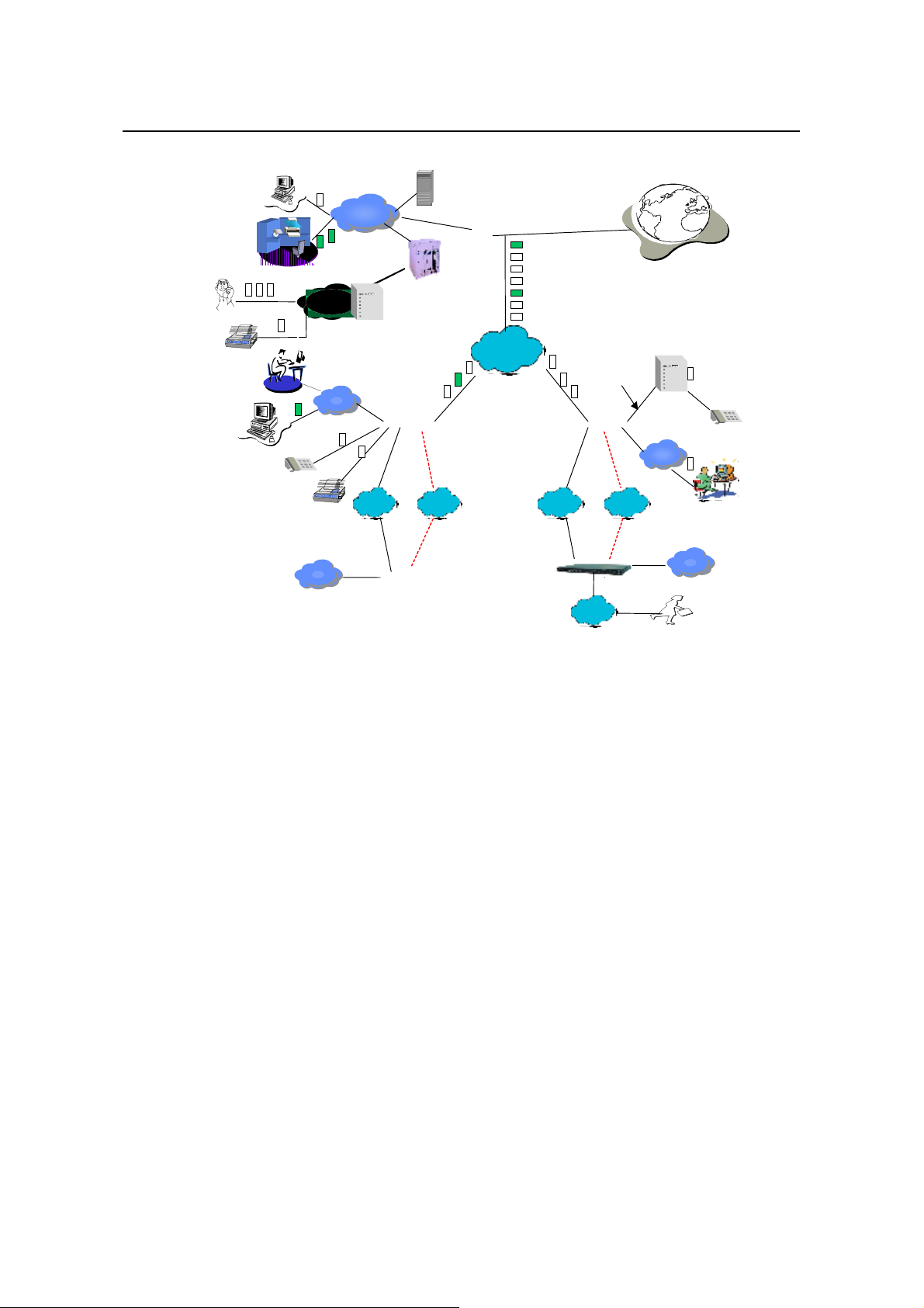
1.5 Typical Application
1-3
Installation Manual
Quidway R2600/3600 Series Modular Routers
Chapter 1
Introduction
Phone
FAX
Quidway
Server
E1 trunk
PBX
Branch Intranet
LAN
LAN
Level-3 Intranet
LAN
routers enterprise network solution
GK
LAN
A8010Refiner
办公
办公
办公办公
Central network
LAN
PBX
LAN
X25
DDN/FR/
Quidway
Quidway
3600
R2600
/
PSTN/
ISDN
1602/1603/1604
The red dotted line stands for backup line.
Quidway
DDN/FR
QuidwayR2600/3600
LAN
LAN
3680
AT0/E&M
DDN/FR/
X25
PSTN/
ISDN
Quidway2511/2509/4001
ISDN/
PSTN
representative office
Internet
LAN
Level-3 Intranet
LAN
LAN
Branch Intranet
Figure 1-1 Typical application of Quidway R2600/3600 series routers
1-4
Installation Manual
Quidway R2600/3600 Series Modular Routers
Appearance and System Features
Chapter 2 Appearance and Syste m Features
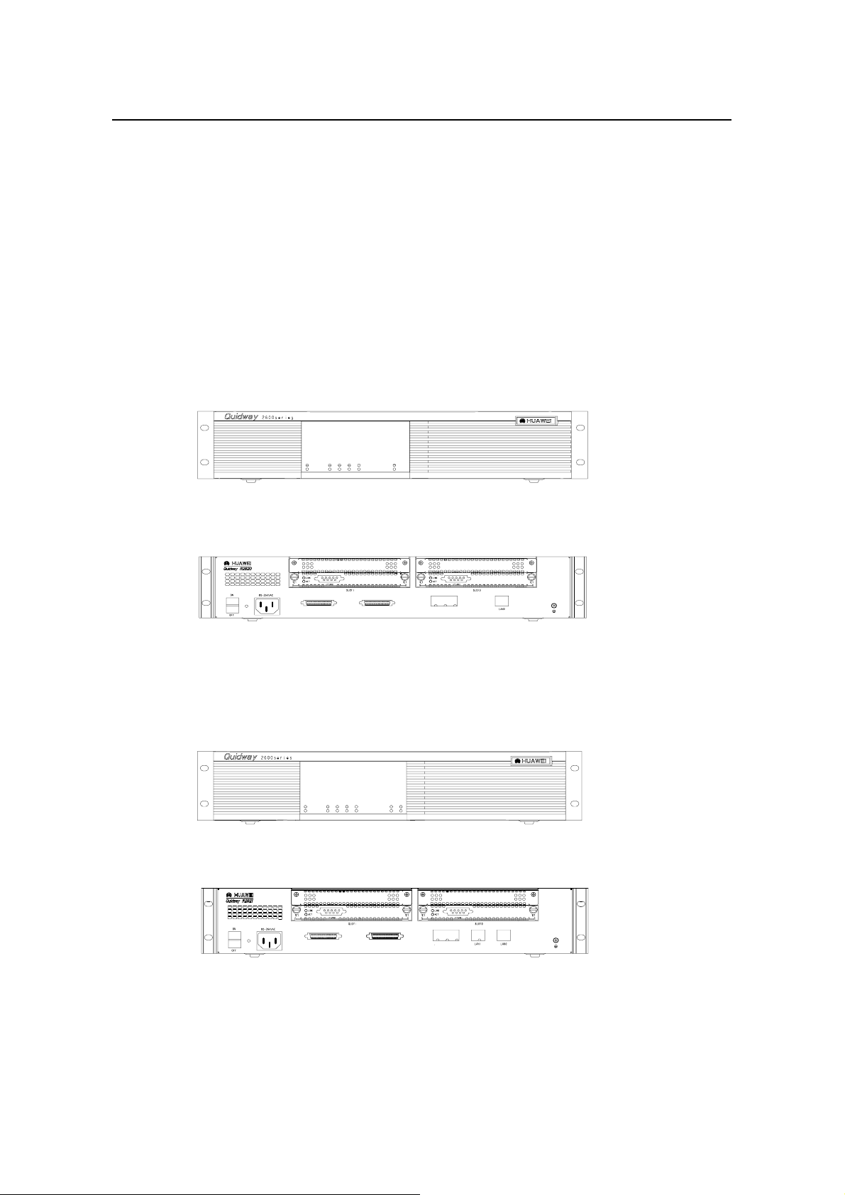
2.1 Quidway R2620/R2621
2.1.1 Appearance
I. Appearance of R2620
The front panel and rear panel of R2620 are shown in the following figures.
SLOT0 SLOT1 WAN0 WAN1 LAN0
POWER
SYSTEM
READY
ACTIVE
LINK
ACTIVE
Chapter 2
Figure 2-1 Front panel of R2620
WAN1 WAN0
CONSOLE
AUX
Figure 2-2 Rear panel of R2620
II. Appearance of R2621
The front panel and rear panel of R2621 are shown in the following figures.
SLOT0 SLOT1 WAN0 WAN1 LAN0 LAN1PO
POWER
SYSTEM
READY
ACTIVE
LINK
ACTIVE
Figure 2-3 Front panel of R2621
Figure 2-4 Rear panel of R2621
WAN0WAN0WAN1
AUX
CONSOLE
2-1
Installation Manual
Quidway R2600/3600 Series Modular Routers
2.1.2 Indicators on Panel
The meanings of indicators on the front panel of R2620/R2621 are shown in the
following table.
Table 2-1 Meanings of indicators on the front panel of R2620/R2621
Indicator Meaning
POWER System power indicator: Off means power is off. On means power is on.
SYSTEM
READY
ACTIVE
LINK Off means the LAN line is not connected. On means the LAN line is connected.
SLOT0-SLOT1 Indicating the corresponding slot number.
WAN0-WAN1 Indicating the corresponding WAN interface number.
LAN0, LAN1 (only for R2621) Indicating the corresponding Ethernet interface number.
The attributes of WAN0 and WAN1 interfaces of R2620/2621 are described in the
following table.
Chapter 2
Appearance and System Features
Hardware status indicator. Blinking means system is normal. Always on/off
means system is abnormal.
Module indicator. On means the modul e of th e current s lot is wo rking normal ly.
Off means the module is abnormal or no module is installed in the current slot.
Blinking means data is being r eceived and transmitted by the module in the
current slot. Off means no data is being received or transmitted by the module in
the corresponding slot.
Table 2-2 Attributes of WAN0 and WAN1 interfaces of R2620/2621
Attribute Synchronous
Connector DB-50
Interface standards and
operating mode
Minimum baud rate (bit/s) 1200 1200
Maximum baud rate (bit/s) 64K 2.048M
Services supported
Protocols supported
2.1.3 System Description
The table below sho ws the basic configuratio ns, dimensions, opera ting environm ent,
etc. of R2620 and R2621.
V.24 V.35
DTE
DCE
---Modem dial-up
---Backup
---Terminal access service
---PPP
---MP
---LAPB
---X.25
---HDLC
---SDLC
---Frame Relay
DTE
DCE
2-2
Installation Manual
Quidway R2600/3600 Series Modular Routers
Table 2-3 System description of R2620/R2621
Item Description of R2620 Description of R2621
Slot
CPU Power PC 8240 200MHz
BOOT ROM 512KB 512KB
SDRAM
FLASH 8MB
Dimensions Width x Height x Depth = 440mm x 86mm x 300mm
Weight 5kg
Input voltage
Max. Power 70W
Operating temperature 0 to 40OC
Operating humidity 10 to 90% non-condensing
Note:
Dynamic memory (DRAM/SDRAM) works as main memory.
FLASH stores system programs.
Chapter 2
Appearance and System Features
A maximum of 2 function modules can be configured according to
requirement.
Default: 32MB
Max.: 128MB
AC: 85V to 264V 50/60Hz
DC: -40V to -75V
2.2 Quidway R2630/R2630E
2.2.1 Appearance
For R2630 and R2630E, their f ront panels and rear pa nels are ver y similar, see their
outlook as the following (take R2630 as an example).
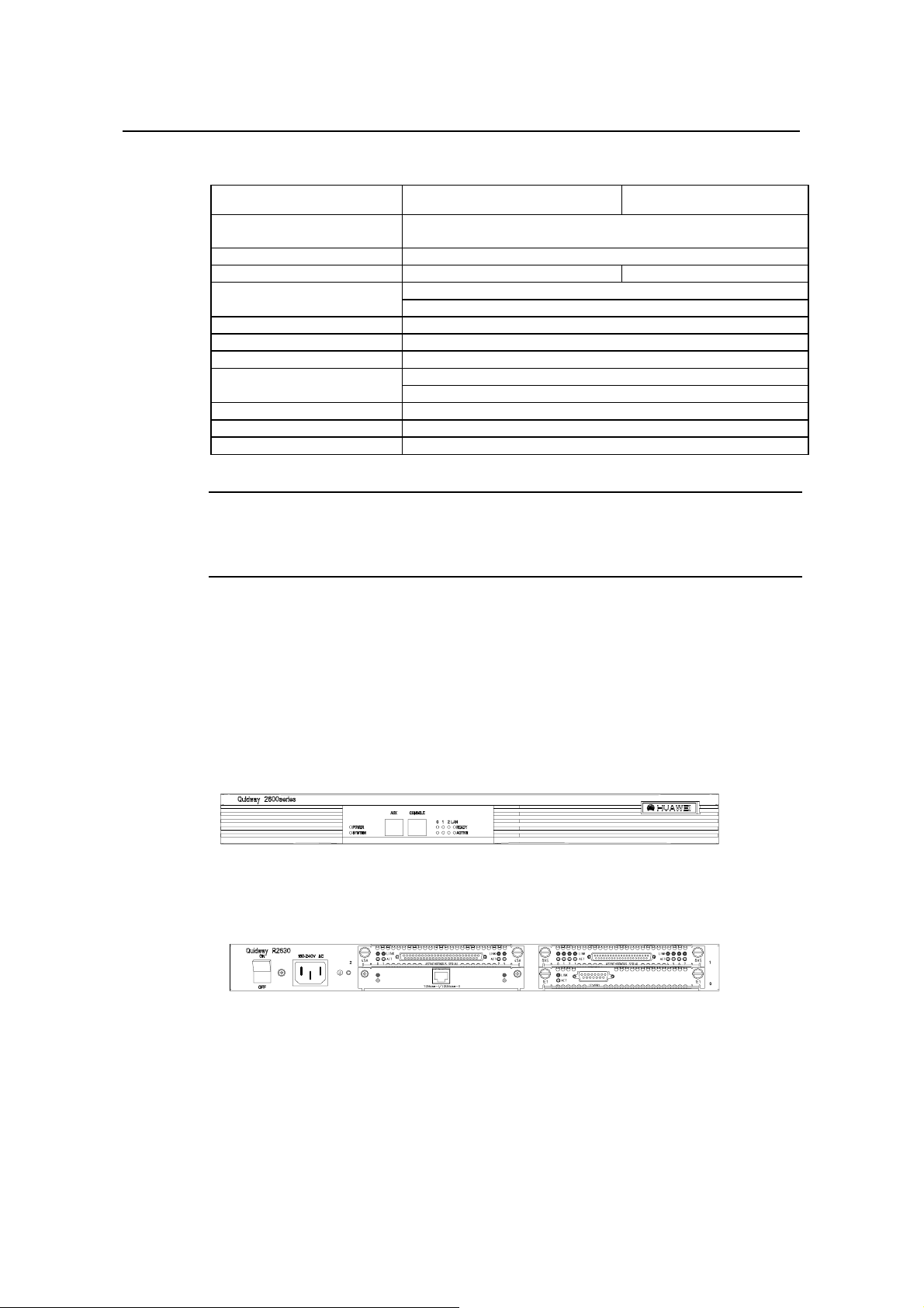
Figure 2-5 Front panel of R2630
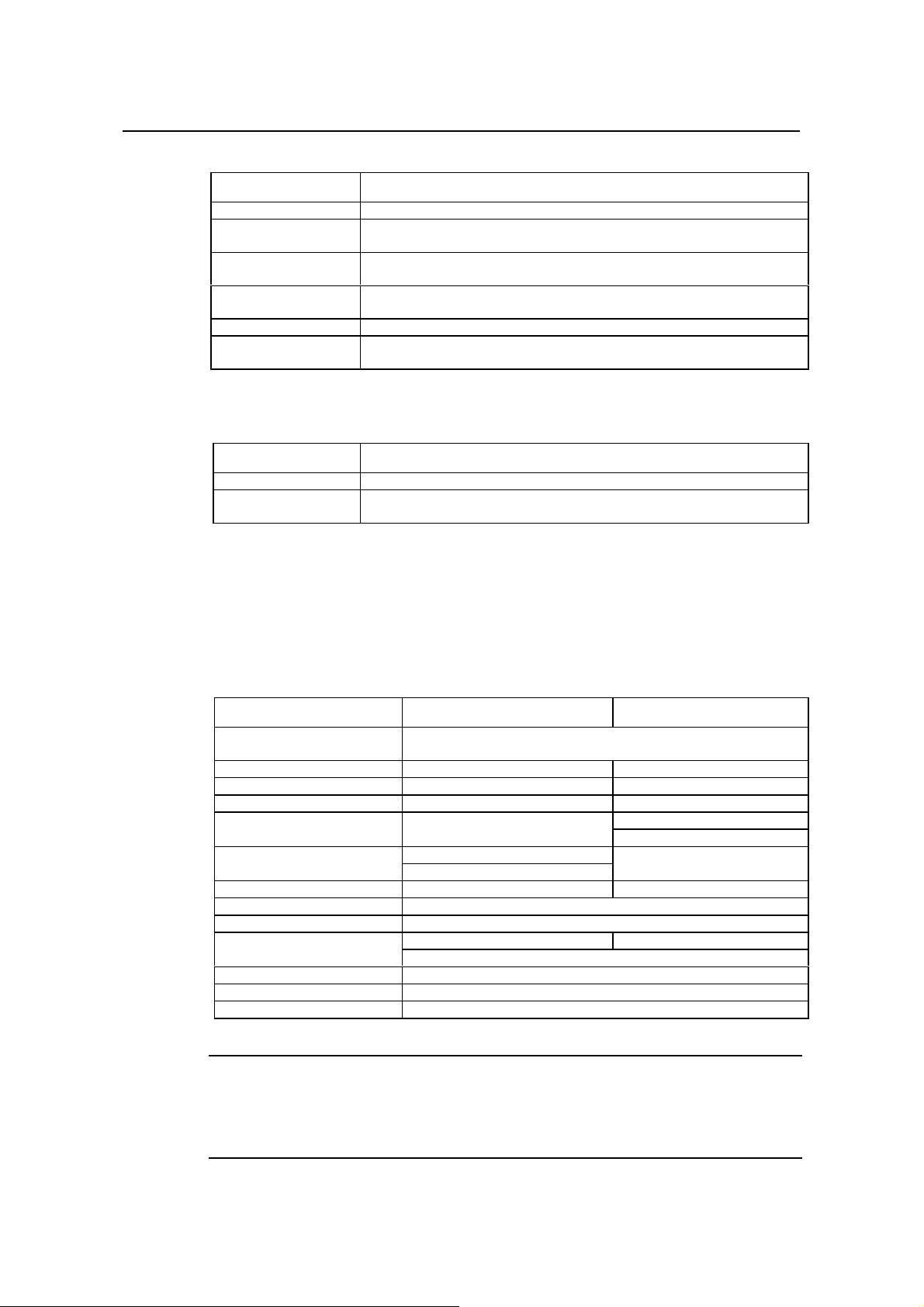
Figure 2-6 Rear panel of R2630
2.2.2 Indicators on Panel
The meanings of indicators on the front and rear panels of R2630/R2630E are shown in
the following tables.
2-3
Installation Manual
Quidway R2600/3600 Series Modular Routers
Table 2-4 Meanings of indicators on the front panel of R2630/R2630E
Indicator Meaning
POWER System power indicator: Off means power is off, On means power is on.
SYSTEM
READY
ACTIVE
0 - 2 Indicating the slot number.
LAN
Hardware status indicator. Blinking means the system runs normally. Always on/off
means the system is abnormal.
Module status indicator: On means the module in corresponding slot runs normall y.
Off means the module runs abnormally or no module is installed.
Blinking means data is being received or transmitted by the module in the
corresponding slot. Off means no data is being received or transmitted
Ethernet interface indic ator: Green means the interface is normal. Bli nking yellow
means data is being received and transmitted over the Ethernet.
Table 2-5 Meanings of indicators on the rear panel of R2630/R2630E
Indicator Meaning
LINK Off means the Ethernet link is not connected. On means the link is connected.
ACTIVE
Off means no data is being received and transmitted by the Ethernet interface.
Blinking means data is being received or transmitted.
Chapter 2
Appearance and System Features
2.2.3 System Description
The following table shows the basic configuration, dimensions, operating environment,
etc. of R2630 and R2630E.
Table 2-6 System description of R2630/R2630E
Item Description of R2630 Description of R2630E
Slot
CPU Pentium 133MHz Power PC 8240 200MHz
NVRAM 128KB 128KB
BOOTROM 512KB 512KB
SDRAM None
DRAM
FLASH 8MB
Dimensions Width x Height x Depth = 440mm x 43mm x 400mm
Weight 8kg
Input voltage
Max. power 80W
Operating temperature 0 to 40OC
Operating humidity 10 to 90% non-condensing
A maximum of 3 interface modules can be configured according to
requirement.
Default: 64MB
Max.: 256MB
Default: 32MB
Max.: 128MB
AC: 160 to 240V 50/ 60Hz AC: 85 to 264V 50/60Hz
DC: -40 to -75V
None
Note:
Dynamic memory (DRAM/SDRAM) works as main memory.
FLASH stores system programs.
NVRAM stores configuration files.
2-4
Installation Manual
Quidway R2600/3600 Series Modular Routers
2.3 Quidway R2631/R2631E
2.3.1 Appearance
For R2631 and R2631E, their f ront panels and rear pa nels are ver y similar, see their
outlook as the following (take R2631 as an example).
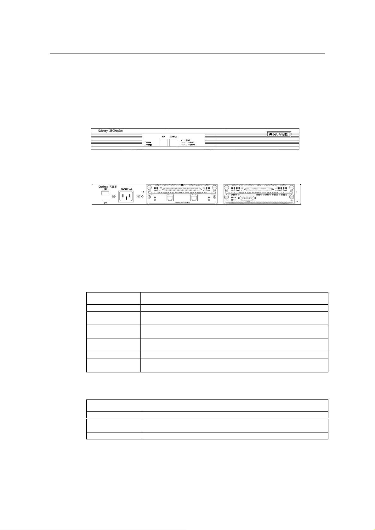
Figure 2-7 Front panel of R2631
Figure 2-8 Rear panel of R2631
Chapter 2
Appearance and System Features
2.3.2 Indicators on Panels
The meanings of ind icators on the front and rear pane ls of R2631 and R2631E are
shown in the following tables.
Table 2-7 Meanings of indicators on the front panel of R2631/R2631E
Indicator Meaning
POWER System power indicator: Off means power is off. On means power is on.
SYSTEM
READY
ACTIVE
0 - 2 Position of the corresponding slots.
LAN
Table 2-8 Meanings of indicators on the rear panel of R2631/R2631E
Indicator Meaning
LINK Off means the Ethernet link is not connected. On means the link is connected.
ACTIVE
0 - 1 Corresponding port number.
Hardware status indicator: Blinking means system is normal. Always on/off means the
system is abnormal.
Module status indicator: On means the modul e runs normally in the current slot. Off
means the module runs abnormally or no module is installed.
Blinking means data is being received or transmitted by the module in the current slot. Off
means no data is being received or transmitted by the module in the current slot.
Ethernet interface indicator. Green means the interface is normal. Blinking yellow means
that data is being received or transmitted over the Ethernet.
Off means no data is being received or transmitted by the Ethernet interface. Blinking
means data is being received or transmitted.
2-5

Installation Manual
Quidway R2600/3600 Series Modular Routers
2.3.3 System Description
The following table shows the basic configuration, dimensions, operating environment,
etc. of R2631 and R2631E.
Table 2-9 System description of R2631/R2631E
Item Description of R2631 Description of R2631E
Slot
CPU Pentium133MHz Power PC 8240 200MHz
NVRAM 128KB
BOOT ROM 512KB
SDRAM None
DRAM
FLASH 8MB
Dimensions Width x Height x Depth = 440mm x 43mm x 400mm
Weight 8kg
Input voltage
Max. power (with 3 modules) 80W
Operating temperature 0 to 40OC
Operating humidity 10 to 90% non-condensing
Chapter 2
Appearance and System Features
A maximum of 3 interface modules can be configured according to
requirement.
Default: 64MB
Max.: 256MB
Default: 32MB
Max.: 128MB
AC: 160 to 240V 50/ 60Hz AC: 85 to 264V 50/ 60Hz
DC: -40V to -75V
None
Note:
Dynamic memory (DRAM/SDRAM) works as main memory.
FLASH stores system programs.
NVRAM stores configuration files.
2.4 Quidway R3640/R3640E
2.4.1 Appearance
For R3640 and R3640E, their f ront panels and rear pa nels are ver y similar, see their
outlook as the following (take R3640 as an example)
Figure 2-9 Front panel of R3640
2-6
Installation Manual
Quidway R2600/3600 Series Modular Routers
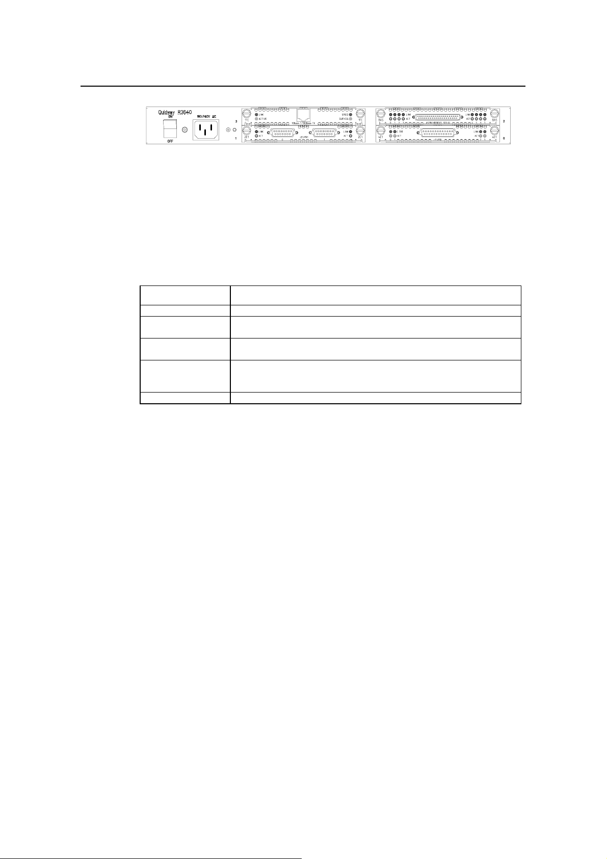
Figure 2-10 Rear panel of R3640
2.4.2 Indicators on Panel
The meanings of indicators on the front panel of R3640/R3640E are shown in the
following table.
Table 2-10 Meanings of indicators on the front panel of R3640/R3640E
Indicator Meaning
POWER System power indicator: Off means power is off. On means power is on.
SYSTEM
READY
ACTIVE
0 - 3 Position of corresponding slots.
Hardware status indicator: Blinking means system is normal. Always on/off means
system is abnormal.
Module indicator. On means the module of the current slot is working normally. Off
means the module is abnormal or no module is installed in the current slot.
Blinking means data is being received and transmitted by the module in the current
slot. Off means no data is being received or transmitted by the module in the current
slot.
Chapter 2
Appearance and System Features
2.4.3 System Description
The following table shows the basic configurations, dimensions, operating environment,
etc. of R3640 and R3640E.
2-7

Installation Manual
Quidway R2600/3600 Series Modular Routers
Table 2-11 System Description of R3640/R3640E
Item Description of R3640 Description of R3640E
Slot A maximum of 4 function modules can be configured according to requirement.
Processor Pentium 133MHz Power PC 8240 250MHz
NVRAM 128KB
BOOT ROM 512KB
SDRAM None
DRAM
FLASH 8MB
Dimensions Width x Height x Depth = 440mm x 43mm x 400mm
Weight 8kg
Input voltage
Max. power (with 4 modules) 80W
Operating temperature 0 to 40OC
Operating humidity 10 to 90% non-condensing
Note:
Dynamic memory (DRAM/SDRAM) works as main memory.
FLASH stores system programs.
NVRAM stores configuration files.
Appearance and System Features
Default: 128MB
Max.: 256MB
Default: 32MB
Max.: 128MB
AC: 160 to 240V 50/60Hz AC: 85 to 264V 50/60Hz
DC: -40V to -75V
None
Chapter 2
2.5 Quidway R3680/R3680E
2.5.1 Appearance
For R3680 and R3680E, their f ront panels and rear pa nels are ver y similar, see their
outlook as the following (take R3680 as an example)
Figure 2-11 Front panel of R3680
Figure 2-12 Rear panel of R3680/R3680E
2-8

Installation Manual
Quidway R2600/3600 Series Modular Routers
2.5.2 Indicators on Panel
The meanings of indicators on the front panel of R3680/R3680E are shown in the
following table.
Table 2-12 Meanings of indicators on the front panel of R3680/R3680E
Indicator Meaning
POWER System power indicator: Off means power is off. On means power is on.
SYSTEM
READY
ACTIVE
0 - 7 Position of corresponding slots.
Hardware status indicator: Blinking means system is normal. Always on/off means
system is abnormal.
Module indicator. On means the modul e of the current slot is working normally. Off
means the module is abnormal or means no module is installed in the current slot.
Blinking means data is being received and transmitted by the module on the current slot.
Off means no data is being received or transmitted by the module in the current slot.
2.5.3 System Description
The following table shows the basic configurations, dimensions, operating environment,
etc. of R3680 and R3680E.
Chapter 2
Appearance and System Features
Table 2-13 System description of R3680/R3680E
Item Description of R3680 Description of R3680E
Slot
CPU Pentium MMX-166MHz Power PC 8240 250MHz
NVRAM 128KB
BOOT ROM 512KB
SDRAM None
DRAM
FLASH 8MB
Dimensions Width x Height x Depth = 440mm x 86mm x 400mm
Weight 14kg
Input voltage
Max. power (with 8 modules) 130W 120W
Operating temperature 0 to 40OC
Operating humidity 10 to 90% non-condensing
Note:
A maximum of 8 function modules can be configured according to
requirement.
Default: 128MB
Max.: 256MB
Default: 64MB
Max.: 128MB
AC: 160 to 240V 50/ 60Hz AC: 85 to 264V 50/60Hz
DC: -40V to -75V
None
Dynamic memory (DRAM/SDRAM) works as main memory.
FLASH stores system programs.
NVRAM stores configuration files.
2-9

Installation Manual
Quidway R2600/3600 Series Modular Routers
Chapter 3 Installation Preparations
3.1 Safety Recommendations
Routers play the key role in data communications network. Please pay attention to the
following:
Warning: It indicates that this operation may seriously damage the router or
endanger the operator. Please follow the operation procedures for sake of safety.
Caution: It indicates that during the installation and usage of the router, the
operation needs attent ion. T hough this operat ion will not do an y dam age to t he ro uter
or endanger the operator, it may affect the normal operation of the router.
Please follow the f ollowing s afety recom m endations duri ng the ins tallation a nd use of
the router:
z Keep the router away from water or any wet place.
Keep the router away from any heat source.
z
z Make sure that the router is normally grounded.
z Wear ESD-preventive wrist strap during installation.
z Do not hot unplug the modules of the router.
z Do not hot unplug any cable.
z Always use UPS.
Chapter 3
Installation Preparations
3.2 Installation Conditions
R2600/3600 series must be used indoors. T o ensure the normal operation and prolong
their service life, the following requirements for installation site must be met.
3.2.1 Temperature and Humidity Requirements
Certain requirements on temperature and humidity in the equipment room shall be met.
If the relative humidity is too high, the insulation materials in it will deteriorate easily or
even lead to electric leakage. Som etimes this will r esult in change to the m echanical
performance of the materials and rusting of the metal components. If the relative
humidity is too lo w, the fastening screw will bec ome loosen due to shrink age of the
isolation spacer. In an environment with dry climate, the static electricity may be
produced, putting the CMOS of the router to ris k. High tem perature is of the gr eatest
risk: for it will significantly degrade the router’s reliability, speed up the aging process of
the insulating materials, and shorten the service life of the router. The requirements on
the temperature and humidity for R2600/3600 series are shown in Table 3-1:
3-1
Installation Manual
Quidway R2600/3600 Series Modular Routers
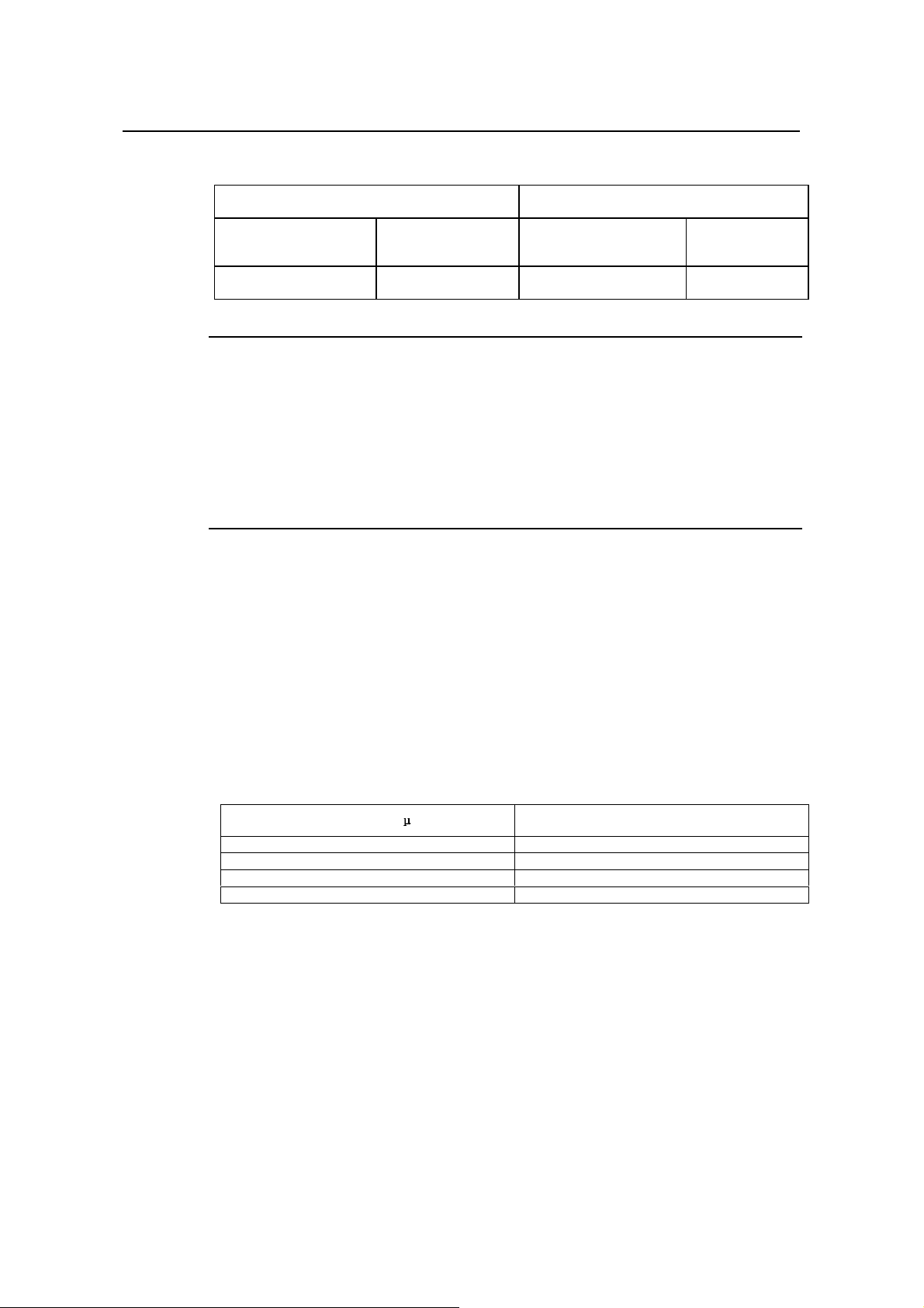
Table 3-1 Humidity requirement in the equipment room
Temperature Relative humidity
Chapter 3
Installation Preparations
Normal operating condition
15OC to 30OC0
Note:
Safety operating
condition
1) The values of environmental temperature and humidity in the equipment room are measured at 1.5m
high and 0.4m away from the front of the router rack when there is no protective board installed in front and
at the back of the rack.
2) Safety operating condition refers to the continuous operation for less than 48 hours or the accumulative
annual operation time less than 15 days.
3) The extreme environment refers to the likely environmental temperature and humidity when the air
conditioning system in the equipment room fails (the normal operating condition should be recovered
within five hours for each failure).
3.2.2 Cleanness Requirements
Dust undermines the n ormal operation of R2600/3600 ser ies. Dust dropping on the
equipment can cause electrostatic adsorption, which degrades the contact
performance of the metal connection parts or connectors. This happens more
frequently when the indoor relative humidity is low, which will not only shorten the
router’s service life, but also cause communication failure.
Normal operating condition
O
Cto 45OC 40% to 65% 10% to 90%
Safety operating
condition
The recommended specification on dust content and particle diameter in the equipment
room is shown in Table 3-2:
Table 3-2 Specification on dust content in equipment room
Maxim diameter ( m)
0.5 1.4 x 10
17 x 10
3 2.4 x 10
5 1.3 x 10
Max. intensity (particles per cubic meter)
7
5
5
5
The routers also have rigorous demand on the content of salts, acids and sulfides in the
air. These harmful gases will speed up the metal rust ing and the aging pr ocesses of
certain parts. The eq uipment room should be pr otected from the invasio n of harmful
gases such as SO
S, NO2, NH3 and Cl2, the value limits of which are shown in T able
2, H2
3-3:
3-2

Installation Manual
Quidway R2600/3600 Series Modular Routers
Table 3-3 Value limits for harmful gas contents in equipment room
Gas Average (mg/m3) Max. (mg/m3)
SO
2
H2S 0 0.03
NO
2
NH
3
Cl
2
3.2.3 ESD-Preventive Requirements
Although many antistatic considerations have been given to R2600/3600 series,
damage to the router’s circ uit or e ve n th e whole equipment may still h app en when the
static electricity exceeds the tolerance threshold.
In the communication network to which the routers are connected, static induction
mainly comes from:
External electric fields such as outdoor high voltage power line or thunder.
z
z Internal environment like flooring materials or the whole equipment structure.
Thus, the following should be considered to safeguard the equipment against the static
damage:
z Make sure that the equipment and the floor are well grounded.
z Make sure that dust-proof measures are taken.
Maintain an appropriate humidity and temperature.
z
z Wear an ESD-preventive wrist strap and uniform when contacting the circuit
board.
Place the uninstalled circuit board on the antistatic workbench, with its face
z
upward, or put it into the electromagnetic shield bag.
z When observing or rem oving the un insta lled cir cuit bo ard, pleas e touch th e ed ge
of the circuit board, and avoid contacting the devices on it.
Chapter 3
Installation Preparations
0.2 1.5
0.04 0.15
0.05 0.15
0.01 0.3
3.2.4 Anti-interference Requirements
The interference sources, no matter where they come from, affect the routers with
capacitance coupling, inductance coupling, radiation of electromagnetic wave,
common impedance (incl uding the grounding s ystem) or conducting li ne (power line,
signal line and transmission line etc.).
So the following should be considered:
z Take effective measures to prevent the power system from being interfered with
by the power grid system.
Separate the working ground of the router from the grounding device of the power
z
supply equipment or anti-lightning grounding device as far as possible.
Keep the router far away from the radio launcher, radar launcher, and high-
z
frequency devices working in high currents.
z Use electromagnetic shielding when necessary.
3.2.5 Lightning Protection Requirements
Although many measures have been taken to protect R2600/3600 series from lightning,
if the lightning intensity exceeds a certain range, damage to the router may still happen.
To protect the router from lightning better, the following should be considered:
3-3

Installation Manual
Quidway R2600/3600 Series Modular Routers
Ensure the shell of the chassis is well grounded through the ground wire.
z
z Ensure the neutral point of the socket of AC power supply is well grounded.
z To enhance the lightning protection capability of the power supply, a lightning
arrester could be installed at the input end of the power supply.
z As for the signal line led out to the outdoor from the function modules of
R2600/3600 series, such as ISDN line, telephone line, E1 line, etc, a special
lightning arrester should be installed at the input end of the signal line to enhance
the lightning protection capability.
3.2.6 Workbench Requirements
No matter whether you are to install the router in the cabi net or direct ly place i t on the
workbench, it is necessary to ensure that:
z There is spacing reserved at the air inlet and outlet in the router so as to facilitate
the radiation of the router cabinet.
z The cabinet and workbench have good radiation systems.
The cabinet and workbench are firm enough to support the weight of the router
z
and other installation accessories .
z The cabinet and workbench are well grounded.
3.3 Tools and Devices Required
Chapter 3
Installation Preparations
1) Tools required
Phillips screwdriver
z
z Flathead screwdriver
z ESD-preventive wrist strap
2) Connection cables
z Power cable
z Console cable
Auxiliary cable
z
Ethernet cable
z
z Interface cable for selected modules
3) Required Devices
Ethernet HUB or LANSWITCH
z
z CSU/DSU or other DCE
Configuration terminal (can be an ordinary PC)
z
Equipment related with selected modules
z
Caution:
R2600/3600 series are not equipped with any installation tools, and the user has to prepare the tools.
3-4
Installation Manual
Quidway R2600/3600 Series Modular Routers
Chapter 4 Installation
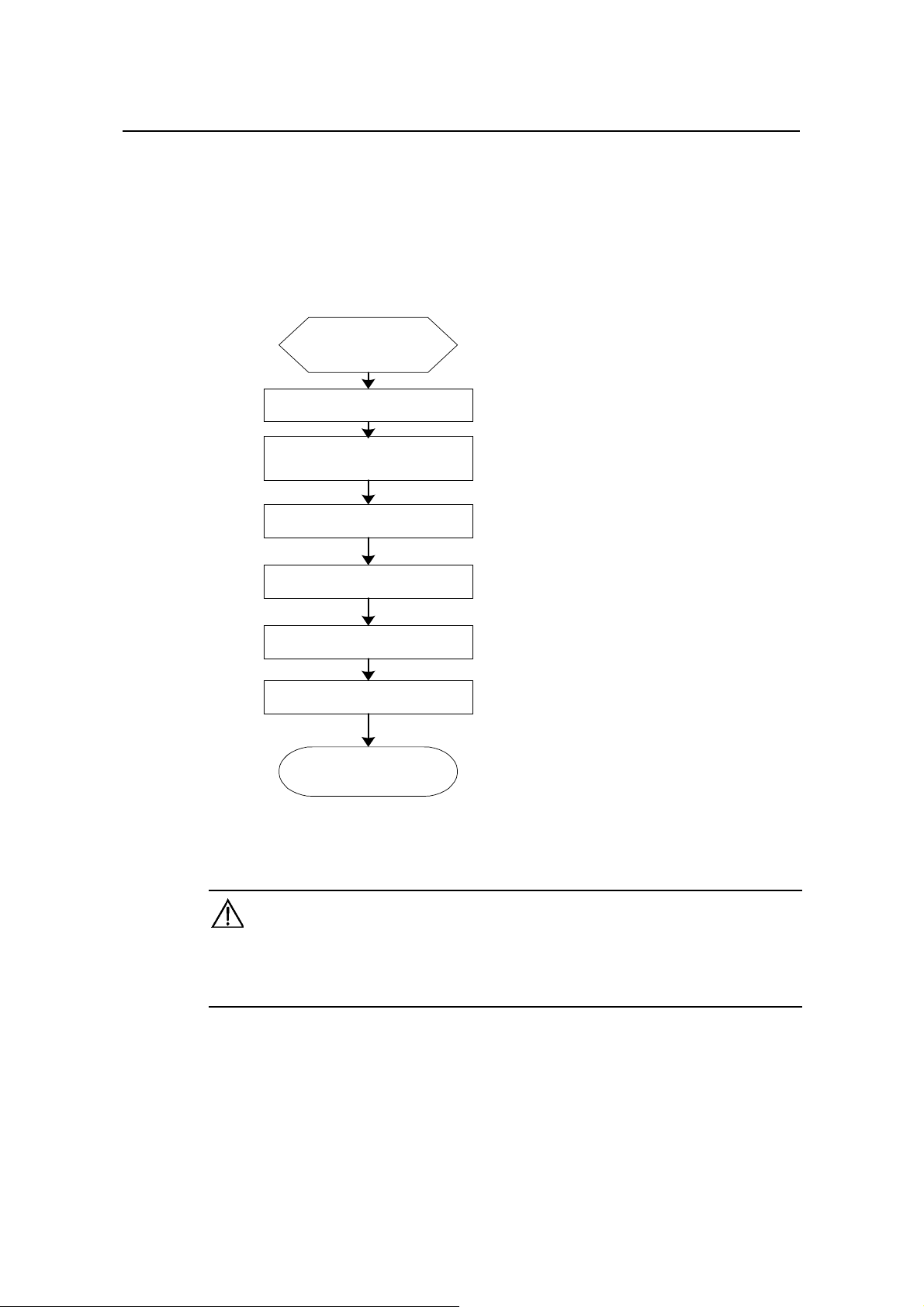
4.1 Installation Flow
Begin to install
Preparation and confirmation
Connect the router to the
specified position
Connect various cables
Chapter 4
Installation
Check after installation
Power on
Configure the router
Installation completed
Figure 4-1 Flow for installing R2600/3600 series routers
Caution:
Before starting the work described in 4.2 and 4.3, please make sure:
1) You have carefully read Chapter 3 Installation Preparations.
2) The requirements specified in Chapter 3 have been met.
4.2 Mechanical Installation
When you have completed the above work, you can start to install the router.
There are two methods for installing the router depending on the installation position:
4-1
Installation Manual
Quidway R2600/3600 Series Modular Routers
Installing it in the cabinet
z
z Placing it on the workbench
4.2.1 Installing the Router in a Cabinet
R2600/3600 series ha ve been design ed acc ording to the s i ze of the st andard 19- inch
cabinet, and their dimensions are respectively:
Quidway R3680, R3680E: Width x height x depth = 440mm x 86mm x 400mm
Quidway
Width x height x depth = 440mm x 43mm x 400mm
Quidway R2620, R2621: Width x height x depth = 440mm x 86mm x 300mm
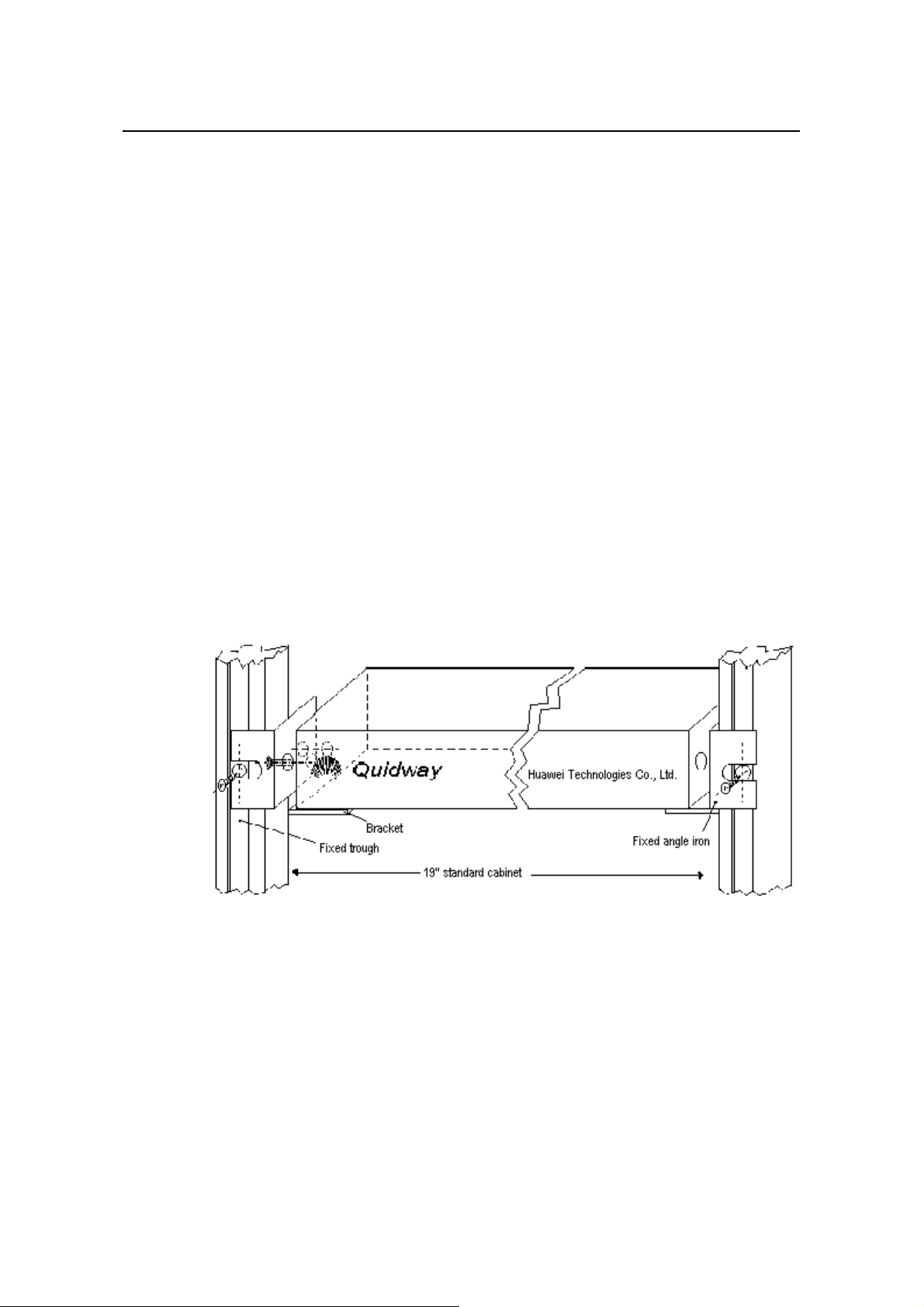
As shown in Figure 4-2, the flow for installing the router is as follows:
Step 1: Check the grounding condition and secureness of the cabinet. Secure the
bracket to both sides of the front/rear panel of the router.
Step 2: Place the router on one of the trays in the cabinet. Move the router to a proper
position along the gu ide rail in the cabinet. Le ave an appropriate spac e between the
router and guide rail.
R2630, R2630E, R2631, R2631E, R3640, and R3640E:
Chapter 4
Installation
Step 3: Screw the bracket to the fixed guide rail at both sides of the cabinet.
In this way, the router is firmly fixed to the cabinet through the tra y at each slot in the
cabinet and the bracket of the router.
Figure 4-2 Mechanical installation of the Quidway R26/ 36 series
4.2.2 Installing the Router on Workbench
In most of the cases, you do not have a standard 19-inch cabinet. Then, you can place
the routers on clean workbenches. This is a simple operation. During this operation, the
operator:
z Must ensure the stability and good grounding of the workbench.
Must reserve a 10cm for heat-dissipation around the router.
z
Do not place any heavy object on the router.
z
4-2
Installation Manual
Quidway R2600/3600 Series Modular Routers
4.3 Power Connection
4.3.1 Connecting Power Cable
R2600/3600 series supp ort the AC/DC power modules (See Chapter 2 Appearance
and System Features). You can select different types of power m odules accor ding to
the specific environment where the router is used.
The AC and DC routers of R2600/3600 series ha ve basically the sam e features and
functions. They differ in their input voltages only.
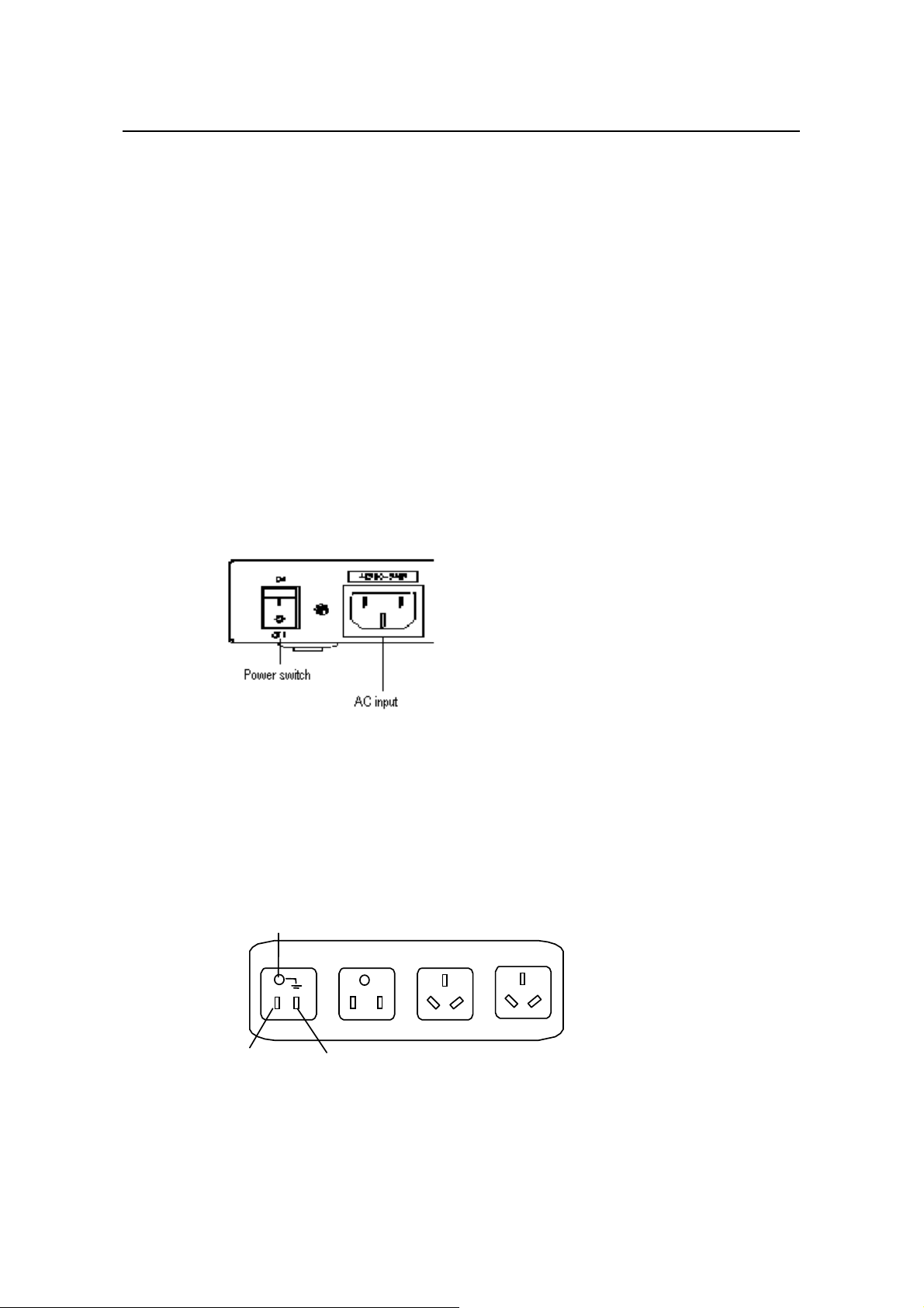
I. AC power and power cable
z AC power
For the power socket of the AC-input router, see Figure 4-3.
Input power:
180 to 240V, 50/60Hz AC (R2630, R2631, R3640, and R3680)
85 to 264V, 50/60Hz AC (R2630E, R2631E, R3640E, R3680E, R2620 and R2621)
Chapter 4
Installation
Figure 4-3 Power socket of AC-input router
z Recommended AC power socket
A monophase 3-wire power sock et with a neutr al poi nt connector, or a specia l power
socket for the c om puter is rec omm ended. The neutra l poin t of the po wer in a bui lding
must be reliably grounded. Normally, the neutral point of the power supply system in a
building will have been gr ounded during the construction and wiring. T he user must
make sure that the power supply for the building is earthed.
Neutral point
Zero line
Figure 4-4 Recommended AC power socket
Connecting AC cable
z
Live line
4-3
Installation Manual
Quidway R2600/3600 Series Modular Routers
Step 1: Connect one end of the gro und ca bl e on the chass is ac c ompanying the router
to the ground pin on the router’s rear panel, and well ground the other end.
Step 2: After confirming the power switch of the router is turned off, connect one end of
the power line accom pan ying the router to th e po wer input s ock et on th e router ’s r ear
panel, and connect the other end to the AC socket that delivered with the router.
Step 3: Switch the power switch of the router to the ON position.
Step 4: Check that the power indicator on the rear panel of the router is on. On means
the power cable is correctly connected.
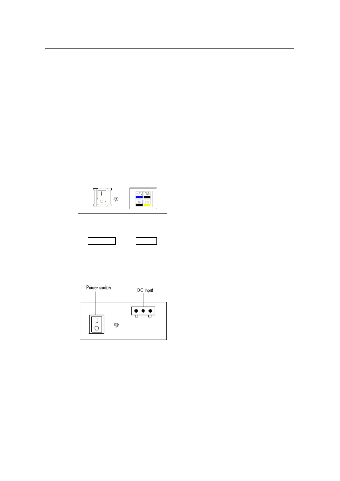
II. DC power and DC cable
z DC power
Input power: -45V to -70V DC
R3640, R3640E, R3680, R3680E, R2630E, and R2631E routers use the DC-input
socket, as shown in Figure 4-5.
Chapter 4
Installation
Power switch DC-input
Figure 4-5 Power socket of DC-input router (R3640/R3680/R2630E/R2631E/R3640E/R3680E)
R2620 and R2621 routers use the DC-input socket, as shown in Figure 4-6.
Figure 4-6 Power socket of DC-input router (R2620/R2621)
Connecting DC cable
z
Step 1: Connect one end of the gro und ca bl e on the chass is ac c ompanying the router
to the ground pin on the router’s rear panel, and well ground the other end.
Step 2: After confirming the power switch of the router is turned off, connect one end of
the power line accompanying the router to the power socket on the router’s rear panel,
and connect the other end to the –48V DC power of the switch.
Step 3: Switch the power switch of the router to the ON position.
4-4
Installation Manual
Quidway R2600/3600 Series Modular Routers
Step 4: Check that the power indicator in the rear panel of the router is on. It is on when
the power cable is correctly connected.
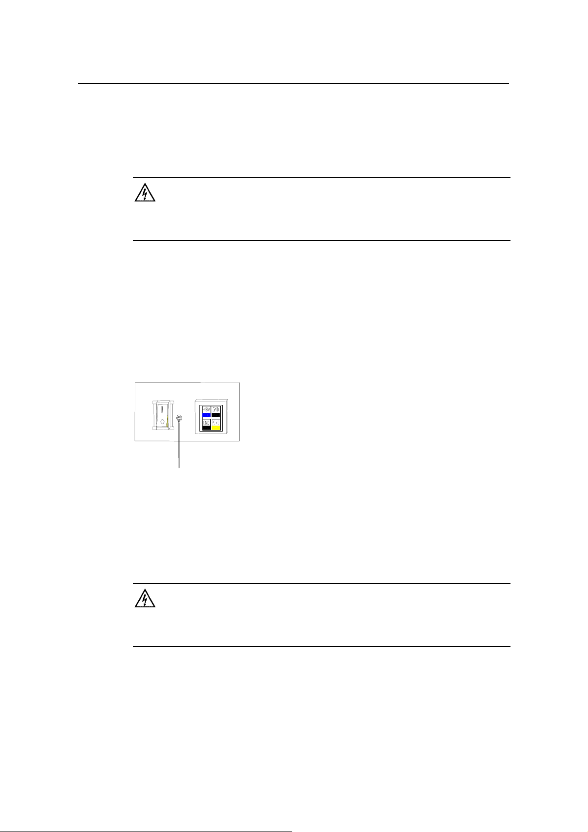
4.3.2 Connecting Ground Cable
Warning:
The normal connection of the router’s ground cable is the primary guarantee for the anti-lightning and
anti-interference capability of the router, so you must connect the ground cable carefully.
The AC input connector of R2600/3600 series comes with an AC noise filter unit,
whose central ground is directly connected with the cabinet, forming the so-called
chassis ground (also called the protection ground). This chassis must be well grounded
so that the induction power and leakage power can be released to the ground to
improve the whole router’s performance to withstand electromagnetic interference.
This ground also provides protection against the lightning and over-voltage likely to be
caused by the external network cable such as the E1 interface and ISDN cables.
Chapter 4
Installation
The ground point of the chassis is located near the AC power and switch at the back of
the cabinet, as shown in Figure 4-7. The point shall be connected to the ground.
Ground point
Figure 4-7 Ground point on the chassis
Please connect this point to the ground with a gr ound cable, and make sure that the
ground resistance is n ot greater t han 5- ohm. If the router is inst al led in a s tan dard 1 9inch cabinet, then this cabinet should be grounded in the same way.
Warning:
The router must be well grounded for the normal working; otherwise it cannot guard against lightning, and
is likely to cause damage to the router and the far-end equipment connected with this router!
4.4 Connecting Interface Ca ble on Main Control Panel
Note that Console and AUX interface c annot be us ed at the sam e tim e. You can only
choose either of them.
4-5

Installation Manual
Quidway R2600/3600 Series Modular Routers
4.4.1 Connecting Console Port
I. Introduction to console
R2600/3600 series provide a console in compliance with the EIA/TIA-232
asynchronous serial standard, through which the user can implement the local
configuration of the router.
II. Attributes of console
Table 4-1 Attributes of console
Attributes Description
Connector RJ-45
Interface standard Async EIA/TIA-232
Baud rate 9600bps
---Command line interface
Services supported
---Connection with the character terminal
---Connection with the serial interface of the local PC, and running the terminal
emulation program on the PC
Chapter 4
Installation
III. Console cable
The console cable is an 8- core shielded cable. One end of it is a pressure crimped
RJ-45 connector, and the other end is a co nnector with a DB- 9-pin and a D B-25-pin.
You can select either of them based on your act ual requirement and plug it with the
25-pin or 9-pin at the configuration terminal. The console cable is shown in Figure 4-8:
Enlarged A side
Pos. 25
DB 25 Female
A
Pos.1
8P8C PLUG
DB9 Female
Enlarged B side
B
Pos.1 Pos.8
Enlarged C side
Pos.1
C
Pos.9
Figure 4-8 Console cable
4-6

Installation Manual
Quidway R2600/3600 Series Modular Routers
Table 4-2 Console cable pinouts
RJ-45 Signal Direction DB-25 DB-9
1 CTS ---> 5 8
2 DSR ---> 6 6
3 RXD ---> 3 2
4 GND --- 7 5
5 GND --- 7 5
6 TXD <--- 2 3
7 DTR <--- 20 4
8 RTS <--- 4 7
IV. Connecting c onsole cable
While configuring the router at the configuration terminal, connect the console cable in
the following steps:
Step 1: Plug the console cable’s DB-9 (or DB-25) connector to the serial interface in the
PC or the terminal where the router is to be configured.
Step 2: Connect the RJ-45 connector of the console cable to the console of the router.
Chapter 4
Installation
Caution:
When connecting the cables, check the ID on the interfaces to avoid wrong connection.
For the connection of the console cable, see Figure 5-1 in Chapter 5 Startup and Configuration.
4.4.2 Connecting AUX Port
I. Introductio n t o AUX
R2600/3600 series provide an AUX in compliance with the EIA/TIA-232 asynchronous
serial standard. Thr ough this interface, you can implem ent the remote configuration
and maintenance of the router.
II. Attributes of AUX
Table 4-3 Attributes of AUX
Attributes Description
Connector RJ-45
Interface standard Async EIA/TIA-232
Baud rate 300bps to 115.2Kbps
Services supported Dialup via Modem
4-7

Installation Manual
Quidway R2600/3600 Series Modular Routers
III. AUX cable
The AUX cable is an 8-core shielded cable. One end of it has a RJ-45 connector
adopting RS-232 stand ard, whic h is to be c onnec ted to AUX. T he D B-25-pin and DB9-pin connector of the other end ar e p lugge d with the DB-25-pin or DB-9-pin s ocket in
Modem according to the actual requirements. The AUX cable is shown in Figure 4-9:
Enlarged A side
Pos.1
Chapter 4
Installation
A
Pos. 25
Figure 4-9 AUX cable
Table 4-4 AUX cable pinouts
RJ-45 Signal Direction DB-25 DB-9
1 RTS ---> 4 7
2 DTR ---> 20 4
3 TXD ---> 2 3
4 DCD <--- 8 1
5 GND --- 7 5
6 RXD <--- 3 2
7 DSR <--- 6 6
8 CTS <--- 5 8
DB25 Male
8P8C P LU G
Label
DB9 Male
Enlarged B side
B
Pos.1 Pos.8
Enlarged C side
Pos.9
C
Pos.1
IV. Connecting AUX cable
Complete the connection of AUX cable in reference to Figure 4-10:
Step 1: Plug the RJ-45 end of the AUX cable to the AUX interface of the router.
Step 2: Connect th e DB-25 end of the AUX c able to the ser ial interf ace of the ana log
Modem.
4-8

Installation Manual
Quidway R2600/3600 Series Modular Routers
Set up a rem o te co nfigu ration
environment
Telephone cable
Chapter 4
Installation
MODEM Serial interface cable
MODEM
PSTN
MODEM
Quidway R3640
AUX cable
Figure 4-10 Setting up remote configuration environment via the AUX interface
Caution:
Console and AUX cannot be used at the same time.
4.5 Connecting Interface Cable
Please refer to Chapter 8 Function Modules.
4.6 Installation Check
660000
On completion of the m echanical ins tallation of the router, please check the f ollowing
before powering on the router:
If the router is installed in the cabinet, please check that the cabinet and the
z
bracket of the router are s ecure. If it is instal led on the work bench, pleas e check
that enough spacing is reserved about the router for heat-dissipation, and that the
workbench is secure.
Check that the power supply conn ec ted t o the p o wer c able is c ons istent with that
z
required by the router.
z Check that the ground cable of router is correctly connected.
Check that the router and configuration terminal and the other devices are
z
correctly connected.
4-9

Installation Manual
Quidway R2600/3600 Series Modular Routers
Caution:
It is very important to check after the router has been installed. For the normal operation of the router is
directly affected by following factors: whether the router is mounted firmly, whether it is well grounded, and
whether it uses proper power supply.
Chapter 4
Installation
4-10

Installation Manual
Quidway R2600/3600 Series Modular Routers
Chapter 5 Startup and Configuration
5.1 Starting the Router
If R2600/3600 series are ins talled and used for the firs t time, you can only conf igure
through the console port.
5.1.1 Setting up Configuration Environment
Set up a local configuration
environment
Chapter 5
Startup and Configuration
RS232 Serial interfrace
Console(Console)Cable
Figure 5-1 Setting up a local configuration environment through the console
Quidway R3640
Console(Console)
I. Connecting console port cable
Step 1: Plug the DB-9/25 connector of the console cable to the serial interface in the PC
or at the terminal where the router is to be configured.
Step 2: Connect the RJ-45 connector of the console cable to the console.
II. Setting terminal parameters
Step 1: Start the PC or terminal.
If a PC is used for the configuration, it is necessary to run a terminal emulation program
on the PC, like Windows3.1 Terminal, and the HyperTerminal of Windows95/98/NT.
Step 2: Set terminal parameters.
Parameter setting requirements:
Set the baud rate to 9600, the d ata bits to 8, no parit y check, stop bit to 1, no traffic
control, and terminal emulation to VT100.
5-1

Installation Manual
Quidway R2600/3600 Series Modular Routers
Set the Windows 98 HyperTerminal parameters as follows:
1) In the HyperTerminal window shown in Figure 5-2, click on the
and a HyperTerminal dialog box will pop up as shown in Figure 5-3.
2) Select the serial inter face for connection in
property dialog box. The selected serial interface should be consistent with that of
the console cable. Clic k on
configuration window shown in Figure 5-4.
3) In the serial interface property dialog box, set the baud rate to 9600, data bit to 8,
no parity check, stop bit to 1, and no traffic control. Click on
HyperTerminal property dialog box as shown in Figure 5-3.
4) Select
setting window as sho wn in Figur e 5-5. Selec t the term inal emulation as VT100 ,
and click on
[Setting]
in the HyperTerminal property dialog box and access the property
.
<OK>
<Configure>
Chapter 5
Startup and Configuration
<Property>
[Connect To]
to access the serial inter face property
in the HyperTerminal
to return to the
<OK>
button,
Figure 5-2 HyperTerminal window
5-2

Installation Manual
Quidway R2600/3600 Series Modular Routers
Chapter 5
Startup and Configuration
Figure 5-3 HyperTerminal property dialog box
Figure 5-4 Setting serial interface parameters
5-3

Installation Manual
Quidway R2600/3600 Series Modular Routers
Chapter 5
Startup and Configuration
Figure 5-5 Setting terminal type
III. Power on the router
After making sure that the router and the configuration terminal are correctly connected
and having completed the setting of configuration terminal parameters, you can power
on the router.
5.1.2 Powering on Router
I. Preparation
Before powering on the router, check:
z That the power and ground cables are correctly connected.
z That the voltage meets the requirements required by the router.
That the console cable is correctly connected; the PC or the terminal for
z
configuration has been started; and the setting is completed.
Warning:
Before powering on the router, please make sure of the position of its power switch so as to cut off power
supply in time when an accident occurs.
5-4

Installation Manual
Quidway R2600/3600 Series Modular Routers
II. Powering on the router
Powering on the router as follows:
Switch on the power supply for the router.
z
Turn on the switch of the router (set the switch of the router to ON).
z
III. Power-on Check
After the router is powered on, please check:
That the ventilation system works normally
z
Method: When the router is powered on, you should be able to hear the running of the
fan. When placing your hand near the vent of the router, you should be able to feel the
flow of the air.
That the indicator on the front panel of the router is normal
z
Method: when the router is powered on, the POWER indicator on the front panel is on.
That the configuration terminal displays information normally.
z
Method: when the router is powered on, the terminal will show such system information
as the version of the router.
5.1.3 Starting Router
Chapter 5
Startup and Configuration
I. Starting BOOT
When the router is powered, it will run the BOOTROM program first. The screen on the
terminal will show the following system information:
Be aware that the BOOTROM terminals of different versions may have slightly different
interfaces.
Quidway starts booting
******************************************
* *
Quidway Series Router Boot Rom, V4. 10
* *
******************************************
Copyright(C) 19 99-2001 by Hua we i Technologies Co., Ltd.
Now Testing Memory...OK!
64M bytes DRAM
8192K bytes flash memory
Press Ctrl-B to enter Boot Menu .... ......
Press
<Ctrl+B>
, and the system will acces s the BOOT menu. Other wise the system
will initialize.
Note:
Within a few seconds after the appearance of “Press Ctrl-B to enter Boot Menu...” it is necessary to press
<Ctrl+B> to access the BOOT menu; otherwise, the system will begin the program decompression
process. To access the BOOT menu after the program decompression process begins; you have to restart
the router.
5-5

Installation Manual
Quidway R2600/3600 Series Modular Routers
II. Initializing the system
If the router is powered on, the router will start self-check. When self-check is
completed, the terminal screen will display:
Press ENTER key to get start when you se e ATS0=1
System now is starting ...ATS0=1
Press
<Enter>
Quidway>
and the screen will show:
This prompt indicates that the ro uter has entered the norm al configuration mode (as
described in “5.2 Configuration Basic”).
Note:
If ATS0=1 appears, it indicates that system initialization has completed and the router works normally.
5.1.4 Configuring Router via Setup
Chapter 5
Startup and Configuration
In Setup mode, you are guided in an interacti ve m anner (dialog) to set t he neces sary
basic parameters for the router.
Setup is usually used for BO OTSTRAP configuration f or the rou ter when it is po were d
on for the first tim e, or it can be use d at an y tim e in pri vileg ed co nf iguration m ode (as
described in “5.2 Configuration Basic”).
Configurations made in Setup include:
Global parameter:
z Hostname of the router
z Privileged user password
z SNMP
IP
z
Parameters configured for the interfaces:
IP address
z
z IPX address
The specific configuration steps are as follows:
I. Confirming whether to make t he configuratio n
In privileged mode, enter
<Setup>
and the following inf ormation will be dis played on
the terminal screen:
Quidway#setup
--- System Config uration Dial og ---
Default settings are in square brackets '[]', if you do not change the default
settings, you may input enter. And Ctrl-C can cancel at any time without saving.
Continue with configuration di alog? [yes]:y
“[]” contains the default s ystem s ettings. If you do not want to change it, d irectl y press
<Enter>
. Press
<Ctrl+C>
The last line prom pts the us er to c ont inu e with the configuration. En ter
to exit setup mode at any time.
to exit the
<N>
Setup mode.
5-6

Installation Manual
Quidway R2600/3600 Series Modular Routers
II. Displaying the interface status
Firstly, would yo u like to see the cu rr ent interface su mmary? [yes]:y
Interface IP-Address OK? Status Protocol
Ethernet0 129.102.100.141 yes down up
Serial0 yes up down
Serial1 yes up down
Serial2 yes up down
III. Configuring global parameters
Configuring global parameter s:
Enter host name [Quidway]:
Enter enable password []:
Configure SNMP Network Management? [YES]:
Community strin g []: public
Configure IP? [yes]:
Configure IPX? [NO]: y
IV. Configuring interface
Configuring interface Ethern et0:
Is this interface in use? [YES]:
Configure IP and ma sk on this inter fa ce? [YES]:
IP address for this interface [129.102.100.141]:
Netmask [255.255.0.0]:
Class B network is 129.102.0.0.
IP address is 129.102.100.141, netmask is 255.255.0.0.
Configure IPX on this interface? [NO]:y
IPX network number for this interf ace [1]:
Configuring interface Serial 0:
Is this interface in use? [YES]:
Configure IP on this interface? [N O]:
Configure IPX on this interface? [NO]: y
Chapter 5
Startup and Configuration
Configuring interface Serial 1:
Is this interface in use? [YES]:
Configure IP on this interface? [N O]:
Configure IPX on this interface? [NO]:
Configuring interface Serial 2:
Is this interface in use? [YES]:
Configure IP on this interface? [N O]:
Configure IPX on this interface? [NO]:
V. Displaying configuration results
The following configuration wa s created:
hostname Quidwa y
enable password
snmp-server community ro
ipx routing
interface Ethernet0
no shutdown
ip address 129.10 2.100.141 25 5. 255.0.0
ipx network 1
interface Serial0
no shutdown
no ip address
no ipx network
interface Serial1
no shutdown
no ip address
no ipx network
interface Serial2
5-7

Installation Manual
Quidway R2600/3600 Series Modular Routers
no shutdown
no ip address
no ipx network
End
VI. Confirming t he configuratio n
Use this configuration? [yes/n o]:
Now writing the configuration to flash memory.
Write the running config to flash me mory successfull y.
Please reboot the router.
5.2 Configuration Basic
5.2.1 Basic Configuration Mode
The command lines for R2600/3600 series are hierarchically protected to prevent
unauthorized users f rom access ing it. It provides a rich divers ity of comm and modes
and the three most basic modes are:
Normal mode
z
z Privileged mode
z Global mode
Chapter 5
Startup and Configuration
Note:
For the details about configuration commands and command line interfaces, refer to VRP User Manual Configuration Guide (V1.5).
Table 5-1 Feature list for basic command modes
Command
mode
Normal
mode
Privileged
mode
Global
mode
View the simple running
states and statistics of the
router
View the entire running states
and statistics of the router.
File management and system
management can be
performed at the same time
Configure global parameters Quidway(config)#
Feature Prompt Entry command Exit command
Quidway>
Quidway#
Access the mode
after connection
with the router is
created.
Enter <enable> in
normal mode and
access the mode
after entering the
correct enable
password (no
password is set for
the router by
default).
In privileged
mode, enter
<config>
Enter <exit> to
disconnect the
connection from the
router
Enter <disable> to
return to the normal
mode.
Enter <exit> to
disconnect the
connection from the
router and return to
the normal mode
Enter <exit> to return
to privileged mode
Note:
In general, for a certain mode, only the command defined by this mode can be executed.
5-8

Installation Manual
Quidway R2600/3600 Series Modular Routers
5.2.2 Help
R2600/3600 series provide a rich set of online help:
1) In any command mode, enter
2) In any comm and m ode, enter
description about the command.
3) Enter a command, followed by
words, all the key words and the related brief description will be given.
4) Enter a command, follo wed by
arguments, the descriptions of the related arguments will be listed.
5) Enter a character string followed by
string will be shown.
6) Enter a comm and, followed b y a character s tring a nd
beginning with this string will be liste d.
Chapter 5
Startup and Configuration
<help>
<?>
for a brief description for the related help.
for all the com mands in this mode an d a br ief
separated by a space. If this position is for key
<?>
separated by a space. If this position is for
<?>
, and all the commands beginning with this
<?>
, and all the key words
<?>
5-9

Installation Manual
Quidway R2600/3600 Series Modular Routers
Chapter 6 Maintenance
6.1 Software Maintenance
The software maintenance of router includes software upgrade and file uploading/
downloading.
The manageable files of the router include:
z BOOTROM program file
z Main program file
z Configuration file
This chapter will introduce f ile uploading and download ing via FTP. The following t wo
methods are for software upgrade:
z Software upgrade via XModem
Software upgrade via TFTP
z
Chapter 6
Maintenance
Note:
To upgrade the main program via TFTP and FTP, you need to use the E thernet interface. Refer to Chapter
8 Function Modules for how to connect the Ethernet cables.
6.1.1 BOOT Menu
BOOT menu will be used during the maintenance of the router software.
Attach a terminal (or a PC. For PC, it is necessary to run a terminal emulation program)
to the console of the router. After the router is powered on, the following information will
display:
Note:
Different versions of BOOTROM may have slightly different interfaces at the terminal.
Quidway start booting
******************************************
* *
* Quidway Series Rou ter Boot Rom, V4 .1 0 *
* *
******************************************
Copyright(C) 19 99-2001 by Hua we i Technologies CO., LTD.
Now Testing Memory...OK!
64M bytes DRAM
8192K bytes flash memory
Press Ctrl-B to enter Boot Menu .... ......
Press
<Ctrl+B>
, and the system will access the BOOT menu.
6-1

Installation Manual
Quidway R2600/3600 Series Modular Routers
Note:
In order to access the BOOT menu, you shall press <Ctrl+B> within a few seconds after the information
“Press Ctrl-B to enter Boot Menu...” appears; otherwise the system will enter the program decompression
process. At this time if you want to access the BOOT menu, you will have to restart the router.
The system will prompt:
Please input bootrom password:
You are required to enter the password. After entering correct password (no password
is set for the router by default), the system will access the BOOT menu:
Caution:
While using the router, please always remember the modified BOOTROM password.
Boot Menu:
1: Download applic ation progra m wi th XMODEM
2: Download applic ation progra m wi th TFTP
3: Clear application password
4: Clear configuration
5: Exit and reboot
Enter your choice (1-5):
Chapter 6
Maintenance
6.1.2 Upgrading Software via XModem
I. Upgrading ma i n program
Step 1: Enter
via XModem. The router supports the following download speeds:
Please choose your download speed:
1: 9600 bps
2: 19200 bps
3: 38400 bps
4: 57600 bps
5: 115200 bps
6: Exit and Reboot
Enter your choice (1-6): 5
Step 2: Select the appropriate download speed based on the actual requirements. For
example, enter
Download speed is 11520 0 bps. Change the term inal's speed to 115200 bps, and
select XMODEM protocol. Press EN TER key when ready.
Step 3: Follow the abo ve prompt and change the baud rat e set at the configuration
terminal, so that t he b aud r ate is the s ame as that of the s of twar e do wnl oad . Af ter th e
baud rate of the configuration ter minal is completed, disconnect and then re- connect
the terminal. Pres s
information:
Now Downloading Program File. Please Start Transfer Program File Use Xmodem
Protocol. If You Want To Exit Press <C trl+X>. Download ing ... CCCCC
in the BOOT menu, and select to download the application program
<1>
for 115200bps, the router will provide the following information:
<5>
<Enter>
to start downloading, the ro uter will prov ide the follo wing
6-2

Installation Manual
Quidway R2600/3600 Series Modular Routers
Note:
After the terminal baud rate is modified, it is necessary to disconnect and then re-connect the terminal, so
as to effect the new setting.
Chapter 6
Maintenance
Step 4: Select
[Transfer\Transfer File]
from the term inal window, and the following
dialog box will be popped up.
Figure 6-1 [Send File] dialog box
Step 5: Click on
<Browse>
, select the program to be downloaded. Change the
download protocol to XMo dem. Then click on
interface as shown in Figure 6-2.
[Send]
and the system will pop up the
Figure 6-2 “Xmodem file send” interface
Step 6: After the download com pletes, the s ystem begins t o writ e to the Flash. When
this operation completes, the terminal interface displays the following information,
indicating the completion of downloading.
Download comple ted.
Writing to flash me mory...
6-3

Installation Manual
Quidway R2600/3600 Series Modular Routers
Please waiting, it needs a long tim e (a bout 1 min).
Write Flash Success.
Please return to 96 00 bps. Press EN TE R key to reboot the sy stem.
II. Upgrading BOOTROM
Step 1: Attach a terminal or a PC (For a PC, it is necessary to run a terminal emulation
program) to the conso le of the router. Power on the router for self-check. When the
interface of the term inal running em ulation program displays “Qu idway start booting”,
press
<Ctrl+D>
and the system will prompt you to enter th e BOOTROM password, as
shown below:
Please input boot rom password:
Step 2: Enter correct pas sword. (By default, there is no BOOTROM password. If the
router has been configur ed with password, please e nter the correct pas sword.) Then
the system displays the following menu:
Boot Menu:
1: Download Bootrom program
2: Modify Bootrom pa ssword
3: Reboot
Enter your choice (1-3): 1
Step 3: Enter
, select to download BOOTROM program, and the subsequent steps
<1>
are the same as that in “6.1.2 Upgrading main program”.
Chapter 6
Maintenance
6.1.3 Upgrading Main Program via TFTP
Note:
While upgrading the main program via TFTP, you need to use the Ethernet interface. For cable connection
method, refer to Chapter 8 Function Modules.
Step 1: Select the Ethernet interface for downloading.
R2600/3600 series support loading application program via a specified Ethernet
interface:
z R2630, R2631, R2620 and R2621: Ethernet 0.
R3640 and R3640E: search for 1FE b oard in t he or der of slots 0, 2, 1, and 3 un ti l
z
an Ethernet interface is found, and this interface will serve as the download
Ethernet interface. If there is no 1FE, then search for 2FE board in the same order,
and Interface 0 of the first 2FE found will serve as the Ethernet interface for
downloading.
z R3680 and R3 680E: searc h for 1FE board in t he order of slots 0, 2, 4, 6, 1, 3, 5,
and 7 until an Ethernet interface is found, and this interface will serve as the
download Ethernet interf ace. If ther e is no 1F E, then s earch f or 2F E board in the
same order, and Interface 0 of the first 2FE found will serve as the Ethernet
interface for downloading.
After specifying the E thernet interface, con nect the interface to a PC (suppose its IP
address is 10.110.10.13) via Ethernet cable. Attach a PC (can be the same PC) to the
console of the router.
Step 2: Run the T FTP Server program on the PC connected with the Ethernet, and
specify the directory for the program.
6-4

Installation Manual
Quidway R2600/3600 Series Modular Routers
Caution:
TFTP Server program is not supplied together with R2600/3600 series and should be prepared by the
user.
Step 3: Run the terminal em ulation program on the PC co nnect ed to the conso le, and
boot the router. When the screen displays “Quidway start booting”, press
immediately, and the following will be displayed:
(M)odify any of this or (C)ontinue? [M]
Press
<Enter>
For each of the following questions, you can press <Return> to select the value
shown in braces, or you can enter a new va lue.
, and the following prompt will be given:
The above prompt indicates that the following options have default values (those
contained in [ ] are default values). If there is no need to modify the value, press
<Enter>
NETWORK INTERFACE PARAMETERS :
Do you want a LAN1 interface? [Y]
This board's LAN1 IP address (0.0.0.0 = RARP)? [10.110.10.10]
Subnet mask for LAN1 (0 for none)? [25 5.255.0.0]
HARDWARE PARAME TERS:
Baud rate for serial channels [960 0]
NETUTILS APPLICATION PARAMETERS:
IP address of the TFTP Boot server to boot from? [10.110.200.1]
What is the name of the file to be loaded an d started? [ram.ab s]
How long (in seconds) should CPU delay before starting up? [2]
; or, enter a new value.
“IP address of the T FTP Boot server to boot from? [10.110.200.1]” must be the IP
address of the PC connected with the Ethernet. Here, it is 10.110. 10.13.
Chapter 6
Maintenance
<N>
After entering the last value, the following prompt will be given, requesting you to
confirm the input values:
------------------------------------------------------------------NETWORK INTERFACE PARAMETERS :
IP address on LAN1 is 10.110.10.10
LAN1 interface's subnet mask is 0xffff0000
HARDWARE PARAME TERS:
Serial channels will use a baud rat e of 9600
NETUTILS APPLICATION PARAMETERS:
IP address of the TFTP host is 10.110.10.13
The file to download and start is ram.abs
After board is reset, start-up cod e will wait 2 seconds
------------------------------------------------------------------(M)odify any of this or (C)ontinue? [M]
Step 4: Enter
to confirm the above selection, and BOO TROM will be norm ally
<C>
started. Then, access the BOOT menu with the method described in 6.1.1.
Step 5: Enter
in the BOOT menu, and download the application program via TFTP,
<2>
and the following prompt will be displayed:
Please start TFTP server then pres s ENTER key to get start
If the PC running the TFTP Server is ready, press
Starting the TFTP download...
....................... ................ .......................... .
TFTP download com pleted...
read len=[03713 478]
Writing program code to FLASH...
Please waiting, it needs a long ti me (about 1 min)
WriteFlash Succ ess.
Press ENTER key to reboot the system .
<Enter>
to start the loading.
6-5

Installation Manual
Quidway R2600/3600 Series Modular Routers
Chapter 6
Maintenance
The loading is successful. Press
Caution:
Please do not upgrade the software system of the router rashly. If necessary, upgrade under the guidance
of technical support engineer.
<Enter>
, and the router will be rebooted.
6.1.4 Uploading and Downloading Files via FTP
R2600/3600 series can serve as the FTP server and enable you to update
configuration and program files. Any FTP client can be connected to the router, and be
used to upload and d ownload the configuration a nd program files af ter passing user
authentication.
Note:
Uploading: Transferring files to the router from the PC running FTP, which is connected to the Ethernet
interface of the router.
Downloading: Transferring files from the router to the PC running FTP, which is connected to the Ethernet
interface of the router.
I. Starting the FTP server on the router
1) Set the authentication
z In global mode, enter
z In global mode, enter
z In global mode, enter
Note:
For details of the above commands, please refer to Chapter 1 AAA Configuration and RADIUS
Configuration in 07 Security Configuration of VRP User Manual - Configuration Guide (V1.5).
2) Add username and password
In global mode, enter <user ftp password 0 123 service-type ftp> is entered, it indicates
that the username is ftp and the password is 123.
3) Start the FTP server
In global mode, enter <ftp-server enable>.
With the above oper at ions , the FTP server is star te d a nd t he us er name is set. So any
FTP client program can log in the FTP server with this username and password.
<aaa-enable>
<aaa authentication login default local>
<aaa accounting optional>
.
.
.
6-6

Installation Manual
Quidway R2600/3600 Series Modular Routers
II. Uploading configuration file
Configure the Ethernet in terf ace addres s of the router to c onnect t he hos t run ning th e
FTP client program to the router.
Log in the FTP server with the username and password already set in the router. Take
the FTP client program provided by Windows 98 as an example:
z With the DOS prompt, enter <
Ethernet interface of the router).
z Under the “username” prompt, enter the username <ftp>.
z Under the “password” prompt, enter the password <123>. After the authentication,
the user login succeeds, showing the FTP client prompt “
z Enter <put> under the prompt.
z Under the “local file” prompt, enter the name of the configuration file to be
uploaded.
Under the “remote file” prompt, enter the name of the uploaded configuration file to
z
be saved at the router end. This name must be configured at the router end before
the uploading, with a default name as CONFIG.
z After file uploading is completed, the “
<dir>, showing the name and size of the file on the router. If the uploading is
successful, the size of configuration file should be the same as that on the host.
z When the uploading is successful, enter <quit> to exit the FTP client program.
Chapter 6
Maintenance
A.B.C.D> (A.B.C.D is the IP address on the
FTP
>”.
FTP
>” prompt is displayed again. Enter
FTP
III. Uploading program file
Configure the Ethernet interface address of the router so as to connect the host running
the FTP client program to the router.
Log in the FTP serv er with the usern ame and the pas sword alre ady set in the router.
Now let us take the FTP client program provided by Windows 98 as an example:
z Under the DOS prompt, enter <
Ethernet interface on the router).
z Under the “username” prompt, enter the username <ftp>.
z Under the “password” prompt, enter the password <123>. After the authentication,
the user login is successful, showing the FTP client prompt “
z Under the “
z Under the “local file” prompt, enter the name of the program file to be uploaded.
Under the “remote file” prompt, enter the name of the uploaded program file to be
z
saved at the router end. This name must be configured at the router end before the
uploading, with a default name as SYSTEM.
After file uploading is c ompleted, the “
z
<dir>, showing the name and size of the file on the router. If the uploading is
successful, the size of configuration file should be the same as that on the host.
z When the uploading is successful, enter <quit> to exit the FTP client program.
>” prompt, enter <put> under the prompt.
FTP
A.B.C.D> (A.B.C.D is the IP addres s of the
FTP
>”.
FTP
>” prompt is dis played again. Enter
FTP
IV. Downloading configuration file
Configure the Ethernet interface address of the router so as to connect the host running
the FTP client program to the router.
Log in the FTP server with the us er n ame and password alread y set in t he ro uter. Now
let us take the FTP client program provided by Windows 98 as an example:
Under the DOS prompt, enter <
z
Ethernet interface on the router).
Under the “username” prompt, enter the username <ftp>.
z
z Under the “password” prompt, enter the password <123>. After the authentication,
the user login is successful, showing the FTP client prompt “
6-7
A.B.C.D> (A.B.C.D is the IP addr ess of the
FTP
>”.
FTP

Installation Manual
Quidway R2600/3600 Series Modular Routers
Under the “FTP>” prompt, enter <get>
z
z Under the “local file” prompt, enter the name of the configuration file to be
downloaded.
z Under the “rem ote file” prom pt, enter the name of the downloaded co nfiguration
file to be saved at the router end. This name must be configured at the router end
before the uploading, with a default name as CONFIG.
z When file downloading is completed, the “
to exit the client program.
quit
V. Downloading program file
Configure the Ethernet interface address of the router so as to connect the host running
the FTP client program to the router.
Log in the FTP server with the us er n ame and password alread y set in t he ro uter. Now
let us take the FTP client program provided by Windows 98 as an example:
Under the DOS prompt, enter <
z
Ethernet interface on the router).
z Under the “username” prompt, enter the username <ftp>.
z Under the “password” prompt, enter the password <123>. After the authentication,
the user login is successful, showing the FTP client prompt “
z Under the “
Under the “local file” prompt, enter the name of the program file to be downloaded.
z
z Under the “remote file” prompt, enter the name of the downloaded program file to
be saved at the router end. This name must be configured at the router end before
the uploading, with a default name as SYSTEM.
When file downloading is completed, the “
z
<quit> to exit the client program.
>” prompt, enter <get> under the prompt.
FTP
Chapter 6
Maintenance
.
>” prompt is displayed again. Enter
FTP
A.B.C.D> (A.B.C. D is the IP a ddress of the
FTP
>”.
FTP
>” prompt is displayed again. Enter
FTP
6.1.5 Password Lost
If you have lost th e BOOTROM password or privileged user password for acc essing
the router, please contact the technical support personnel of Huawei.
6.2 Hardware Maintenance
Caution:
Before this operation, switch off the power to channel ESD voltages; otherwise, the operator may be prone
to electric shock.
R2600/3600 series have the following storage media:
DRAM or SDRAM (dynamic DRAM): used to run the programs of the router.
z
Flash: used to store program and configuration files of the router
z
z NVRAM: also used to store configuration files of the router (except R2620/2621).
BOOTROM: used to store starter and initializer of the router.
z
Hardware maintenance of R2600/3600 series mainly involve the replacement of DRAM
or SDRAM, and BOOTROM, ins tall and uninstall of the interfac e unit of the router’s
function modules.
6-8

Installation Manual
Quidway R2600/3600 Series Modular Routers
The memory bank can be replaced in the same way as BOOTROM is, by following the
flow shown below:
Start router hardware maintenance
Preparation and verification
Open the chassis
Verify the positi on of
SIMM or BOOTROM
Remove the SIMM
or BOOTROM
Install ne w SIMM
or BOOTROM
Close the chassis
Chapter 6
Maintenance
Complete hardware
maintenance
Figure 6-3 Maintenance flow for DRAM/BOOTROM
Caution:
1) Please do not replace the hardware of the router at will. If necessary, replace the hardware under the
guidance of the technical support engineer.
2) There is a seal of Huawei on a screw in the cover of R2600/3600 series. The seal shall not be opened
before the maintenance of the router. So first contact the local agent of Huawei for permission before
opening the cover of the router, or perform operations according to the relevant regulation of the local
agent. Otherwise, you shall be responsible for any unmaintainability arising from operations not permitted.
6.2.1 Opening the Chassis
I. Tools required
z Phillips screwdriver
z Flathead screwdriver
z ESD-preventive wrist strap
Caution:
These installation tools are not supplied by Huawei and shall be prepared by the user.
6-9

Installation Manual
Quidway R2600/3600 Series Modular Routers
II. Open the chassis
Caution:
Before this operation, switch off the power to channel ESD voltages; otherwise, the operator may be prone
to electric shock.
Follow the steps below to open the chassis:
Step 1: Turn off the power of the router.
Step 2: Disconnect any network cable on the rear panel of the router.
Step 3: Rest the router on a flat surf ace, with its rear panel for ward. Use the Phillips
screwdriver to remove the four screws, as shown in Figure 6-4.
Step 4: Raise the top of the chassis to such a height that the front edge of the chassis is
separated from the bottom of the router.
Step 5: Pull the chassis until the small bump occluded with the router on the back edge
is separated from the front panel.
Chapter 6
Maintenance
Step 6: Pull the chass is until it is completel y separate d from the bottom . Then s et the
chassis aside.
Screw
Mount hole
Figure 6-4 Open the chassis
6.2.2 Replacing the SIMM
SIMM (Single In-line Memory Modul e) is a com ponent of the system c ard that can be
upgraded or replaced as per your requirement. You may need to expand memor y in
either of the following situations:
6-10

Installation Manual
Quidway R2600/3600 Series Modular Routers
In case of upgrading VRP (Versatile Routing Platform, a software platform
z
independently developed by Huawei), it’s necessary to expand memory.
z If a large number of routing tables are maintained in the router, or there are some
tasks demanding huge memory, it’s necessary to expand memory.
When booting the router, you will see the following prompt:
Quidway start booting
******************************************
* *
* Quidway Series Rou ter Boot Rom, V4 .1 0 *
* *
******************************************
Copyright(C) 19 99-2001 by Hua we i Technologies CO., LTD.
Now Testing Memory...OK!
64M bytes DRAM
8192K bytes flash memory
Press Ctrl-B to enter Boot Menu .... ......
“64MB bytes DRAM” indicates that 64M DRAM has been installed in your router.
Note:
There is a limit on the times you can install the SIMMs.
Chapter 6
Maintenance
I. SIMM location in Quidway R2 600/ 3600 series routers
While removing a SIMM, please make sure the type of mainboard and the exact
position of the SIMM.
SIMM location in Quidway R2600/3600 series routers may vary with the type of system
card, as shown in the following figures:
Caution:
In R2600/3600 series:
1) If the Pentium CPU system card is replaced (for R2630/2631/3640/3680): add the SIMMs from the slot
near the CPU.
2) If the 8240 system card is replaced (R2630E/2631E/3640E/3680E): add the SIMMs from the slot far
from the CPU.
6-11

Installation Manual
Quidway R2600/3600 Series Modular Routers
Figure 6-5a Location of BOOTROM and SIMM on system card (for R2630/2631/3640/3680)
Chapter 6
Maintenance
Figure 6-5b Location of BOOTROM and SDRAM SIMM on system card (for
R2630E/2631E/3640E/3680E)
6-12

Installation Manual
Quidway R2600/3600 Series Modular Routers
Chapter 6
Maintenance
Figure 6-5c Location of BOOTROM and SDRAM SIMM on system card (for R2620/R2621)
To install the SIMMs correctl y, there are two bum ps In the SIMM slot matching t wo
concave points in the SIMM.
II. Replacing SIMM
Step 1: Wear an ESD-preventive wrist strap, and make sure one end of it well contacts
your skin and the other end is connected to ground.
Step 2: Determine the SIMM location in Quidway R2600/3600 series routers, as is
illustrated in Figure 6-5.
Step 3: Push the alligator clips at both sides of the SIMM slot. Under appropriate
pressure, the SIMM will eject from the slot, as shown in Figure 6-6.
Alligator clip
Figure 6-6 Removing the SIMM
6-13

Installation Manual
Quidway R2600/3600 Series Modular Routers
Step 4: Hold the non-conduc tive edge of the SIM M with your thum b and index f inger,
pull it out of the slot, and put it into a static shielding bag.
Step 5: Repeat Step 2 to 4 until all the SIMMs are removed.
Caution:
1) You can only hold the non-conductive edge of the SIMM, which is prone to static damage due to
improper operation.
2) It is natural that the SIMMs are not easy to remove. Do not exercise too much pressure during your
operation.
3) Do not directly touch the components on the surface of the SIMM.
III. Installing the SIMM
Step 1: Wear an ESD-preventive wrist strap, and make sure that one end of it well
contacts your skin and the other end is connected to the ground.
Step 2: Determine the SIMM location according to Figure 6-5.
Chapter 6
Maintenance
Step 3: Hold the non-conductive edge at the top of the SIMM, and place it in the SIMM
slot.
Step 4: Exercise adequate pres sure on th e SIMM an d press it in to the s lot, a nd pres s
the alligator clip at both s ides of the slot towards the c enter. And the bumps on both
ends of the clip will fit into the semicircular concave points at both sides of the SIMM, as
shown in Figure 6-6.
Step 5: Repeat Steps 2 to 4 to install all the SIMMs.
6.2.3 Replacing BOOTROM
In case BOOTROM is physically damaged, or irrecoverably faulty due to software error,
you need to replace BOOTROM. Follow the installation process as described in Figure
6-3 to replace BOOTROM.
Caution:
1) Do not replace BOOROM at will.
2) R2600/3600 series provide BOOTROM online upgrading (refer to 6.1.2).
I. Tools required
Phillips screwdriver
z
Flathead screwdriver
z
z ESD-preventive wrist strap
Extraction tool
z
6-14

Installation Manual
Quidway R2600/3600 Series Modular Routers
II. Determining the BOOTROM location on the main board
Please refer to Figure 6-5.
III. Replacing BOOTROM
Step 1: Wear an ESD-preventive wrist strap, and make sure that one end of it well
contacts your skin, and the other end is connected to the ground.
Step 2: Determine the BOOTROM location on the system card with reference to Figure
6-5.
Step 3: Pull out BOOTROM from the socket with an extraction tool, as shown in Figure
6-7. And put it into a static shielding bag.
Chapter 6
Maintenance
tip with angle
L
extraction slot
extraction tool
socket
Figure 6-7 Removing BOOTROM with an extraction tool
Step 4: Place the new BOOT ROM into the sock et. Be careful no t to bend or dam age
the pins at the bottom of the BOOTROM. If the pins are bent, use sharp-nose pliers to
straighten them. Align the edge of BOOTROM with that of the socket, as shown in
Figure 6-8.
Align the edge of
BOOTROM and the
edge of the socket
Apply adequate
pressure to press
ROM into the socket
Figure 6-8 Installing BOOTROM
6-15

Installation Manual
Quidway R2600/3600 Series Modular Routers
Caution:
1) Make sure to align the edge of the socket with that of BOOTROM. Wrong installation direction may lead
to damage to BOOTROM and socket.
2) Before closing the chassis when you have replaced the necessary components, make sure that all the
cables inside the router are combed tidily.
6.2.4 Closing the Chassis
I. Tools required
z Phillips screwdriver
z Flathead screwdriver
z ESD-preventive wrist strap
II. Closing the chassis
Step 1: Place the router on a flat surface, with its rear panel forward.
Chapter 6
Maintenance
Step 2: Hold the chassis, and align the small bump on the chassis with the small bump
on the bottom of the router.
Step 3: Push the ch assis and fit the bum p on the chassis into the rear panel of the
router.
Step 4: Lower the chassis onto the bottom part of the router and fit the bum p on the
chassis into the side panel of the bottom part, as shown in Figure 6-9.
Step 5: Fix the chassis to the bottom with the four screws r emoved in st ep 3 of “6.2.1
Opening the Chassis”.
Screw
Mount hole
Figure 6-9 Closing the chassis
6-16

Installation Manual
Quidway R2600/3600 Series Modular Routers
6.2.5 Replacing the Function Modules
Refer to Chapter 8 Function Modules.
Chapter 6
Maintenance
6-17

Installation Manual
Quidway R2600/3600 Series Modular Routers
Chapter 7 Troubleshooting
7.1 Power System
As for R2600/3600 series, you can judge if their power system runs normally according
to the POWER indicator on the front panel: the POWER indicator is always on when the
system is normal; if the indicator is off, please check the following:
z If the router’s power switch is turned on.
If the router’s power supply switch is turned on.
z
z If the router’s power cable is correctly connected.
z If the power required by the router matches the power supplied.
Caution:
If the POWER indicator is still off after checking the above items, please contact the local agent of Huawei.
Never plug or unplug the power cable with the system being powered on.
Chapter 7
Troubleshooting
7.2 Configuration System
After power-on, start inf ormation will be displa yed on the configuration terminal if the
router runs normally. But If the configuration system is faulty, nothing or error code will
be displayed.
I. No display on the t e r m i nal
Please check the following:
If the power system works normally
z
z If the console cable is correctly connected
If no problem is detec ted, i t is lik ely that the console c able is incorrect ly connec ted or
the HyperTerminal of the configuration terminal is incorrectly configured, please
conduct the corresponding check.
II. Terminal shows error code
If the configuration terminal shows error code, it is likely that the HyperTerminal
parameters are incorrectly configured.
Please confirm the parameter settings at the configuration terminal: set the baud rate to
9600, the data bits to 8, no parity check, stop bit to 1, no traffic control, and emulation to
VT100.
7-1

Installation Manual
Quidway R2600/3600 Series Modular Routers
Chapter 8 Function Modules
8.1 Introduction to Function Modules
R2600/3600 series support the following interface modules:
z 1-port 10/100Base-TX Fast Ethernet interface module (1FE)
z 2-port 10/100Base-TX Fast Ethernet interface module (2FE)
z 2-port high-speed sync/async serial interface module (2SA)
4-port high-speed sync/async serial interface module (4SA)
z
z 2-port sync/async serial interface +1-port ISDN BRI S/T interface module (2S1B)
z 1-port channelized cE1/PRI interface module (1E1)
z 2-port channelized cE1/PRI interface module (2E1)
z 4-port channelized cE1/PRI interface module (4E1)
4-port ISDN BRI S/T interface module (4BS)
z
8-port async serial interface module (8AS)
z
z 16-port async serial interfac e module (1 6AS)
z 2-port voice interface module (FXS interface) (2FXS)
z 2-port voice interface module (FXO interface) (2FXO)
2-port voice interface module (E&M interface) (2E&M)
z
4-port voice interface module (FXS interface) (4FXS)
z
4-port voice interface module (FXO interface) (4FXO)
z
z 4-port voice interface module (E&M interface) (4E&M)
z 8-port low-speed sync/async serial interface module (8LSA)
1-port voice interface module (E1 interface) (E1VI)
z
Chapter 8
Function Modules
8.2 Arrangement of the Router Slots
Any function m odule can be plugged in an y slots of the router’s rear panel. The slot
numbers on the rear panel are arranged in order, as shown below:
WAN0WAN1
SLOT1
Figure 8-1 Arrangement of the R2620 slots
8-1
AUX
CONSOLE
SLOT0

Installation Manual
Quidway R2600/3600 Series Modular Routers
Chapter 8
Function Modules
WAN0WAN1
SLOT1
AUX
CONSOLE
Figure 8-2 Arrangement of the R2621 slots
Slot 2
Figure 8-3 Arrangement of the R2630/2630E slots
Slot 2 Slot 1
SLOT0
Slot 1
Slot 0
Figure 8-4 Arrangement of the R2631/2631E slots
Slot 3 Slot 2
Slot 1 Slot 0
Figure 8-5 Arrangement of the R3640/3640E slots
Slot 0
8-2

Installation Manual
Quidway R2600/3600 Series Modular Routers
Slot 7 Slot 5 Slot 6 Slot 4
Slot 3 Slot 1 Slot 2 Slot 0
Figure 8-6 Arrangement of the R3680/3680E slots
8.3 Function Modules Insta llation
Chapter 8
Function Modules
Before installing the function modules, please carefully read Chapter 3 Installation
Preparations.
Caution:
The reed on the lever of function module has special effect of the electromagnetic shield on the whole
router. Please ensure the integrity of the reed when uninstalling or replacing function modules and never
remove the reed.
Warning:
Before performing any of the following operations, make sure you turn off the power that the router is
connected; otherwise, electric shock is likely to occur.
I. Installation tools
Flathead screwdriver
z
ESD-preventive wrist strap
z
II. Installing the interface unit of function modules
The installation steps are as follows:
8-3

Installation Manual
Quidway R2600/3600 Series Modular Routers
Step 1: Place the router with the rear panel forward.
Step 2: Hold the interf ac e unit, and al ign its c orner wit h th e ed ge of the opening in the
rear panel at the bottom of the router, as shown in Figure 8-7.
Step 3: Push the interface unit to the inside of the router until it presses against the rear
panel of the router, as shown in Figure 8-7.
Step 4: Fix the interface unit to the router with the fastening screws, as shown in Figure
8-8.
Step 5: Repeat Steps 2 to 4 until all the interface units are installed.
Chapter 8
Function Modules
Figure 8-7 Installing the function module (1)
Figure 8-8 Installing the function module (2)
III. Removing the interface unit of the function modules
Following are the steps for removing the interface unit:
Step 1: Power off the router.
Step 2: Place the router with the rear panel forward.
Step 3: Unplug the network interface cables from the rear panel of the routers.
Step 4: Remove the fastening screws at both sides of the interface unit with a flathead
screwdriver.
8-4

Installation Manual
Quidway R2600/3600 Series Modular Routers
Step 5: Pull the interface unit towards you until it is completely separated from the
bottom of the router.
Step 6: Repeat Steps 4 and 5 until all interface units are removed.
Caution:
While removing the function modules, please pay attention to the following:
1) If there is no need to install the new modules after removing the function modules, please install the
baffles to prevent dust from entering the router and ensure normal ventilation in the router.
2) While removing the modules, please keep certain space from the aisle of the work place to avoid
damage to the removed parts or any accident from collision.
8.4 Function Modules Troubleshooting
Chapter 8
Function Modules
You can judge whether the modules are installed properly from the status of indicators
on the front panel of R2600/3600 series function modules. The process is as follows:
After installing the function module, power on the router to check the status of READY
indicator. It is on when the module completes se lf-check and work s normally. It is off
when the module fails to pass self-check, please contact the local agent of Huawei.
If the function module of R2600/3600 series works abnormally, please:
Check that the cable selected for the interface is correct.
z
Observe the module indicators to see if they work normally.
z
z Use
command to check that the module interface works normally.
show
8.5 1FE/2FE Module
8.5.1 Introduction
I. Functions
FE (Fast Ethernet) is mainly responsible for the communication between the router and
the LAN.
R2600/3600 series suppor t two k inds of FE m odules: 1F E, 2FE, whi ch are diff erent in
the following aspects:
1FE module provides one RJ-45 connector of 100Mbps Ethernet
z
2FE module provides two RJ-45 connectors of 100Mbps Ethernet
z
The FE module (1FE/2FE) supports the following functions:
z If Category 5 twisted pair is used, 100-meter transmission distance can be
supported.
8-5

Installation Manual
Quidway R2600/3600 Series Modular Routers
z The FE interface can work at the speed of 100Mbps or 10Mbps, and can
implement auto-sensing.
The FE interface can work in full-duplex or half-duplex mode; the former is more
z
commonly used.
II. Arrangement of Ethernet interfaces
The interfaces of FE module should be arranged according to the following principle:
z The fixed Ethernet interface of R2630/R2620/R2630E is Ethernet0, and the
interface number of the first swappable module starts from Ethernet1.
R2631/R2621/R2631E has two fixed Ethernet interfaces: Ethernet0 and Ethernet1.
The interface num ber of the first swappable module s tarts from Ethernet2. The
first Ethernet interface of the R3640/3680/R3640E/R3680E is Ethernet0.
The number of the Ethernet interf ace will increase in ascending order, starting
z
from slot 0.
z In the same 2FE board, the interface sequencing is the same as that of 2FE panel.
For example, if a 1FE is plugged into slot 1 of the Quidway R2630 and 2FE is plugged
into slot 2, the num ber for the Ethernet interface in s lot 1 is Ethernet1, and the two
Ethernet interfaces are numbered Ethernet2 and Ethernet3.
Chapter 8
Function Modules
8.5.2 Appearance
I. Appearance of 1FE modul e
The appearance of 1FE module is shown in the following figure:
Figure 8-9 Appearance of 1FE
II. Appearance of 2FE module
The appearance of the 2FE module is shown in the following figure:
8-6

Installation Manual
Quidway R2600/3600 Series Modular Routers
Figure 8-10 Appearance of 2FE
8.5.3 Interface Attributes
Table 8-1 Attributes of 1FE/2FE
Attribute 1FE 2FE
Connector RJ-45
Number of interfaces 1 2
Frame formats supported
Network protocols supported
Chapter 8
Function Modules
Ethernet_II
Ethernet_SNAP
IEEE 802.2
IEEE 802.3
IP
Novell IPX
8.5.4 Indicators on Panel
I. Indicators on Panel of 1FE
The front panel of 1FE is shown as follows:
Figure 8-11 Front panel of 1FE
The meanings of the indicators on 1FE are shown in the following table:
8-7

Installation Manual
Quidway R2600/3600 Series Modular Routers
Table 8-2 Meanings of indicators of 1FE
Indicator Meaning
LINK Off means the Ethernet link is not connected. On means the link is connected.
Off means no data is being received or transmitted on the Ethernet interface. Blinking
ACTIVE
means data is being received or transmitted. The faster the indicator blinks, the faster
the transmission is.
II. Indicators on Panel of 2FE
The front panel of 2FE is shown as follows:
Figure 8-12 Front panel of 2FE
Chapter 8
Function Modules
The meanings of the indicators on 2FE are shown in the following table:
Table 8-3 Meanings of indicators of 2FE
Indicator Meaning
LINK Off means the Ethernet link is not connected. On means the link is connected.
ACTIVE
0 -1 Corresponding Ethernet interface numbers.
8.5.5 Interface Cable
I. RJ-45 connector
The Ethernet cable of the 1FE/2FE module is an 8-core twisted pair with a RJ-45
connector (see the figure belo w). Pins 1 and 2 are transmitting ter minals, and Pins 3
and 6 are receiving terminals.
PIN #8
PIN #1
Off means no data is being received or transmitted by the Ethernet interface. Blinking
means data is being received or transmitted. The faster the indicator blinks, the faster the
transmission is.
Figure 8-13 RJ-45 connector
8-8

Installation Manual
Quidway R2600/3600 Series Modular Routers
Table 8-4 RJ-45 pinouts
RJ-45 pin Signal Description of signal
1 TX+ Send data (+)
2 TX- Send data (-)
3 RX+ Receive data (+)
4 --- --5 --- --6 RX- Receive data (-)
7 --- --8 --- ---
II. Preparing Ethernet cable
The following figure illustrates how to use Category 5 twisted pair to prepare the
Ethernet cable with a RJ-45 connector. The categor y 5 twist ed pair is c omposed of 8
cores, identified with the co lored coatings of the cores. Usually we use monotint a nd
monotint with white col or as a pair, or we use color dots as iden tifiers. The form er is
used in the following example.
Chapter 8
Function Modules
Blue
White / Blue
Orange
White / Orange
Green
White / Green
Brown
White / Brown
Pair 1
Pair 1
Pair 1
Pair 1
Figure 8-14 Category 5 twisted pair
The following two figures illustrate the two connection methods: straight-through cable
and crossover network cable, which should be selected depending on actual
requirement. “SIDE1” and “SIDE2” in the figures represent both ends of the network
cable. See the following figure.
SIDE 1
1 2 3 4 5 6 7 8
1 2 3 4 5 6 7 8
SIDE 2
SIDE 1
1 = White/ Orange
2 = Orange
3 = White/ Green
4 = Blue
5 = White / Blue
6 = Green
7 = White / Brown
8 = Brown
SIDE 2
1 = White / Orange
2 = Orange
3 = White / Green
4 = Blue
5 = White / Blue
6 = Green
7 = White / Brown
8 = Brown
Figure 8-15 Preparing straight network cable
8-9

Installation Manual
Quidway R2600/3600 Series Modular Routers
Chapter 8
Function Modules
SIDE 1
1 2 3 4 5 6 7 8
1 2 3 4 5 6 7 8
SIDE 2
Figure 8-16
Note:
Preparing crossover network cable
SIDE 1
1 =White/ Orange
2 = Orange
3 = White / Green
4 = Blue
5 = White/ Blue
6 = Green
7 = White /Brown
8 = Brown
SIDE 2
1 = White / Orange
2 = Green
3 = White/ Orange
4 = Blue
5 = White / Blue
6 = Orange
7 = White/ Brown
8 = Brown
1) When preparing the network cable, please use the twisted cable by preference to ensure the
electromagnetic compatibility.
2) The Ethernet interface between the 1FE/2FE module and the configuration terminal can not be
connected directly through the straight-through cable. Use crossover network cable to connect them
directly.
3) You can use HUB to connect the straight-through cable of the 1FE/2FE module’s Ethernet interface to
the Ethernet interface of the configuration terminal.
8.5.6 Connecting Interface Cable
Step 1: If the Ethernet cable is a straight-through cable, plug one end of the cable to an
Ethernet interface of the FE module, and plug another end to the HUB.
Step 2: Power on the r outer and chec k the status of READY i ndicator on th e router’s
front panel. It is on when the module has completed self-check and works normally . It is
off when the module fails to pas s the se lf - c heck , and please contact the loc a l a gent of
Huawei.
Step 3: After powering on the system, please check the s tatus of the LIN K i ndic ator of
FE. It is on when the line is connected and off when the line is disconnected, in the latter
case, please check the line.
Caution:
When connecting the cables, observe the identifiers on the interfaces to avoid wrong connection and
damage to the module and the router.
8-10

Installation Manual
Quidway R2600/3600 Series Modular Routers
8.6 2SA/4SA Module
Warning:
Plugging or unplugging the interface cable of 2SA/4SA module is prohibited when the router is powered on,
otherwise, the equipment or the module may be damaged.
8.6.1 Introduction
Caution:
Chapter 8
Function Modules
Before connecting the sync/async serial interface, please make sure of the following:
1) The type of device (sync/async, DTE/DCE, etc.) connected to the sync/async serial interface, and the
signal standard, baud rate, and synchronization clock as required by the access device.
2) When the EIA/TIA-232 cable is used, the baud rate in synchronous mode cannot exceed 64Kbps.
I. Functions of 2SA/4SA
SA (sync/async seria l inter f ace) s upports synchronous and asynchronous modes. It is
mainly responsible for receiving/transmitting and processing data at the s ync/async
serial interface.
R2600/3600 series support two kinds of SA modules: 2SA, 4SA.
II. Arrangement of 2SA/4SA serial interfaces
The interfaces of 2SA/4SA module are arranged according to the following rules:
z The first sync/async serial interface is Serial0.
z In the s am e 2SA or 4S A m odule, the inter fac e sequ encing is t he sam e as that of
the module panel.
Starting from slot 0, the interface of the f irst SA ranges from Serial0 to Serial1
z
(2SA) or from Serial0 to Serial3 (4SA); the interface of the second SA ranges from
Serial2 to Serial3 (2SA) or from Serial4 to Serial7 (4SA), and so on. For example,
A 4SA is respectively plugged into slots 1 and 3 in the Quidway R3680. So the four
sync/async serial in terfaces in slot 1 ar e numbered from Ser ial0 to Serial3, and
those in slot 3 are numbered from Serial4 to Serial7.
8-11

Installation Manual
Quidway R2600/3600 Series Modular Routers
III. Introduction to DTE and DCE
2SA/4SA are usual ly connected to Modem . When the y are used as dialup ports, it is
necessary to set their baud rates.
The synchronous serial inter face can work in either DTE mode or DCE mode. Two
devices directly connected should work in DTE and DCE modes respectively. The DCE
side provides the synchronization clock and specifies communication rate, and the
DTE receives the synchronization clock and communicates at the specified rate.
The router normally works as a DTE. To know whether the specific equipment
connected with the router is DT E or DCE, please ref er to the m anual shi pped with th e
equipment. In addition, Table 8- 5 als o helps you ide ntif y the equ ipment type.
Table 8-5 Typical DTE and DCE
Equipment type Interface type Typical equipment
DTE Male
DCE Female
Chapter 8
Function Modules
PC
Router
Modem
Multiplexer
CSU/DSU
IV. Baud rate and transmission di stance on the sync/async serial interface
In different operating modes, the sync/as ync seria l interfac e sup ports different el ectric
signals and baud rates, so different cables should be selecte d in different situations.
The maximum transmission distance of the signal and the baud rate set are associated
with the selected cable. Please refer to the following table for the specific values:
Table 8-6 Baud rate and transmission distance for EIA/TIA-232 cable
Baud rate (bps) Maximum transmission distance (meter)
2400 60
4800 60
9600 30
19200 30
38400 20
64000 20
115200 10
Caution:
When the EIA/TIA-232 cable is used, the baud rate in synchronous mode shall not exceed 64Kbps.
8-12

Installation Manual
Quidway R2600/3600 Series Modular Routers
Table 8-7 Baud rate and transmission distance for V.35 cable
Baud rate (bps) Maximum transmission distance (meter)
2400 1250
4800 625
9600 312
19200 156
38400 78
56000 60
64000 50
2048000 30
8.6.2 Appearance
I. Appearance of 2SA module
The appearance of the 2SA module is shown in the following figure:
Chapter 8
Function Modules
Figure 8-17 Appearance of 2SA
II. Appearance of 4SA module
The appearance of the 4SA module is shown in the following figure:
Figure 8-18 Appearance of 4SA
8-13

Installation Manual
Quidway R2600/3600 Series Modular Routers
8.6.3 Interface Attributes
I. Interface attributes of 2SA module
The interface attributes of the 2SA module are given in the following table:
Table 8-8 Interface attributes of 2SA
Chapter 8
Function Modules
DTE
DCE
Description
DTE
DCE
DTE
DCE
Attribute
Connector DB-50X2 DB-50X2
Interface standard
and operating mode
Minimum baud rate
(bps)
Maximum baud rate
(bps)
Services supported
Protocols supported
Note:
Synchronous Asynchronous
V.24 V.35 X.21 EIA/TIA-449 EIA-530
DTE
DCE
1200 1200 1200 300
64K 2.048M 2.048M 115.2K
---Dialup through Modem
---Backup
---Terminal access service
---PPP
---MP
---LAPB
---X.25
---HDLC
---SDLC
---Frame Relay
DTE DCE
An external adapter is necessary for X.21, EIA/TIA-449, and EIA-530.
EIA/TIA-232
---Dialup through
Modem
---Backup
---PPP
---SLIP
---MP
II. Interface attributes of 4SA module
The interface attributes of the 4SA module are given in the following table:
8-14

Installation Manual
Quidway R2600/3600 Series Modular Routers
Table 8-9 Interface attributes of 4SA
Chapter 8
Function Modules
Attribute
Connector DB-100 DB-100
Interface
standard and
operating mode
Minimum baud
rate (bps)
Maximum baud
rate (bps)
Service
supported
Protocols
supported
Note:
Synchronous Asynchronous
V.24 V.35 X.21 EIA/TIA-449 EIA-530
DTE
DCE
1200 1200 1200 300
64K 2.048M 2.048M 115.2K
---Dialup through Modem
---DDN
---Terminal access service
---PPP
---MP
---LAPB
---X.25
---HDLC
---SDLC
---Frame Relay
DTE DCE
DTE
DCE
Description
DTE
DCE
DTE
DCE
EIA/TIA-232
---Dialup through
Modem
---Backup
---PPP
---SLIP
---MP
An external adapter is necessary for X.21, EIA/TIA-449, and EIA-530.
8.6.4 Indicators on Panel
I. Indicators on Panel of 2SA
The front panel of 2SA is shown as follows:
Figure 8-19 Front panel of 2SA
The meanings of the indicators on 2SA are given in the following table:
Table 8-10 Meanings of the indicators of 2SA
Indicator Meaning
LINK Off means the Ethernet link is not connected. On means the link is connected.
ACTIVE
0 - 1 Corresponding port number.
Always Off/On means no data is being received or transmitted. Blinking means data is being
received or transmitted.
8-15

Installation Manual
Quidway R2600/3600 Series Modular Routers
II. Indicators on Panel of 4SA
The front panel of 4SA is shown as follows:
Figure 8-20 Front panel of 4SA
The meanings of the indicators on 4SA are given in the following table:
Table 8-11 Meanings of indicators of 4SA
Indicator Meaning
LINK Off means the Ethernet link is not connected. On means the link is connected.
ACTIVE
0 - 3 Corresponding port number.
Always Off/On means no data is being received or transmitted. Blinking means data is being
received or transmitted.
Chapter 8
Function Modules
8.6.5 Interface Cable
I. Interface cable for 2SA
In R2600/3600 series, the interface of 2SA is a 50-pin socket. Bef ore connecting to
2SA, confirm the line properties. There are four optional cables depending on different
line properties:
z V.35 DCE cable
z V.35 DTE cable
V.24 DCE cable
z
z V.24 DTE cable
One end of the cables is connected to the router side via the DB-50 connector, and the
connection of the other e nd of the cab les is varied with the net work side to which it is
connected.
Caution:
You have to select from the above four types of cables when buying the 2SA/4SA module, for these cables
are not supplied along with the module.
Now let us look at the cable connections in different networking situations.
z V24 DTE
8-16

Installation Manual
Quidway R2600/3600 Series Modular Routers
Chapter 8
Function Modules
Enlarged A side
Pos.1
Pos.50
DB50 Mal e DB25 Male
Label
A
P2 P1
B
Enlarged B side
Pos.25
Pos.1
Figure 8-21 EIA-232 (V.24) DTE cable
Table 8-12 EIA/TIA-232 DTE cable pinouts (DB-50↔DB-25)
DB-50 Signal Description Direction DB-25 Signal
5 TxD/RxD Twisted pair no. 5
27 RxD/TxD Twisted pair no. 9
2 RTS/CTS Twisted pair no. 4
31 CTS/RTS Twisted pair no. 10
6 DSR/DTR Twisted pair no. 11
30 DCD/LL Twisted pair no. 12
3 TxC/NIL Twisted pair no. 8
28 RxC/TxCE Twisted pair no. 7
1 LL/DCD Twisted pair no. 2
26 DTR/DSR Twisted pair no. 3
4 TxCE/TxC Twisted pair no. 6
→
←
→
←
←
←
←
←
→
→
→
50 GND Single - 1 Shield_GND
7 GND Twisted pair no. 1 - 7 Circuit_GND
23 MODE-DCE Shorting group GND - 21 MODE-0 Shorting group GND - -
2TxD
3RxD
4RTS
5CTS
6DSR
8 DCD
15 TxC
17 RxC
18 LTST
20 DTR
24 TxCE
Note:
The pins not referenced in the above table are not connected.
EIA/TIA-232 DCE
z
8-17

Installation Manual
Quidway R2600/3600 Series Modular Routers
Chapter 8
Function Modules
Enlarged A si de
Pos.1
Pos.50
Db50 Male
Label
A
DB25 Female
B
Enlarged B si de
Pos.1
Pos.25
Figure 8-22 EIA-232 (V.24) DCE cable
Table 8-13 EIA/TIA-232 DCE cable pinouts (DB-50 ↔ DB-25)
DB-50 Signal Description Direction DB-25 Signal
5 TxD/RxD Twisted pair no. 5
27 RxD/TxD Twisted pair no. 9
2 RTS/CTS Twisted pair no. 4
31 CTS/RTS Twisted pair no. 10
26 DTR/DSR Twisted pair no. 3
1 LL/DCD Twisted pair no. 2
4 TxCE/TxC Twisted pair no. 7
29 NIL/RxC Twisted pair no. 6
30 DCD/LL Twisted pair no. 12
6 DSR/DTR Twisted pair no. 11
28 RxC/TxCE Twisted pair no. 8
→
←
→
←
→
→
→
→
←
←
←
50 GND Single - 1 Shield_GND
7 GND Twisted pair no. 1 - 7 Circuit_GND
21 MODE-0 Shorting group GND - -
3RxD
2TxD
5CTS
4RTS
6DSR
8 DCD
15 TxC
17 RxC
18 LTST
20 DTR
24 TxCE
Note:
The pins not referenced in the above table are not connected.
V.35 DTE
z
8-18

Installation Manual
Quidway R2600/3600 Series Modular Routers
Enlarged A side
V.35 Male
Chapter 8
Function Modules
Enlarged B side
Pos.50
DB50 Male
Label
A
B
Figure 8-23 V.35 DTE cable
Table 8-14 V.35 DTE cable pinouts (DB-50↔ 34PIN)
DB-50 Signal Description Direction 34 PIN Signal
2 RTS/CTS Twisted pair no. 9
31 CTS/RTS Twisted pair no. 8
6 DSR/DTR Twisted pair no. 7
30 DCD/LL Twisted pair no. 6
26 DTR/DSR Twisted pair no. 10
1 LL/DCD Twisted pair no. 11
15 TxD/RxD+
39 TxD/RxD20 RxD/TxD+
44 RxD/TxD16 TxCE/TxC+
40 TxCE/TxC19 RxC/TxCE+
43 RxC/TxCE18 TxC/RxC+
42 TxC/RxC-
Twisted pair no. 1
Twisted pair no. 5
Twisted pair no. 2
Twisted pair no. 4
Twisted pair no. 3
→
←
←
←
→
→
→
→
←
←
→
→
←
←
←
←
50 GND Single - A Shield_GND
7 GND Twisted pair no. 12 - B Circuit_GND
23 MODE-DCE Shorting group GND - 21 MODE-0 Shorting group GND - 46 MODE-1 Shorting group GND - 24 RxD-REST Shorting group GND - 49 RxC-REST Shorting group GND - 25 TxC-REST Shorting group GND - -
CRTS
DCTS
EDSR
FRLSD
HDTR
KLT
PSD+
SSDR RD+
T RDUSCTE+
WSCTEV SCR+
X SCRYSCT+
AA SCT-
Pos.1
8-19

Installation Manual
Quidway R2600/3600 Series Modular Routers
Note:
The pins not referenced in the above table are not connected.
z V.35 DCE
Enlarged A side
Female
V.35 Female
Label
DB50 Male
Chapter 8
Function Modules
Enlarged B side
Pos.50
A
Figure 8-24 Cable connection via V.35 DCE
B
Pos.1
8-20

Installation Manual
Quidway R2600/3600 Series Modular Routers
Table 8-15 V.35 DCE cable pinouts (DB-50 ↔34PIN)
DB-50 Signal Description Direction 34 PIN Signal
31 CTS/RTS Twisted pair no. 8
2 RTS/CTS Twisted pair no. 9
26 DTR/DSR Twisted pair no. 10
1 LL/DCD Twisted pair no. 11
6 DSR/DTR Twisted pair no. 7
30 DCD/LL Twisted pair no. 6
20 RxD/TxD+
44 RxD/TxD15 TxD/RxD+
39 TxD/RxD19 RxC/TxCE+
43 RxC/TxCE17 NIL/RxC+
41 NIL/RxC16 TxCE/TxC+
40 TxCE/TxC50 GND Single - A Shield_GND
7 GND Twisted pair no. 12 - B Circuit_GND
21 MODE-0 Shorting group GND - 46 MODE-1 Shorting group GND - 24 RxD-REST Shorting group GND - 49 RxC-REST Shorting group GND - 25 TxC-REST Shorting group GND - -
Twisted pair no. 5
Twisted pair no. 1
Twisted pair no. 4
Twisted pair no. 3
Twisted pair no. 2
→
→
→
→
←
←
←
←
→
→
←
←
→
→
→
→
Chapter 8
Function Modules
CRTS
DCTS
EDSR
FRLSD
HDTR
KLT
PSD+
SSDR RD+
T RDUSCTE+
WSCTEV SCR+
X SCRYSCT+
AA SCT-
Note:
The pins not referenced in the above table are not connected.
II.Interaface cable for 4SA module
The 4SA interface is a 100-pin socket.
8-21

Installation Manual
Quidway R2600/3600 Series Modular Routers
Figure 8-25 Interface cable for 4SA module
Chapter 8
Function Modules
4SA module provides 1-to-4 conversion cables. One end of the cables is connected to
the DB-100 connector of 4SA module, and the other end is connected to the line
connection cable. There are four optional cables depending on different line properties.
z V.35 DCE cable
z V.35 DTE cable
z V.24 DCE cable
V.24 DTE cable
z
For the electrical properties of the four types of cables, please refer to I. Interface cable
for 2SA in Section 8.6.5.
Caution:
The four types of cables are optional, and make sure that you have selected the necessary cables when
purchasing the 4SA module.
8.6.6 Connecting Interface Cable
I. Connecting inter f ace cable of 2SA module
Step 1: Plug the DB-50 end of the connection cable to the corresponding DB-50
interface in the 2SA module, and then screw up the knob to fix the cable.
Step 2: Connect the other end of the 2SA cable to the following equipment:
8-22

Installation Manual
Quidway R2600/3600 Series Modular Routers
z If the WAN is a DDN, please connect the cable to the interface of the CSU/DSU
(data conversion device).
If the WAN is a dialup line, please connect the cable to the serial interface of the
z
analog Modem.
Step 3: Power on the router, and check the status of READY indicator on the front panel
of the router. It is on when the module has completed self-check and works normally. It
is off when the module fails to pass the self-check. In this case, please contact the local
agent of Huawei.
Step 4: Power on the router, and check the status of the LINK indicator of 2SA. It is off
when the line is faulty and signal is out of step.
Caution:
When connecting the cables, observe the identifiers on the interfaces to avoid wrong connection and
damage to the module and the router.
Chapter 8
Function Modules
II. Connecting interface cable of 4SA module
Step 1: Plug the DB-100 end of connection cable of 4SA module to the corresponding
DB-100 interface, and then screw up the knob to fix the cable.
Step 2: Connect the other end of the interface cable to the following equipment:
If the WAN is a DDN, connect the cable to the interface of CSU/DSU (data
z
conversion device).
z If the W AN is a dia lup li ne, co nnect the ca ble to the s erial interf ace of the analog
Modem.
Step 3: Power on the r outer, and check the status of READY i ndicator on the front
panel of the router. It is on when the module has completed self-check and works
normally. It is off when the module fails to p ass the self-check. In this cas e, please
contact the local agent of Huawei.
Step 4: Power on the r outer, and check the status of the LINK indicator on the front
panel of 4SA. It is off when the line is faulty and signal is out of synchronization.
Caution:
When connecting the cables, observe the identifiers on the interfaces to avoid wrong connection and
damage to the module and the router.
8-23

Installation Manual
Quidway R2600/3600 Series Modular Routers
8.7 8AS/16AS Module
Warning:
Plugging or unplugging the interface cable of the 8AS/16AS module is prohibited when the router is
powered on, otherwise the equipment or the module may be damaged.
8.7.1 Introduction
I. Functions of 8AS and 16AS
AS stands for asynchronous serial interface.
Quidway R2600/3600 series support two kinds of AS module: 8AS, 16AS.
Chapter 8
Function Modules
8AS is mainly responsib le for receiving, transm itting and processing data streams on
the 8-port async interface.
16AS is mainly responsible for receiving, transmitting and processing data streams on
the 16-port async interface.
8AS and 16AS both features the following:
z The maximum speed per line is up to 115.2Kbps, supporting terminal access
service and asynchronous leased line service. In addition, the asynchronous serial
interface can serve as a dialu p access server for the small- and medium -sized
ISPs. Or, it can interc onnect with 8 (8AS) LANs or 16 (16AS) LANs through th e
asynchronous dialup line.
z The interface cable for the 8AS module is a 1-to-8 connection cable: its DB-68 end
is connected with the 8AS module and the DB-9/DB-25 end is connected with the
network. The interface cable for the 8AS module is a “1 to 16” connection cable: its
DB-200 end is connected with the 16AS module and the DB-9/DB-25 end is
connected with the network.
II. Arrangement of interfaces of 8AS and 16AS
The interfaces of 8AS and 16AS are arranged according to the following rules:
z The first interface is Async0.
Starting from slot 0, the interfac e of the first AS ranges from Async0 to Async7
z
(8AS) or from Async0 to Async15 (16AS). The inter f ac e of the sec ond AS ra nges
from Async8 to Async15 (8AS) or from Async16 to Async31 (16AS), and so on.
z In the same 8AS/16AS, the order for the interfaces is the same with the numbering
order on 8AS and 16AS.
8-24

Installation Manual
Quidway R2600/3600 Series Modular Routers
For example, an 8AS is plugged to slots 1 and 4 of the Quidway R3680 series
respectively. Then the 8-port asynchronous serial int erfaces in slot 1 are numbered
from Async0 to Async7, and those in slot 4 are numbered from Async8 to Async15.
8.7.2 Appearance
I. Appearance of 8AS module
The appearance of 8AS is shown in the following figure:
Chapter 8
Function Modules
Figure 8-26 Appearance of 8AS
II. Appearance of 16AS module
The appearance of 16AS is shown in the following figure:
Figure 8-27 Appearance of 16AS
8.7.3 Interface Attributes
The interface attributes of 8AS and 16AS are given in the following table:
8-25

Installation Manual
Quidway R2600/3600 Series Modular Routers
Table 8-16 Interface attributes of 8AS/16AS
Attribute 8AS 16AS
Connector DB-68 DB-200
Interface standard and operating
mode
Minimum baud rate (bps) 300
Maximum baud rate (bps) 115.2k
Service supported
Protocols supported
8.7.4 Indicators on Panel
I. Indicators on Panel of 8AS
Chapter 8
Function Modules
EIA/TIA-232
---Dialup through Modem
---Backup
---Terminal access service
---Async leased line service
---PPP
---SLIP
---MP
The front panel of 8AS is shown as follows:
Figure 8-28 Front panel of 8AS
The meanings of the indicators on 8AS are shown in the following table:
Table 8-17 Meanings of the indicators of 8AS
Indicator Meaning
LINK Off means the link is not connected. On means the link is connected.
ACTIVE
0 - 7 Corresponding port number.
Off means no data is being received or transmitted by the Ethernet interface. Blinking
means there is data being received or transmitted.
II. Indicators on Panel of 16AS
The front panel of 16AS is shown as follows:
Figure 8-29 Front panel of 16AS
8-26

Installation Manual
Quidway R2600/3600 Series Modular Routers
Each channel in 16AS has only one indicator. It is on when the link is connected, and it
blinks when the link is active (i.e., receiving and transmitting data).
8.7.5 Interface Cable
I. Connecting 8AS cable
The connection cable of 8AS is an 8-port asynchronous serial interface cable. One end
of it is a 68-p in con nector, and the other e nd is an 8-por t DB-25/DB- 9 conn ector. The
appearance of the cable is shown in the following figure.
Caution:
This cable is selected for the 8AS module.
Pos.1
Enlarged C side
C
Chapter 8
Function Modules
Pos.68
D B 68 M a le
P1
DB25 Male
DB9 Male
D
A
P16 P14
B
Enlarged B side
Pos.1
P13P1 5
P12
Pos.9
P10
P8
Pos.1
P5P7P9P11
P6
Enlarged A side
P3
P4 P2
Pos.25
Figure 8-30 Connecting 8AS cable
Based on the above figure, the fol lowing table shows the electric connection of th e
corresponding pin in 8AS cable connection.
8-27

Installation Manual
Quidway R2600/3600 Series Modular Routers
Table 8-18 8AS cable pinouts
Serial No DB-25 network end DB-9 network end Signal 68 PIN SCSI router end
58CTS39
66DSR4
32RxD38
1
2
3
4
5
6
7
75GND37
81CD 5
23TxD3
20 4 DTR 36
47RTS2
58CTS43
66DSR8
32RxD42
75GND41
81CD 9
23TxD7
20 4 DTR 40
47RTS6
58CTS47
66DSR12
32RxD46
75GND45
81CD13
23TxD11
20 4 DTR 44
47RTS10
58CTS51
66DSR16
32RxD50
75GND49
81CD17
23TxD15
20 4 DTR 48
47RTS14
58CTS55
66DSR20
32RxD54
75GND53
81CD21
23TxD19
20 4 DTR 52
47RTS18
58CTS59
66DSR24
32RxD58
75GND57
81CD25
23TxD23
20 4 DTR 56
47RTS22
58CTS63
66DSR28
32RxD62
75GND61
81CD29
23TxD27
20 4 DTR 60
47RTS26
Chapter 8
Function Modules
8-28

Installation Manual
Quidway R2600/3600 Series Modular Routers
Serial No DB-25 network end DB-9 network end Signal 68 PIN SCSI router end
58CTS67
66DSR32
32RxD66
75GND65
81CD33
23TxD31
20 4 DTR 64
47RTS30
8
Note:
The pins not referenced in the above table are not connected.
II. Interface cable of 16AS
Chapter 8
Function Modules
Caution:
This cable is selected for the 16-port asynchronous interface module.
The connection cable of 16AS is a 16-port as ynchronous serial interf ace cable. One
end of it is a 200-pin cable connector, and the other end is 16 DB-25-/DB-9-pin
connectors. The appearance of the cable is as follows.
Figure 8-31 Connecting 16AS cable
8-29

Installation Manual
Quidway R2600/3600 Series Modular Routers
Based on the above figure, the following table describes the 16AS cable pinouts:
Table 8-19 16AS cable pinouts
Serial No DB-25 network end DB-9 network end Signal 200 PIN SCSI router end
58CTS39
66DSR4
32RxD38
1
2
3
4
5
6
75GND37
81CD5
23TxD3
20 4 DTR 36
47RTS2
58CTS43
66DSR8
32RxD42
75GND41
81CD9
23TxD7
20 4 DTR 40
47RTS6
58CTS47
66DSR12
32RxD46
75GND45
81CD13
23TxD11
20 4 DTR 44
47RTS10
58CTS51
66DSR16
32RxD50
75GND49
81CD17
23TxD15
20 4 DTR 48
47RTS14
58CTS55
66DSR20
32RxD54
75GND53
81CD21
23TxD19
20 4 DTR 52
47RTS18
58CTS59
66DSR24
32RxD58
75GND57
81CD25
23TxD23
20 4 DTR 56
47RTS22
Chapter 8
Function Modules
8-30

Installation Manual
Quidway R2600/3600 Series Modular Routers
Serial No DB-25 network end DB-9 network end Signal 200 PIN SCSI router end
58CTS63
66DSR28
32RxD62
7
8
9
10
11
12
13
75GND61
81CD29
23TxD27
20 4 DTR 60
47RTS26
58CTS67
66DSR32
32RxD66
75GND65
81CD33
23TxD31
20 4 DTR 64
47RTS30
5 8 CTS 139
6 6 DSR 104
3 2 RxD 138
7 5 GND 137
8 1 CD 105
2 3 TxD 103
20 4 DTR 136
4 7 RTS 102
5 8 CTS 143
6 6 DSR 108
3 2 RxD 142
7 5 GND 141
8 1 CD 109
2 3 TxD 107
20 4 DTR 140
4 7 RTS 106
5 8 CTS 147
6 6 DSR 112
3 2 RxD 146
7 5 GND 145
8 1 CD 113
2 3 TxD 111
20 4 DTR 144
4 7 RTS 110
5 8 CTS 151
6 6 DSR 116
3 2 RxD 150
7 5 GND 149
8 1 CD 117
2 3 TxD 115
20 4 DTR 148
4 7 RTS 114
5 8 CTS 155
6 6 DSR 120
3 2 RxD 154
7 5 GND 153
8 1 CD 121
2 3 TxD 119
20 4 DTR 152
4 7 RTS 118
Chapter 8
Function Modules
8-31

Installation Manual
Quidway R2600/3600 Series Modular Routers
Serial No DB-25 network end DB-9 network end Signal 200 PIN SCSI router end
5 8 CTS 159
6 6 DSR 124
3 2 RxD 158
14
15
16
7 5 GND 157
8 1 CD 125
2 3 TxD 123
20 4 DTR 156
4 7 RTS 122
5 8 CTS 163
6 6 DSR 128
3 2 RxD 162
7 5 GND 161
8 1 CD 129
2 3 TxD 127
20 4 DTR 160
4 7 RTS 126
5 8 CTS 167
6 6 DSR 132
3 2 RxD 166
7 5 GND 165
8 1 CD 133
2 3 TxD 131
20 4 DTR 164
4 7 RTS 130
Chapter 8
Function Modules
Note:
The pins not referenced in the above table are not connected.
8.7.6 Connecting Interface Cable
Step 1: Connect the 8AS and 16AS interface cable:
z For the 8-port asynchronous serial interface cable, connect its 68-pin male
connector to the 68-pin fem ale interface. The eight DB-25 connectors or DB-9
connectors of the cable can be respectively connected to different network ports.
z For the 16-port asynchronous serial interface cable, connect its 200-pin male
connector to the 200-pin f emale interf ace. The sixtee n DB-25 connect ors or DB9 connector of the cable can be respectively connected to different network ports.
Step 2: Screw up the k nob to fix the 8 AS/16AS interf ace cable to the DB- 68 interf ace
(8AS) or DB-200 interface (16AS).
Step 3: Power on the system and check the status of READY indicator on the f ront
panel of the router. It is on when the module has completed self-check and works
normally. It is off when the module fails to p ass the self-check. In this cas e, please
contact the local agent of Huawei.
Step 4: Power on the system and check the states of the indicators on the front panels
of 8AS and 16AS:
8-32

Installation Manual
Quidway R2600/3600 Series Modular Routers
z LINK indicator of 8AS is on when the li ne is connected, and off when the link is
disconnected.
LINK indic ator of 16AS is on whe n the line is connected, an d off when the lin e is
z
disconnected.
Caution:
When connecting the cables, observe the identifiers on the interfaces to avoid wrong connection and
damage to the module and the router.
8.8 1E1/2E1/4E1 Module
Chapter 8
Function Modules
Caution:
If the interface cable of 1E1/2E1/4E1 is led out to the outdoor, a special lightning arrester should be
installed at the input end of the signal line to obtain better lightning protection effect.
8.8.1 Introduction
I. Module function
E1 is an abbreviated term for cE1/PRI module.
The main function of E1 module is to implement the receiving, transmission, and
processing the E1 data str eams. In addition, it provides access to cE1, im plementing
the ISDN PRI function so that one board can serve multiple purposes.
R2600/3600 series routers support three models of cE1/PRI module, i.e., 1E1, 2E1 and
4E1.
II. Arrangement of module interfaces and order
The method for operating on th e cE1 m odul e is diff erent from that for operating on the
other modules: each cE1 interface is a Controller E1. The arrangement of Controller E1
interfaces is as follows:
The first Controller E1 interface is E1 0.
z
Starting from slot 0, the first Controll er E1 interface number for the next slot is
z
equal to the last Controller E1 interface number of the previous slot plus 1.
8-33

Installation Manual
Quidway R2600/3600 Series Modular Routers
z In the same interface unit, the order for the interface numbers is the same as that
for the numbers on the module.
For example, in the Q uidway R3680, plug a 4E1 into slot 1 and a 2E 1 i nto s lot 3. T he
four cE1/PRI interfaces in slot 1 are numbered from Controller E1 0 to Controller E1 3,
and the two cE1/PRI interfaces in slot 3 are numbered from Controller E1 4 to
Controller E1 5.
Caution:
At the corresponding Controller E1, you can bind the timeslot of cE1 to the corresponding Serial0 with the
configuration command. For details, please refer to VRP User Manual - Configuration Guide (V1.5).
8.8.2 Appearance
Chapter 8
Function Modules
I. Appearance of 1E1 module
The appearance of 1E1 is shown in the following figure:
Figure 8-32 Appearance of 1E1
II. Appearance of 2E1 module
The appearance of 2E1 is shown in the following figure:
Figure 8-33 Appearance of 2E1
8-34

Installation Manual
Quidway R2600/3600 Series Modular Routers
III. Appearance of 4E1 module
The appearance of 4E1 is shown in the following figure:
Figure 8-34 Appearance of 4E1
8.8.3 Interface Attributes
Chapter 8
Function Modules
The interface attributes of cE1/PRI are shown in the following table:
Table 8-20 Interface attributes of 1E1/2E1/4E1
Attribute 1-channel cE1/PRI(1E1) 2 –channel cE1/PRI(2E1) 4 –channel cE1/PRI(4E1)
Connector DB-15 DB-15 DB-25
Number of interfaces 1 2 1
Interface standard G.703
DB-25 to 4-port DB-15
Cable type
Applicable formats
Network protocols
supported
Services supported
Protocols supported
75-ohm unbalanced
coaxial cable (DB-15 to
BNC)
120-ohm balanced twisted
pair (DB-15 to RJ-45)
---E1
---cE1
---ISDN PRI
---IP
---Novell IPX
---Backup
---Terminal access service
---ISDN
---PPP
---MP
---HDLC
---LAPB
---Q.921
---Q.931
75-ohm unbalanced
coaxial cable (DB-15 to
BNC)
120-ohm balanced twisted
pair (DB-15 to RJ-45)
conversion cable
75-ohm unbalanced
coaxial cable (DB-15 to
BNC)
120-ohm balanced twisted
pair (DB-15 to RJ-45)
8-35

Installation Manual
Quidway R2600/3600 Series Modular Routers
8.8.4 Indicators on Panel
The front panel of 1E1 is shown as follows:
Figure 8-35 Front panel of 1E1
The meanings of the indicators on 1E1 are given in the following table:
Table 8-21 Meanings of the indicators of 1E1
Indicator Meaning
LINK Off means the link is not connected. On means the link is connected.
ACTIVE
Off means no data is being received or transmitted. On means data is being received or
transmitted.
Chapter 8
Function Modules
The front panel of 2E1 is shown as follows:
Figure 8-36 Front panel of 2E1
The meanings of the indicators on 2E1 are shown in the following table:
Table 8-22 Meanings of the indicators of 2E1
Indicator Meaning
LINK Off means the link is not connected. On means the link is connected.
ACTIVE
0 - 1 Corresponding port number.
Off means no data is being received or transmitted. On means data is being
received or transmitted.
The front panel of 4E1 is shown as follows:
Figure 8-37 Front panel of 4E1
The meanings of the indicators on 4E1 are given in the following table:
8-36

Installation Manual
Quidway R2600/3600 Series Modular Routers
Table 8-23 Meanings of the indicators of 4E1
Indicator Meaning
LINK Off means the link is not connected. On means the link is connected.
ACTIVE
Off means no data is being received or transmitted. On means data is being received or
transmitted.
0 - 3 Corresponding port number.
8.8.5 Interface Cable
The cE1/PRI interface c able is a G.70 3-com pliant 75-ohm cable. Its c E1/PRI end is a
DB-15 male connector, and its network end is a BNC connector, as shown in the
following figure. If you need to us e a 120- o hm cable, you can use the 75- ohm-to–120
hm converter. One end of this cable is a BNC connector and the other end is a RJ-45
o
connector.
Enlarged A side
Pos.1
DB15 Male
Chapter 8
Function Modules
-
BNC connector
Pos.15
Magnetic core
A
HUAWEI
Hot-shrinkable tube
Label
Cable tie
Figure 8-38 1E1/2E1 module cables
If a cable with th e impedanc e being 120-ohm is needed, it can be re alized by t he 75ohm-to-120-ohm cable converter (one end is BNC and the other end is RJ-45
connector) shown as follows.
Figure 8-39 75-ohm-to-120-ohm cable converter
8-37

Installation Manual
Quidway R2600/3600 Series Modular Routers
Table 8-24 E1 G.703 cable pinouts
cE1/PRI end Network end
DB-15 BNC RJ-45
Pin Signal Signal Pin Signal
9 Tx Tip Tx Tip 4 Rx Tip
2 Tx Ring Tx Ring 5 Rx Ring
10 Tx Shield - 6 Rx Shield
8 Rx Tip Rx Tip 1 Tx Tip
15 Rx Ring Rx Ring 2 Tx Ring
7 Rx Shield - 3 Tx Shield
Caution:
Tx = transmitting; Rx = receiving
The pins not referenced in the above table are not connected.
Chapter 8
Function Modules
At one end of the 4-channel E1 connection cable is a 25-pin connector, and at the other
end are four DB-15 connectors. This cable must be selected for the 4-channel E1
interface module.
Enlarged A side
Pos.25
W4
X3X4
HUAWEI HUAWEI
Enlarged B side
W3
A
W2
W1
Pos.1
HUAWEI
X1X2
HUAWEI
Figure 8-40 4E1 connection cable
8-38
 Loading...