

Hualing KFR-28G/J01, KFR-28G/J93, KFR-35G/J01, KFR-25G/J93, KFR-35G/J93 Installation And Maintenance Manual
...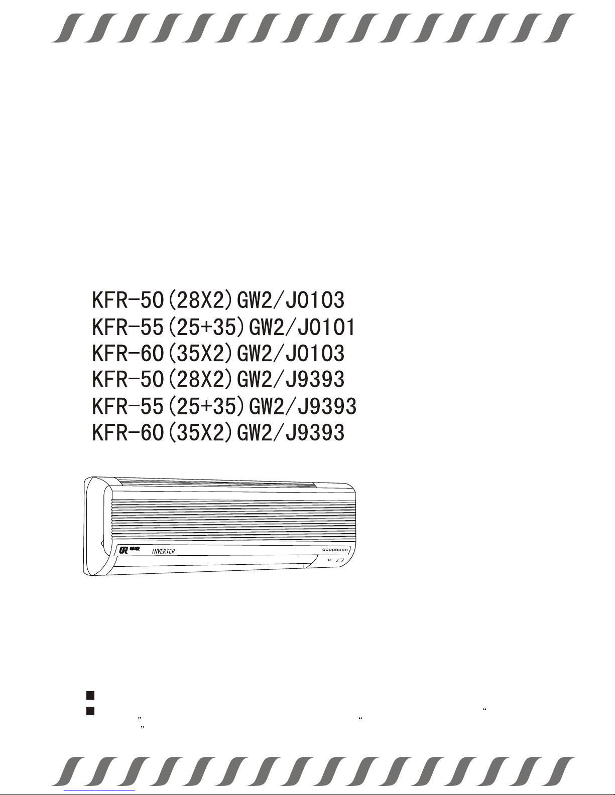
Thank you for purchasing Hualing Air Conditioner
Installation & Maintenacne Manual
Variable-frequency one-drive-two split room air conditioner series
H
U
A
L
I
N
GH
U
A
L
I
N
G
Before operation, please read the instructions carefully so that you can operate the machine correctly, and keep it
properly for future reference.
In order that your air conditioner can realize satisfied operation and perfect service, please carefully read the Guide
to User Service attached to this operating instructions, and contact the local Franchised service department of Hualing
Air Conditioner for installation. If your air conditioner were installed by non-appointed organization, the installation
quality would be difficult to be ensured while. In this condition, Company can only offer paid maintenance service.

Contents
1. Designations and functions of air conditioner parts..........................1
2. Exte rn al dim en sions ...................................................................................2
3. Designations and functions of control buttons in remote controller....4
4. Perf ormanc e pa ramete rs.............................................................................5
5. Circuit principle diagram 8
6. Refr igerat in g cycle ...................................................................................10
7. Comp uter-con tr ol princ ip le.....................................................................13
8. Auxi liary fu nc tions...................................................................................2 2
9. Inst allati on i nstruc ti ons ...........................................................................23
10.Trouble and maintenance 38
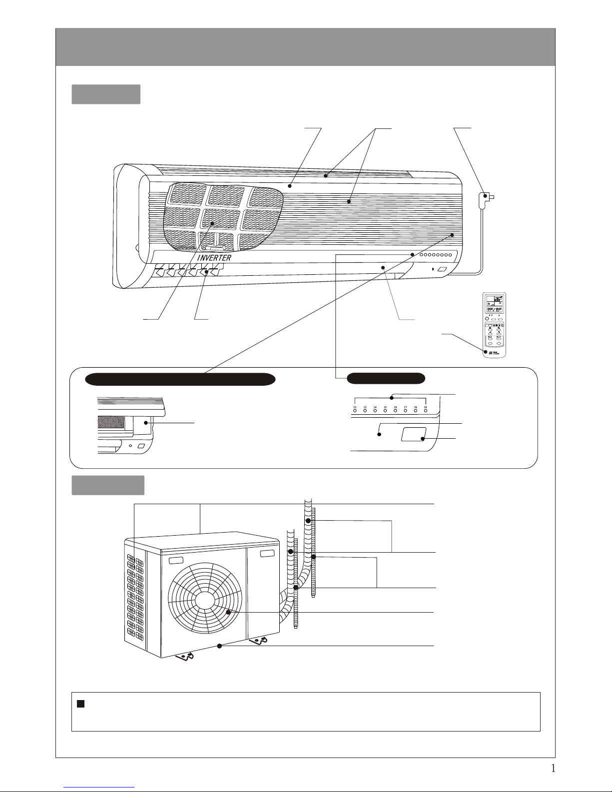
Introduction to air conditioner parts
Indoor unit
HR.
MIN.
TOO
WARM
TOO
COOL
on/off
AMPM CLOCK AMPM
CCC
Front panel
Return-air
outlet
Power plug
Filter screen
Vertical vane
Air guide
Remote controller
Operation section (with front panel opened )
Display section
Emergency operation switch
Green signal lamp
Operation pilot lamp
Remote signalreceiving window
Outdoor unit
Unit A
Unit B
Air inlet
Fitting pipe
Drain hose
Air outlet
Drain outlet
(at buttom of air conditioner)
Since the two sets of indoor unit are designed with identical structure, functions, operating method, repair
& maintenance, and troubleshooting methods, the following instructions concerning indoor unit will
involve only one of the two.
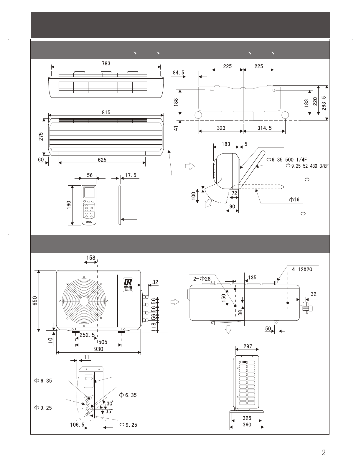
External dimensions
Indoor unit(KFR-25 28 35G/J01,KFR-25 28 35G/J93)
Outdoor unit(KFR-50W2/03,KFR-50W2/93)
Mounting plate
Power cord
Wireless remote controller
Drain pipe
Outer diameter with heatinsulating layer 28
Not less than 7
Liquid pipe
Gas pipe
Outer diameter with heat-
insulating layer 35
Two bleed holes
Fixing hole
Fitting pipe for
liquid pipe joint
Fitting pipe for
gas pipe joint
Maintenance board
Fitting pipe for
liquid pipe joint
Fitting pipe for
gas pipe joint

Outdoor unit(KFR-60W2/03,KFR-60W2/93)
Indoor unit(KFR-55W2/01,KFR-55W2/93)
External dimensions
Two bleed holes
Fixing hole
Two bleed holes
Fixing hole
Fitting pipe for
liquid pipe joint
Fitting pipe for
gas pipe joint
Fitting pipe for
liquid pipe joint
Fitting pipe for
gas pipe joint
Fitting pipe for
liquid pipe joint
Fitting pipe for
gas pipe joint
Maintenance board
Fitting pipe for
liquid pipe joint
Fitting pipe for
gas pipe joint
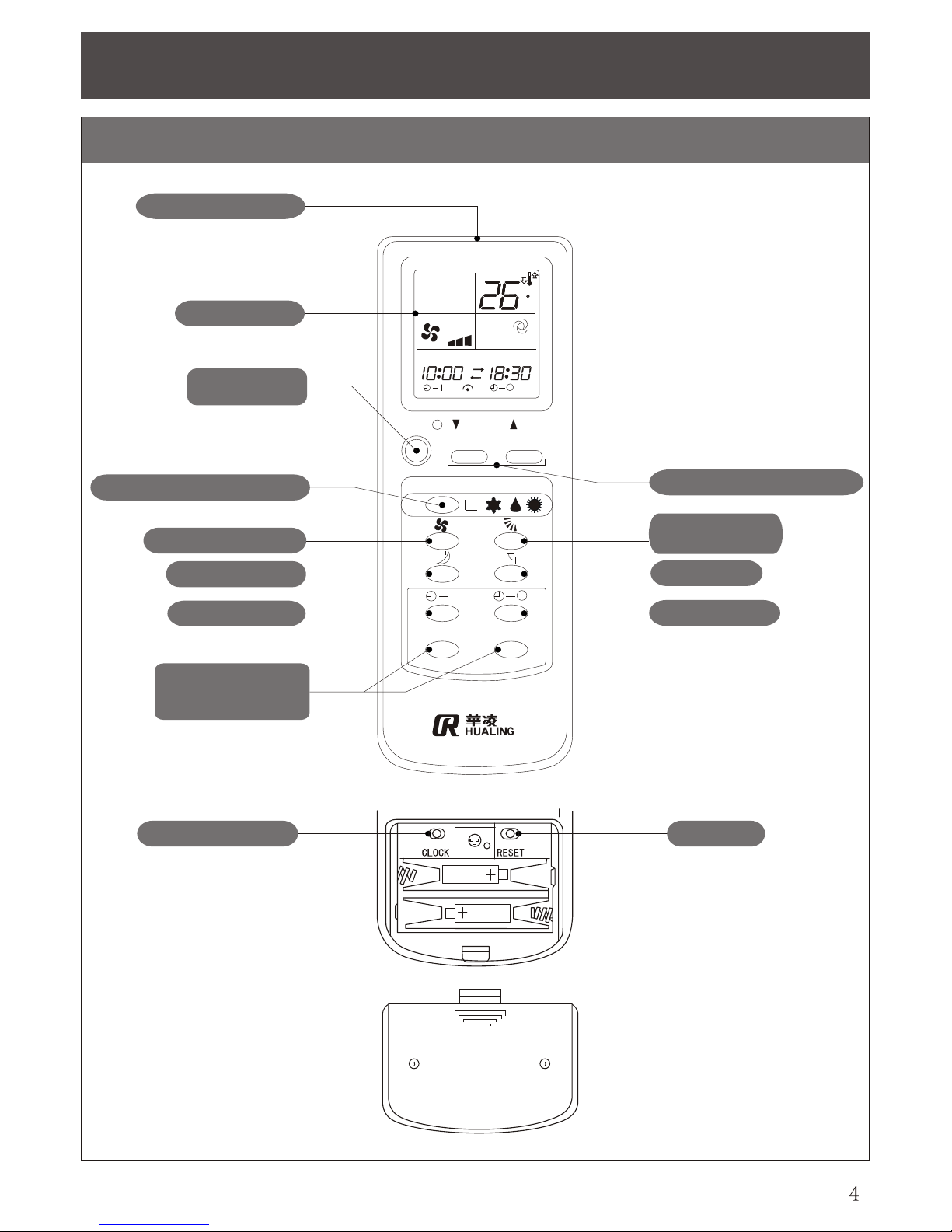
Designations and functions of control buttons in remote controller
Hanging remote series controller
HR.
MIN.
TOO
WARM
TOO
COOL
on/off
AMPM CLOCK AMPM
CCC
Signal-emitting window
Operating display
ON/OFF button
Operation-mode switching button
Air-speed option button
Sleep setting button
Timed ON button
Clock setting button
Minute setting button
(Time setting button)
Clock setting button
Temperature regulating button
Air-supply-angle
regulating button
Swing button
Timed off button
Reset button
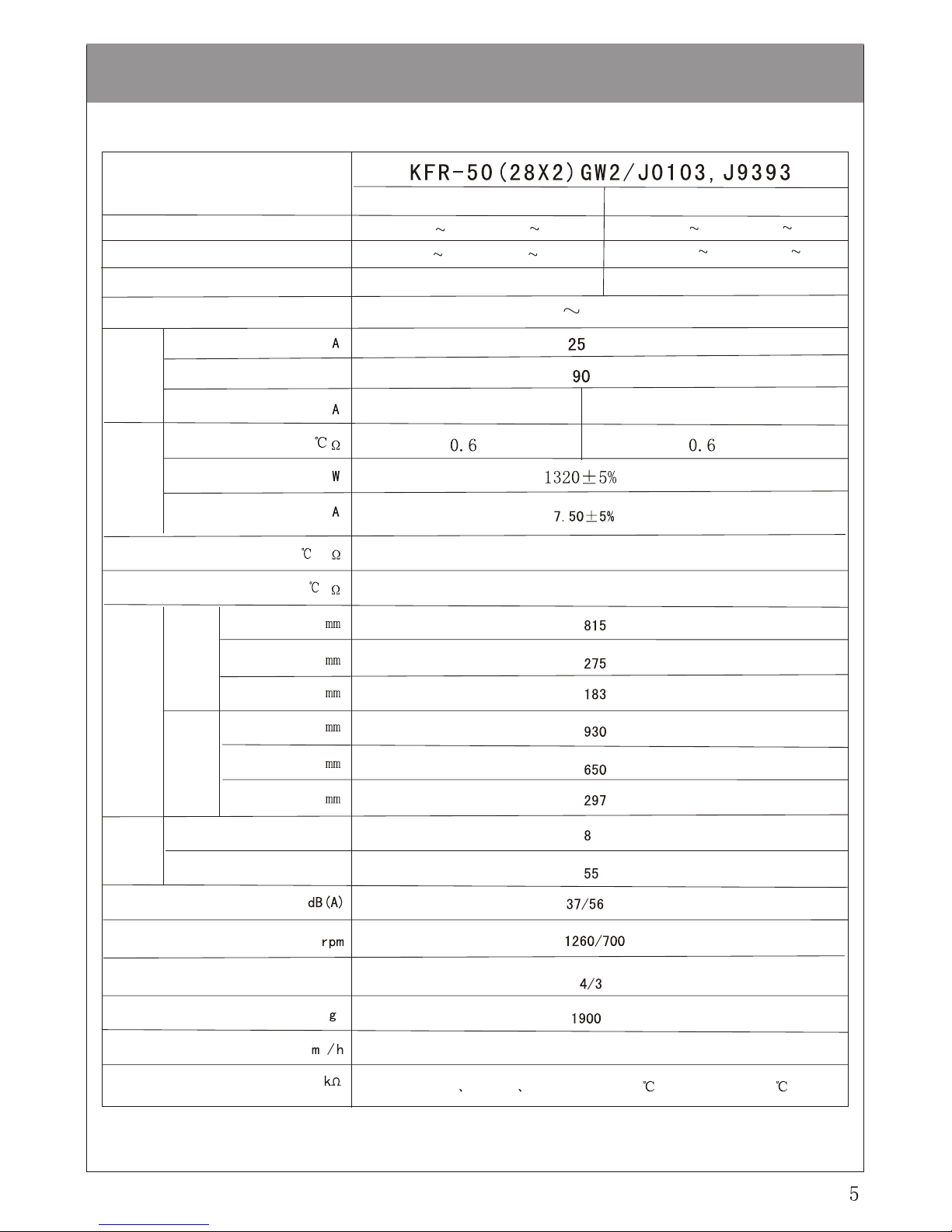
Performance parameters
Model
220V , 50Hz
4.5/7.6
9.5/11.6
0.9(0.2 1.5)/1.5(0.2 2.5)
2.8(0.3 4.0)/4.0(0.3 6.0)
5.0(1.0 6.0)/6.8(1.0 8.0)
1.85(0.4 2.5)/2.3(0.5 3.5)
3
480
%
Indoor unit kg
CN202 CN203 CN204 are 10 (25 ),CN201 is 3.3(100 )
Indoor0.35,Outdoor0.51
Indoor0.35,Outdoor0.51
Single unit
Double unit
Refrigerating capacity /heating capacity kW
Input power (refrigerating /heating ) kW
Rated current (refrigerating /heating ) A
Power supply
Electric data
Service line capacity
Power supply efficiency
Fan-motor current
winding resistance (at 20 )
Rated input power
Rated input current
Compressor
Indoor fan motor winding resistance (at 20 )
Main winding 292,secondary winding 324
Outdoor fan motor winding resistance (at 20 )
Main winding 120,secondary winding 160
External dimensions
Indoor unit
Outdoor unit
Width
Height
Depth
Width
Height
Depth
Weight
Outdoor unit kg
Indoor unit /outdoor unit noise
Rotation speed of indoor
unit /outdoor unit fan
Air-speed steps of indoor
unit /outdoor unit
Refrigerant replenishment volume
Circulated air output
Thermister
220V , 50Hz
1.0(0.2 2.0)/1.7(0.2 3.0)
2.5(0.3 4.0)/4.0(0.3 6.0)
5.5(1.0 7.0)/7.4(1.0 9.0)
2.3(0.5 3.5)/2.8(0.5 4.0)
1.3(0.2 2.0)/2.0(0.2 3.0)
3.5(0.3 4.5)/4.5(0.3 6.8)
5/10
14/16
6.5/12
550
CN202 CN203 CN204 are 10 (25 ),CN201 is 3.3(100 )
480 550
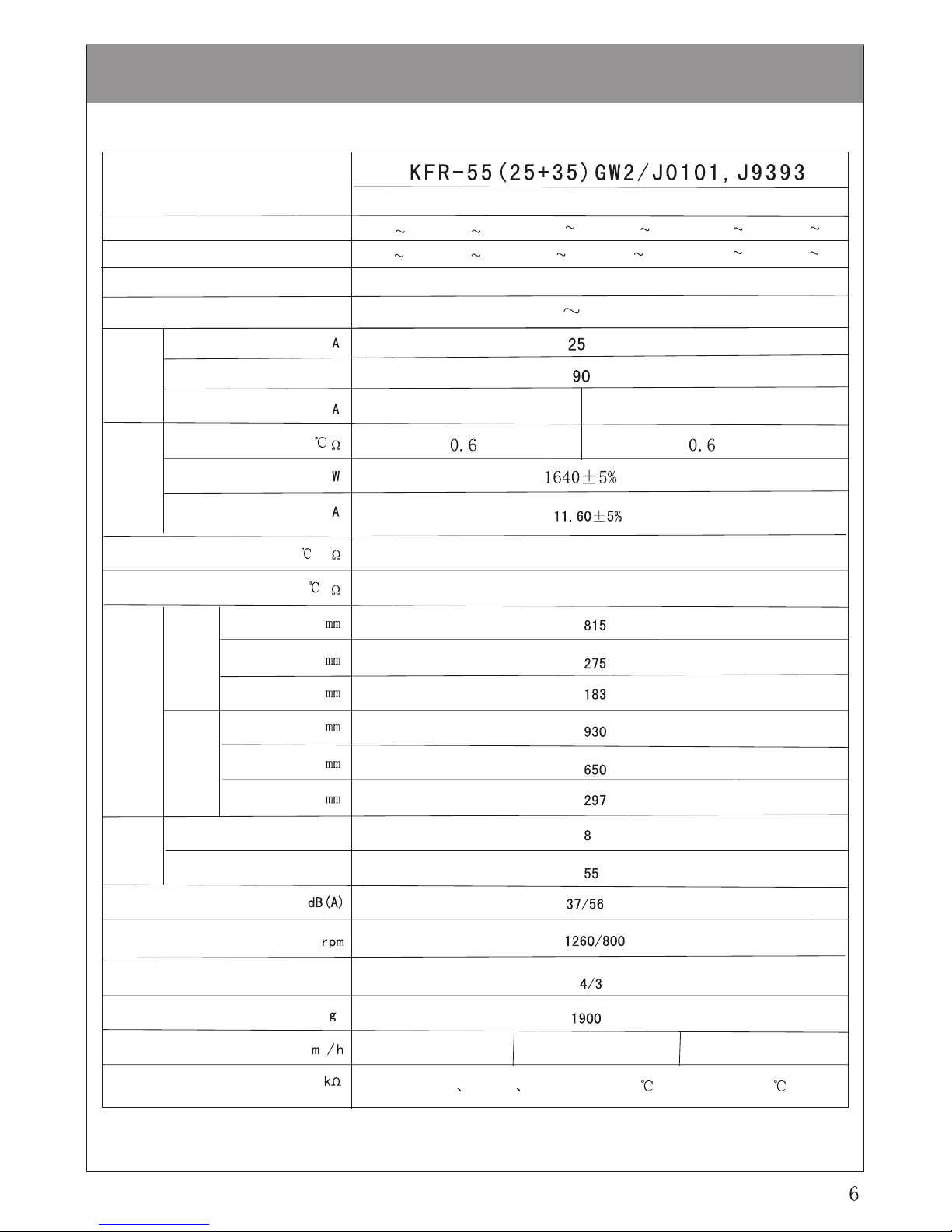
Performance parameters
Model
3
%
Indoor unit kg
Refrigerating capacity /heating capacity kW
Input power (refrigerating /heating ) kW
Rated current (refrigerating /heating ) A
Power supply
Electric data
Service line capacity
Power supply efficiency
Fan-motor current
winding resistance (at 20 )
Rated input power
Rated input current
Compressor
Indoor fan motor winding resistance (at 20 )
Outdoor fan motor winding resistance (at 20 )
External dimensions
Indoor unit
Outdoor unit
Width
Height
Depth
Width
Height
Depth
Weight
Outdoor unit kg
Indoor unit /outdoor unit noise
Rotation speed of indoor
unit /outdoor unit fan
Air-speed steps of indoor
unit /outdoor unit
Refrigerant replenishment volume
Circulated air output
Thermister
Main winding 292,secondary winding 324
Main winding 90,secondary winding 110
Indoor0.35,Outdoor0.74
Indoor0.35,Outdoor0.74
Single unit (25)
Double unit
Single unit (35)
220V , 50Hz
6.5/12.0
14.5/16.0
1.3(0.2 2.0)/2.0(0.2 3.0)
3.5(0.3 4.5)/4.5(0.3 6.8)
6.0(1.0 7.0)/7.6(1.0 9.0)
2.35(0.5 3.5)/2.8(0.5 4.0)
550
CN202 CN203 CN204 are 10 (25 ),CN201 is 3.3(100 )
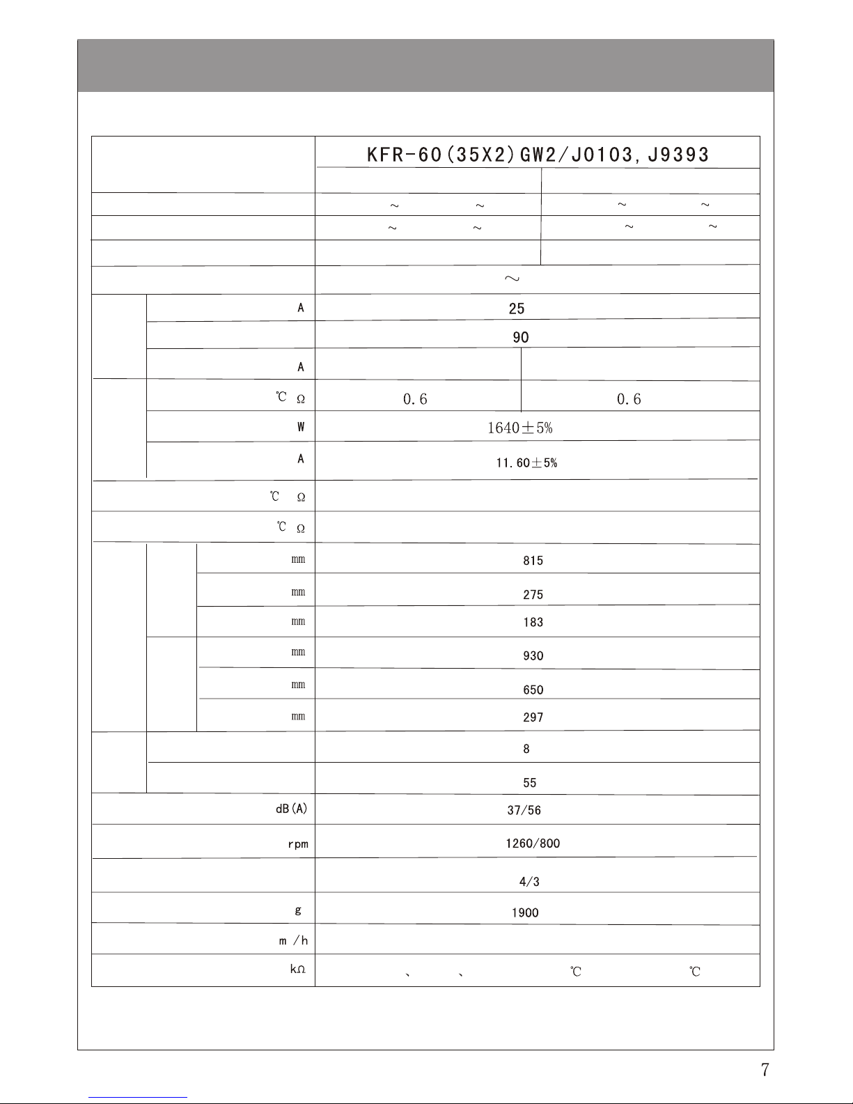
Performance parameters
Model
3
%
Indoor unit kg
Indoor0.35,Outdoor0.741
Indoor0.35,Outdoor0.74
Single unit
Double unit
Refrigerating capacity /heating capacity kW
Input power (refrigerating /heating ) kW
Rated current (refrigerating /heating ) A
Power supply
Electric data
Service line capacity
Power supply efficiency
Fan-motor current
winding resistance (at 20 )
Rated input power
Rated input current
Compressor
Indoor fan motor winding resistance (at 20 )
Main winding 292,secondary winding 324
Outdoor fan motor winding resistance (at 20 )
Main winding 90,secondary winding 110
External dimensions
Indoor unit
Outdoor unit
Width
Height
Depth
Width
Height
Depth
Weight
Outdoor unit kg
Indoor unit /outdoor unit noise
Rotation speed of indoor
unit /outdoor unit fan
Air-speed steps of indoor
unit /outdoor unit
Refrigerant replenishment volume
Circulated air output
Thermister
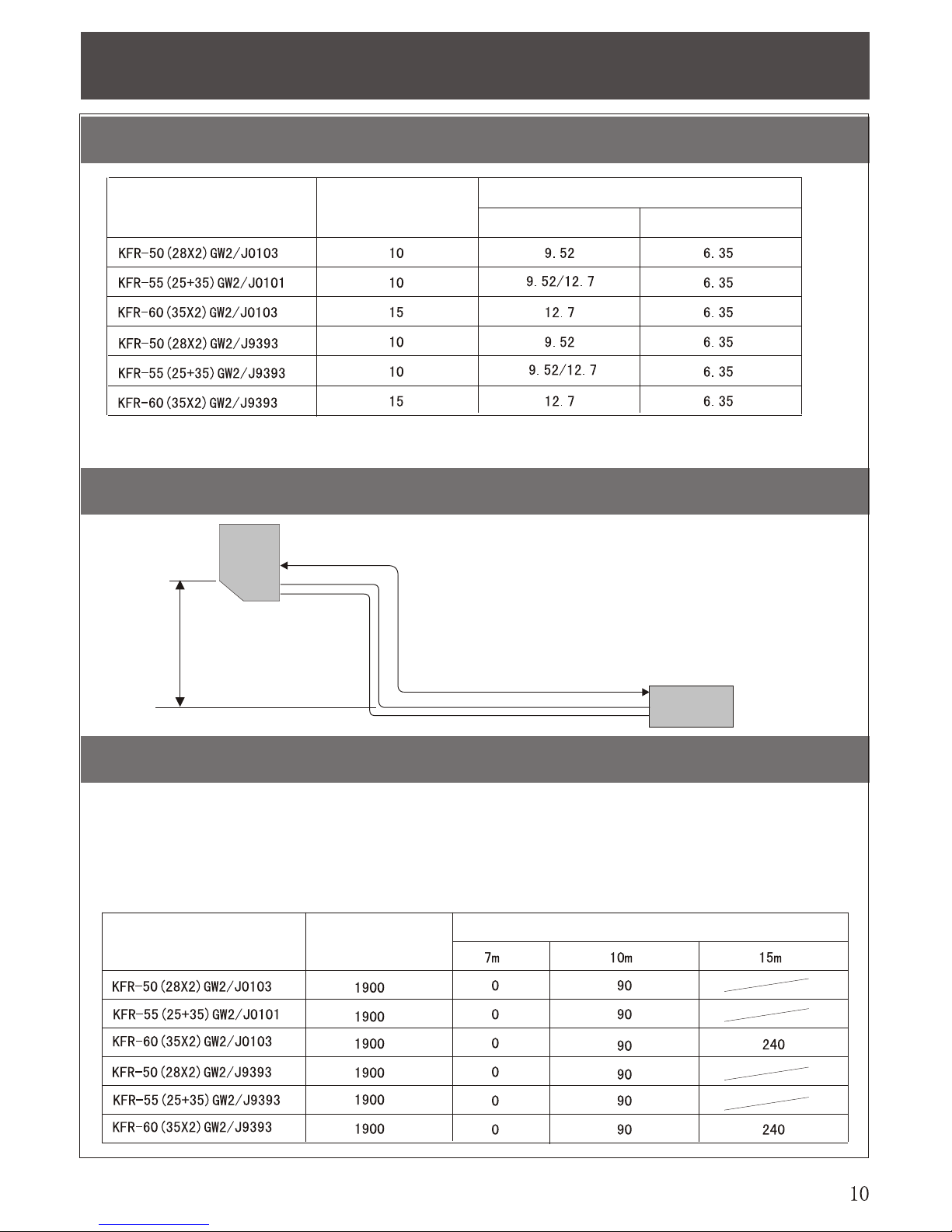
Refrigerating circuit
Maxinmum length of fitting pipe
Maximum height difference
Refrigerant replenishment (R22)
Model
Maximum length of extended
fitting pipe A (m)
Outer diameter of fitting pipe : (mm)
Liquid pipe
Gas pipe
Indook
uint
Outdook unit
Maximum length of extended fitting pipe A
For example:
Model
Extended length of fitting pipe and replenishing volume
Replenishing volume (g)=30g/m X(A-7)
A indicates length of fitting pipe (m), and its maximum value is 10m or 15m.
Maximum height difference
5m (regardless either unit is
higher)
Connection fitting pipes of our indoor/outdoor unit are divided into the sizes 3m, 5m, and 7m. If the length of fitting pipe is
over 7m, it is required to replenish refrigerant.
Replenishing volume of refrigerant should be calculated according to the following formula:
Existing refrigerant
volune (g) of outdoor
unit (outdoor unit)
Microcomputer control principle
Wireless remote controller
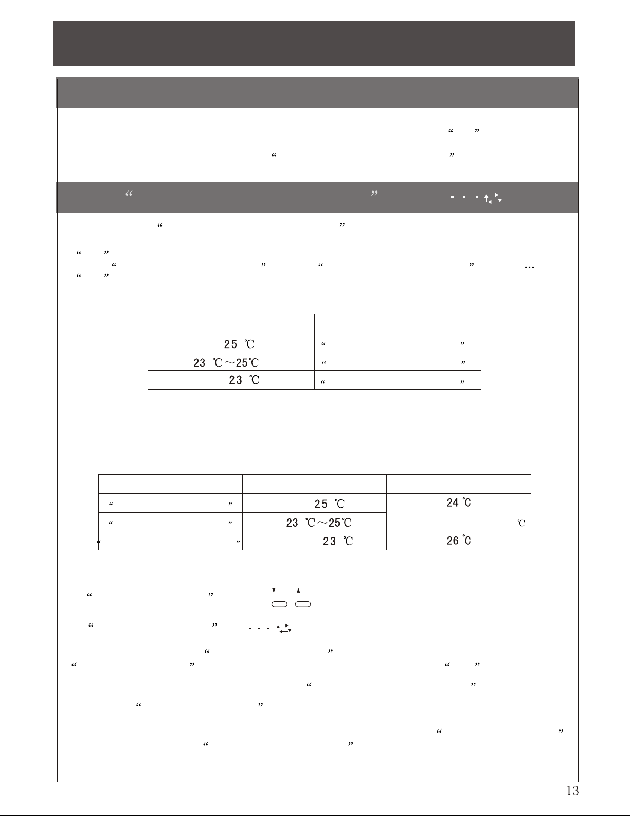
Run of temperature-regulating operation (I FEEL )
Initial room temperature Operation mode
Refrigerating operation of
temperature-regulating operation
Over
Below
CInitial room temperature minus 2
Operation mode Initial room temperature Initial room-temperature setting
TOO
WARM
TOO
COOL
" Once the control content is set properly, turn on the power supply switch, identical operation will be repeated.
"
Press a button in remote controller, and the indoor unit will give out a sound toot when it receives a
signal.
"
When you want to restart up the unit, the function for 3-minute delay protection will be activated, and the
compressor cannot be started up within 3 minute after shutdown, avoiding overload.
(I) Utilization of temperature-regulating operation
1. Press ON/OFF button in remote controller, operation pilot lamp of indoor unit is on, and it gives out a sound
toot .
2. Utilize peration-mode switching button to select emperature-regulating operation (I FEEL ), a sound
toot can be heard.
3. Operation mode depends on initial temperature at startup, and the mode setting cannot be changed by later
variation in room temperature.
Dehumidifying operation of
temperature-regulating operation
Heating operation of
temperature-regulating operation
Note: 1. In timed ON mode, operation mode depends on room temperature at startup.
4. Initial temperature setting depends on initial temperature within the first 2 minutes after air
conditioner startup.
Refrigerating operation of
temperature-regulating operation
Dehumidifying operation of
temperature-regulating operation
Heating operation of
temperature-regulating operation
Below
Below
Over
5. Temperature regulation button ( )
In temperature regulation (I FEEL) mode, temperature setting will be preset by
microcomputer according to initial room temperature (as shown in table above). In addition, if you feel
too cold or hot, just use temperature regulation button to control temperature setting. Press
temperature regulation button, and the indoor unit will give out a sound toot .
Intelligentized logic control (which only runs in emperature-regulating operation mode)
If you press temperature regulating button (TOO COOLor TOO WARM), microcomputer will
determine the user's temperature favorite and automatically preset temperature according to the
detected room temperature and the frequency at which the user presses temperature regulating
button; this is referred to as intelligentized logic control
 Loading...