

Huafengdongli R4105T, R4105T1, R4105T6, R4105ZT, R4100ZD Operation And Maintenance Manual
...
HUAFENGDONGLI
R
Series
Diesel
Engine
OPERATION
AND
MAINTENAN
ANUAL
Shandong
Weichai
Huafeng
Power
Co.,
Ltd
Preface
R series diesel engine is a four
~troke
,vertical, water-cooled, inline and direct injecting combustion chamber type,high-speed diesel engine. Thjs series diesel engine is
specially designed for our country by Ricardo Consulting Engineers Co.
of
Britain,
and manufactured and developed firstly by Ricardo Consulting Engineers
Co.
cooper-
ated with Shandong Weichai Huafeng Power
Co.
, Ltd.
It'sanew
generation prod-
uct instead
of
the same type diesel engineinour country. This type diesel engine
possesses performances
of
high power,economy and easy starting, under the envi-
ronment
with
temperature higher than
-lOOC
,the dieael engine can be easily started
without preheating. The first overhaul period is 8000hrs. Its reliability and service life
achieved a advancde level among the same kind products all over the world.
Rseries diesel engine covers 8 types
as:
both four -cylinder and six-cylinder
with
bore
of
lOOmm,both four-cylinder and six-cylinder with bore of
l05mm,and
every style
has
two
models of matural aspirated and superchareged.
RIOS
series is bore -en-
larged from
Rl00 series,besides piston,piston ring,piston pin,cylinder liner,cylinder
liner seal ring and injection pump,
all
other parts
can
be exchanged between both
two
types of diesel engine.
R series diesel engine features easy adaptation
to
meet the various needs
of
matched equipments,accordingtothe requirement of users. It can be furnished
with
hydraulic pump for Ifting and steering purposes, air compressor and vacuum pump
for breaking purposes
and full power take-off from the front end
of
the crankshaft.
Through being changed for some
of
its parts accordingly, it can be used
to
match
with truck,tractor,small power generating station,engineering machinery,agricultru-
al
machinery,irrigation machinery,drilling machinery and so on. The output range
of
various version
of
R series diesel engine
is
35
KW
-125
KW
,its rated speed is 1500r/
min
-2800r/min.
The moder,its make-up rule and the meaningofthe symbol for ev-
ery type is
as
follows:
R
6 100 Z D 1 2
(1)@@
@@@
(j)
CD:
distinguish symbol, Expressed
with
number sequence
~:
Version symbol ,expressed
with
number sequence
@:
application featrue symbol,expressed
with
alphabet
no alphabet:for common usage; T:for tractor; G:for engineering machinery;
Q:
for vehicle;D:for generating
set;
C:for marine usage;P:for power take-off unit
@:
construction feature symbol,expressed with alphabet;no alphabet:for natural
#85-
pirated model;
Z:for
turbocharged model.
(S):cylingder bore(
mm)
@:cylinder number
(J):series symbol;stand for imported from RICARDO
This operating manual mainly introduces common usage type. For various versions;

only show their different features. As technology progresses and usage expands,the
aengine
wi'l be modified
and
improved from time
to
time,therefor the product
s'up-
plied hereafter may
be
slightly different from that describedinthis manual and the
users
are kindly advised to notice it.
Being obtained
as
the accidental test result, the characteristic
c.urvesinthe manual
are
only supplied for reference.' And the pictureinthe manual
cant
be the accord-
ance
of
check upon delivery.
/
The
manualiscompiled by Wang Jinghai, Zhao Ruian,
Yang
Lin,
Sun
Chuanhai,
Wang Luhai,
Dou
Yuxiang, Jiang Bo,
Yu
Caihong,
Liu
Taicheng, Zhuang Longping,
Wei Zhiyou,
Du
Zhijun, advised byLiPeiyan, Chen Ling,
Hao
Sixian, and finally ex-
amined and approved by
Chen
Ling.
For
the limit
of
the compilers, there may be
mistakes
in
the manual, if you find any, please point out so that they can be correc-
ted. Also, it will be appreciated if
you give your suggestions about our products.
The
compilers
June,
2005.
Attention
1. The diesel engine operators must familiarize themselves
with
this manual as well as engine
construction and strictly follow the procedures
of
operation
and maintenance especially the regulations for safety operation described
in
this manual.
2. Before operating
an
engine at full load
,the
60 hours running
in
should be carried
out
as
specified
in
the manual.
3. Increase its speed gradually after stating a cold engine,never
let it run
at
highs speed abruptly, and
don't
stop
the
engine
instantly while its cooling
water
is still
hot,
also
don't
let
the
engine running long
time
without
load.
4.
If
the
ambient temperature falls below +
SOC
,drain
the
cooling
water out
of
the radiator, the lubricating oil cooler and the
diesel engine itself completely after stopping the engine.
Con-
tinuous keeping the
water
in
the oil cooler should be forbid-
den.
5. Never run the diesel engine
without
and air cleaner so as
to
prevent the unfiltered air from entering the cylinders.
6. The engine
must
be filled
with
specified grade fuel and lubri-
\eating oil,and
a special
and
clean container for each oil should
be used. The fuel oil should
be settled for
72
hours and fil-
tered before using.
7. The inspection and repair
of
the components
in
electrical sys-
tem
must
be carried
out
by the person
who
has a good
knowledge
of
electricity.
8. If the
water
pump is
without
oil filler,
its
a ??? bearing wa-
.
ter
pump,
and neednt add lub oil to it.
9. Be sure
to
use
water
- cooling diesel engine. Please refer
to
P.43 for details.
10. The working environment
of
the diesel engine should be
well ventilated
to
avoid being polluted by
waste
gas or
smoke.
11.
The
power
rati~g
and
amending
of
the
diesel
engine
is
ac-
cording
to
GB6072.1"-2000 the first section
of
reciprocating
internal combustion engine:
sta"ndard
basic condition, the
rating
and
testing method of power, fuel consumption and
engine
oil
consumption.
12.
The
manufacturing of the diesel engine
is
according to the
common technical requirement for low
and
middle level
powered diesel engine
in
JB/T8895~1999
and
Q/WCGOOS
-2002R
series diesel engine enterprise standard.
13.
The
No.
of production license of this series diesel engine
is:
XK06-205
- 00160,
XK06
- 205 - 00161,
XK06
- 205 --
00279.
14.
The
position of safety warning marks:
(1)
Theres a guard against burning mark at the end of the
cylinder cover which
is
beside the exhaust manifold of the
diesel engine.
(2)
There~
a guard against fire mark
at
the ail filler.
(3)
Theresa guard against twinning mark
on
the inlet man-
ifold.
(
4)
There's a flywheel rotating direction mark
on
the fly-
wheel housing.

Contents
1.
Longitudinal sectional drawing for R4100,
R410S
diesel
engine(
Fig.la)
.•....•.• 1
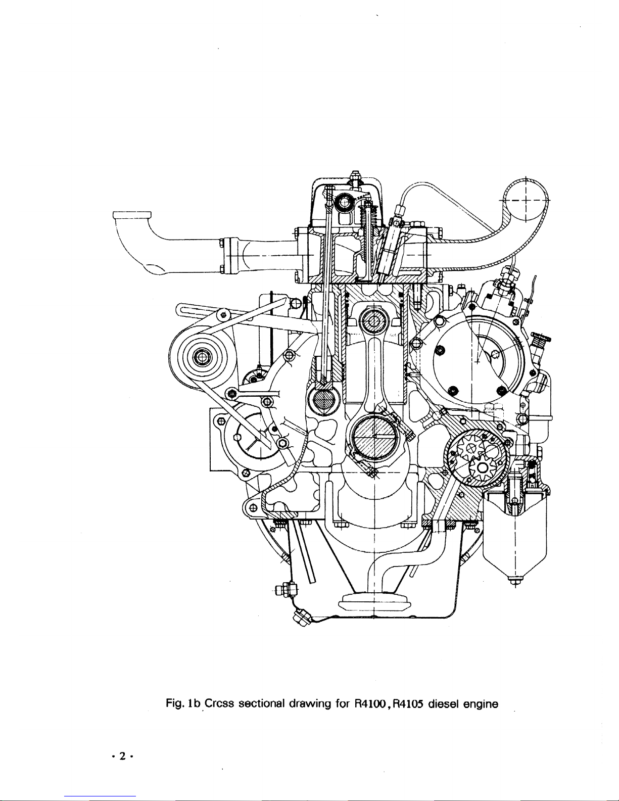
Cross sectional drawing for R4100, R4l05 diesel engine(
Fig.1b)
2
2. Longitudinal sectional drawing for R6100,
R610S
diesel engine(Fig.
2a)
3
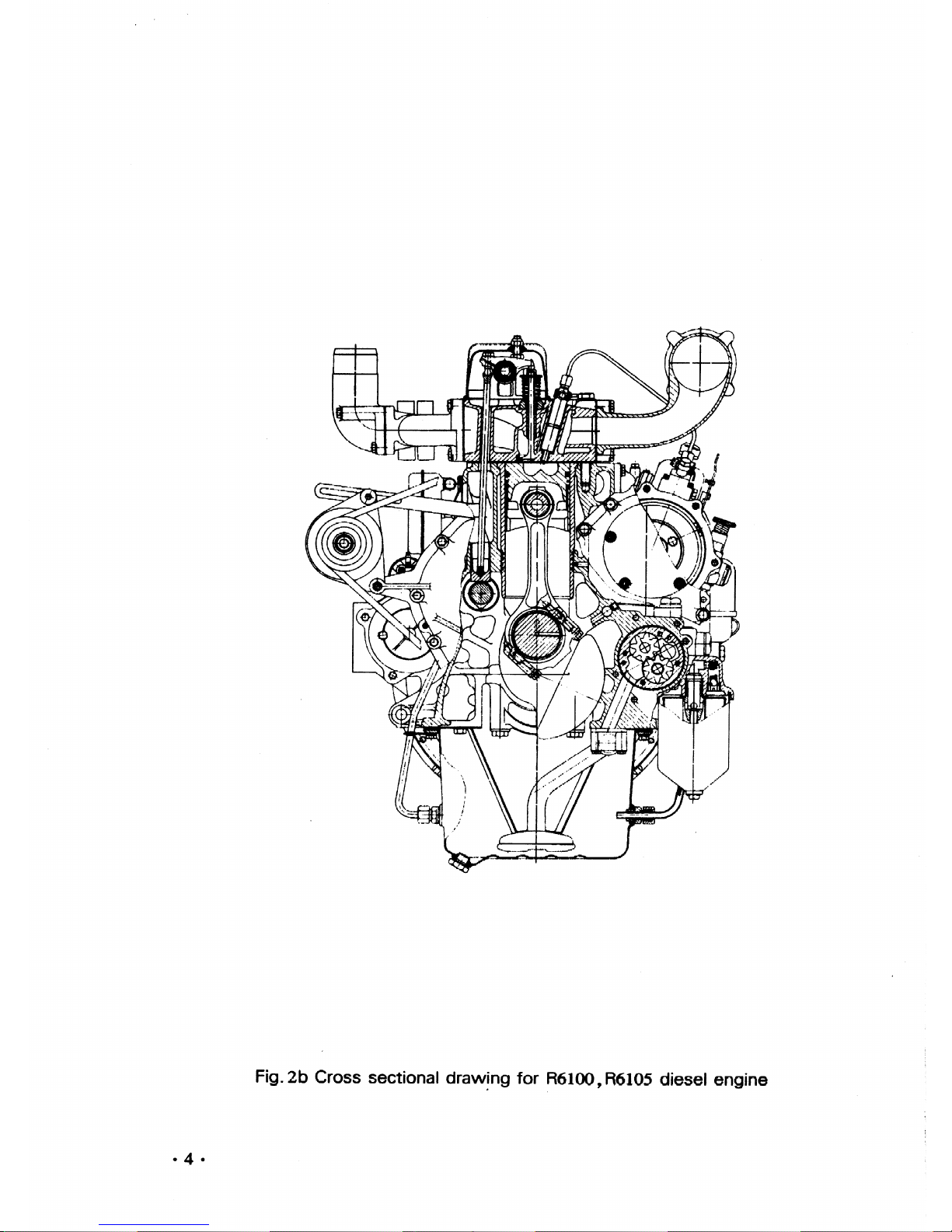
Cross sectional drawing for R6100,
R610S
diesel engine( Fig.
2b)
4
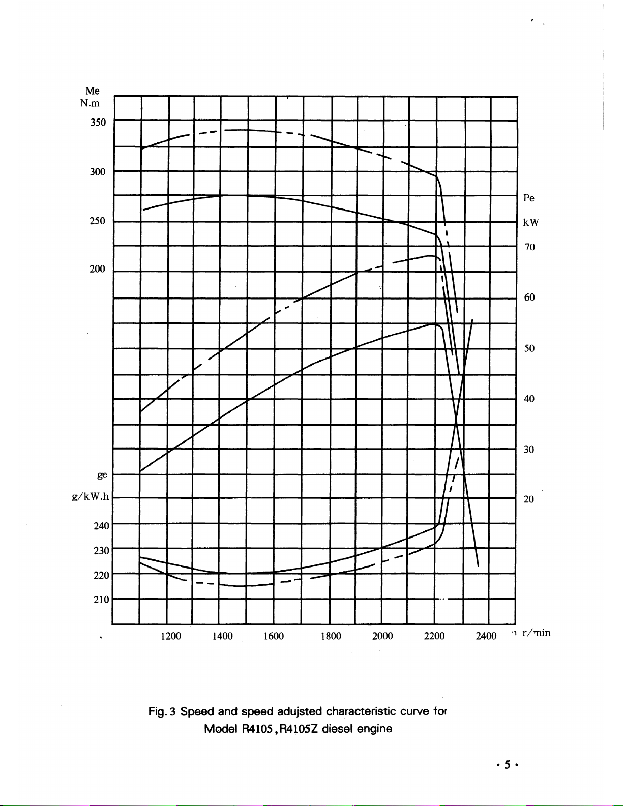
3. Speed and speed adjusted characteristic curve for Model
R410S,
R410SZ
diesel engine(
Fig.
3)
5
4. Speed and speed adjusted characteristic curve for Model
R610S,
R610SZ
diesel engine(
Fig.
4)
6
5. Speed adjusted characteristic curve for Model
R4105T
and R410STI
diesel engine for tractor usinn(Fig.
S)
u
•••••••••••••••••••••••••••••••
7
6. Speed and speed adjusted characteristic curve for Model
R410SG
diesel engine
used for engineering machine (Fig.
6)
......................•...........•..•.............
8
7.
Speed and speed adjusted characteristic curve for Model R6105G, R610SGt,
R610SZG
and R610SZGl diesel engine used for engineering machine (Fig.
7)
···9
8. Load characteristic curve for Model R6100ZDl and
R6100ZD2
diesel engine for
generating sets (Fig..
8)
· · ····..· ·..·
....•......
~
·
10
9. Propellant characteristic curve for Model R4105C, R410SCl,
R610SC
and R6105Cl
marine diesel engine (Fig.
9)
11
10.
Load
characteristic curve for Model
R41OSP,
R410SZP
and
R610SP
diesel engine
for generating unit(
Fig.
to)
12
CHAPTER
I.
Main Technical Specifications
and
Data
for the
diesel engine 13
§ 1 Main techincal specifications
§ 2 Range for various temperature and pressure
§ 3 Tightening torque
of
main bolts
§ 4 Main adjusting data
§ 5 Matxhed clearances and wear limit
of
main parts
CHAPTER
II.
Main structure of diesel engine .......•................ 28
§ 1 Cylinder head assembly
§ 2 Cylinder block and relatea
assemoly
§ 3 Camshaft assembly
§ 4 Piston and connecting rod assembly
§ 5 crankshaft and flywheel assembly
§ 6 Transmission
system
§ 7 Intake and exhaust
system
§ 8 Fuel
system
§ 9
Lubricating
system
§ 10 Cooling
system
§
11
Electric
system
§
12
Air
compressor assembly
§
13
Clutch assembly
CHAPTER
m.
Operation of diesel engine 54
§ 1 Transportation,installation,storage and preservation
§ 2 Fuer,oil and cooling
water
§ 3 Preparation before starting
§ 4 Starting
§ 5 Running
§6
Stopping
§ 7 The wearing in
of
the
diesel engine
§ 8 Safe and technical operationg rule
CHAPTER
N.Technical maintenance of diesel engine 61
§ 1 Working day maintenance
§ 2 First grade technique mainenance
§,3 Second grade technique maintenance
§ 4 Third grade technique maintenance
§ 5 Technique mauntenance on
winter
working
CHAPTER
V.
Trouble
and
remedy method 63
§ 1 Start failures
§ 2 Unsteady running
§ 3
Output
is instfficient
of
drops suddenly
§ 4 Abnormal noise during engine iperation
§ 5 Abnormal exhaust
smoke
§ 6 Insufficient oil pressure
§ 7
Oil
temperature
too
high
§ 8 The temperature
of
used cooling
water
too high
§ 9
Trouble
in
the
injection
pump
§
10
Insufficient fuel supplyofthe fuel delivery pump
§
11
Injector in trouble

§
12
Governorintrouble
§
13
Engine stops suddenly
§
14
Charged dynamo outoforder
§
15
Starting motor beintrouble
§
16
Governorintrouble
§
17
Turbochargerintrouble
§
18
Air compressorintrouble
§
19
Clutch in trouble
CHAPTER
VI.
Installation instruction for diesel engine
generating set
76

.Fig.laLongitudinal sectional drawing for R4100,
R4105
die~el
engine
• 1 •
~-=-
\
\
~~~--1:I-..L.-'~--~
~AlIIIJ/'r'7"7""'7'/.L.-J
Fig.lb.Crcss
sectional drawing for R4100,R4105 diesel engine
· 2 ·

Fig.2a longitudinal
s~ctional
drawing
for R6100, R6105 diesel
engine
· 3 •
· 4 ·
Fig.2b
Cross sectional
draw~ng
for
R6100,
R610S
diesel engine
Me
N.m
350
300
250
200
ge
g/kW.h
240
230
220
210
~
.--
....
-
...
~
~
~
1"""-
.....
~
',,-
~
~
~
~
----.
j'----....
\
I~
~
...............
.......
........
~
i\ "
----
-------
~1\
---
l/
v
~\
,
\\\
~;
./
V
~
~
~~
il
/
~
/'
~V-
~
\'\~
v
V~
/
v
\ J
./
V
V
V
~
/
v
J\
V
I
/'
1/
~
/I
\
~
/
r;
\
~
F:::::-
~
~
~"""".
,,.,,..-
...............
~
---
~
----
~
r-----
~
.--
-----
--
,.
Pe
kW
70
60
50
40
30
20
1200
1400
1600
1800
2000
2200
2400
'1 r/
TTl
in
Fig. 3 Speed and speed adujsted cha.racteristic curve for
Model
R4105,
R410SZ
.diesel
engine
• 5 •
Me
N.m
SOO
450
400
350
ge
g/kW.h
240
230
220
210
..--
-...
------
......
~
--.....
"
'-
-""'
1\
,
I
----
~
--....
r-............
,
.---
~
~
""'-,
I
\
~
I
------
~
, \
I
."
I
I
~"
I
~
,
~
~
I
~
~
-
"
V-
~
..,-
I
~/
~
~
V
~
, I
~
/
~
~
~
./
J,\
,\
~
\
"-
~
~
'/
\
~
~
r----.
~
~
/""'"'"
\
-
-----
-
."...
--
--.
_
...
-
-
Pe
kW
110
90
70
50
30
1200
1400
1600
1800
2000 2200
2400
n
r/min
• 6 ·
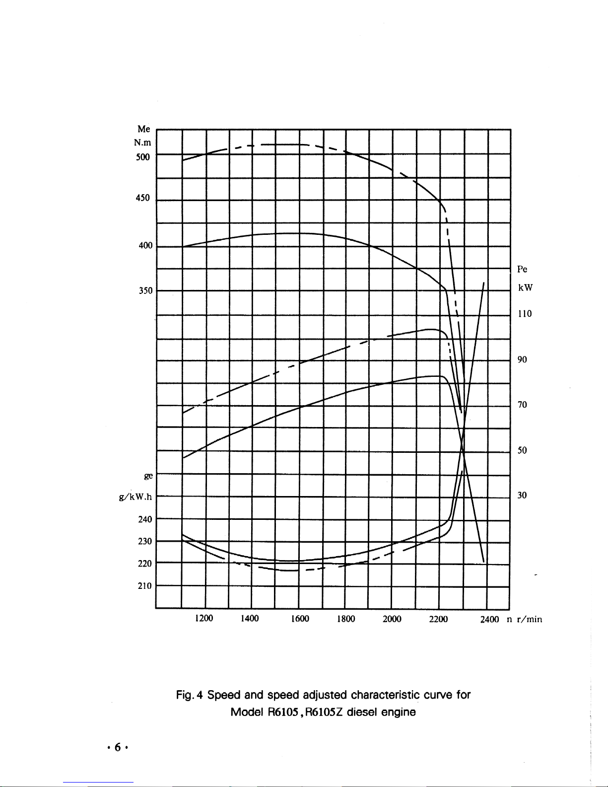
Fig.4 Speed
and
speed adjusted
characteristi~
curve for
Model R6105,
R6105Z
diesel engine

n r/min
2200
2000
1800
1600
1400
1200
ge
g/kW.h
280
270
260
250
240
230
220
210
--
-
--
---
----
-
""'"""-
/
/
J
4
/
V,
1/
/
./
~
.,
~
~
"",'"
~,...
-~
"
~-
\
./
~
~
\
I
i\
~
"
A
V
I'
~
~
"
~
A
~
,
'-
/?
~'
~
~
..
/.
~
~
~
~
V'
~
"'f'::
~
~
~
0
v
l":
.....
-.
1(.--
.-/
~
........
~
~
t/"
~
Me
N.m
280
240
200
160
120
80
40
10
20
30
40
Pe
kW
Fig. 5 Speed and speed
adjusted
characteristic
curve
fo~
Model R4105T and R410STl diesel engine used
for
tractors
· 7 ·

Me
275
250
225
200
glkW·
h
240
230
220
210
~
~
---....
~
y
~
"'
K
\
,
•
1\
/
~
n
\
/
'/
\
V
~
,
~
V
l A
V
:, 1
/
t
~
V
1\
.
r
J
I
J
,
~V
v
~
.............
r----.
~
~
\
~
-~
Pc
kW
60
50
40
30
20
1000
1300
1600
1900
2200
2500
2800
n
r/min
· 8 ·
Fig. 6
~peed
and speed adjusted characteristic curve
for
Model
R4105G
diesel engine used
for
engineering machine
Me
N·ro
500
450
400
375
350
L
g/kW.
h
240
230
220
1.---
1--
---I
--............
/
~
...............
"
'-
"'"
t'.~
\
"\
\
\
,
~
~
---
r-----.
\
\
~
~
,
,
."..,.-
...
-
-
- .
~
...
--~
~
1
~
.......
.........
~
~
\
...........
\\
1\
J
,
,
\
,
,
__
'-'1
-
,
J...:
~
,
\
.-.-'
".
.-Ii'
,...-:
~
/'
\
\
\ \
".
,
~
"",
I
,
-
I
~
........+
.......
....-r-
,
i\
I
,
,,-
","
,.....",-
~
\
..
,'
/
".
,.
~
\
~
~
~
~
.,..-
........
~
\
J
',\\
~~
~
~
~
..
~
\ I
\
I
I'
\'
.JII'
,
,
~.
-'I
I
,
"
"
i
\
,
,
,.
JI
\\
1\
\
I
I \
\
J,
,....,...
[/
l1
..-.
,
~
....
V-
"
::::::
~
,........
~
----
----
~
......
•
........
......
~
""..,.-
\
1-
....
Pe
kW
110
90
70
50
1200
1400
1600
1800
2000
2200 2400
2600 n
T/min
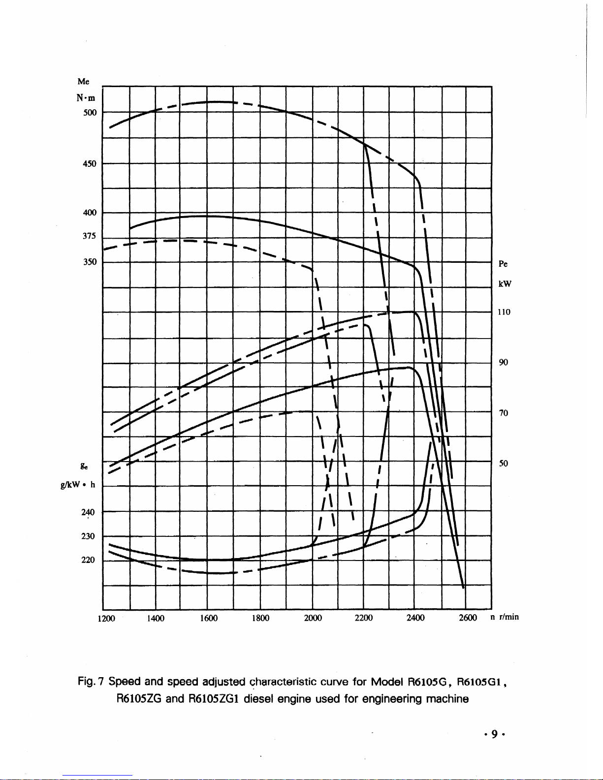
Fig. 7 Speed and speed adjusted
~haracteristic
curve
for
Model
R6105G,
R6105Gl,
R6105ZG
and R6105ZGl diesel engine used
for
engineering machine
ge
g/kW.h
360
340
320
300
280
260
240
220
~
\
\
\
\
1500r/min
~
\
~
~
V
~
~
r\
~800r/min
\
\
~
v
~
1\
\
'\
1\
1\
"
"-
~
~
"
"'
'..
~
'",
~
~
..............
......
:::----
~
t'----.
L-
~
20
40
60
80
Pe
kW
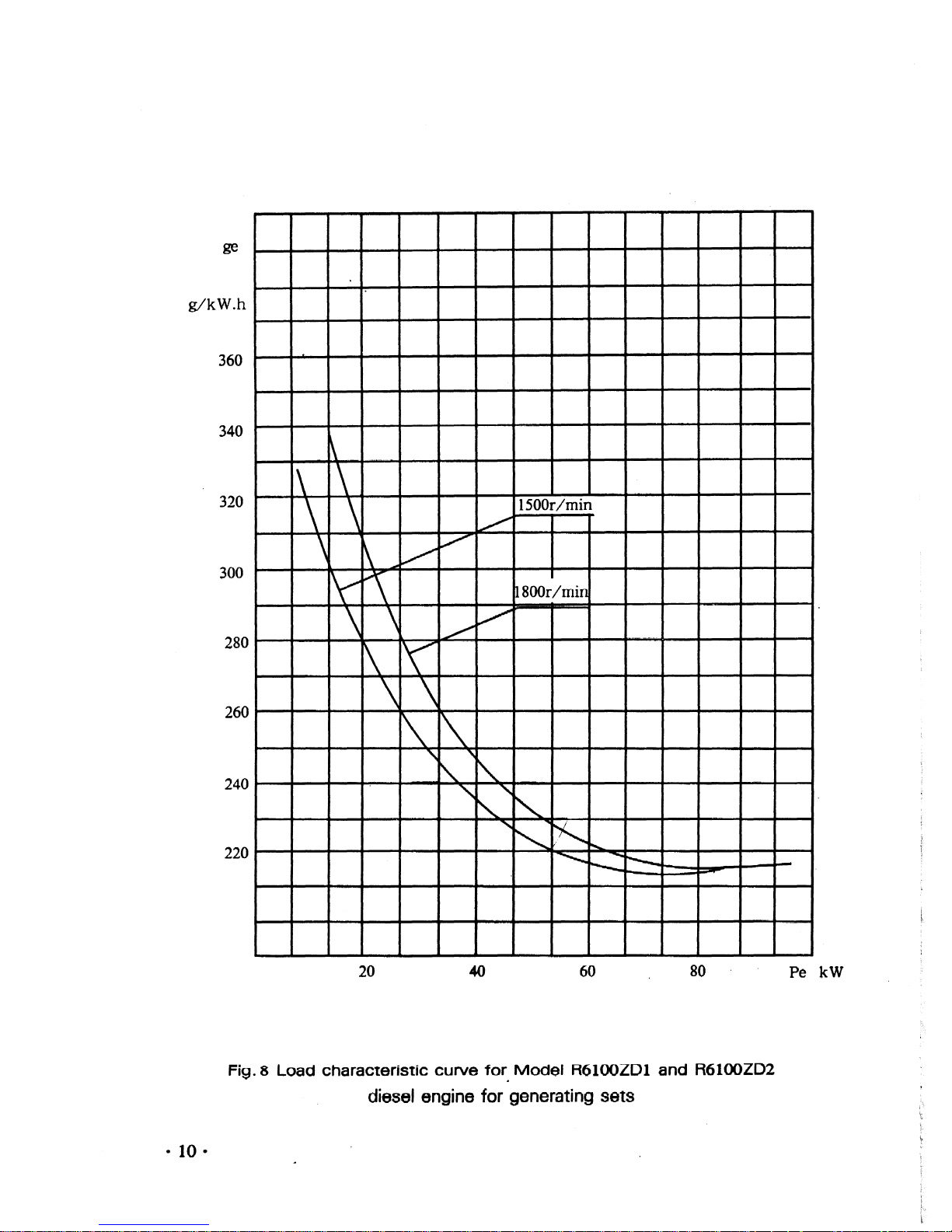
Fig. 8
Load
characteristic
curve
for.
Model
R6100ZDl
and
R6100ZD2
diesel engine for generating sets
• 10 •
Pc
kW
70
50
40
30
20
10
..
~
\~
~\
"
\
~
\\
,
\\
,
\
\
\
1/
\
\
\
\
,
~\
/
\
~.
\
~'\
~
\ \
I
\
i
'\
~
,
~.
.
/
If
\.
\
,'
~
~
'I
/
~
"
J
,
\
(.
,
~
,
,
,
~
/
,
"
J
'"
I
/
I
r'...:::
~
~--
"
I
...
~
-
~
~
-
"
'I
4
"
~/
;.
...
'
/
I
~
V
-..
l.C.:....-
.,.,
V
4
--
~
/
/
~
/
l;'
17
V
/
J
/
/
~
,
V
V
V
...
/
/
/'
:/
r,.
~
'f'
V
./
~;
~
~
~
"",
....
",.
V
".
~
~
~
glkw.
h
340
320
300
280
260
240
220
1000
1200
1400
1600
1800
2000
n r/min
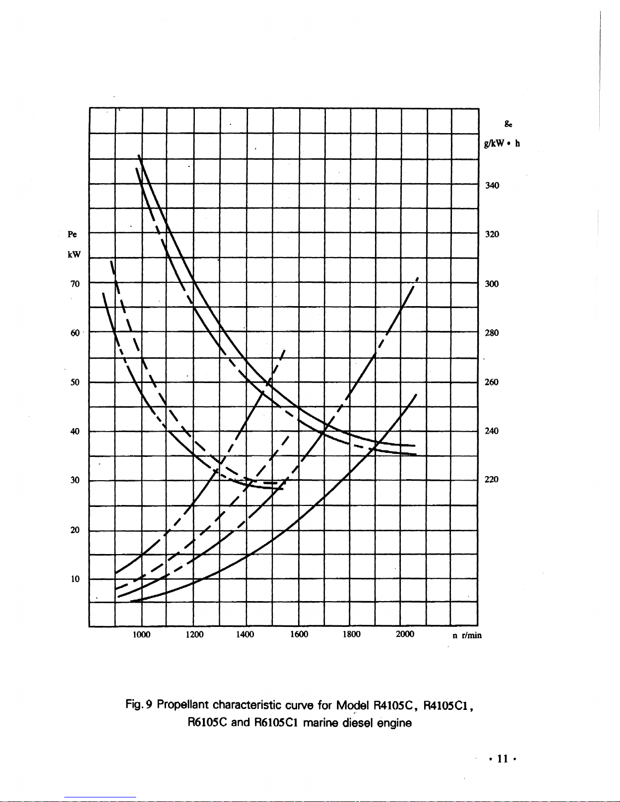
Fig.
9 Propellant characteristic curve for
Mo~el
R4105C, R4105CI,
R610SC
and R610SCI marine diesel engine
•II•
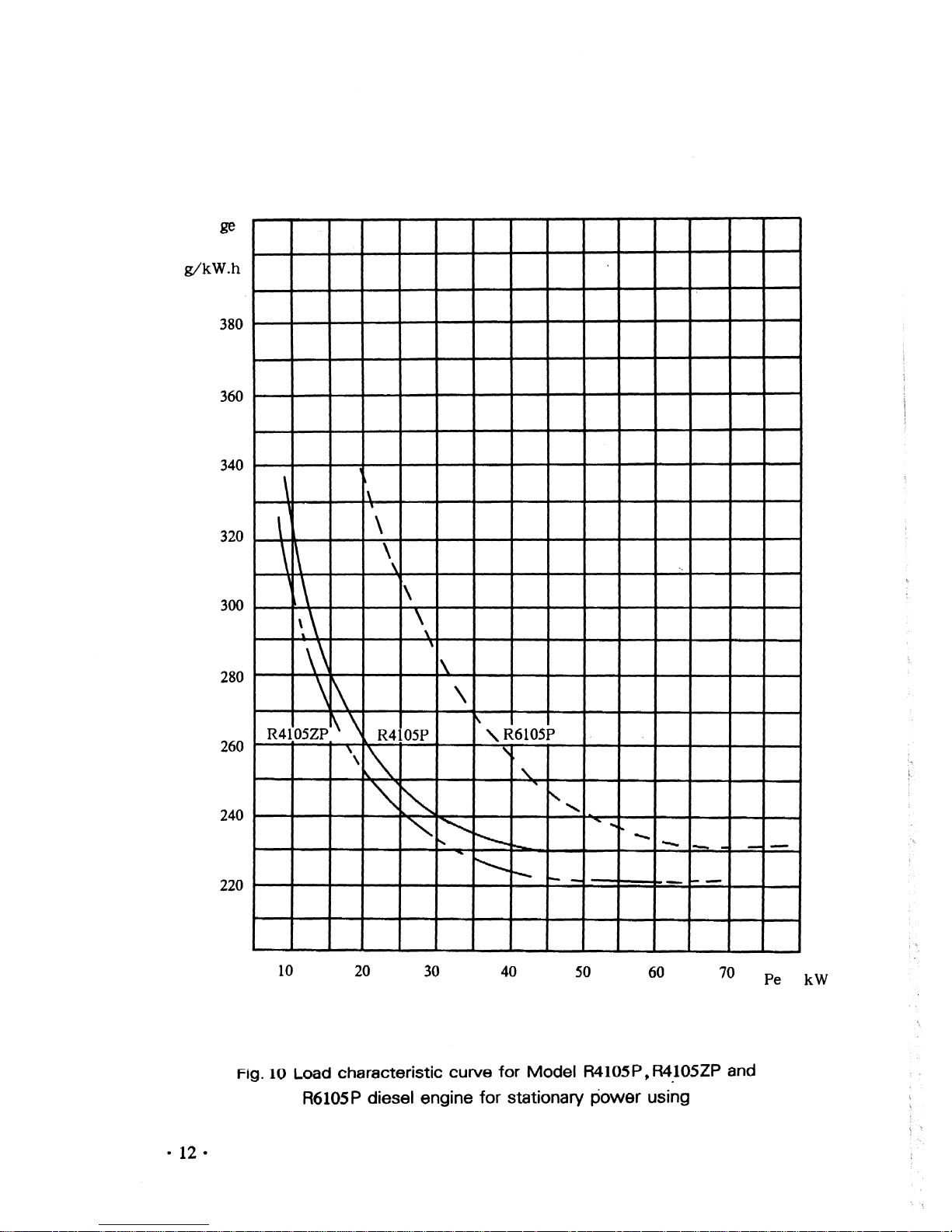
ge
g/kW.h
380
360
340
320
300
280
260
240
220
\
1\
\ 1
\
\~
\
\
'\
\
~\
\
\
\\
\
1\
\
\
\
R4105Zpi\ \
f\
R4105P
" R6105P
\
~
,
\
'"
'\
~
t'..
""-
'"
"'
"
...
~
......
,
1.0-
......
--
--
-
--
~
r-....
1--_
I-
10
20
30 40
50
60
70
Pe
kW
Fig.
10
Load
characteristic
curve
for
Model
R4105P,
R4.105ZP
and
R610SP
diesel engine for stationary power using
•12•

CHAPTER 1 Main Technical Specifications
and
DataofDiesel Engine
§ 1 Main Technical Specifications
No.
R4100Dl R4100D2
R4100ZD
Item
1
Type
Four
strokes,
Water
Cooling,Inline,Direct
injecting combustion chamber
2 Cylinder No.
-Bore
x
St~oke(
mm)
4-100x125
3
Total DisplacementofPiston(
L)
3.93
4
Pressure Ratio
17
:1
16:1
5 Firing Order
1-3--4-2
6
Air Intake
Mode
Naturally
Turbocharged
Aspirated
ISmin
OutpuVSpeed(
KW/r/min)
7
Rated Working
Ih
OutpuVSpeed(
KW/r/min)
Condition
!2H
Output/Speed(
KW/r/min)
3611500
42/1800 47/1500
8
Highest Idling Speed(
r/min)
~1575
~1890
~1575
9
Lowest
Idling Stable SPeed(
r/min)
e:;;600
10
Max
Torque/Speed(N...
m1r/min)
11
Average
Effective
Pressure(
Kpa)
733
712
951
-
12
Rated Working
Fuel
Consumption
Rate(glKW
*h)
~231
~224
-
13
Condition
Oil
Consumption
Rate(
glKw
*h)
~1.63
-
14
Exhaust
temperature(
OC)
Ei600
15
Crankshaft Ratating Direction
ounter
clockwise(
Facing
to
the
power
output
end)
16
Cooling
Mode
Forced
Water
Cooling
17
Lubricating
Mode
Compound
type
with
pressure and splash
tg
St~rting
Modo
I;loctri~
~t~rting
19
'
Net
Mass(
kg)
420
490
•13•
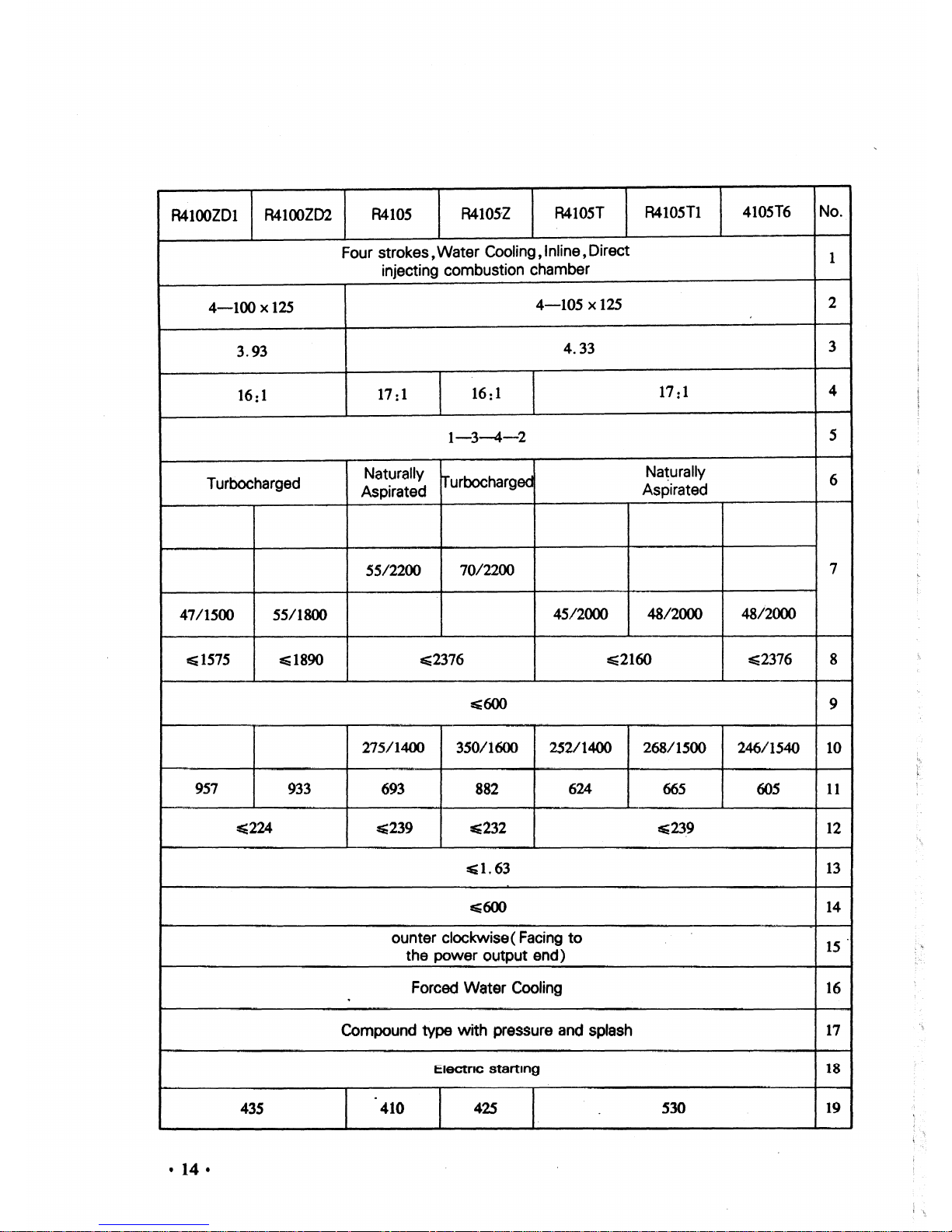
R4100ZDl
R4100ZD2
R410S
R410SZ
R410ST
R4105Tl
4105T6
No.
Four
strokes,
Water
Cooling,Inline,Direct
1
injecting combustion chamber
4-100x125
4-105x125
2
3.93
4.33
3
16:1
17
:1
16:1
17
:1
4
1-3--4-2
5
Turbocharged
Naturally
Irurbocharged
Na~urally
6
Aspirated
Aspirated
55/2200
70/2200
7
47/1500 55/1800
45/2000
48/2000
48/2000
~1575
E;1890
~2376
~2160
=5:2376
8
~600
9
275/1400
350/1600
252/1400
268/1500
246/1540
10
957
933
693
882
624
665
605
11
~224
~239
~232
~23.9
12
Etl.63
13
E;600
14
ounter clockwise( Facing
to
15
the power output end)
Forced
Water
Cooling
16
Compound
type
with
pressure and splash
17
ElectrIC
starting
18
435
410
425
S30
19
• 14 •
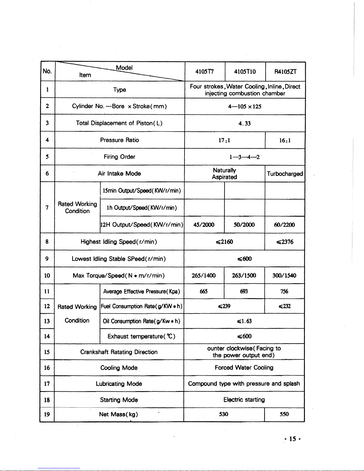
No.
4105T7
410STIO
R4105ZT
Item
1
Type
Four
strokes,
Water
Cooling,Inline,Direct
injecting
combustion
chamber
2
Cylinder No.
-Bore
x Stroke (
mm)
4-105
x 125
3 Total Displacement
of
Piston(
L)
4.33
4
Pressure Ratio
17
:1
16:1
5 Firing Order
1-3-4-2
6
Air Intake
Mode
Naturally
Turbocharged
Aspirated
15min
OutpuVSpeed( KW/r/min)
7
Rated Working
Ih
OutputiSpeed(KW/r/min)
Condition
12H
OutpuVSpeed(
KW/r/min)
4SI2000 50/2000 6012200
8
Highest Idling Speed(
r/min)
E;2160
:s=2376
9
Lowest
Idling Stable SPeed(
r/min)
~600
10
Max
Torque/Speed(
N *
mlr/min)
265/1400
26311500 300/1540
11
Average
Effective
Pressure(
Kpa)
66S
693
756
-
12
Rated Working
Fuel
Consumption
Rate
(gIKW• h)
=s;239
tti232
-
13
Condition
Oil
Consumption
Rate(
g/Kw.
h)
~1.63
-
14
Exhaust temperature (
ac
) Ei600
15
Crankshaft Ratating Direction
ounter
clockwise ( Facing
to
the
power
output
end)
16
Cooling Mode.
Forced
Water
Cooling
17
LUbr~cating
Mode
Compound
type
with
pressure and splash
18
Stal1ing
Mode
Electric starting
19
Net
Mass(
kg)
S30
550
..
•15•
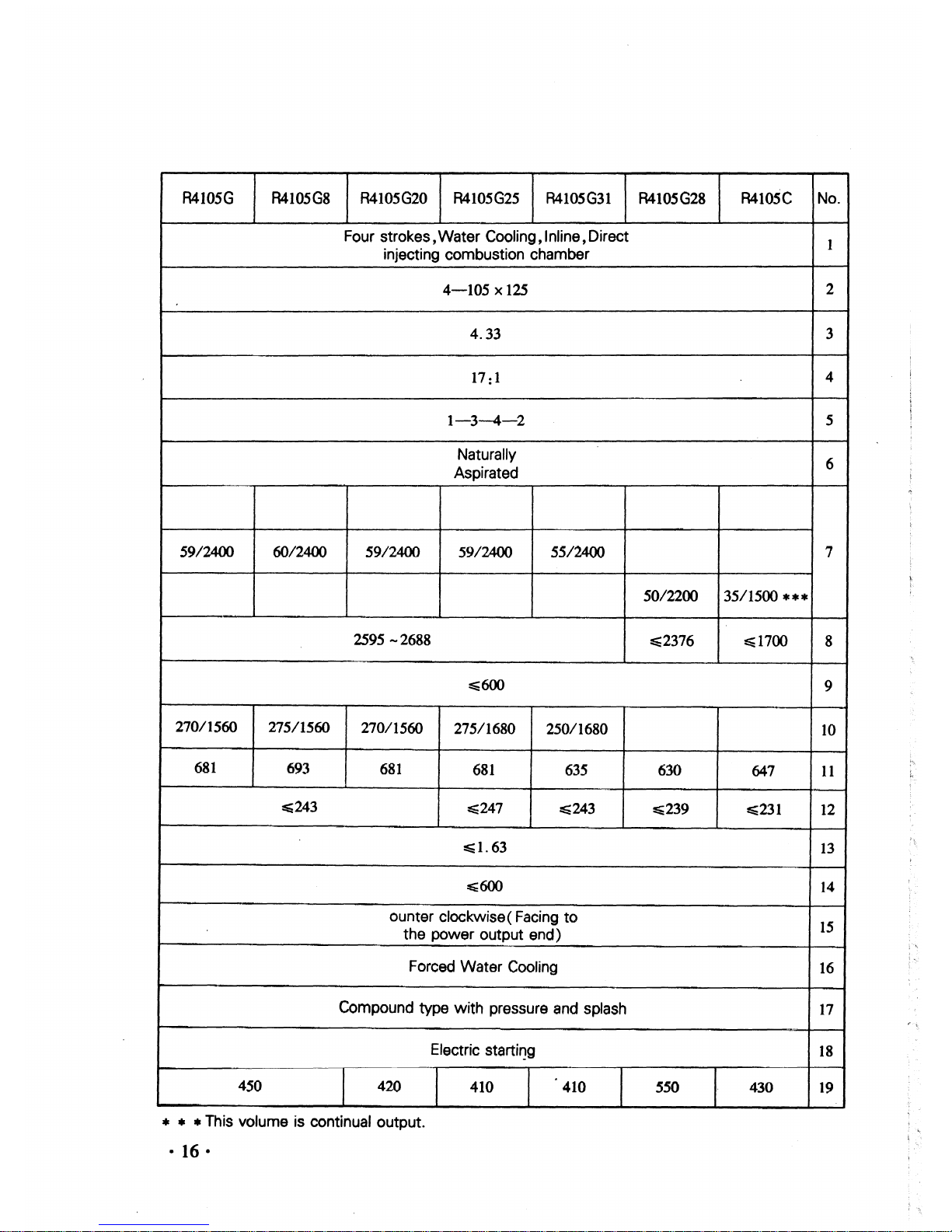
R4105G
R4105G8
R4105G20
R4105G25
R4105G31
R4105G28
R4105C
No.
Four
strokes,
Water
Cooling,Inline,Direct
1
injecting combustion chamber
4-105x125
2
4.33 3
17:1
4
1-3-4-2
5
Naturally
6
Aspirated
59/2400 60/2400 59/2400
59/2400 55/2400 7
50/2200
35/1500
***
2595
-2688
~2376
~1700
8
E;600
9
270/1560
275/1560
270/1560
275/1680
250/1680
10
681
693
681
681
635
630
647
11
~243
~247
E;243
~239
~231
12
:E:
1.63
13
~600
14
ounter clockwise ( Facing
to
15
the
power output
end)
Forced
Water
Cooling
16
Compound type
with
pressure and splash
17
Electric starti'1Q
18
450 420
410
410
550
430
19
• • • This
VOlume
is continual output.
•16•
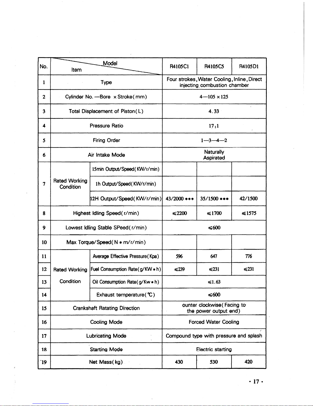
No.
R410SCI
R410SCS
R410SDI
Item
1
Type
Four strokes,Water Cooling,Inline,Direct
injecting.combustion chamber
2
Cylinder No.
-Bore
x Stroke(
mm)
4-105
x 125
3
Total DisplacementofPiston(
L)
4.33
4 Pressure Ratio
17
:1
S
Firing Order
1-3-4-2
6
Air Intake
Mode
Naturally
Aspirated
lSmin
OutputlSpeed( KW/r/min)
7
Rated Working
Ih Output/Speed( KW/r/min)
Condition
12H
Output/Speed(
KW/r/min)
43/2000
•••
35/1500
•••
42/1500
8
Highest Idling Speed(
r/min)
E;2200
E;;1700
E:1575
9
Lowest Idling Staljle SPeed(
r/min)
~600
10 Max Torque/Speed(N •
mlr/min)
11
Average
Effective
Pressure
(
Kpa
)
596
647
176
-
12
Rated Working
Fuel
Consumption
Rate
(gIKW
*h)
E;239
~23.
E:231
-
13
Condition
Oil
Consumption
Rate
(glKw*h)
~1.63
~
14
Exhaust temperature(
CC
)
E;600
15
Crankshaft Ratating Direction
ounter clockwise( Facing to'
the
power
ou~put
end)
16
Cooling
Mode
Forced Water Cooling
17
Lubricating
Mode
Compound
type
with
pressure and splash
18
StartinQ
Mode
Electric starting
·19
Net Mass(
kg)
430
'30
420
•
17
•
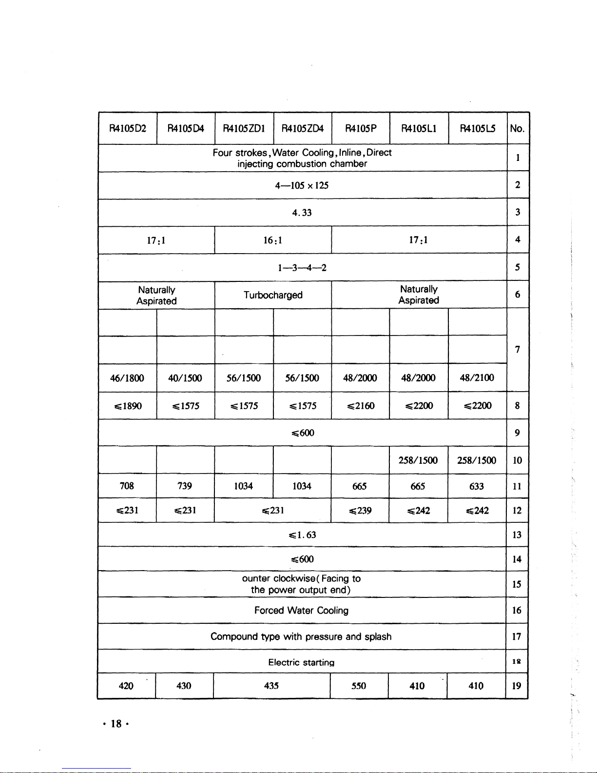
R4105D2
R410SD4
R410SZDl
R4105ZD4
R410SP
R4105Ll R410SL5
No.
Four strokes, Water Cooling, Inline,Direct
1
injecting combustion chamber
4-105x125
2
4.33
3
17:
1
16:
1
17 :1
4
1-3-4-2
5
Naturally
Turbocharged
Naturally
6
Aspirated
Aspirated
7
46/1800
40/1500
56/1500
56/1500
48/2000 48/2000
48/2100
Ei1890
~lS7S
~1575
~1575
E;2I60
~2200
E;2200
8
~600
9
258/1500
258/1500
10
708
739
1034 1034
665
665
633
II
~231 ~231
~231
~239
~242
E;242
12
~1.63
13
~600
14
ounter clockwise( Facing
to
15
the power output end)
Forced Water Cooling
16
Compound type
with
pressure and splash
17
Electric starting
tg
420
430
43.5
5.50
410 410
19
--
 Loading...