

Huafeitech HF-V10-10P8G2SF Hardware Installation Manual

- I -
HF-V10-10P8G2SF
Hardware Installation Manual
Beijing Huafei Technology Co.,Ltd.
Tel: 86-10-82894971
Fax: 86-10-82894971-8008
Email: market@huafeitech.com
Website: www.huafeitech.com.cn
Disclaimer: Information offered in this manual by Beijing Huafei Technology Co., Ltd
is intended to be as accurate as possible. However, there might be unintentional
errors, and we reserve the right to amend herein without notice.
All rights reserved
No any part of documentation is allowed to excerpt, reproduce, copy, translate without
the prior written permission by Beijing Huafei Technology Co., LTD.
Copyright © 2013 Beijing Huafei Technology Co., LTD

Table of Contents
- I -
Table of Contents
Chapter 1 Switch Overview......................................................................................................................................1
1.1 Standard Configuration...............................................................................................................................1
1.2 Characteristic Parameters of HF- ................................................................................................................2
Chapter 2 Installation Preparation............................................................................................................................. 4
2.1 Cautions...................................................................................................................................................4
2.2 Safety Advice............................................................................................................................................ 4
2.2.1 Safety Principles............................................................................................................................ 4
2.2.2 Safety Notices................................................................................................................................4
2.2.3 Safety Principles for Live Working.................................................................................................... 5
2.3 Requirements for Common Locations.......................................................................................................... 6
2.3.1 Environment.................................................................................................................................. 6
2.3.2 Location Configuration Prevention....................................................................................................6
2.3.3 Cabinet Configuration..................................................................................................................... 6
2.3.4 Power Requirements...................................................................................................................... 6
2.4 Installation Tools and Device.......................................................................................................................7
Chapter 3 Installing the HF-V10 Switch......................................................................................................................8
3.1 Installation Procedure of HF-V10.................................................................................................................8
3.2 Installing the Chassis of HF-V10................................................................................................................. 8
3.2.1 Installing the Chassis on the Desk....................................................................................................9
3.2.2 Installing the Chassis on the Cabinet................................................................................................ 9
3.3 Connecting the Port................................................................................................................................... 9
3.3.1 Connecting the Console Port........................................................................................................... 9
3.3.2 Connecting the SFP Optical Port .................................................................................................. 11
3.3.3 Connecting Ethernet Electric Port ................................................................................................. 12
3.4 Checkup After Installation ....................................................................................................................... 13
Chapter 4 HF-V10 Maintenance..............................................................................................................................14
4.1 Opening the Chassis .............................................................................................................................. 14
4.2 Closing Chassis ..................................................................................................................................... 15
Chapter 5 Hardware Fault Analysis..........................................................................................................................16
5.1 Fault Separation .................................................................................................................................... 16
5.1.1 Power Fault ................................................................................................................................ 16
5.1.2 Faults Relative with Port, Cable and Connection ............................................................................ 16
5.2 LED description ..................................................................................................................................... 16
HF-V10 Hardware Installation
- 1 -
Chapter 1 HF-V10 Switch Overview
The document describes the characteristics and parameters of HF-V10 and gives
an overview of HF-V10.
1.1 Standard Configuration
HF-V10 switch has 8 gigabit electric ports and 2 gigabit optical ports. See the
following table:
Table 1-1 Attributes of the necessary ports
Port
Features
gigabit electric port
UTP (RJ45) interface
gigabit optical port
SFP
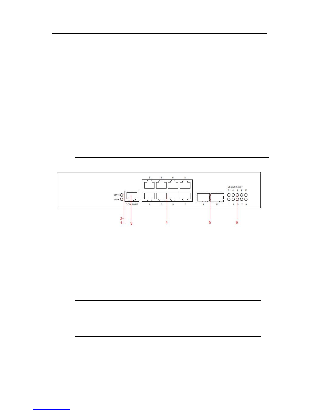
Figure 1-1 Front template of the HF-V10 switch
Table 1-2 Parts at the front template of the HF-V10 switch
No.
Abbrev.
Name
Remarks
1
PWR
Power LED
It is on when power source P2 provides
power normally.
2
SYS
System indicator
If the indicator flickers, the system works
normally.
3
Console
Console port
Manages the switch locally.
4GEgigabit electric port
UTP (RJ45) interface ,
10/100/1000BASE-T
5
SFP
gigabit optical port
Gigabit SFP optical port
6
LED
Link/ACT
LED indicator
When it is on, the corresponding port is
connected.
When it flickers, the corresponding port
is transmitting data.
HF-V10 Hardware Installation
- 2 -
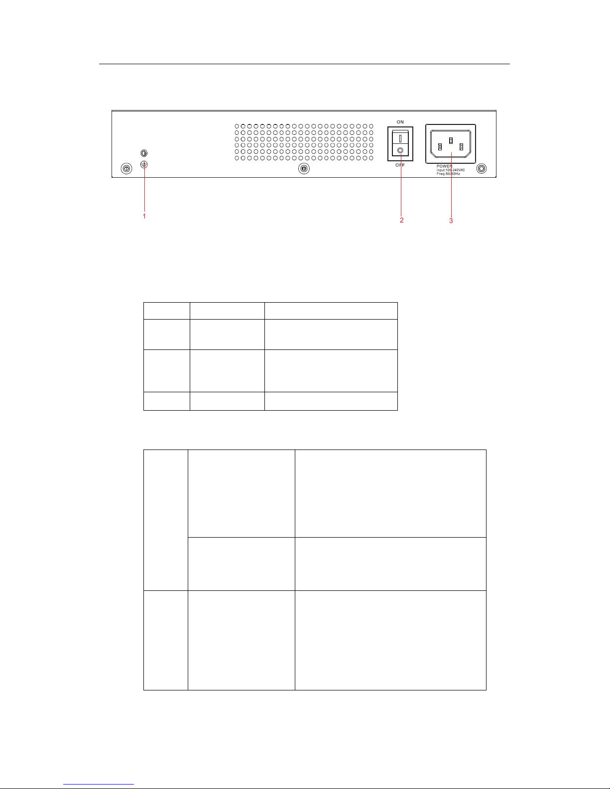
Figure 1-2 Back template of the HF-V10 switch
Table 1-2 Parts at the rear template of the HF-V10 switch
No.
Name
Remarks
1
Grounding
column
The grounding must be fine.
2
Power switch
ON means opening the power,
while OFF means cutting off the
power.
3
AC power socket
AC100-240V
1.2 Characteristic Parameters of HF-V10
Protocol
standard
Supported standard
IEEE 802.1d Spanning Tree Protocol
IEEE 802.1p Class of Service
IEEE 802.1q tagged VLAN
IEEE 802.3x Flow control
IEEE 802.3z asymmetric flow control
Network management
standard
RFC 1157 SNMP v1/v2
RFC 1213 MIB II
RFC 1757 RMON 1,2,3,9
Hardware
features
Memory
Flash Memory: 8M Bytes
DDR SDRAM: 64Mbytes
HF-V10 Hardware Installation
- 3 -
Standard configuration
8 10/100/1000 Base-Tx ports
2 gigabit optical ports
Specifications
240*150*42MM
Working
temperature/humidity
-10℃-45℃; 10%-85% no condensation
Storage temperature/
humidity
-40℃-85℃; 5%-95% no condensation
Power Source’s
Characteristics
Input voltage: AC100-240V
Input frequency: 47-63Hz
Input current: 1A/230V
Power consumption
Up to 13W

HF-V10 Hardware Installation
- 4 -
Chapter 2 Installation Preparation
2.1 Cautions
Similar to other electronic products, the semiconductor chip easily gets damaged if you
power on and off abruptly and frequently.To restart up the switch of HF-V10, you have
to open the power on-off three or five seconds after the power is cut off.
You shall not collide harshly with HF-V10 or fall it from a high place, which may
damage the internal hardware of the switch.
You should use correct outside ports to connect the switch of HF-V10.Do not insert
the Ethernet plug into the console port (RJ45 8-line socket). Similarly, do not insert
the console cable into the console port (RJ45 8-line socket).
Note:
1) When you plug or dial out the power line, keep the power line horizontal with the
power socket.
2) When the lifetime of our products ends, handle them according to national laws
and regulations, or send these products to our company for collective processing.
2.2 Safety Advice
2.2.1 Safety Principles
Keep dustless and clean during or after the installation.
Put the cover at the safe place.
Put tools at the right place where they are not easily falling down.
Put on relatively tight clothes, fasten the tie or scarf well and roll up the sleeve,
avoiding stumbling the chassis.
Put on the protective glasses if the environment may cause damage to your
eyes.
Avoid incorrect operations that may cause damage to human or devices.
2.2.2 Safety Notices
The safety notices mentioned here means that improper operation may lead to body
damage.
Read the installation guide carefully before you operate the system.
 Loading...