

HTW RSJ, RSJ-100/N1-540V-D, RSJ-200/SN1-540V-D, RSJ-380/SN1-820-D, VD Owners And Installation Manual
OWNER’S AND INSTALLATION
MANUAL
HEAT PUMP
Thanks for choossing our product.
Please, read carefully this manual
before using the product
ENGLISH
1H
HTW-RSJ420SZN1H
The water heater
NOTE
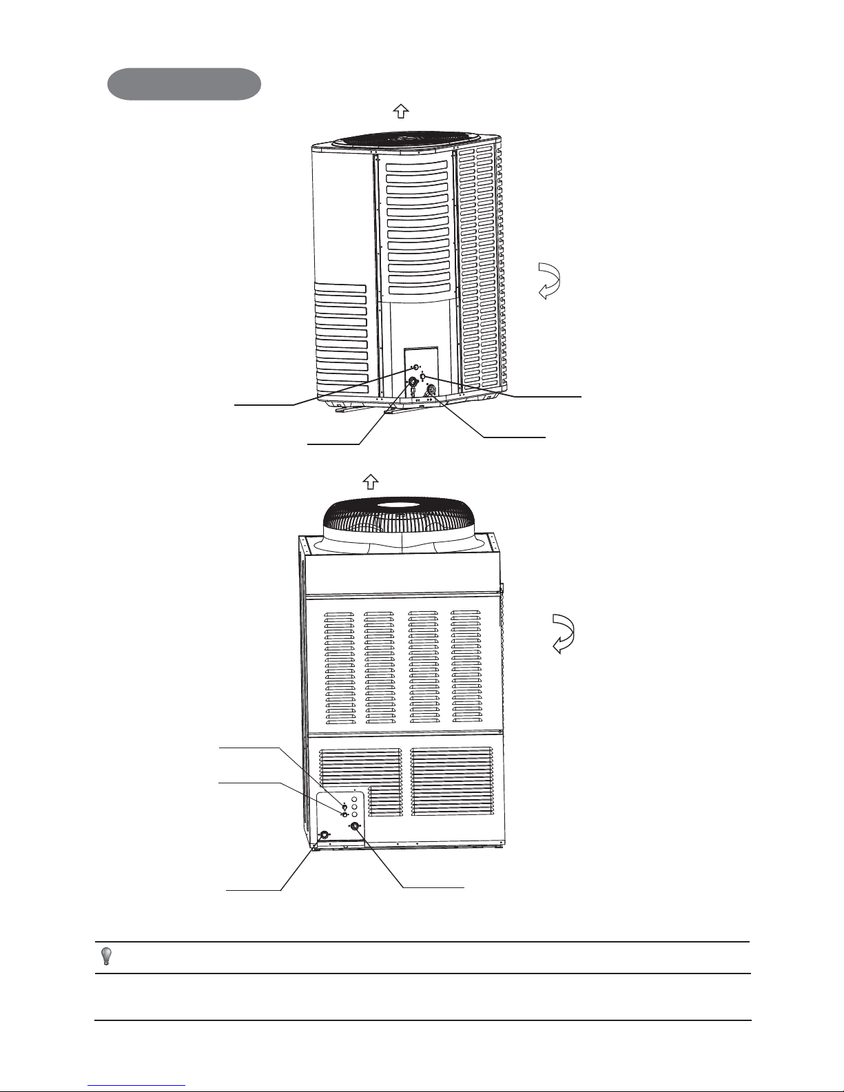
All the picture in this manual are for explanation purpose only. They may be slightly different from the unit you purchased (depand
on model).The actual shaped shall prevail.
Air inlet (3 faces)
Water inlet
& Scupper
Water outlet
& Scupper
RSJ-100/N1-540V-D
RSJ-200/SN1-540V-D
Air outlet
High-presure
Connector
Low-presure
Connector
Water inlet
& Scupper
Water outlet
& Scupper
Air inlet (front and back side)
RSJ-380/SN1-820-D
Air outlet
High-presure
Connector
Low-presure
Connector

1
Installation & Operation Manual
WARNING
Ask your dealer for installation of the water heater. Incomplete
installation performed by yourself may result in a water
leakage, electric shock, and fire.
Ask your dealer for improvement, repair, and
maintenance.
Incomplete improvement, repair, and maintenance may result
in water leakage, electric shock, and fire.
In order to avoid electric shock, fire or injury, or if you detect any
abnormality such as smell of fire, turn off the power supply and call
your dealer for instructions.
Never let the wire control get wet. It may cause electric shock
or a fire.
Never press the button of the wire control with a hard, pointed
object. The wire control may be damaged.
Never replace a fuse with that of wrong rated current or other
wires when a fuse blows out. Use of wrong wire or copper
wire may cause the unit to break down or cause a fire.
It is not good for your health to expose your body to the air
flow for a long time.
Do not insert fingers, rods or other objects into the air inlet or
outlet.When the fan is rotating at high speed, it will cause
injury.
Never use a flammable spray such as hair spray, lacquer
paint near the unit. It may cause a fire.
Never touch the air outlet while the swing flap is in operation.
Fingers may become caught or the unit may break down.
Never put any objects into the air inlet or outlet.Objects
touching the fan at high speed can be dangerous.
Never inspect or service the unit by yourself. Ask a qualified
service person to perform this work.
Do not dispose this product as unsorted municipal waste.
Collection of such waste separately for special treatment is
necessary.
CONTENTS PAGE
ACCESSORIES............................................................................
IMPORTANT SAFETY INFORMATION.......................................
SELECTING THE INSTALLATION LOCATION...........................
IMPORTANT ITEMS FOR INSPECTING INSTALLATION OF
THE UNIT......................................................................................
PIPES CONNECTION OF THE UNIT...........................................
ELECTRIC CONNECTION OF THE UNIT...................................
INSTALLING OPTIONAL FITTINGS OF THE UNIT ...................
SPECIFICATIONS & PARAMETERS OF THE UNIT..................
OPERATION AND PERFORMANCE OF WATER-HEATER......
TRIAL RUN..................................................................................
TROUBLESHOOT OF ABNORMAL PHENOMENA .................
1
1
2
2
4
5
8
9
10
14
15
1. ACCESSORIES
Table 1-1
Model˖
KJR-16B/E
Control units
and display
units status
For pipeline
connection
Water tank
temperature
inspection
Wire control
assembly
Unit
Qty.
3XUSRVH
6KDSH
Installation
& Operation
Manual
Water Tank
Temperature
sensor
Y-shaped
filter
WARNING
Failure to observe a warning may result in death.
CAUTION
Failure to observe a caution may result in injury
to the equipment.
The safty precautions listed here are divided into two categories.
In either case, important safty information is listed which must be
read carefully.
2. IMPORTANT SAFETY INFORMATION
To prevent injury to the user or other people and property
damage, the following instructions must be followed. Incorrect
operation due to ignoring of instructions may cause harm or
damage.
CAUTION
The instruction shall state the substance of the
following:
This appliance is not intended for use by persons(including
children)with reduced physical,sensory or mentalcapbilities,or
lack of experience and knowledge,unless they have been
given supervision or instruction concerning use of the
appliance by a penson responsible for their safety.
Children should be supervised to ensure that they do not play
withe appliance.Do not use the water heater for other
purposes. In order to avoid any quality deterioration, do not
use the unit for cooling precision instruments, food, plants,
animals or works of art.
Before cleaning, be sure to stop the operation, turn the
breaker off or pull out the supply cord. Otherwise, an electric
shock and injury may result. In order to avoid electric shock
or fire, make sure that an earth leak detector is installed.
Be sure the water heater is grounded. In order to avoid
electric shock, make sure that the unit is grounded and that
the earth wire is not connected to gas or water pipe, lightning
Heat Pump Heating
Water Unit
!!
!
!
RSJ-100/N1-540V-D
RSJ-200/SN1-540V-D
RSJ-380/SN1-820-D
Heat Pump Heating
Water Unit
!
!
!
!
2
Installation & Operation Manual
3.1 Precautions before installation:
Decide the correct way of conveying the quipment.
Try to transport this equipment with the original package.
If the unit needs to be installed on a metal part of the building,
electric insulation must be perforned, and the installation must meet
the relevant technical standards of electric devices.
4. IMPORTANT ITEMS FOR INSPECTING
INSTALLATION OF THE UNIT
3. SELECTING THE INSTALLATION
LOCATION
Enough space of installation and maintenance is available.
The air inlet and outlet are free from obstacles and strong wind.
The bearing surface is level and can bear weight of the unit, and
is suitable for installing the unit horizontally without increasing
noise or vibration.
The operation noise and the expelling of air do not affect
neighbours.
No flammable gas is leaked.
It is convenient for piping and wiring.
CAUTION
Installing the equipment in any of the following places may lead to
faults of the equipment (if that is inevitable, please consult the
dealer):
Ɣ The site contains mineral oils such as cutting lubricant.
Ɣ Seaside where the air contain much salt.
Ɣ Hotspring area where corrosive gases exist, e.g., sulfide gas.
Ɣ Factories where the supply voltage fluctuates seriously.
Ɣ Inside a car or cabin.
Ɣ Place like kitchen where oil permeates.
Ɣ Place where strong electromagnetic waves exist.
Ɣ Place where flammable gases or materials exist.
Ɣ Place where acid or alkali gases evaporate.
Ɣ Other special environments.
4.1 Installation
Confirm the model, serial number and name to avoid mistaken
installation.
4.2 Electric wiring
Select the power supply capacity and wire size according to
the Design Manual. The size of the power cable of the unit should
be greater than that of ordinary motors.
Check the subscriber grounding is effective.
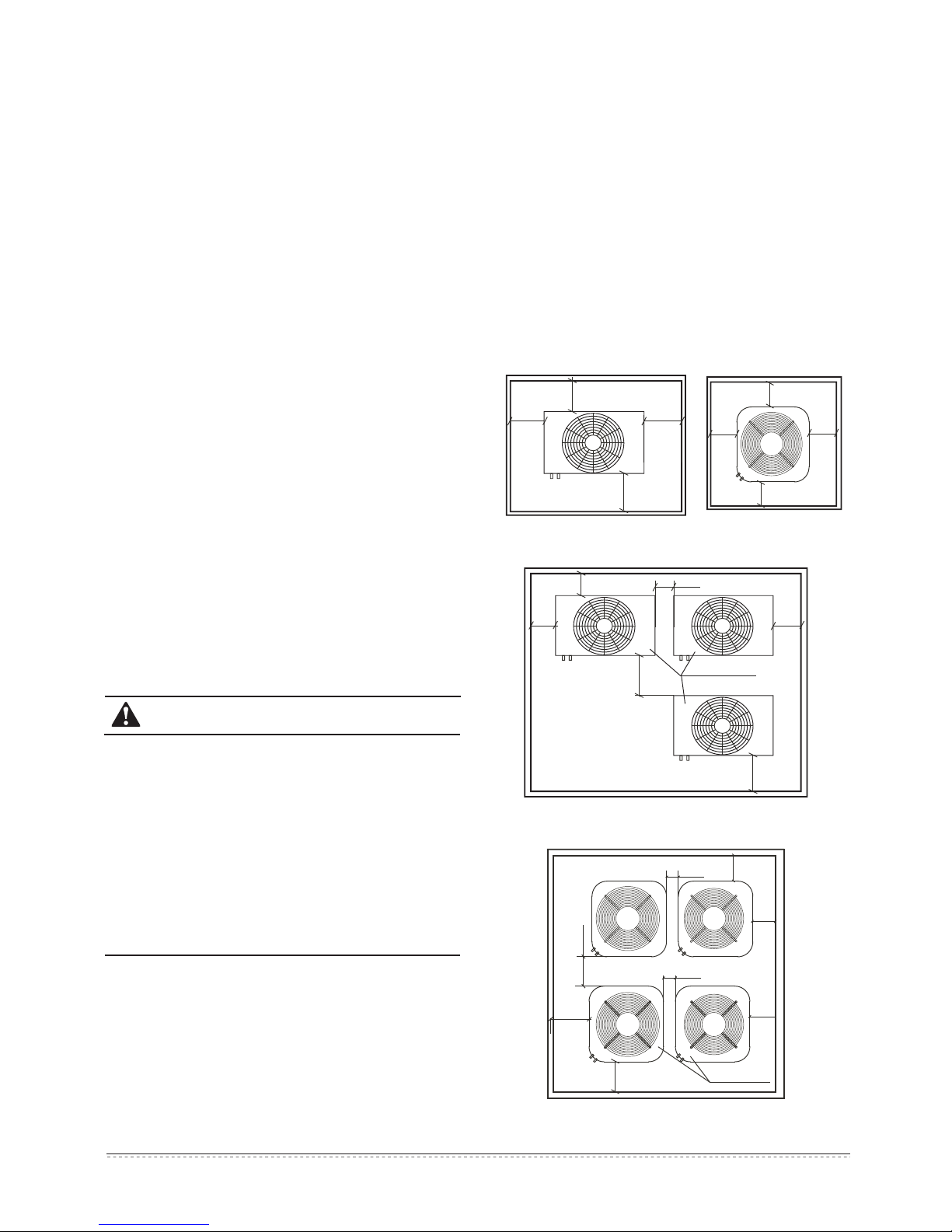
4.3 Installation space
Before installing the unit, reserve the space of maintenance
shown in the following figure.
Ensure enough space for installation and miantenance.(unit:mm)
Heat Pump Heating
Water Unit
!
!
!
!
!
!
RSJ-100/N1-540V-D
RSJ-200/SN1-540V-D
RSJ-380/SN1-820-D
Heat Pump Heating
Water Unit
!
!
!
!
!
!
!
!
conductor or telephone earth wire.
In order to avoid injury, do not remove the fan guard of the outdoor
unit.
Do not operate the heater pump with a wet hand. An electric shock
may happen.
Do not touch the heat exchanger fins. These fins are sharp and
could result in cutting injuries.
After a long use, check the unit stand and fitting for damage.
If damaged, the unit may fall and result in injury.
To avoid oxygen deficiency, ventilate the room sufficiently if
equipment with burner is used together with the unit.
Arrange the drain hose to ensure smooth drainage.
Incomplete drainage may cause wetting of the building, furniture etc.
Never touch the internal parts of the controller.
Do not remove the front panel. Some parts inside are dangerous to
touch, and a machine trouble may happen.
Never expose little children, plants or animals directly to the air flow.
Adverse influence to little children, animals and plants may result.
Fig.4-1
1
2
3
Installation & Operation Manual
Table 4-1
0
Static Pressure
(Pa)
Model
4618 5929
10342
RSJ-100/N1-540V-D
High
Fan Speed
(m3/h)
Low
Fan Speed
(m
3
/h)
High
Fan Speed
(m
3
/h)
Low
Fan Speed
(m
3
/h)
High
Fan Speed
(m3/h)
Low
Fan Speed
(m3/h)
RSJ-200/SN1-540V-D RSJ-380/SN1-820-D
6237 6994
10
3591
5156
9667
5479
6485
12396
11843
20
2378
4357
8963
4774
5994
11309
25
1400 3377 8247
4368 5380
10828
4.4 Carrying the unit onto the installing site
Use 4 steel ropes of F6mm or more to hoist the unit and convey it into the room.
In order to avoid scratch or deform the unit surface, apply guard boards to the contacting surface.
After move onto installing site, please comfirm the main unit are placed in horizontal.
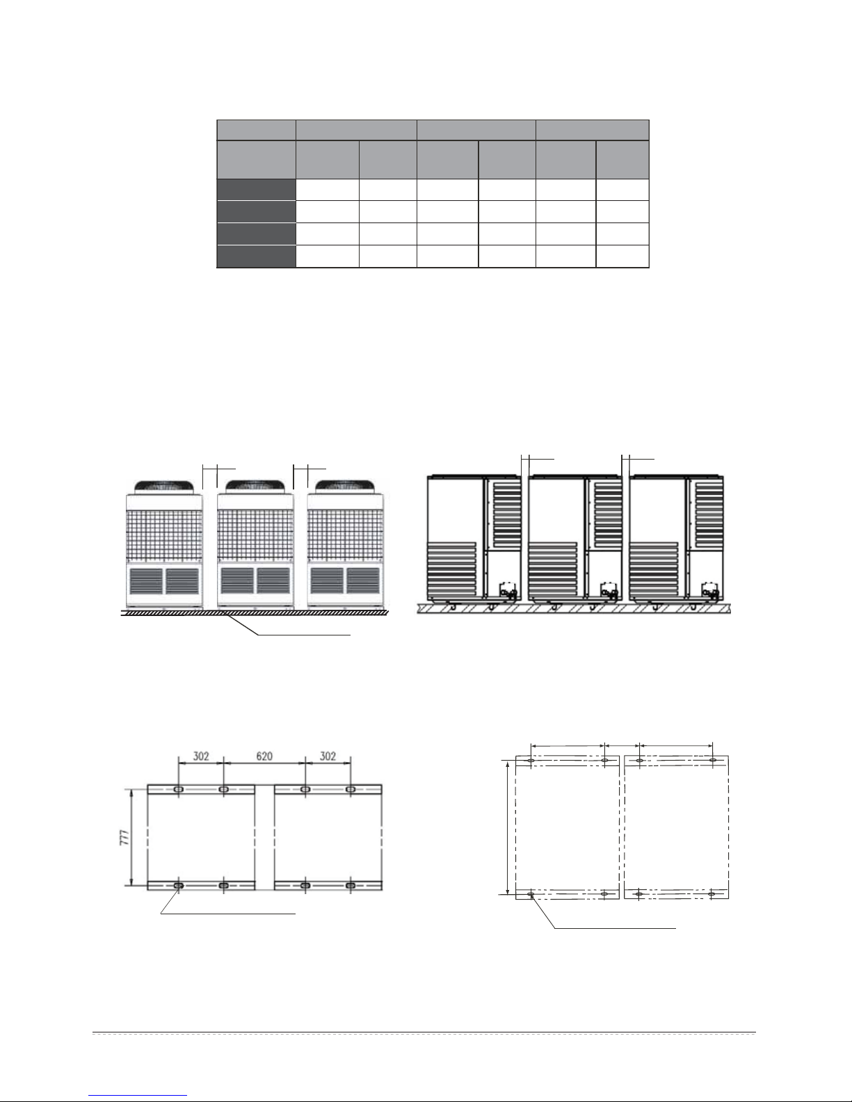
4.5 Installing multiple units
As shown in the figure, leave spacing of at least 400mm between units.
If the unit installed in a underground chamber, an indoor room or other hermetic place, please pay attention to where surrounding air, as well
as which air exhust and air circulating system.
Fig.4-2
RSJ-380/SN1-820-D
RSJ-100/N1-540V-D
RSJ-200/SN1-540V-D
M12 ground screw
4 screws for each unit
!PP !PP
!PP !PP
The distance of the foundation bolt is shown in the following figure.
RSJ-100/N1-540V-D
RSJ-200/SN1-540V-D
Through hole
(15×20 rectangular hole)
RSJ-380/SN1-820-D
Fig.4-3
Through hole
(15×20 rectangular hole)
682
855
740
682
10HP
10HP
4
Installation & Operation Manual
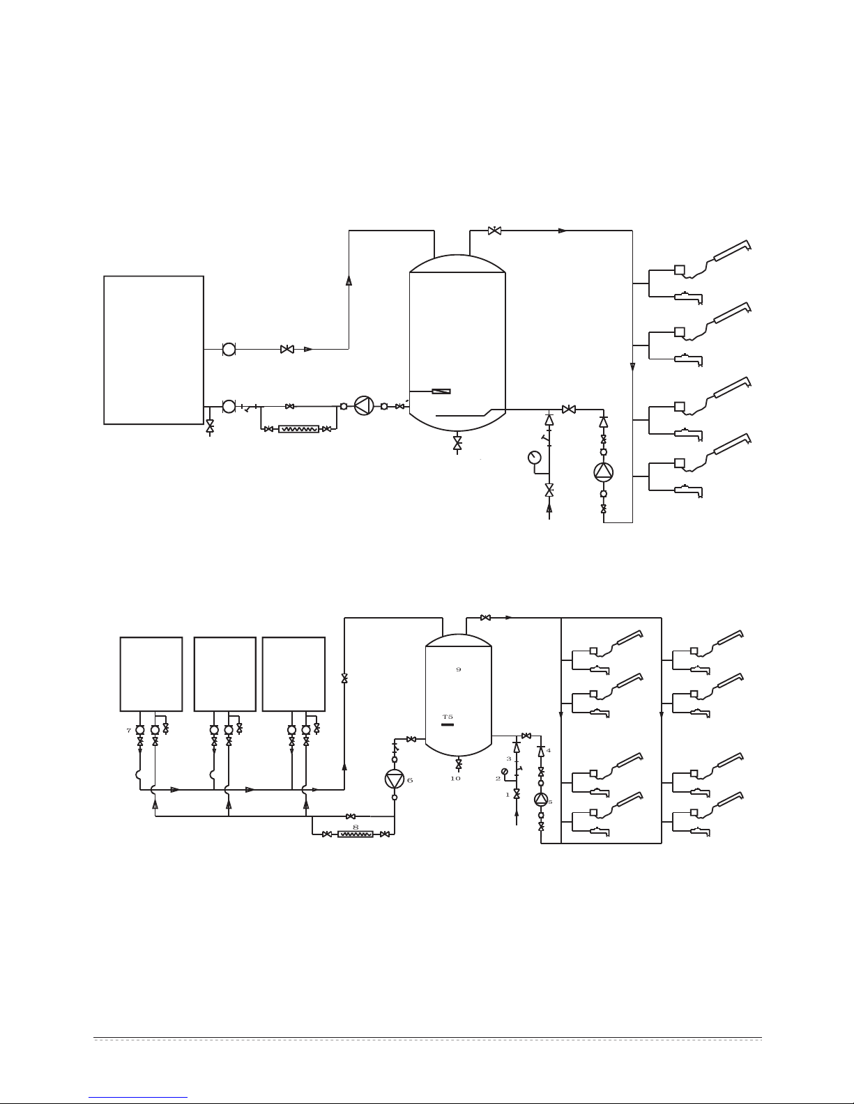
Fig.5-1
Single connected for RSJ-100/N1-540V-DǃRSJ-200/SN1-540V-DǃRSJ-380/SN1-820-D
Multiple connected for RSJ-100/N1-540V-DǃRSJ-200/SN1-540V-DǃRSJ-380/SN1-820-D
Fig.5-2
5.PIPES CONNECTION OF THE UNIT
1.Valve
2.Manomete
3.Filter
4.One way valve
5.Return pump
T5.Tank sensor
6.Pump
7.Joint
8.Auxiliary heater(optional to the user)
9.Water Tank
10.Cleaning valve of the water tank
Heat Pump
Heating Water
Unit
water
outlet
water
outlet
Valve
joint
joint
Tap water
Manometer
Cleansing
valve
Pump
T5
sensor
Auxiliary
heater(optional)
To drain
ditch
water
inlet
water
inlet
Filter
Filter
Return
pump
Valve
Water tank
One way
Valve
Hot water outlet Hot water inlet
Sent to the user
Heat pump
heating
water 0#
unit
Heat pump
heating
water 1#
unit
Heat pump
heating
water 15#
unit
inlet
outlet
To drain ditch
Hot water inlet
Hot water outlet
Sent to the user
Tap water
Water
outlet
Water
inlet
A maximum of 16 heat pump heating water units can be connected in parallel
During install connective pipe, you must beware that do not let
any dust or other foreign substance intrude into pipe system.
Water inlet and outlet pipes could be installed as long as the
water-heater have been fixed.
5.1 Thermal insulation
Thermal insulation materials should be employed to seal up water
outlet and inlet pipes.
5.2 Schematic diagram of single and multiple
connected water heater systems
 Loading...