

HTS HRP 30 C 2, HRP 60 C 2, HRP 40 C 2, HRP 80 C 2 Installation And Maintenance Manual

SEPT 2001 INSTALLATION AND MAINTENANCE
Visit us on the web at w
www.htseng.com
w w

Model Nomenclature
HRP = High Rise Heat Pump - Vertical WSHP Ch assis
HRP 30 C 2
Voltage
Unit Size
Unit Size Cfm
30 420
40 478
60 602
80 807
Note: Installation and maintenance are to be performed only by qualified personnel who are
familiar with local code and regulations, and are experienced with the type of equipment.
2= 208/60/1
Design
Vintage
Transportation and Storage
Upon receipt of the equipment, check cartons and pallets for visible damage. Note any
such damage on the shipper's delivery ticket before signing it. If there is any evidence of rough
handling, immediately open the cartons to check for concealed damage. If any damage is found,
notify the carrier within 48 hours to establish your claim and request their inspection and report.
Our Warranty Claims Department should then be contacted.
All cartons are marked with "UP" arrows and should be transported and stored in their
upright position. If it is necessary to place air conditioning units in other than their upright position
for on-site transfer, the units must be placed in their normal upright position for at least 24 hours
before attempting to start them.
Temporary storage at the job site must be indoors, completely sheltered from rain, snow,
etc. High or low temperatures naturally associate d with weather patterns will not harm the
conditioners. Excessively high temperatures [140°F (60°C)] may deteriorate certain plastics and
cause permanent damage.

Installation
General
1. To prevent damage this equipment should not be operated for supplementary heating and
cooling during the construction period.
2. Inspect the cartons and pallets for any specific tagging numbers indicated by HTS Engineering
per a request from the installing contractor. At this time the voltage, phase and capacity should
be checked against the plans.
3. Check tagging numbers against the plans to ensure unit installation in the correct location.
4. The installing contractor will find it beneficial to confer with piping, sheet metal, ceiling and
electrical foremen, together, before installing any conditioners.
Chassis
It is recommended that a piece of rubber or neoprene pad material, 112" (13mm)
maximum thickness, be placed under the unit cabinet.
Remove chassis from its carton. Remove compressor hold-down bolts from bottom of
chassis.
Connect electrical quick connect plug to matching receptacle on the cabinet mounted
control box.
Slide the chassis into the cabinet until the outside flanges are flush with the front. Install the
coil blockoff panel
Return Air Door
Screw architectural acoustical front panel to the dry wall furring as per detail in shop drawings.

START UP : FLUSHING THE SYSTEM
1. Prior to first operation of any HRP unit, the water circulating system must be cleaned and flushed of all
construction dirt and debris. The chassis cannot be connected to system when flushing is being
conducted. Supply and return pipes must be interconnected with factory supplied hoses to properly
flush system. This will prevent the introduction of dirt into the chasis.
2. Fill system at city water makeup connection with all air vents open. After filling close all air vents
assure that boiler and heat rejector are off but flow is allowed through each. The installer/contractor
should start main circulating pump with pressure reducing makeup valve open. Check vents in sequence
to bleed off any trapped air, assuring circulation through all components of the system.
3. Shut off circulating pump and open all drains and vents to completely drain the system. Short circuited
supply and return runouts should now be connected to the HRP unit with factory supplied supply and
return hoses. Teflon tape is recommended over pipe dope for pipe thread connections. Use no sealers at
the swivel flare connections of hoses.
4. Trisodium phosphate is recommended as a cleaning agent during flushing. However, many localities
prohibit the introduction of phosphates into their sewage systems. The current recommendation is to
contact your local water treatment specialist.
5. Refill the system with clean water. Test with litmus paper for acidity, and treat as required to leave the
water slightly alkaline (pH 7.5 to 8.5). The specified percentage of antifreeze may also be added at this
time. Use commercial grade antifreeze designed for HVAC systems only. Do not use automotive grade
antifreeze.
6. Installing contractor to provide written confirmation that the system was properly flushed and balanced.
An independent flushing & balancing agency must be used. Once this is complete a proper start can be
completed by HRP start-up contractor.
7. Set the system heat add setpoint to 70°F (27°C) and the heat rejection setpoint to 85°F (29°C). Supply
power to all motors and start the circulating pumps. After full flow has been established through all
components including the heat rejector (regardless of season) and air vented and loop temperatures
stabilized, each of the HRP units will be ready for check, test and start-up and for air and water
balancing.
8. FAILURE TO PERFORM ANY OF THE ABOVE STEPS WILL RESULT IN
TERMINATION OF MANUFACTURES WARRANTY.

START UP : AFTER FLUSHING
1. Open all valves to full open position and turn on power to the conditioner.
2. Set thermostat for FAN ONLY operation by selecting OFF at the system switch and ON at the fan
switch. If AUTO fan operation were selected, the fan would cycle with the compressor. Check for proper
air delivery.
3. Set thermostat to COOL. If the thermostat is an automatic changeover type, simply set the cooling
temperature to the coolest position. On manual changeover types additionally select COOL at the system
switch. Again, many conditioners have time delays which protect the compressor against short cycling.
After a few minutes of operation, check the discharge grilles for cool air delivery. Measure the temperature
difference between entering and leaving water. It should be approximately 1 1/2 times greater than the
heating mode temperature difference. For example, if the cooling temperature difference is 15 degrees, the
heating temperature difference should have been at ten degrees. Without automatic flow control valves,
target a cooling temperature difference of 10° to 14°F (5° to 8°C). Adjust the combination shutoff/balancing
valve in the return line to a water flow rate which will result in the 10° to 14° (5° to 8°C) difference.
4. Set thermostat to HEAT. If thermostat is the automatic changeover type, set system switch to the
AUTO position and depress the heat setting to the warmest selection. Some conditioners have built-in time
delays which prevent the compressor from immediately starting. With most control schemes, the fan will
start immediately. After a few minutes of compressor operation, check for warm air delivery at discharge
grille. If this is a "cold building" start-up, leave unit running until return air to the unit is at least 65°F
(18°C). Measure the temperature difference between entering and leaving air and entering and leaving
water. With entering water of 60° to 80°F (16° to 27°C), leaving water should be 6° to 12°F (3.3° to 6.6°C)
cooler, and the air temperature rise through the machine should not exceed 35°F (19°C). If the air
temperature rise exceeds 35°F (19°C), then the water flow rate is probably inadequate. If the water
temperature difference is less than 6 degrees, the water flow rate is excessive. If the water temperature
difference exceeds 12°F (6.6°C), then the water flow rate is inadequate.
5. Check the elevation and cleanliness of the condensate line. If the air is too dry for sufficient
dehumidification, slowly pour enough water into the condensate pan to ensure proper drainage.
6. If the conditioner does not operate, check the following points:
a. Is supply voltage to the machine compatible?
b. Is thermostat type appropriate?
c. Is thermostat wiring correct?
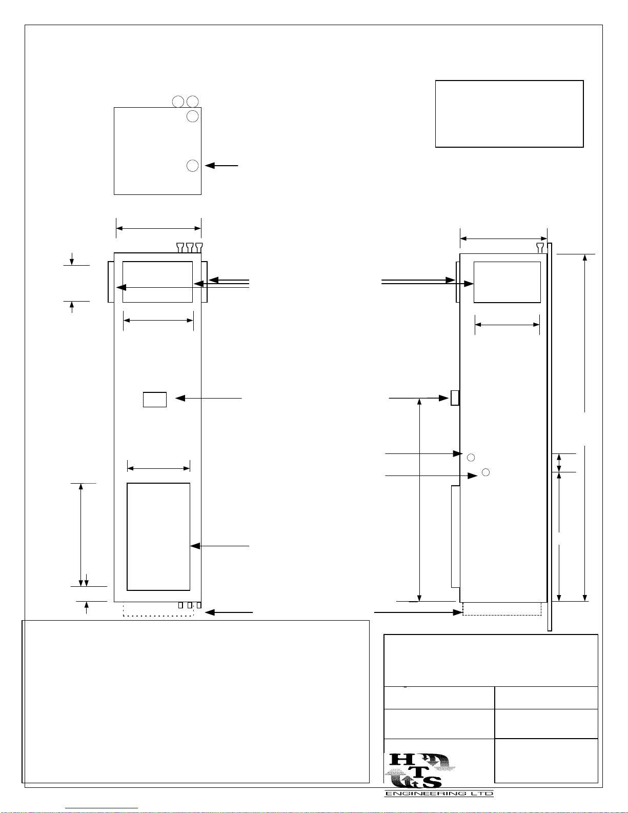
DIMENSIONAL DATA: HRP 30 & 40
8" - HRP 30
10"- HRP 40
16
14
S R
TAG: HRP 30 -
C
P
Optional Top Power Knockout
Supply Air Openings
1/2" Flange
TAG: HRP 40 -
18.5
14
Themostat Junction Box
14
36
5
Side Power Knockout
Remote Thermostat Wiring
Knockout
Return Air Opening
Optional 5" legs
NOTES:
Temporary riser supports provided, contractor to supply riser clamps to
-
support risers in multistory applications.
- Return Air Opening is on the front of the unit, Rear Right Hand Unit shown.
60
Project:
Engineer:
82-96 *
5
40
Contractor:
- Unit Includes hose kits and shut off valves.
- Risers are made with type M copper, expanded connections are provided.
- Contractor to provided couples where piping not swagged.
- Optional 2 x 8 Outside Air Opening Available.
Date:
Drawing Number:
101
Revision:
Sept 2001
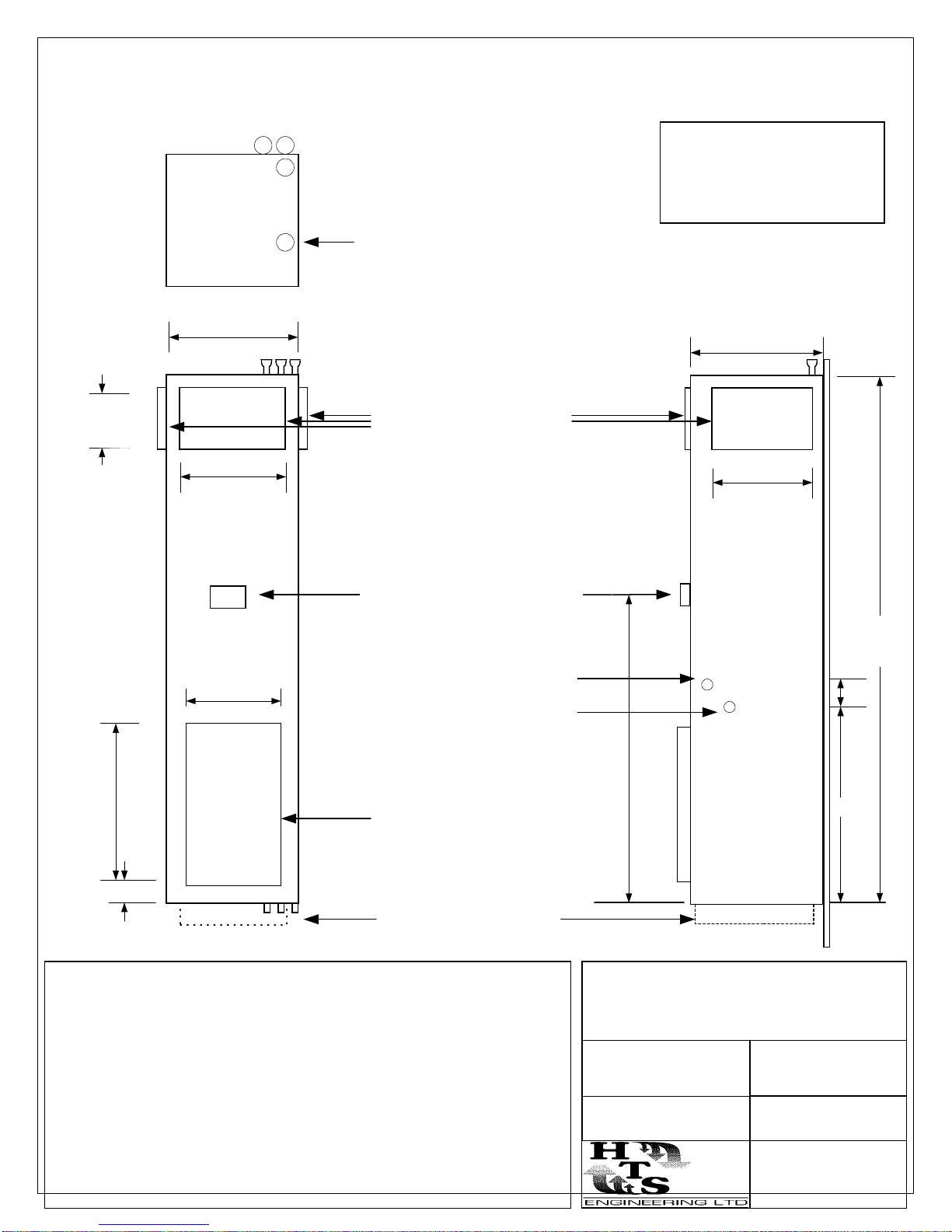
DIMENSIONAL DATA: HRP 60 & 80
12" HRP 60
14" HRP 80
18
16
S R
TAG: HRP 60 -
C
TAG: HRP 80 -
P
Optional Top Power Knockout
21.5
Supply Air Openings
1/2" Flange
16
Themostat Junction Box
16
38
5
Side Power Knockout
Remote Thermostat Wiring
Knockout
Return Air Opening
Optional 5" legs
NOTES:
Temporary riser supports provided, contractor to supply riser clamps to
-
support risers in multistory applications.
82-96 *
5
60
40
Project:
- Return Air Opening is on the front of the unit, Rear Right Hand Unit shown.
- Unit Includes hose kits and shut off valves.
- Risers are made with type M copper, expanded connections are provided.
- Contractor to provided couples where piping not swagged.
- Optional 2 x 8 Outside Air Opening Available.
Engineer:
Date:
Contractor:
Drawing Number:
102
Revision:
Sept 2001
 Loading...