

HTS C5 User Manual

C5
User Manual
April 5, 2009

CC5
5
User Manual page 2
Table of Contents
1. PURPOSE & SCOPE 5
2. REFERENCED DOCUMENTS 5
3. OVERVIEW 6
3.1. PRODUCT DESCRIPTION ..................................................................................... 6
3.2. TYPICAL INSTALLATIONS ..................................................................................... 7
3.2.1. Access Control Mode 7
3.2.2. Monitoring Mode 9
3.3.
CC5
5
VERSUS SEELANE ......................................................................................... 9
4.
CC5
5
MAJOR ELEMENTS 10
4.1. BLOCK DIAGRAM .............................................................................................. 10
4.2. MODES ............................................................................................................ 11
4.3. HARDWARE ..................................................................................................... 11
4.4. SOFTWARE ...................................................................................................... 12
4.4.1. General 12
4.4.2. Files loaded into CC55
unit 12
4.4.3 Windows based applications (loaded into the PC/Laptop) 12
4.5. SOFTWARE INTEGRATION IN A NETWORK........................................................... 13
5. IP CONFIGURATION 14
5.1. OVERVIEW ....................................................................................................... 14
5.2. NETWORK PROPERTIES .................................................................................... 14
5.3. ADVANCE USER NETWORK SETTING .................................................................. 15
6. WEB-SERVER 16
6.1. OVERVIEW ....................................................................................................... 16
6.2. GETTING STARTED ........................................................................................... 16
6.3. MAIN MENU ..................................................................................................... 17
6.4. HOME PAGE .................................................................................................... 17
6.5. IMAGE PAGE .................................................................................................... 18
6.5.1. Procedure 18
6.5.2. Problems of images display 18
6.6. CONFIGURATION PAGE ..................................................................................... 20
6.6.1. General 20
6.6.2. Access Control 21
6.6.3. Monitoring 21
6.6.4. Local Camera 22
6.6.5. Remote Camera 22
6.6.6. Motion detection 23
6.6.7. RS-232 24
6.6.8. Net Client 25
6.7. CARS LIST MANAGEMENT PAGE ........................................................................ 25
6.7.1. Add Member 26
6.7.2. Edit Member 27
6.7.3. Remove Member 27
6.8. LPR LOG PAGE................................................................................................ 28
6.9. STATUS PAGE .................................................................................................. 28
6.10. SET CLOCK PAGE ............................................................................................ 29
6.11. EVENT LOG PAGE ........................................................................................... 29

CC5
5
User Manual page 3
6.12. LIVE PAGE ....................................................................................................... 30
7. ACCESSORIES 31
7.1. WINSCP.EXE .................................................................................................... 31
7.2. PUTTY.EXE ...................................................................................................... 32
8. SOFTWARE UPDATE 34
8.1. OVERVIEW ....................................................................................................... 34
9. SUPPORT AND MORE INFORMATION 35

CC5
5
User Manual page 4
I. DOCUMENT REVISION HISTORY:
DATE
BY
CHANGES
SECTIONS
APPROVED
Mar 5, 2009
Yossi Eliyahu
New document,
based on C4
All
Preliminary
Mar 17, 2009
Yoram Hofman
Logo, diagram
I, 4.1
Preliminary
April 5, 2009
Sherri Cizin
Formatting
All

CC5
5
User Manual page 5
1.Purpose & Scope
This document provides general information on Compact Camera-Based Car Controller (CC55
),
a stand-alone vehicle access-control system. This document is intended for system users and
provides all the information required operating the system.
The CC55
is the next generation version of the C
44
system, with more powerful on-board
computer and additional functionalities.
2. Referenced Documents
2.1 CC55
Installation & Maintenance (for system installers).
2.2 SeeData (HTS publication) – for networking information.
2.3 SeeLane – recognition system based on PC. (HTS product)
These documents are available in our home page, see last section for details.
CC5
5
User Manual page 6
3. Overview
3.1.Product Description
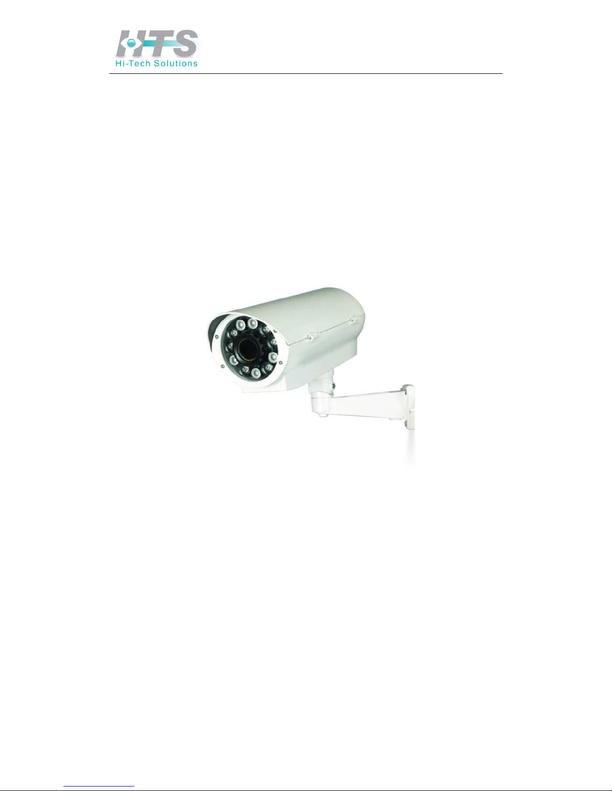
CC5
5
is a highly integrated computer/camera/illumination unit that performs all of the functions
of a LPR system with its embedded microprocessor and SeeCar recognition package. CC55
is a
versatile stand-alone unit that can be used for either access control in parking installations or
as a license plate sensor to report license plate numbers.
The CC55
unit identifies the license plate number, compares it with the vehicle database, and
can automatically open a gate for authorized vehicles. The system can also be used in traffic
surveillance and monitoring applications where passing vehicles can be tracked, while
automatically generating a vehicle list.
For applications involving multiple LPR points, several individual CC55
units can be networked
together to a single server. Authorized vehicle numbers are stored on the unit’s database,
while pre-registered users can access and modify it, via the internal web server interface
using a network (LAN) or Internet connection. The CC55
can transmit the recognized plate
number to other systems via TCP/IP over the LAN or optional wireless.
The unit triggers either by an internal software trigger based on motion detection, or by an
external trigger such as a loop detector. It can be easily installed at the entrance to a secured
area or parking lot, requiring only a power supply, and (optionally) a gate.

CC5
5
User Manual page 7
3.2.Typical installations
3.2.1.Access Control Mode
The following figure illustrates how the system is typically installed at the entrance of a
secured area. A sensor (such as a loop detector) indicates the presence of the car, which
signals the CC55
unit (behind the gate's boom) to start a new recognition sequence. The unit
identifies the car, and if authorized – it opens the gate.
Figure 3.2: a typical access-control installation
For most secured areas the system can control the entrance only, while the exit will be
automatically opened for the vehicles exiting the secured area (by a direct connection from
the sensor to the gate).
CC5
5
User Manual page 8
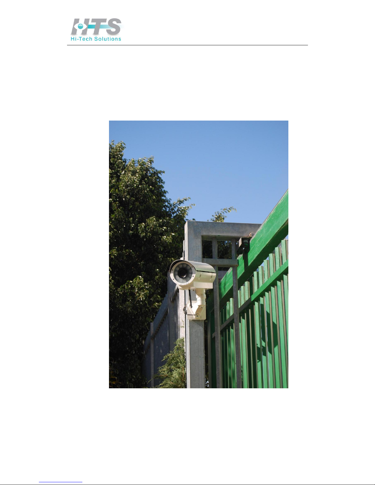
The following photo shows a sample installation in a secured office area. This unit operates
with an internal software trigger (motion detection) and opens the barrier for vehicles that
match its "white list". It sends the recognition results by either wired TCP/IP connection or via
its wireless antenna.
Note that the enclosure and bracket of this unit may change in future due to updates in its
design.
Photo 3.2a: Secured office installation

CC5
5
User Manual page 9
3.2.2.Monitoring Mode
The unit may be used to simply report on the passing vehicles.
This unit can be connected to other units via a local network (“intranet”) that reports the
recognition results, including the captured image, to a central server. The transmission can be
done by wireless or wired TCP/IP.
3.3.CC55
versus SeeLane
Our product line also includes powerful Windows PC-based solution – such as SeeLane. If
a multiple-lane access control is required, we recommend installing the SeeLane system
instead - which controls more lanes and has additional functions.
Please consult with us on the optimum solution for your needs.
CC5
5
User Manual page 10
4. CC55
Major Elements
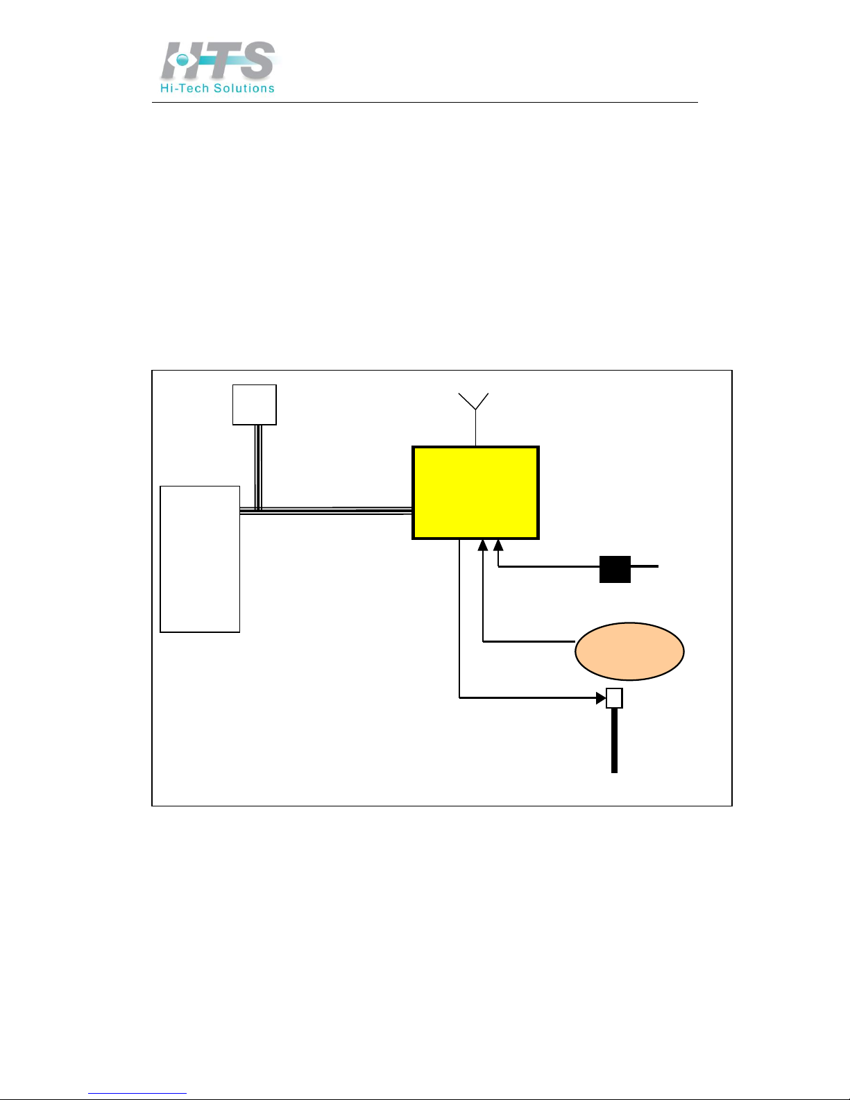
4.1. Block Diagram
The CC55
access-control system architecture is illustrated in the following diagram. The
peripherals on the left side are connected by a network connection.
On the right side the inputs are power supply (a DC adapter connected to the mains), and an
optional sensor (dry-contact indicating vehicle presence, such as a loop detector). The unit's
internal motion detection can be used instead of the external trigger.
The optional output is the gate relay open signal, which can be used to open the gate for
authorized vehicles.
Camera &
LPR unit
Power Supply
Optional
Sensor
Optional
Gate
110-220
TCP I/P
Wireless
Modem
Optional
Server
Antenna

CC5
5
User Manual page 11
4.2. Modes
The CC55
can operate in two modes:
Access Control - the unit opens a gate for an authorized vehicle (listed in a local
database). It can also optionally send the result via the network, using SeeData which
should be installed on the server.
Monitoring Mode - the unit just reports the recognized number via the network using
SeeData.
The selection of the mode is by a configuration parameter. It is pre-configured at the factory
(according to the order specification) and may be changed later by using the intranet/network
site of CC55
or by PC/Laptop application.
4.3. Hardware
1. CC55
--
illumination/camera/LPR unit.
2. Power supply for CC55
(a special 15 VDC, 110-220VAC power supply is used which
was qualified to operate with the SCH unit).
3. Vehicle detector (sensor). A standard dry-contact sensor, such as loop detector.
4. PC Host - any standard PC/laptop, connected by network communications, used for
normal operation (as an option to update the main application or the members list, or
receive the results) or used for the installation and maintenance.
5. Gate - the CC55
output relay controls the gate's relay to open the gate for the authorized
vehicle (required for the access control mode only).
 Loading...