

HTP America 200-AC-DC Owner’s Manual
IJTP^-,,,**
lnvertig
Owner's
Manual
200
ACIDC
America,
HTP
1.8OO.USA-WELD.
lnc.
.
Nordic
3200
847-357-0700
.
Road
Arlington
.
FAX: 847-357-0744
Heights,
lL 60005-4729
www.usaweld'com
'
I
NI anufacturer's
gr
HTP
against
agreed
expressly
It is
Dcaler.
Warrantv
HTPAmerica,
rvorkmanship
Agrerica,
Anterica,
HTp
satisfaction
expressed
a,,ihorize,
rvarran{
This
senice
reiiabiliry,
LITP America,
breach
w'arranN
of
under
will
Inc.
to have
implied,
or
any other
departments
nor
rvarranty
of
specifying
HTp America,
products at
This
purchase.
any
rvarranry'is
\Yarran
America,
Inc.
ty
there are
that
Inc.
delective
materials
warrants each
normal
repair and
with transponation
Inc.
thus
been
all other
and
person
not apply
shall
in any
has been subjected
r.vhich
Inc. shall
not be
within not more
the claimed defect.
Inc. has
reserved
without incurring
time
void unlcss
no warranties,
products or
on
or
nerv
use and
service
replace,
defective.
obligations
to assume
welding
to any
way so as
liable in any
than 30
the right
rvarranry card
expressed
parts fumished
workmanship
welding machine
for three
at its factory,
charges
This
for it any
the
in
to misuse,
to make
any obligation
any
prepaid and
warranty being
liabilities
or
other
machine
judgment
negligence
unless
event,
days after
change
to HTPAmerica,
is
sent
or
hereunder,
as follows:
free
to be
years after
part
or
which
expressly
on
liabiliry
has been
rvhich
HTPAmerica,
of
HTP America,
discovery,
the
in design
to install
from
delivery
thereof,
made
except
defects
to the original
implied,
parts
its examination
in lieu ofall
part
and
its
in connection
repaired
Inc.
accident.
or
Inc. receives
actual or
or add
on equipment
same
w'ithin
Inc.
by either
the
the Salesman,
Manufacturer's
in material
and
purchaser. HTP
products
neither assumes
it
with the
to affect
to be
shall
other
sale
or altered
its stabiliry
disclose
warranties,
of its
by unauthorized
notice of
construction
any improvements
l5 Lievs
trom dlte
retumed
to its
nor
machines.
and
alleged
alleged
to its
to
breach
oi
Note:
Warrantl':
Exclusions
to
l. ThcTigWelciingTorchiswarrantedforapcriodolninery(90)De-vsagainstdeiectsrnmaterial
rvorkmanship.
and
\\'T{iCFi CARRY
2. Thc
NO
rungstcn,
collet,
\\ARRANTY:
colietboCl-.
ceramic
nozzles
consumabie
are
iten-rs.
'il
Safety
Elcctric
harmful
lightrveight
br:rn
are
ignite.
trousers, and
helmet
precautions will
and
.
.
.
.
.
Suggestions
*,elding
arc
to skin and
clothing,
the skin and
not oily or
Wear a heavy,
*,ith a number
hot material.
To avoid
tloors. Concrete
Do not
they
Provide adequate
Do not
materials unless POSITIVE
Thesc materials
Do not
op.rations. Chlorinated
the
Ii
during
indication that
r,,eid
frre, do
weld
have been
rveld
',veld
ultra-violet
y'ou
develop
rvelding, stop
until
produces
eyes.
reflect from light colored surfaces,
eyes.
greasy.
pocket-less,
high-topped
eight or
protect
not weld on
masonry floors are safest.
or
on drums,
cleared as described
ventilation in the welding area at all
galvanized
on
produce toxic fumes.
in areas close
ra,vs and form
momentary eye,
ventilation is not adequate. Do
ventilation is improved.
ultra-violet rays,
Ultra-violet
Wear flameproof
The oit or
grease
long sleeve shirt,
work shoes.
darker lens and a cap.
hair, face, and skin from
e-ves,
wood,
barrels,
tanks
radiation
Wear
plastic
rvhich are
can
rvelding gloves rvhich
gloves
the
on
a full-face
tile, or carpeted
or other
containers until
inAWS Standard,4.6.0l.
zinc, cadmium or
sufficient
to degreasing
hydrocarbon
highly toxic
nose
vapors
or
lead beryllium
ventilation is
or spraying
may
phosgene gas.
throat irritrtion
welding immediately. This is an
not
penetrate
and
may
cuffless
welding
These
arc rays
times.
provided.
r'r'ith
react
continue
For more information,
cornply
I ANSI Standard
CUTTING,
2051 NW 7th St..
2. ANSI Standard
OCCUPATION
PROTECTION,
Standards
3. America
CUTTING
COMBUSTIBLES,
4. NFPA STANDARD
FOR
National Fire
Boston,
5 NFPA Standard
PROCIESSES. obtainable same
6 CG.{
CO\lPRESSED
the Compr.-sseC
Ne* \'ork. N\'
7.
to
OSHA
CUTTTi..iG
as applicable.
249 1 SAFETY
obtainable lrom
287.I SAFE
AND EDUCATIONAL
Instirute, 1430
Welding
CONTAINERS
\IELDING
Protection
lvIA 02210.
PA\{PHLET
10016
Standrrd
AND
to the follorving
refer
IN
the American
N{iami. FL 33 125.
standards and
WELDING
\\'elding
.\ND
PRACTICE FOR
EYE AND
obtainable
Sociery Standard A6.0
from
American
Broadway, New York, NY
National
WELDING
WHICH HAVE HELD
obtainable
51. OXYGEN.FIJEL
same as item l.
GAS
SYSTENIS
AND CUTTIIJG. obtainable from the
Assoc., 470 Atlantic Avenrre.
lB CUTTING AND
5
P-1
SAFE
GASES
Gas Association. 500
29 CFR, Part
IN CYLL|'JDERS, obtarn:rble tiom
1910,
WELDING
-1.
as item
HANDLING OF
Filth
Avenue.
Subpart
Q
WELDNC.
BRAZING.
Societl.
FACE
100 18.
AND
.
Exposed, electrically
w'eiding
the
can tatall.v shock
Do not stand. sit,
,.r'e1cling.
Fr.-qlienih inspect cabi:s for
"
R:pilcc
f -.ssi'cii
circuit, or
thos;
l:th:rl shock
hot conductors or other bare
a person
1ie, lean on or
lvith
exce ssivel.'
tiom b,rr:11 cablc.
metal in
ungrounded electricall.v hot equipment
rvhose
body becomcs a
touch
w
ear, cracks, anil drmrce.
u'orn
*'et
a
insulrrtior,
surfice
1,,-.
conductor.
*'hen
.t
r'''oi"i
Electrical Connection
\bur Invertig
power
shipped
jiailrl',\'-gieen
2C0 ACIDC operate s on single-phrse l,lll
[(*'-
15',r) 195.5
to 25+.i r"oitsl. The rnr,:i',:n-- rs n-r
i,ith a clug. Th;
qrrL:iri.
w
i:: is
ir; nct 1er,:s.
.,,ii'
I::ir":t
Lroir':l
rn:
l:..:',.,:,'r Ii-.t.:t-
l: 100 rmp:.
eiectrical air:-,:..iii:i.rs
-\ii
::;cliicirn in
iccal cocles r.i.,c.
lc;.-.i-J:L:'.:c
iidrn.inc.ii.
inS,Lll pc\.\ li
--,liri
hl'
rLri lh: bii:: :lltri :i.r'.i i'.
a::-'r.:t.
sl:r-r'-i:.i t.'i,r!'ri.iin.d
r.,rllt tltl
).t:litlr.rl
Fl-'-,r'lr.il
.'.'ir::,
-l
.t.
"
'.,'..
. :... ,.._-
r'. l:l::.rir.l,-.1
,.
rrti,r
r
oll
Ti:
i.j:
.'r,..:
-lr.:
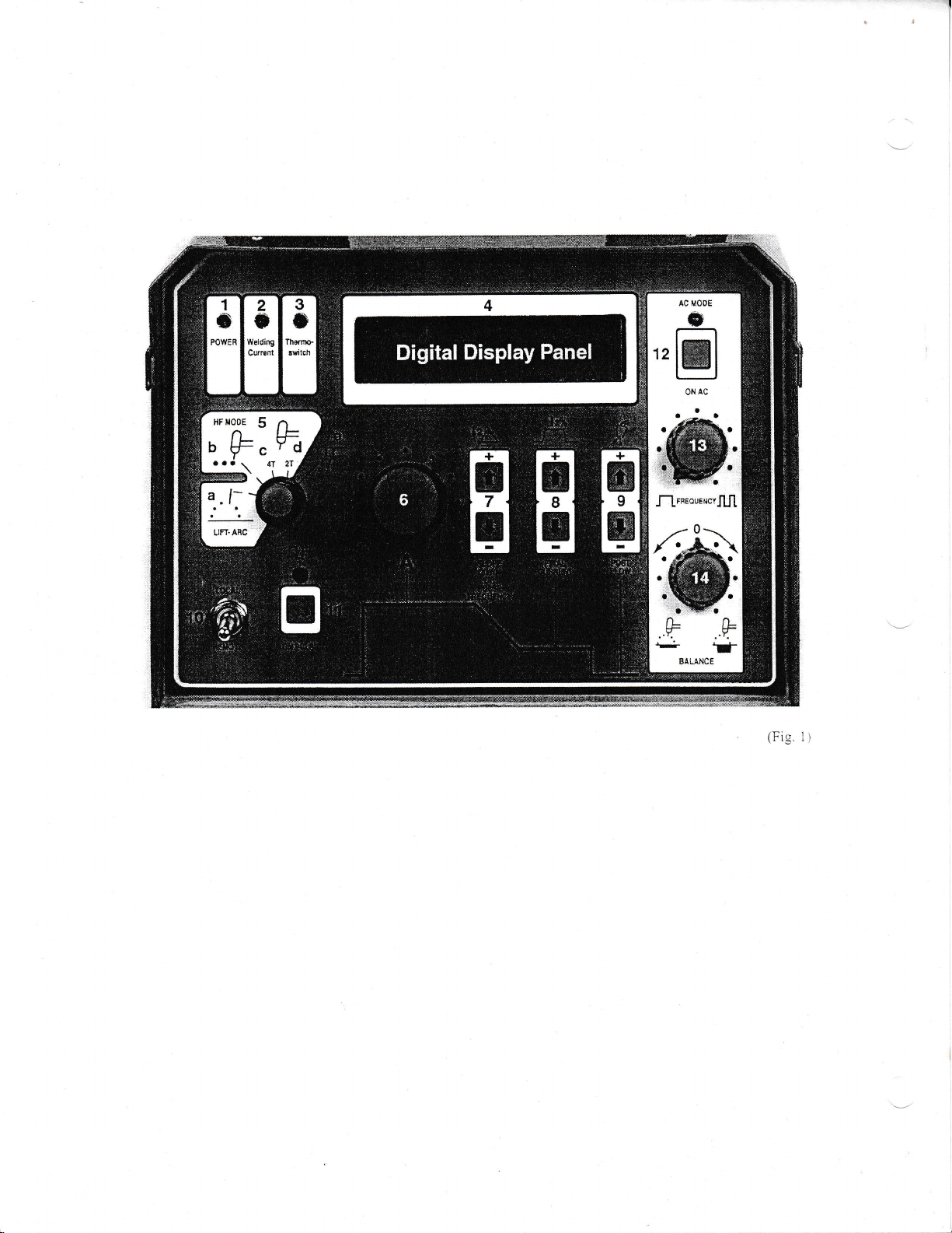
(Fig.
1)

Front Panel
(See
Fig.
Controls
1)
l) Porver Indicator
illuminated
lamp rs
This
your
Invertig
the unit is correctlv
2) Welding Current
When either
torch is depressed,
welding
torch and
illuminated.
your Invertig
If
rvelding
3)
The
c,vcle
current
Thermosrvitch
thermoswitch
your Invertig
of
this Iamp is
because
the machine
piugged in and tumed
Ailow
dorvn.
thcrmoswitch
be ready'to
-l)
Digital
The Digital
parameters are.
amperage.
rvclding cmperf,gc.
rcrur!
you
When
in the AC
Frequency and
thc AC
\\'hen the machine
press either
drsplay'rvilL
rirgitrl
s:conds
and the Post
\\'hcn the nachir.re
e ither
ir:-is
ti-.e Post Flou. Button
Do*'n
Slopc
pcrcint olbase
\\'hen the machine
the
press
de
*'i11 drsplay
is rurned
200
foot
the
welding current
the
200 AC/DC
indicator
Indicator
indicator
illuminated,
the machine
should
weld.
Display
Display
For example,
you
As
press
the "AC on" button
Weiding N{ode,
tile T2 button
rhe Tl button
Time
cunent.
"On
Pulse"
pulse frequency in hertz
the
Lamp
when the
On-Off
to the I or
or
to 220
LamP
trigger
the
connected
Indicator
pedal
Welding Current
the
is in
will be illuminated
lamp
LamP
lamp will light up
200 AC/DC
the machine
has overheated.
the cooling fans can
on so
to cool for l5
automatically and
reset
Panel
Panel allows
depress
the AC balance.
is in the 2T
displa.v
gas
flo"v
the'1T
is in
you
normal
the
the foot
the digital displa;"'panel
rvelding mode
(#7)
the
or
the Slope Do*n
in
seconiis.
w'clding mcCe
(=7), thc
(;9)
the
digitai
(T2)
in seconds,
the Post
and
in the Pulse
is
button
Welding N{ode and
(#1
switch on
position,
"On"
volt
will
power,
AC
on
switch
be applied
Indicator
stick-welding
when the dury
has
been
exceeded.
will no longer
the machine
Leave
to
minutes,
30
your Invertig
to see
'"vhat
display
pedal,
,vou
"vill
(#12)
rvhen the machine
(5d),
F|:rv Button
Post
Tirne
(5c).
Finai Currenr
will
display
the Final Current
in seconds.
Florv
Gas
1) the digital
display
(cycles per
the back of
indicating
the TIG
to the
will be
Lamp
the
mode,
the time.
all
When
weld
the unit
cool
the
your rvelding
r,r,'elding
the
is
the
see
rvill
displ:i
and vou
(=9
(T2)
in
anrl
.v''or-r
(;:ir.
Button
the
display
(i2)
you
panel
second).
in
*i11
I
tir:
\1'elding
5)
The
Invertig 200 AC/DC.
A)
B) Spot
CJ
is
D
t
l:
E) )rc
6) Amperage
This knob
.vour
amperage
lccaL,remote
lVlode Srvitch
welding mode switch
LiJtArc Mode-
w'elding arc
environment
interference
computers.
aluminum
or
for both AC
TIG Weld
To
tungsten
depress
with the
contact
this method for
able
being
lVelding
weld
for between
automaticali)-
performing a series
*'ere
Tcr seiect
i.r s;lcct
Ccrrn
..iT
no,le
\\'e
sugeest
*hich
is
trigger on
y'ou release the
When
you
depress
rvill
arc
['hen
using
rveld rvithout ha.,
:o
c:t
no\\'
..
is not sugg"'sr:ci
Ir
notj:
)T
Invertig
our
l
r:ieesed..
o..rf,tion
ll'eLding
electrode
operate.
the
without
r,vhere the
with
sensitive
good
A
repair
and DC
using
workpiece, activate
to the
the foot
pedal
work, the arc
Stick
to vary
tlode
stop.
the spot
a time bcnveen
This is Iike a
-
using
mounted on
the torch,
the trigger again
extinguish.
the h:rnd amperxge controi.
ancrtt-'
\\-irh th* i,:rch
-
2C0
unit
the
ri'ith the tl:ot
this
-
rvill alwa';s be
Adjustment
determines
can be adiusted
Invertig
200
is displa,ved
srvitch
the welding mode of
selects
lift arc mode aliorvs
you
high frequency. This is
high frequency arc
of this
components or
rvould be
Lift Arc mode
electrical
example
in hospitals. The
welding.
the Lift Arc Mode, simply
the torch trigger or
lift ofi
and
welding
your
amperage
the
spot
-
0.1 and 10 seconds
rvould
This
of repetitive
w'elding time, adjust
When
rvill
start.
rvith
the added benefit
with the foot
welding mode allow s
and then
good
be a
tack
thc T2
0.lsec and 10.0 sec.
lock
this mode'"vith
the torch.
your Invertig 200
trigger, it
inq to keep
:h-' :rrt:;err:
to
use
trigger on a drill or
on
the hand amperage control.
y'ou
When
rvill
rvill
continue
and release it at
thc trieger depres.;'ri. .1i1.-r'.i
crrt:::.'l
-'
-1T
tir:
nci:
''it:lt
tri:3:r or ioot
ili stafi
the
*
u
iil stop.
pctlli
mode is itsed
hot and the
Knob
the welding anlperage.
the digital drsplav
in
(#10)
in the local
is
arc.
Seli:ct
from 5
\\'he n the tn-:':ct t.
rvciiing
this
u'hen arc
gas
to 200 amps.
positron.
your
to initiate thc
importlnt in
rvill
cause
stainless steel
rvorks
the
touch
rungsten breaks
the
You can also use
ol
pedal.
you to
the unrt
selection tf vou
rvelds.
br:ttons up or
depress
stan
to
which timr- rhe
it a]iorrs',,-rr-i
t:: lr,;:
pe
,1rl
u'eldLng Thc
solenoid
Thc amperagc on
panel
"i
grinder
the
lveLdins
rveld r-rntil
l,t
i:.:.i.
,.
.::;,'-''
-
i11:
nr,
*'i11
nor
Thc
(+'1t.'r'hen
rrnr
i11
11'11
'..
I
th:
When
using a remote
adjuslment knob is
your particular
.050' 606 1
100 amps rvith the local/remote
alloy aluminum, I
This rs about 20% more
aluminum rvith.
position
remote
amperage
completely, the
Sening the machine
the
Iess
of 5 amps. If I were to
maximum
sensitive. Ivlore
smaller variance
heat and therefore
7) T2 buttons
The T2
buttons are multi-function
clepends
in.
Lift-Arc, 4T,
the
slope dorvn time. The
0. I sec to 10.0
times
example, it is
in the
rnode.
each
if
vou
foot pe<ial.
as
),'ou
re more
Spor
time tiom
Pr.il-sr mode
:node
Dlrrion
.\C nrrrde
rvhich
on
and 2T
can be
set
possible
2T mode,
\bur Invertig
rvelding
\\'elding
mode.
are
using a torch
it rs advisable
are conrolling
amperage control
ivlode - the T2
0.1
sec
on
rvilldisplalr
is on
io
adjust the pr"rlse
and tiom 0.-1 Hz to
amperage
used to
select the
welding
and the
maximum
application.
porver
placed
I then
digital display
amperage would
so the maximum
output of the machine
of a movement
the
of
amperage,
easier to
control
welding mode
\!'elding
slope dorvn time
sec in 0.1 sec increments.
for
each of the three lvelding
to have the
3 sec in the 4T
200 will remember
mounted remore
to set the
the
slope dorvn
or foot pedal.
to 10.0
sec in
d.:pressing
-
the Puise
the pulsine
ir:qLrenc,,-'lrom
control,
the amperage
maximum amperage
For
example, when welding
adjusted the
srvitch in the
than
the
depress the
making
amperage
will
I
be
local/remote
showed the
amperage
200
of
pedal
in the
it easier to
your
puddle.
buttons. The
the welding
Nlodes - the
T2 burtons
Different
slope dorvn
mode and
5 sec in the lift
the
ampcrage
slope down
manually
buttons
adjust the
0.1 scc incremenrs.
button r.r'hen the puise
lrequencv
0..1
Hz in th;-
-100
knob to
position.
local
welding
the
switch
minimum
foot pedal
now be 100
is 100
amps, the
results in
control
function
modc
selector is
is adjustable
slope do*,n
modes. For
time set to
slope
dorvn
control or a
time to
rvith
vour
rvclding
spot
in Hz.
Use
Hz to
2.0 Hz in th:
DC mcdc.
for
the
in
amps.
amps
pedal
a
conrrols
tiom
0.1 sec
arc
time
0.1 scc.
tht
8) 12 buttons
The 12 buttons control the
rvhen your
final
that is
the
if
final
This is
4T position,
The
vs
is
the
which time the
current that
Depressing the torch tngger
final current value.
amount
to the
finai current
released, the
9) Post
The
increments. Post
extinguished.
possibilitl
the an.rrosphcre . causing
the
The
lor
the
of
remove the
been completed. A
5.0 sec. Ilyou are
critical
to
a higher value
1C) Local/Rernote
\\'hgn
the amperage
Invertig 200
current is adjustable
set by the amperage
amperage adjustment
current is set to l5%, the
achieved
pre-gas
of time in
by the
depressing the torch
will
cycle
arc
is set by
which
final current. The
the trigger
until
post gas
Gas Flo*'
post gas
flo$ is
thL.
gas
the gas
if
moiten
runssien ttcm becoming
gas
tlow
should
fungsten to disappear.
torch
TIC
allovs it rna,v be nccr-ssarv
in the Loc,.ll posirion.
adj':stmeni knob
The amperate ait,.rslr-l:;nr
n:,-tr
Tl
i m uil
\\'hen
a'Jjustabie
rmperx-:c
machine
localiremote
adjustment knob
local/remote
panel
pedal,
foot
makes the
puddle.
,vour
tpiii rr | \'ii
ou
ihe
in
rernc:e oositron. thc
b_v- eith;r
contro..
to 100 amps, w'ith
srvitch to the
(*j1
switch to the
should read 5 amps.
the amperage displayed
pedal
foot
Final
is set in the
lrorn
adjustment
knob
follorving: with
continue
will
ignite.
the
amperage
again rvill
The
slope down time
the
machine w,ill
,"vi1l
cycle
adjustable
flow'is
stopped florving
*e1d
puddle
r,,,.eld
contaminated
run
long
lrom
the weld
good
starting
rvelding
at
switch
thc
k:lob c:rn
ur I n',.
thc
To lrr:ri tir.:
pcdai
fbot
the foot pedal
local
adjust the
remore
Now, when you
less sensitive
Current.
This
is only
4T u,elding
1% to99ok
of the
knob (#5).
is ser to
final
trigger
100
currenr will
the
welding
starts the
amps.
until the trigger
The unit will
adjustmenr
current goes
reduce
(T2)
from
weld
knob
the
determrnes
the
continue
is
released.
start.
from 2
necessary
sec to 20
because
would
Once the
immediarell,..
comc
delects. Additionalll
the
by
enough to
It
is important
allow the
to remember
until the post
point
for the
posr
higher amperages
ro
increase
lmDcrtji
1=5;on
ihi
ri
lli l,.e
iirtitr
the
lis,: D: us:il
t,
;r:r,: I
C.
lrnoerag:
or
tl',e
is iniLn:::.,
roich
n-lLr,"iiij.l
n:,rrimu,r.rrnper.r:-'.
plugged
position.
amperage to
position.
Using the
100 a1.rps.
The
fully
should
be 100 amps.
and makes
it easier
applicable
mode.
The
base
currenr
For
example.
and
the
be l5 amps.
mode
pre-gas
is
released,
at the
base
(#j;.
current
to the
base
current
to weld
at the
trigger
sec in
0.2
atier the
in contact
or on
rt:;r:-.,,i--rii::
t.-,..,r-..:
digital
depress the
arc
rhcre
ir prercnts
atmosphere.
orange
nor
c-v''cle
sas
gas
flow is
mor.
post
gas
r,:-,t,s:-..i
ii.,.
. ti-'
in,
i'iip the
amperage
Flip thc
drsplav
This
to conrroi
in
flolv.
at
the
is
sec
is
is
r.vith
color
has
flo,,i
i:_.
the
a
to
 Loading...