

Page 1

TIMER-DIG
INDEX
Page 1 General Safety instructions
Page 2 Installation instructions (part 1 of 2)
Page 3 Installation instructions (part 2 of 2)
Page 4 Technical specifications
SAFETY and PROPER USAGE
To ensure safe and enduring performance of this product, you must comply strictly with the instructions enclosed herein. Noncompliance with instructions or improper handling of the product will void your warranty! This product is designed for use
exclusively with types of fluids or gasses as stated in its documentation. Usage of this product in conditions not specified in the
product documentation or contrary to the instructions hereby provided is considered IMPROPER. The manufacturer will not be held
liable for any damages resulting from improper use of the product.
ATTENTION
- Observe valid and generally accepted safety rules when planning. Installing and using this product.
- Take proper measures to prevent unintentional operation of the product or damage to it.
- Do not attempt to disassemble this product or lines in the system while they are under pressure.
- Always turn off the voltage supply before working on the system.
It is important that personnel use safe working practices and observe all regulations and legal requirements for safety when operating
this product. When handling, operating or carrying out maintenance on this product, personnel must employ safe engineering
practices and observe all local health & safety requirements & regulations. International users refer to regulations that prevail within
the country of installation. Most accidents which occur during the operation and maintenance of machinery are the result of failure to
observe basic safety rules or precautions. An accident can often be avoided by recognising a situation that is potentially dangerous.
Improper operation or maintenance of this product could be dangerous and result in an accident causing injury or death. The
manufacturer cannot anticipate every possible circumstance which may represent a potential hazard. The WARNINGS in this manual
cover the most common potential hazards and are therefore not all-inclusive. If the user employs an operating procedure, an item of
equipment or a method of working which is not specifically recommended by the manufacturer he must ensure that the product will
not be damaged or made unsafe and that there is no risk to persons or property.
PLEASE NOTE: YOUR WARRANTY WILL BE INVALIDATED IF THE EQUIPMENT HAS NOT BEEN
INSTALLED OR MAINTAINED IN ACCORDANCE WITH THESE INSTRUCTIONS.
SAFETY
Switch off the voltage supply before Installation or maintenance is
carried out!
Pag. 1
Page 2
INSTALLATION INSTRUCTIONS (part 1 of 2)
1)
Connect the DIN connector back on to the
timer as illustrated and make sure the gasket is
securely in place and tighten the screw
(max.1Nm)
The unit will be IP65 when properly installed.
2) Switch ON the power.
Note: the voltage must comply with the voltage mentioned on the coil
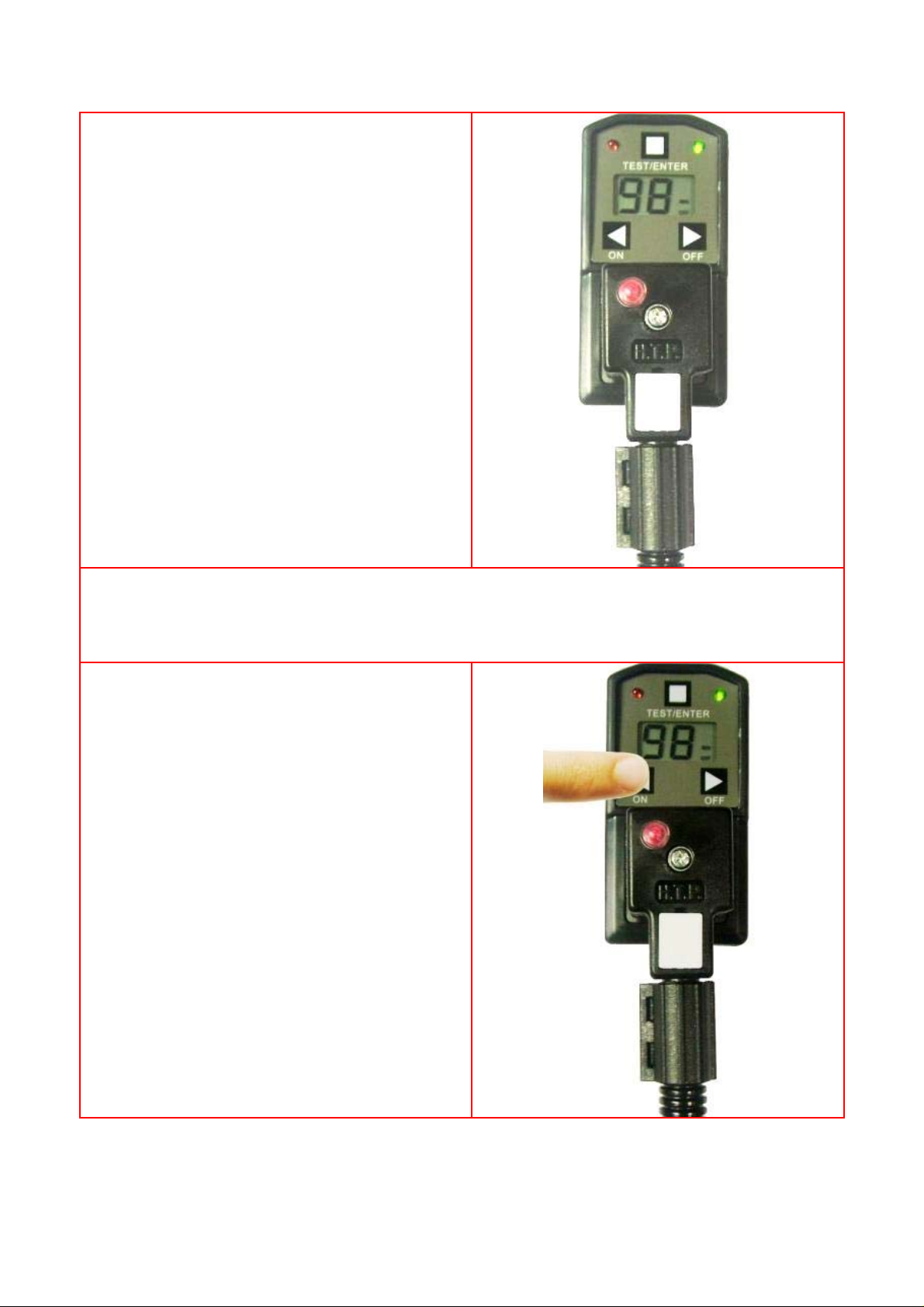
3)
When the unit is installed correctly and operational, you can
change the pre-set values to anything ranging from 0.5 sec
to 99 sec. for the ON time.
To change the ON time simply press the left ‘on’ button for
3 sec. and ‘sec’ will start flashing on the display.
The previously set ON time will appear on the display and
the ‘on’ led will be on.
You can now press the left ‘on’ button for increasing the
time or the right ‘off’ button to decrease the time.
N.B.: from 0 sec. to 9,5 sec., step of 0,5 sec.
from 10 sec. to 99 sec., step of 1 sec.
Pag. 2
Page 3

4)
Press the “test/enter” button to confirm your choise
INSTALLATION INSTRUCTIONS (part 2 of 2)
5)
You can change the pre-set values to anything ranging from
0.5 min to 99 min. for the OFF time.
To change the OFF time simply press the right ‘off’ button
for 3 sec. and ‘min’ will start flashing y on the display.
The previously set OFF time will appear on the display and
the ‘off’ led will be on.
You can now press the left ‘on’ button for increasing the
time or the right ‘off’ button to decrease the time.
N.B.: from 0 min. to 9,5 min., step of 0,5 min.
from 10 min. to 99 min., step of 1 min.
6)
Press the “test/enter” button to confirm your choise
Pag. 3
Page 4

HTP part number: TIMER-DIG
Digital Timer
ON TIME: from 0,5s to 99 s
OFF
TIME: from 0,5min to 99min
Technical data
Product type Digital timer
Supply Voltage
Max.Current
Current consumption 4mA max
Switch holding voltage 400V max
Inrush current 10A for 10ms
Duty cycle 100% ED
Switch life 3x10
Repeat accuracy ±0.01%
Operating temperature range -10°C...+50°C
Design standard VDE 0110-1/89
Protection class IP65 assembled
Connection
Earth h. h.12
OFF time From 0min to 9.5min., step 0.5min.
ON time From 0s. - 9.5 s., step 0.5 s.
24...240V AC/DC
1A
8
DIN43650/A/ISO4400
From 10min. to 99min., step 1min.
From 10s. to 99s., step 1 s.
Indicators GREEN LED: OFF phase
RED LED: ON phase
Flat Gasket NBR
Fixing screw M3X51,5mm
Housing material ABS V0
Housing colour Black
HIGH TECH PRODUCTS s.r.l Via Grazia Deledda, 20 - 24040 - Lallio (BG) ITALY
Tel.+39.035.692509 - Fax.+39.035.203291 - http://www.webhtp.com - info@webhtp.eu
 Loading...