

Page 1
Heat Pump
This manual must be used by a qualified installer/service technician. Read all instructions in this manual before installing. Perform steps
in the given order. Failure to comply could result in substantial property damage, severe personal injury, or death.
NOTE TO CONSUMER: PLEASE KEEP ALL INSTRUCTIONS FOR FUTURE REFERENCE.
Water Heater
INSTALLATION
START-UP
MAINTENANCE
PARTS
Hybrid Electric Heat Pump Water Heater Models
HPW-50-6
NOTICE: HTP reserves the right to make product changes or updates without notice and will not be held liable for typographical errors
in literature.
The surfaces of these products contacted by consumable water contain less than 0.25% lead by weight, as required by the Safe
Drinking Water Act, Section 1417.
120 Braley Rd. P.O. Box 429 East Freetown, MA 02717-0429 www.htproducts.com
LP-374 REV. 3.25.14
Page 2
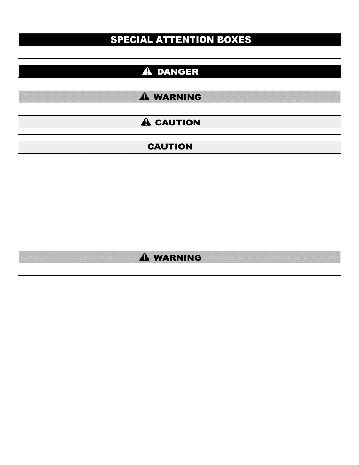
The following defined terms are used throughout this manual to bring attention to the presence of hazards of various risk
levels, or to important product information.
DANGER indicates an imminently hazardous situation which, if not avoided, will result in death or serious injury.
WARNING indicates a potentially hazardous situation which, if not avoided, could result in death or serious injury.
CAUTION indicates a potentially hazardous situation which, if not avoided, may result in minor or moderate injury.
CAUTION used without the safety alert symbol indicates a potentially hazardous situation which, if not avoided, may result in property
damage.
This manual must only be used by a qualified HVAC installer/service technician. Read all instructions in this manual before installing.
Perform steps in the order given. Failure to comply could result in substantial property damage, severe personal injury, or death.
FOREWORD
This manual is intended to be used in conjunction with other literature provided with the Hybrid Electric Heat Pump Water Heater. This
includes all related control information. It is important that this manual, all other documents included with this system, and additional
publications including the National Electrical Code, ANSI/NFPA 70, be reviewed in their entirety before beginning any work.
Installation should be made in accordance with the regulations of the local code authorities and utility companies which pertain to this
type of water heating equipment.
2
FOR THE INSTALLER
This water heater must be installed by qualified and licensed personnel. The installer should be guided by the instructions furnished
with the water heater, and with local codes and utility company requirements. In the absence of local codes, preference should be given
to the National Electrical Code, ANSI/NFPA 70.
INSTALLATIONS MUST COMPLY WITH:
Local, state, provincial, and national codes, laws, regulations and ordinances.
The latest version of the National Electrical Code, ANSI/NFPA No. 70, available from the National Fire Protection Association,
Batterymarch Park, Quincy, MA 02269.
In Canada – Canadian Electrical Code, CSA 22.1, available from Canadian Standards Association, 5060 Spectrum Way, Suite 100,
Mississauga, Ontario, Canada L4W 5N6.
LP-374 REV. 3.25.14
Page 3

TABLE OF CONTENTS
PART 1 – GENERAL SAFETY INFORMATION .......................................................................................................................... 4
A. PRECAUTIONS .......................................................................................................................................................................... 4
B. WATER TEMPERATURE ADJUSTMENT .................................................................................................................................. 4
C. COMBUSTIBLE MATERIALS ..................................................................................................................................................... 5
D. INSTALLATIONS IN THE STATE OF CALIFORNIA .................................................................................................................. 5
E. MAINTENANCE CONSIDERATIONS ......................................................................................................................................... 5
F. HYDROGEN GAS ....................................................................................................................................................................... 5
G. SAFETY CONSIDERATIONS .................................................................................................................................................... 6
H. SAFETY CONTROLS ................................................................................................................................................................. 6
PART 2 – INSTALLATION INSTRUCTIONS ............................................................................................................................... 6
A. DETERMINING WATER HEATER LOCATION .......................................................................................................................... 6
B. REQUIRED CLEARANCES ........................................................................................................................................................ 7
C. CONDENSATE DRAIN ............................................................................................................................................................... 8
D. THERMAL EXPANSION ............................................................................................................................................................. 8
E. WATER SUPPLY CONNECTIONS ............................................................................................................................................. 8
F. CONDENSATION DRAIN TUBES ............................................................................................................................................ 10
G. RELIEF VALVE......................................................................................................................................................................... 10
H. TO FILL THE WATER HEATER ............................................................................................................................................... 11
I. ELECTRICAL CONNECTIONS .................................................................................................................................................. 11
PART 3 – CONTROLS............................................................................................................................................................... 12
3
A. CONTROL OVERVIEW ............................................................................................................................................................ 12
B. DISPLAY OVERVIEW ............................................................................................................................................................... 13
C. SETTING THE WATER TEMPERATURE ................................................................................................................................ 14
D. ADJUSTING THE FUNCTION MODE ...................................................................................................................................... 15
E. ABOUT THE USER INTERFACE FEATURE BUTTONS .......................................................................................................... 15
F. USING THE BUTTONS IN COMBINATION .............................................................................................................................. 15
G. DEMAND RESPONSE ............................................................................................................................................................. 16
PART 4 – MAINTENANCE, VACATION, AND CLEANING ...................................................................................................... 17
A. ROUTINE PREVENTIVE MAINTENANCE ............................................................................................................................... 17
B. DRAINING THE WATER HEATER ........................................................................................................................................... 17
C. VACATION AND EXTENDED SHUTDOWN ............................................................................................................................ 18
D. CLEANING THE FILTER .......................................................................................................................................................... 18
E. CLEARING THE CONDENSATION DRAIN TUBES ................................................................................................................. 18
PART 5 – INSTALLATION CHECKLIST ................................................................................................................................... 18
PART 6 – STARTUP: WHAT TO EXPECT ................................................................................................................................ 19
PART 7 – MAINTENANCE CHECKLIST AND ERROR CODES .............................................................................................. 22
INSTALLATION AND MAINTENANCE NOTES ..................................................................................................................................................... 24
HTP CUSTOMER INSTALLATION RECORD FORM ............................................................................................................................................. 25
LP-374 REV. 3.25.14
Page 4
For your safety, the information in this manual must be followed to minimize the risk of fire, explosion, electric shock, and to prevent
property damage, personal injury, or death.
INSTALLER – Read all instructions in this manual before installing. Be sure to understand all instructions before installing or operating
this water heater, as this may save time and cost. Perform steps in the order given. Should you have problems understanding the
instructions in this manual, or any questions, STOP and get help from a qualified service technician or local electric utility.
FAILURE TO ADHERE TO THE GUIDELINES ON THIS PAGE CAN RESULT IN SUBSTANTIAL PROPERTY DAMAGE, SEVERE
PERSONAL INJURY, OR DEATH.
NOTE: If the water heater is exposed to the following, do not operate until all corrective steps have been made by a qualified
serviceman:
1. FIRE
2. DAMAGE
3. WATER
Any claims for damage or shortage in shipment must be filed immediately against the transportation company by the consignee.
High heat sources (sources generating heat 100oF / 37oC or greater, such as stove pipes, space heaters, etc.) may damage plastic
components of the water heater as well as plastic vent pipe materials. Such damages ARE NOT covered by warranty. It is
recommended to keep a minimum clearance of 8” from high heat sources. Observe heat source manufacturer instructions, as well as
local, state, provincial, and national codes, laws, regulations and ordinances when installing this water heater and related components
near high heat sources.
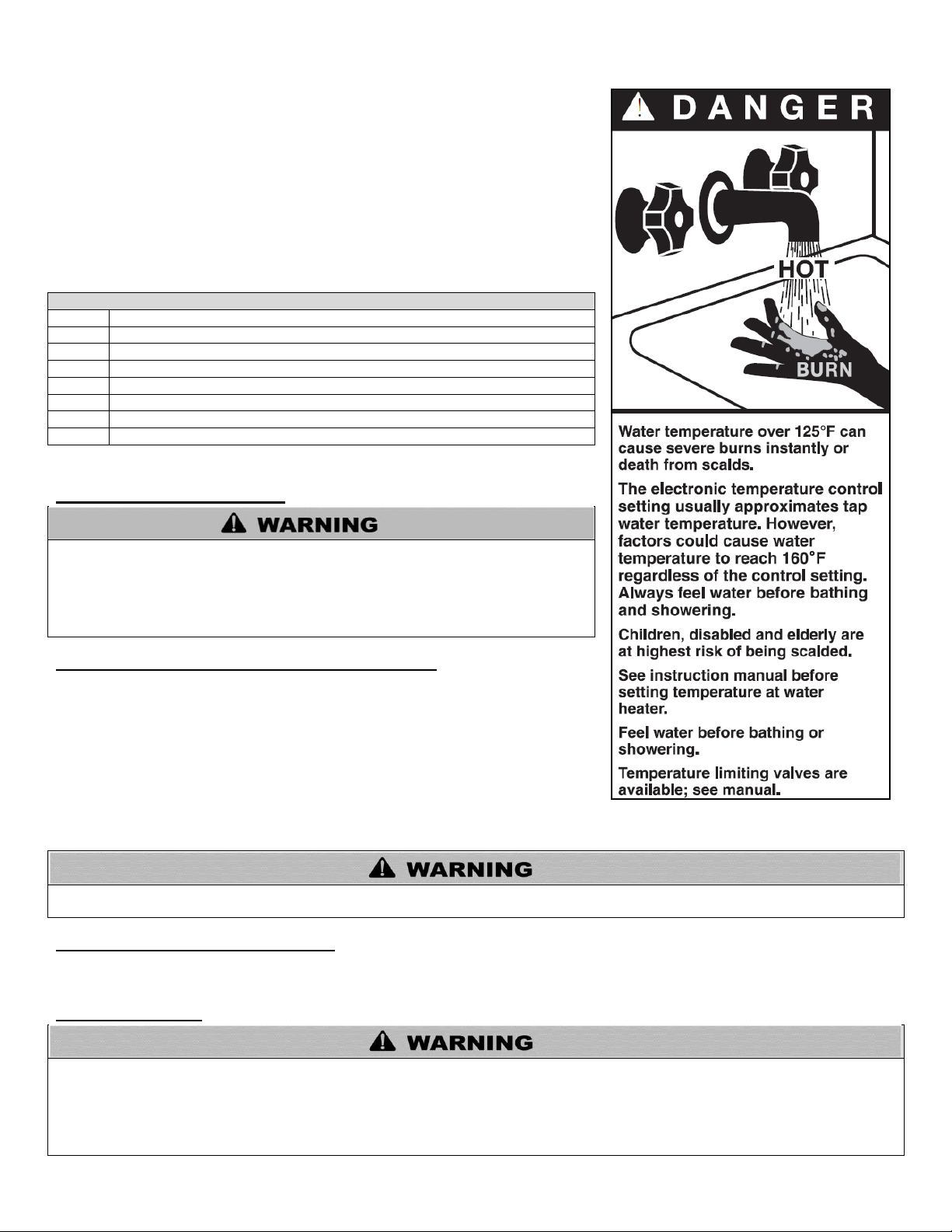
Water temperature over 125oF can instantly cause severe burns or death from scalds. Children, disabled, and the elderly are at the
highest risk of being scalded. See instruction manual before setting temperature at the water heater. Feel water before bathing or
showering! Temperature limiting valves are available.
PART 1 – GENERAL SAFETY INFORMATION
A. PRECAUTIONS
This water heater is for indoor installations only. Clearance to combustible materials: 0” top, bottom, sides and back. The water heater
must have room for service: 16” top, 12” sides, and 7” front and back are minimum recommended service clearances. If you cannot
provide these clearances, it may not be possible to service the water heater without removing it from its installation location.
This water heater needs at least 700 cubic feet of unconditioned indoor ambient air to operate properly. Do not install this water heater
in a closet or confined space. Ensure the water heater is installed on a floor that can support its full filled weight (660 lbs).
4
DO NOT USE THIS WATER HEATER IF ANY PART HAS BEEN UNDERWATER. Immediately call a qualified service technician.
Replace any part of the control unit that has been under water.
B. WATER TEMPERATURE ADJUSTMENT
LP-374 REV. 3.25.14
Page 5
Gasoline, as well as other flammable materials and liquids (adhesives, solvents, etc.),
and the vapors these items produce are extremely dangerous. DO NOT handle, use,
or store gasoline or other flammable or combustible materials anywhere near or in
the vicinity of the water heater. The arc drawn in the water heater controls can ignite
these vapors. Failure to follow these instructions can result in property damage,
serious personal injury, or death.
California Proposition 65 Warning: This product contains chemicals known to the State of California to cause cancer, birth defects, or
other reproductive harm.
Hydrogen gas can be produced in a hot water system that has not been used for a long period of time (generally two weeks or more).
HYDROGEN GAS IS EXTREMELY FLAMMABLE! To dissipate such gas and reduce the risk of injury, it is recommended that the
kitchen sink hot water faucet be opened for several minutes before using any electrical water heater connected to the hot water system.
If hydrogen is present, there will be an unusual sound, such as air escaping through the pipe as water begins to flow. Do not smoke or
use an open flame near the faucet while it is open. Failure to follow this warning could result in property damage, severe personal
injury, or death.
APPROXIMATE TIME / TEMPERATURE RELATIONSHIPS IN SCALDS
120oF
More than 5 minutes
125oF
1 ½ to 2 minutes
130oF
About 30 seconds
135oF
About 10 seconds
140oF
Less than 5 seconds
145oF
Less than 3 seconds
150oF
About 1 ½ seconds
155oF
About 1 second
Table 1 – Table Courtesy of Shriners Burn Institute
Figure 1
Safety and energy conservation are factors to be considered when selecting the water
temperature setting via the water heater user interface. Water temperatures above
125oF can cause severe burns or death from scalding. Be sure to read and follow the
warnings outlined on the label pictured in Figure 1. This label is also located on the
water heater near the top of the tank.
Mixing valves for reducing point-of-use water temperature by mixing hot and cold water
in branch water lines are available. Contact a licensed plumber or the local plumbing
authority for further information.
NOTE: Households with small children, disabled, or elderly persons may require
a 120oF or lower thermostat setting to prevent contact with “HOT” water.
C. COMBUSTIBLE MATERIALS
5
D. INSTALLATIONS IN THE STATE OF CALIFORNIA
California Law requires that residential water heaters must be braced, anchored, or
strapped to resist falling or horizontal displacement due to earthquake motions. For
residential water heaters up to 52 gallon capacity, a brochure with generic earthquake
bracing instructions can be obtained from: Office of the State Architect, 400 P Street,
Sacramento, CA 95814, or you may call 916-324-5315, or ask your water heater dealer
for more information.
Applicable local codes shall govern installation. For residential water heaters of a
capacity greater than 52 gallons, consult the local building jurisdiction for acceptable
bracing procedures.
E. MAINTENANCE CONSIDERATIONS
To avoid electric shock, disconnect electrical supply before performing maintenance.
To avoid severe burns, allow water heater to cool before performing maintenance.
F. HYDROGEN GAS
LP-374 REV. 3.25.14
Page 6
The cause of the high temperature condition must be investigated by a qualified service technician and corrective action must be taken
before placing the water heater in service again.
This water heater must be properly grounded before usage. Failure to comply could result in substantial property damage, severe
personal injury, or death.
G. SAFETY CONSIDERATIONS
1. Turn off power to the water heater if it has been subjected to overheating, fire, flood, or physical damage.
2. Do Not turn on water heater unless it is filled with water.
3. Do Not turn on water heater if cold water supply shut-off valve is closed.
4. Do Not store or use gasoline or other flammable vapors or liquids, such as adhesives or paint thinner, in the vicinity of this or any
other water heater. Open doors and windows for ventilation if such flammables must be stored near the water heater.
NOTE: Flammable vapors may be drawn by air currents from surrounding areas to the water heater.
5. If there is any difficulty in understanding or following the Control Instructions or the Maintenance and Cleaning Sections, it is
recommended that a qualified person or serviceman perform the work.
H. SAFETY CONTROLS
The water heater is equipped with two temperature-limiting controls (TCO and TOD) that are located above the heating element in
contact with the tank surface. If for any reason the water temperature becomes excessively high, the temperature-limiting control (TCO
or TOD) breaks the electrical circuit to the heating element. Once the control opens, it must be reset manually. Resetting the
temperature limiting controls should only be done by a qualified service technician.
To reset the temperature-limiting control:
1. Turn off the power to the water heater.
2. Remove the jacket access panel(s) and insulation. DO NOT remove the thermostat protective cover.
3. Press the red RESET button.
4. Replace the insulation and jacket access panel(s) before turning on power to the water heater.
6
PART 2 – INSTALLATION INSTRUCTIONS
A. DETERMINING WATER HEATER LOCATION
The location chosen for the water heater must take the following into consideration:
LOCAL INSTALLATION REGULATIONS
This water heater must be installed in accordance with these instructions, local codes, utility codes, and utility company requirements
or, in the absence of local codes, the latest edition of the National Electrical Code. It is available from some local libraries or can be
purchased from the National Fire Prevention Association, Batterymarch Park, Quincy, MA 02169 as booklet ANSI/NFPA 70.
POWER REQUIREMENTS
Check the markings on the rating plate of the water heater to verify the power supply corresponds to the water heater requirements
(240V/30A).
LOCATION
Locate the water heater indoors, in a clean, dry area as near as practical to the area of greatest heated water demand. Long
uninsulated water lines can waste heat, energy and money.
NOTE: Because this unit draws in air from the room to heat water, the room must be at least 10’ x 10’ x 7’ (700 cubic feet) or larger. If
the room is smaller, there must be a louvered door to allow for free air passage into the mechanical room. The louvered panel must be
at least 2 ft. by 3 ft. in size.
LP-374 REV. 3.25.14
Page 7
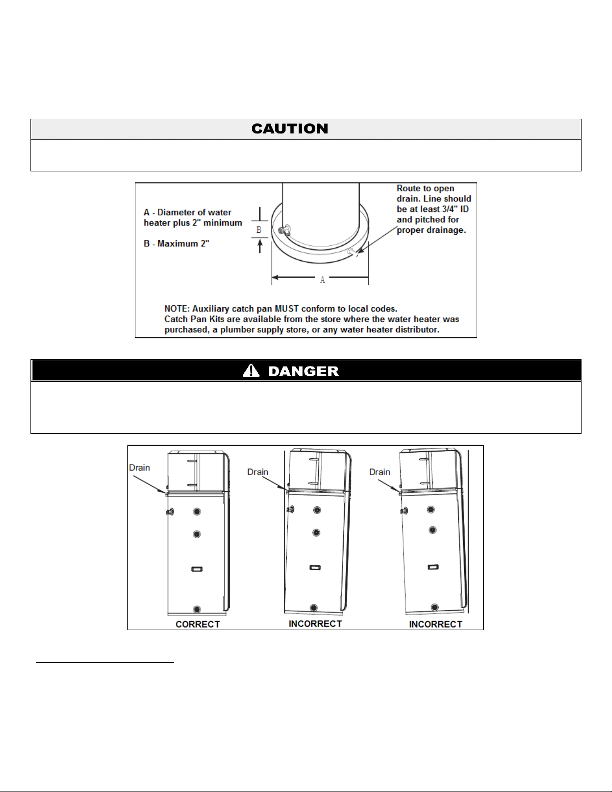
The water heater should not be located in an area where leakage of the tank or connections will result in damage to the area adjacent
to it or to lower floors of the structure. Where such areas cannot be avoided, it is recommended that a suitable, adequately drained
catch pan be installed under the water heater.
This water heater SHOULD NOT be installed in a space where liquids which give off flammable vapors are used or stored. Such liquids
include gasoline, LP gas (butane and propane), paint or adhesives and thinners, solvents, or removers. Because of natural air
movement in a room or other enclosed space, flammable vapors can be carried from where flammable liquids are being used or stored.
The operation of the control system within the water heater can ignite these vapors, causing an explosion or fire which may result in
property damage, as well as potentially severe burns or death to those in range.
Place the water heater in such a manner that the air filter, cover, and front panels can be removed to permit inspection and servicing,
such as removal of elements or cleaning of the filter.
The water heater and water lines should be protected from freezing temperatures and highly corrosive atmospheres. Do not install the
water heater in outdoor, unprotected areas.
7
Figure 2 – Catch Pan Detail
Figure 3 – To facilitate condensate drainage and proper operation, ensure the water heater is installed level.
B. REQUIRED CLEARANCES
In the event service is needed, there must be AT LEAST 16” top, 12” sides, and 7” minimum clearance (air space) between any object
and the front and rear covers.
LP-374 REV. 3.25.14
Page 8
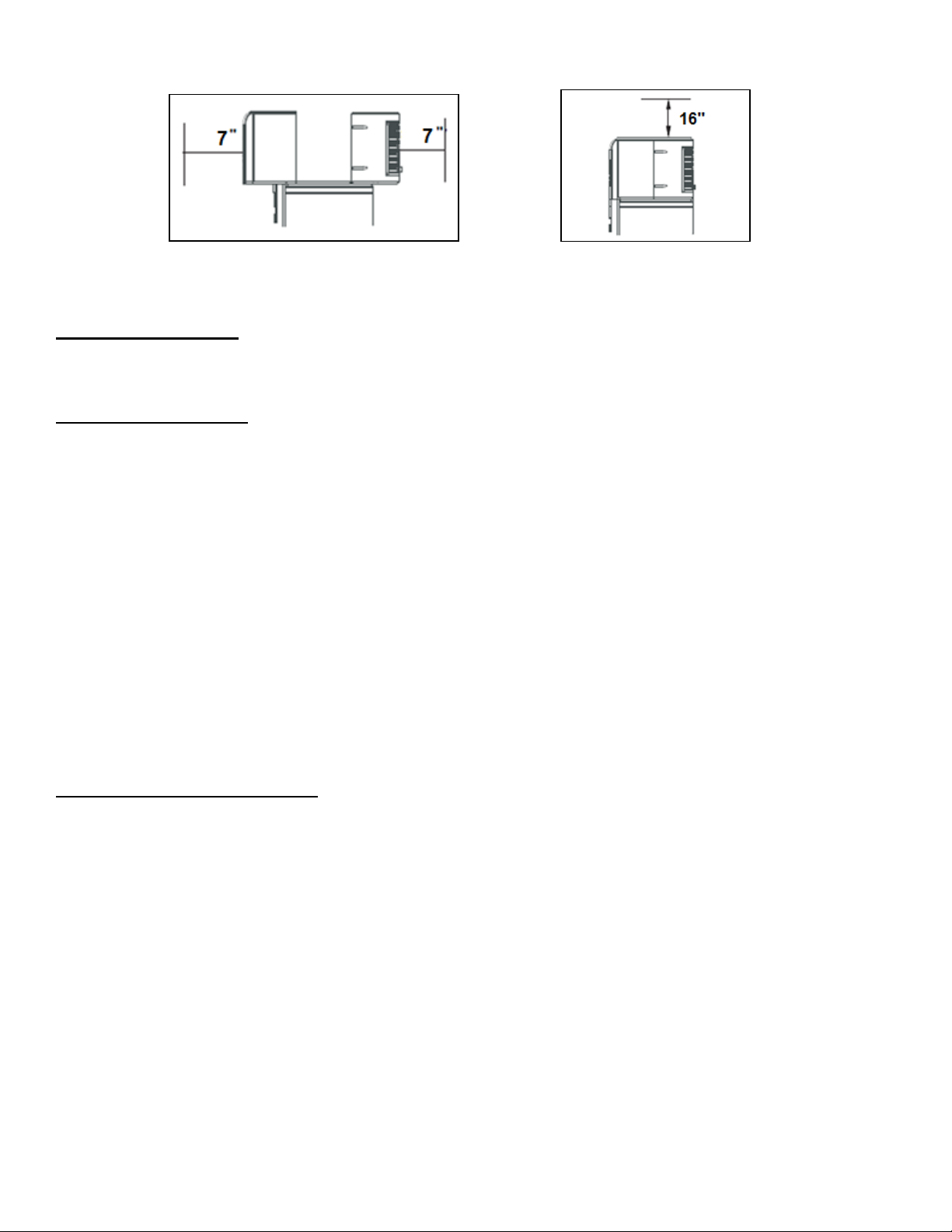
Figure 4 – Front and Rear Clearances Figure 5 – Top Clearance
A 16” minimum clearance is required to remove the filter for cleaning. The hot and cold water plumbing and electrical connections must
not interfere with the removal of the filter.
C. CONDENSATE DRAIN
The water heater has a condensate drain: therefore a drain must be available in close proximity to the unit. The drain must be no higher
than 36” above the floor (laundry drain is acceptable). If no drain is available, a common condensate pump with a capacity no less than
1 gallon/day must be purchased from a local plumbing supply store and installed.
D. THERMAL EXPANSION
Determine if a check valve exists in the inlet water line. It may have been installed in the cold water line as a separate backflow
preventer, or may be part of a pressure-reducing valve, water meter, or water softener. A check valve located in the cold water inlet line
can cause what is referred to as a “closed water system”. A cold water inlet line with no check valve or backflow prevention device is
referred to as an “open water system”.
As water is heated, it expands in volume and creates an increase in the pressure within the water system. This action is referred to as
“thermal expansion”. In an open water system, expanding water which exceeds the capacity of the water heater flows back into the city
main, where pressure is easily dissipated.
A closed water system prevents the expanding water from flowing back into the main supply line, and the resulting thermal expansion
can create a rapid and dangerous pressure increase in the water heater and system piping. This pressure increase can quickly reach
the safety limit of the relief valve, causing it to operate during each heating cycle. Thermal expansion, and the resulting rapid and
repeated expansion and contraction of components in the water heater and piping system, can cause premature failure of the relief
valve and possibly the water heater itself. Replacing the relief valve will not correct this problem.
The suggested method of controlling thermal expansion is to install an expansion tank in the cold water line between the water heater
and the check valve (refer to the illustration in Figure 6). The expansion tank is designed with an air cushion built in that compresses as
the system pressure increases, thereby relieving the thermal expansion and eliminating the repeated operation of the relief valve.
Other methods of controlling thermal expansion are available. Contact your installing contractor, water supplier, or plumbing inspector
for additional information regarding this subject.
8
E. WATER SUPPLY CONNECTIONS
Refer to Figures 6, 7, and 8 for suggested typical installations. The installation of unions or flexible copper connectors is recommended
on the hot and cold water connections so that the water heater may be easily disconnected for servicing if necessary. The HOT and
COLD water connections are clearly marked and are ¾” NPT on all models.
NOTE: Install a shut-off valve in the cold water line near the water heater. This will enable easier service and maintenance of the water
heater.
IMPORTANT: Do not apply heat to the HOT or COLD water connections. If sweat connections are used, sweat tubing to
adapter before fitting the adapter to the cold water connections on the water heater. Any heat applied to the hot or cold water
connections will permanently damage the dip tubes.
LP-374 REV. 3.25.14
Page 9

9
Figure 6 – Typical Water Heater Installation
Figure 7 – Typical Vertical and Horizontal Piping Details
LP-374 REV. 3.25.14
Page 10

Failure to properly drain condensate could lead to water leakage and property damage. Such damage IS NOT covered by warranty.
Do not attach the same hose to both condensate ports. Doing so will lead to improper operation, condensate leakage, and property
damage. Such damage IS NOT covered by warranty.
The pressure rating of the relief valve must not exceed 150 PSI, the maximum working pressure of the water heater as marked on the
rating plate. Failure to follow this warning could result in explosion, property damage, personal injury, or death.
The condensate line must remain unobstructed. If condensate is allowed to freeze in the line or obstructed in any other manner,
condensate can exit from the water appliance tee, resulting in potential water damage to property.
When installing a condensate pump, select one approved for use with condensing appliances. The condensate pump should have an
overflow switch to prevent property damage from spillage.
Figure 8 – Condensate Detail
F. CONDENSATION DRAIN TUBES
This unit has a built-in condensation tray to collect moisture discharge from the
evaporator coil. The water collected in the tray drains out of the tube on the back of
the unit. Two flexible hoses are included with this unit. It is important that both of
these hoses are attached to the two drain ports on the back of the unit.
Attach the shorter 3” hose to the top drain port.
Cut a 1 ½” piece off the long hose. Connect this piece to one end of the elbow
barbed fitting (included). Attach longer piece of the hose to the other end of the
barbed fitting.
Next, connect the short section with attached barbed fitting to the lower drain port
on the back of the unit, below the rear cover. . Direct the longer end to a drain in the
floor or no higher than 3’ above the floor. If such a drain is unavailable, a
condensate drain pump (not provided) must be purchased and installed.
NOTE: If condensate hose is kinked during shipping, DO NOT INSTALL ON THE
UNIT. A kinked hose should not be used, as condensate flow may be compromised
and overflow could occur. Replace kinked hose with hose of the same size,
available at most hardware or plumbing supply stores.
10
G. RELIEF VALVE
A new combination temperature and pressure relief valve, complying with the Standard for Relief Valves and Automatic Gas Shut-Off
Devices for Hot Water Supply Systems, ANSI Z21.22, is supplied and must remain installed in the opening provided and marked for the
purpose on the water heater. No valve of any type should be installed between the relief valve and the tank. Local codes shall govern
the installation of relief valves.
The BTUH rating of the relief valve must not be less than the input rating of the water heater as indicated on the rating label located on
the front of the water heater (1 watt = 3.412 BTUH).
Connect the outlet of the relief valve to a suitable open drain so that the discharge water cannot contact live electrical parts or persons
and to eliminate potential water damage.
Piping should be of a type approved for hot water distribution. The discharge line must be no smaller than the outlet of the valve and
must pitch downward from the valve to allow complete drainage (by gravity) of the relief valve and discharge line. The end of the
discharge line should not be threaded or concealed and should be protected from freezing. No valve of any type, restriction or reducer
coupling should be installed in the discharge line.
LP-374 REV. 3.25.14
Page 11

To reduce the risk of excessive pressures and temperatures in this water heater, install temperature and pressure protective equipment
required by local codes and no less than a combination temperature and pressure relief valve certified by a nationally recognized
testing laboratory that maintains periodic inspection of production of listed equipment or materials, as meeting the requirements for
Relief Valves and Automatic Gas Shutoff Devices for Hot Water Supply Systems, ANSI Z21.22. This valve must be marked with a
maximum set pressure not to exceed the marked maximum working pressure of the water heater, and orient it or provide tubing so that
any discharge from the valve exits only within 6 inches above, or at any distance below, the structural floor, and does not contact any
live electrical part. The discharge opening must not be blocked or reduced in size under any circumstances.
Failure to follow the instructions in this warning could result in explosion, property damage, personal injury, or death.
The tank must be full of water before water heater is turned on. The water heater warranty does not cover damage or failure resulting
from operation with an empty or partially empty tank.
Do not mis-wire electrical connections. 240V AC must be applied to the L1 and L2 wires shown in Figure 9. Failure to properly wire the
water heater may damage the compressor or other electrical components. Such failure will VOID the warranty.
Proper ground connection is essential. The presence of water in the piping and water heater does not provide sufficient conduction for a
ground. Nonmetallic piping, dielectric unions, flexible connectors, etc., can cause the water heater to be electrically isolated. Improper
grounding could result in severe personal injury or death due to electric shock.
Figure 9 – Branch Circuit Wiring Detail
H. TO FILL THE WATER HEATER
1. Make certain that the drain valve is completely closed.
2. Open the shut-off valve in the cold water supply line.
3. Open each hot water faucet slowly to allow the air to vent from the
water heater and piping.
A steady flow of water from the hot water faucet(s) indicates a full
water heater.
11
I. ELECTRICAL CONNECTIONS
The water heater must be wired to a separate 30 amp, 240V circuit
with copper conductors, surge protective device, and suitable
disconnecting means provided by a qualified electrician. All wiring
must conform to local codes or the latest edition of the National
Electrical Code ANSI/NFPA 70.
The water heater is completely wired to the junction box at the top of the water heater. An opening for a ½” or ¾” electrical fitting is
provided for field wiring connections.
The voltage requirements and wattage load for the water heater are specified on the rating label on the front of the water heater.
The branch circuit wiring should include either:
1. Metallic conduit or metallic sheathed cable approved for use as a grounding conductor and installed with fittings approved for the
purpose.
2. Nonmetallic sheathed cable, metallic conduit, or metallic sheathed cable not approved for use as a ground conductor shall include a
separate conductor for grounding. It should be attached to the ground terminals of the water heater and the electrical distribution box.
The water heater warranty does not cover any damage or defect caused by installation, attachment, or use of any type of energy-saving
or other unapproved devices (other than those authorized by the manufacturer) into, onto, or in conjunction with the water heater. The
use of unauthorized energy-saving devices may shorten the life of the water heater and may endanger life and property.
HTP disclaims any responsibility for such loss or injury resulting from the use of such unauthorized devices.
LP-374 REV. 3.25.14
Page 12

Figure 11 – Control Detail
If local codes require external application of insulation blanket kits, the manufacturer’s instructions included with the kit must be
carefully followed.
Application of any external insulation, blankets, or water pipe insulation to this water heater will require careful attention to
the following:
Do not cover the temperature and pressure relief valve.
Do not cover access panels to the heating elements.
Do not cover the electrical junction box of the water heater.
Do not cover the operating or warning labels attached to the water heater or attempt to relocate them on the exterior of the
insulation blanket.
Do not block any air inlets.
12
Figure 10 – Water heater with Cool Air Output Adapter connected to air pipe
NOTE: Diameter of air pipe must be 8”. Length must be no greater than 16’.
PART 3 – CONTROLS
A. CONTROL OVERVIEW
1. Display
2. Up Button
Increases data values or scrolls up a page.
3. Running Light
An illuminated light means the water heater is running. If the light is
unlit, the water heater has stopped running. A flashing light means
the water heater is in error and under protection.
4. Power Button
Starts or shuts down the water heater. NOTE: When the water
heater is in stand-by mode, this function can still be used.
5. Vacation Button
Use this button during extended periods of no water usage.
6. Down Button
Decreases data values or scrolls down a page.
7. ENTER Button
LP-374 REV. 3.25.14
Page 13

13
TERMS
DEFINITION
T2
Water Tank Temperature
T3a
Evaporator Inlet Temperature
T3b
Evaporator Outlet Temperature
T4
Compressor Discharge Temperature
T5
Ambient Temperature
Ts
Water Temperature Setpoint
UE
Upper Electric Heating Element
LE
Lower Electric Heating Element
Confirms inputs and locks or unlocks the key pad. Press this key for 3 seconds to lock or unlock the key pad. In order to confirm Mode
or set point temperature inputs, hold this key for 10 seconds.
8. MODE Button
Allows users to choose an operating mode.
Detailed Description of Control Functions
1. Auto-Confirm Function
10 seconds after pressing control pad keys, the auto-confirm function automatically accepts entered data and returns the water heater
into operating mode.
2. Auto-Lock Function
If control pad keys have not been pressed for 1 minute, the control pad will automatically lock. To unlock the control pad, press and
hold the ENTER key for 3 seconds.
3. Diagnostic Function
This function allows service technicians or users to view water heater parameters. To open the Diagnostic Function, unlock the control.
Once the control is unlocked, press ENTER and the UP arrow simultaneously for 1 second. This will allow the user to view the water
heater parameters. To exit, press ENTER and UP.
Table 2 is a descriptive list of the terms that will be found in the Diagnostic Function mode.
DIAGNOSTIC TERMS
Table 2 – Diagnostic Terminology
4. Screen Save
To extend display life, the display will dim when there is no operation for a period of time. Press any key to light the screen.
B. DISPLAY OVERVIEW
Figure 12 – Display Detail
1. Peak Load Shifting Mode 1
When in this mode, this icon will light. The heat pump mode will run, and users can set water temperature.
2. Peak Load Shifting Mode 2
When in this mode, this icon will light. The heat pump mode will run. Users cannot set water temperature. Water temperature is
automatically set at 110oF.
LP-374 REV. 3.25.14
Page 14

14
There is a hot water scald potential if the water temperature is set too high. Households with small children, disabled, or elderly persons
may require a 120oF or lower thermostat setting to prevent contact with scalding water.
APPROXIMATE TIME / TEMPERATURE
RELATIONSHIPS IN SCALDS
120oF
More than 5 minutes
125oF
1 ½ to 2 minutes
130oF
About 30 seconds
135oF
About 10 seconds
140oF
Less than 5 seconds
145oF
Less than 3 seconds
150oF
About 1 ½ seconds
155oF
About 1 second
Table 3 – Table Courtesy of Shriners Burn Institute
3. High Temperature Setting
If the temperature set by user or actual temperature is above 120oF, this icon lights. This icon will shut off if water temperature is less
than 120oF, or when the display is in screen save mode.
4. Lock Icon
This icon lights when the key pad is locked, and will shut off when the key pad is unlocked.
5. Alarm Icon
The alarm icon will flash and an alarm will sound when the water heater is in error and under protection, and continue to flash and
sound until the reason for the error is solved or the water heater is reset.
6. Vacation
The Vacation icon lights when this feature this feature is in use. Vacation Mode greatly reduces energy usage. See Section E on pages
18 - 19 for more on Vacation Mode.
7. Auto Mode Icon
This icon will flash slowly when the water heater is in Auto Mode. See Section D on page 18 for more on Auto Mode.
8. Economy Mode Icon
This icon will flash slowly when the water heater is in Economy Mode. See Section D on page 18 for more on Economy Mode.
9. Electric Mode Icon
This icon will flash slowly when the water heater is in Electric Mode. See Section D on page 18 for more on Electric Mode.
10. Water Temperature Mode Icon
This icon has three phases:
When water temperature is less than 140oF, and set point water temperature is greater than 120oF, all three phases will be lit.
When water temperature is less than 120oF, and set point water temperature is greater than 110oF, the lower two phases will
be lit.
When water temperature is less than 110oF, and set point water temperature is greater than 100oF, the lowest phase will be lit.
11. Main Screen
The display will light once the power supply is connected. During normal
usage, this shows water temperature. Error or protection codes are
displayed when the water heater is under error or protection. The main
screen returns to normal when error or protection is cleared. Pressing
ENTER and UP simultaneously will query the water heater. Parameters
display on this screen.
C. SETTING THE WATER TEMPERATURE
The temperature of the water in the water heater can be regulated by
adjusting the temperature setting up or down using the arrow keys on
the control panel.
Consider safety and energy conservation when selecting the water
heater temperature setting. The lower the temperature setting, the greater the savings in energy and operating costs. To comply with
safety regulations, water temperature is factory set at 120oF. This is the recommended starting set point.
Water temperatures above 125oF can cause severe burns or death from scalding. Be sure to read and follow the warnings outlined in
this manual and on the label located on the water heater near the upper element access panel.
Mixing valves for reducing point-of-use water temperature by mixing hot and cold water in branch water lines are available. Contact a
licensed plumber or the local plumbing authority for further information.
To Adjust the Temperature
First, unlock the key pad by pressing and holding the ENTER key for 3 seconds. Next, press the UP or DOWN arrows on the control
panel key pad to increase or decrease the water temperature. If increasing the water temperature beyond 120oF, a CAUTION triangle
and thermometer icon will appear on the appliance display to warn the user that raising the water temperature also increases scalding
risk.
LP-374 REV. 3.25.14
Page 15

15
After the desired temperature setting has been selected, press ENTER to accept the setting. If the water temperature setting is
changed and the ENTER key is not pressed to accept it after 10 seconds of no control activity, the control will automatically revert to the
previous temperature setting.
D. ADJUSTING THE FUNCTION MODE
This water heater defaults to the Auto operating Mode. The Auto Mode is the recommended setting for this water heater, but can be
changed if desired. Available modes are listed below and can be found by pressing the MODE button when the water heating control is
unlocked.
Economy Mode
The Economy Mode is the most energy efficient. This mode takes heat from the surrounding air to heat the water. It takes more time to
heat water in Economy Mode, so this mode may NOT be sufficient in a high-demand situation, such as a large household or company.
Standard Electric Mode
This mode uses only the upper and lower heating resistance elements to heat water. It takes less time to heat water, but Standard
Electric Mode is also the LEAST efficient operating mode on the water heater.
Auto Mode – FACTORY RECOMMENDED SETTING
Auto Mode combines the energy efficiency of the Economy Mode with the recovery speed and power of Electric Mode. Auto Mode is
recommended for normal water usage.
To access any of these modes:
1. Press and hold the ENTER key for three seconds to unlock the key pad.
2. Press the MODE button.
3. Select the desired operating mode by using the UP and DOWN keys to scroll through the options.
4. Once you’ve selected an operating mode, press the ENTER key or wait ten seconds for the Auto-Confirm Function to automatically
accept the mode.
E. ABOUT THE USER INTERFACE FEATURE BUTTONS
Vacation Mode
This feature is used when you will be away from home for an extended period of time. In this mode, the unit will drop the water
temperature down to 50oF and use the most efficient heating mode to conserve energy while the water heater is sitting idle. The unit will
automatically resume heating one day before your return, so hot water will be available.
To use Vacation Mode:
1. Press and hold the ENTER key for three seconds to unlock the key pad.
2. Press the VACATION button.
3. Press the UP and DOWN arrow keys to select the # of days you will be away (default is 7 days). Then, press the ENTER key or wait
ten seconds for the Auto-Confirm Function to automatically accept the number of days.
For example, if you will be gone 14 days, select 14 with the key pad. The water heater will then automatically drop the water
temperature to 50oF for 13 days. At the end of the 13th day, the water heater will automatically return to the previous operating mode
and heat the water to the original temperature setting.
The green light will be lit when this feature is on, indicating that the control is locked.
Control Lock
The key pad can be locked out to prevent accidental key inputs. Simply press and hold the ENTER button for three seconds. The
display will show “controls are locked” and the green light will be lit. No other key presses will be allowed when the controls are locked.
To deactivate the lock, press and hold the ENTER key for three seconds. The green light will fade and the screen will go to the default
display.
F. USING THE BUTTONS IN COMBINATION
1. Temperature Measurement Conversion
The display defaults to temperature readings in Fahrenheit (F). To show the temperature in Celsius (C) press and hold the ENTER and
MODE buttons simultaneously for one second. To change from C to F, repeat the process.
LP-374 REV. 3.25.14
Page 16

DISPLAY CODE (2)
DESCRIPTION
VALUE (1)
2
Actual Temperature
T2, Water Tank Temperature
31
Actual Temperature
T3a, Evaporator Inlet Temperature
32
Actual Temperature
T3b, Evaporator Outlet Temperature
4
Actual Temperature
T4, Compressor Discharge Temperature
5
Actual Temperature
T5, Ambient Temperature
6
Actual Current
Current Value
7
Malfunction Protection Code
The most recent error
8
Malfunction Protection Code
Second most recent error
9
Malfunction Protection Code
Third most recent error
A
Fan Motor Operating Time 1
Actual operating time = Fan motor operating time 1 + Fan motor
operating time 2
b
Fan Motor Operating Time 2
C
Heat Pump Protection Counter
Heat pump protection counter
Figure 14 – Demand Response Installation
2. Diagnostic Function
To query appliance diagnostics, press and hold the ENTER and UP buttons together for one second. After opening the Diagnostic
Function, use the UP and DOWN arrows to scroll through the diagnostics.
Table 4 – Diagnostic Function List – See Screen Shot in Figure 13 for location of Value (1) and Display Code (2)
To exit appliance diagnostics, press and hold the ENTER and UP buttons together for one second; otherwise, the appliance will exit
automatically after one minute of no activity.
16
Figure 13 – Diagnostic Function Screen Shot
3. Clear Malfunction
To clear malfunction, press and hold ENTER and DOWN simultaneously for one second.
4. Clear Alarm
To clear alarm, press and hold ENTER and VACATION simultaneously for one
second.
G. DEMAND RESPONSE
This water heater is compatible with the optional Demand Response (DR) module
(purchased separately). Contact your local utility to see if your area is using DR
technology.
INSTALLATION
The DR module is equipped with magnets in the base of the module that enable it
to attach to the painted metal exterior of the water heater. Details on how to
connect the cables can be found in instructions included with the module.
Once the cable from the DR module is plugged into the water heater connection,
follow the power-up directions included with the module. As soon as the DR
module is operating, the water heater is ready to receive DR signals.
QUICK GUIDE
If your local utility company utilizes DR technology, the DR module will receive
signals from the utility company. One of four signals will be sent: Low represents
that the lowest energy cost rate is available. Medium and High signals represent
increasing energy cost steps, and the Critical signal represents “peak rate” energy.
LP-374 REV. 3.25.14
Page 17

17
Before manually operating the relief valve, make certain no one will be exposed to the hot water released by the valve. The water may
be hot enough to create a scald hazard. The water should be released into a suitable drain to prevent property damage, severe
personal injury, or death from scalds.
NOTE: If the temperature and pressure relief valve on the hot water heater discharges periodically, this may be due to thermal
expansion in a closed water system. Contact the water supplier or your plumbing contractor on how to correct this. Do not plug the relief
valve outlet.
Before manually operating the relief valve, make certain no one will be exposed to the hot water released by the valve. The water
drained from the tank may be hot enough to present a scald hazard. Failure to do so could lead to property damage, serious personal
injury, or death.
Shut off power to the water heater before draining water. Failure to do so could lead to property damage, serious personal injury, or
death.
Figure 15 – Drain Valve Location
A heat pump water heater equipped with a DR module will automatically recognize what energy cost rate is available and adjust its
mode and temperature setting to use less energy when rates are medium, high, and critical. When the heat pump water heater
responds to these signals, it will display the letters “EP” in the screen, along with other information indicating that energy pricing periods
are in effect. When the signal is low or when no DR module is connected, the unit will continue to run.
PART 4 – MAINTENANCE, VACATION, AND CLEANING
A. ROUTINE PREVENTIVE MAINTENANCE
If properly maintained, your water heater will provide years of dependable, trouble-free service. It is suggested that a routine preventive
maintenance program be established and followed by the user.
Periodic Inspection
It is further recommended that a periodic inspection of the operating controls, heating elements, and wiring should be conducted by
service personnel qualified in electric water heater repair.
Most electrical water heaters, even when new, make some sound when in operation. If the hissing or singing sound level increases
excessively, the electric heating element may have scale buildup and require cleaning or replacement. Contact a qualified installer or
plumber for inspection.
Temperature and Pressure Relief Valve
At least once a year, lift and release the lever handle on the temperature and pressure relief valve, located on the back left side of the
water heater, to make sure the valve operates freely. Allow several gallons of water to flush through the discharge line to an open drain.
Flushing the Tank
The water heater tank can act as a settling basin for solids suspended in water. It is therefore not uncommon for hard water deposits to
accumulate in the bottom of the tank. To clean the tank of these deposits, open the drain valve (located under the large decorative
cover near the bottom of the unit) and drain a few quarts of water from the water heater every month.
B. DRAINING THE WATER HEATER
Attach a garden hose to the drain valve located at the
bottom of the unit and direct the hose to a drain. The
decorative front cover must be removed to access
this valve.
In order to completely drain the water heater, turn off
the cold water supply. Open a hot water faucet or lift
the handle on the relief valve to admit air into the
tank.
Open the drain valve. When done draining, close the drain valve, reopen the cold water supply, and refill the tank. Open a hot water
faucet to vent the system of air.
LP-374 REV. 3.25.14
Page 18

Hydrogen gas can be produced in a hot water system that has not been used for a long period of time (generally two weeks or more).
HYDROGEN GAS IS EXTREMELY FLAMMABLE! To dissipate such gas and reduce the risk of injury or death, it is recommended that
the kitchen sink hot water faucet be opened for several minutes before using any electrical water heater connected to the hot water
system. If hydrogen is present, there will be an unusual sound, such as air escaping through the pipe as water begins to flow. Do not
smoke or use an open flame near the faucet while it is open.
Figure 16 – Filter Detail
C. VACATION AND EXTENDED SHUTDOWN
If the water heater is to remain idle for an extended period of time, the power and water to the water heater should be turned off to
conserve energy and prevent a buildup of dangerous hydrogen gas.
The water heater and piping should be drained if they might be subjected to freezing temperatures.
After a long shutdown period, the water heater operation and controls should be checked by qualified service personnel. Make certain
the water heater is completely refilled before placing it in operation.
D. CLEANING THE FILTER
In Auto and Economy modes, the water heater moves air through the system and out of the back of the unit. The filter is in place to
protect the evaporator from dirt or dust.
A clean air filter is important to achieve highest efficiency. This filter will need to be cleaned at least once a year. When the filter
requires cleaning, an alarm will sound. The screen will display instructions that the filter needs to be cleaned.
NOTE: If the filter gets too dirty for heat pump to operate properly, the unit
will automatically switch to Electric Mode and energy savings will be lost.
Leave the power on and remove the filter from the top of the water heater.
Grasp the handle and slide the filter straight up until it clears the cover.
Once the filter has been removed, wipe it clean with a damp rag, or rinse it
in warm water.
Once the filter has been cleaned, it can be replaced by aligning it into the
slot in the top of the water heater and sliding it down into place. When the
handle is flush with the top of the cover, it is seated.
When the clean filter has been reinstalled, press ENTER.
IMPORTANT: The filter must be cleaned when the alarm is sounded. A
dirty filter will make the system work harder and result in a reduction of
efficiency and possible damage to the system. In order to get the best
energy efficiency available, make sure your filter is clean.
18
E. CLEARING THE CONDENSATION DRAIN TUBES
There are two drain hoses that are attached to the back of the water heater.
If both of these clog, water will spill down the outside of the unit.
The primary drain is intended to carry all condensate away. If it is clogged or the hose is kinked, the condensate will exit the secondary
drain tube and onto the floor. This is intended as a notification to the user that the primary drain is clogged. Remove the drain hose,
clear any debris, and reattach.
Periodically inspect the drain lines and clear any debris that may have collected in the lines.
PART 5 – INSTALLATION CHECKLIST
1. Tank Location:
Is room size less than 10’ x 10’ x 7’ (700 cu. Ft.)? If yes, louvered door or similar ventilation is needed.
Is the rear of unit 7” away from wall?
Is the front of unit clear of any obstructions?
Is the water heater level? If not, add shims under the base of the unit.
Is a catch pan installed to prevent damage to surrounding area in case water heater leaks?
2. Plumbing connections:
Do plumbing connections allow air filter removal?
LP-374 REV. 3.25.14
Page 19

19
ELAPSED TIME
WATER HEATER ACTIONS
COMMENTS
0 to 1.5 minutes
Unit is silent.
This 3 minute off time prevents compressor damage.
1.5 to 3 minutes
Fans turn on.
3 to 8 minutes
Compressor turns on and runs for
5 minutes.
This 5 minute period ensures the tank is full of water (dry-fire
prevention).
8 to 30 minutes
Compressor turns off. Upper
element turns on for about 20
minutes.
Quickly provides initial amount of hot water for user (about 25
gallons).
30 minutes and beyond
Upper element turns off and
compressor turns back on.
Uses efficient heat pump for majority of heating.
Are the tank and all related plumbing connections leak free?
3. Condensate lines are in place:
a. Short tube on upper drain nozzle and directed to catch pan or floor drain.
b. Longer tube on lower drain nozzle and directed into a floor drain or a condensate pump.
4. Temperature and pressure relief valve is working and drain lines completed per local codes.
5. Electrical connections allow air filter removal.
6. Verify control displays 120oF in Auto Mode.
7. Front cover is in place.
PART 6 – STARTUP: WHAT TO EXPECT
After the water heater has been installed with all electrical and water connections secure and checked, fill the unit with water. While
filling, vent the tank by opening a hot water faucet somewhere in the home (preferably at the kitchen sink). When water flows freely, the
tank is full.
Once the tank is full, energize the water heater. Press the POWER button on the user interface to turn the water heater on. Once
powered, the control will display a reminder to ensure the water heater is full. Press POWER again to acknowledge that the water
heater is full.
NOTE: Table 5 outlines what can be expected next.
Table 5
NOTE: The heat pump operating range is 45oF to 120oF. If the ambient temperature is outside this range, the heat pump will not be
able to run and the backup electric elements will operate until the ambient temperature returns to operating range.
LP-374 REV. 3.25.14
Page 20

20
Figure 17 - Parts
Figure 18 – Junction Box Parts
LP-374 REV. 3.25.14
Page 21

21
ITEM #
DESCRIPTION
REPLACEMENT PART #
1
Inlet Dip Tube
7200P-001
2
Magnesium Anode Rod (not shown)
7200P-002
3
Outlet Dip Tube
7200P-003
4
Electric Heating Element
7200P-004
5
Display
7200P-005
6
Display Panel
7200P-006
7
Fan Motor Cover
7200P-007
8
Compressor
7200P-008
9
Fan Wheel (not shown)
7200P-009
10
Front Shroud
7200P-010
11
Junction Box
7200P-011
12
Junction Box Cover
7200P-012
13
Left Rail (not shown)
7200P-013
14
Evaporator Motor
7200P-014
15
Fan Motor Cover
7200P-015
16
Top Cover
7200P-016
17
Right Rail (not shown)
7200P-017
18
Mesh Screen
7200P-018
19
Filter
7200P-019
20
Rear Shroud
7200P-020
21
Electronic Control Box Cover
7200P-021
22
Electronic Control Box Assembly
7200P-022
23
Compressor Discharge Tube Assembly
7200P-023
24
Strainer Tube
7200P-024
25
Strainer
7200P-025
26
Thermal Expansion Valve Assembly
7200P-026
27
Liquid Storage Tank Assembly
7200P-027
28
Evaporator
7200P-028
29
Front Decorative Cover
7200P-029
30
Upper Element Cover
7200P-030
31
Lower Element Cover
7200P-031
Figure 19 – Heat Pump Parts, Sensors, and T2 Sensor (Upper Element) Locations
Table 6 – Replacement Parts List
LP-374 REV. 3.25.14
Page 22

PROBLEM
POSSIBLE CAUSES
WHAT TO DO
Water
heater is
Noisy
Fans are used to move air through the
system. Fan noise volume will vary as water
is heated.
Some amount of fan noise is normal (similar to the blower on a central
heating or cooling system). If you hear an abnormal noise, like a
knocking sound, or the noise level seems unusually loud, contact
service.
If noise level has been increasing over the last weeks or months, the
filter may be dirty, thus making the fans work harder. Clean the filter.
Water
heater is
making
the room
too cold
Room is not vented properly or is too small
If the room is smaller than 10’ x 10’ x 7’, the installation must have a
louvered door or other means to allow air exchange with surrounding
rooms.
Water
dripping
down the
outside of
the water
heater
Condensate drain hoses are not connected
Two drain hoses are included with your water heater. Connect the longer
6’ hose to the lower condensate drain port. Connect the short 3” hose to
the upper condensate drain port.
Condensate drain hoses are kinked or
clogged
Remove each drain hose and clear any debris from the line. You can
use a wire hanger or small screwdriver to clear out any debris in the
drain port on the unit.
Inlet/Outlet water connections are not
tightened
Tighten the inlet and outlet pipe connections.
NOTE: DO NOT OVER-TIGHTEN.
Not
enough or
no hot
water
Water usage may have exceeded the
capacity of the water heater
Wait for the water heater to recover after abnormal demand.
Fuse is blown or circuit breaker tripped
Replace fuse or reset circuit breaker.
Electric supply may be off
Make sure electric supply to water heater and disconnect switch, if used,
are in the ON position.
Water temperature may be set too low.
See Setting the Water Temperature, Part 3 C.
Leaking or open hot water faucets.
Make sure all faucets are closed.
Electric service to your home may be
interrupted.
Contact the local electric utility.
Improper wiring
Do not attempt to repair wiring. Call for service.
Manual reset limit (TCO)
A tripped TCO could mean there is a serious issue with the water heater.
Call for service.
Cold water inlet temperature may be colder
during winter months.
This is normal. Colder inlet water takes longer to heat.
Water is
too hot
Water temperature is set too high
See Setting the Water Temperature, Part 3 C.
For your safety, DO NOT attempt repair of electrical wiring, controls, heating elements, or safety devices. Refer repairs
to qualified service personnel.
Electronic control has failed
Call for service.
Rumbling
Noise
Water conditions in your home caused a
buildup of scale or mineral deposits on the
heating elements
Call for service.
Relief
valve
producing
popping
noise or
draining
Pressure buildup caused by thermal
expansion to a closed system
This unacceptable condition must be corrected. Contact the water
supplier or plumbing contractor for service. Do not plug the relief valve
outlet.
An alarm
sounds
and the
screen
states
“The Filter
Needs
Cleaning”.
The filter requires cleaning. A clean filter is
necessary for effective operation
Follow the instructions on how to remove and clean the filter, Part 4 D.
PART 7 – MAINTENANCE CHECKLIST AND ERROR CODES
Before calling for service, follow the troubleshooting tips below. You may not have to call for service.
22
Table 7 – Troubleshooting Table
LP-374 REV. 3.25.14
Page 23

ERROR
CODE
DESCRIPTION
WHAT TO DO
ALL
ALL
Inspect for proximity to high voltage power sources.
E0
T2 sensor error
1. Check if sensor wires are correctly connected and/or damaged.
2. Check if T2 sensor is damaged.
3. Check T2 sensor resistance.
4. Check actual temperature in Celsius 0oC ~ 60oC (tolerance +5oC)
E1
T3a sensor error
1. Check if sensor wires are correctly connected and/or damaged.
2. Check if T3a sensor is damaged.
3. Check T3a sensor resistance.
4. Check actual temperature, range is 23oF to 86oF.
5. Check for damage to TXV and/or capillary probe.
E4
T3b sensor error
1. Check if sensor wires are correctly connected and/or damaged.
2. Check if T3b sensor is damaged.
3. Check T3b sensor resistance.
4. Check actual temperature, range is 32oF to 86oF.
E5
T4 sensor error
1. Check if sensor wires are correctly connected and/or damaged.
2. Check if T4 sensor is damaged.
3. Check T4 sensor resistance
4. Check actual temperature, range is 86oF to 230oF.
5. Check for refrigerant leakage or damaged piping.
E6
T5 sensor error
1. Check if sensor wires are correctly connected and/or damaged.
2. Check if T5 sensor is damaged.
3. Check T5 sensor resistance.
4. Check position of sensor tab, flat to be at back.
E7
Heat pump error
1. Powering the water heater off and restart.
2. Press ENTER and UP to enter Diagnostic Function and check error code history.
E8
Water temperature too high
(T2 greater than 165oF)
1. Check if sensor wires are correctly connected and/or damaged.
2. Check if T2 sensor is damaged.
3. Power water heater off and restart.
4. Replace T2 sensor.
P0
Run condition C
Checked every 30 minutes. T3a temperature should be greater than 32oF. Recheck after 30
minutes.
P1
Run condition D
Checked every 30 minutes. Readings from (T3b – T3a) sensors must be greater than 3oF.
P2
Run condition E
Checked continuously. T4 sensor must be greater than 240oF.
P4
High compressor current
1. Ensure compressor operating current and voltage match the rating label. .
2. Check if compressor or related connections are damaged.
P5
Air filter needs cleaning
1. Remove the air filter and clean with water or compressed air.
2. Press and hold ENTER and DOWN simultaneously to reset system.
P6
Run condition A
Checked 5 minutes from compressor startup. T4 temperature must increase greater than
15oF.
P7
Run condition B
Checked every 30 minutes. T4 temperature should be greater than 100oF.
P8
Upper element error
1. Powering the water heater off and restart.
2. Check electrical supply voltage.
3. Remove cover and check element connections and/or damage.
4. Check for damage to power wire through current sensor loop in control board.
PA
Lower element error
1. Powering the water heater off and restart.
2. Check electrical supply voltage.
3. Remove cover and check element connections and/or damage.
4. Check for damage to power wire through current sensor loop in control board.
The following table describes error codes and possible solutions. If your water heater displays an error code, call a qualified service
agent to fix the problem.
23
Table 8 – Error Codes - NOTE: See Figure 19 for sensor locations.
LP-374 REV. 3.25.14
Page 24

24
INSTALLATION AND MAINTENANCE NOTES
LP-374 REV. 3.25.14
Page 25

Customer’s Name:
Installation Address:
Date of Installation:
Installer’s Code/Name:
Product Serial Number(s):
Comments:
Installer’s Phone Number:
Signed by Installer:
Signed by Customer:
HTP CUSTOMER INSTALLATION RECORD FORM
The following form should be completed by the installer for you to keep as a record of the installation in case of a warranty claim. After
reading the important notes at the bottom of the page, please also sign this document.
25
IMPORTANT:
Customer: Please only sign after the installer has reviewed the installation, safety, proper operation and maintenance of the
system. In the case that the system has any problems, please call the installer. If you are unable to make contact, please
contact your HTP Sales Representative.
Distributor/Dealer: Please insert contact details.
LP-374 REV. 3.25.14
 Loading...