

Page 1
Installation
DANGER
!
NOTICE
WARNING
!
Start-Up
Maintenance
Parts
Warranty
Elite XL®
Commercial Boilers
ELX-400 / 500 / 650 / 800 / 1000 / 1500 / 2000
Models*
*”B” Denotes Boiler Models,
”N” Denotes Natural Gas, “LP” Denotes Propane,
and “F” Denotes Floor Mount Models
Example Model: ELX-1000FBN
This manual must only be used by a qualied installer / service technician. Read all instructions in this manual before installing.
Perform steps in the given order. Failure to do so could result in substantial property damage, severe personal injury, or death.
Improper installation, adjustment, alteration, service, or maintenance could void product warranty and cause property
damage, severe personal injury, or death.
California Proposition 65 Warning: This product contains chemicals known to the State of California to cause cancer, birth
defects, or other reproductive harm.
Heat Exchanger Bears the ASME “H”
Stamp
HTP reserves the right to make product changes or updates without notice and will not be held liable for typographical errors
in literature.
NOTE TO CONSUMER: PLEASE KEEP ALL INSTRUCTIONS FOR FUTURE REFERENCE.
272 Duchaine Blvd. New Bedford, MA 02745 www.htproducts.com
lp-666 Rev. 003 Rel. 004 Date 9.3.20
Page 2
2
WARNING
!
WARNING: If the information in these instructions is not followed exactly, a re or explosion may result causing property
damage, personal injury or death.
• Do not store or use gasoline or other ammable vapors and liquids in the vicinity of this or any other appliance.
WHAT TO DO IF YOU SMELL GAS
• Do not try to light any appliance.
• Do not touch any electrical switch; do not use any phone in your building.
• Immediately call your gas supplier from a neighbor’s phone. Follow the gas supplier’s instructions.
• If you cannot reach your gas supplier, call the re department.
• Installation and service must be provided by a qualied installer, service agency or the gas supplier.
Improper installation, adjustment, alteration, service, or maintenance can cause injury, property damage, or death.
Refer to this manual. Installation and service must be performed by a qualied installer, service agency, or gas supplier.
lp-666 Rev. 003 Rel. 004 Date 9.3.20
Page 3
SPECIAL ATTENTION BOXES
The following dened terms are used throughout this manual to
DANGER
!
WARNING
!
CAUTION
!
CAUTION
NOTICE
bring attention to the presence of hazards of various risk levels or
to important product information.
DANGER indicates an imminently hazardous situation which, if
not avoided, will result in serious personal injury or death.
3
Authority Having Jurisdiction (AHJ) – The AHJ may be a federal, state,
local government, or individual such as a re chief, re marshal, chief
of a re prevention bureau, labor department or health department,
building ocial or electrical inspector, or others having statutory
authority. In some circumstances, the property owner or his/her agent
assumes the role, and at government installations, the commanding
ocer or departmental ocial may be the AHJ.
NOTE: HTP reserves the right to modify product technical specications
and components without prior notice.
WARNING indicates a potentially hazardous situation which, if not
avoided, could result in personal injury or death.
CAUTION indicates a potentially hazardous situation which, if not
avoided, may result in moderate or minor personal injury.
CAUTION used without the safety alert symbol indicates a
potentially hazardous situation which, if not avoided, may result
in property damage.
NOTICE is used to address practices not related to personal injury.
Foreword
This manual is intended to be used in conjunction with other
literature provided with the boiler. This includes all related control
information. It is important that this manual, all other documents
included in this system, and additional publications including the
National Fuel Gas Code - ANSI Z223.1 (latest versions), be reviewed in
their entirety before beginning any work.
Installation should be made in accordance with the regulations of
the Authority Having Jurisdiction, local code authorities, and utility
companies which pertain to this type of water heating equipment.
For the Installer
This boiler must be installed by qualied and licensed personnel.
The installer should be guided by the instructions furnished with the
boiler, and by local codes and utility company requirements. In the
absence of local codes, preference should be given to the National Fuel
Gas Code - ANSI Z223.1, latest version.
Installations Must Comply With:
Local, state, provincial, and national codes, laws, regulations, and
ordinances.
The latest version of the National Fuel Gas Code, ANSI Z223.1, from
American Gas Association Laboratories, 8501 East Pleasant Valley
Road, Cleveland, OH 44131.
In Canada - CGA No. B149 (latest version), from Canadian Gas
Association Laboratories, 55 Scarsdale Road, Don Mills, Ontario,
Canada M3B 2R3. Also, Canadian Electrical Code, C 22.1, from Canadian
Standards Association, 5060 Spectrum Way, Suite 100, Mississauga,
Ontario, Canada L4W 5N6.
The latest version of the National Electrical Code, NFPA No. 70.
NOTE: The gas manifold and controls met safe lighting and other
performance criteria when undergoing tests specied in ANSI Z21.13
- latest edition.
lp-666 Rev. 003 Rel. 004 Date 9.3.20
Page 4

4
NOTICE
WARNING
!
The CSD-1 ASME Code, Section CW-400 requires that hot water
heating and supply boilers have a) a UL 353 temperature control
device, b) at least one (1) temperature-actuated control to shut
o the fuel supply when system water reaches a preset operating
temperature, c) a high temperature limit control that prevents
the water temperature from exceeding the maximum allowable
temperature by causing a safety shutdown and lockout, and d) its
own sensing element and operating switch.
The temperature control system integrated into the 928 control
provided with this heating appliance complies with the requirements
of CSD-1 Section CW-400 as a temperature operation control. The
control monitors the temperature dierence between the inlet
and the outlet sensor, which is aected by boiler water ow. If this
temperature dierence exceeds 55°F (typically because of low water
ow or very low heat load), the control will reduce the maximum fan
speed. If the temperature dierence exceeds 60°F, the control will
eectively sense there is little or no water ow or heat load and shut
the boiler down. The controller will restart automatically once the
temperature dierence has dropped below 55°F and the minimum
o time (anti-cycle time) has expired. In addition, if the control senses
that the outlet water temperature has reached 210°F, the boiler is put
into a hard lockout and requires manual reset to restart.
IMPORTANT
In accordance with Section 325 (f) (3) of the Energy Policy and
Conservation Act, HTP has provided this boiler with multiple
features designed to save energy by reducing the boiler water
temperature as heating load decreases.
These features include:
• A modulating combustion system that adjusts ring rate
based on heat demand.
• Adjustment of boiler set point based on inferred heat load
as determined by an outdoor sensor. The outdoor sensor
is supplied by HTP with this boiler.
• This boiler does not include a standing pilot.
• This boiler is designed and shipped to assure the highest
eciency operation possible. Such high eciency is
achieved by limiting heating circuit water temperature to
140°F when there is no anticipated heat load, based upon
the outdoor sensor and the Outdoor Reset Curve (sensor
response curve) in the boiler software.
• This feature may be over-ridden as described below in
specic installations:
• The boiler control is equipped with an outdoor sensor
override for use with building management systems or in
cascaded systems (for systems with total input of 300,000
BTU/hr or greater).
See statement below for an important notice on the use of the
override.
IMPORTANT
In accordance with Section 325 (f) (3) of the Energy Policy and
Conservation Act, this boiler is equipped with a feature that
saves energy by reducing the boiler water temperature as the
heating load decreases. This feature is equipped with an override
which is provided primarily to permit the use of an external
energy management system that serves the same function. THIS
OVERRIDE MUST NOT BE USED UNLESS AT LEAST ONE OF THE
FOLLOWING CONDITIONS IS TRUE:
• An external energy management system is installed that
reduces the boiler water temperature as the heating load
decreases.
• This boiler is not used for space heating.
• This boiler is part of a modular or multiple boiler system
having a total input of 300,000 BTU/hr or greater.
• This boiler is equipped with a tankless coil.
lp-666 Rev. 003 Rel. 004 Date 9.3.20
The hydronic supply and return connections of these products
are for installation in closed loop systems ONLY! Use of this
product in any manner other than described in this manual may
result in premature product failure, substantial property damage,
severe personal injury, or death. Damage or failure of this product
(or the system in which it is installed) due to unauthorized use IS
NOT COVERED BY WARRANTY.
Table of Contents
Part 1 - General Safety Information 5
A. Improper Combustion 6
B. Gas 6
C. When Servicing the Boiler 6
D. Boiler Water 6
E. Freeze Protection 6
F. High Elevation Installations 6
Part 2 - Before You Start 6
A. What’s in the Box 6
B. How the Boiler Operates 6
C. Optional Equipment 7
Part 3 - Prepare the Boiler 9
A. Locating the Boiler 9
B. Flooring 10
C. Leveling 10
D. Clearances for Service Access 10
E. Residential Garage and Closet Installations 11
F. Exhaust Vent and Intake Pipe 11
1. Direct Vent of Exhaust and Intake 11
2. Power Venting, Indoor Combustion Air in Conned or Unconned
Space 12
G. Carbon Monoxide Detectors 12
H. Prevent Combustion Air Contamination 12
I. Removing a Boiler from a Common Vent System 13
J. Water Chemistry Requirements* 13
K. Outdoor Installations 14
L. Technical Specications 16
Part 4 - Piping 17
A. General Plumbing Information 17
B. Relief Valve 17
C. Backow Preventer 17
D. Expansion Tank 17
E. Circulators 18
F. Hydronic Piping with Circulators, Zone Valves, and Multiple
Boilers 18
G. Circulator Sizing 19
H. Check / Control Water Chemistry 20
I. Plumbing 20
J. Fill and Purge Heating System 20
K. Freeze Protection Fluids 20
L. Zoning with Zone Valves 21
M. Zoning with Circulators 21
N. Multiple Boilers 21
O. Applications* 22
Part 5 - Venting 23
A. General 23
B. Approved Materials for Exhaust Vent and Intake Pipe 24
C. Additional Requirements for Installation in Canada 24
D. Exhaust Vent and Intake Pipe Location 25
E. Exhaust Vent and Intake Pipe Sizing 26
F. Exhaust Vent and Intake Pipe Installation 26
G. Applications 27
1. Direct Vent Installation of Exhaust and Intake 27
2. Power Venting, Room and Indoor Combustion Ventilation
Requirements 29
Part 6 - Condensate Removal 30
Part 7 - Wiring - 400 - 1500 Models 31
A. Installation Must Comply With 31
Page 5
WARNING
!
B. Field Wiring 31
C. Line Voltage Wiring for Standard Boiler 32
D. Alarm Connections 32
E. Low Voltage Connections for Standard Boiler 32
F. Thermostat 32
G. Outdoor Sensor 32
H. Indirect Sensor 32
I. UL 353 Internal Low Water Cut-O (Factory Installed) 32
J. Wiring of Cascade System Communication Bus 32
K. Cascade Master System Pump and Sensor Wiring 33
L. Cascade Follower Pump and Sensor Wiring 33
M. Variable Speed Pumping 33
N. Optional 0-10 Volt Building Control Signal 34
O. Optional High Gas Pressure Switch 34
P. Optional Low Gas Pressure Switch 34
Q. Optional High Limit Manual Reset 34
Part 8 - Wiring - 2000 Models 38
A. Installation Must Comply With 38
B. Field Wiring 38
C. Line Voltage Wiring for Standard Boiler 38
D. Alarm Connections 38
E. Low Voltage Connections for Standard Boiler 39
F. Thermostat 39
G. Outdoor Sensor 39
H. Indirect Sensor 39
I. UL 353 Internal Low Water Cut-O (Factory Installed) 39
J. Wiring of Cascade System Communication Bus 39
K. Cascade Master Pump and Sensor Wiring 39
L. Cascade Follower Pump and Sensor Wiring 40
M. Variable Speed Pumping 40
N. Optional 0-10 Volt Building Control Signal 40
O. Optional High Gas Pressure Switch 40
P. Optional Low Gas Pressure Switch 41
Q. Optional High Limit Manual Reset 41
Part 9 - Gas Connections 45
A. Gas Piping 45
B. Gas Table 45
C. Check Inlet Gas Pressure 46
D. Boiler Gas Valve 47
Part 10 - Start-Up Preparation 48
A. Check / Control Water Chemistry 48
B. Check for Gas Leaks 48
C. Freeze Protection (When Used) 48
D. Fill and Test Water System 48
E. Check Thermostat Circuit(s) 49
F. Condensate Removal 49
G. Final Checks Before Starting Boiler 49
Part 11 - Start-Up Procedure 49
A. Control Overview 49
B. Navigation of the Touch Screen Display 50
C. Purge Air from the System 51
D. Single Boiler Initial Start-Up and Operation 51
E. Cascaded System Initial Start-Up and Operation 51
F. Lockout Condition - Cascade System 51
G. Cascade System Programming 52
H. Operating Instructions 52
I. Programming User Settings 53
J. Programming Installer Settings 56
K. Resetting the Maintenance Schedule 60
L. Service Mode - Setting and Verifying the Combustion Setting Testing the Internal LWCO 60
Part 12 - Boiler Monitoring 61
A. Status Screens 61
B. History Screens 64
C. Graphics Screen 66
D. Cascade Screen 66
5
Part 13 - Troubleshooting 68
A. Blocking 68
B. Fault (Lockout) 68
C. User Interface Display 68
Part 14 - Maintenance 74
A. Procedures 74
B. Combustion Chamber Coil Cleaning Instructions 74
C. Cleaning the Water Side of the Heat Exchanger 77
Part 15 - Shutdown 77
A. Shutdown Procedure 77
B. Failure to Operate 77
Part 16 - Replacement Parts 78
Part 17 - Installation Checklist 85
Part 18 - Maintenance Report 85
ELX Boiler Limited Warranty 87
Maintenance Notes 89
Customer Installation Record Form 90
Part 1 - General Safety Information
This boiler is approved for indoor or outdoor installations and is not
intended for use as a pool heater. Clearance to combustible materials:
0” top, bottom, sides, and back. Boiler must have room for service:
24” front, 24” right side, and 18” left side are minimum recommended
service clearances. (A combustible door or removable panel is
acceptable front clearance.) 400 - 1000 Models have been approved
for installation on combustible ooring. Do not install on carpeting.
1500 - 2000 MODELS ARE NOT APPROVED FOR INSTALLATION ON
COMBUSTIBLE FLOORING. Install the boiler in a location where
temperature and pressure relief valve discharge or a leak will not result
in damage to the surrounding area. If such a location is not available,
install an auxiliary catch pan. Use only Category IV vent systems.
Installer - Read all instructions in this manual before installing.
Perform steps in the given order.
User - This manual is for use only by a qualied heating installer /
service technician. Have this boiler serviced / inspected annually by
a qualied service technician.
FAILURE TO ADHERE TO THE GUIDELINES ON THIS PAGE
CAN RESULT IN SUBSTANTIAL PROPERTY DAMAGE, SEVERE
PERSONAL INJURY, OR DEATH.
DO NOT USE THIS BOILER IF ANY PART HAS BEEN SUBMERGED
IN WATER. Immediately call a qualied service technician. The
boiler MUST BE replaced if it has been submerged. Attempting to
operate a boiler that has been submerged could create numerous
harmful conditions, such as a potential gas leakage causing a re
and/or explosion, or the release of mold, bacteria, or other harmful
particulates into the air. Operating a previously submerged boiler
could result in property damage, severe personal injury, or death.
NOTE: Boiler damage due to ood or submersion is considered an
Act of God, and IS NOT covered under product warranty.
NOTE: Obey all local codes. Obtain all applicable permits before
installing the boiler.
NOTE: Install all system components and piping in such a manner
that does not reduce the performance of any re rated assembly.
NOTE: If the boiler is exposed to the following, do not operate.
Immediately call a qualied service technician.
1. Fire
2. Damage
3. Water
Failure to follow this information could result in property damage,
severe personal injury, or death.
Altering any HTP boiler with parts not manufactured by HTP WILL
INSTANTLY VOID the boiler warranty and could result in property
damage, personal injury, or death.
lp-666 Rev. 003 Rel. 004 Date 9.3.20
Page 6
6
WARNING
!
WARNING
!
WARNING
!
NOTICE
CAUTION
WARNING
!
CAUTION
Due to low water content of the boiler, improperly sizing the boiler
in regard to heating load will result in excessive boiler cycling and
accelerated component failure. HTP DOES NOT warrant failures
caused by improperly sized boiler applications. DO NOT oversize the
boiler to the system. Modular boiler installations greatly reduce the
likelihood of boiler oversizing.
High heat sources (sources generating heat 100oF / 37oC or greater,
such as stove pipes, space heaters, etc.) may damage plastic
components of the boiler as well as plastic vent pipe materials. Such
damages ARE NOT covered by warranty. It is recommended to keep
a minimum clearance of 8” from high heat sources. Observe heat
source manufacturer instructions, as well as local, state, provincial,
and national codes, laws, regulations and ordinances when installing
this boiler and related components near high heat sources.
Do not use this boiler for anything other than its intended purpose
(as described in this manual). Doing so could result in property
damage and WILL VOID product warranty.
A. Improper Combustion
Do not obstruct the ow of combustion and ventilating air. Adequate
air is necessary for safe operation. Failure to keep the exhaust vent
and combustion air intake clear of ice, snow, or other debris could
result in property damage, serious personal injury, or death.
B. Gas
Should overheating or gas supply fail to shut o, turn o the manual
gas control valve to the boiler.
C. When Servicing the Boiler
E. Freeze Protection
NOTE: Consider piping and installation when determining boiler
location.
Failure of the boiler due to freeze related damage IS NOT covered
by product warranty.
NEVER use any toxic chemical, including automotive, standard
glycol antifreeze, or ethylene glycol made for hydronic (nonpotable) systems. These chemicals can attack gaskets and seals in
water systems, are poisonous if consumed, and can cause personal
injury or death.
NOTE: Loops Serving Indirect Water Heaters (IWHs)
Glycol used in IWH loops should be food grade propylene glycol,
FDA rated as “generally recognized as safe” (GRAS). If using a glycol /
potable water mix, the water chemistry must meet the requirements
in this manual. The glycol content of the liquid must not exceed 50%,
unless the manufacturer species a dierent ratio. Glycol should be
checked periodically to prevent it from becoming acidic. Please refer
to guidelines provided by the glycol manufacturer regarding glycol
maintenance.
NOTE: Glycol not recognized as GRAS may only be used in closed
loop CH applications.
NOTE: HTP DOES NOT WARRANT THE BOILER AGAINST FREEZERELATED DAMAGE.
The boiler control is equipped with freeze protection that activates
based on internal water temperature.
NOTE: Freeze protection will not be active if the boiler loses power.
F. High Elevation Installations
Be sure to disconnect electrical power before opening boiler cabinet
or performing service. Failure to do so could result in electrical shock,
property damage, serious personal injury, or death.
To avoid electric shock, disconnect electrical supply before performing
maintenance.
NOTE: When inquiring about service or troubleshooting, reference
the model and serial numbers from the boiler rating label.
To avoid severe burns, allow boiler and associated equipment to cool
before servicing.
D. Boiler Water
• If you have an old system with cast iron radiators, thoroughly
ush the system (without boiler connected) to remove
sediment. The high-eciency heat exchanger can be damaged
by build-up or corrosion due to sediment. HTP recommends
suction and/or magnetic strainers in this type of system.
• Do not use petroleum-based cleaning or sealing compounds
in boiler system. Gaskets and seals in the system may be
damaged, possibly resulting in substantial property damage.
• Do not use “homemade cures” or “boiler patent medicines”.
Substantial property damage, damage to boiler, and/or serious
personal injury may result.
• Continual fresh make-up water will reduce boiler life. Mineral
buildup in the heat exchanger reduces heat transfer, overheats
the stainless steel heat exchanger, and causes failure. Addition
of oxygen from make-up water can cause internal corrosion
in system components. Leaks in the boiler or piping must be
repaired at once.
Natural gas at high elevation might contain less heating value than
typical 1,000 BTU/cu ft and therefore can cause improper air / gas
mix leading to improper combustion. For natural gas installations
above 3,000 ft, call your gas provider to determine the heating
value of the supplied natural gas.
Part 2 - Before You Start
UNCRATING THE BOILER - Any claims for damage or shortage in
shipment must be led immediately against the transportation
company by the consignee.
A. What’s in the Box
Remove all sides of the shipping crate of the boiler.
Components included with the boiler:
• Outdoor Sensor (7250P-319)
• Intake / Exhaust Screens (400 - 500 Models [7550P-995], 650
- 1000 Models [7550P-996], 1500 - 2000 Models [7550P-997])
• Installation Manual and Warranty
• User’s Information Manual
• Tear Down Instructions
• CSD-1 Form
• H-3 Data Sheet
B. How the Boiler Operates
Condensing technology intelligently delivers highly ecient
hydronic heating while maximizing eciency by measuring data
from the heating system. The following are features of the system
and how they operate.
lp-666 Rev. 003 Rel. 004 Date 9.3.20
Page 7

7
Stainless Steel / Steel Heat Exchanger
The highly ecient heat exchanger is designed to use the cold
water return from the system and extract the last bit of heat before
it is exhausted.
Modulating Combustion System
The combustion system modulates the output of the burner during
operation to match system demand and achieve the control set
point while in operation. The set point can change by internal or
external signals to enhance the overall performance of the system.
Control
The integrated control system monitors the system and regulates
fan speed to control boiler output. This allows the boiler to deliver
only the amount of heat energy required and nothing more. The
system can be further enhanced by installing an indirect water
heater to provide domestic hot water.
The control can regulate the output of multiple boilers through
its cascade system function. The cascade system is capable of
connecting up to eight boilers together in such a way that they
function as one boiler system. This allows for greater turn down
ratios and provides systematic control of the multiple boilers in an
installation to minimize downtime and maximize eciency.
The cascade system works by establishing one boiler as the master
and the other connected boilers as followers. The master boiler
requires a cascade system sensor and a system pump in addition to
its own boiler pump. Each of the follower boilers will have its own
pump to provide maximum ow and control heat exchanger ow
rate.
Electronic Touchscreen Display with Status Indicators
Digital controls with full color resistive touchscreen technology. The
display allows the user to change system parameters and monitor
system operation.
Gas Valve
The gas valve senses suction from the blower, allowing gas to ow
only if powered and combustion air is owing.
Integrated Venturi
Controls air and gas ow into the burner.
Burner
The high grade stainless steel burner uses premixed air and gas to
provide a wide range of ring rates.
Spark Ignition
The burner is ignited by applying high voltage through the system
spark electrode. The spark from the electrode ignites mixed gas o
of the burner.
Dual Supply Water Temperature Sensor / High Limit Water ECO
This dual sensor monitors the boiler outlet water temperature
(System Supply). The control adjusts boiler ring rate so the supply
temperature will match the boiler set point. The dual sensor in
combination with the 928 control meets all requirements of a UL
353 water limiting control, eliminating the mechanical ECO and
increasing safety and reliability.
Return Water Temperature Sensor
This sensor monitors boiler return water temperature (System
Return).
Temperature and Pressure Gauge
Allows the user to monitor system temperature and pressure.
Electrical eld connections with terminal strips
The electrical cover allows easy access to the clearly marked line
voltage and low voltage terminal strips to facilitate wiring the boiler.
Supplied Condensate Collection System with Clean Out
This boiler is a high eciency appliance and will produce condensate.
The condensate collection system has a oat switch which monitors
condensate level and prevents condensate from backing up into
the combustion system. Inside the collection system is a built in trap
which seals the combustion system from the connected drain. This
condensate should be neutralized to avoid damage to the drainage
system or piping.
Flow Protection
The ow switch is designed to protect the boiler during low ow
conditions. The boiler control also monitors ow through the heat
exchanger by monitoring the return and supply sensors and will shut
down the burner before overheating occurs. The ow switch activates
at 4 GPM for 400 - 1000 Models; 9 GPM for 1500 - 2000 Models.
Outdoor Sensor
The control adjusts unit set point based on the outdoor temperature
measured by this sensor to provide greater eciency.
0-10 Volt Input
Allows the installer to connect a BMS (Building Management System)
to control the boiler.
0-10 Volt Output A (Congured through Control System)
0-10 Volt Output A is congured through the boiler’s control system.
0-10 Volt Output A is related to one of the following boiler values:
boiler power, cascade power, fan speed, alarm status, temperature
setting based on outdoor reset curve, ame, or pump.
0-10 Volt Output B (Congured through Control System)
0-10 Volt Output B is congured through the boiler’s control system,
and is related to one of the following boiler values: boiler power,
cascade power, fan speed, alarm status, temperature setting based on
outdoor reset curve, or ame.
UL 353 Internal Low Water Cuto (LWCO)
The supplied internal Low Water Cuto in conjunction with the 928
control meets UL 353 requirements to function as a safety, locking
out the boiler when water level is inadequate for safe operation. See
Service Mode, this manual, to test LWCO function.
Boost Timer Function
This function temporarily overrides the outdoor reset curve in order
to satisfy a thermostat setpoint in a short amount of time, especially
during a relatively warm day.
Flue Temperature Modulation
As an additional safety feature, if the ue temperature exceeds
200oF, the control will modulate the boiler down based on the
vent temperature, rather than the supply temperature. If the ue
temperature exceeds 210oF the control will lock out the boiler.
HTP Link
HTP Link allows the installer to connect the boiler to WiFi, providing
the user / installer with tools to remotely monitor the system, optimize
eciency, and aid in troubleshooting.
System Sensor (Optional)
This sensor is designed to be used in a cascade system. The system pipe
sensor measures the temperature of return water and communicates
with the control system to modulate the ring rate of the connected
boilers.
NOTE: When using a system sensor, pipe insulation must be wrapped
around it to improve temperature measurement accuracy and increase
overall system eciency.
Indirect Tank Sensor (Optional)
Monitors storage tank temperature.
C. Optional Equipment
Optional equipment available from HTP (and Part #):
• System Sensor (7250P-324)
• Indirect Tank Sensor (7250P-325)
• High and Low Gas Pressure Switch Kit with Manual Reset
(500 Model [7550P-999], 650 - 2000 Models [7550P-988])
• 4” Stainless Steel Vent Termination Kit (V2000)
• 6” Stainless Steel Outside Termination Vent Kit (V3000)
• 8” Stainless Steel Elbow (7550P-067)
• 8” Stainless Steel to PVC / CPVC Vent Pipe Adapter (7550P-064)
• Mechanical Manual Reset High Temperature Limit (6300P-998)
• Alarm System Kit (to monitor any failure) (7350P-602)
• 928 PC Connection Kit (7450P-330)
• Condensate Neutralizer (7350P-611)
• Condensate Removal Pump (554200)
• Isolation Valve Kit (400 - 1000 Models [7550P-985], 1500 - 2000
lp-666 Rev. 003 Rel. 004 Date 9.3.20
Page 8
8
Models [7550P-986])
• Outdoor Installation Kit (400 - 1000 Models [7550P-987], 1500 2000 Models [7550P-982])
• Stack Rack Kit (400 - 500 Models [7550P-983], 650 - 1000
Models [7550P-984])
• Flush Kit (7550P-606)
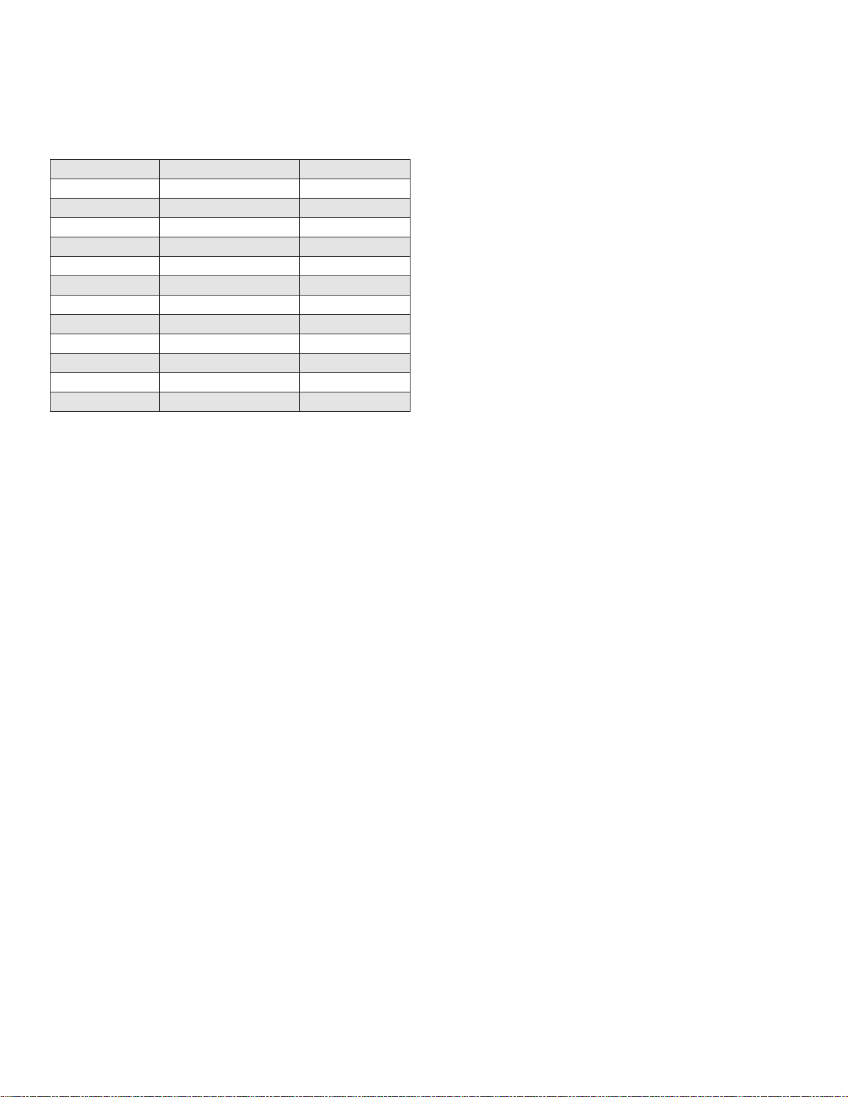
• Fuel Conversion Kits (See Table Below)
Model Description Kit Number
ELX-400 LP to NG Conversion Kit 7550P-200
ELX-400 NG to LP Conversion Kit 7550P-201
ELX-500 LP to NG Conversion Kit 7550P-202
ELX-500 NG to LP Conversion Kit 7550P-203
ELX-650 LP to NG Conversion Kit 7550P-204
ELX-650 NG to LP Conversion Kit 7550P-205
ELX-800 LP to NG Conversion Kit 7550P-206
ELX-800 NG to LP Conversion Kit 7550P-207
ELX-1000 LP to NG Conversion Kit 7550P-314
ELX-1000 NG to LP Conversion Kit 7550P-208
ELX-1500 LP to NG Conversion Kit 7550P-309
ELX-1500 NG to LP Conversion Kit 7550P-310
lp-666 Rev. 003 Rel. 004 Date 9.3.20
Page 9
Part 3 - Prepare the Boiler
CAUTION
WARNING
!
WARNING
!
WARNING
!
CAUTION
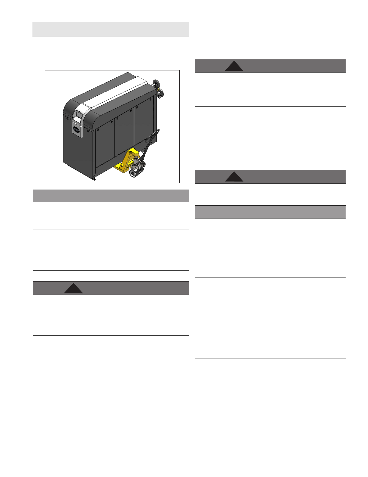
Remove all sides of the shipping crate to allow the boiler to be moved
into its installation location. The boiler is heavy. At least two individuals
and special equipment (pallet jack, forklift, etc.) are needed to properly
handle the boiler. If surface ooring is rough, take care not to damage
the boiler when moving it into position.
9
• Never close existing ventilation openings
• Ensure a minimum 1” clearance around hot water and
exhaust vent pipes
NOTE: To prevent condensing in the fan, it is recommended to
avoid prolonged exposure to temperatures below 45oF
This boiler has a condensate disposal system that may freeze
if exposed to sustained temperatures below 32oF. Precautions
should be taken to protect the condensate trap and drain lines
from sustained freezing conditions. Failure to take precautions
could result in property damage, severe personal injury, or death.
2. Check for nearby connections to:
• System water piping
• Venting connections
• Gas supply piping
• Electrical power
• Condensate drain
3. Check area around boiler. Remove any combustible materials,
gasoline, and other ammable liquids.
Figure 1 - Moving the ELX - 1500 - 2000 Models Shown
COLD WEATHER HANDLING - If the boiler has been stored in a very
cold location (BELOW 0
the components come to room temperature. Failure to do so could
result in damage to the boiler.
Carefully consider installation when determining boiler location.
Please read the entire manual before attempting installation. Failure
to properly take factors such as boiler venting, piping, condensate
removal, and wiring into account before installation could result in
wasted time, money, and possible property damage and personal
injury.
o
F) before installation, handle with care until
A. Locating the Boiler
DO NOT INSTALL the Elite XL OUTDOORS without an optional
Outdoor Installation Kit. Follow the instructions included with
the optional Outdoor Installation Kit when installing the boiler
outdoors. Installing the boiler outdoors without an optional Outdoor
Installation Kit WILL VOID the warranty, and could result in property
damage, severe personal injury, or death.
Incorrect ambient conditions can lead to damage to the heating
system and put safe operation at risk. Ensure that the installation
location adheres to the information included in this manual. Failure
to do so could result in property damage, serious personal injury, or
death. Failure of boiler or components due to incorrect operating
conditions IS NOT covered by product warranty.
This boiler must be installed upright in the vertical position as
described in this manual. DO NOT attempt to install this boiler in any
other orientation. Doing so will result in improper boiler operation
and property damage, and could result in serious personal injury or
death.
1. Installation Area (Mechanical Room) Operating Conditions
• Ensure ambient temperatures are higher than 32oF / 0oC
• Prevent the air from becoming contaminated by the products,
places, and conditions listed in this manual
• Avoid continuously high levels of humidity
Failure to keep the boiler area clear and free of combustible
materials, liquids, and vapors can result in substantial property
damage, severe personal injury, or death.
High heat sources (generating heat 100oF / 37oC or greater, such
as boiler ue pipes, space heaters, etc.) may damage plastic
components of the boiler as well as plastic vent pipe materials.
Such damages ARE NOT covered by warranty. It is recommended
to keep a minimum clearance of 8” from high heat sources. Observe
heat source manufacturer instructions, as well as local, state,
provincial, and national codes, laws, regulations, and ordinances
when installing this boiler and related components near high heat
sources.
The service life of the boiler’s exposed metallic surfaces, such as
the casing, as well as internal surfaces, such as the heat exchanger,
are directly inuenced by proximity to damp and salty marine
environments. In such areas higher concentration levels of
chlorides from sea spray coupled with relative humidity can lead
to degradation of boiler components. In these environments,
boilers must not be installed using direct vent systems which draw
outdoor air for combustion. Such boilers must be installed using
room air for combustion. Indoor air will have a much lower relative
humidity, and hence potential corrosion will be minimized.
Failure of the boiler or components due to incorrect operating
conditions IS NOT covered by product warranty.
4. Gas control system components must be protected from dripping
water during operation and service.
5. If the boiler is to replace an existing boiler, check for and correct
any existing system problems, such as:
• System leaks
• Location that could cause the system and boiler to freeze
and leak
• Incorrectly sized expansion tank
6. Clean and ush system when reinstalling a boiler.
NOTE: When installing in a minimum clearance location, it may
not be possible to read or view some product labeling. It is
recommended to make note of the boiler model and serial number.
lp-666 Rev. 003 Rel. 004 Date 9.3.20
Page 10
10
WARNING
!
WARNING
!
CAUTION
!
WARNING
!
Use extreme care not to drop the boiler or cause bodily injury
while lifting the boiler. Failure to follow these instructions could
result in property damage, severe personal injury, or death.
B. Flooring
400 - 1000 Models ONLY are approved for installation on
combustible ooring, but must never be installed on carpeting.
1500 - 2000 MODELS ARE NOT APPROVED FOR INSTALLATION
ON COMBUSTIBLE FLOORING. Failure to follow these instructions
could result in re, property damage, severe personal injury, or
death.
Ensure that the oor and structure of the installation location
are sucient to support the full installed weight of the boiler,
including water content of the heat exchanger and related piping.
Failure to ensure the oor and structure of the installation location
are structurally sound before installation of the boiler can result
in structural failure, substantial property damage, severe personal
injury, or death.
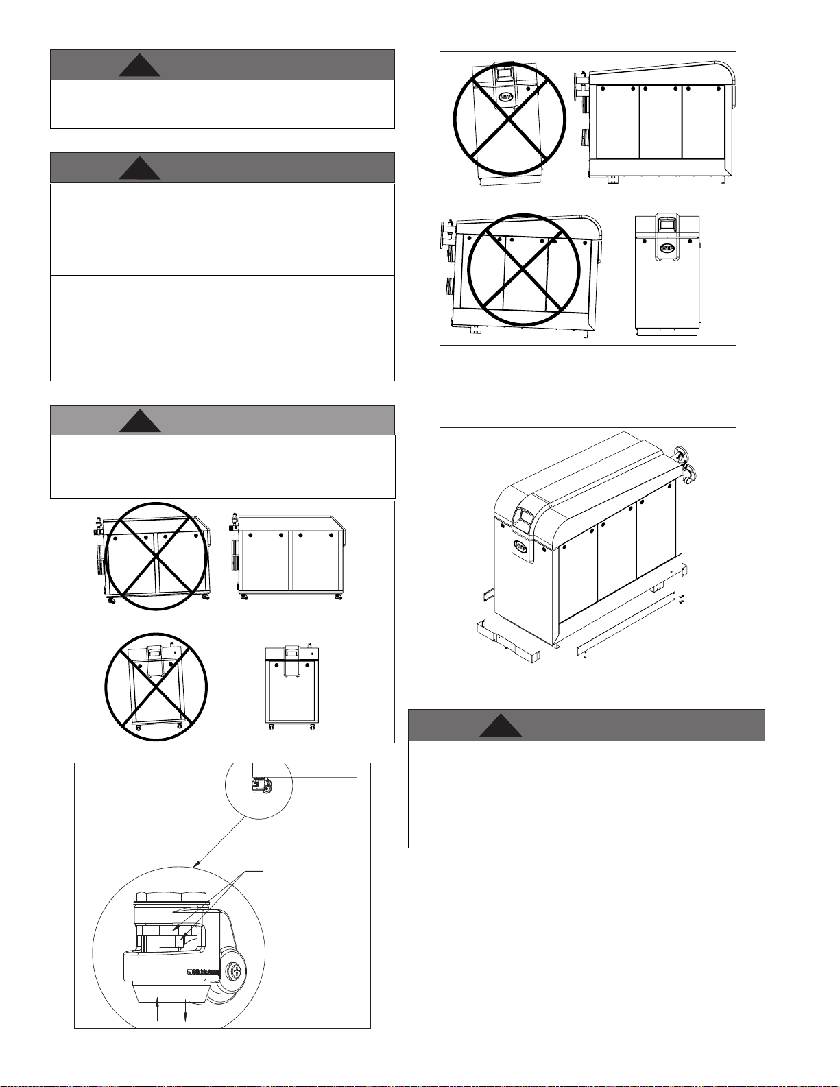
C. Leveling
In order for the condensate to properly ow out of the collection
system, the area where you locate the boiler must be level.
Location must also fully support the weight of the lled boiler. See
Figures 2 - 4.
INCORRECT
Figure 4 - Leveling - 1500 - 2000 Models
1500 - 2000 Models ONLY - After the boiler has been installed level
in the nal location the decorative skirts may be installed. These can
be found in the boiler cabinet. Use the included bolts to install the
front skirt (1) before proceeding to the side skirts (2). See Figure 5.
CORRECT
INCORRECT CORRECT
Figure 2 - Leveling - 400 - 1000 Models
TURN WHEEL TO THE
RIGHT TO LOWER
RUBBER FOOT
TURN WHEEL
TO THE LEFT TO RAISE
RUBBER FOOT
RAISE
Figure 3 - Caster Wheel Adjustment - 400 - 1000 Models ONLY
LOWER
LP-517-W
01/24/19
LP-666-R
01/03/19
2
1
Figure 5 - 1500 - 2000 Models - Installing Decorative Skirts
D. Clearances for Service Access
The space must be provided with combustion / ventilation air
openings correctly sized for all other appliances located in the same
space as the boiler. The boiler cover must be securely fastened to
prevent the boiler from drawing air from the boiler room. This is
particularly important if the boiler is in a room with other appliances.
Failure to comply with the above warnings could result in substantial
property damage, severe personal injury, or death.
NOTE: If you do not provide the minimum clearances shown in Figure
6 it might not be possible to service the boiler without removing it
from the space.
NOTE: A combustible door or removable panel is acceptable front
clearance.
NOTE: In multiple boiler installations, ensure an 18” minimum
clearance is maintained between boilers.
lp-666 Rev. 003 Rel. 004 Date 9.3.20
Page 11
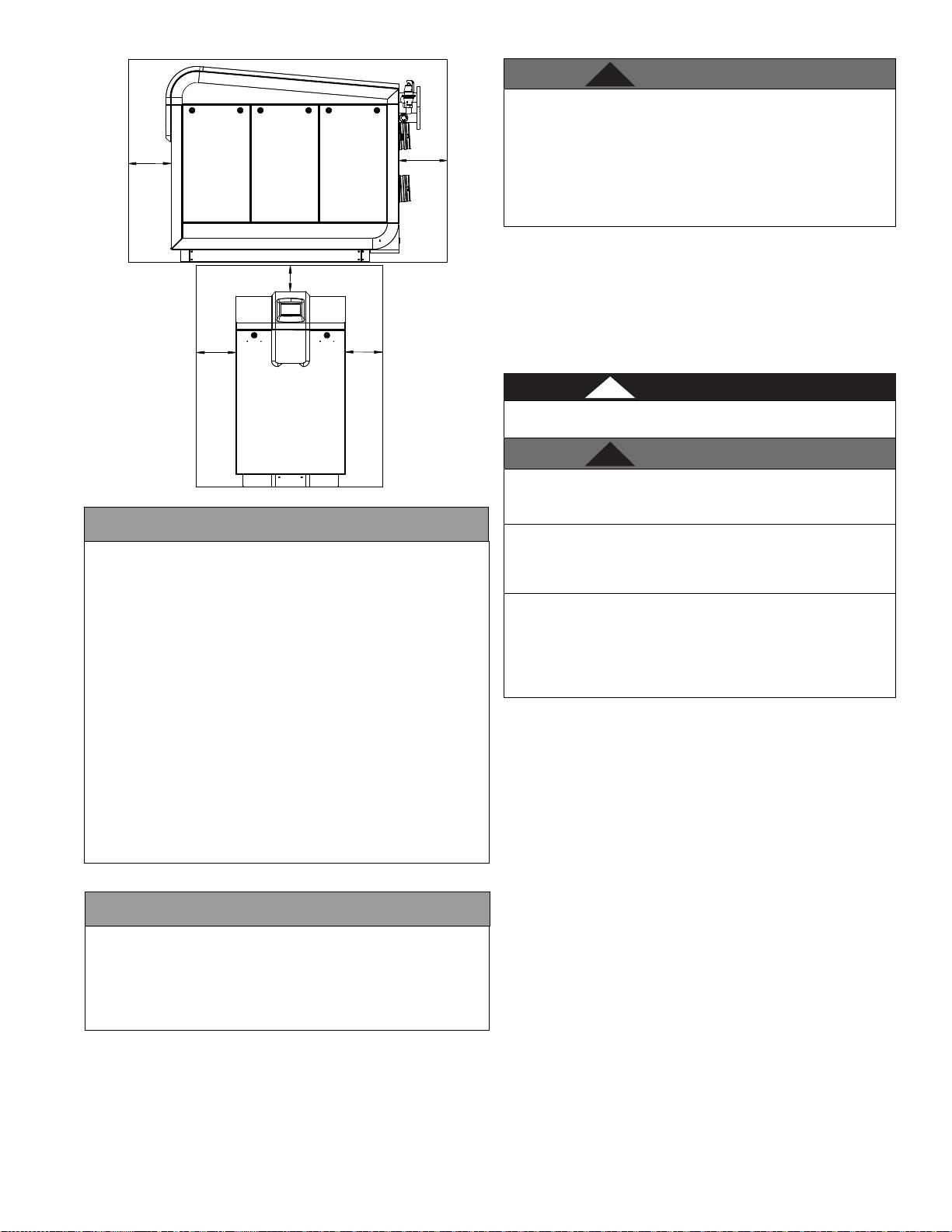
24"
CAUTION
CAUTION
WARNING
!
DANGER
!
WARNING
!
6"
18"
Figure 6 - Recommended Service Clearances
All boilers eventually leak. Locate the boiler where any leakage from
the relief valve, related piping, tank, or connections will not result
in damage to surrounding areas or lower oors of the building.
Any boiler should be installed in such a manner that if it should
leak the resulting ow of water will not cause damage to the area
in which it is installed. If the boiler is installed in a location where
a leak could cause damage, it is required to provide containment
measures. Such measures include but are not limited to: a properly
sized drain pan installed beneath the boiler and piped to an open
drain line, or installing the boiler on a concrete oor pitched to a free
owing drain. Failure to provide containment measures is the sole
responsibility of the owner and/or installer. Leakage damages ARE
NOT covered by warranty.
In addition, water leak detection devices and automatic water shuto
valves are readily available at plumbing supply houses. IT IS HIGHLY
RECOMMENDED BY THE MANUFACTURER TO INSTALL WATER LEAK
DETECTION DEVICES AND AUTOMATIC SHUTOFF VALVES IN ANY
BOILER INSTALLATION WHERE A LEAKAGE OF WATER COULD RESULT
IN PROPERTY DAMAGES.
24”
24"
LP-666-M
10/31/18
E. Residential Garage and Closet Installations
Check with your local Authority Having Jurisdiction for requirements
when installing the boiler in a garage or closet. Please read the
entire manual before attempting installation. Failure to properly take
factors such as venting, piping, condensate removal, and wiring into
account before installation could result in wasted time, money, and
possible property damage and personal injury.
Precautions
If the boiler is located in a residential garage, per ANSI Z223.1:
• Install the boiler burner and ignition devices a minimum of 18”
above the oor of the garage. This will ensure the burner and
ignition devices are well o the oor.
• When raising the boiler ensure the entire bottom and fully
lled weight of the boiler are fully supported.
• Locate or protect the boiler so it cannot be damaged by a
moving vehicle.
11
The space must be provided with correctly sized combustion/
ventilation air openings for all other appliances located in the
space with the boiler. For power venting installations using room
air for combustion, refer to the venting section, this manual, for
descriptions of conned and unconned spaces. Do not install
the boiler in an attic. Failure to comply with these warnings could
result in substantial property damage, severe personal injury, or
death.
F. Exhaust Vent and Intake Pipe
The boiler is rated ANSI Z21.13 Category IV (pressurized vent, likely
to form condensate in the vent) and requires a special vent system
designed for pressurized venting.
NOTE: The venting options described here (and further detailed
in the Venting section, this manual) are the lone venting options
approved for this boiler. Failure to vent the boiler in accordance
with the provided venting instructions will void the warranty.
Failure to vent the boiler properly will result in serious personal
injury or death.
Do not attempt to vent this boiler by any means other than those
described in this manual. Doing so will void the warranty and may
result in severe personal injury or death.
The exhaust discharged by this boiler may be very hot. Avoid
touching or other direct contact with the exhaust gases of the vent
termination assembly. Doing so could result in severe personal
injury or death.
Vents must be properly supported. Boiler exhaust and intake
connections are not designed to carry heavy weight. Vent support
brackets must be within 1’ of the boiler and the balance at 4’
intervals. Boiler must be readily accessible for visual inspection
for rst 3’ from the boiler. Failure to properly support vents could
result in property damage, severe personal injury, or death.
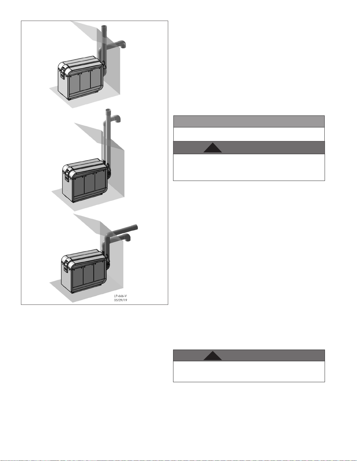
1. Direct Vent of Exhaust and Intake
If installing a direct vent option, combustion air must be drawn
from the outdoors directly into the boiler intake and exhaust must
terminate outdoors. There are three basic direct vent options
detailed in this manual: 1. Side Wall Venting, 2. Roof Venting, and 3.
Unbalanced Venting.
Be sure to locate the boiler such that the exhaust vent and intake
piping can be routed through the building and properly terminated.
Dierent vent terminals can be used to simplify and eliminate
multiple penetrations in the building structure (see Optional
Equipment in Venting Section). The exhaust vent and intake piping
lengths, routing, and termination methods must all comply with
the methods and limits given in the Venting Section, this manual.
When installing a combustion air intake from outdoors, care must
be taken to utilize uncontaminated combustion air. To prevent
combustion air contamination, see Table 1.
lp-666 Rev. 003 Rel. 004 Date 9.3.20
Page 12
12
CAUTION
WARNING
!
WARNING
!
Conned space is space with volume less than 50 cubic feet per
1,000 BTU/hr (4.8 cubic meters per kW) of the total input rating of
all fuel-burning appliances installed in that space. Rooms connected
directly to this space through openings not furnished with doors are
considered part of the space.
When drawing combustion air from inside a conventionally constructed
building to a conned space, such space should be provided with two
permanent openings: one located 6” (15 cm) below the space ceiling,
the other 6” (15cm) above the space oor. Each opening should have a
free area of one square inch per 1,000 BTU/hr (22cm2/kW) of the total
input of all appliances in the space, but not less than 100 square inches
(645cm2).
If the conned space is within a building of tight construction, air for
combustion must be obtained from the outdoors as outlined in the
Venting section of this manual.
When drawing combustion air from the outside into the mechanical
room, care must be taken to provide adequate freeze protection.
Failure to provide an adequate supply of fresh combustion air can
cause poisonous ue gases to enter the living space, resulting
in severe personal injury or death. To prevent combustion air
contamination, see Table 1.
Figure 7 - Direct Vent Examples
2. Power Venting, Indoor Combustion Air in Conned or
Unconned Space
This boiler requires fresh, uncontaminated air for safe operation and
must be installed in a mechanical room where there is adequate
combustion and ventilating air. NOTE: To prevent combustion air
contamination, see Table 1.
Combustion air from the indoor space can be used if the space has
adequate area or when air is provided through a duct or louver to
supply sucient combustion air based on the boiler input. Never
obstruct the supply of combustion air to the boiler. If the boiler is
installed in areas where indoor air is contaminated (see Table 1) it
is imperative that the boiler be installed as direct vent so that all
combustion air is taken directly from the outdoors into the boiler
intake connection.
Unconned space is space with volume greater than 50 cubic feet
per 1,000 BTU/hr (4.8 cubic meters per kW) of the total input rating of
all fuel-burning appliances installed in that space. Rooms connected
directly to this space through openings not furnished with doors are
considered part of the space. See Venting Section for details.
G. Carbon Monoxide Detectors
In the Commonwealth of Massachusetts and As Required by State
and Local Codes:
Installation of Carbon Monoxide Detectors: At the time of installation
or replacement of the vented gas fueled appliance, the installing
plumber or gas tter shall observe that a hard wired carbon monoxide
detector with an alarm and battery back-up is installed on the oor
level where the gas appliance is installed, unless the appliance is
located in a detached, uninhabitable structure separate from the
dwelling, building, or structure used in whole or in part for residential
purposes.
In addition, the installing plumber or gas tter shall observe that a hard
wired carbon monoxide detector with an alarm and battery back-up is
installed on each additional level of the dwelling, building, or structure
served by the vented gas appliance. It shall be the responsibility of the
property owner to secure the service of qualied licensed professionals
for the installation of hard wired carbon monoxide detectors.
a. In the event that the vented gas fueled appliance is installed in a
crawl space or attic, the hard wired carbon monoxide detector with
alarm and battery back-up shall be installed on the next adjacent
oor level.
b. In the event that these requirements cannot be met at the time of
completion of installation, the owner shall have a period of thirty (30)
days to comply with the above requirements; provided, however,
that during said thirty (30) day period, a battery operated carbon
monoxide detector with an alarm shall be installed.
Do not attempt to vent this appliance by any means other than those
described in this manual. Doing so will void the warranty and may
result in severe personal injury or death.
Approved Carbon Monoxide Detectors: Each carbon monoxide
detector as required in accordance with the above provisions shall
comply with NFPA 70 and be ANSI/UL 2034 listed and IAS certied.
H. Prevent Combustion Air Contamination
Install intake air piping for the boiler as described in the Venting
Section, this manual. Do not terminate exhaust in locations that can
allow contamination of intake air.
lp-666 Rev. 003 Rel. 004 Date 9.3.20
Page 13
WARNING
!
Ensure that the intake air will not contain any of the contaminants
WARNING
!
DANGER
!
WARNING
!
in Table 1. Contaminated air will damage the boiler, resulting in
possible substantial property damage, severe personal injury, or
death. For example, do not pipe intake air near a swimming pool or
laundry facilities. These areas always contain contaminants.
Products to Avoid
Spray cans containing
uorocarbons
Permanent wave solutions Swimming pools
Chlorinated waxes / cleaners Metal fabrication plants
Chlorine-based swimming pool
chemicals
Calcium chloride used for thawing Refrigeration repair shops
Sodium chloride used for water
softening
Refrigerant leaks Auto body shops
Paint or varnish removers Plastic manufacturing plants
Hydrochloric or Muriatic acid
Cements and glues New building construction
Antistatic fabric softeners used in
clothes dryers
Chlorine-type bleaches, laundry
detergents, and cleaning solvents
Adhesives used to fasten building
products
Table 1 - Products and Areas Likely to Have Contaminants
NOTE: DAMAGE TO THE BOILER CAUSED BY EXPOSURE TO
CORROSIVE VAPORS IS NOT COVERED BY WARRANTY. (Refer to
the limited warranty for complete terms and conditions.)
Areas Likely to Have
Contaminants
Dry cleaning / laundry areas
and establishments
Beauty shops
Photo processing plants
Furniture renishing areas
and establishments
Remodeling areas
Garages and workshops
I. Removing a Boiler from a Common Vent System
Do not install the boiler into a common vent with any other
appliance. This will cause ue gas spillage or appliance malfunction,
resulting in possible substantial property damage, severe personal
injury, or death.
Failure to follow all instructions can result in ue gas spillage and
carbon monoxide emissions, causing severe personal injury or death.
When removing an existing boiler, follow the steps below.
1. Seal any unused openings in the common venting system.
2. Visually inspect the venting system for proper size and horizontal
pitch to determine if there is blockage, leakage, corrosion, or other
deciencies that could cause an unsafe condition.
3. If practical, close all building doors, windows, and doors between the
space in which the boiler remains connected to the common venting
system and other spaces in the building. Turn on clothes dryers and
any appliances not connected to the common venting system. Turn
on any exhaust fans, such as range hoods and bathroom exhausts,
at maximum speed. Do not operate a summer exhaust fan. Close all
replace dampers.
4. Place in operation the appliance being inspected. Follow the lighting
instructions. Adjust the thermostat so the appliance will operate
continuously.
13
5. Test for spillage at the draft hood relief opening after 5 minutes of
main burner operation. Use the ame of a match or candle or smoke
from a cigarette.
6. After it has been determined that each appliance remaining
connected to the common venting system properly vents when
tested as outlined, return doors, windows, exhaust fans, replace
dampers, and any other gas burning appliances to their previous
condition of use.
7. Any improper operation of the common venting system should
be corrected to conform to the National Fuel Gas Code, ANSI Z223.1.
When resizing any portion of the common venting system, the
system should approach the minimum size as determined using the
appropriate tables in Appendix G of ANSI Z223.1.
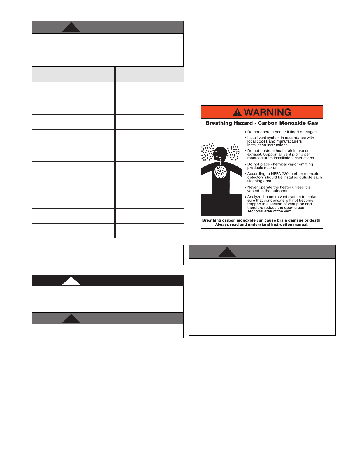
Figure 8 - CO Warning Label
J. Water Chemistry Requirements*
Chemical imbalance of the water supply may aect eciency
and cause severe damage to the appliance and associated
equipment. It is important that the water chemistry on both the
domestic hot water and central heating sides are checked before
installing the appliance. Water quality must be professionally
analyzed to determine whether it is necessary to treat the water.
Various solutions are available to adjust water quality. Adverse
water quality will aect the reliability of the system. In addition,
operating temperatures above 135oF will accelerate the build-up
of lime scale and possibly shorten appliance service life. Failure of
an appliance due to lime scale build-up, low pH, or other chemical
imbalance IS NOT covered by the warranty.
Closed loop water must be free of corrosive chemicals, sand, dirt,
and other contaminates. It is up to the installer to ensure the water
does not contain corrosive chemicals or elements that can damage
the heat exchanger.
If you suspect that your water is contaminated in any way,
discontinue use of the appliance and contact an authorized
technician or licensed professional.
• Water pH between 6.5 and 8.5
• pH levels below 6.5 can cause an increase in the rate of
corrosion. pH of 8.5 or higher can potentially cause lime
scale build-up.
• Maintain water pH between 6.5 and 8.5. Check with litmus
paper or have it chemically analyzed by a local water treatment company.
• If the pH is not between 6.5 and 8.5, consult a local water
treatment company for solutions.
lp-666 Rev. 003 Rel. 004 Date 9.3.20
Page 14
14
WARNING
!
WARNING
!
• Hardness between 5 and 12 grains (71.3 and 205 mg/L)*
• Hardness levels above the required amounts can lead to
lime scale build-up throughout the system. Water below 5
grains/gallon (71.3 mg/L) may be over softened.
• Consult local water treatment companies for unusually
hard water areas (above the required amounts) or for
other treatment solutions if water is being over softened
(below 5 grains/gallon [71.3 mg/L]).
• Chloride concentration less than 150 ppm (mg/L)
• Do not ll appliance or operate with water containing
chlorides in excess of 150 ppm (mg/L).
• Using chlorinated fresh water should be acceptable as
levels are typically less than 5 ppm (mg/L).
• Do not connect the appliance to directly heat swimming
pool or spa water.
• Total Dissolved Solids (TDS) between 100 and 450 ppm
(mg/L)*
• Total dissolved solids are minerals, salts, metals, and
charged particles that are dissolved in water.
• The greater the amounts of TDS present, the higher the
corrosion potential due to increased conductivity in the
water.
• If using softened water to ll the appliance, it is still
possible to have high TDS. This water can be corrosive.
Consult local water treatment companies for other
treatment solutions to reduce this aect.
*NOTE: The amount of Hardness ppm (mg/L) + TDS ppm (mg/L)
must be less than 450 ppm (mg/L) total. For Example:
WATER CHEMISTRY NOTES:
1. Avoid exposing the heat exchanger water tubes to oxygen to
prevent internal corrosion. System leaks and continuous makeup water will introduce oxygen into the system, increasing the
opportunity for internal corrosion and possibly reducing the life of
the heat exchanger and system components.
2. Leaks in the boiler or piping must be repaired at once to prevent
excessive make-up water. It is recommended to install a water
meter to regularly check the amount of make-up water entering the
system. Make-up water volume should not exceed 5% of the total
system volume per year. When make-up water is added, ensure
chemical additives (glycol, corrosion inhibitors, etc.) are added to
maintain the correct level.
3. Regularly monitoring pH, chlorides, TDS, and hardness levels can
prolong the life of the appliance by reducing mineral scale buildup,
corrosion, and erosion. Mineral buildup in the heat exchanger
reduces heat transfer, overheats the stainless steel heat exchanger,
and causes failure.
4. A corrosion inhibitor approved for use with stainless steel
heat exchangers (comparable to Sentinel X100 or Fernox F1) is
recommended at the correct concentration and in the manner
recommended by the manufacturer.
Elite XL outdoor models are intended for warm weather applications.
DO NOT install the Elite XL outdoors in areas prone to freezing (below
32oF / 0oC). Incorrect ambient conditions can lead to damage to
the heating system and put safe operation at risk. Ensure that the
installation location adheres to the information included in this
manual. Failure to do so could result in property damage, serious
personal injury, or death. Failure of Elite XL or components due to
incorrect operating conditions IS NOT covered by product warranty.
Exhaust vent adaptors are not designed as load-bearing devices,
and must not be used to support exhaust vent piping. All vent pipes
must be properly connected, supported, and the exhaust vent must
be pitched a minimum of 1/4” per foot back to the Elite XL to allow
drainage of condensate. Failure to properly support vent piping
and follow the information in this statement could result in product
damage, severe personal injury, or death.
General Outdoor Installation Guidelines
1. The Elite XL must not be installed outdoors in freezing climates.
Elite XLs installed outdoors must be vented with listed UV-resistant
vent materials per the following instructions and installed with
the optional factory-supplied Outdoor Installation Kit.
2. Keep venting areas free of obstructions, and combustible and
ammable materials. Keep the air intake and exhaust vent
terminations free of obstructions.
3. Do not install directly on the ground. Install on a concrete, brick,
block, or other non-combustible pad.
4. Install unit in a location that avoids opportunities for exhaust gas
recirculation.
5. Clearances around outdoor installations may change over
time. Make sure the growth or trees, shrubs, landscaping, etc. is
properly maintained.
6. Do not install in locations where building runo will spill onto the
unit.
7. Multiple unit installations require at least a 4’ (48 in.) clearance
between exhaust vents.
8. Locate unit at least 3’ (36 in.) away from any overhang.
9. Follow the outdoor kit instructions when locating / venting the
unit.
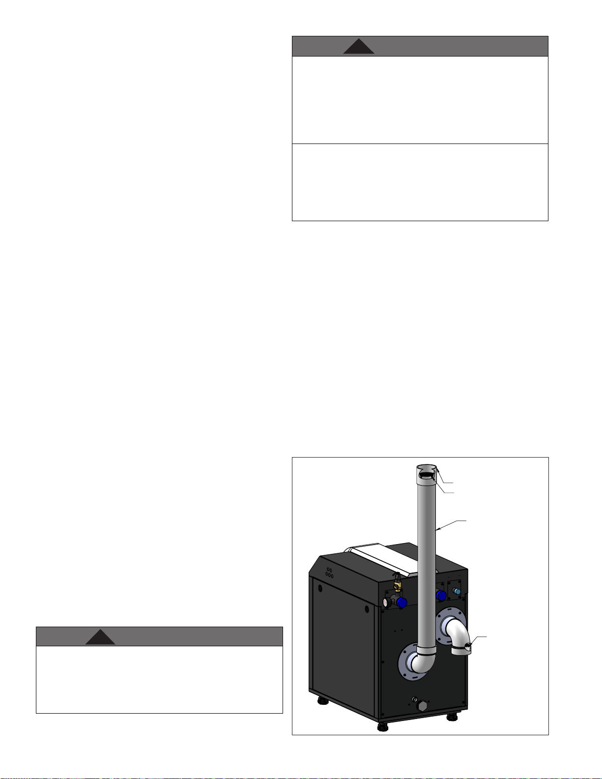
COUPLING
SCREEN
THE VENT MUST TERMINATE
AT LEAST 24" ABOVE THE
TOP OF THE UNIT
K. Outdoor Installations
DO NOT INSTALL the Elite XL OUTDOORS without an optional
Outdoor Installation Kit. Follow the instructions included with
the optional Outdoor Installation Kit when installing the VWH
outdoors. Installing the VWH outdoors without an optional
Outdoor Installation Kit WILL VOID the warranty, and could result
in property damage, severe personal injury, or death.
lp-666 Rev. 003 Rel. 004 Date 9.3.20
Figure 9 - Outdoor Venting Installation
SCREEN
LP-666-AB
06/30/20
Page 15
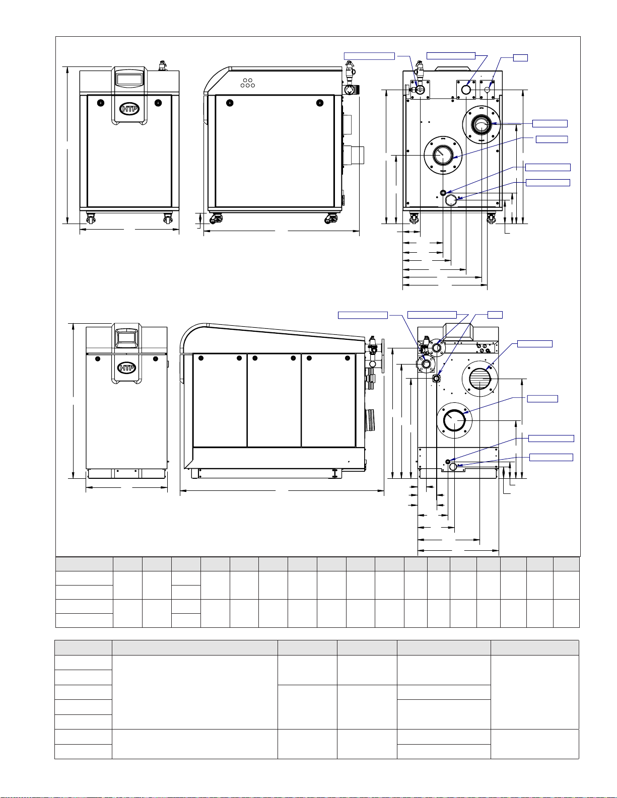
15
ELX-400-1000
A
ELX-1500-2000
B
R
C
WATER SUPPLY
WATER SUPPLY
E
D
F
WATER RETURN
G
H
J
K
L
M
WATER RETURN
GAS
GAS
Q
P
O
N
AIR INTAKE
EXHAUST
CONDENSATE
2" CLEANOUT
AIR INTAKE
R
Q
P
O
LP-666-P
04/06/20
EXHAUST
CONDENSATE
2" CLEANOUT
A
B
C
F
E
G
H
J
D
K
L
M
N
MODEL # A B C D E F G H J K L M N O P Q R
ELX400-500
ELX650-1000 56.5
ELX1500
ELX2000 80.0
41.0 26.0
60.8 31.8
40.7
17.9 35.0 4.1 10.1 10.5 12.6 16.1 20.5 22.0 6.1 8.1 25.8 35.0 2.8*
67.5
39.2 44.8 51.2 3.4 7.4 7.5 11.9 14.4 24.4 31.8 4.6 6.5 22.7 39.1
Figure 10 - ELX Specications and Dimensions - NOTE: All Dimensions Are Approximate - *FOR REFERENCE ONLY
Model Water Connection Vent Size Air Intake Gas Connection Condensate
400
500
650
2" NPT
800
1000
1500
2000 2”
Table 2 - ELX Adapter Dimensions and Specications
2 1/2” Flange 8” 8”
4" 4" 1"
6" 6"
1-1/4"
1-1/2”
1"
3/4" PVC
1” PVC
lp-666 Rev. 003 Rel. 004 Date 9.3.20
Page 16
16
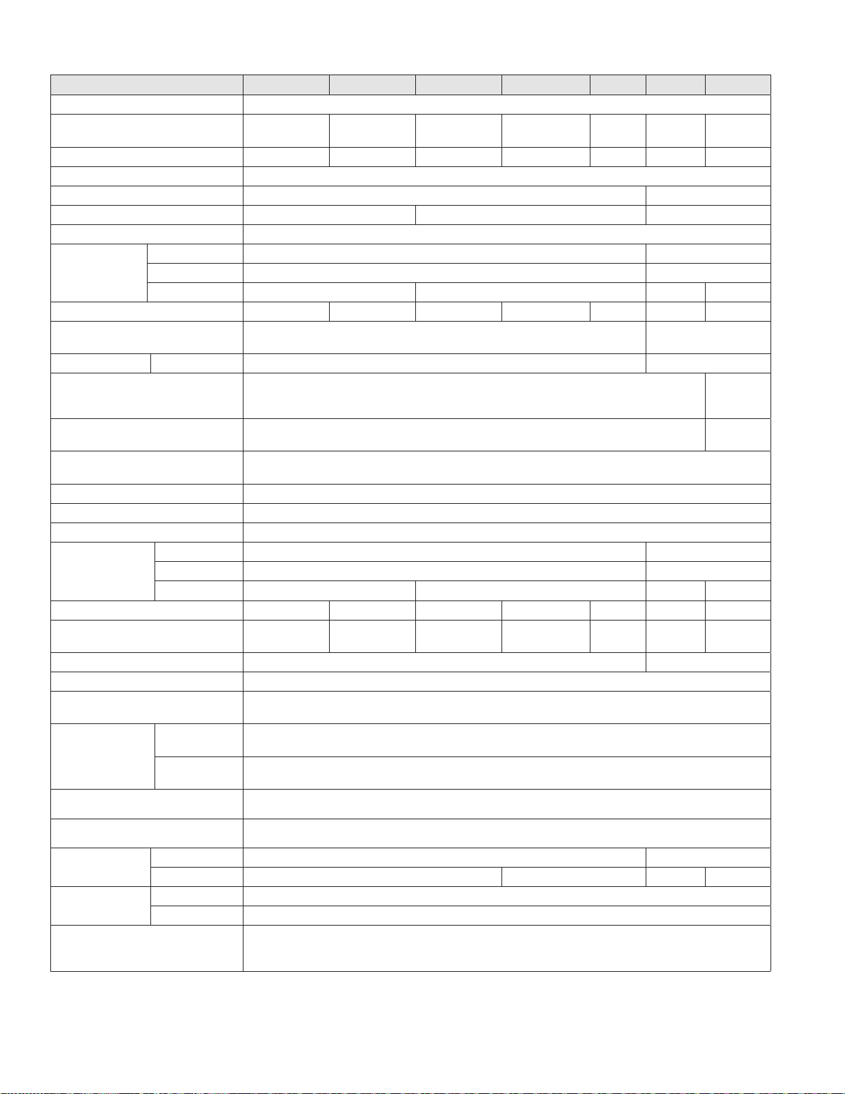
L. Technical Specications
Model 400 500 650 800 1000 1500 2000
Installation Indoor or Outdoor (with Optional Kit), Floor Standing, Fully Condensing
Minimum / Maximum Input (Btu/Hr) 39,900 / 399,000 50,000 / 500,000 65,000 / 650,000 80,000 / 800,000
Heating Capacity (MBH) 387 485 630 776 970 1,455 1,940
Flue System Category IV, Sealed Combustion Direct Vent, Power Vent
Minimum Combined Vent Run 10 feet 15 feet
Maximum Combined Vent Run 4” (125 feet) 6” (125 feet) 8” (150 feet)
Approved Exhaust Vent Materials PVC, CPVC, PP, Stainless Steel
Packaging
Dimensions
(in Inches)
Shipping Weight (lbs) 538 545 680 700 745 1400 1750
Gas Supply Pressure 3.5” to 14” WC (NG or LP)
Manifold Pressure Min / Max NG/LP: -0.08” WC NG: -0.07” WC
Power Supply 120V 60 Hz, 20A
Customer Connection Board Fuse
Amperage Ratings
General Operating Conditions
Ignition System Direct Electronic Spark Ignition / Flame Rectication
Burner System Premixed Fuel Modulation / Stainless Steel Burner
Gas Valve System Pneumatic Gas Valve
Dimensions
(in Inches)
Boiler Water Content (Gallons) 3.8 4.3 5.6 6.6 8.1 12.9 16.25
Minimum Flow Rate @ 20oF ∆T at
Low Fire (GPM)
Flow Switch Activation (GPM) 4 9
Boiler Setpoint Temperature Range 50 – 190oF / 32 - 190oF (with Outdoor Reset Curve)
DHW Indirect Setpoint Temperature
Range
Water Pressure
(PSI)
W 32.25 43.25
H 49.625 64.25
D 48 64 76 86
2 Amps 5 Amps
Product Approvals and Requirements: ANSI Z21.13 / CSA 4.9, CSD-1 ASME Code
W 26 31.8
H 41 60.8
D 40.7 56.5 66.5 79
4 5 6.5 8 10 15 20
Heat Exchanger
MAWP
Pressure Relief
Valve
Minimum Ambient Temperature: Greater than 32oF (0oC)
70 – 185oF
160
50
100,000 /
1,000,000
150,000 /
1,500,000
3.5” to 10.5” WC (NG
ONLY)
WYE, 60Hz,
200,000 /
2,000,000
208/3PH
15A/Leg
Control Panel 7” Full Color Touch Screen
Main Controller 928 SIT Control
Connection Sizes
Materials
Safety Devices
Table 3 - Technical Specications
Supply / Return 2” NPT 2 1/2” Flange
Gas Inlet 1” NPT 1 1/4” NPT 1 1/2” NPT 2” NPT
Cabinet Powder Coated Galvaneal Steel
Heat Exchanger 316L Stainless Steel Water Tube
lp-666 Rev. 003 Rel. 004 Date 9.3.20
Flame Rectier Probe, Dual Water Supply Temperature Sensor / High Limit (210oF), Freeze Protection, Condensate
Trap with Float, Dual Flue Sensor (210oF), Blocked Vent Pressure Switch, Internal UL 353 Approved Low Water
Cut-O (LWCO), High Resolution Flow Switch
Page 17
Part 4 - Piping
WARNING
!
CAUTION
CAUTION
WARNING
!
WARNING
!
CAUTION
CAUTION
WARNING
!
Failure to follow the instructions in this section WILL VOID the
warranty and may result in property damage, severe personal
injury, or death.
Dielectric unions or galvanized steel ttings must not be used in a
system with this boiler. Doing so WILL VOID the warranty. Use only
copper, brass, or stainless steel ttings. Teon thread sealant must
be used on all connections.
Plumbing of this product should only be done by a qualied, licensed
plumber in accordance with all local plumbing codes. The boiler
may be connected to an indirect water heater to supply domestic
hot water. HTP oers indirect water heaters in either stainless steel
or glass-lined construction.
A. General Plumbing Information
The building piping system must meet or exceed the piping
requirements in this manual.
The control module uses temperature sensors to provide both
high limit protection and modulating temperature control. The
control module also provides low water protection by sensing the
water level in the heat exchanger. Some codes/jurisdictions may
require additional external controls.
Use two wrenches when tightening water piping at boiler. Use one
wrench to prevent the boiler return or supply line from turning.
Failure to prevent piping connections from turning could cause
damage to boiler components.
NOTE: The addition of a high temperature limiting device is
important if the boiler is used to indirectly heat domestic hot water.
B. Relief Valve
Connect discharge piping to a safe disposal location by following
these guidelines.
Do not thread a cap or plug into the relief valve or relief valve line
under any circumstances! Explosion and property damage, serious
injury, or death may result.
RE-INSPECTION OF RELIEF VALVES: Valves should be inspected
AT LEAST ONCE EVERY THREE YEARS, and replaced if necessary,
by a licensed plumbing contractor or qualied service technician
to ensure that the product has not been aected by corrosive
water conditions and to ensure that the valve and discharge line
have not been altered or tampered with illegally. Certain naturally
occuring conditions may corrode the valve and its components
over time, rendering the valve inoperative. Such conditions can
only be detected if the valve and its components are physically
removed and inspected. Do not attempt to conduct an
inspection on your own. Contact your plumbing contractor for a
re-inspection to assure continued safety.
FAILURE TO RE-INSPECT THE RELIEF VALVE AS DIRECTED
COULD RESULT IN UNSAFE TEMPERATURE AND/OR PRESSURE
BUILD-UP WHICH CAN RESULT IN PROPERTY DAMAGE,
SERIOUS PERSONAL INJURY, OR DEATH.
17
To avoid water damage or scalding due to relief valve operation:
• Discharge line must be connected to relief valve outlet and
run to a safe place of disposal. Terminate the discharge line
in a manner that will prevent possibility of severe burns or
property damage should the relief valve discharge.
• Discharge line must be as short as possible and the same
size as the valve discharge connection throughout its entire
length.
• Discharge line must pitch downward from the valve and
terminate at least 6” above the oor drain, making discharge
clearly visible.
• The discharge line shall terminate plain, not threaded, with
a material serviceable for temperatures of 375oF or greater.
• Do not pipe discharge to any location where freezing could
occur.
• No valve may be installed between the relief valve and boiler
or in the discharge line. Do not plug or place any obstruction
in the discharge line.
• Test the operation of the relief valve after lling and
pressurizing the system by lifting the lever. Make sure the
valve discharges freely. If the valve fails to operate correctly,
immediately replace with a new properly rated relief valve.
• Test relief valve at least once annually to ensure the waterway
is clear. If valve does not operate, turn the boiler “o” and call
a plumber immediately.
• Take care whenever operating relief valve to avoid scalding
injury or property damage.
FAILURE TO COMPLY WITH THE ABOVE GUIDELINES COULD RESULT
IN FAILURE OF RELIEF VALVE OPERATION, RESULTING IN POSSIBILITY
OF SUBSTANTIAL PROPERTY DAMAGE, SEVERE PERSONAL INJURY,
OR DEATH.
C. Backow Preventer
Use a backow preventer specically designed for hydronic boiler
installations. This valve should be installed on the cold water ll supply
line per local codes.
All piping methods in this manual use primary / secondary
connections to the boiler loop. This is to avoid the possibility of
inadequate ow through the boiler. For other piping methods,
consult your local HTP representative or refer to Applications in this
manual.
D. Expansion Tank
Expansion Tank and Make-Up Water
1. Ensure that the expansion tank is sized to correctly handle boiler
and system water volume and temperature.
Expansion tanks must be sized according to total system volume.
This includes all length of pipe, all xtures, boilers, etc. Failure to
properly size for system expansion could result in wasted time,
money, possible property damage, serious injury, or death.
Undersized expansion tanks cause system water to be lost from the
relief valve, causing make-up water to be added. Eventual boiler
failure can result due to excessive make-up water addition. SUCH
FAILURE IS NOT COVERED BY WARRANTY.
DO NOT install automatic air vents on closed type expansion tank
systems. Air must remain in the system and return to the tank to
provide an air cushion. An automatic air vent would cause air to leave
the system, resulting in improper operation of the expansion tank.
lp-666 Rev. 003 Rel. 004 Date 9.3.20
Page 18

18
CAUTION
CAUTION
Model Heat Exchanger Volume (Gallons)
400 3.8
500 4.3
650 5.6
800 6.6
1000 8.1
1500 12.9
2000 16.25
Table 4 - Heat Exchanger Volume
2. The expansion tank must be located as shown in Applications, this
manual, or following recognized design methods. See expansion tank
manufacturer’s instructions for details.
3. Connect the expansion tank to the air separator only if the separator
is on the suction side of the circulator. Always install the system ll
connection at the same point as the expansion tank connection to the
system.
4. Most chilled water systems are piped using a closed type expansion
tank.
E. Circulators
Never use dielectric unions or galvanized steel ttings when
connecting to a stainless steel storage tank or boiler. Failure to
follow this instruction can lead to premature failure of the boiler
system. Such failures ARE NOT covered by warranty.
The boiler should not be operated as a potable hot water heater.
The boiler should not be used as a direct hot water heating
device.
DO NOT use the boiler circulator in any location other than the
ones shown in this manual. The boiler circulator location is selected
to ensure adequate ow through the boiler. Failure to comply with
this caution could result in unreliable performance and nuisance
shutdowns from insucient ow.
SIZING SPACE HEAT SYSTEM PIPING
Size the piping and components in the space heating system using
recognized design methods.
F. Hydronic Piping with Circulators, Zone Valves, and
Multiple Boilers
The boiler is designed to function in a closed loop hydronic system.
The included temperature and pressure gauge allows the user to
monitor system pressure and outlet temperature from the boiler. It is
important to note that the boiler has a minimal amount of pressure
drop that must be calculated when sizing the circulators. Each boiler
installation must have an air elimination device that will remove air
from the system.
Install the boiler so the gas ignition system components are protected
from water (dripping, spraying, etc.). Allow clearance for basic service of
the boiler circulator, valves, and other components. Observe minimum
1” clearance around all uninsulated hot water pipes when openings
around pipes are not protected by non-combustible materials.
On a boiler installed above radiation level, some states and local codes
require a low water cut o device. This is provided standard on the
boiler. Check with local codes for additional requirements. If the boiler
supplies hot water to heating coils in air handler units, ow control
valves or other devices must be installed to prevent gravity circulation
of boiler water in the coils during the cooling cycle. Chilled water
medium must be piped in parallel with the boiler.
Freeze protection for new or existing systems must use glycol
specically formulated for this purpose. This glycol must include
inhibitors that will prevent it from attacking metallic system
components. Make certain that the system uid is checked for the
correct glycol concentration and inhibitor level. The system should be
tested at least once a year and as recommended by the producer of the
glycol solution. Allowance should be made for the expansion of the
glycol solution in the system piping. Example: 50% by volume glycol
solution expands 4.8% in volume for the temperature increase from
32oF to 180oF, while water expands 3% over the same temperature rise.
lp-666 Rev. 003 Rel. 004 Date 9.3.20
Page 19
19
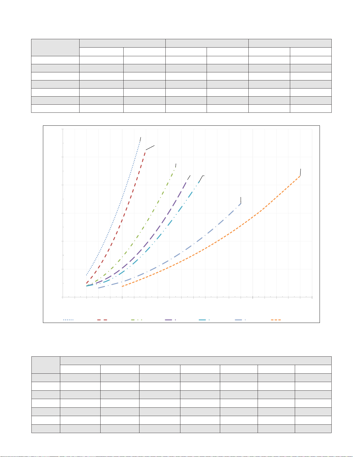
ELX-400 ELX-500 ELX-650 ELX-800 ELX-1000 ELX-1500 ELX-2000
G. Circulator Sizing
In addition, the boiler heat exchanger has a minimum total water ow rate that must be taken into account when sizing the circulator.
Pressure drops are listed in the table below.
Model
400 39 12.0 26 7.2 19 4.0
500 48 11.4 32 5.4 24 3.2
650 63 11.5 42 6.2 31 4.0
800 77 12 52 6 39 3
1000 96 14.0 64 7 48 4.7
1500 146 16 97 7.6 73 4.7
2000 194 21 129 11.5 97 6.7
Table 5 - Pressure Drop at Various Temperature Rises
GPM Ft / Hd GPM Ft / Hd GPM Ft / Hd
The boiler heat exchanger does have a pressure drop which must be considered in system design.
30
20oF 30oF 40oF
ELX-400
ELX-500
25
20
15
10
Pressure Loss (Feet of Head) +/- 10%
5
0
0 10 20 30 40 50 60 70 80 90 100 110 120 130 140 150 160 170 180 190 200 210
ELX-650
ELX-800
Flow Rate (GPM)
ELX-1000
ELX-1500
ELX-2000
Figure 11 - Pressure Drop through the Boiler
The chart below represents the combined ow rates and pipe sizes when using multiple boilers to design the manifold system for the primary
circuit. To size, simply add up the number of boilers and the required ow rates for the system design temperature.
Example: (5) 1000 boilers with a design of 30oF temperature rise with each boiler having an individual ow rate of 64 GPM. To correctly size
the manifold feeding these boilers, you would need a pipe size of 6”.
Model
400 3 3 4 4 5 5 5
500 3 4 4 5 5 5 6
650 4 4 5 5 6 6 6
800 4 5 5 6 6 8 8
1000 4 5 6 6 8 8 8
1500 5 6 8 8 8 10 10
2000 6 6 8 8 10 10 12
Table 6 - Multiple Boiler Manifold Piping - NOTE: Table based on water velocity less than Five (5) feet per second.
2 3 4 5 6 7 8
Number of Units and Recommended Common Header Pipe Sizes in Inches
lp-666 Rev. 003 Rel. 004 Date 9.3.20
Page 20
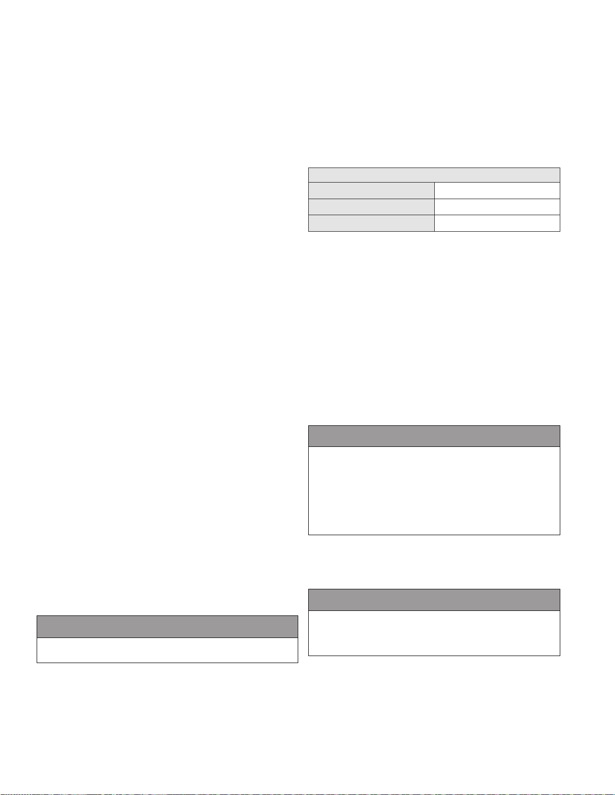
20
CAUTION
CAUTION
CAUTION
H. Check / Control Water Chemistry
NOTE: Boiler failure due to improper water chemistry is not
covered by warranty.
• Water pH between 6.5 and 8.5
• Hardness between 5 and 12 grains (71.3 and 205 mg/L)
• Chloride concentration less than 150 ppm (mg/L)
• Total Dissolved Solids (TDS) between 100 and 450 ppm
(mg/L)
*NOTE: It is recommended to clean the heat exchanger at least once a
year to prevent lime scale buildup. To clean the heat exchanger, follow
the maintenance procedure in this manual.
Clean system to remove sediment*
1. You must thoroughly ush the system (without boiler connected)
to remove sediment. The high-eciency heat exchanger can be
damaged by buildup or corrosion due to sediment.
2. For zoned systems, ush each zone separately through a purge
valve. (If purge valves and isolation valves are not already installed,
install them to properly clean the system.)
3. Flush system until water runs clean and you are sure piping is free
of sediment.
*NOTE: It is recommended you clean heat exchanger at least once a
year to prevent lime scale buildup. Follow the maintenance procedure
to clean the heat exchanger in the Maintenance Section of this manual.
Test/replace freeze protection uid
1. For systems using freeze protection uids, follow uid manufacturer’s
instructions to verify inhibitor level and that other uid characteristics
are satisfactory.
2. Freeze protection uid must be replaced periodically due to
degradation of inhibitors over time. Follow all uid manufacturer
instructions.
I. Plumbing
Piping Components
Heating System Piping
System piping MUST meet the technical pipe requirements listed in
Table 7. Reducing pipe size can restrict ow rate through the boiler,
causing inadvertent short cycling and poor system performance.
Check Valves
Field supplied. Check valves are recommended for installation as
shown in Applications.
Isolation Valves
Field supplied. Full port ball valves are required. Failure to use full port
ball valves could result in a restricted ow rate through the boiler.
Anti-Scald Mixing Valve
Field supplied. An anti-scald mixing valve is recommended when
storing domestic hot water above 115°F.
Steel Flanges
Field supplied. Recommended for unit serviceability.
Pressure Relief Valve
Factory supplied on boiler. The pressure relief valve is sized to ASME
specications. Storage tank may require additional relief valves
depending on local codes.
This boiler should not be operated as a potable hot water heater. It
should not be used as a direct hot water heating device.
Basic steps are listed below that will guide the installation of the boiler.
1. Connect the system return marked “Inlet”.
2. Connect the system supply marked “Outlet”.
3. Install purge and balance valve or shut o valve and drain on system
return to purge air out of each zone.
4. Install a back ow preventer on the cold feed make-up water line.
5. Install a pressure reducing valve on the cold feed make-up water
line (15 PSI nominal on the system return). Check temperature and
pressure gauge when operating. It should read a minimum pressure
of 12 PSI.
6. Install a circulator as shown in piping details (this section). Make
sure the circulator is properly sized for the system and friction loss.
7. Install an expansion tank on the system supply. Consult the tank
manufacturer’s instructions for specic information relating to
expansion tank installation. Size the expansion tank for the required
system volume and capacity.
8. Install an air elimination device on the system supply.
9. The relief valve is installed at the factory. A pipe discharge line
should be installed to discharge 6” above the drain in the event of
pressure relief. The pipe size must be the same size as the relief valve
outlet. NEVER BLOCK THE OUTLET OF THE SAFETY RELIEF VALVE.
Minimum Water Pipe Size
Model Size
400 - 1000 2” NPT
1500 - 2000 2 1/2” Flange
Table 7 - Minimum Pipe Size
J. Fill and Purge Heating System
• Attach the hose to balance and purge hose connector or
drain valve and run hose to nearest drain.
• Close the other side of the balance and purge valve or the
shut o valve after the drain.
• Open rst zone balance and purge or drain valve to let
water ow out the hose. If zone valves are used, open the
valves one at a time manually. (NOTE: You should check the
valve manufacturer’s instructions prior to opening valves
manually, so as not to damage the valves.)
• Manually operate ll valve regulator. When water runs out
of the hose, you will see a steady stream of water (without
bubbles). Close balance and purge valve or drain to stop the
water from owing. Disconnect the hose and connect it to
next zone to be purged.
• Repeat this procedure for additional zones (one at a time).
For installation that incorporates standing iron radiation and
systems with manual vents at the high points, follow previous
section and, starting with the nearest manual air vent, open until
water ows out. Then close vent. Repeat procedure, working your
way toward the furthest air vent. It may be necessary to install
a basket or magnetic strainer in an older system where larger
amounts of sediment may be present. Annual cleaning of the
strainer may be necessary.
Upon completion, make sure that the ll valve is in the automatic
position and each zone balance and purge or shut o is in an open
position and zone valves are positioned for automatic operation.
K. Freeze Protection Fluids
Use only inhibited glycol solutions which are specially formulated
for hydronic systems. Ethylene glycol is toxic and can attack
gaskets and seals used in hydronic systems. Glycol mixtures
should not exceed 50%.
1. Glycol in hydronic applications is specially formulated for this
purpose, and includes inhibitors that prevent the glycol from
attacking metallic system components. Make certain that the
system uid is checked for the correct glycol concentration and
inhibitor level.
2. The glycol solution should be tested at least once a year and as
recommended by the glycol manufacturer.
3. Anti-freeze solutions expand more than water. For example: A
50% by volume solution expands 4.8% in volume for a temperature
lp-666 Rev. 003 Rel. 004 Date 9.3.20
Page 21

CAUTION
increase from 32oF to 180oF, while water increases 3% over the same
temperature rise. Allowances must be made for this expansion in
the system design.
4. A 30% mixture of glycol will result in a BTU output loss of 15% with
a 5% increase in head against the system circulator.
5. A 50% mixture of glycol will result in a BTU output loss of 30% with
a 50% increase in head against the system circulator.
It is highly recommended that you carefully follow the glycol
manufacturer’s recommended concentrations, expansion
requirements, and maintenance recommendations (pH additive
breakdown, inhibitor reduction, etc.). Carefully gure the
additional friction loss in the system as well as the reduction in
heat transfer coecients.
L. Zoning with Zone Valves
1. When zoning with zone valves, connect the boiler to the system
as shown in Applications. The primary/secondary piping shown
ensures the boiler loop will have sucient ow. It also avoids
applying the high head of the boiler circulator to the zone valves.
2. Connect DHW (domestic hot water) piping to indirect storage
water heater as shown in Applications.
M. Zoning with Circulators
1. When using circulator zoning, connect the boiler to the system as
shown in Applications. NOTE: The boiler circulator cannot be used
for a zone. It must only supply the boiler loop.
2. Install a separate circulator for each zone.
3. Connect DHW (domestic hot water) piping to indirect storage
water heater as shown in Applications.
N. Multiple Boilers
1. Connect multiple boilers as shown in Applications.
2. All piping shown is reverse return to assure balanced ow
throughout the connected boilers.
3. Each connected boiler must have its own circulator pump to
assure adequate ow.
4. Connect DHW (domestic hot water) piping to indirect storage
water heater as shown in Applications.
5. The system ow (secondary loop) must be greater than the
boiler’s primary loop ow.
21
lp-666 Rev. 003 Rel. 004 Date 9.3.20
Page 22
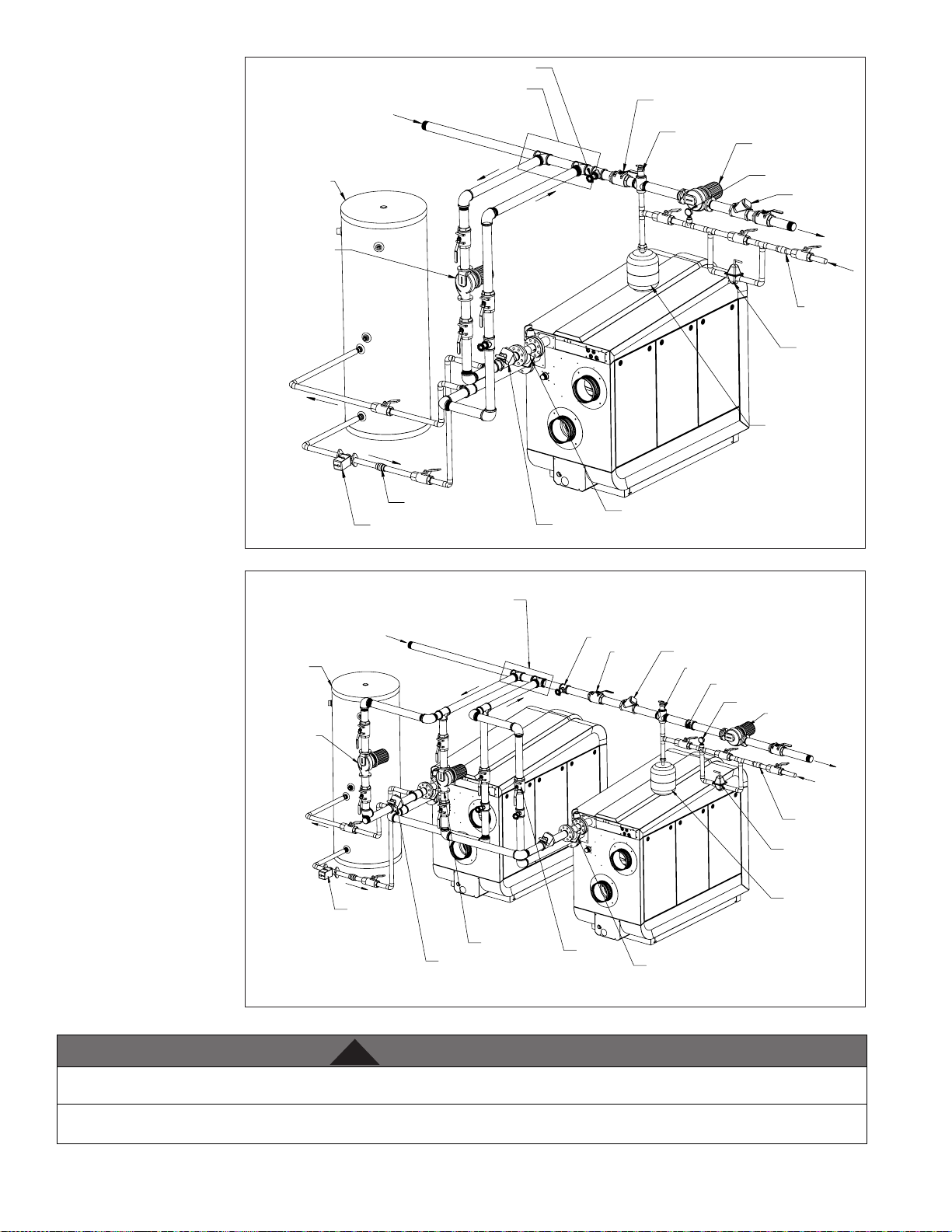
22
WARNING
!
O. Applications*
*NOTE: Systems shown are
primary/secondary piping
systems. These recommended
systems have a primary (boiler)
loop, and secondary circuits
for heating. The primary loop
and secondary circuits have
separate circulators. The use
of other near boiler piping
congurations could result in
improper ow rates, leading
to inadvertent boiler high limit
shutdowns and poor system
performance.
NOTE: In piping applications
utilizing a single zone, it
is recommended that the
installer use ow / check valves
with weighted seats at or
near the appliance to prevent
gravity circulation.
FIGURE NOTES:
1. This drawing is meant to
demonstrate system piping
concept only.
2. A mixing valve is
recommended if the DHW
temperature is set above the
factory setting of 119oF.
3. Install a minimum of 12
diameters of straight pipe
upstream of all circulators.
4. Install a minimum of 6
diameters of straight pipe up
and downstream of all closely
spaced tees.
5. Piping shown is Primary/
Secondary.
6. The minimum pipe size for
connecting an HTP indirect
red water heater is 1”.
7. DO NOT down size the boiler
heating loop connections.
8. System ow (Secondary
Loop) must be greater than the
boiler’s Primary Loop ow.
9. Installations must comply
with all local codes.
10. In Massachusetts, a vacuum
relief valve must be installed
on the cold water line per 248
CMR.
11. See Multiple Boiler Manifold
Piping chart, this manual, when
sizing and installing a multiple
boiler system.
BOILER CIRCULATOR
BOILER CIRCULATOR
INDIRECT
INDIRECT
TANK
TANK
PURGE VALVE(TYP)
MAY SUBSTITUTE FOR
LOW LOSS HEADER
4 PIPE DIA. SPACING
FROM SYSTEM
CHECK VALVE
DHW CIRCULATOR
MAXIMUM
CHECK
VALVE
Y-STRAINER
(RECOMMENDED)
Figure 12 - Single Boiler Space Heating with Indirect Priority
MAY SUBSTITUTE FOR
LOW LOSS HEADER
FROM SYSTEM
DHW CIRCULATOR
4 PIPE DIA. SPACING MAX
BOILER CIRCULATOR
CHECK VALVE
PURGE VALVE
BALL
VALVE
BALL VALVE
TYPICAL
Figure 13 - Cascaded Boilers with Indirect Priority on One
BALL VALVE
TYPICAL
AIR SEPARATOR
CHECK VALVE
AIR SEPARATOR
Y-STRAINER
RECOMMENDED
SYSTEM
CIRCULATOR
SYSTEM SENSOR
PRESSURE GAUGE
PRESSURE GAUGE
CHECK VALVE
TO SYSTEM
MAKE-UP
WATER
BACK FLOW
PREVENTER
PRESSURE
REDUCING
VALVE
EXPANSION
TANK
LP-666-C
12/20/18
SYSTEM CIRCULATOR
TO SYSTEM
MAKE-UP
WATER
BACKFLOW
PREVENTOR
PRESSURE
REDUCING VALVE
EXPANSION
TANK
LP-666-D
12/20/18
An ASSE 1017 thermostatic mixing valve is recommended on all indirect water heaters if the hot water temperature leaving the heater is
above 119oF. Failure to do so could result in substantial property damage, serious injury, or death.
The piping will not support the weight of the circulators. Refer to the circulator manufacturer’s instructions to properly support the circulator.
Failure to comply with these instructions could result in property damage, severe personal injury, or death.
lp-666 Rev. 003 Rel. 004 Date 9.3.20
Page 23
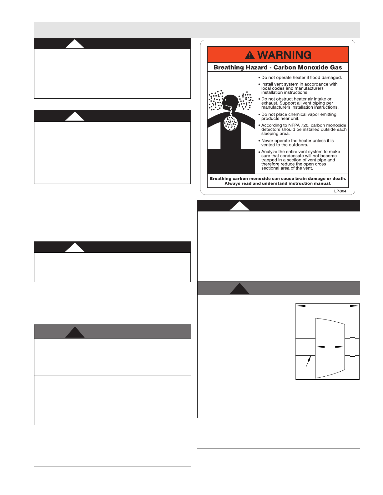
Part 5 - Venting
DANGER
!
DANGER
!
DANGER
!
WARNING
!
DANGER
!
WARNING
!
Exhaust
LP-179-JJ
11/30/17
Length
Greater than
Six (6) Inches
Enclosed
Space
Within First Three (3) Linear Feet of
Appliance Exhaust Vent Adapter
The boiler must be vented as detailed in this section. Ensure
exhaust vent and intake piping complies with these instructions
regarding vent system. Inspect nished exhaust vent and intake
piping thoroughly to ensure all joints are well secured, airtight,
and comply with all applicable code requirements, as well as the
instructions provided in this manual. Failure to properly install the
vent system will result in severe personal injury or death.
A. General
This boiler is certied as a “Category IV” appliance and requires
a special venting system. The vent system will operate with a
positive pressure in the pipe. Exhaust gases must be piped directly
outdoors using the vent materials and rules outlined in these
instructions. Do not connect vent connectors serving appliances
vented by natural draft into any portion of mechanical draft
systems operating under positive pressure. Follow the venting
instructions carefully. Failure to do so will result in substantial
property damage, severe personal injury, or death.
1. Installation should be made in accordance with the regulations of
the Authority Having Jurisdiction, local code authorities, and utility
companies which pertain to this type of water heating equipment.
2. Install the venting system in accordance with these instructions
and with the National Fuel Gas Code, ANSI Z223.1/NFPA 54, CAN/
CGA B149, and / or applicable provisions of local building codes.
3. This boiler must be vented with materials, components, and
systems listed and approved for Category IV appliances.
Exhaust and intake are to be piped separately. This boiler cannot
share a common exhaust or intake with multiple appliances.
Failure to follow these instructions will result in substantial
property damage, severe personal injury, or death.
NOTE: To avoid contamination often contained in indoor air, it is
best to pipe all intake combustion air directly to the outdoors.
NOTE: Care must be taken to prevent condensate freezing in the
exhaust vent pipe system. See local, state, provincial, and national
codes for best practices to prevent condensate freezing in the
exhaust vent pipe system.
Improper seating of vent pipe gaskets can cause eventual gasket
failure and exhaust gas leakage. Ensure the exhaust vent pipe is
properly beveled and seated before insertion into the ue adapter.
Failure to do so could result in property damage, severe personal
injury, or death.
Exhaust vent adaptors are not designed as load-bearing devices,
and must not be used to support exhaust vent piping. All vent
pipes must be properly connected, supported, and the exhaust
vent must be pitched a minimum of 1/4” per foot back to the boiler
to allow drainage of condensate. Failure to properly support vent
piping and follow the information in this statement could result in
product damage, severe personal injury, or death.
Vents must be properly supported. Boiler exhaust and intake
connections are not designed to carry heavy weight. Vent support
brackets must be within 1’ of the boiler and the balance at 4’
intervals. Boiler must be readily accessible for visual inspection
for rst 3’ from the boiler. Failure to properly support vents could
result in property damage, severe personal injury, or death.
23
Due to the extreme ammability of most glues, cements, solvents,
and primers used to join plastic exhaust vent and intake pipes,
explosive solvent vapors must be cleared from all vent piping before
start-up. Avoid using excess cement or primer, as this may pool in the
vent pipes. Vent assemblies should be allowed to cure for a period of
at least 8 hours before powering a connected appliance. Failure to
follow these instructions will result in substantial property damage,
severe personal injury, or death. It is the installers’ responsibility to
understand the hazards associated with explosive solvents and take
the necessary precautions to avoid these risks.
• DO NOT insulate the rst three (3) linear feet of the exhaust vent
run.
• CPVC, Polypropylene, or Stainless
Steel pipe material MUST be used if
the rst three (3) linear feet of the
exhaust vent run passes through an
enclosed space greater than 6” in
length, such as a wall. NOTE: Only
Stainless Steel pipe material may be
insulated.
• If CPVC is used to meet these
requirements, the balance may be
installed with approved PVC pipe.
• If Polypropylene or Stainless Steel
is used to meet these requirements, the balance of the vent run
must be installed with the same material.
• Failure to comply with this warning could result in property
damage, severe personal injury, or death.
It is required to insert exhaust and intake screens into the vent
terminations to prevent blockage caused by debris or birds. Failure
to keep terminations clear could result in property damage, severe
personal injury, or death.
lp-666 Rev. 003 Rel. 004 Date 9.3.20
Page 24
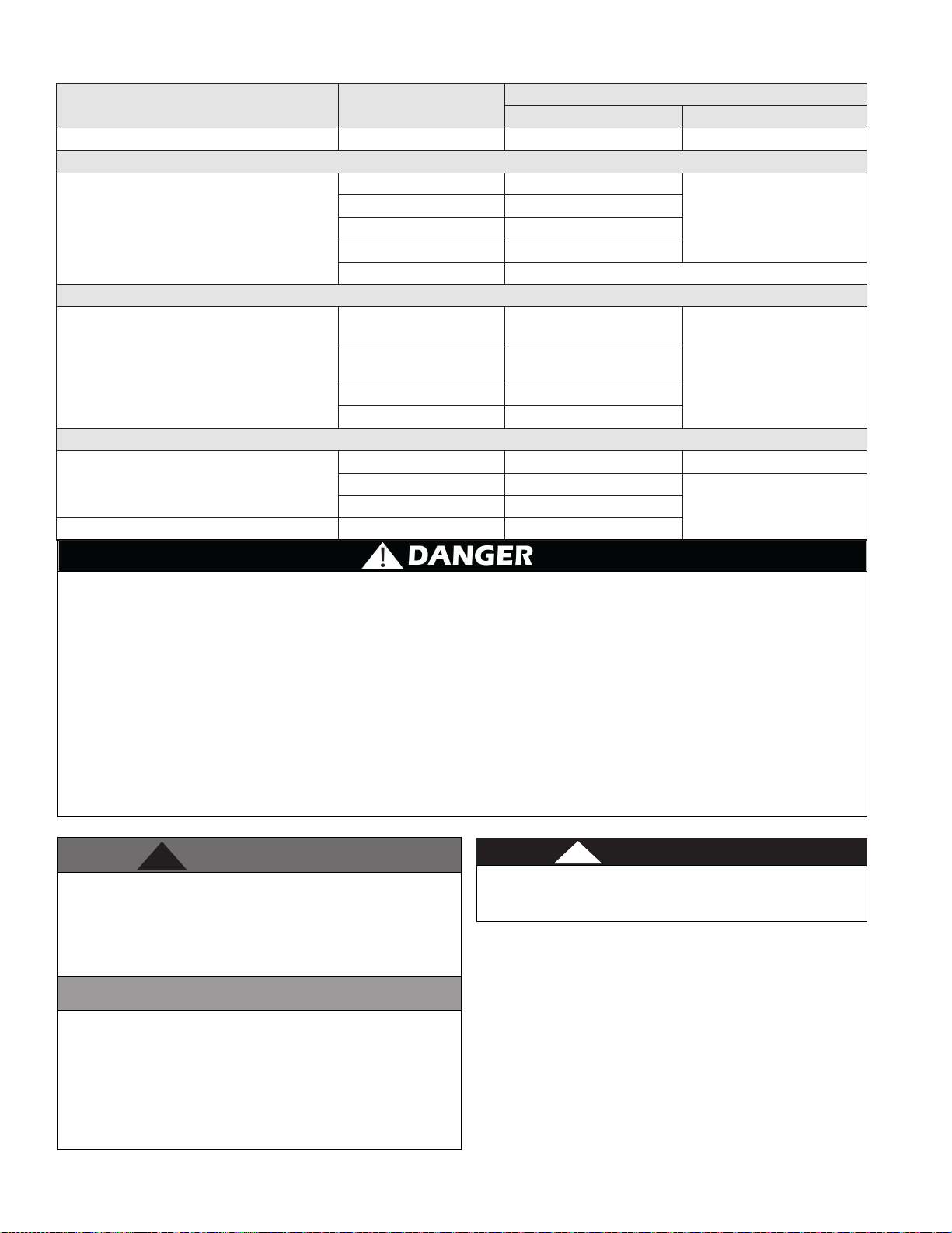
24
CAUTION
WARNING
!
DANGER
!
B. Approved Materials for Exhaust Vent and Intake Pipe
Item Material
Pipe and Fittings Approved for Intake ONLY ABS* ANSI/ASTM D2661 ANSI/ASTM D2661
PVC Schedule 40/80 UL-1738 or ANSI/ASTM D1785
Pipe Approved for
Intake OR Exhaust Vent
PVC-DWV Schedule 40/80 UL-1738 or ANSI/ASTM D2665
CPVC Schedule 40/80 UL-1738 or ANSI/ASTM F441
Polypropylene UL-1738 or ULC-S636
Stainless Steel AL29-4C Certied for Category IV and Direct Vent Appliance Venting
Standards for Installation In:
United States Canada
UL-1738 or ULC-S636
PVC Schedule 40
Pipe Fittings
Pipe Cement
Pipe Primer PVC / CPVC ASTM F656
• The exhaust and intake components installed with this appliance must be used for near appliance piping BEFORE transitioning to the
approved materials listed above. DO NOT REMOVE these installed components. Doing so WILL VOID appliance warranty.
• PVC / CPVC pipe and ttings of the same diameter are considered interchangeable.
• The use of cellular core PVC (ASTM F891), cellular core CPVC, or Radel® (polyphenolsulfone) in exhaust venting systems is prohibited.
• Covering non-metallic vent pipe and ttings with thermal insulation is prohibited.
• DO NOT connect PVC/CPVC to Polypropylene without an approved vent connector.
• Any transition to Polypropylene MUST be done in the vertical within ve (5) feet of the appliance.
• When installing AL29-4C vent piping, install a PVC-to-stainless adapter at the appliance vent connection, and at the termination
when using a PVC termination kit. DO NOT mix AL29-4C piping from dierent manufacturers unless using adapters specically
designed for the purpose by the manufacturer.
• A double wall vent or insulated material may be used when using stainless steel vent material in a freezing climate.
• *ABS may be used for air intake applications ONLY.
• Contact the venting material manufacturer if there is any question about the applicability of the proposed venting material.
Failure to follow these directions will result in substantial property damage, severe personal injury, or death.
Table 8 - Approved Materials for Exhaust Vent and Intake Pipe
PVC Schedule 80
CPVC Schedule 40 UL-1738 or ANSI/ASTM F438
CPVC Schedule 80 UL-1738 or ANSI/ASTM F439
ABS* ANSI/ASTM D2235 ANSI/ASTM D2235
PVC ANSI/ASTM D2564
CPVC ANSI/ASTM F493
UL-1738, ANSI/ASTM D2466
or D2665
UL-1738, ANSI/ASTM D2467
or D2665
UL-1738 or ULC-S636
IPEX System 636 Cements and
Primers
DO NOT mix components from dierent venting systems without
proper adapters. The vent system could fail, causing leakage of
ue products into the living space. Use only the approved pipe and
tting materials, and primer and cement specically designed for
the material used, as listed in the above table. Failure to do so could
result in property damage, serious injury, or death.
High heat sources (generating heat 100oF / 37oC or greater, such
as boiler ue pipes, space heaters, etc.) may damage plastic
components of the boiler as well as plastic vent pipe materials. Such
damages ARE NOT covered by warranty. It is recommended to keep
a minimum clearance of 8” from high heat sources. Observe heat
source manufacturer instructions, as well as local, state, provincial,
and national codes, laws, regulations, and ordinances when installing
this boiler and related components near high heat sources.
lp-666 Rev. 003 Rel. 004 Date 9.3.20
You must not use “B” vent in an exhaust application. “B” vent is for
intake applications ONLY. Using “B” vent in an exhaust application
will result in serious injury or death.
C. Additional Requirements for Installation in Canada
1. Installations must be made with a vent pipe system certied to
ULC-S636. Additionally, you may use AL29-4C stainless steel venting
to comply with Canadian requirements.
2. The rst three (3) feet of vent pipe from the boiler ue outlet must
be readily accessible for visual inspection.
3. The components of the certied vent system must not be
interchanged with other vent systems or unlisted pipe / ttings.
Page 25
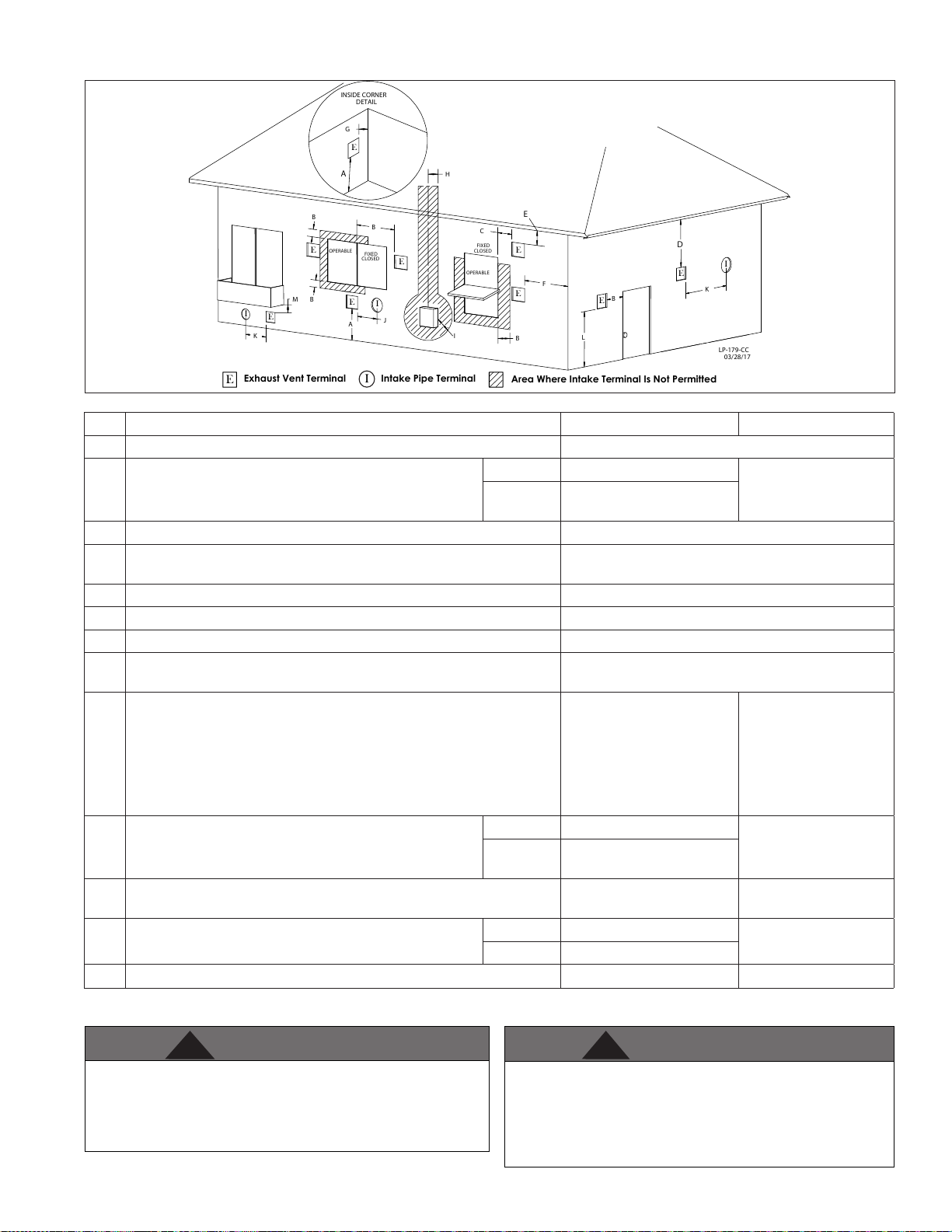
D. Exhaust Vent and Intake Pipe Location
B
H
B
B M
G
E
LP-179-CC
A
FIXED
CLOSED
OPERABLE
I
E
E
E
CLOSED
OPERABLE
FIXED
03/28/17
E
E
D
I
E
E
I
DETAIL
I
INSIDE CORNER
A
B
B
J
L
K
F
C
K
E
E
E
Exhaust Vent Terminal
I
Intake Pipe Terminal
Area Where Intake Terminal Is Not Permitted
WARNING
!
WARNING
!
Figure 14 - Exit Terminals for Direct Vent Systems - ANSI Z223.1 / NFPA 54 for US and CAN/CSA B149.1 for Canada
DESCRIPTION US CANADA
A Clearance above grade, veranda, porch, deck, or balcony 1 foot (30 cm)
Direct Vent 1 foot
B Clearance to window or door that may be opened
Power Vent
4 ft below or to side of
opening; 1 ft above opening
C Clearance to permanently closed window *
Vertical clearance to ventilated sot located above the terminal within
D
a horizontal distance 2 feet (61 cm) from the center line of the terminal
*
E Clearance to unventilated sot *
F Clearance to outside corner *
G Clearance to inside corner *
Clearance to each side of center line extended above meter / regulator
H
assembly
*
I Clearance to service regulator vent outlet *
Clearance to nonmechanical air supply inlet to building or
J
the combustion air inlet to any other appliance
K Clearance to mechanical air supply inlet
Clearance above paved sidewalk or paved driveway located
L
M Clearance under veranda, porch deck, or balcony * 1 foot (30 cm)
Table 9 - Vent Termination Clearances - *NOTE: For clearances not specied in ANSI Z223.1 / NFPA 54 for US and CAN/CSA B149.1 for Canada, please
use clearances in accordance with local installation codes and the requirements of the gas supplier.
on public property
Direct Vent 1 foot
Power Vent
4 ft below or to side of
opening; 1 ft above opening
3 feet above if within 10 feet
horizontally
Direct Vent *
Power Vent 7 feet (2.13 m)
3 feet (91 cm)
Above a regulator
within 3 feet (91 cm)
horizontally of the
vertical center line of
the regulator vent outlet
to a maximum vertical
distance of 15 ft (4.5 m)
3 feet (91 cm)
6 feet (1.83 m)
7 feet (2.13 m)
25
The building owner is responsible for keeping the exhaust and intake
terminations free of snow, ice, or other potential blockages, as well
as scheduling routing maintenance. Failure to keep the vent piping
terminations clear and properly maintain the heater could result in
property damage, severe personal injury, or death.
For each oor containing bedroom(s), a carbon monoxide
detector and alarm shall be placed in the living area outside the
bedrooms, as well as in the room that houses the heater. Detectors
and alarms shall comply with NFPA 720 (latest edition). Failure to
comply with these requirements could result in product damage,
severe personal injury, or death.
lp-666 Rev. 003 Rel. 004 Date 9.3.20
Page 26
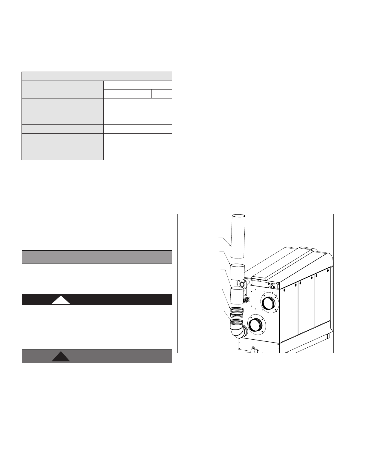
26
CAUTION
WARNING
!
DANGER
!
E. Exhaust Vent and Intake Pipe Sizing
1. The exhaust vent and intake pipe size is 4”, 6”, or 8”, depending on
model.
2. The maximum total equivalent length of exhaust vent and intake
pipe should not exceed 125 feet for 400 to 1000 models, and
150 feet for 1500 and 2000 models.
a. The equivalent length of elbows, tees, and other ttings are
listed in the Friction Loss Table.
Friction Loss Equivalent in Piping and Fittings
Fittings or Piping
90 Degree Elbow 5’
45 Degree Elbow 3’
Coupling 0’
Air Inlet Tee 0’
One Foot of Straight Pipe 1’
V Series Vent Kit 1’
AL29 4c Vent Terminal 1’
Table 10 - NOTE: Consult Polypropylene venting instructions for friction
loss and pressure drop equivalents.
b. For example: If the exhaust vent is 6” in diameter, has two 90o
elbows, and 10 feet of PVC pipe we will calculate:
Exhaust Vent Equivalent Length = (2x5) + 10 = 20 feet.
Further, if the 6” intake pipe has two 90o elbows, one 45o elbow,
and 10 feet of PVC pipe, the following calculation applies:
Intake Pipe Equivalent Length = (2x5) + 3 + 10 = 23 feet.
The total equivalent length is 43 feet, well below the maximum
of 125 feet.
c. Eort should be made to keep a minimum dierence in
equivalent length between the exhaust vent and intake pipe.
3. The minimum total equivalent length is 10 feet for 400 to 1000
models, and 15 feet for 1500 and 2000 models.
Do not exceed the maximum lengths for vent pipes. Excessive
length could result in boiler shutdown and property damage.
Failure to provide the minimum total vent length could result in
property damage and improper product operation.
Equivalent Feet
4” 6” 8”
4. When using PVC or CPVC pipe, all joints must be properly cleaned,
primed, and cemented. Use only cement and primer approved for use
with the pipe material. Cement must conform to ASTM D2564 for PVC
and ASTM F493 for CPVC pipe.
NOTE: The use of colored primer is recommended.
NOTE: DO NOT CEMENT POLYPROPYLENE PIPE. Follow
manufacturer’s instructions for proper installation.
NOTE: Clean and dry the boiler adapters.
DO NOT use primer or cement on the boiler adapters.
a. Clean all pipe ends and ttings using a clean dry rag. (Moisture will
retard curing and dirt or grease will prevent adhesion.)
b. Dry t piping to ensure proper t up before assembling any joint.
The pipe should go a third to two-thirds into the tting to ensure
proper sealing after cement is applied.
c. Priming and Cementing:
i. Handle ttings and pipes carefully to prevent contamination of
surfaces.
ii. Apply a liberal even coat of primer to the tting socket and to the
pipe end to approximately 1/2” beyond the socket depth.
iii. Apply a second primer coat to the tting socket.
iv. While primer is still wet, apply an even coat of approved cement
to the pipe equal to the depth of the tting socket along with an
even coat of approved cement to the tting socket.
v. Apply a second coat of cement to the pipe.
vi. While the cement is still wet, insert the pipe into the tting, if
possible twist the pipe a 1/4 turn as you insert it. NOTE: If voids
are present, sucient cement was not applied and joint could be
defective.
vii. Wipe excess cement from the joint removing ring or beads as it
will needlessly soften the pipe.
8" PVC PIPE
(FIELD SUPPLIED)
8" PVC COUPLING
(FIELD SUPPLIED)
8" CPVC PIPE
STARTER PIECE
MINIMUM 12" LONG
(FIELD SUPPLIED)
8" PVC TO STAINLESS STEEL (FNS)
ADAPTER
(AVAILABLE FROM FACTORY)
7550P-064
Total maximum equivalent length of exhaust vent and intake
pipe must not exceed the lengths dened in this manual. Failure
to keep the total equivalent length below the maximum lengths
determined in this manual will result in faulty boiler operation,
substantial property damage, serious personal injury, or death.
F. Exhaust Vent and Intake Pipe Installation
All joints of positive pressure vent systems must be sealed
completely to prevent leakage of ue products into the living
space. Failure to do so could result in property damage, serious
injury, or death.
1. Use only solid PVC, CPVC, or stainless steel pipe or a Polypropylene
vent system approved for use with Category IV appliances.
ABS pipe material may be used on air intake piping only.
2. Work from the boiler to exhaust vent or intake air termination.
Do not exceed the lengths given in this manual for the vent or air
piping.
3. Cut pipe to the required lengths and deburr the inside and outside
of the pipe ends. Chamfer the outside of each pipe end to ensure
even cement distribution when joining.
lp-666 Rev. 003 Rel. 004 Date 9.3.20
STAINLESS STEEL (FNS) ELBOW
(AVAILABLE FROM FACTORY)
7550P-067
LP-666-AA
04/01/20
Figure 15 - 1500 and 2000 Models - Near Boiler PVC/CPVC Venting (Flue
Connections from the Factory are sized for Stainless Steel Venting)
5. Ensure the vent is located where it will not be exposed to prevailing
winds.
6. In all roof venting applications, exhaust discharge must point away
from the pitch of the roof.
7. If the exhaust vent is to be terminated in a walled o area (such
as a roof with a parapet wall), ensure the exhaust vent terminates a
minimum of 10’ from nearest wall and extends level with or above
the top of the wall. This will ensure ue gas does not get trapped and
possibly recirculated into the intake air pipe, which could contaminate
the combustion air.
8. To prevent water leakage, install adequate roof ashing where the
pipe enters the roof.
9. Do not locate vent over public walkways, driveways, or parking lots.
Page 27
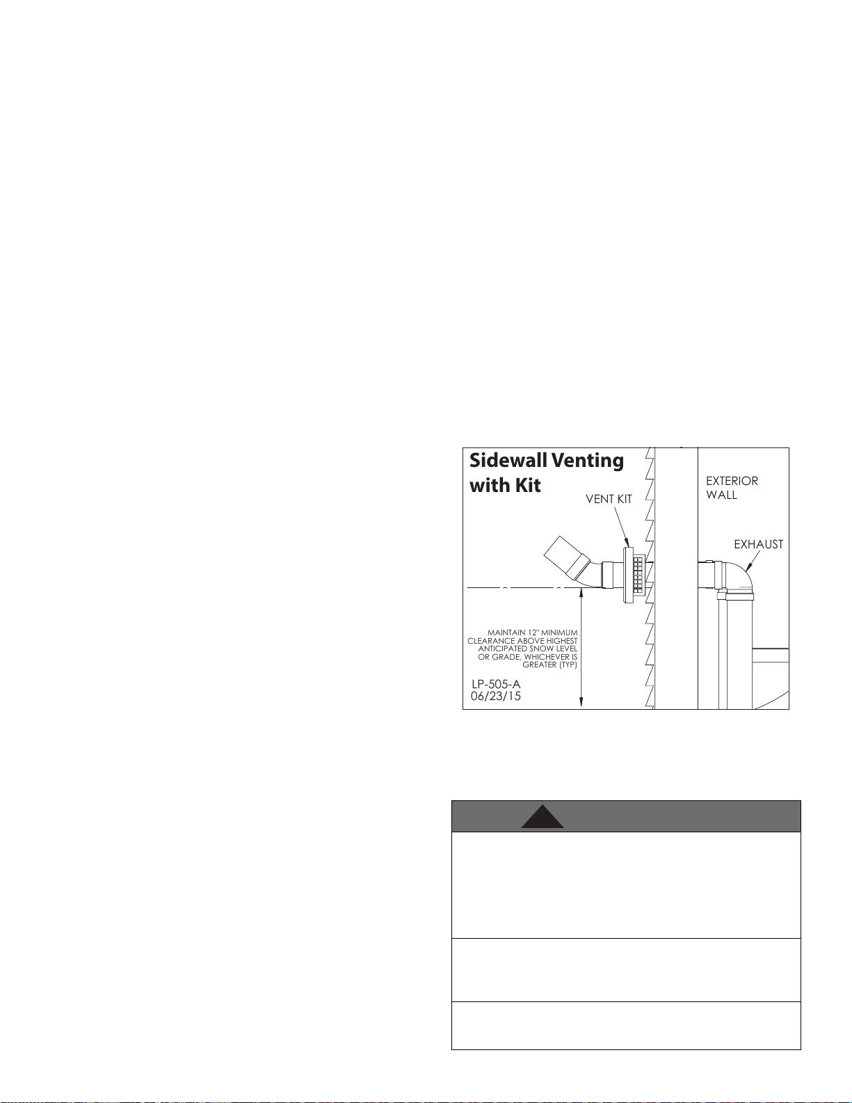
Condensate could drip and freeze, resulting in a slip hazard or damage
GREATER (TYP)
MAINTAIN 12" MINIMUM
CLEARANCE ABOVE HIGHEST
OR GRADE, WHICHEVER IS
VENT KIT
EXHAUST
ANTICIPATED SNOW LEVEL
EXTERIOR
WALL
06/23/15
LP-505-A
Sidewall Venting
with Kit
WARNING
!
to vehicles and machinery.
10. Due to potential moisture build-up, sidewall venting may not be
the preferred venting option. To save time and cost, carefully consider
venting installation and location.
11. Horizontal lengths of exhaust vent must slope back towards the
boiler not less than ¼” per foot to allow condensate to drain from the
vent pipe.
12. The exhaust vent must terminate where vapors cannot make
accidental contact with people or pets, or damage shrubs or plants.
13. In vacant chimney applications, install and seal a rain cap over
existing chimney openings.
14. All piping must be fully supported. Use pipe hangers at a minimum
of 4 foot intervals to prevent sagging of the pipe where condensate
may form.
15. Do not use the boiler to support any piping.
16. Ensure the outdoor exhaust vent and intake pipe terminations are
screened to prevent blockage caused by debris or birds.
17. Maximum Snow Level Determination: These installation
instructions reference snow levels in establishing a minimum height
for the installation of exhaust vent or air intake terminations. Snow
levels shall be determined as follows:
a. The installation location may, by ordinance, designate how snow
levels are calculated in that location; or
b. In the absence of specic ordinances, snow levels shall be calculated
from the average monthly maximum depth of snow accumulation as
indicated by the National Weather Service’s 10 year statistics for the
installation location/geographical area.
In addition:
• Total length of vent piping shall not exceed the limits specied
in this manual.
• The vent piping for this direct vented appliance is approved for
zero clearance to combustible construction.
• The ue products coming from the exhaust vent will create a
large plume when the heater is in operation. Avoid venting in
areas that will aect neighboring buildings or be considered
objectionable.
• DO NOT locate exhaust vent or intake pipe in a parking area
where machinery may damage the pipe.
• DO NOT vent near sot vents, crawl space vents, or other areas
where condensate or vapor could create a nuisance or hazard or
cause property damage.
• DO NOT vent where condensate vapor could cause damage or
could be detrimental to the operation of regulators, relief valve,
or other equipment.
In the Commonwealth of Massachusetts and as Required by State
and Local Codes:
• The vented gas fueled appliance shall not be installed so its
combustion, ventilation, or dilution air is obtained from a
bedroom or bathroom.
• Signage: Whenever any through-the-wall (horizontal or sidewall)
vent is installed less than seven feet above the nished grade,
a metal or plastic identication plate shall be permanently
mounted to the exterior of the building at a minimum height
of eight feet above grade directly in line with the exhaust vent
terminal. The sign shall read, in print no less than 0.5 inches
in size, “GAS VENT DIRECTLY BELOW. KEEP CLEAR OF ALL
OBSTRUCTIONS”.
• Marking of Exhaust Vent and Intake Pipe: Piping used for
ventilation, make-up, or combustion air intake shall be labeled
as follows:
a. Throughout the entire developed length:
i. Labels must be placed every ten feet for exposed/visible
piping; or
ii. Labels must be placed every three feet for concealed piping.
b. At all changes of direction;
27
c. On each side of a penetration through a partition, wall or
ceiling; and
d. The labels shall be black lettering that:
i. Indicates that the piping is used for ventilation, make-up,
or combustion air intake, and
ii. The letters shall be sized equal to a minimum of the pipe
diameter. However, for piping with a diameter exceeding
two inches, said lettering does not need to be larger than
two inches.
G. Applications
1. Direct Vent Installation of Exhaust and Intake
If installing a direct vent option, combustion air must be drawn
from the outdoors directly into the boiler intake, and exhaust
must terminate outside. There are three basic direct vent options
detailed in this manual: 1. Side Wall Venting, 2. Roof Venting, and 3.
Unbalanced Venting.
Be sure to locate the boiler such that the exhaust vent and intake
pipe can be routed through the building and properly terminated.
Dierent vent terminals can be used to simplify and eliminate
multiple penetrations in the building structure (see Optional
Equipment in Venting Section). The exhaust vent and intake pipe
lengths, routing and termination methods must all comply with the
methods and limits given in the Venting section of this manual.
When installing a combustion air intake from outdoors, care must be
taken to utilize uncontaminated combustion air. NOTE: To prevent
combustion air contamination, see Table 1.
Figure 16 - Sidewall Venting with Tee and Coupling and Optional Kit
NOTE: These drawings are meant to demonstrate system venting
only. The installer is responsible for all equipment and detailing
required by local codes.
Ensure the terminations are screened to prevent blockage caused
by debris or birds.
All vent pipes must be glued, properly supported, and the exhaust
pitched a minimum of 1/4” per foot back to the boiler to allow
drainage of condensate. When placing support brackets on vent
piping, the rst bracket must be within 1 foot of the boiler and
the balance of 4 foot intervals on the vent pipe. Venting must be
readily accessible for visual inspection from the rst three feet
from the boiler.
Take extra precaution to adequately support the weight of vent
pipes terminating through the roof. Failure to properly support
roof terminated vent piping could result in property damage,
serious personal injury, or death due to ue gas leakage.
An unbalanced vent system can be installed ONLY when the
exhaust is in the vertical position. Failure to do so could result in
serious personal injury or death.
lp-666 Rev. 003 Rel. 004 Date 9.3.20
Page 28

28
WARNING
!
Two Pipe Sidewall Venting
Two Pipe Roof Venting with
Intake (Elbow) and
Exhaust (Coupling)
MAINTAIN MIN 12" CLEARANCE
ABOVE HIGHEST ANTICIPATED
SNOW LEVEL OR GRADE
WHICHEVER IS HIGHER
24"
EXHAUST
AIR INTAKE
12" OVER MAXIMUM SNOW
LEVEL OR 24" WHICHEVER IS
GREATER
LP-666-G
10/18/18
Two Pipe Sidewall Venting
with Intake (Elbow) and
Coupling (Exhaust)
400 - 1000 Models ONLY
12" MIN.
GREATER (TYP)
LP-505-A
06/23/15
EXHAUST
MAINTAIN 12" MINIMUM
CLEARANCE ABOVE HIGHEST
ANTICIPATED SNOW LEVEL
OR GRADE, WHICHEVER IS
Insert Intake/Exhaust
Screen into Coupling
with Couplings (Intake and Exhaust)
1500 - 2000 Models ONLY!
EXHAUST
INSERT EXHAUST
SCREEN INTO
COUPLING
12" MIN.
1" MIN.
Insert Intake/Exhaust Screen
into Open End of Elbow
1" MIN.
EXTERIOR WALL
INTAKE
EXTERIOR WALL
Figure 17 - Roof Venting with Stainless Steel and Tee and Coupling
Figure 18 - Unbalanced Venting - Roof Exhaust and Sidewall Intake
MAINTAIN 12" MINIMUM
CLEARANCE ABOVE HIGHEST
ANTICIPATED SNOW LEVEL
OR GRADE, WHICHEVER IS
GREATER (TYP)
LP-505-A
10/30/18
INSERT SCREEN INTO COUPLING
Figure 19 - Sidewall Venting with Elbow and Coupling (400 - 1000
Models) and Couplings Only (1500 - 2000 Models ONLY)
INTAKE
NOTE: These drawings are meant to demonstrate system venting
only. The installer is responsible for all equipment and detailing
required by local codes.
Ensure the terminations are screened to prevent blockage caused
by debris or birds.
All vent pipes must be glued, properly supported, and the exhaust
pitched a minimum of 1/4” per foot back to the boiler to allow
drainage of condensate. When placing support brackets on vent
piping, the rst bracket must be within 1 foot of the boiler and
the balance of 4 foot intervals on the vent pipe. Venting must be
readily accessible for visual inspection from the rst three feet
from the boiler.
Take extra precaution to adequately support the weight of vent
pipes terminating through the roof. Failure to properly support
roof terminated vent piping could result in property damage,
serious personal injury, or death due to ue gas leakage.
An unbalanced vent system can be installed ONLY when the
exhaust is in the vertical position. Failure to do so could result in
serious personal injury or death.
lp-666 Rev. 003 Rel. 004 Date 9.3.20
Page 29

29
CAUTION
!
2. Power Venting, Room and Indoor Combustion Ventilation
Requirements
When using an indoor combustion air installation, the mechanical
room MUST be provided with properly sized openings, and/or be
of sucient volume to assure adequate combustion air and proper
ventilation for all gas red appliances in the mechanical room
to assure adequate combustion air and proper ventilation. The
requirements shown here are for the boiler only. Additional gas red
appliances in the mechanical room will require an increase in the net
free area and/or volume to supply adequate combustion air for all
appliances. This must be done in accordance with the National Fuel
Gas Code, NFPA 54 / ANSI Z223.1.
This boiler can be vented using mechanical room air only for
combustion. No combustion air openings are needed when the
boiler is installed in a space with a volume NO LESS than 50 cubic
feet per 1,000 BTU/hr of all installed gas red appliances and the
building MUST NOT BE of “Tight Construction”.
TIGHT CONSTRUCTION: A building with less than .4 ACH (air
changes per hour). For buildings of “Tight Construction”, provide air
openings into the building from the outside.
Indoor and outdoor combustion air may be combined by applying
a ratio of available volume to required volume times the required
outdoor air opening(s) size(s). This must be done in accordance with
the National Fuel Gas Code, NFPA 54 / ANSI Z223.1.
1. If air is taken directly from outside the building with no duct,
provide two permanent openings to the mechanical room each
with a net free area of one square inch per 4000 BTU/hr input. See
Figure 20.
2. If combustion and ventilation air is taken from the outdoors using
a duct to deliver the air to the mechanical room, each of the two
openings should be sized based on a minimum free area of one
square inch per 2000 BTU/hr input. See Figure 21.
3. If air is taken from another interior space combined with the
mechanical room:
a. Two spaces on same story: Each of the two openings specied
should have a net free area of one square inch for each 1000 BTU/
hr input, but not less than 100 square inches.
b. Two spaces on dierent stories: One or more openings should
have a net free area of two square inches per 1000 BTU/hr.
See Figure 22 for reference.
4. If a single combustion air opening is provided to bring combustion
air in directly from the outdoors, the opening must be sized based
on a minimum free area of one square inch per 3000 BTU/hr. This
opening must be located within 12” of the top of the enclosure. See
Figure 23.
Combustion air requirements are based on the latest edition of
the National Fuel Gas Code, NFPA 54 / ANSI Z223.1, CGA Standard
CAN/CSA B149.1 in Canada. Check all local code requirements for
combustion air.
All dimensions based on net free area in square inches. Metal
louvers or screens reduce the free area of a combustion air opening
a minimum of approximately 25%. Check with louver manufacturers
for exact net free area of louvers.
Where two openings are provided, one must be within 12” of the
ceiling, and one must be within 12”of the oor of the mechanical
room. Each opening must have a net free area as specied in Table
11. Single openings shall commence within 12” of the ceiling. The
minimum dimension of air openings should not be less than 3”.
Combustion air supply must be completely free of any ammable
vapors that may ignite, or chemical fumes which may be corrosive to
the boiler. See Table 1 for a list of combustion air contaminants. These
chemicals, when burned, form acids which quickly attack the stainless
steel heat exchanger, headers, ue connectors, and the vent system.
The result is improper combustion and premature boiler failure. Such
failure IS NOT covered under warranty.
EXHAUST FANS: Any fan or appliance which exhausts air from the
mechanical room may deplete the combustion air supply and/or
cause a downdraft in the venting system. Spillage of ue products
from the venting system into an occupied living space can cause a very
hazardous condition that must be corrected immediately.
Minimum Recommended Combustion Air Supply to Mechanical
Room
Figure 20 Figure 21
Model
400 100 100 200 200
500 125 125 250 250
650 163 163 325 325
800 200 200 400 400
1000 250 250 500 500
1500 375 375 750 750
2000 500 500 1000 1000
Model
400 400 400 800 134
500 500 500 1000 168
650 650 650 1300 217
800 800 800 1600 267
1000 1000 1000 2000 335
1500 1500 1500 3000 500
2000 2000 2000 4000 667
Table 11 - Indoor Combustion Air Sizing
*Outside Air from 2 Openings
Directly from Outdoors
Top Opening,
2
in
Inside Air from 2 Ducts Delivered from Interior
Same Story
Top Opening,
2
in
Bottom
Opening, in
Figure 22 Figure 23
2
Space
Bottom
Opening, in
*Outside Air from 2 Ducts
1
Delivered from Outdoors
Top
2
Opening, in
Dierent
Stories
Top
2
Opening, in
2
Opening, in
*Outside
Air from 1
Opening
Outdoors,
2
Bottom
Directly
from
2 1
in
1
2
The above requirements are for the boiler only; additional gas red
appliances in the mechanical room will require an increase in the net
free area and/or volume to supply adequate combustion air for all
appliances.
No combustion air openings are needed when the boiler is installed
in a space with a volume NO LESS than 50 cubic feet per 1,000 BTU/hr
of all installed gas red appliances. Buildings MUST NOT be of *”Tight
Construction”.
1
Outside air openings shall communicate with the outdoors.
2
Combined interior space must be 50 cubic feet per 1,000 BTU/hr
input. Buildings MUST NOT be of *”Tight Construction”.
Under no circumstances should the mechanical room ever be
under negative pressure. Particular care should be taken where
exhaust fans, attic fans, clothes dryers, compressors, air handling
units, etc., may take away air from the unit. Failure to follow these
instructions could result in property damage or personal injury.
lp-666 Rev. 003 Rel. 004 Date 9.3.20
Page 30

30
Figure 20 - Combustion Air from Outdoors
Figure 21 - Combustion Air through Ductwork
Part 6 - Condensate Removal
NOTE: Check with your local gas company to determine if
combustion condensate disposal is permitted in your area. In the
state of Massachusetts, condensate must be neutralized before
entering a drain.
This boiler is a high eciency appliance, and therefore produces
condensate: a by-product of the combustion process. A condensate
collection system with an internal oat switch monitors condensate
level to prevent it from backing up into the combustion system. See
Figure 24 for condensate connection and cleanout locations.
Condensate from the boiler is slightly acidic with a pH of 3.2 - 4.5.
To avoid long term damage to the drainage system and to meet
local code requirements, HTP recommends neutralizing condensate
with a Condensate Neutralizer Kit (Part # 7350P-611). The neutralizer
kit connects to the drain system and contains limestone chips
that neutralize the pH level of the condensate. The neutralizer kit
should be checked annually and the limestone chips replenished if
necessary. When replacing the limestone chips, take care to ensure
chips are no smaller than ½” to avoid blockage in condensate piping
(refer to Figure 25 for piping of the condensate neutralizer.)
Figure 22 - Combustion Air from Indoors
Figure 23 - Combustion Air from Outdoors - Single Opening
lp-666 Rev. 003 Rel. 004 Date 9.3.20
Figure 24 - Condensate Connection and Cleanout Locations
Page 31

31
CAUTION
WARNING
!
CAUTION
!
CAUTION
CONDENSATE NEUTRALIZER
PIPE HANGER
ASSEMBLIES
FOR SUPPORT
FLOOR DRAIN
CONDENSATE
NEUTRALIZER
Figure 25 - Condensate Piping
WITHOUT PUMP
HORIZONTAL LINES
MUST BE INSTALLED WITH
A PITCH OF 1/4" PER FOOT
SWEAT PVC TEE OPEN TO
ATMOSPHERE (TO PREVENT VACUUM)
PIPE HANGER
FOR SUPPORT
NOTES:
1. Condensate line must be pitched at least ¼” per foot to properly
drain. If this cannot be done, or a very long length of condensate
hose is used, increase the condensate line and place a tee in the line
before the condensate neutralizer to properly reduce vacuum lock
in the drain line.
2. PVC or CPVC pipe should be the only material used for condensate
line. Steel, brass, copper, and other metals will be subject to corrosion
or deterioration.
3. A frozen condensate line could result in a blocked vent condition.
It is very important to protect the condensate line from freezing
temperatures or any type of blockage. In installations that may
encounter sustained freezing conditions, the use of heat tape is
recommended to avoid freezing of the condensate line. It is also
recommended to bush up the condensate line size and terminate
condensate discharge as close to the unit as possible. Longer
condensate runs are more prone to freezing. Damages due to frozen
or blocked condensate lines ARE NOT covered by warranty.
4. Support of the condensate line may be necessary to avoid
blockage of the condensate ow.
5. To allow proper drainage on longer horizontal condensate runs,
tubing size may need to increase and a second line vent may be
required.
NOTE: To clean out condensate trap, see Maintenance section.
CONDENSATE NEUTRALIZER
ASSEMBLIES
CONDENSATE
WITH PUMP
SWEAT PVC TEE OPEN TO
ATMOSPHERE
(TO PREVENT VACUUM)
PUMP
CONDENSATE
NEUTRALIZER
HORIZONTAL LINES MUST BE
INSTALLED WITH A PITCH OF
1/4" PER FOOT
Part 7 - Wiring - 400 - 1500 Models
To avoid electrical shock, turn o all power to the boiler prior to
opening an electrical box within the unit. Ensure the power remains
o while any wiring connections are being made. Failure to follow
these instructions could result in component or product failure,
serious injury, or death. Such product failure IS NOT covered by
warranty.
Jumping out control circuits or components WILL VOID product
warranty and can result in property damage, personal injury, or
death.
It is of extreme importance that this unit be properly grounded. It
is very important that the building system ground is inspected by
a qualied electrician prior to making this connection. Electrical
power must only be turned on when the boiler is completely lled
with cold water. Failure to follow these instructions could result in
component or product failure, serious injury, or death.
Electrical Shock Hazard - Turn o electrical power supply at service
entrance panel before making any electrical connections. Failure to
follow to do so could result in serious injury, or death.
LP-666-N
11/01/18
The condensate line must remain unobstructed. If allowed to
freeze in the line or obstructed in any other manner, condensate
can exit from the boiler tee, resulting in potential water damage
to property. When installing a condensate pump, select one
approved for use with condensing boilers and furnaces. The
condensate pump should have an overow switch to prevent
property damage from spillage. Condensate from the boiler will
be slightly acidic (pH from 3.2 to 4.5). Install a neutralizing lter if
required by local codes.
Is is very important that condensate piping be no smaller than
3/4”. Use a tee at the condensate connection with a branch
vertically up and open to the atmosphere to prevent a vacuum
that could obstruct the ow of condensate from the boiler. To
prevent sagging and maintain pitch, condensate piping should be
supported with pipe supports.
When installing a condensate pump, select one approved for use
with condensing boilers and furnaces. The pump should have an
overow switch to prevent property damage from condensate
spillage.
Label all wires prior to disconnecting them when servicing the
boiler. Wiring errors can cause improper and dangerous operation.
Failure to follow these instructions may result in property damage
or personal injury.
Wiring must be NEC Class 1. If original wiring supplied with the boiler
must be replaced, use only TEW 105 oC wire or equivalent. Boiler
must be electrically grounded as required by the National Electrical
Code, ANSI/NFPA 70 - Latest Edition.
A. Installation Must Comply With
1. National Electrical Code and any other national, state, provincial, or
local codes or regulations.
2. In Canada, CSA C22.1, Canadian Electrical Code Part 1, and any local
codes.
B. Field Wiring
All connections made to the boiler in the eld are done inside the
electrical junction box located on the right side of the unit when
viewed from the front. Multiple knockout locations are available to
route eld wires into and out of the electrical junction box.
The control used in the boiler is capable of directly controlling 2
pumps in standard mode and 3 pumps when congured as a cascade
master boiler. An external contactor relay or motor starter is required.
The Field Connection Board has separate, clearly marked terminal
lp-666 Rev. 003 Rel. 004 Date 9.3.20
Page 32

32
WARNING
!
strips for line voltage and low voltage wiring. Special jacks are provided
for trouble-free cascade system wiring using standard CAT3 or CAT5
patch cables.
C. Line Voltage Wiring for Standard Boiler
NOTE: A termination plug is included in the CAT 3 / CAT 5 Bus
Connection Point, labeled J6 in Figure 29. DO NOT REMOVE THIS PLUG!
Doing so will aect boiler operation and void warranty.
1. Connect the incoming power wiring to the line voltage terminal
strip in the electrical junction box at terminals L (Line), N (Neutral), and
G (Ground) (shown in Figure 27).
2. A line voltage fused disconnect switch may be required to be
externally mounted and connected according to local wiring codes.
3. Connect the boiler pump relay COIL contacts as shown in Figure 27
to the terminals marked CL (BOILER HOT) and CN (BOILER NEUT).
4. Connect an externally provided 120VAC line to the COMMON
terminal of the boiler pump relay.
5. Connect the NO relay contact to the LINE input of the boiler pump.
6. Connect the Neutral of the externally provided 120VAC to the
NEUTRAL input of the pump.
7. Connect the Earth Ground of the externally provided 120VAC to the
Earth Ground input of the pump.
8. If using DHW, connect the DHW pump relay COIL contacts as shown
in Figure 27 to the terminals marked DL (DHW HOT) and DN (DHW
NEUT).
9. Connect an externally provided 120VAC LINE to the COMMON
terminal of the DHW pump relay.
10. Connect the NO relay contact to the LINE input of the DHW pump.
11. Connect the Neutral of the externally provided 120VAC to the
NEUTRAL input of the DHW pump.
12. Connect the Earth Ground of the externally provided 120VAC to
the Earth Ground input of the DHW pump.
D. Alarm Connections
The control includes a dry contact alarm output. This is an SPDT circuit,
rated at 5 amps at 120 volts. This contact can be used to activate an
alarm light or bell or notify a building management system if the
boiler goes into a lockout condition. The circuit between the common
and ALARM NC terminals is closed during normal operation and the
circuit between the common and ALARM NO is open during normal
operation. HTP oers an Alarm System Kit (part # 7350P-602).
E. Low Voltage Connections for Standard Boiler
1. All low voltage cables should enter the electrical junction box
through the provided knock out holes as shown in Figure 27.
2. Connect all low voltage eld devices to the low voltage terminal
strip located in the electrical junction box.
F. Thermostat
1. Connect the room thermostat to the terminals marked TT- and TT+
of the Field Connection Board (shown in Figure 30). Alternately, any
dry contact closure across these terminals will cause the boiler to run.
Caution should be taken to ensure neither of the terminals becomes
connected to ground.
2. Mount the thermostat on an inside wall as centrally as possible to
the area being heated, but away from drafts or heat producing devices
such as television sets that could inuence the ability of the thermostat
to measure room temperature.
G. Outdoor Sensor
NOTE: There is no connection required if an outdoor sensor is not used
in this installation.
1. If using an outdoor sensor, connect wires for sensor to the terminals
marked OUT- and OUT+, shown in Figure 30 of the Field Connection
Board. Caution should be used to ensure neither of these terminals
becomes connected to ground.
2. Use a minimum 22 AWG wire for runs of 100 feet or less and minimum
18 AWG wire for runs of up to 150 feet.
400 - 1500 Models
Figure 26 - Knockout Locations - 400 - 1500 Models Only
3. Mount the outdoor sensor on an exterior surface of the building,
preferably on the north side in an area that will not be aected by
direct sunlight and will be exposed to varying weather conditions.
H. Indirect Sensor
NOTE: There is no connection required if an indirect water heater is
not used in this installation.
1. The boiler will operate an indirect red water heater with either
a thermostat type aquastat installed in the indirect tank, or an HTP
7250P-325 tank sensor. When a tank sensor is used, the control will
automatically detect its presence and a demand for heat from the
indirect water heater will be generated when the tank temperature
falls below the user selected set point by more than the user
selected oset. The demand will continue until the sensor measures
that the indirect water heater temperature is above the set point.
2. Connect the indirect tank sensor (7250P-325) to the terminals
marked DHW- and DHW+, shown in Figure 30 on the Field
Connection Board of the Master boiler.
Failure to use the correct sensor may result in tank temperature
being either above or below set point, and could result in decreased
performance, substantial property damage, or heightened risk of
injury or death due to scalds.
Caution should be used to ensure neither of these terminals
becomes connected to ground.
NOTE: If sensor wires are located in an area with sources of potential
electromagnetic interference (EMI), the sensor wires should be
shielded, or the wires routed in a grounded metal conduit. If using
shielded cable, the shielding should be connected to the common
ground of the boiler.
I. UL 353 Internal Low Water Cut-O (Factory Installed)
The supplied internal Low Water Cuto (LWCO) meets UL 353
requirements to function as a safety, locking out the boiler when
water level is inadequate for safe operation. See Service Mode, this
manual, for instructions on how to test and reset the Internal LWCO.
J. Wiring of Cascade System Communication Bus
1. A Cascade Bus Termination Plug has been installed on the
customer connection board of this boiler. The purpose of this plug
is to stabilize communication between multiple boilers and reduce
electrical “noise”. See Figure 29 for Cascade Bus Termination Plug
installation detail.
NOTE: It is important that the termination plug in multiple boilers
(cascaded units) be installed as depicted in Figure 29. Leave the
plug installed in the J6 port on the Master boiler. Remove the plug
on intermediate Follower boilers. Move the plug to the J7 port on
the nal Follower boiler.
lp-666 Rev. 003 Rel. 004 Date 9.3.20
Page 33

33
2. Use standard CAT3 or CAT5 computer network patch cables to
connect the communication bus between each of the boilers. These
cables are readily available at any oce supply, computer, electronic,
department or discount home supply store in varying lengths. If you
possess the skills you can also construct custom length cables.
NOTE: Shielded three-conductor cable may be used as an alternate
method to connect cascade wiring. Connect the three wires of the
shielded cable to the screw terminals labelled BUS A, BUS B, and BUS
G. Observe proper polarity across all cascaded units. See Figure 30.
NOTE: All termination plugs must be installed as described in Figure
29 to ensure proper cascade operation.
3. It is recommended to use the shortest length cable that will
reach between the boilers and create a neat installation. Do not
run unprotected cables across the oor where they may become
wet or damaged. Avoid running communication cables parallel
and close to or against high
voltage (120 volt or greater)
wiring. HTP recommends
that the maximum length of
communication bus cables not
exceed 200 feet.
4. Route the communication
cables through one of the
knockouts in the cabinet.
5. Connect the boilers in a daisy
chain conguration. It is best
to wire the boilers using the
shortest wire runs rather than
trying to wire them in the order
that they are addressed. The
communication bus jacks on
the customer connection panel
are interchangeable so you can
use either one or both in any
order to connect the cable.
If you have connected the
boilers to each other properly,
there will be no open
communication connection
ports.
K. Cascade Master System Pump and Sensor Wiring
1. Connect the system pump relay COIL contacts as shown in Figure
27 to the terminals marked SL (SYSTEM HOT) and SN (SYSTEM NEUT).
2. Connect an externally provided 120VAC line to the COMMON
terminal of the system pump relay.
3. Connect the NO relay contact to the LINE input of the system pump.
4. Connect the Neutral of the externally provided 120VAC to the
NEUTRAL input of the system pump.
5. Connect the Earth Ground of the externally provided 120VAC to the
Earth Ground input of the system pump.
6. Connect the system pipe sensor to the terminals marked SYS- and
SYS+. See Figure 30.
7. Connect the outdoor sensor (if used) to the terminals marked OUTand OUT+.
8. Connect the signal to start the system to the terminals marked TTand TT+.
NOTE: This signal can come from a room thermostat or a dry contact
closure. No power of any voltage should be fed into either of these
terminals.
L. Cascade Follower Pump and Sensor Wiring
If the boiler will control the boiler pump:
1. Connect the boiler pump relay COIL contacts as shown in Figure
28 to the terminals marked CL (BOILER HOT) and CN (BOILER NEUT).
2. Connect an externally provided 120VAC line to the COMMON
terminal of the boiler pump relay.
3. Connect the NO relay contact to the LINE input of the boiler pump.
4. Connect the Neutral of the externally provided 120VAC to the
NEUTRAL input of the pump.
5. Connect the Earth Ground of the externally provided 120VAC to
the Earth Ground input of the pump.
If the boiler will be connected directly to an indirect red water
heater:
6. If using DHW, connect the DHW pump relay COIL contacts as
shown in Figure 28 to the terminals marked DL (DHW HOT) and DN
(DHW NEUT).
7. Connect an externally provided 120VAC LINE to the COMMON
terminal of the DHW pump relay.
8. Connect the NO relay contact to the LINE input of the DHW pump.
9. Connect the Neutral of the externally provided 120VAC to the
NEUTRAL input of the DHW pump.
10. Connect the Earth Ground of the externally provided 120VAC to
the Earth Ground input of the DHW pump.
If the boiler will be connected to an alarm bell or light:
The normally closed alarm contact may be used to turn a device o
if the boiler goes into lockout mode. The alarm contacts are rated 5
amps at 120 VAC.
1. To connect an alarm device, connect the power for the device to
the common (ALARM Center) terminal. Connect the alarm device
hot wire to the NO (ALARM NO) terminal. Connect the neutral or
return of the alarm device to the neutral or return of the power for
the alarm device. See Figure 28.
2. To connect a device that should be powered o during a boiler
lockout condition, follow the same instructions as above and use
the NC (ALARM NC) terminal rather than the ALARM NO terminal.
NOTE: In a cascade system, the alarm output of the boiler addressed
as #1 will activate if any boiler has a lockout condition. The alarm
of boilers addressed #2-7 will only activate if a lockout condition
occurs on that specic boiler.
M. Variable Speed Pumping
Variable speed pump support is available on the primary loop of all
models. This feature controls pump speed via an analog 0-10VDC
signal supplied via the 0-10VA connection on the Field Connection
Board.
When this feature is in use, an installer selected Delta T is maintained
with the Supply and Return sensors, increasing eciency and
providing better system temperature control. When the dierence
between the Supply and Return temperatures is greater than
the desired setting, the pump will increase speed and ow to
compensate. Conversely, if the Delta T is less than the desired
setting, the pump will decrease speed and ow to compensate.
NOTE: This feature may be used in Primary / Secondary piping
arrangements ONLY!
Variable Speed Pumping Wiring:
1. Connect the boiler pump relay COIL contacts as shown in Figure
27 to the terminals marked CL (BOILER HOT) and CN (BOILER NEUT).
2. Connect an externally provided 120VAC line to the COMMON
terminal of the boiler pump relay.
3. Connect the NO relay contact to the LINE input of the boiler pump.
4. Connect the Neutral of the externally provided 120VAC to the
NEUTRAL input of the pump.
5. Connect the Earth Ground of the externally provided 120VAC to
the Earth Ground input of the pump.
lp-666 Rev. 003 Rel. 004 Date 9.3.20
Page 34

34
NOTE: The connections shown are suitable for a maximum
continuous pump draw of 2 amps at 120 volts. If the pump requires
2 amps or less at 120 volts, a relay is not required, and the pump may
be wired directly into the CN, CL, and CG terminals on the Customer
Connection Board.
6. Connect the 0-10V input wires on the variable speed pump to the
0-10VA output on the Field Connection Board. Connect the positive
pump input wire to 0-10VA+, and the negative wire to 0-10VA-.
NOTE: When making wiring connections, ensure proper polarity or
the system will not operate properly.
N. Optional 0-10 Volt Building Control Signal
1. A signal from a building management system may be connected
to the boiler to enable remote control. This signal should be a 0-10
volt positive-going DC signal. When this input is enabled using the
installer menu, a building control system can be used to control
the set point temperature or ring rate of the boiler. The control
interprets the 0-10 volt signal as follows; when the signal is between
0 and 1.5 volts, the boiler will be in standby mode, not ring. When
the signal rises above 1.5 volts, the boiler will ignite. As the signal
continues to rise towards its maximum of 10 volts, the boiler will
increase in either set point temperature or ring rate depending on
the setting of Function 17 in the Installer Menu. See this manual for
details on the setting of Functions 16 and 17 for this option. When
the signal drops below 1.3 volts the boiler will stop ring.
2. Connect a building management system or other auxiliary control
signal to the terminals marked 0-10V+ and 0-10V– on the Field
Connection Board (shown in Figure 30). Caution should be used to
ensure that the 0-10V+ connection does not become connected to
ground.
P. Optional Low Gas Pressure Switch
1. If an optional low gas pressure switch is used, it should be installed
on the side of the gas valve. This is normally closed and will open if the
pressure goes below 2” w.c. on the inlet side.
2. Locate the two pigtails hanging from the electrical box inside of the
boiler cabinet. Remove and discard the jumper plug from one of the
unused pigtails.
3. Connect the low gas pressure switch to the pigtail that you removed
the jumper plug from.
Q. Optional High Limit Manual Reset
NOTE: Follow the more detailed instructions included with the high
limit manual reset kit for proper installation steps.
1. Thread the control well into the tting provided on the manifold
using teon thread tape.
2. Insert the control probe into the control well.
3. Secure the high limit manual reset box to the control well.
4. Locate and disconnect the red high limit manual reset wires in the
boiler harness from each other. Connect those two red wires to the
wires on the manual reset box.
5. When installation is complete, power up the boiler and test the
reset according to the provided instructions. If the reset operates
properly, set the high limit temperature as described in the provided
instructions. When done, create a demand and observe boiler function
to verify the installation is working properly.
O. Optional High Gas Pressure Switch
1. If an optional high gas pressure switch is used, it should be
installed on the side of the gas valve. This is normally closed and will
open if the pressure goes above 15.5” w.c. on the outlet side.
2. Locate the two pigtails hanging from the electrical box inside of
the boiler cabinet. Remove and discard the jumper plug from one of
the unused pigtails.
3. Connect the high gas pressure switch to the pigtail that you
removed the jumper plug from.
lp-666 Rev. 003 Rel. 004 Date 9.3.20
Page 35

GREEN (GROUND)
35
400-1500 HIGH VOLTAGE
CUSTOMER CONNECTION BOARD
SINGLE BOILER AND CASCADE MASTER
120V LINE
120V NEUT
120V GND
** REQUIRED WHEN PUMP CURRENT > 2 AMPS
N
G
N
G
N
G
SYSTEM
PUMP
DHW
PUMP
BOILER
PUMP
PUMP
L
RELAY
**
PUMP
L
RELAY
**
PUMP
L
RELAY
**
WHITE (NEUTRAL)
BLACK (HOT)
LINE VOLTAGE
IN 120VAC
P2
SG
SN
SL
P3
DG
DN
DL
P4
CG
CN
CL
POWER
SWITCH
BLOWER
LP-666-X
09/20/19
BLK/BLU
BLACK
P1
LED1
N G
L
J5
SWITCH
J1
F1
S
2A2A2A
J7
F2
PUMP
POWER
U1
J4
FAN
15A
F4
5V DC (USB)
WIFI POWER
D
LED2
F3
GROUND J6
K1
C
ALARM
P5
NC
NO
NC
NO
NC
ALARM
NO
LED3
Figure 27 - Cascade Master and Single Boiler High Voltage Wiring - 400 - 1500 Models
GREEN (GROUND)
WHITE (NEUTRAL)
400-1500 HIGH VOLTAGE
CUSTOMER CONNECTION BOARD
CASCADE FOLLOWER
120V LINE
120V NEUT
120V GND
N
G
BOILER
PUMP
** REQUIRED WHEN PUMP CURRENT > 2 AMPS
PUMP
L
RELAY
**
BLACK (HOT)
LINE VOLTAGE
IN 120VAC
P2
SG
SN
SL
P3
DG
DN
DL
P4
CG
CN
CL
P1
L
F1
S
LED1
F2
D
LED2
F3
C
LED3
N G
2A2A2A
J7
PUMP
POWER
GROUND J6
POWER
SWITCH
BLK/BLU
J5
SWITCH
J1
U1
BLOWER
BLACK
J4
FAN
15A
F4
5V DC (USB)
WIFI POWER
K1
ALARM
P5
NC
NO
NC
NO
NC
ALARM
NO
Figure 28 - Cascade Follower High Voltage Wiring - 400 - 1500 Models
lp-666 Rev. 003 Rel. 004 Date 9.3.20
Page 36

36
Figure 29 - Cascade Termination Plug Detail
ELX 400-2.0 LOW VOLTAGE
CUSTOMER CONNECTION BOARD
SINGLE BOILER AND CASCADE MASTER
CASCADE BUS
TERMINATION PLUG
INSTALLED HERE
CASCADE BUS
ELX 400-2.0 LOW VOLTAGE
CUSTOMER CONNECTION BOARD
CASCADE FOLLOWER
CASCADE BUS
CASCADE BUS
TERMINATION PLUG
INSTALLED HERE IN
FINAL CASCADED BOILER
BIC 928
J6
X5
11
20
J7
1
10
P10
J8
P9
BUS G
BUS B
BUS A
0-10 VOLT -
OUT A +
0-10 VOLT -
OUT B +
EXT
LWCO
-
S
SYSTEM SENSOR
+
-
0-10V
+
INPUT
THERMOSTAT
T
OUTDOOR SENSOR
O
DHW SENSOR
D
BIC 928
J6
X5
11
20
Figure 30 - Cascade Master and Single Boiler Low Voltage Wiring, and Cascade Follower Low Voltage Wiring
J7
1
10
P10
J8
P9
BUS G
BUS B
BUS A
EXT
LWCO
LP-666-X2
09/18/19
lp-666 Rev. 003 Rel. 004 Date 9.3.20
Page 37

ELX-400-1500
WIRING DIAGRAM
37
120 VAC
LINE
P1-1
J1
J5
POWER
SWITCH
F4
15A
DUAL FLUE SENSOR
S3
S4
LWCO
DUAL SUPPLY SENSOR
PROBE
JUMPER JUMPER
OPTIONAL
LOW GAS
PRESSURE
HIGH GAS
PRESSURE
FLOWSWITCH
BLOCKED VENT
PRESSURE SW.
CONDENSATE
OUTDOOR
DHW TANK
0-10 VOLT
+
0-10 VOLT
TT TERMINALS
RS485 BUS
RS485 BUS
-
P10-5
P10-6
B
J6-5
J6-4
A
J6-3
G
J7-5
B
J7-4
A
J7-3
G
0-10V A OUT
0-10V B OUT
XLWCO
JUMPER
SYSTEM
LOW VOLTAGE CONNECTION BOARD
P10-3
P10-4
P10-1
P10-2
P10-7
P10-8
+
-
+
-
+
-
+
-
P9-6
P9-5
P9-3
P9-4
P9-1
P9-2
P10-10
P10-9
S1
S2
BLUE
RETURN SENSOR
P9-9
P9-8
P9-10
J7-2
BLK
WHT
GRN
HMI DISPLAY
P1-3
X11-1
X11-4
X11-2
X-2
BRN/BLUE
ORN
WHITE
PINK
RED
X7-8 X7-18
RED
X6-6
X6-7
X6-15
X6-16
X10-7
X14-2
X11-5
X10-6
X10-7
X10-4
X10-1
X9-7
X9-6
X9-4
X9-1
X9-3
X9-2
X8-1
X8-2
X5-19
X5-20
X5-17
X5-7
J5-18
J5-8
J5-11
J5-2
J5-1
J5-13
J5-3
J5-14
J5-4
J5-15
J5-5
J5-16
J5-6
MANUAL RESET
HIGH LIMIT
(OPTIONAL)
X5-15
X5-16
X6-10
X7-3
X7-13
X7-2
X7-12
X7-4
X7-14
X6-8
X6-17
X7-1
X7-11
X6-9
X6-18
X7-5
X7-15
X5-8
X5-6
X6-1
X5-14
X6-3
X6-12
X6-2
X5-14
X5-1
X5-2
X5-9
X6-4
X5-14
X6-5
X5-13
X7-7
X7-17
X5-7
X5-13
BRN
BLK
TAN
YEL
ORN
WHITE
BROWN
BROWN
BROWN
RED
RED
PINK
PINK
RED
GRN
LT. GRN
LT. BLUE
RED
RED/BLUE
GRY
BLUE
BLK/BLUE
RED/BLUE
GRN/LT BLUE
RED
BLUE
RED
BLUE
BROWN
WHITE
PPL
PPL
RED
X7-9 X7-19
M
F
PROTECTED BY
AN INTERNAL
6.3 AMP FUSE
928
CONTROL
RED
BURNER DOOR ECO
* NOTE: "J" REFERENCES FIELD CONNECTION BOARD
J7-3
P1-2
PWM
RED
+24V
WHT
HALL
NEG
LT. BLUE
WHT
NEUT.
BLOWER
MOTOR
SPARK
TRANSFORMER
BLK
J7-8
2A
F3
J7-3
J7-7
2A
F2
J7-6
2A
F1
BLK
WHT
BRN
BLUE
GAS VALVE
BLK/BLUE
ALARM
BLK/BLUE
ALARM
NO
K1
ALARM
COM
K1
ALARM
NC
HIGH VOLTAGE CONNECTION BOARD
HOT BLACK
ORANGE SPARK CAB LE
TO SPARK ELECTROD E
FLAME RECTIFICATION
P4-3
LED3
P4-2
P3-3
LED2
P3-2
P2-3
LED1
P2-2
P5-3
P5-2
P5-1
NEUTRAL
PROBE
L
L
L
CH PUMP
N
DHW PUMP
N
SYSTEM PUMP
N
Figure 31 - Internal Connection Diagram - 400 - 1500 Models
lp-666 Rev. 003 Rel. 004 Date 9.3.20
Page 38

38
WARNING
!
CAUTION
!
CAUTION
Part 8 - Wiring - 2000 Models
To avoid electrical shock, turn o all power to the boiler prior
to opening an electrical box within the unit. Ensure the power
remains o while any wiring connections are being made.
Failure to follow these instructions could result in component or
product failure, serious injury, or death. Such product failure IS
NOT covered by warranty.
Jumping out control circuits or components WILL VOID product
warranty and can result in property damage, personal injury, or
death.
It is of extreme importance that this unit be properly grounded. It
is very important that the building system ground is inspected by
a qualied electrician prior to making this connection. Electrical
power must only be turned on when the boiler is completely
lled with cold water. Failure to follow these instructions could
result in component or product failure, serious injury, or death.
Electrical Shock Hazard - Turn o electrical power supply at
service entrance panel before making any electrical connections.
Failure to follow to do so could result in serious injury, or death.
Label all wires prior to disconnecting them when servicing
the boiler. Wiring errors can cause improper and dangerous
operation. Failure to follow these instructions may result in
property damage or personal injury.
Wiring must be NEC Class 1. If original wiring supplied with the
boiler must be replaced, use only TEW 105 oC wire or equivalent.
Boiler must be electrically grounded as required by the National
Electrical Code, ANSI/NFPA 70 - Latest Edition.
A. Installation Must Comply With
1. National Electrical Code and any other national, state, provincial,
or local codes or regulations.
2. In Canada, CSA C22.1, Canadian Electrical Code Part 1, and any
local codes.
B. Field Wiring
All connections made to the boiler in the eld are done inside the
electrical junction box located in the front and left sides of the
unit. The High Voltage electrical junction box is located on the left
side of the boiler, and the Low Voltage Field Connection Board is
located to the right of the BIC928 control, on the control panel.
Multiple knockout locations are available to route eld wires into
and out of the electrical junction box.
The control used in the boiler is capable of directly controlling
2 pumps in standard mode and 3 pumps when congured as a
cascade master boiler.
An external contactor relay or motor starter is required. The High
and Low Voltage Field Connection Boards have separate, clearly
marked terminal strips for line voltage and low voltage wiring.
Special jacks are provided for trouble-free cascade system wiring
using standard CAT3 or CAT5 patch cables.
Ground goes to the G terminal. Neutral goes to N. The three Hot legs
connect to the L1-L3 terminals.
3. A line voltage fused disconnect switch may be required to be
externally mounted and connected according to local wiring codes.
CH Pump Wiring
Connect the Line of an externally provided 120VAC service to the
CENTER terminal of the three terminal barrier strip labelled P2 NO
(Normally Open).
1. Connect the boiler pump relay COIL Line input to the TOP terminal
of P2 NO (Normally Open).
2. Connect the Neutral of an externally provided 120VAC service to the
Neutral COIL terminal of the pump relay.
3. Connect the Line of an externally provided 120VAC service to the NO
CONTACT of the pump relay.
4. Connect the other NO relay CONTACT to the LINE input of the boiler
pump.
5. Connect the Neutral of an externally provided 120VAC service to the
Neutral input of the pump.
6. Connect the Earth Ground of the externally provided 120VAC to the
Earth Ground input of the pump.
DHW Pump Wiring
1. Connect the Line of an externally provided 120VAC service to the
CENTER terminal of the three terminal barrier strip labelled P4 NO
(Normally Open).
2. Connect the DHW pump relay COIL Line input to the TOP terminal of
P4 NO (Normally Open).
3. Connect the Neutral of an externally provided 120VAC service to the
Neutral COIL terminal of pump relay.
4. Connect the Line of an externally provided 120VAC service to the NO
CONTACT of the pump relay.
5. Connect the other NO relay CONTACT to the LINE input of the DHW
pump.
6. Connect the Neutral of an externally provided 120VAC service to the
Neutral input of the pump.
7. Connect the Earth Ground of the externally provided 120VAC to the
Earth Ground input of the pump.
LOW VOLTAGE - 2000 Model
SYS PUMP
PORT
DHW PUMP
PORT
CH PUMP
PORT
208VAC-3P WYE
VOLTAGE
INPUT
C. Line Voltage Wiring for Standard Boiler
NOTE: A termination plug is included in the CAT 3 / CAT 5 Bus
Connection Point, labeled J6 in Figure 36. DO NOT REMOVE THIS
PLUG! Doing so will aect boiler operation and void warranty.
1. All high voltage cables should enter the boiler through the
provided knock out holes as shown in Figure 32.
2. Connect the 208VAC-3P WYE conguration incoming power
wiring to the ve pin terminal connector labeled 208VAC 3P IN
of the High Voltage Field Connection Board (shown in Figure 33).
lp-666 Rev. 003 Rel. 004 Date 9.3.20
HIGH VOLTAGE 2000 Model
Figure 32 - Knockout Locations - 2000 Model Only
D. Alarm Connections
The control includes a dry contact alarm output. This is an SPDT circuit,
rated at 5 amps at 120 volts. This contact can be used to activate an
alarm light or bell or notify a building management system if the
boiler goes into a lockout condition. The circuit between the common
and ALARM NC terminals is closed during normal operation and the
Page 39

39
WARNING
!
circuit between the common and ALARM NO is open during normal
operation. HTP oers an Alarm System Kit (part # 7350P-602).
E. Low Voltage Connections for Standard Boiler
1. All low voltage cables should enter the electrical junction box
through the provided knock out holes as shown in Figure 32.
2. Connect all low voltage eld devices to the low voltage terminal
strip located in the electrical junction box.
F. Thermostat
1. Connect the room thermostat to the terminals marked TT- and TT+
of the Field Connection Board (shown in Figure 37). Alternately, any
dry contact closure across these terminals will cause the boiler to run.
Caution should be taken to ensure neither of the terminals becomes
connected to ground.
2. Mount the thermostat on an inside wall as centrally as possible to
the area being heated, but away from drafts or heat producing devices
such as television sets that could inuence the ability of the thermostat
to measure room temperature.
G. Outdoor Sensor
NOTE: There is no connection required if an outdoor sensor is not used
in this installation.
1. If using an outdoor sensor, connect wires for sensor to the terminals
marked OUT+ and OUT- on the Low Voltage Field Connection Board.
Caution should be used to ensure neither of these terminals becomes
connected to ground.
2. Use a minimum 22 AWG wire for runs of 100 feet or less and minimum
18 AWG wire for runs of up to 150 feet.
3. Mount the outdoor sensor on an exterior surface of the building,
preferably on the north side in an area that will not be aected by
direct sunlight and will be exposed to varying weather conditions.
H. Indirect Sensor
NOTE: There is no connection required if an indirect water heater is
not used in this installation.
1. The boiler will operate an indirect red water heater with either a
thermostat type aquastat installed in the indirect tank, or an HTP
7250P-325 tank sensor. When a tank sensor is used, the control will
automatically detect its presence and a demand for heat from the
indirect water heater will be generated when the tank temperature
falls below the user selected set point by more than the user selected
oset. The demand will continue until the sensor measures that the
indirect water heater temperature is above the set point.
2. Connect the indirect tank sensor (7250P-325) to the terminals
marked DHW+ and DHW- on the Low Voltage Field Connection Board.
Failure to use the correct sensor may result in tank temperature
being either above or below set point, and could result in decreased
performance, substantial property damage, or heightened risk of
injury or death due to scalds.
Caution should be used to ensure neither of these terminals becomes
connected to ground.
NOTE: If sensor wires are located in an area with sources of potential
electromagnetic interference (EMI), the sensor wires should be
shielded, or the wires routed in a grounded metal conduit. If using
shielded cable, the shielding should be connected to the common
ground of the boiler.
I. UL 353 Internal Low Water Cut-O (Factory Installed)
The supplied internal Low Water Cuto (LWCO) meets UL 353
requirements to function as a safety, locking out the boiler when water
level is inadequate for safe operation. See Service Mode, this manual,
for instructions on how to test and reset the Internal LWCO.
J. Wiring of Cascade
System Communication
Bus
1. A Cascade Bus Termination
Plug has been installed on
the customer connection
board of this boiler. The
purpose of this plug is to
stabilize communication
between multiple boilers
and reduce electrical “noise”.
See Figure 36 for Cascade
Bus Termination Plug
installation detail.
NOTE: It is important that the
termination plug in multiple
boilers (cascaded units)
be installed as depicted in
Figure 36. Leave the plug
installed in the J6 port on
the Master boiler. Remove
the plug on intermediate
Follower boilers. Move the
plug to the J7 port on the
nal Follower boiler.
2. Use standard CAT3 or CAT5 computer network patch cables to
connect the communication bus between each of the boilers. These
cables are readily available at any oce supply, computer, electronic,
department or discount home supply store in varying lengths. If you
possess the skills you can also construct custom length cables.
NOTE: Shielded three-conductor cable may be used as an alternate
method to connect cascade wiring. Connect the three wires of the
shielded cable to the screw terminals labelled BUS A, BUS B, and BUS
G. Observe proper polarity across all cascaded units. See Figure 37.
NOTE: All termination plugs must be installed as described in Figure
36 to ensure proper cascade operation.
3. It is recommended to use the shortest length cable that will
reach between the boilers and create a neat installation. Do not run
unprotected cables across the oor where they may become wet
or damaged. Avoid running communication cables parallel and
close to or against high voltage (120 volt or greater) wiring. HTP
recommends that the maximum length of communication bus
cables not exceed 200 feet.
4. Route the communication cables through one of the knockouts
in the cabinet.
5. Connect the boilers in a daisy chain conguration. It is best to wire
the boilers using the shortest wire runs rather than trying to wire
them in the order that they are addressed. The communication bus
jacks on the customer connection panel are interchangeable so you
can use either one or both in any order to connect the cable.
If you have connected the boilers to each other properly, there will
be no open communication connection ports.
K. Cascade Master Pump and Sensor Wiring
SYS Pump Wiring
1. On the High Voltage Field Connection Board in the rear of the
boiler, connect the Line of an externally provided 120VAC service to
the CENTER terminal of the three terminal barrier strip labelled P6
NO (Normally Open).
2. Connect the boiler pump relay COIL Line input to the TOP terminal
of P6 NO (Normally Open).
3. Connect the Neutral of an externally provided 120VAC service to
the Neutral COIL terminal of the pump relay.
4. Connect the Line of an externally provided 120VAC service to the
NO CONTACT of the pump relay.
5. Connect the other NO relay CONTACT to the LINE input of the
boiler pump.
lp-666 Rev. 003 Rel. 004 Date 9.3.20
Page 40

40
6. Connect the Neutral of an externally provided 120VAC service to
the Neutral input of the pump.
7. Connect the Earth Ground of the externally provided 120VAC to
the Earth Ground input of the pump.
8. On the Low Voltage Field Connection Board in the front of the
boiler, connect the system pipe sensor to the terminals marked
SYS+ and SYS-.
9. Connect the outdoor sensor (if used) to the terminals marked
OUT+ and OUT-.
10. Connect the signal to start the system to the terminals marked
TT+ and TT-.
NOTE: This signal can come from a room thermostat or a dry contact
closure. No power of any voltage should be fed into either of these
terminals.
L. Cascade Follower Pump and Sensor Wiring
1. If it is desired to have the boiler control the boiler pump, connect
the Line of an externally provided 120VAC service to the CENTER
terminal of the three terminal barrier strip labelled P2 NO (Normally
Open).
2. Connect the boiler pump relay COIL Line input to the TOP terminal
of P2 NO (Normally Open).
3. Connect the Neutral of an externally provided 120VAC service to
the Neutral COIL terminal of the pump relay.
4. Connect the Line of an externally provided 120VAC service to the
NO CONTACT of the pump relay.
5. Connect the NO relay CONTACT to the LINE input of the boiler
pump.
6. Connect the Neutral of an externally provided 120VAC service to
the Neutral input of the pump.
7. Connect the Earth Ground of the externally provided 120VAC to
the Earth Ground input of the pump.
8. If you are using an indirect red water heater connected directly
to the follower boiler. Connect the Line of an externally provided
120VAC service to the CENTER terminal of the three terminal barrier
strip labelled P4 NO (Normally Open).
9. Connect the DHW pump relay COIL Line input to the TOP terminal
of P4 NO (Normally Open).
10. Connect the Neutral of an externally provided 120VAC service to
the Neutral COIL terminal of the pump relay.
11. Connect the Line of an externally provided 120VAC service to the
Neutral COIL terminal of the pump relay.
12. Connect the other NO relay CONTACT to the LINE input of the
DHW pump.
13. Connect the Neutral of an externally provided 120VAC service to
the Neutral input of the pump.
14. Connect the Earth Ground of the externally provided 120VAC to
the Earth Ground input of the pump.
If desired, an alarm bell or light can be connected to the alarm
contacts of the boiler. The normally closed alarm contact may be
used to turn a device o if the boiler goes into lockout mode. The
alarm contacts are rated 5 amps at 120 VAC.
To connect an alarm device, connect the power for the device to the
center terminal of the three terminal barrier strip labelled ALARM
(P8). Connect the alarm device hot wire to the top terminal of the
three terminal barrier strip labelled ALARM (P8). Connect the neutral
or return of the alarm device to the neutral or return of the power
for the alarm device.
To connect a device that should be powered o during a boiler
lockout condition, follow the same instructions as above and use
the bottom terminal of ALARM NC rather than the top ALARM NO
terminal.
NOTE: In a cascade system, the alarm output of the boiler addressed
as #1 will activate if any boiler has a lockout condition. The alarm
of boilers addressed #2-7 will only activate if a lockout condition
occurs on that specic boiler.
M. Variable Speed Pumping
Variable speed pump support is available on the primary loop of all
models. This feature controls pump speed via an analog 0-10VDC signal
supplied via the 0-10VA connection on the Customer Connection
Board.
When this feature is in use, an installer selected Delta T is maintained
with the Supply and Return sensors, increasing eciency and providing
better system temperature control. When the dierence between the
Supply and Return temperatures is greater than the desired setting,
the pump will increase speed and ow to compensate. Conversely,
if the Delta T is less than the desired setting, the pump will decrease
speed and ow to compensate.
NOTE: This feature may be used in Primary / Secondary piping
arrangements ONLY!
Variable Speed Pumping Wiring:
1. On the High Voltage Field Connection Board, connect the Line of
an externally provided 120VAC service to the CENTER terminal of the
three terminal barrier strip labelled P2 NO (Normally Open).
2. Connect the boiler pump relay COIL Line input to the TOP terminal
of P2 NO (Normally Open).
3. Connect the Neutral of an externally provided 120VAC service to the
Neutral COIL terminal of the pump relay.
4. Connect the Line of an externally provided 120VAC service to the NO
CONTACT of the pump relay.
5. Connect the other NO relay CONTACT to the LINE input of the boiler
pump.
6. Connect the Neutral of an externally provided 120VAC service to the
Neutral input of the pump.
7. Connect the Earth Ground of the externally provided 120VAC to the
Earth Ground input of the pump.
8. On the Low Voltage Field Connection Board, connect the 0-10v input
wires on the variable speed pump to the terminals marked 0-10VA+
(Positive) and 0-10VA- (Negative).
NOTE: When making wiring connections, ensure proper polarity or the
system will not operate properly.
N. Optional 0-10 Volt Building Control Signal
1. A signal from a building management system may be connected to
the boiler to enable remote control. This signal should be a 0-10 volt
positive-going DC signal. When this input is enabled using the installer
menu, a building control system can be used to control the set point
temperature or ring rate of the boiler. The control interprets the
0-10 volt signal as follows; when the signal is between 0 and 1.5 volts,
the boiler will be in standby mode, not ring. When the signal rises
above 1.5 volts, the boiler will ignite. As the signal continues to rise
towards its maximum of 10 volts, the boiler will increase in either set
point temperature or ring rate depending on the setting of Function
17 in the Installer Menu. See this manual for details on the setting of
Functions 16 and 17 for this option. When the signal drops below 1.3
volts the boiler will stop ring.
2. Connect a building management system or other auxiliary control
signal to the terminals marked 0-10V+ and 0-10V– on the Field
Connection Board (shown in Figure 37). Caution should be used to
ensure that the 0-10V+ connection does not become connected to
ground.
O. Optional High Gas Pressure Switch
1. If an optional high gas pressure switch is used, it should be installed
on the side of the gas valve. This is normally closed and will open if the
pressure goes above 15.5” w.c. on the outlet side.
2. Locate the two pigtails hanging from the electrical box inside of the
boiler cabinet. Remove and discard the jumper plug from one of the
unused pigtails.
3. Connect the high gas pressure switch to the pigtail that you removed
the jumper plug from.
lp-666 Rev. 003 Rel. 004 Date 9.3.20
Page 41

41
P. Optional Low Gas Pressure Switch
1. If an optional low gas pressure switch is used, it should be installed
on the side of the gas valve. This is normally closed and will open if
the pressure goes below 2” w.c. on the inlet side.
2. Locate the two pigtails hanging from the electrical box inside of
the boiler cabinet. Remove and discard the jumper plug from one of
the unused pigtails.
3. Connect the low gas pressure switch to the pigtail that you
removed the jumper plug from.
Q. Optional High Limit Manual Reset
NOTE: Follow the more detailed instructions included with the high
limit manual reset kit for proper installation steps.
1. Thread the control well into the tting provided on the manifold
using teon thread tape.
2000 MODEL HIGH VOLTAGE
CUSTOMER CONNECTION BOARD
SINGLE BOILER AND CASCADE MASTER
LINE IN
BOILER
PUMP
EXTERNAL
RELAY
2. Insert the control probe into the control well.
3. Secure the high limit manual reset box to the control well.
4. Locate and disconnect the red high limit manual reset wires. Connect
the two red wires to the manual reset box.
5. When installation is complete, power up the boiler and test the
reset according to the provided instructions. If the reset operates
properly, set the high limit temperature as described in the provided
instructions. When done, create a demand and observe boiler function
to verify the installation is working properly.
N
SYSTEM
PUMP
N
L
L
LINE IN
EXTERNAL
N
LINE IN
DHW
PUMP
RELAY
N
L
L
EXTERNAL
LINE IN
N
LINE IN
RELAY
L
LINE IN
N
L
LINE
VOLTAGE IN
208VAC 3 PH
Figure 33 - Cascade Master and Single Boiler High Voltage Wiring - 2000 Model
BLUE (HOT)
BLACK (HOT)
WHITE (NEUT)
GREEN (GRND)
ALARM
RED (HOT)
NO
C
NC
L3
L2
L1
N
G
NO
NC
5A
Notes for Dry Contact Wiring:
• Each internal relay operates a set of two (2) dry contact
terminal blocks.
• Each block has an NO (Normally Open) or NC (Normally
Closed) option.
• The pump relay can be connected to either terminal
block.
• The other terminal block operates identically to the rst,
and can be used to operate valves, lights, or other pumps.
CH
NO
NC
DHW
NO
NC
5A
5A
5A
SYS
NO
NC
5A
5A
CH
NO
NC
NO
NC
Figure 34 - Dry Contact Wiring
Detail - 2000 Model
lp-666 Rev. 003 Rel. 004 Date 9.3.20
Page 42

42
2000 MODEL HIGH VOLTAGE
CUSTOMER CONNECTION BOARD
CASCADE FOLLOWER
LINE
VOLTAGE IN
208VAC 3 PH
BLUE (HOT)
BLACK (HOT)
WHITE (NEUT)
GREEN (GRND)
ALARM
RED (HOT)
NO
C
NC
L3
L2
L1
N
G
EXTERNAL
LINE IN
RELAY
NO
NC
BOILER
PUMP
N
L
LINE IN
N
L
CH
NO
NC
5A
5A
DHW
NO
NC
5A
5A
SYS
NO
NC
5A
5A
LP-666-X4
09/20/19
Figure 35 - Cascade Follower High Voltage Wiring - 2000 Model
lp-666 Rev. 003 Rel. 004 Date 9.3.20
Page 43

Figure 36 - Cascade Termination Plug Detail
ELX 400-2.0 LOW VOLTAGE
CUSTOMER CONNECTION BOARD
SINGLE BOILER AND CASCADE MASTER
CASCADE BUS
TERMINATION PLUG
INSTALLED HERE
CASCADE BUS
ELX 400-2.0 LOW VOLTAGE
CUSTOMER CONNECTION BOARD
CASCADE FOLLOWER
CASCADE BUS
43
CASCADE BUS
TERMINATION PLUG
INSTALLED HERE IN
FINAL CASCADED BOILER
BIC 928
J6
X5
11
20
J7
1
10
P10
J8
P9
BUS G
BUS B
BUS A
0-10 VOLT -
OUT A +
0-10 VOLT -
OUT B +
EXT
LWCO
-
S
SYSTEM SENSOR
+
-
0-10V
+
INPUT
THERMOSTAT
T
OUTDOOR SENSOR
O
DHW SENSOR
D
BIC 928
J6
X5
11
20
Figure 37 - Cascade Master and Single Boiler Low Voltage Wiring, and Cascade Follower Low Voltage Wiring
ELX 2.0
HIGH VOLTAGE
INTERFACE BOARD
U1
J4
5 VDC (USB)
5VDC TO
DONGLE
BLK
WHT
GRN
J11
FROM HVCB-1
J2
BLK/BLU
J3
POWER SWITCH
X11
TO BIC928
J5
BLK
WHT
GRN
J7
1
10
P10
J8
P9
BUS G
BUS B
BUS A
EXT
LWCO
LP-666-X2
09/18/19
TO GAS
VALVE
LP-666-X3
POWER
SWITCH
12/13/19
Figure 38 - 2000 Model Interface Board (Factory Wired - For Troubleshooting Purposes)
lp-666 Rev. 003 Rel. 004 Date 9.3.20
Page 44

44
0-10V IN
P10-7
XJ5-7
RED
X6-14
P10-6
XJ5-17
X6-1
TT
P10-5
GRAY
-+-
XJ5-18
X6-2
OUT
P10-4
+
P10-3
P10-2
XJ5-19
XJ5-20
LT. BLUE
LT. GRN
X5-6
X5-8
P10-1
RED
LP-666-B
6/19/2020
P9-3
XJ5-14
WHT
X7-17
P9-2
XJ5-5
XLWCO
P9-1
XJ5-15
BRN
X7-7
SYS
P10-10
XJ5-6
PPL
X5-13
P10-9
XJ5-16
PPL
X5-7
P10-8
RED/BLUE
BUS C
BUS A
0-10V A OUT
-+-
P9-6
P9-5
XJ5-3
BLUE
RED
X6-5
X5-14
XJ5-13
BLUE
0-10V B OUT
+
P9-4
XJ5-4
RED
X6-4
X5-13
BUS B
P9-9
LOW GAS
PRESSURE
OPTIONAL
** **
HIGH GAS
PRESSURE
RED
BROWN
X8-8
X6-17
X-2
HMI DISPLAY
PROBE
FLAME RECTIFICATION
BLK
X12
X11-5
P9-8
P9-10
J7
4 5 34 5 3
J6
XJ5-1
XJ5-11
XJ5-2
GRN
BLK/BLUE
RED
X5-9
X5-1
X5-2
DHW
WI-FI DONGLE POWER
USB CABLE
GRN
BLK
WHT
J4
ELX-2000
5V
X11-1 GND
J5-2 N OUT
J5-3 L1 OUT
WIRING DIAGRAM
X11-3 N OUT
X11-4 L1 OUT
7550-053 HV INTERFACE
J11-4 L1 IN
J11-4 L1 IN
7550-052 HV CCB
208 3P IN
L3
J11-3 N IN
J11-3 N IN
P1
L2
L1
J2-3 L1 IN
J11-1 GND
J2-3 L1 IN
J11-1 GND
N
G
J2-2 N IN
J2-2 N IN
J1-1 L3 OUT
BLUE
X11-1
X11-2
X11-4
BRN
BLK
X5-15
X5-16
S3
DUAL FLUE SENSOR
J5-1 GND
J2-1 GND
J2-1 GND
J1-2 L2 OUT
J1-3 L1 OUT
BLK
RED
TAN
YEL
X6-10
X7-13
X7-3
S4
S1
DUAL SUPPLY SENSOR
POWER
SWITCH
ORN
X7-2
X7-12
LWCO
PROBE
S2
SYSTEM PUMP
LINE IN
FUSE
HOLDER
BROWN
WHITE
X7-14
X7-4
N
L
L
LINE IN
P7
FS6
NOCNC
LED3
SYS
15A FUSE
X9-7
X9-6
X9-4
BLK
GAS VALVE
LINE IN
PUMP RELAY
N
P6
FS5
NOCNC
BLK
BLUE
X9-1
X9-2
WHT
BLUE
DHW PUMP
P5
X9-3
BRN
N
L
L
LINE IN
LINE IN
FS4
NOCNC
DHW
RED
X7-1
(OPTIONAL)
FLOWSWITCH
JUMPER
PUMP RELAY
N
P4
FS3
NOCNC
LED2
RED
X7-11
LINE IN
PINK
PINK
X6-9
X6-18
BLOCKED VENT
PRESSURE SW.
CH PUMP
LINE INLINE IN
LINE IN
P3
FS2
NOCNC
RED
X7-5
CONDENSATE
N
L
L
LED1
CH
GRN
X7-15
PUMP RELAY
N
P2
FS1
NOCNC
X10-6
ORN
PINK
CH PUMP
DHW PUMP
ORN
PINK
X10-5
X10-6
X10-1
X10-4
RED
SYSTEM PUMP
RED
X10-4
X8-1
BLK/BLU
BLK/BLU
ALARM
BLK/BLU
BLK/BLU
X8-1
928
X8-2
X8-2
P8
CONTROL
BRN/BLUE
X14-2
X7-6
SPARK
TRANSFORMER
ORANGE SPARK CABLE
TO SPARK ELECTRODE
J17-5
J17-4
FS2
NOCNC
RL1
X7-16
X10-8
BLK
L1
BLK
X10-7
WHT
N
WHT
X6-6
X6-7
BLK
RED
PWM
+24V
L1L2L3
BLK
RED
X6-15
X6-16
WHT
LT. BLU
NEG
HALL
BLOWER
RED
BLU
X7-8 X7-18
RED
X7-9 X7-19
M
CONTACTOR
BURNER DOOR ECO
F
HIGH LIMIT
(OPTIONAL)
MANUAL RESET
Figure 39 - Internal Connection Diagram - 2000 Models
lp-666 Rev. 003 Rel. 004 Date 9.3.20
Page 45

Part 9 - Gas Connections
WARNING
!
WARNING
!
WARNING
!
CAUTION
Failure to follow all precautions could result in re, explosion,
severe injury, or death.
It is very important that the boiler is connected to the type of gas
noted on the rating plate. “LP” for liqueed petroleum, propane
gas, or “NG” for natural gas. Do not do a gas conversion without
an approved gas conversion kit (not included). Prior to turning
the gas on, all gas connections must be approved by the local gas
supplier or utility, in addition to the governing authority. Failure to
follow these instructions could result in property damage, serious
injury, or death.
The gas supply shall have a minimum of no less than 3.5” water
column, a maximum inlet pressure of no greater than 14” water
column (350 mm) (10.5” w.c. [2.6 kPa] for 1500 and 2000 models),
and ½ pound pressure (3.5 kPa). The entire piping system, gas meter,
and regulator must be sized properly to prevent excessive pressure
drop (greater than 0.5” WC) as stated in the National Fuel Gas Code.
This information is listed on the rating plate.
UL recognized fuel gas detectors are recommended in all
enclosed natural gas applications where there is a potential for
an explosive mixture of fuel gas to accumulate. The installation of
these detectors should be made in accordance with the detector
manufacturer’s recommendations, and/or local laws. Failure to
install fuel gas detectors in these applications could result in re,
explosion, property damage, severe personal injury, or death.
Never use an open ame (match or lighter) to check for gas
leaks. Use a soapy solution to test connection. Failure to use a
soapy solution test or check gas connection for leaks can result
in substantial property damage, severe personal injury, or death.
The gas connection on the boiler is 1” NPT for 400 - 650 models, 1
1/4” NPT for 800 - 1000 models, 1 1/2” NPT for 1500 models, and
2” NPT 2000 models. It is mandatory that this tting is used for
connection to a eld fabricated drip leg as shown in the illustration
per the National Fuel Gas Code. You must ensure that the entire
gas line to the connection at the boiler is no smaller than the unit
supplied connection.
Once all inspections have been performed, the piping must be leak
tested. If the leak test requirement is a higher test pressure than
the maximum inlet pressure, you must isolate the boiler from the
gas line. In order to do this, shut the gas o using factory and eldinstalled gas cocks. This will prevent high pressure. Failure to do so
may damage the gas valve. In the event the gas valve is exposed to
a pressure greater than ½ PSI, 14” w.c. (3.5 kPa) (10.5” w.c. [2.6 kPa]
for 1500 and 2000 models), the gas valve must be replaced. Never
use an open ame (match, lighter, etc.) to check gas connections.
A. Gas Piping
1. Run the gas supply line in accordance with all applicable codes.
2. Locate and install manual shuto valves in accordance with state
and local requirements.
3. In Canada, the Manual Shuto must be identied by the installing
contractor.
4. It is important to support gas piping as the unit is not designed to
structurally support a large amount of weight.
5. Purge all gas lines thoroughly to avoid start up issues with air in
the lines.
6. Sealing compound must be approved for gas connections. Care
must be taken when applying compound to prevent blockage or
obstruction of gas ow which may aect the operation of the unit.
45
Do not use Teon tape on gas line pipe thread. Use a pipe compound
rated for use with natural gases. Apply sparingly on male pipe ends,
leaving the two end threads bare and ow unobstructed. Failure to
follow these instructions could result in gas leakage or blockage, and
result in re, explosion, property damage, severe personal injury, or
death.
Support gas supply piping with hangers, not by the boiler or its
accessories. The boiler gas valve and blower will not support the
weight of the piping. Make sure the gas piping is protected from
physical damage and freezing, where required. Failure to follow these
instructions could result in gas leakage, and result in re, explosion,
property damage, severe personal injury, or death.
GAS SUPPLY
REQUIRED
MANUAL SHUT-OFF
(FIELD SUPPLIED)
UNION
DRIP LEG
Figure 40 - Gas Connection, 1500 - 2000 Models
Figure 41 - Tightening Gas Connection - 400 - 1000 Models
Use two wrenches when tightening gas piping at the boiler: One to
prevent the boiler gas line from turning. Failure to prevent the boiler
gas connection from turning could result in the breaking of tackwelds on the gas pipe plate, damage to the gas line components,
substantial property damage, severe personal injury, or death.
CSA or UL listed exible gas connections can be used when installing
the boiler. Flexible gas connections have dierent capacities and
must be sized correctly for the connected boiler ring rates. Consult
with the ex line supplier to assure the line size is adequate for the job.
Follow local codes for proper installation and service requirements.
LP-666-H
10/25/18
B. Gas Table
Refer to Table 12 to size the supply piping to minimize pressure drop
between the meter or regulator and unit. Maximum capacity of pipe
in cubic feet of gas per hour cannot have a pressure drop greater than
.5 w.c.
NOTE: For greater capacities, see NFPA 54, The National Fuel Gas Code.
lp-666 Rev. 003 Rel. 004 Date 9.3.20
Page 46

46
WARNING
!
WARNING
!
NOTICE
Natural Gas Supply Piping Capacity Chart - Schedule 40 metallic pipe size in nominal inches
(0.6 Specic gravity gas; 0.5” WC pressure drop)
Pipe Size
(Inches)
1 678 466 N/A N/A N/A N/A N/A N/A N/A N/A N/A N/A N/A N/A
1 1/4 1390 957 768 657 583 528 486 452 424 400 N/A N/A N/A N/A
1 1/2 2090 1430 1150 985 873 791 728 677 635 600 532 482 443 412
2 4020 2760 2220 1900 1680 1520 1400 1300 1220 1160 1020 928 854 794
2 1/2 6400 4400 3530 3020 2680 2430 2230 2080 1950 1840 1630 1480 1360 1270
3 11300 7780 6250 5350 4740 4290 3950 3670 3450 3260 2890 2610 2410 2240
4 23100 15900 12700 10900 9660 8760 8050 7490 7030 6640 5890 5330 4910 4560
5 41800 28700 23000 19700 17500 15800 14600 13600 12700 12000 10600 9650 8880 8260
Table 12 - Gas Supply Piping Size Chart for Boilers - from NFPA 54, The National Fuel Gas Code
10 20 30 40 50 60 70 80 90 100 125 150 175 200
Capacity in Cubic Ft. Hr. by Length of Pipe in Straight Feet
C. Check Inlet Gas Pressure
The gas valve is equipped with an inlet gas pressure tap that can be
used to measure the gas pressure to the unit. To check gas pressure,
perform the steps listed below:
1. IMPORTANT! Before you connect to the inlet pressure, shut o the
gas and electrical power to unit.
2. Loosen the pressure tap with a small screwdriver. Refer to Figures 42
and 43 for location.
3. Each unit is equipped with a needle valve that will accept a 5/16 ID
hose to connect to a digital manometer or liquid gauge to measure
incoming pressure from 0-35” w.c.
4. Turn on the gas and power up the unit.
5. Put the unit into manual test mode. In test mode, monitor pressure
to assure it does not drop below 1 inch from its idle reading. If gas
pressure is out of range or pressure drop is excessive, contact the gas
utility, gas supplier, qualied installer, or service agency to determine
correct action that is needed to provide proper gas pressure to the
unit. If Gas Pressure is within normal range proceed to Step 6.
6. Exit test mode, then turn power o and shut o gas supply at
the manual gas valve before disconnecting the hose from the gas
monitoring device. Tighten screw on the pressure tap and turn gas on.
Check for leaks with soapy solution. Bubbles will appear on the pipe to
indicate a leak is present.
Ensure the pressure tap screw is properly tightened to prevent gas
leaks. Failure to do so could cause substantial property damage,
severe personal injury, or death.
Strain on the gas valve and ttings may result in vibration, premature
component failure and gas leakage, and result in re, explosion,
property damage, severe personal injury, or death.
The gas piping must be sized for the proper ow and length of pipe
to avoid pressure drop. The gas meter and regulator must be properly
sized for the total gas load. If you experience a pressure drop greater
than 1” w.c. (.87 kPa), the meter, regulator or gas line may be undersized
or in need of service. You can attach a manometer to the incoming
gas drip leg after removing the cap. The gas pressure must remain
between 3.5” (.87 kPa) and 14” (3.5 kPa) (10.5” w.c. [2.6 kPa] for 1500 and
2000 models) during stand-by (static) mode and while in operating
(dynamic) mode.
If an in-line regulator is used, it must be a minimum of 10 feet from the
boiler. It is very important that the gas line is properly purged by the
gas supplier or utility. Failure to properly purge the lines, or improper
line sizing, will result in ignition failure. This problem is especially
noticeable in NEW installations and empty tank situations. This
situation can also occur when a utility company shuts o service to an
area to provide maintenance to their lines. This gas valve must not be
replaced with a conventional gas valve under any circumstances.
Ensure that the high gas pressure regulator is as least 6 – 10
feet upstream of the appliance. Failure to do so could result in
substantial property damage, severe personal injury, or death.
DO NOT adjust or attempt to measure gas valve outlet pressure.
The gas valve is factory-set for the correct outlet pressure and
requires no eld adjustment. Attempts by the installer to adjust or
measure the gas valve outlet pressure could result in damage to
the valve and cause substantial property damage, severe personal
injury, or death.
Adjustments to the throttle screw or oset may only be made by
a qualied gas technician using a calibrated combustion analyzer
capable of measuring CO2 and CO. Failure to follow this instruction
could result in re, explosion, property damage, severe personal
injury, or death.
400 - 1000 Models - Natural or LP Gas
Minimum Pressure 3.5” WC
Maximum Pressure 14”WC
1500 - 2000 Models - Natural Gas ONLY!
Minimum Pressure 3.5” WC
Maximum Pressure 10.5”WC
Table 13 - Gas Pressure Requirements
Do not re (operate) the boiler until all connections have been
completed and the heat exchanger is lled with water. Doing so
will damage the boiler and void the warranty.
lp-666 Rev. 003 Rel. 004 Date 9.3.20
Page 47

D. Boiler Gas Valve
DANGER
!
DANGER
!
47
GAS INLET
LP-550-O
10/26/18
INLET PRESSURE
TEST POINT
OUTLET PRESSURE
TEST POINT
OFFSET ADJUSTMENT
CAUTION: DO NOT REMOVE
THIS SCREW OR ATTEMPT TO
MAKE ANY ADJUSTMENT TO
THIS SCREW WITHOUT A
COMBUSTION ANALYZER.
THROTTLE ADJUSTMENT
THROTTLE ADJUSTMENT
NOTE: IF FOR ANY REASON THE
THROTTLE NEEDS TO BE ADJUSTED,
IT IS VERY IMPORTANT THAT A
COMBUSTION ANALYZER BE USED
TO ENSURE SAFE AND PROPER
OPERATION. TURN THE ADJUSTER
COUNTER CLOCKWISE TO INCREASE
THE GAS OR CLOCKWISE TO
DECREASE THE GAS SUPPLY. THIS
ADJUSTMENT COULD AFFECT
CO/CO% LEVELS. MAKE SURE THE
B
GAS OUTLET
Figure 42 - 400 and 500 Model Gas Valve
LEVELS CORRESPOND TO THE
CHART IN THIS MANUAL.
DETAIL B
SCALE 2 : 1
Figure 43 - 650 - 2000 Model Gas Valve - If Necessary, Use #40 Torx to Adjust Oset and Hex to Adjust the Throttle
Do not do a gas conversion on this boiler without an ocially
approved conversion kit and instructions supplied by HTP. Failure to
use a conversion kit when converting the boiler to re on Natural
or Propane gas will result in extremely dangerous burner operation,
leading to re, explosion, severe personal injury, or death.
Adjustments to the throttle screw or oset may only be made by
a qualied gas technician using a calibrated combustion analyzer
capable of measuring CO2 and CO. Failure to follow this instruction
will result in re, explosion, property damage, severe personal
injury, or death.
lp-666 Rev. 003 Rel. 004 Date 9.3.20
Page 48

48
WARNING
!
CAUTION
CAUTION
WARNING
!
WARNING
!
WARNING
!
CAUTION
CAUTION
Part 10 - Start-Up Preparation
Thoroughly clean and ush any system that has used glycol before
installing the boiler. Provide the customer with a material safety data
sheet (MSDS) on the uid used.
A. Check / Control Water Chemistry
Chemical imbalance of your water can cause severe damage to your
boiler and associated equipment, and may also aect eciency.
You may have to have your water quality professionally analyzed
to determine whether you need to install a water softener. It is
important that the water chemistry on both the domestic hot water
and central heating sides are checked before installing the boiler, as
water quality will aect the reliability of the system. Outlined below
are those water quality parameters which need to be met in order
for the system to operate eciently for many years. Failure of a heat
exchanger due to lime scale build-up on the heating surface, low pH
or other imbalance IS NOT covered by the warranty.
To assure extended service life, it is recommended to test water quality
prior to installation. Listed below are some guidelines.
Do not use petroleum-based cleaning or sealing compounds in the
boiler system. Damage to elastomer seals and gaskets in the system
could occur, resulting in substantial property damage.
Closed loop water must be free of corrosive chemicals, sand, dirt, and
other contaminates. It is up to the installer to ensure the water does
not contain corrosive chemicals or elements that can damage the heat
exchanger.
If you suspect that your water is contaminated in any way, discontinue
use of the appliance and contact an authorized technician or licensed
professional.
• Water pH between 6.5 and 8.5
• Hardness less than 5 - 12 grains (71.3 - 205 mg/L)
• Chloride concentration less than 150 ppm (mg/L)
• Total Dissolved Solids (TDS) 100 - 450 ppm (mg/L)
*NOTE: It is recommended to clean the heat exchanger at least once
a year to prevent lime scale buildup. To clean the heat exchanger,
follow the maintenance procedure in this manual.
Clean system to remove sediment*
1. You must thoroughly ush the system (without boiler connected)
to remove sediment. The high-eciency heat exchanger can be
damaged by buildup or corrosion due to sediment.
2. For zoned systems, ush each zone separately through a purge
valve. (If purge valves and isolation valves are not already installed,
install them to properly clean the system.)
3. Flush system until water runs clean and you are sure piping is free
of sediment.
*NOTE: It is recommended you clean heat exchanger at least once a
year to prevent lime scale buildup. Follow the maintenance procedure
to clean the heat exchanger in the Maintenance Section of this manual.
Test/replace freeze protection uid
1. For systems using freeze protection uids, follow uid manufacturer’s
instructions to verify inhibitor level and that other uid characteristics
are satisfactory.
2. Freeze protection uid must be replaced periodically due to
degradation of inhibitors over time. Follow all uid manufacturer
instructions.
NOTE: Boiler failure due to improper water chemistry is not
covered by warranty.
B. Check for Gas Leaks
Before starting the boiler, and during initial operation, smell near
the oor and around the boiler for gas odorant or any unusual odor.
Remove boiler front door and smell interior of boiler enclosure. Do
not proceed with startup if there is any indication of a gas leak.
Repair any leaks at once.
PROPANE ONLY – The propane supplier mixes an odorant with the
propane to make its presence detectable. In some instances the
odorant can fade, and the gas may no longer have an odor. Before
startup (and periodically thereafter), have the propane supplier
verify the correct odorant level in the gas.
C. Freeze Protection (When Used)
NEVER use automotive or standard glycol antifreeze. Do not use
ethylene glycol made for hydronic systems. Use only freezeprotection uids certied by uid manufacturer as suitable for
use with stainless steel boilers, veried in the uid manufacturer’s
literature. Thoroughly clean and ush any system that has used
glycol before installing the new boiler. Provide the boiler owner
with a material safety data sheet (MSDS) on the uid used.
1. Determine the freeze protection uid quantity using total system
water content following the uid manufacturer’s instructions.
Remember to include expansion tank water content.
2. Local codes may require back ow preventer or actual disconnect
from city water supply.
3. When using freeze protection uid with automatic ll, install
a water meter to monitor water makeup. Freeze protection uid
concentration may drop if there is a leak, reducing the freeze
protection level.
D. Fill and Test Water System
Ensure the boiler is full of water before ring the burner. Failure
to do so will damage the boiler. Such damage IS NOT covered by
warranty, and could result in property damage, severe personal
injury, or death.
1. Fill the system only after ensuring water chemistry meets the
requirements listed in this manual.
2. Close the manual and automatic air vents and boiler drain valve.
3. Fill to the correct system pressure. Correct pressure will vary with
each application.
a. Typical cold water ll pressure for a residential system is 12 psi.
b. Pressure will rise when boiler is turned on and system water
temperature increases. Operating pressure must never exceed the
relief valve pressure setting.
4. At initial ll and during boiler startup and testing, check system
thoroughly for leaks. Repair all leaks before proceeding further.
Eliminate all system leaks. Continual fresh make-up water will
reduce boiler life. Minerals can build up in the heat exchanger,
reducing heat transfer, overheating the heat exchanger and
causing heat exchanger failure.
5. The system may have residual substances that could aect
water chemistry. After the system has been lled and leak tested,
verify that water pH and chloride concentrations are acceptable by
sample testing.
It is important to purge the system of air to avoid damage to the
boiler.
lp-666 Rev. 003 Rel. 004 Date 9.3.20
Page 49

49
WARNING
!
WARNING
!
E. Check Thermostat Circuit(s)
1. Disconnect the two external wires connected to the boiler
thermostat terminals (low voltage terminal strip).
2. Connect a voltmeter across these two incoming wires with power
supplied to the thermostat circuits. Close each thermostat, zone valve
and relay in the external circuit one at a time and check the voltmeter
reading across the incoming wires.
3. There should NEVER be a voltage reading.
4. If a voltage reading does occur under any condition, check and
correct the external wiring. (This is a common problem when using
3-wire zone valves.)
5. Once the external thermostat circuit wiring is checked and corrected
if necessary, reconnect the external thermostat circuit wires to the
boiler low voltage terminal strip. Allow the boiler to cycle.
F. Condensate Removal
1. The boiler is a high eciency condensing boiler. Therefore, the unit
has a condensate drain. Condensate uid is nothing more than water
vapor, derived from combustion products, similar to that produced by
an automobile when it is initially started.
Condensation is slightly acidic (typically with a pH of 3 to 5) and must
be piped with the correct materials. Never pipe the condensate using
steel, copper, brass or other materials that will be subject to corrosion.
Plastic PVC or CPVC pipe are the only approved materials.
A condensate neutralizer, if required by local authorities, can be made
up of lime crystals, marble or phosphate chips that will neutralize the
condensate. This may be done by the installer or you may purchase a
condensate neutralizer from HTP (7350P-611).
2. The boiler is equipped with a female socket weld tting connection
(¾” in 400 to 1000 models and 1” in 1500 and 2000 models) that must
be piped to a local drain. It is very important that the condensate line is
sloped downward away from the boiler to a suitable inside drain. If the
condensate outlet on the appliance is lower than the drain, you must
use a condensate removal pump, available from HTP (554200). This
pump is equipped with two leads that can be connected to an alarm
or another type of warning device to alert the user of a condensate
overow, which, if not corrected, could cause property damage.
3. If a long horizontal run is used, it may be necessary to create a vent
in the horizontal run to prevent a vacuum lock in the condensate line.
4. Do not expose the condensate to freezing temperatures.
5. It is very important you support the condensation line to assure
proper drainage.
G. Final Checks Before Starting Boiler
1. Read Startup Procedures within this manual for proper steps to start
boiler. (See Startup Report to record steps for future reference.)
2. Verify the boiler and system are full of water and all system
components are correctly set for operation.
Part 11 - Start-Up Procedure
FOR YOUR OWN SAFETY READ BEFORE OPERATING
1. This boiler does not have a pilot. It is equipped with an ignition
device which automatically lights the burner. Do not try to light
the burner by hand.
2. BEFORE OPERATING: Smell all around the boiler area for gas. Be
sure to smell next to the oor because some gas is heavier than air
and will settle on the oor.
3. WHAT TO DO IF YOU SMELL GAS
• Do not try to light any boiler.
• Do not touch any electric switch, do not use any phone in
your building.
• Immediately call your gas supplier from a neighbor’s phone.
Follow the gas suppliers’ instructions.
• If you cannot reach your gas supplier, call the re department.
• Turn o the gas shuto valve (located outside the boiler) so
that the handle is crosswise to the gas pipe. If the handle will
not turn by hand, don’t try to force or repair it, call a qualied
service technician. Force or attempted repair may result in a
re or explosion.
4. Do not use this boiler if any part has been under water.
Immediately call a qualied service technician to inspect the
boiler and to replace any part of the control system and any gas
control that has been damaged.
5. The boiler shall be installed so the gas ignition system
components are protected from water (dripping, spraying, rain,
etc.) during boiler operation and service (circulator replacement,
condensate trap, control replacement, etc.)
Failure to follow these instructions could result in property
damage, serious personal injury, or death.
If you discover any evidence of a gas leak, shut down the boiler
at once. Find the leak source with a bubble test and repair
immediately. Do not start the boiler again until the leak is repaired.
Failure to comply could result in substantial property damage,
severe personal injury, or death.
A. Control Overview
The control is one of the primary safety devices of the boiler. It
monitors the safety sensors of the boiler to assure safe and ecient
operation.
The control has many features associated with system design.
This section addresses programming features, including History,
Status, User Settings and Installer Settings, to help in customizing
your control. It is important to fully understand control capabilities
before customization, as its factory defaults may already t your
system design and not require any adjustment at all.
Ensure the boiler is full of water before ring the burner. Failure to do
so will damage the boiler. Such damage IS NOT covered by warranty,
and could result in property damage, severe personal injury, or
death.
3. Fill condensate trap with water.
4. Verify electrical connections are correct and securely attached.
5. Inspect exhaust vent and intake piping for signs of deterioration
from corrosion, physical damage or sagging. Verify exhaust vent and
intake piping are intact and correctly installed per Venting Section and
local codes.
lp-666 Rev. 003 Rel. 004 Date 9.3.20
Page 50

50
B. Navigation of the Touch Screen Display
The touch screen display allows the installer to quickly navigate between appliance status screens and operating parameters, easing
programming and troubleshooting. The display also provides informative messages about the operation of the appliance that are useful to
both the installer and user. Many operating parameters can be viewed and adjusted with the display. The Home screen is described below.
Home Screen
Green Center Pane indicates appliance is Running or in Standby;
Current Appliance Operating Temperatures
Current Appliance Operating Details
Yellow Center Pane indicates
Orange Center Pane indicates Blocking Code;
Red Center Pane indicates Lockout Code
;
External Sensor and DHW Temperatures
Navigation
Bar
Internal
Lock: 205 F
F
L
U
E
Supply
Delta T
Re turn
165 F
Lock: 210 F
175 F
20
F
155 F
CH
Demand
Product RUNNING
- Command : CH thermostat demand
- Run Time: 525 days & 23 Hours
- Blocking: None
- Lock out: None
- 0 - 10V Input 0.00V
Cascade Master
10:54:05AM
2-11-2020
Flame Current 6uA
Min. Flame Current 1u A
Setpoint:
Modulation: 80%
Reset
Reset
Reset
DHW
180 F
External
Outdoor Temp.
33 F
System Temp.
112 F
Indirect Storage Temp.
120 F
Setpoint
Service Mode
119 F
Actual
Temp.
SYSDHWCH
Figure 44 - Display Home Screen
Navigation Bar
The Navigation Bar allows the installer / user to move quickly through the appliance control screens. The screens accessed by tapping these
icons are described in depth below:
HTP Logo and Home
Tapping the HTP Logo or Home will return the installer / user to the Home Screen. The
Home Screen allows the installer / user quick access to appliance internal operating
temperatures, external temperature sensor readings, current CH and DHW setpoints and
actual temperatures, appliance modulation percentage, operation details, and a Reset key.
History
The History screens allow the installer / user to view important items from the appliance’s
history, including serial number, power on hours, ignition attempts, and the ten (10) most
recent appliance Blocking and Fault codes.
Status
The Status screens detail the appliance’s current operating stats, including fan speed and
temperature settings, and input and output settings.
Graphics
The Graphics function allows the installer / user to select and view real time system analytics.
This function helps the installer / user ne tune system operation and aids in troubleshooting.
Cascade
Cascade lets the installer / user view cascade system stats, including the current operating
status of all the boilers installed in the cascaded system.
User
The User function allows the installer / user to quickly set operating settings such as the
boiler setpoint, dierential, oset, and DHW settings with easy to use slider bars.
Installer
Installer is accessed with a password, allowing the installer to customize the installation and
oering quick access to set the Outdoor Reset Curve. Pump Service Mode and LWCO Test
Mode are also accessed through the Installer function.
NOTE: Installer should only be accessed by a qualifed service technician.
Reset
Tap Reset to clear any lockout code and return the appliance to normal operation.
Figure 45 - Display Navigation Bar
lp-666 Rev. 003 Rel. 004 Date 9.3.20
Page 51

51
C. Purge Air from the System
To purge air from the system:
a. Connect a hose to the purge valve and route hose to an area where
water can drain and be seen.
b. Close the boiler or system isolation valve between the purge valve
and ll connection to the system.
c. Close zone isolation valves.
d. Open quick-ll valve on cold water make-up line.
e. Open purge valve.
f. Open the isolation valves one zone at a time. Allow water to run
through the zone, pushing out the air. Run water until no noticeable
air ow is present. Close the zone isolation valves and proceed with
the next zone. Follow this procedure until all zones are purged.
g. Close the quick-ll water valve and purge valve and remove the
hose. Open all isolation valves. Watch the system pressure rise to
correct cold-ll pressure. It is recommended that you put the pumps
into manual operation to assist in purging the circuits.
h. Disconnect the wires that are connected to the THERMOSTAT
terminals of the customer connection board. Apply power to the
boiler. The display will show the Home Screen.
i. Tap Installer on the display Navigation Bar to open the Installer
settings. Then tap NEXT repeatedly to navigate to Service Mode. See
Figure 52. When prompted for a password, enter “928”.
j. Pump Service Mode allows quick access to run connected pumps
and purge air from the lines. Tap the connected pumps On and O
to toggle between running each pump in the system as required
to help bleed out all entrapped air. Some good indicators that air
is removed include the absence of gurgling noises in the pipes and
pump operation becoming very quiet. Tapping Home and returning
to the Home Screen will return the boiler to normal operation.
k. After the system has operated for ve minutes, eliminate any
residual air by using the manual air vents located throughout the
system.
l. If purge valves are not installed in the system, open manual air
vents in the system one at a time, beginning with the lowest oor.
Close vent when water squirts out. Repeat with remaining vents.
m. After purging, rell system to correct pressure.
D. Single Boiler Initial Start-Up and Operation
When power is applied to the boiler, the control rst completes a
power-up systems check and boots up the display. During this time
the combustion fan may run.
After boot up is complete the display will show the Home Screen and
its accompanying data, including ring rate, modulation rate, and
current boiler supply temperature. A green center pane indicates the
boiler is in ready operating condition and either running or in standby,
awaiting a demand for heat. If a fault is detected the center pane will
display the appropriate blocking code (orange center pane) or lockout
code (red center pane).
NOTE: A service notication will result in a center pane that alternates
between yellow and orange.
When a demand for heat is received, the control begins the following
demand sequence. The boiler rst turns on the pump. The control
will measure the supply temperature. If it is below the set point
temperature minus the ignition dierential the control will ignite the
burner.
After the burner is lit, the control modulates the ring rate to control
the supply water temperature and meet the heat demand. When the
thermostat or indirect water heater temperature is met, the control
will extinguish the burner and run the combustion fan to purge gasses
from the combustion chamber. In addition, the pump will run for a
pump post purge interval. The control will then be in standby, waiting
to process the next demand for heat.
During this process, the control will extinguish the burner if it senses
a dangerous or unsafe condition. If the control determines that a
dangerous or unsafe condition has occurred, the control may lock out
the boiler and prevent it from igniting until a maintenance person
diagnoses the problem, repairs it, and resets the control. In the event
that the control goes into lockout, it will show a diagnostic code on
the display, illuminate the red indicator, and close the alarm relay
contacts to aid in recognition of the condition, diagnosis, and repair.
E. Cascaded System Initial Start-Up and Operation
Operation is slightly dierent if the boiler is part of a cascaded
system. The control of each boiler in a cascaded system completes
its own power up system check. One of the boilers in the cascade
system is designated as the master boiler. After the master boiler
completes its power up sequence, it checks the communication bus
to see if any other boilers are present. If other boilers are present,
the master control determines these follower boiler addresses. The
master boiler control will recheck the bus every few seconds as long
as it is powered up to update the status of the connected boilers.
The master boiler control processes all heat demands and dictates
which of the follower boilers should light and what ring rate the
followers should try to achieve.
When the master boiler receives a demand for heat, it determines
which boiler is rst in the ring sequence and sends that boiler a
command to begin a demand sequence. That boiler will then begin
a demand sequence as described above. Once the boiler ignites,
the master boiler control will increase the ring rate command to
that boiler until the system sensor temperature is at the set point
temperature plus the dierential, or that boiler is at a high ring
rate. If the command from the master boiler control gets to the high
ring rate of the follower boiler, but the system sensor is below the
required temperature, the master boiler control will then tell the
next boiler in the ring sequence to begin its demand sequence.
The master boiler control will then begin to ramp up the ring rate
command of that boiler. This process will continue while there is a
demand until all boilers in the cascade system are at high re or the
desired temperature of the system sensor is reached. If the system
sensor temperature reaches set point and dierential before all
boilers are at high re, the master control will modulate the cascade
command signal to maintain the system sensor at set point and
dierential until the demand is complete. Demand is complete
when the system sensor is equal to the set point temperature. The
master boiler control will extinguish all boilers that may be lit. If the
demand decreases, the ring rate command and amount of boilers
lit will decrease exactly opposite as described above.
Whenever the master boiler control needs to re a follower boiler,
it sends a ring rate command to that boiler. The follower boiler
will respond to the command until its supply sensor temperature
gets to be 5oF above the set point temperature plus the dierential,
at which point the individual boiler will modulate on its own so as
not to overheat. As a result, it is not uncommon to see the cascade
output at maximum but individual boilers ring at less than their
maximum ring rate.
F. Lockout Condition - Cascade System
Each boiler in the cascade system is responsible for its own safety
functions. If any individual boiler control senses an unsafe condition,
it will extinguish the burner and, if necessary, go into a lockout
condition. In this way, every boiler in the system has its individual
safety controls intact and operational, even if the ring of the boiler
is under control of the master boiler. If any boilers are in a lockout
condition, including the master boiler in the cascade system, the
master control will recognize the lockout condition and skip over
the boiler in the ring sequence.
In the event that the system sensor fails, all boilers in the system
will ignite simultaneously when there is a demand, and each boiler
will individually regulate ring rates to maintain the master set point
temperature at the individual supply sensors built into the boiler. If
this should happen, the master boiler will display an E03 Blocking
code, indicating that the system supply sensor has failed.
lp-666 Rev. 003 Rel. 004 Date 9.3.20
Page 52

52
G. Cascade System Programming
1. If the boiler is used alone, skip this section.
2. Programming the Master Boiler:
a. Make sure there is no demand for heat being supplied to the
boiler.
b. Apply power to the boiler.
c. Tap Installer in the display Navigation Bar to enter the
Installer Menu.
d. Tap NEXT and navigate to Installer #15. Ensure the Cascade
Address is set to 0.
NOTE: The Master Boiler MUST be addressed as 0.
e. Ensure Installer #23, Cascade Mode, is set to the number of
boilers in the system (ex: 0 for OFF, 6 for a 6 boiler system).
f. Exit the Installer Menu.
3. Programming Follower Boilers:
NOTE: READ THE FOLLOWING BEFORE PROGRAMMING THE
FOLLOWER BOILERS
• The master boiler will share its alarm output with the
follower boiler addressed as 1.
• If one of the follower boilers has an indirect red water
heater connected to it, the address of this boiler must be 2
or greater.
• It is recommended but not necessary to address boilers in
the order that they are wired.
• No two boilers can have the same address.
• It is not required to use all consecutive address numbers.
Example: In a 2 boiler system with an indirect connected to
the follower, the follower address would be 2 (address 1 is
not used).
• Maximum amount of boilers in a cascaded system is eight
(8).
a. Make sure there is no demand for heat being supplied to the
master boiler.
b. Apply power to the follower boiler you are working on.
c. Tap Installer in the display Navigation Bar to enter the system
setting program.
d. Tap NEXT and navigate to Installer #15. Set the Cascade
Address to 1 for the rst follower, 2 for the second follower, etc.
depending on which boiler you are programming based on
the above notes. This establishes the boiler as a follower in a
cascaded system and enables data to be transferred as needed
for the system to function at full capability.
e. Ensure Installer #23, Cascade Mode, is set to the number of
boilers in the system (ex: 0 for OFF, 6 for a 6 boiler system).
f. Exit the Installer Menu.
H. Operating Instructions
Before operating the unit, it is important to verify that the gas line and
water lines are connected to the boiler and fully purged. If you smell
gas, STOP! Follow the safety instructions listed in the rst part of this
section. If you do not smell gas, follow the next steps.
1. Turn down the thermostats before applying power to the boiler. If
0–10 volt or other inputs are used, make sure that they are set so there
is no call for heat while programming.
NOTE: An input of 1.5V is the minimum input to initiate a call for heat
on the boiler.
2. Power on the boiler or boilers if a cascade system is used.
3. Next, check the User settings. Adjustment and factory defaults are
outlined within this section. If a cascade system is used, it is important
that all the boilers have the same User settings.
4. Next, check the System settings. Adjustments and factory defaults are
outlined within this section. If a cascade system is used, it is important
that the master boiler is programmed with the correct System settings.
5. Create a demand on the boiler or boilers if a cascade system is
used. The user can monitor system functions when the boilers are
operational.
6. If any boiler fails to start refer to the troubleshooting section in the
back of this manual.
lp-666 Rev. 003 Rel. 004 Date 9.3.20
Page 53

53
Boile r S ett i n g s 2
I. Programming User Settings
User Setting Program Access
NOTE: Programming the boiler control is not possible when the boiler is ring. Make sure any input which can create a demand on the boiler,
such as the tank thermostat, is turned o so the boiler will remain idle to allow programming.
NOTE: To change User Settings enter Access Code 600 when prompted.
User Setting Program Navigation
Use the touch screen sliders or input prompts to change the Boiler settings. Press SAVE to store changes. Press NEXT to advance to User
Screen 2 - DHW Settings, and PREVIOUS to go back a screen. Listed below are the User Settings that can be programmed into the control.
User Screen 1 - Boiler Settings
BOILER
32 F
-
32 F
-
High Limit
32 F
Date Settings
05-02-2018
Time Settings
09:33 AM
Check on board clock.
Input 1 - Tap here to set the Date Input 2 - Tap here to set the Time
Figure 46 - User Screen 1 - Boiler Settings
50 F 190 F
Mi n Ma x
Setting Description
Adjusts the Central Heat Setpoint between the Factory programmed limits of 50oF and 190oF (Factory
Slider 1
Central Heat Setpoint 181 oF
Default 181F).
NOTE: After changing the setpoint and tapping SAVE, the dierential slider will move, maintaining the
dierential range. When changing the setpoint ensure the dierential remains at the desired setting.
Adjusts the “dierential”, or the temperature below setpoint at which the boiler will light (On Temp) during
Slider 2
Central Heat Dierential 28 oF
a call for heat. This is user adjustable between Setpoint minus 3 (burner lights at 3F below Setpoint) and
Setpoint minus 29F (burner lights at 29F below setpoint). (Factory Default Setpoint minus 28oF).
In the example above, a setpoint of 180F and dierential of 27F is desired. The setpoint slider is set at 180F.
The On Temp slider is set at 153F (180 - 153 = 27). Tap SAVE to save the settings.
NOTE: The current dierential from 3 - 29oF is displayed in a text box to the right and slightly below the
slider.
Adjusts the high limit based upon the Central Heat Setpoint. This UL-353 compliant feature simplies
testing and increases safety during boiler installation and inspection. This improvement allows the
Slider 3
Central Heat High Limits
installer to temporarily lower the high limit to a temperature far lower than the normal factory operating
limit. For details on how to perform the test see Testing the High Limit on the following page. NOTE: High
limit temperature cannot be permanently changed. After leaving the User menu the Factory settings will
be restored.
Input 1
Date Settings
Input 2
Time Settings
Input 3
Temperature Display C or F
Table 14 - User Screen 1 Program Navigation
Allows the user to set the date. See the following page for setting the date.
Allows the user to set the time. See the following page for setting the time.
Toggle the switch near the oF or oC to switch temperature measurement from Fahrenheit to Celsius
(Default is Fahrenheit).
Setpoint
180 F
240 F
+
On Temp
153 F
240 F
152 F
Min
º
F
º
C
Outdoo r Temperature
33 F
System Supply Temperature
174 F
Input 3 - Toggle here to select temperature measurement: F for Fahrenheit; C for Celsius
178 F
Max
Lock
210 F
210 F
SAVE
NEXT
+
Use the Sliders
to select Boiler
settings
Slider 1
Central Heat
Setpoint
Slider 2
Central Heat
Current
Central Heat
Slider 3
Central Heat
High Limit
Press SAVE to
save the Boiler
settings
Press NEXT
to go to User
Screen 2
(DHW Settings)
lp-666 Rev. 003 Rel. 004 Date 9.3.20
Page 54

54
F
F
º
210
240 F
33 F
º
F
+
e
ess S
v
Ce
Ce
BOILER
32 F
-
March 2020 Cancel Ok
1 2 3 4
32 F
-
9
1. Tap the Month eld and select the desired month.
50 F 190 F
Mi n Ma x
10
High Limit
32 F
17
18
25 26
Date Settings
05-02-2018
Figure 47 - Setting the Date
2. Tap the Year eld and use the Up/Down arrows to select the desired year.
4. Tap “Ok”.
On Temp
153 F
5
6
7 8
152 F
Min
3. Tap the desired date.
11 12 13 14 15 16
19 20 21 22 23 24
27 28
29 30 31
5. Tap “SAVE”.
Outdoor Temperature
Setpoint
180 F
240
240
178 F
Max
Lock
210 F
SAVE
50 F 190 F
Mi n Ma x
F
h Limit
F
ettings
05-02-2018
Figure 48 - Setting the Time
Testing the High Limit
To test the Central Heat High Limit:
1. At the Home Screen, make note of the current boiler supply temperature.
2. Navigate to User Screen 1.
3. Tap on the High Limit slider. You will be prompted to input the Service Mode Access Code, 928. Click Ok.
4. Slide the High Limit below the current boiler supply temperature, but not below the boiler minimum. Tap Save.
5. Navigate to the Home Screen. The boiler should enter a lockout state and the operating screen will turn red.
6. Tap Reset at the Home Screen to clear the error code. The High Limit will automatically reset to the factory programmed temperature.
Press hour or minute eld to edit time.
:
02 55
On Temp
12h 24h AM
1 2 3 <---
4
7
5
8
0
153 F
152 F
Min
6
9 CANCEL
Outdoor Temperature
OK
PM
1. Tap the Hours or Minutes eld.
2. Tap the <--- Button to clear the eld.
3. Enter the new hours and/or minutes
using the numerical keypad.
4. Select the desired time format (12h
or 24h).
178 F
5. If 12h format is chosen, select the AM
Max
or PM button.
6. Tap OK.
7. Tap SAVE.
Lock
210 F
240 F
210 F
+
SAVE
C
Pr
sa
lp-666 Rev. 003 Rel. 004 Date 9.3.20
Page 55

Boiler Settings 2
User Screen 2 - DHW Settings
-
-
DHW
32 F
32 F
Setpoint
119 F
95 F
Min Max
On Temp
112 F
101 F
Min
117 F
Max
181 F
240 F
240 F
Di: 7 F
+
+
55
Use the Sliders
to select DHW
settings
Slider 1
DHW
Setpoint
Slider 2
DHW
Dierential
Current
DHW
Dierential
Date Settings
05-02-2018
Time Settings
09:33 AM
Input 1 - Tap here to set the Date Input 2 - Tap here to set the Time
Figure 49 - User Screen 2 - DHW Settings
Setting Description
Slider 1
DHW Setpoint 119 oF
Slider 2
DHW Dierential 18 oF
Input 3
Temperature Display C or F
Table 15 - User Screen 2 Program Navigation
º
F
º
C
Outdoor Temperature
33 F
System Supply Temperature
SAVE
PREVIOUS
112 F
Input 3 - Toggle here to select temperature measurement: F for Fahrenheit; C for Celsius
Press SAVE to
save the DHW
settings
Press PREVIOUS
to return to Boiler
Screen 1
(Boiler Settings)
Adjusts the DHW indirect tank set point from 95oF to 181oF (Factory Default 119oF).
NOTE: After changing the setpoint and tapping SAVE, the dierential slider will change as well, maintaining
the dierential range. When changing the setpoint ensure the dierential remains at the desired setting.
Adjusts the “dierential”, or the temperature below setpoint at which the boiler will light (On Temp) during
a call for DHW. This is user adjustable between Setpoint minus 2 (burner lights at 2F below Setpoint) and
Setpoint minus 18F (burner lights at 18F below setpoint). (Factory Default Setpoint minus 18oF).
In the example above, a setpoint of 119F and dierential of 7F is desired. The setpoint slider is set at 119F,
and then the On Temp slider is set at 112F (119 - 112 = 7). Tap SAVE.
NOTE: The current dierential from 2 - 18oF is displayed in a text box to the right and slightly below the
slider.
Toggle the switch near the oF or oC to switch temperature measurement from Fahrenheit to Celsius
(Default is Fahrenheit).
lp-666 Rev. 003 Rel. 004 Date 9.3.20
Page 56

56
OUTDOOR RESET CURVE
System Setting
Installer - Outdoor Reset Curve Screen
J. Programming Installer Settings
Installer Setting Program Access
NOTE: Programming the boiler control is not possible when the boiler is ring. Make sure any input which can create a demand on the boiler,
such as the tank thermostat, is turned o, so the boiler will remain idle to allow programming.
NOTE: To change Installer Settings enter Access Code 925 when prompted.
Installer Setting Program Navigation
Use the touch screen sliders or input prompts to change the Installer settings. Press SAVE to store changes. Press NEXT to advance to the next
screen, and PREVIOUS to go back a screen. The following are the Installer settings that can be programmed into the control.
Installer - Outdoor Reset Curve Screen
The Outdoor Reset Curve Screen provides the installer with a number of sliders to quickly and eciently set the outdoor reset curve. These
settings can also be found in the Installer - Installer Menu. These settings are as follows:
212ºF
S
E
T
P
O
I
N
T
32ºF
-40ºF 110ºF
32ºF
BOOST TIME
0
0min
Slider 4 - Set the Boost Time
Figure 50 - Installer - Outdoor Reset Curve Screen - NOTE: An Outdoor Sensor Must Be Used When Setting an Outdoor Reset Curve
Setting Description
Maximum Supply Temp 180 oF
and
Minimum Outdoor Temp 5 oF
Slider 2
Minimum Supply Temp 95 oF
and
Max Outdoor Temp 68 oF
Slider 3
Outdoor Shutdown Temp
Slider 4
Boost Time
Table 16 - Installer - Outdoor Reset Curve Screen
Slider 1
Sets the maximum design supply temperature based on the minimum outdoor design temperature.
Default: 180oF (Range: 77oF to 190oF).
Sets the minimum outdoor design temperature for the system. Default: 5oF (Range: -42oF to 32oF).
Sets the design supply water temperature based on the maximum outdoor design temperature. Default:
95oF (Range: 32oF to 190oF).
Sets the maximum outdoor design temperature for the system design. Default: 68oF (Range 32oF to 190oF).
Sets the outdoor temperature where the boiler will ignore central heating demands. Default: 68oF (Range
41oF to 122oF).
Boost Time temporarily overrides the Outdoor Reset Curve, bringing the boiler up to the maximum
setpoint to satisfy a thermostat call in less time. For example, if 6 minutes is selected, and there has been a
thermostat call for 6 minutes, the boiler will override the Outdoor Reset Curve and boost to the maximum
setpoint until the call for heat is satised. The setpoint will stay at max for 6 minutes from the time the
thermostat opens. After the 6 minutes have elapsed the setpoint will return to the Outdoor Reset Curve.
Factory Default: 0 min (Range: 0-762 min in increments of 6 minutes.)
180ºF I 5ºF
OUTDOOR TEMP
Shut down
68ºF
Slider 3 - Set the Outdoor Shutdown Temperature
122ºF
762
95ºF I 68ºF
NEXT
SAVE
Use the Sliders
to set the
Outdoor Reset
Curve
Slider 1
Maximum
Supply
Temperature
and
Minimum
Outdoor
Temperature
Slider 2
Minimum Supply
Temperature
and
Maximum
Outdoor
Temperature
Press NEXT to
advance to the
Installer Menu
Screens
Press SAVE to
save the Outdoor
Reset Curve
settings
lp-666 Rev. 003 Rel. 004 Date 9.3.20
Page 57

Installer - Installer Menu
Installer - Installer Menu
The Installer Menu provides the installer with a number of settings to customize system operation. These settings are as follows:
Installer Menu
57
Installer #
1
3
6
7
8
9
10
11
12
PREVIOUS
Press PREVIOUS to
return to the
previous screen
Figure 51 - Installer - Installer Menu Screen
Installer # Description Detail
1 Mode
3 DHW Tank Max Temp
6 DHW Post Pump Time
7 Warm Weather Shuto
8 Min Outdoor Temp Sets the minimum outdoor design temperature for the system. Default: 5oF (Range: -42oF to 32oF).
9 Max Supply Temp
10 Max Outdoor Temp
11 Min Supply Temp
12 Min Boiler Temp
13 CH Post Pump Time
14 DHW Priority
15 Cascade Address
16 Optional Inputs
Description
Mode
DHW Tank Max Temp
DHW Post Pump Time
Warm Weather O
Min Outdoor Temp
Max Supply Temp
Max Outdoor Temp
Min Supply Temp
Min Boiler Temp
Possible Values
95 to 185
0 to 10
41 to 122
-42 to 32
77 to 190
32 to 110
32 to 190
32 to 190
Current Values
INDIRECT
180.5
0
68.0
5.0
179.6
68.0
95.0
68.0
Units
F
Min
F
F
F
F
F
F
Tap on an
Installer value
to view options
and/or change
the value
DISCARD SAVE NEXT
Press DISCARD to
return unsaved changes
to default settings
This is the Factory Program Mode. INDIRECT indicates that the control is congured correctly. This
setting cannot be changed.
This is the maximum temperature that can be selected in boiler settings for the DHW tank. Factory
Default is 180oF. (Range: 95oF to 185oF)
The indirect pump has the ability to post purge energy from the boiler to run the pump after the
set point has been achieved. Please note that running the pump for a time greater than 5 minutes
may cause tank energy to be released back to the heat exchanger. Factory Default of 1 Minute.
(Range: 0 – 10 minutes)
When used with an outdoor sensor, warm weather shut down will disable the boiler if the
programmed outdoor temperature is exceeded. Default: 68oF (Range: 41oF to 122oF).
Sets the maximum design supply temperature based on the minimum outdoor design
temperature. Default: 180oF (Range: 77oF to 190oF).
Sets the maximum outdoor design temperature for the system design. Default: 68oF (Range 32oF
to 110oF).
Sets the design supply water temperature based on the maximum outdoor design temperature.
Default: 95oF (Range: 32oF to 190oF).
Sets the design minimum heat curve temperature for central heat. Default: 68oF (Range: 32oF to
190oF).
Allows the user to set the boiler pump post purge time once the thermostat is satised. Default:
1 minute (Range: 0 – 10 minutes).
Allows the user to set the maximum run time for the indirect red water heater and the minimum
run time for central heating. Default: 30 minutes (Range: 0 – 60 minutes).
Bus addressing boilers (maximum boilers allowed is eight (8) in a cascade system). Master Boiler
address is 0 and Follower Boilers are addressed 1 thru 7. Default: 0 (Range: 0 – 15). NOTE: DO NOT
USE ADDRESSES 8 - 15.
Allows the user to select optional inputs to control or monitor the system. Default: OFF (Range:
O / 0-10 Volt / Booster Board).
Press SAVE to save
settings before moving
to another screen
Press NEXT to
advance to the
next screen
lp-666 Rev. 003 Rel. 004 Date 9.3.20
Page 58

58
Installer # Description Detail
Controls boiler CH setpoint according to the Outdoor Reset Curve. 1.5v will change the setpoint
17 0-10 Volt Function
18 Step Modulation Mode
19 Boiler Supply DHW
20 Water Safety Input
21 Error Outdoor Sensor
22 Adjust Boiler Output % Adjusts the boiler output down from 100% to 50%. Factory Default: 100%. (Range: 50% – 100%)
23 Cascade Mode
24 Cascade Rotation
25 Cascade DHW Mode
26
27 Error System Sensor
28 Freeze Protection Allows the user to set freeze protection on the boiler. Factory Default: ON (Range: ON / OFF).
29 DHW Modulation Mode
30 Extra Boiler Mode
31 System Sensor Mode
32 Service Schedule
33
34
35 Service Schedule Day If the date function was selected, sets the day of next service reminder.
36 Telephone Allows the user to input a telephone number that will display when maintenance is required.
37 Modbus Mode
System Freeze
Protection
Service Schedule Year If the date function was selected, allows the user to set the year of the next service reminder.
Service Schedule Hours
Service Schedule
Month
to equal Installer 11, 10v will change the setpoint to Installer 9. If Fan Speed is selected, then 1.5v
will cause the boiler to run at low re (min fan speed) and 10v will cause the boiler to go to high
re (max fan speed). Factory Default = Temperature (Range: Temperature or Fan Speed).
Allows the user to turn ON step modulation, which regulates burner output in six steps at one
minute intervals. Step modulation will start at the last modulation rate of the boiler and work up
one minute at a time. Default: ON (Selection: OFF or ON).
Allows the user to program the boiler supply water temperature to the indirect heat exchanger
during a demand cycle. Default: 180oF (Range: 119oF to 190oF).
The user can select various water safety inputs used in the boiler system. Default: Water Flow
(Range: OFF / Water Pressure / Water Flow).
Allows the user to set the control to display a blocking or fault code if an outdoor sensor is open
or shorted. NOTE: This does not stop the boiler from running. Factory Default: OFF (Range: ON /
OFF / PHOENIX).
Allows the user to select cascade mode. Select 0 if boiler is operating alone. Choose 1 to establish
a cascaded system. Factory Default: 0 (Range: 0 - 8). Ex: 0 for OFF, 1 for ON.
NOTE: DO NOT USE NUMBERS 2 - 8. Doing so will result in a COMMON FLUE BLOCK error code.
Always select 0 if boiler is operating alone or with Vision 3 panel.
Sets the number of hours before the rst boiler in the cascade ring rotation will be changed.
NOTE: If this is set to 0, the ring order of the boilers will not rotate. Factory Default: 48 hours
(Range: 0 – 240 hours).
NOTE: “SYS PMP OFF W/DHW” has been added to Function 25. This new setting only applies to a
single boiler cascade. Depending on system piping, this option allows you to run both the CH and
DHW pumps during a DHW call, but the SYS pump will NOT be energized during the DHW call.
Factory Default: ENTIRE CASCADE (Range: ENTIRE CASCADE / DHW ON LOOP / ONLY MASTER /
SYS PMP OFF W/DHW).
NOTE: This parameter is only active if the boiler is a cascade master. Allows the user to set the
freeze protection when a system pump is used. Factory Default: OFF. Selection of temperature
activates freeze protection. (Range: OFF, -58oF – 104oF).
Sets the control to display a blocking or fault code if the system sensor is open or shorted. NOTE:
This does not stop the boiler (or boilers) from running. Factory Default: ON (Range: ON / OFF).
This parameter controls how the boiler modulates for a DHW demand. In NORMAL MOD mode,
the boiler will modulate down from high re when there is a DHW demand. In MINIMUM MOD
mode, the boiler will modulate up from low re when there is a DHW demand. This mode is useful
to minimize short cycling when a large boiler and small indirect tank are used together. Factory
Default: NORMAL MOD (Range: NORMAL MOD / MINIMUM MOD).
Allows for a non HTP boiler to be controlled when the cascade output has risen above the percent
of the cascade ring rate set in this parameter. Factory Default: OFF (Range: OFF, 50% - 100%).
Suppresses the ‘NO FOLLOWER’ display message if the boiler is used as a cascade master boiler
with no follower boilers connected. Factory Default: OFF (Range: ON / OFF).
Selects a service date or time based on the boiler run hours to program the boiler maintenance
schedule. Factory Default: OFF (Range: OFF / Run Hours / Date).
If the run hour function was selected, allows the user to set the number of run hours before the
next service reminder.
If the date function was selected, sets the month of the next service reminder.
Enables Modbus/BACnet Mode on the appliance. Factory Default: OFF (Range: ON, OFF, AUTO).
See Modbus/BACnet Instructions (lp-548) for details. NOTE: Turning this Mode “ON” without
a connected and powered Modbus communication adapter (p/n 7350P-636) will result in
improper appliance operation. Service calls associated with this ARE NOT covered by warranty.
lp-666 Rev. 003 Rel. 004 Date 9.3.20
Page 59

59
NOTE: Modbus Mode must be enabled on the appliance as outlined above for the following parameters to be viewed and changed.
Installer # Description Detail
Sets the Modbus/BACnet address. The address space is comprised of 256 addresses. These are
dened as follows:
38 Modbus Address
39 Modbus Speed
40 Modbus / Stop Parity
NOTE: The following parameters are displayed regardless if Modbus Mode is enabled.
53
54
55 CH Pump Priority
56
The following information details the 0-10V Output parameters described in Function 56 that can be read at a Building Management System.
BOIL POWER - 0-10V output is proportional to boiler ring rate. 0V = Not Firing, 1.5V = Minimum Firing Rate, 10V = Maximum Firing Rate
CASC POWER - When congured on the Cascade Master, 0-10V is proportional to the ring rate of the Cascaded System. 0V = Not Firing, 1.5V
= Minimum Firing Rate (One Boiler Lit), 10V = Maximum Firing Rate of all Connected Boilers
FAN SPEED - Output is proportional to boiler fan speed. 0V = Fan is O, 1.5V = Minimum Fan Speed, 10V = Maximum Fan Speed
ALARM - 0V = Alarm is O, 10V = Alarm is On
TEMPERATURE - Output follows boiler temperature setting based on outdoor reset. 0V = Minimum Boiler Temperature for Maximum Outdoor
Temperature Setting. 10V = CH (or cascade) temperature setting. This number will vary with the outdoor temperature so that the user can
know what setpoint temperature the boiler is trying to achieve.
FLAME - Equals boiler Flame Current. 0V = 0ua, 10V = 10ua.
PUMP - This output controls CH pump speed to maintain the desired Delta T. 0V = OFF, 2V (or output oset value greater than 2) = Minimum
Pump Speed, 10V = Maximum Pump Speed.
Damper Valve Logic
Enabled
Boost Time
(Same Value as the
Boost Slider in the
Outdoor Reset Screen)
0-10VA Output
Congure
• Address 0 is a broadcast address. The master can send data to address 0 and all followers will
process the data.
• Addresses 1 – 247 are free to be assigned to Modbus devices on the bus. Each address can be
assigned to only one Modbus device on the bus.
The Modbus speed (communication speed) can be set on the control display to either 9600 or
19200 baud. All HTP appliances, as well as any other device on the same bus and the Modbus/
BACnet master, must have the same baud rate setting. Select the highest baud rate that oers the
most reliable communication performance over the bus.
NOTE: This setting only applies to Modbus operation. The BACnet protocol does not utilize parity
for communication and this setting will have no eect.
The parity/stop bits parameter of the Modbus/BACnet adapter must match the rest of the devices
on the bus. Although it is common to set serial devices to use no parity, setting the parity to even
or odd may improve communications reliability on all connected devices on the bus.
DO NOT USE
Temporarily overrides the Outdoor Reset Curve to bring the boiler up to the maximum setpoint
to satisfy a thermostat call in less time. Factory Default: 0 min (Range: 0-762 min in increments of
6 minutes.) EXAMPLE: If 6 minutes is selected, and there has been a call for heat for 6 minutes, the
boiler will override the Outdoor Reset Curve and boost to the maximum setpoint until the call for
heat is satised. The boiler setpoint will stay at max for 6 additional minutes after the thermostat
opens before returning to the Outdoor Reset Curve.
Controls whether the CH pump will meet a call for heat while also meeting or answering a DHW
call. A setting of OFF will not run the CH pump while running the DHW pump; an ON setting will
run the CH pump while simultaneously running the DHW pump. Factory Default: OFF (Range ON
/ OFF)
Controls the operation of the 0-10V A output on the Field Connection Board. Factory Default:
PUMP (Range: BOIL POWER / CASC POWER / FAN SPEED / ALARM / TEMPERATURE / FLAME /
PUMP).
57 O-10VA Output Oset
58
59 O-10VB Output Oset
60 CH dT Setting
61 Ostate Voltage OA1
Table 17 - System Setting Program Navigation
O-10VB Output
Congure
This value is added to the OFFSTATE VOLT OA1 value, to determine the total voltage output
required at the minimum case. Factory Default: 1.5 (Range: 0.0 to 9.9)
Controls the operation of the 0-10V B output on the Field Connection Board. Factory Default:
BOIL POWER (Range: BOIL POWER / CASC POWER / FAN SPEED / ALARM / TEMPERATURE / FLAME).
This value is added to the OFFSTATE VOLT OB1 value, to determine the total voltage output
required at the minimum case. Factory Default: 1.5 (Range: 0.0 to 9.9)
Determines the desired temperature dierence between the SUPPLY and RETURN temperatures.
Factory Default: 19F (Range: 0 - 47F)
Determines the voltage present in OA1 when the pump is supposed to be OFF. Factory Default:
0.0 (Range: 0.0 to 9.9)
lp-666 Rev. 003 Rel. 004 Date 9.3.20
Page 60

60
Installer - Service Mode - LWCO Test
WARNING
!
K. Resetting the Maintenance Schedule
It is highly recommended to call for service when the Home Screen center pane turns yellow on the display. After service is performed, reset
the schedule for the next required service by using the following steps.
Press Installer. Tap next until prompted to enter a password. Enter “928”. Press MAINTENANCE RESET button in the upper right corner of the
Service screen to reset the selected Service Schedule.
NOTE: The Service Screen may also be directly accessed by tapping the SERVICE MODE button in the lower right corner of the Home Screen.
L. Service Mode - Setting and Verifying the Combustion Setting - Testing the Internal LWCO
NOTE: Service Mode can be accessed from the Home Screen or by scrolling through the Installer Settings. Input Access Code 928 when
prompted to enter Service Mode.
Service Mode is intended to simplify fan testing, purging air from the water lines, testing the LWCO, and gas adjustment. The following gures
and tables include details on use as well as recommended combustion settings by fuel type and boiler fan speeds. Automatic modulation
does not take place while the controller is in Service Mode. However, the boilers will modulate down if the program set point is reached while
running in Service Mode. It is recommended to enter Service Mode with the
largest load possible to create such a heat demand that Service Mode will not
be interrupted. To enter Service Mode tap Installer in the display Navigation
Bar; then tap NEXT until you reach the Service Mode screens detailed in Figure
52, or use the SERVICE MODE button at the Home Screen.
NOTE: The boiler will automatically exit Service Mode after 20 minutes of
operation.
Press the black up ^ and down v arrows to increase and decrease fan speed fty
(50) RPM. Press the red up ^ arrow to go directly to max fan speed and high
re. Press the blue down v arrow to go directly to min fan speed and low re.
Setting and Verifying the Combustion Setting
Enter Service Mode. At high re, use a calibrated combustion analyzer to
test CO/CO2 measurements. Ensure the measurements meet those detailed
in Table 18. If unable to reach these measurements, remove the calibrated
combustion analyzer and bring it outdoors into fresh air. When the analyzer
reads zero, conduct the test again. If still unable to get the required readings
shown in the combustion chart, adjust the throttle screw on the gas valve in ¼
turn increments either in the positive (+) (counter-clockwise to increase fuel or
CO2) or negative (-) (clockwise to decrease CO2) direction. When the CO/CO2
measurements meet those in Table 18 at high re, conduct the test at low re.
Record the combustion measurements in this manual for future reference.
Testing the UL 353 Approved Internal LWCO
In Service Mode, locate Internal LWCO Test in the lower right hand corner of the
screen. If the screen indicates that the Internal LWCO is READY to test, tap Test.
See Figure 52. If the Internal LWCO trips properly, the screen will read LWCO
FAULT F21. See Figure 52. Now tap Reset to reset the LWCO and clear the fault.
To leave Service Mode, tap PREVIOUS to stay in the Installer menu or press
Home.
Tap these Up and Down Arrows to set fan speed in 50 RPM increments
Combustion Settings on 400 - 1000 Models
Fan Speed
Natural Gas (NG)
Low High
Carbon Monoxide (CO) PPM Less than 200
Carbon Dioxide (CO2) % 9 - 10 1/2 8 1/2 - 9 1/2
Fan Speed
Propane (LP)
Low High
Carbon Monoxide (CO) PPM Less than 200
Carbon Dioxide (CO2) % 10 - 11 9 1/2 - 10 1/2
Combustion Settings on 1500 - 2000 Models
Fan Speed
Natural Gas (NG)
Low High
Carbon Monoxide (CO) PPM Less than 200
Carbon Dioxide (CO2) % 8 - 9 8 1/2 - 9 1/2
Table 18 - Combustion Settings - All Models
Adjustments to the throttle screw or oset may only be
made by a qualied gas technician using a calibrated
combustion analyzer capable of measuring CO2 and
CO. Failure to follow this instruction could result in re,
explosion, property damage, severe personal injury, or
death.
Tap these Up
and
Down Arrows
to go immediately
to
Maximum (Up)
and
Minimum (Down)
Fan Speeds
Service Mode
MAX
Set point
MIN
Actual
Current
fan speed
Toggle to turn
the Fan
ON and OFF
Figure 52 - Installer - Service Mode Screen
lp-666 Rev. 003 Rel. 004 Date 9.3.20
PWM
Service Mode
OFF
Supply
Return
Gas Valve: ON
Flame Current: 4.7 uA
4500
40%
ON
141 F
74 F
5000
4500
1700
Pump Service Mode
Boile r
Pump
OFF
OFF
System
OFF
Press PREVIOUS to return to the previous screen
DW H
Pump
Pump
PREVIOUS
ON
ON
OFF
ON
ON
ON
0V
0-10 Volt
PRESS SERVICE RESET
AFTER PERFORMING
REQUIRED SERVICE
Maintenance Reset
Internal LWCO Test
Test
READY
Reset
Toggle to test Pump operation.
Press
to reset the
Maintenance
Schedule.
Tap Test to test
LWCO operation.
READY indicates
LWCO is ready
to test.
LWCO FAULT 21
indicates LWCO is
in fault.
Tap Reset
to Reset an
LWCO fault.
Page 61

61
Status Screen 1
Part 12 - Boiler Monitoring
A. Status Screens
The boiler control has the ability to review system status. To access the Status screens, tap Status in the display Navigation Bar. Tap NEXT or
PREVIOUS to swap between the screens. Tap Home in the display Navigation Bar to exit the Status screens.
Status
Conguratio n Indire ct
Hea t Fun ctions
Actual Blocking
Previou s
Burner D emand
Burner F unction
Lock-O ut
Bus C ontro l
Time S tamp
Bic
Boiler-Pa r
Water Pressure
Water Flow
Boo ster / 0-10V
Con densate
Water Level
No demand
Tap Blocking
Stand-by
Bus Master
09:31:10
5-2-18
BIC928
FX400BN
None
O
None
5.00
0.00
0.0
8
8
bar
Gl/m
Fan Speed Settings
-
-
-
-
-
-
-
-
-
-
-
V
-
-
Maximum Ind/Dir/Voy/Spa
Maximum Central Heating
Limit Step Modulation / Cascade
Minimum 1420 rp m
Ignition 3000 rpm
Fan
Setpoint 0 rp m
Act ual 95 rp m
PWM 0 %
Check O
NEXT
5650 rp m
5650 rp m
1413 rp m
Temperature Settings
CH / Pool Supply
Indirect/Direct/Voyager/Spa
Indir ect S upply 181
Minimum S upply
DT Pu mp CH 20 ºF
190
119
32 ºF
ºF
ºF
ºF
Actual Temperatures
Supply 137
Return
Flu e 125
S1/S2
F1/F2 125/125
Indir ect
Syste m
Boiler O utdoor
Intern
134/137
120
49
ºF
ºF
87
ºF
ºF
ºF
ºF
89
ºF
ºF
ºF
90
Figure 53 - Status Screen 1
Conguration This is the factory setting of the appliance. It should always read “Indirect”.
Heat Functions Lets the user know if the appliance is servicing a demand for heat. In this example, there is no demand.
Actual Blocking This would display a blocking code if the appliance was currently in a blocking state.
Burner Demand Will display a demand on the burner. In this example there is currently no demand.
Burner Function Displays the current burner state. Burner is in stand-by in this example.
Bus Control This displays the bus state of the appliance. The appliance in this example is the bus master.
Time Stamp Displays the time and date.
Water Pressure Not Used.
Water Flow Not Used.
Booster / 0-10V
Condensate 0 indicates an empty condensate trap. A number above 50 triggers a Condensate Full Lockout.
Water Level
Table 19 - Status Screen 1 - Status Table
Tapping the NEXT key advances to Status Screen 2
Status Table
Display Description
Previous Displays most recent blocking code. In this example, “Tap blocking” was the most recent.
Lock-Out Displays if the appliance is in lockout.
Bic Refers to the current control revision. “BIC928” in this example.
Boiler-Par Refers to the parameter set programmed into the appliance.
Displays the voltage on the optional input. This voltage is only relevant if an external 0-10 volt signal is being
used to control the boiler.
Displays the “electrical resistance” between the LWCO probe, through the water, to ground. A value of 80 and
above indicates a lack of water in the appliance (open circuit). A perfect connection to ground would indicate
a level of 0.
lp-666 Rev. 003 Rel. 004 Date 9.3.20
Page 62

62
Fan Speed Settings
Display Description
Maximum Ind/Dir/Voy/Spa
Maximum Central Heating
Limit Step Modulation / Cascade
Minimum
Ignition
Table 20 - Status Screen 1 - Fan Speed Settings
Display Description
Setpoint This is the current setpoint of the fan as determined by the control.
Actual This displays the actual fan RPMs.
PWM This is the current percentage of power being applied to the fan.
Check Will display “OK” if fan speed is within operating limits.
Table 21 - Status Screen 1 - Fan Table
Display Description
CH / Pool Supply Current CH Setpoint
Indirect/Direct/Voyager/Spa Current DHW Setpoint
Indirect Supply Maximum temperature that the boiler can supply to the indirect DHW HX input.
Minimum Supply Minimum temperature that the boiler can supply to the indirect DHW HX input.
DT Pump CH
Table 22 - Status Screen 1 - Temperature Settings Table
These settings describe the appliance fan speed settings. These settings are for reference only. Fan
Speed Settings are programmed into the control at the factory and cannot be changed in the eld.
Fan Table
Temperature Settings Table
Current dT setting in degrees when a delta T pump has its 0-10v wires connected to P9-6 and P9-6 on the
low voltage connection board.
Display Description
Supply Shows the actual supply temperature measured by the supply sensor.
Return Shows the actual return temperature measured by the return sensor.
Flue Displays the current boiler ue temperature.
S1 / S2
F1 / F2
Shows the actual temperatures measured at the appliance by the dual supply sensor (S1 = supply A and
S2 = supply B).
Shows the actual temperatures measured at the appliance by the dual ue sensor (F1 = Flue A and F2 =
Flue B).
Displays the actual temperature measured by the tank or return sensor (HTP 7250P-325). If a mechanical
Indirect
aquastat is used in place of the recommended sensor, it will display “N/C” if the aquastat is open because
the DHW tank is satised. If the aquastat is closed it will display ON.
System
This screen displays the system sensor reading. The control will cascade the boilers up to this set point
depending on demand. If there is no system sensor this will display “N/C”.
The current outdoor temperature is displayed. If there is no outdoor sensor connected to the boiler, this
Boiler Outdoor
line will display “N/C” in place of the temperature. If the outdoor sensor is shorted, this line will display “ON”
in place of the temperature.
Intern Ambient board temperature of BIC928 control, as measured by the on-board Comfort Microprocessor.
Table 23 - Status Screen 1 - Actual Temperatures Table
Actual Temperatures Table
lp-666 Rev. 003 Rel. 004 Date 9.3.20
Page 63

63
Statu s Inputs & Out put s
Status Screen 2
Figure 54 - Status Screen 2 - NOTE: For Reference Use ONLY.
Status Screen 2 - Internal
Internal describes the current temperature readings read by the ue, supply, and return sensors, as well as the Delta T setting and the ue
and supply lockout temperatures.
Room Thermostat Displays whether the room thermostat is on or o.
Table 24 - Status Screen 2 - Inputs
LWCO / EC04 Displays “Closed/Open” when the target wall (burner door) input is open. Displays “Open/Open” when the external LWCO input is open.
Table 25 - Status Screen 2 - Safeties - NOTE: See below for further detail.
Flue temp limit - NOTE: The Flue ECO
has been replaced with a jumper in the
Internal External
Lock: 205 F
F
L
U
E
Supply
90 F
Lock: 210 F
103 F
Inputs
Room Thermostat O FF
CH Enable ON
Ch B oost
0-10V In OFF
Safeties
Water
Block Ven t
Block3
Wat /F lue
LWCO/EC04
Air/Flap
Damper
Alar m
Closed
Closed
Closed
Closed/Closed
Closed/Closed
Closed
OFF
Outdoor Temperature
33 F
Supply Temperature
112 F
OFF
OFF
Indirect Storage Temperature
Outputs
Gas Valve
Delta T
Return
20 F
83 F
SYSDHWCH
Tapping the PREVIOUS key returns to Status Screen 1
Spa rk
Ionization
---
Pump CH
Pump DHW
Pump Sys
--0-10V (1)
0-10V (2)
PREVIOUS
Inputs Table
Display Description
CH Enable Displays whether CH Enable is on or o.
CH Boost Displays On or O if CH Boost is engaged.
0-10V In Displays whether 0-10V Input is on or o. Displays ON if 0-10V is enabled.
Safeties Table
Display Description (Normal Operation Displays “Closed”)
Water Displays “Open” when the Water/Flow/Press input is open (e.g. when the ow switch does not detect ow).
Block Vent Displays “Open” when the Blocked Vent Pressure Switch (BVPS) input is open (e.g. ue blockage and high ue pressure).
Wat / Flue
Air / Flap
Displays “Closed/Open” when the ue temp limit input is open. Displays “Open/Open” when either the target wall (Burner door),
external LWCO, or water temp limit input is open.
This signal tells the control when the damper vane is in the open or closed position. It is unused but is present for future functionality.
It will appear as open or closed.
Damper Displays when the Flue damper is powered on or o. This will appear as “Closed” during normal operation.
Alarm Displays whether the alarm is on or o.
Open Signal I/O 928 Pins Water Block Vent Block 3 Wat/Flue LWCO/ECO4 Air/Flap Damper
ID1 X7-10, X7-20 Closed Closed Closed Closed/Open Closed/Closed Closed Closed
LV harness.
Burner Door ECO ID2 X7-8, X7-18 Closed Closed Closed Open/Open Closed/Open Closed Closed
Man Reset HL ID3 X7-9, X7-19 Closed Closed Closed Open/Open Closed/Closed Closed Closed
Flap closed/APS - NOTE: Unused ID4 X7-6, X7-16 Closed Closed Closed Closed/Closed Closed/Closed Open Closed
BVPS ID5 X6-9, X6-18 Closed Open Closed Closed/Closed Closed/Closed Closed Closed
H/L Gas pressure ID6 X6-8, X6-17 Closed Closed Open Closed/Closed Closed/Closed Closed Closed
Flowswitch ID8 X7-1, X7-11 Open Closed Closed Closed/Closed Closed/Closed Closed Closed
External LWCO ID14 X7-7, X7-17 Closed Closed Closed Open/Open Open/Open Closed Closed
ON
OFF
4.8
ON
OFF
OFF
0.0
0.0
120 F
Setpoint
Service Mode
HMI Status Screen 2 - Safeties
118 F
Actual
Temp.
lp-666 Rev. 003 Rel. 004 Date 9.3.20
Page 64

64
History Screen
Outputs Table
Display Description
Gas Valve Displays whether the gas valve is on or o.
Spark Displays whether the spark is on or o.
Ionization Displays the current ame ionization current.
--- ---
Pump CH Displays whether the CH Pump is on or o.
Pump DHW Displays whether the DHW Pump is on or o.
Pump Sys Displays whether the Pump Sys is on or o.
--- ---
0-10V (1) Displays the 0-10V (1) output voltage.
0-10V (2) Displays the 0-10V (2) output voltage.
Table 26 - Status Screen 2 - Outputs
Status Screen 2 - External
External describes the current outdoor temperature and system temperature readings, as well as DHW Temperature setpoint and actual DHW
temperature.
B. History Screens
The boiler control also has the ability to review its current history. To access the History screens, tap History in the display Navigation Bar. Tap
NEXT or PREVIOUS to swap between the screens. Tap Home in the display Navigation Bar to exit the History screens.
Figure 55 - History Open Screen
History Screen - Internal and External
The History Open Screen displays the current Internal and External temperatures. These are the same as those displayed and described in the
Status section.
Internal External
F
L
U
E
Supply
Delta T
Return
Lock: 205 F
90 F
Lock: 210 F
103 F
20 F
83 F
SYSDHWCH
Appliance History
Con trol FW
Safety FW
Para meters FX400BN
Control Serial Number 1438A0001
Production Date 01/11/17
Programming Date 04/30/18
Last Service 04/30/18
Next Maintenance
Power on H ours 193
Hours CH < 5 0% 0
Hours CH > 50% 11
Hours DHW < 50% 0
Hours DHW > 50% 31
Hours C ascade CH
Hours L ast Maint. 0
Total Ignition Attempts 21
Failed Ignition Attempts
Hi Exceed 0
Hours C ascade DHW 0
Maint. I nter val 0
NEXT
Tapping the NEXT key advances to the next History Screen
ARBA-T
180418
ASAA
-T180824
05/12/18
0
3
120 F
Setpoint
Outdoor Temperature
33 F
System Temperature
112 F
Indirect Storage Temp.
Service Mode
118 F
Actual
Temp.
lp-666 Rev. 003 Rel. 004 Date 9.3.20
Page 65

65
History Faults and Blocks Screens
Appliance History Table
Display Description
Control Displays control details, including the Comfort and Safety rmware revisions programmed into the control.
Parameters Displays the programmed appliance model number parameter set.
Serial Number Displays the appliance serial number.
Production Date Displays the appliance production date.
Programming Date Displays when the appliance was last programmed.
Last Service Date Displays when the appliance was last serviced.
Next Maintenance Displays the next appliance service date.
Power On Hours Displays the total appliance power on hours.
Hours CH < 50% Displays the total hours that the appliance has met a CH demand at below 50% power.
Hours CH > 50% Displays the total hours that the appliance has met a CH demand at greater than 50% power.
Hours DHW < 50% Displays the total hours that the appliance has met a DHW demand at below 50% power.
Hours DHW > 50% Displays the total hours that the appliance has met a DHW demand at greater than 50% power.
Hours Cascade CH Displays the total hours that the appliance has met a Cascade CH demand.
Hours Last Maint Displays the total hours since the last time the appliance was maintained.
Total Ignition Attempts Displays the total appliance ignition attempts.
Failed Ignition Attempts Displays the total appliance ignition failures.
Hi Exceed Displays the number of times the high limit has been exceeded.
Hours Cascade DHW Displays the total hours that the appliance has met a Cascade DHW demand.
Maint Interval Displays the interval time for the time until the next Maintenance notice.
Table 27 - History Screen - Appliance History Table
History Screen - Faults Screen
Tap NEXT at the History Screen to display the ten (10) most recent lock-out faults along with the date and time when they occurred. There is a
list of fault codes as well as their total amount of occurences. Internal temperatures are also provided for troubleshooting purposes.
History Screen - Blocks Screen
Tap Show Blocks at the History Faults Screen to display the ten (10) most recent blocking codes along with the date and time when they
occurred. There is a list of fault codes as well as their total amount of occurences. Internal temperatures are also provided for troubleshooting
purposes. Tap Show Faults to return to the History Faults Screen. Tap PREVIOUS to return to the History Screen.
Will read “Last 10 Blocks” after tapping “Show Blocks”
InternalInternal
Figure 56 - History Faults and Blocks Screens
F
L
U
E
Supply
Delta T
Return
Tapping Show Blocks advances to the Last 10 Blocks screen - Tapping Previous returns to the previous History Screen
Lock: 205 F
90 F
Lock: 210 F
103 F
20 F
83 F
SYSDHWCH
Last 10 Faults
1 F24 Ta rget Wall
2 F02 Supply Sensor interrupted
3 F02 Supply Sensor interrupted
4 F02 Supply Sensor interrupted
5 None -
6 None -
7 None -
8 No ne -
9 None -
10
None
Show Blocks
PREVIOUS
02:22:2020 17:34
02:22:2020 12:12
02:22:2020 12:21
02:22:2020 12:25
Fault Codes
CODES
F00 ECO 1 Wat er
F01 ECO 2 Fl ue Temp. 0 1
F02 Supply Sensor 3 4
F03 Return Sensor 0 0
F04 Flue Sensor 0 0
F04 Flue Sensor n.c. 0 0
F05 S upply Maximum 0 0
F06 Return Max imum 0 0
F09 N o Ignition 0 0
-
F10 Flam e Faul t 0 0
F11 False Flame 0 0
F13 Fan Speed Low 0 0
F14 Fan Speed High 0 0
F15 A ps Stuck O pen 0 0
F16 A ps Stuck Cl osed 0 0
F17 Flue Max imum 0 0
F20 Water Level 1 0 0
F21 Water Level 2 0 0
F22 Ex ternal LWCO 0 0
F24 Burner Door 1 1
F26 G as Pressur e 0 0
F28 B urner Temp. 0 0
F30 B urner Sen sor 0 0
NEXT
TOTAL
0 0
This table lists all
Lockout Fault and
Blocking Codes as
well as how many
times the codes
have occurred
lp-666 Rev. 003 Rel. 004 Date 9.3.20
Page 66

66
Graphics
Graphics Screen
Cascade Screen 1
C. Graphics Screen
Tap Graphics in the display Navigation Bar to open the Graphics function. The Graphics function allows the installer / user to select, record,
and view real time system analytics. This function helps the installer / user ne tune system operation and aids in troubleshooting.
100
212
75
167
50
122
25
77
0
32
-25
0
-13
Supply
Return 32.0
System 32.0
Indirec t 32.0
20 40 60 80 100 120 140 160 180 200
32.0
Boiler Outdoor 32.0
CH Set
Alarm 0.0
Fan Speed 0.0
32.0
Roomth 0.0
APS Flap
Gas Valve Closed
Igniter O
Ionization
32.0
Pump CH On
Pump DH 0.0
O
Pump Sy 0.0
Flue
Water Level
Condensate
System Set
180
181
29
43
Figure 57 - Graphics Screen
D. Cascade Screen
To access Cascade system status and settings, tap Cascade in the display Navigation Bar. Tap NEXT or PREVIOUS to swap between the screens.
NOTE: If the boiler is not in Cascade mode, all indicators (ie pumps) will be disabled, and Outdoor temperature and System temperature will
be displayed as N/C.
Cascade
Outdoor Temperature
33 F
System Temperature
112 F
System Setpoint
160
Total
60%
175ºF
Tap the corresponding colored box to map real time boiler operation settings
Cascade Mode
DHW Cascade Mode
On/O
Rotation
(0-240h)
Entire
Cascade
48
DHW
On Loop
System Freeze
F
Protection
Boiler 1 Boiler 2 Boiler 3 Boiler 4 Boiler 5 Boiler 6 Boiler 7 Boiler 8
60%
175ºF
0
Address
0%
160ºF
1
Address
0%
160ºF
2
Address
0%
160ºF
3
Address
0%
160ºF
4
Address
0%
160ºF
5
Address
0%
160ºF
6
Address
Only
Master
System
Sensor Error
0%
160ºF
7
Address
SYS
DHW
CH
Demand
CH
Tapping the NEXT key advances to the next Cascade Screen
NEXT
DHW
Figure 58 - Cascade Screen 1
Cascade Screen 1
Cascade Screen 1 shows the current system supply and outdoor temperature readings, states whether Cascade Mode is On or O, as well
as whether DHW Cascade Mode is On or O and the enabled DHW Cascade Mode setting. System Freeze Protection enable and System
lp-666 Rev. 003 Rel. 004 Date 9.3.20
Page 67

67
Sensor code are shown here. The Cascade Mode rotation hours are shown here. The operating percentages of connected appliances is shown
towards the bottom of the screen, along with whether the SYS, DHW, or CH pumps are enabled and whether the system is meeting a CH or
DHW demand. The above screen shows a single boiler system. One boiler is operating at 60% of total modulation capacity.
Cascade Screen 2
Cascade Status
Boiler Present Temp.
Bo iler 1 1 175ºF
Bo iler 2 0 - 0%
Bo iler 3 0 - 0%
Bo iler 4 0 - 0%
Bo iler 5 0 - 0%
Bo iler 6 0 - 0%
Bo iler 7 0 - 0%
Bo iler 8 0 - 0%
Actual Temperature
Syste m Supply 85ºF
Indirec t 119ºF
Ou tdoor -3ºF
Ou tdoor Zones -42ºF
System Setpoint
Indirec t S upply 181ºF
Indirec t
Direct Setpoint
Percent.
32ºF
119ºF
119ºF
0%
Figure 59 - Cascade Screen 2
Input & Output
Thermostat
0-10V In 0.00 V
0-10V Switc h O
CH Enable O
Pump S CH O
Pump S Ind/dir O
CH Boost 0
Outdoor Temperature
On
33 F
System Temperature
112 F
Status
Cascade Function
Casca de Demand 0% 32 ºF
Up 80%
Down 40%
Maximum 100%
Mi nimum 30%
O -Timer 0 Se c
On -Timer 0 Sec
Fault OFF
Bus C ontrol Bus Master
Bus C ong Standalone
PREVIOUS
Tapping the PREVIOUS key returns to the previous Cascade Screen
None
Cascade Screen 2
Cascade Screen 2 replicates many items that can be found on other display screens, including the current Outdoor and System temperatures
and Actual Temperature readings. The Cascade Status table oers a text representation of the visual and textual Cascade Status from Cascade
Screen 1.
Input and Output Table
Display Description
Thermostat *Displays whether the room thermostat is on or o.
0-10V In Displays current 0-10V voltage input.
0-10V Switch Displays whether 0-10V is On or O.
CH Enable Displays whether CH Enable is on or o.
Pump S CH Displays whether CH Pump is on or o.
Pump S Ind/dir Displays whether DHW Pump is on or o.
CH Boost Displays whether CH Boost is engaged.
Table 29 - Cascade Screen 2 - Input and Output Table - *Will only display if not in Cascade Mode
Status Table
Display Description
Cascade Function This indicates whether the cascade function is turned on.
Cascade Demand Displays the entire percentage of cascaded system demand. Ex: 3 boiler system at max power equals 300%.
Up Power level at which that boiler will switch on the next boiler (Default = 100%).
Down Power level at which the last boiler will switch o (Default = 0%).
Maximum Maximum power allowed per boiler (Default = 100%).
Minimum Minimum power allowed per boiler. Below this setting the boiler will switch o (Default = 30%).
O-Timer Timer to prevent switching o the next boiler (Default = 0 sec).
On-Timer Timer to prevent switching on next boiler (Default = 0 sec).
Fault Indicates ON when boiler is in an Alarm state, OFF when the Alarm is cleared.
Bus Control This displays the bus state of the appliance. The appliance in this example is the bus master.
Bus Cong This displays the bus conguration of the appliance. The appliance in this example is standalone.
Table 28 - Cascade Screen 2 - Status Table
lp-666 Rev. 003 Rel. 004 Date 9.3.20
Page 68

68
WARNING
!
Part 13 - Troubleshooting
Unresponsive Screen - Ensure the screen is not installed too tightly into the housing, as the screen may be recording a continuous touch at
the edges. Turn the boiler power o at the main power supply and loosen the screen slightly by backing out the nuts behind the housing. If
the problem persists calibrate the screen. See below.
Touchscreen Calibration - Turn the power switch o at the boiler. While touching the screen with one nger turn the power back on. The
screen will go into calibration mode. Follow the instructions on the screen to complete calibration.
NOTE: If any sensor detects an abnormal condition or an internal component fails during the operation of the boiler, the display may show
an blocking or fault message and code.
IMPORTANT: If you see blocking or fault codes on your display readout, call a technician immediately. The message may indicate a more
serious problem will occur soon.
A. Blocking
A Blocking message and code may be the result of a condition that must be manually corrected or by a temporary condition that will resolve
itself.
The boiler control will be operable. The center pane of the Home Screen will be Orange and the “Blocking” message will display. When the
condition is corrected or corrects itself the display will revert to its normal readout and operation. Be sure to observe the operation of the unit
for a period of time to ensure correct operation and no reoccurrence of the code.
The controller will display a blocking code and message when a blocking condition occurs. These codes, descriptions, and recommended
corrective actions are described in Section C.
B. Fault (Lockout)
A Fault (Lockout) message and code is the result of a condition that the control has evaluated as not safe to restart the boiler. In this case, the
boiler control will be locked out. The center pane of the Home Screen will be Red and the “Lockout” message will display. The alarm output
will also activate. Most fault conditions cause the CH pump to run in an attempt to cool the boiler.
The controller will display a fault code and message when a lock-out condition occurs. These fault codes, descriptions, and recommended
corrective actions are described in Section C.
After the fault condition has been repaired by a qualied technician press and hold RESET on the display for more than 1 second to clear the
fault and resume operation. Be sure to observe the operation of the unit for a period of time to assure correct operation and no reoccurrence
of fault message.
If overheating occurs or the gas supply fails to shut o, do not turn o electrical power to the circulating pump. This may aggravate the
problem and increase the likelihood of boiler damage. Instead, shut o the gas supply to the boiler at the gas service valve. Failure to do so
may result in property damage, personal injury, or death.
When servicing or replacing components that are in direct contact with boiler water, be certain that:
• There is no pressure in the boiler. (Pull the release on the relief valve. Do not depend on the pressure gauge reading.
• The boiler water is not hot.
• The electrical power is disconnected.
• The gas is shut o.
Failure to make these checks could result in substantial property damage, serious personal injury, or death.
DO NOT USE THIS APPLIANCE IF ANY PART HAS BEEN SUBMERGED IN WATER. Immediately call a qualied service technician. The
appliance MUST BE replaced if it has been submerged. Attempting to operate an appliance that has been submerged could create numerous
harmful conditions, such as a potential gas leakage causing a re and/or explosion, or the release of mold, bacteria, or other harmful
particulates into the air. Operating a previously submerged appliance could result in property damage, severe personal injury, or death.
NOTE: Appliance damage due to ood or submersion is considered an Act of God, and IS NOT covered under product warranty.
Label all wires prior to disconnecting them when servicing the boiler. Wiring errors can cause improper and dangerous operation. Failure to
follow these instructions may result in property damage or personal injury.
NOTE: If system return temperatures are maintained below the dew point, condensation will form on the boiler cabinet and cause some
components to rust.
C. User Interface Display
Lockout Codes
Code Message Description Possible Remedy
F00 ECO 1 Water
F00 indicates the water in the boiler has
overheated. The boiler will not restart until it
cools suciently and a technician determines
and repairs the cause of overheating and pushes
RESET on the display. This is a serious safety issue
as indicated by the illuminated red light and the
word LOCKOUT ashing on the display. During
this lockout fault, the pump will be on in an
eort to cool the boiler down.
1. Check circulator pump operation.
2. If the circulator pump is running, ensure there is water in the system
and that the water is moving through the system as intended. Ensure
that all correct ball valves and or zone valves are open or closed as
intended.
3. Observe the temperature/pressure gauge. If the water is not too hot
and this message is displayed, check the wiring to the water ECO sensor
and repair if necessary. If the wiring is ok and this code is still present
and the water is not excessively hot, replace the ECO sensor.
lp-666 Rev. 003 Rel. 004 Date 9.3.20
Page 69

Code Message Description Possible Remedy
E03
F01
F02
F03
F04
System
Supply
Sensor
Flue Temp
ECO
Flue temp /
wat lv
Lockout: F02
Supply
Sensor
Lockout:
Return
Sensor
Lockout: F04
Flue Sensor
Interrupted
E03 indicates a problem with the system sensor
circuit. The circuit could be open or shorted.
Possible reasons for this error are:
1. There is no system sensor connected to the
Master Boiler.
2. The system sensor is faulty.
3. There is a short circuit in the system sensor
wiring; possibly from a staple placed through
the wire, or damage to the wire causing both
conductors to touch.
4. The system sensor wiring is open due to defect
or damage.
The dual ue sensor contains two sensing
elements within a single body. F01 indicates that
one or both halves of the supply temperature
sensor has failed OR the dierence between the
dual sensor readings is greater than 18oF. This is a
serious safety issue and the boiler will not restart
until a qualied service technician replaces
the sensor and pushes the RESET button on
the display. This situation is indicated by the
red center pane of the Home screen. The word
LOCKOUT will also be displayed. During this
lockout fault, the pump will be on.
Indicates possible low voltage harness error.
The dual supply sensor contains two sensing
elements within a single body. F02 indicates that
one or both halves of the supply temperature
sensor has failed OR the dierence between the
dual sensor readings is greater than 18oF. This is a
serious safety issue and the boiler will not restart
until the sensor is replaced by a technician and
he pushes the RESET button on the display.
This situation is indicated by the red center pane
of the Home screen and the displayed phrase
Lockout: F02 Supply Sensor. During this lockout
fault, the pump will be on.
F03 indicates the return temperature sensor of
the boiler has failed. The boiler will not restart
until a technician replaces the sensor and pushes
RESET on the display. This is a serious safety
issue as indicated by the red center pane of the
Home screen and the displayed phrase Lockout:
F03 Return Sensor. During this lockout fault, the
pump will be on.
F04 indicates that the ue temperature sensor
of the boiler has failed. The boiler will not restart
until a technician replaces the sensor and pushes
RESET on the display. This is a serious safety
issue as indicated by the red center pane of the
Home screen and the displayed phrase Lockout:
F04 Flue Sensor Interrupted. During this lockout
fault, the pump will be on.
Disconnect the system sensor from the wiring and measure its
resistance. Compare the measured resistance to the table in this
manual to see if it corresponds to the temperature of the sensor. If
the resistance does not agree with the table, replace the sensor. If the
sensor is OK, disconnect the sensor wiring from both the boiler and the
sensor and check continuity using an ohmmeter.
Repair or replace as necessary.
If this error is present, the boilers in the cascaded group will run and
ignite simultaneously when there is a heat demand. Each boiler will
modulate to maintain set point temperature on its own supply sensor.
This code automatically resets when repair is complete. This code will
not display if system setting function ERROR SYSTEM SENS is set to OFF.
1. Check the electrical connections to each half of the thermistor on the
outlet manifold. Verify 3.3 VDC by checking in Molex connector. If there
is not 3.3 VDC, check the harness. If harness and sensors are OK, replace
the control.
NOTE: The boiler will reset automatically. Verify thermistor resistance
values of each half of the dual sensor by referencing the chart in this
manual.
2. Replace the thermistor if necessary.
1. Conrm the jumper from X7-10 to X-20 in the low voltage harness
is intact.
2. Visually inspect and test the low voltage harness for continuity.
1. Check the electrical connections to each half of the thermistor on
the outlet manifold. Verify 3.3 VDC by checking in Molex connector. If
there is not 3.3 VDC, check the harness. If harness and sensors are OK,
replace control.
NOTE: The boiler will reset automatically. Verify thermistor resistance
values of each half of the dual sensor by referencing chart in this
manual.
2. Replace thermistor if necessary.
1. Check circulator pump operation.
2. Ensure adequate ow through the boiler by accessing the status
menu and determining there is less than a 50oF rise from the return
thermistor to the supply thermistor.
3. Troubleshoot thermistor by following the steps in F02.
Inspect the ue sensor for physical damage or corrosion and replace
it if necessary. Check the electrical connection to the ue sensor and
repair as necessary. Measure the resistance of the sensor and refer to
the sensor resistance table in this manual. The temperature on the chart
should be close to the temperature in the ue. If not, replace the ue
sensor.
69
lp-666 Rev. 003 Rel. 004 Date 9.3.20
Page 70

70
Code Message Description Possible Remedy
F05 indicates the boiler supply temperature is
excessive. When accompanied by the red center
pane of the Home screen and the displayed
phrase Lockout: F05 Supply Maximum, this
code indicates the supply sensor temperature
has exceeded 210oF and a serious safety issue
exists. The boiler will not restart until a technician
determines and repairs the cause of excessive
temperature and pushes RESET on the display.
If the center pane of the Home screen is orange,
and the displayed phrase Blocking: Supply
Temperature High, the supply temperature of
the boiler is at or above 199oF. The message will
clear automatically when the temperature drops
below 194oF.
During the time that this fault is displayed, the
pump will be on.
This display indicates that the boiler return
temperature is excessive. This code indicates
that the return sensor temperature has exceeded
210oF and a serious safety issue exists when
accompanied by the red center pane of the
Home screen and displayed phrase Lockout: F06
Return Maximum. The boiler will not restart until
a technician determines and repairs the cause of
excessive temperature and pushes RESET on the
display.
If the center pane of the Home screen is orange
and the word Blocking is displayed, the supply
temperature of the boiler is at or above 199oF.
The message will clear automatically when the
temperature drops below 194oF. During the time
that this message or lockout fault is displayed,
the pump will be on.
The boiler tried to ignite four times during one
heat call and failed. This is a serious safety issue
as indicated by the red center pane of the Home
screen and the displayed phrase Lockout: F09 No
Ignition. The boiler will reset automatically after
an hour. The boiler may also be restarted after a
technician determines and repairs the cause of
ignition failure and pushes RESET on the display.
During this lockout fault, the pump will remain
on.
The ame was lost 3 times while the boiler was
ring during one (1) demand call. This is a serious
safety issue as indicated by the red center pane
of the Home screen and the displayed phrase
Lockout: F10 Flame Fault. The boiler will reset
automatically after an hour. The boiler may also
be restarted after a technician determines and
repairs the cause of ignition failure and pushes
RESET on the display. During this lockout fault,
the pump will be on.
1. Check circulator pump operation.
2. Ensure adequate ow through the boiler by accessing the status
menu and determining there is less than a 50°F rise from the return
thermistor to the supply thermistor.
3. Check the direction of ow o the boiler circulator. (See Piping Details
in this manual.)
4. Troubleshoot the dual supply thermistor by following steps in F02.
1. Check circulator pump operation.
2. Ensure adequate ow through the boiler by accessing the status
menu and determining there is less than a 50°F rise from the return
thermistor to the supply thermistor.
3. Check the direction of ow on boiler circulator. (See Piping Details in
this manual.)
4. Troubleshoot thermistor by following steps in F02.
1. Watch the igniter through the observation window.
2. If there is no spark, check the spark electrode for the proper 1/4” gap
between the burner.
3. Remove any corrosion from the spark electrode.
4. If there is a spark but no ame, check the gas supply to the boiler.
5. If there is a ame, check the ame current.
6. Check any ue blockage or condensate blocks.
7. Replace the ignitor.
1. Monitor gas pressure to the unit while in operation.
2. Assure the ame is stable when lit.
3. Check if the display readout changes from “GAS VALVE ON” to
“RUN” within a few seconds of boiler ignition.
4. Check the FLAME signal on the display. It should be above 1.2uA
when the boiler is ring.
5. If the signal reads less than 1.2uA, clean the spark probe.
6. If the problem persists and the ‘FLAME” signal is still less than
2.5uA, replace the spark igniter probe.
7. The ame signal should be steady after the boiler has been ring for
1 minute and is normally at 5.0 to 9.0. If the ame signal is not steady,
disassemble the burner door and check the burner and its sealing
gaskets.
F05
F06
F09
F10
Blocking:
Supply
Temperature
High
OR
Lockout:
F05 Supply
Maximum
Blocking:
Return
Temperature
High
OR
Lockout:
F06 Return
Maximum
Lockout: F09
No Ignition
Lockout: F10
Flame Fault
lp-666 Rev. 003 Rel. 004 Date 9.3.20
Page 71

Code Message Description Possible Remedy
1. Look into window. If there is ame, turn the gas o to the unit at the
service valve and replace the gas valve.
2. If the ame signal on the status menu is greater than 1.2uA
when the burner is not lit, replace the spark ignitor.
3. If the ame signal is not present after turning o the gas supply,
check the gas valve electrical connection.
4. Check for condensate backup. Repair condensate system as
necessary. If condensate has partially lled the combustion chamber,
the refractory wall may be damaged and should be replaced.
5. Turn the gas on at the service valve after corrective action is taken.
6. If the refractory wall falls against the spark ignitor, it may conduct the
signal to ground, giving a false reading.
1. Check the combustion fan wiring.
2. Measure DC voltage from the red fan wire (POS) to the light blue wire
(ground) while it is connected to the fan. It should be 24V +/- 1v volts. If
it is lower than 23 volts, check for excessive external loads connected to
the boiler sensor terminals
3. Disconnect the 5 pin plug from the fan and check the voltage on the
red wire again. If it is now 24 volts, replace the fan. If it is still below 23
volts replace the boiler control board.
1. Check condensate lines for obstructions.
2. Check oat switch in condensate reservoir.
3. Check wiring from condensate reservoir to 928 control and repair as
necessary.
1. Check boiler feed water system to be sure it is supplying make-up
water to the boiler system.
2. Ensure all air is bled from the system.
3. Check for leaks in the boiler and system piping and repair as necessary.
4. Inspect low water cuto probe and wiring for damage and repair and
replace as necessary.
IF EXT LWCO is installed:
1. Check boiler feed water system. Ensure it is supplying make-up water
to the boiler system.
2. Be sure all air is bled from the system.
3. Check for leaks in the boiler and system piping and repair as necessary.
4. Inspect low water cuto wiring for damage and repair as necessary.
5. Ensure EXT LWCO has power applied to the power input terminals.
6. Press Reset button on LWCO. If code reoccurs, replace EXT LWCO.
IF EXT LWCO is NOT installed:
Inspect the jumper from terminals 20 and 21 on the Field Connection
Board for damage or loose connections.
F11
F13
F14
F20
F21
F22
Lockout: F11
Flame Signal
in Standby/
Purge
Lockout: F13
Fan Speed
Low
Lockout: F14
Fan Speed
High
Lockout: F20
Water Level 1
(Condensate)
Lockout: F21
Water Level 2
(Internal
LWCO Fault)
Lockout:
F22 External
LWCO
(EXT LWCO
Fault)
There is ame during a call for heat, but prior
to the ignition sequence. This is a serious safety
issue as indicated by the red center pane of the
Home screen and the displayed phrase Lockout:
F11 Flame Signal in Standby/Purge. The boiler
will not restart until a technician determines
and repairs the cause and pushes RESET on the
display. During this lockout fault, the pump will
be on.
The fan is not running at the speed determined
by the control. Fan speed has been more than
30% slower than the commanded speed for
more than 10 seconds. This is a serious safety
issue as indicated by the red center pane of the
Home screen and the displayed phrase Lockout:
F13 Fan Speed Low. This boiler will not restart
until a technician determines and repairs the
cause and pushes RESET on the display. During
this lockout fault, the pump will be on.
The fan is not running at the speed determined
by the control. Fan speed has been more than
30% faster than the commanded speed for more
than 10 seconds. This is a serious safety issue as
indicated by the red center pane of the Home
screen and the displayed phrase Lockout: F14
Fan Speed High. This boiler will not restart until a
technician determines and repairs the cause and
pushes RESET on the display. During this lockout
fault, the pump will be on.
The condensate trap is full. This is a serious safety
issue as indicated by the red center pane of
the Home screen and the phrase Lockout: F20
Water Level 1. The boiler will not restart until a
technician determines and repairs the cause and
pushes RESET on the display. During this lockout
fault, the pump will be o.
This fault indicates the water level in the boiler
is low. This is a serious safety issue as indicated
by the red center pane of the Home screen and
the displayed phrase Lockout: F21 Water Level 2.
To test LWCO function, enter the Service Mode.
If the LWCO is Ready, tap Test. Tap Reset to clear
the code.
This code is generated when the External Low
Water Cuto is installed and the water level in
the boiler is low. This is a serious safety issue as
indicated by the red center pane of the Home
screen and the displayed phrase Lockout: F22
External LWCO.
When this code is displayed, the boiler will not
respond to a demand for heat. The pump icons
on the lower left corner of the display indicate
the status of the pumps. The pump will remain
on when this code is displayed.
71
lp-666 Rev. 003 Rel. 004 Date 9.3.20
Page 72

72
Code Message Description Possible Remedy
1. Use an ohmmeter to check the burner door switch for continuity. First
disconnect the switch and determine if it has tripped. If the switch has
no continuity it has tripped:
a. Check bolts on hx door. If door is not tight, a minor combustion leak
will cause elevated door temperatures.
b. Check for warm spots on the heat exchanger with an infrared
thermal sensor.
c. Check for a cracked / damaged refractory.
d. Investigate the ue for blockages.
e. Repair / replace components as necessary.
2. If switch has not tripped, push RESET on the boiler. If the boiler tries
to ignite or ignites and only runs for a short time and an error code
returns, measure temperature surface with an infrared thermal sensor.
If the temperatures are low (below 300 F) and the sensor has not
tripped then it is most likely a loose wire connection. Check all wires
and terminations for loose or broken connections.
3. If the door is cool and the switch continues to trip the switch is faulty
and needs to be replaced.
1. If an indicator light is illuminated, investigate the source of the code
for that particular switch.
2. With boiler in service mode, measure the gas pressure in the supply
line with a gas pressure meter. Monitor the gas pressure during both
low and high re conditions for correct pressure range.
3. If there are no optional switches or none of the indicator lights is
illuminated on the optional switches, use an ohmmeter to test each
of the switches one at a time. Turn the power o to the boiler and
disconnect the switch to be tested from the boiler to determine which
has tripped.
When you nd the tripped switch investigate the cause of the fault
based on the purpose of the switch.
The control must be reprogrammed. If programming does not solve the
problem, the control must be replaced.
1. Inspect the ground wires for damage or loose connections.
2. Inspect the condensate wiring for damage and repair as necessary.
3. Ensure no high voltage wires are routed in parallel with the
condensate low voltage wiring.
4. Replace control.
1. Inspect the ground wires for damage or loose connections.
2. Inspect the LWCO wiring for damage and repair as necessary.
3. Ensure no high voltage wires are routed in parallel with the LWCO low
voltage wiring.
4. Replace control.
Ensure the connections to the ue and supply sensors are intact. If wires
are intact, check sensor resistance. If the problem persists or the sensors
are out of normal resistance range, replace the sensors.
1. Check outdoor sensor connections and wiring. Ensure the sensor and
wiring are intact and that the sensor is connected to the boiler.
2. Check the outdoor sensor resistance with an ohmmeter. See table in
this manual for correct outdoor sensor resistance.
3. Replace the outdoor sensor.
F24 Burner Door
F26 Gas Pressure
F31
F41
F42
F43 AD Saft Fault
FOU
Program
Error
Hard Fault
Cond
Hard Fault
LWCO
Outdoor
Sensor
This code indicates that the burner door switch
has tripped. The burner door switch trips if there
is excessive heat on the heat exchanger.
The following switches are optional equipment
that may be installed on boiler. These devices
have indicator lights that illuminate if tripped.
High gas pressure switch – Trips if there is
excessive gas pressure on the outlet side of the
gas valve and must be manually reset.
Low gas pressure switch – Trips if there is low gas
pressure on the inlet side of the gas valve and
must be manually reset.
There was a code while programming the control
and the memory is corrupt. The boiler control will
not function in this state and the pump will be o
as indicated on the bottom line. This code only
occurs if a technician is programming the control
and the programming function fails. The only
way to recover from this code is to reprogram
the control. If this code occurs at any time other
than when a technician is servicing the boiler,
the control has failed and must be replaced by a
qualied technician.
This code indicates there is an internal fault in
the circuit within the control connected to the
condensate switch.
This code indicates there is an internal fault in the
LWCO circuit.
The temperature of either the ue or supply
sensors has risen nine degrees in 100 milliseconds
and not returned to normal within 1 second.
There is an issue with the outdoor sensor. It is
shorted, damaged, or disconnected from the
boiler.
lp-666 Rev. 003 Rel. 004 Date 9.3.20
Page 73

The following blocking codes will block operation until the control determines the situation safe for boiler operation.
1. Ensure boiler contains water and all valves are open.
2. Check the boiler circulator and ensure it is in good operating
condition (operating, wiring intact, etc.).
Blocking: Tap
FL
E07
TT
FLU
WARNING: Do not use jumper to remedy an FLU code. Faulty switch MUST be replaced. Failure to follow this instruction could result in serious
personal injury or death.
E07
Table 30 - Boiler Blocking and Fault Codes
Block
Blocking:
Flue Temp
Blocking:
Supply
Temperature
Blocking:
Supply
Temperature
Blocking:
Blocked Vent
Flue Temp
High
Common
Flue Block
This indicates the ow switch is not activated.
This display indicates that the ue sensor
temperature is above 210oF. When this code
is displayed, the boiler will not respond to a
demand for heat. When the ue temperature
decreases below 194oF, the display will return to
normal and allow the boiler to respond to a heat
demand. The bottom line indicates the status of
the pump. The pump will remain on when this
code is displayed.
TT indicates there is a demand for heat on the
boiler, the pump is powered on, and the supply
sensor temperature is too high for the boiler to
ignite. This occurs because the water temperature
measured by the supply sensor is higher than the
tank temperature – CH di setting.
This screen indicates a demand for heat from
the DHW circuit. The pump is powered on and
the supply sensor temperature is too high for the
boiler to ignite. This occurs because the water
temperature measured by the supply sensor is
higher than the tank temperature – DHW di
setting.
Blocking: Blocked Vent indicates excessive ue
pressure. This code resets automatically after the
high pressure condition is resolved.
E07 indicates the ue sensor temperature
is excessive and above 204oF. When Blocking:
Burner Temp is displayed the boiler will begin to
modulate down on vent temp rather than supply
temp.
When the ue temperature decreases below
194oF, the display will return to normal and
allow the boiler to modulate back up to 100% if
required.
Common Flue Block indicates an error with
Installer Menu 23.
3. Inspect the wiring to the ow switch for damage and repair as
necessary.
4. Disconnect one wire from the ow switch and test for continuity
across the switch while ow is conrmed to be present.
5. Remove ow switch and inspect switch paddle for proper operation.
Check the ue for obstructions or any sign of damage, especially signs
of excessive heat. Repair as necessary. Run the boiler and check the ue
temperature with an external thermometer. If the ue temperature on
the thermometer does not agree with the ue temperature displayed
in the status menu, inspect the wiring to the ue temperature sensor
in the boiler and repair as necessary. If the wiring is intact, replace the
ue sensor. If the ue temperature is excessive on the status menu and
the test thermometer reads the same, check and adjust combustion
controls on the boiler.
This message will stay present until the water temperature measured
by the supply sensor is less than the tank temperature – CH di setting.
This message will stay present until the water temperature measured
by the supply sensor is less than the BOILER SUPPLY – boiler supply
dierential (5oF) or DHW SETPOINT is satised and no longer calls for
heat.
1. Assure the ue is not blocked.
2. Check the switch wiring by applying a jumper in place of the switch.
If the code clears with the jumper in place, REPLACE the ue switch and
connect the wires to the new switch BEFORE running boiler.
1. Check the ue for obstructions and any sign of damage, especially
signs of excessive heat. Repair as necessary.
2. Run the boiler and check the ue temperature with an external
thermometer. If the ue temperature on the thermometer does not
agree with the ue temperature displayed in the status menu, inspect
the wiring to the ue temperature sensor in the boiler and repair as
necessary. If the wiring is intact replace the ue sensor.
3. If the ue temperature is excessive on the status menu and the test
thermometer reads the same, check and adjust combustion controls on
the boiler.
1. Navigate to Installer Menu 23.
2. Select 0 if boiler is operating alone. Choose 1 to establish a cascaded
system.
NOTE: DO NOT USE NUMBERS 2 - 8. Doing so will result in an error code.
Always select 0 if boiler is operating alone or with Vision 3 panel.
73
lp-666 Rev. 003 Rel. 004 Date 9.3.20
Page 74

74
WARNING
!
Outdoor Sensor (7250P-319) Return Sensor (7100P-004)
Temperature (oF) Resistance (ohms) Temperature (oF) Resistance (ohms)
-22 171800 32 32624
-13 129800 41 25381
-4 98930 50 19897
5 76020 59 15711
14 58880 68 12493
23 45950 77 10000
32 36130 86 8056
41 28600 95 6530
50 22800 104 5324
59 18300 113 4365
68 14770 122 3599
77 12000 131 2982
86 9804 140 2483
95 8054 149 2079
104 6652 158 1748
113 5522 167 1476
176 1252
185 1066
194 912
203 782
212 674
Table 31 - Sensor Temperature Resistance
Indirect Sensor
(7350P-325)
Supply Sensor (7700P-073)
Flue Temp. Sensor
(7550P-147)
Part 14 - Maintenance
A. Procedures
Periodic maintenance should be performed once a year by a qualied service technician to assure that all the equipment is operating safely
and eciently. The owner should make necessary arrangements with a qualied heating contractor for periodic maintenance of the boiler.
The installer must also inform the owner that a lack of proper care and maintenance of the boiler may result in a hazardous condition.
The combustion chamber insulation in this product contains ceramic ber material. Ceramic bers can be converted to cristobalite in very
high temperature applications. The International Agency for Research on Cancer (IARC) has concluded, “Crystalline silica inhaled in the form
of quartz or cristobalite from occupational sources is carcinogenic to humans (Group 1).”
• Avoid breathing dust and contact with skin and eyes.
• Use a NIOSH certied dust respirator (N95). This type of respirator is based on the OSHA requirements for cristobalite at the time this
document was written. Other types of respirators may be needed depending on job site conditions. Current NIOSH recommendations
can be found on the NIOSH website: http://www.cdc.gov/niosh/homepage.html. NIOSH approved respirators, manufacturers, and
phone numbers are also listed on this website.
• Wear long-sleeved, loose tting clothing, gloves, and eye protection.
• Apply enough water to the combustion chamber lining to prevent dust.
• Wash potentially contaminated clothes separately from other clothing. Rinse clothes washer thoroughly.
NIOSH stated First Aid.
• Eye: Irrigate immediately.
• Breathing: Fresh air.
BEFORE EACH HEATING SEASON a trained and qualied service technician should perform the inspections as per the boiler inspection and
maintenance schedule in this manual. Failure to do so could result in death or serious injury.
B. Combustion Chamber Coil Cleaning Instructions
*Before beginning this procedure, have on hand the following items:
• a nylon, stainless steel, or brass brush (not steel)
• an FDA approved liquid lime scale remover in a spray bottle
• gloves and eye protection
1. Shut down the boiler by using the following steps:
a. Shut the power o to the boiler at the circuit breaker.
b. Close the gas valve external to the unit. Shut down the unit, and wait for it to be cool to the touch.
c. Open the condensate trap cleanout outside the boiler, so ow from condensate reservoir can be observed.
lp-666 Rev. 003 Rel. 004 Date 9.3.20
Page 75

75
CAUTION
!
WARNING
!
d. Disconnect electrical connections from the gas valve, spark
electrode, ame rectication probe, and combustion blower. Make
note of connections.
Label all wires prior to disconnecting them when servicing the
boiler. Wiring errors can cause improper and dangerous operation.
Failure to follow these instructions may result in property damage
or personal injury.
e. Disconnect the incoming ex line to the gas valve.
f.
i. For 400 - 1000 Models: Remove the six (6) 10MM bolts from the
burner plate assembly.
ii. For 1500 - 2000 Models: Remove the eight (8) 10MM bolts from
the burner plate assembly with a 12mm Allen key.
1
4
63
5
2
d. Reconnect all wiring connections.
e. Use pipe dope or tape to reconnect the ex line to the gas valve.
(IMPORTANT: CHECK FOR GAS LEAKS!)
f. Reinstall the air intake.
g. Restore gas and power to the boiler.
h. Turn boiler power on and create a heat demand. When boiler is
lit observe condensate ow from the boiler. Be sure the boiler is
operating properly.
i. Reinstall the condensate trap cleanout trap.
Do not use solvents to clean any of the burner components. The
components could be damaged, resulting in unreliable or unsafe
boiler operation, substantial property damage, severe personal
injury, or death.
1
2
Figure 60 - 400 - 1000 Model Heat Exchanger Detail - Burner Door
Torque Sequence
g.
i. For 400 - 500 Models: Loosen the band clamp from the air
intake assembly. Then pull the entire combustion assembly
towards you, while removing or pushing aside any wiring to
allow removal of the assembly. Set aside in a safe location for
eventual reinstallation.
ii. For 650 - 1000 Models: Pull the entire combustion assembly
towards you and then down to disconnect from the air intake
assembly. Then remove or push aside any wiring to allow
removal of the assembly. Set aside in a safe location for eventual
reinstallation.
3. Scrub coils of any buildup with a nylon, stainless steel, or brass
brush. Do not use a steel brush. Vacuum the debris from the coils.
4. Spray the coils again with clear tap water. Conne the spray to the
area being cleaned. Flush the combustion chamber with fresh water
until it runs clear from the condensate reservoir. At this point, the
boiler should be ready to be reassembled.
a. Inspect gaskets.
b. Reinstall the combustion assembly.
c. Reinstall and tighten the bolts to the burner plate using
staggered tightening sequence. See Figure 60 and Table 32.
400 - 1000 Models Torque Ratings
Location # of Screws Screw Size Torque
Burner Door 6 M10 X 20 36.88 ft.lb [50 N.m.]
Ignition Electrode 2 M4 X 10 1.84 ft.lb [2.5 N.m.]
Ionization Electrode 2 M4 X 10 1.84 ft.lb [2.5 N.m.]
1500 - 2000 Models Torque Ratings
Location # of Screws Screw Size Torque
Burner Door 8 M14 X 20 36.88 ft.lb [50 N.m.]
Ignition Electrode 2 M4 X 10 1.84 ft.lb [2.5 N.m.]
Ionization Electrode 2 M4 X 10 1.84 ft.lb [2.5 N.m.]
Table 32 - Torque Ratings for Specic Components by Model
3
Figure 61 - 1500 - 2000 Model Heat Exchanger Detail - Sliding Out the
Combustion Assembly
iii. For 1500 - 2000 Models: First, remove the ve (5) screws attaching
the cabinet post to the left side of the boiler cabinet assembly. Then
remove the post.
Then remove the three (3) screws attaching the air intake assembly.
The heat exchanger features a hinged sliding device to ease service.
First remove the pin located
to the left of the door. This
locks the hinge in place.
After the pin is removed the
door will swing at the hinge,
providing better access to the
inside of the heat exchanger.
BE CAREFUL NOT TO DAMAGE
THE COMBUSTION ASSEMBLY,
WHICH IS MOUNTED TO THE
DOOR, WHEN OPENING AT
THE HINGE.
After the pin is removed: (1)
Lift the air intake pipe. (2) Spin
air intake pipe while sliding
the combustion assembly
out. (3) Swing the assembly
open to allow access to the
combustion chamber. (4)
Slide the assembly back
toward the heat exchanger
and use the removed
pin to secure in the open
position while performing
maintenance. See Figure 61.
2. Spray the coils liberally with the FDA approved liquid lime scale
remover. Conne the spray to the area being cleaned. Avoid getting
the ceramic target wall wet. If the condensate system is blocked, use a
vacuum to clear it.
lp-666 Rev. 003 Rel. 004 Date 9.3.20
Page 76

76
3. Scrub coils of any buildup with a nylon, stainless steel, or brass brush.
Do not use a steel brush. Vacuum the debris from the coils.
4. Spray the coils again with clear tap water. Conne the spray to the
area being cleaned. Flush the combustion chamber with fresh water
until it runs clear from the condensate reservoir. At this point, the
boiler should be ready to be reassembled.
a. Inspect gaskets.
b. Reinstall the combustion assembly.
c. Reinstall and tighten the bolts to the burner plate using staggered
tightening sequence. See Figure 60 and Table 32.
d. Reconnect all wiring connections.
e. Use pipe dope or tape to reconnect the ex line to the gas valve.
(IMPORTANT: CHECK FOR GAS LEAKS!)
f. Reinstall the air intake.
g. Restore gas and power to the boiler.
h. Turn boiler power on and create a heat demand. When boiler is
lit observe condensate ow from the boiler. Be sure the boiler is
operating properly.
i. Reinstall the condensate trap cleanout trap.
400 - 1000 Model Igniter Detail
(Gap from Burner Wall)
0.31”
Burner Wall
1500 - 2000 Model
0.31”
Burner Wall
Figure 64 - 1500 - 2000 Model Igniter Gap Details
Igniter Detail
Figure 62 - 400 - 1000 Model Igniter Gap Details
Figure 63 - 400 - 1000 Model Flame Probe Gap from Burner Wall Details
lp-666 Rev. 003 Rel. 004 Date 9.3.20
Page 77

77
CAUTION
C. Cleaning the Water Side of the Heat Exchanger
*Before beginning this procedure, have on hand the following items:
• Part number 7550P-606 - Flush Kit
• an FDA approved liquid lime scale remover (approved for use
with stainless steel heat exchangers)
• bucket
• circulation pump
• three (3) hoses
• gloves and eye protection
Flushing the heat exchanger is a complicated procedure that should
only be performed by a qualied installer / service technician.
NOTE: Improper maintenance WILL VOID warranty.
1. Disconnect electrical power to the appliance.
2. Close the shuto valves on both the return and supply lines to
isolate the appliance.
3. Open the drain valve on the appliance. Drain the appliance.
Keep the drain valve open.
4. Remove the ow switch from the appliance. See Figure 65.
5. Install the gasket and brass adapter for the hose connection
(included with part # 7550P-606) onto the ow switch tting. See
Figure 65-A.
6. Connect one hose to the drain valve (Figure 65-B) and place the
free end in a bucket. Connect one of the hoses to the circulation
pump outlet and the hose connection adapter installed on the
ow switch tting. Connect the other hose to the circulation
pump inlet and place the free end in the bucket.
7. Pour the heat exchanger cleaning solution into the bucket.
Ensure the cleaning solution is approved for potable water
systems.
8. Turn on the pump. Operate the pump and allow the cleaning
solution to circulate through the appliance for at least 1 hour
at a rate of 4 gallons per minute. This will remove any possible
harmful scale deposits.
9. Rinse the cleaning solution from the appliance as follows:
a. Remove the free end of drain hoses from the bucket.
b. Properly dispose of the cleaning solution.
c. Fill the bucket with clean water.
d. Place the removed hoses back in the bucket.
e. Turn on the pump.
f. Allow water to ow through the water heater for 5 minutes.
10. Disconnect all hoses.
11. Remove the gasket and brass adapter from the appliance.
12. Close the drain valve.
13. Reinstall the ow switch on the appliance.
14. Connect electrical power to the appliance.
15. Open the shuto valves.
16. Initiate a call for heat and observe appliance operation. Check
for leaks and ensure the appliance is operating properly. Repair
leaks as necessary.
Part 15 - Shutdown
A. Shutdown Procedure
If the burner is not operating, disconnect the electrical supply.
If the burner is operating, lower the set point value to 70oF and wait for
the burner to shut o. Continue to wait for the combustion blower to
stop, so all latent combustion gases are purged from the system. This
should take a maximum of 40 to 90 seconds.
NOTE: If the boiler is to be shut down for an extended period of time
in freezing conditions, it is recommended to drain the heating system
of water. When water freezes it expands, which could degrade the
heating system components or cause the heat exchanger to leak.
Freeze related damages are not covered by product warranty.
B. Failure to Operate
Should the burner fail to light, the control will perform two more
ignition trials prior to entering a lockout state. Note that each
subsequent ignition trial will not occur immediately. After a failed
ignition trial, the blower must run for approximately 10 seconds to
purge the system. Therefore, a time period of approximately 40 to 90
seconds will expire between each ignition trial.
If the burner lights during any one of these three ignition trails, normal
operation will resume. If the burner lights, but goes o in about 4
seconds, check the polarity of the wiring. See electrical connection
section.
If the burner does not light after the third ignition trial, the control
will enter a lockout state. This lockout state indicates that a problem
exists with the boiler, the controls, or the gas supply. Under such
circumstances, a qualied service technician should be contacted
immediately to properly service the boiler and correct the problem. If
a technician is not available, pressing and holding RESET on the display
for more than 1 second will remove the lockout state so additional
trials for ignition can be performed. The unit will try to re-light once
every 6 minutes.
Figure 65 - Drain Kit Details
A
B
lp-666 Rev. 003 Rel. 004 Date 9.3.20
Page 78

78
AIR/GAS MIXER W/ LABELS - 400 NG
AIR/GAS MIXER W/ LABELS - 400 LP
AIR/GAS MIXER W/ LABELS - 500 NG
AIR/GAS MIXER W/ LABELS - 500 LP
AIR/GAS MIXER W/ LABELS - 650 NG
AIR/GAS MIXER W/ LABELS - 800NG
AIR/GAS MIXER W/ LABELS - 800LP
AIR/GAS MIXER W/ LABELS - 1000NG
AIR/GAS MIXER W/ LABELS - 1000 LP
TOP PANEL (includes Mohawk)(400, 500)
Part 16 - Replacement Parts
18
17
16
23
15
22
24
24
3
4
5
25
19
1
21
2
20
12
6
7
13
10
11
9
8
24
14
24
3
4
5
21
ELX-400, 500 ONLY
2
1
ITEM#
* INDICATES FINISHED GOOD REVISION
LP-666-U
08/27/20
PART#
7550P-215
1
7550P-209
7550P-210
7250P-478
2
7550P-268
7550P-313
3
7550P-211
6300P-009
7350P-079
4
7350P-099
8600P-044
5
6300P-072
6
7350P-089
7
7700P-073 DUAL TEMPERATURE SENSOR - HIGH LIMIT
8
SEE TABLE
9
7550P-054
10
6300P-037
11
7550P-337
12
7550P-285
13
7350P-230
14
7550P-221
7550P-220
15
7700P-038
16
7550P-050
COMBUSTION BLOWER w/GASKET, SCREWS (400)
COMBUSTION BLOWER w/GASKET, SCREWS (500)
COMBUSTION BLOWER w/GASKET, SCREWS (650-1000)
SCREWS (400/500)- COMBUSTION BLOWER
SCREWS (650-1000) - COMBUSTION BLOWER
GAS VALVE w/CABLE (400, 500)
GAS VALVE (650)
GAS VALVE (800/1000)
GAS SHUT-OFF VALVE (400/500)
GAS SHUT-OFF VALVE (650/800/1000)
GASKET - VALVE TO AIR MIXER (400,500)
GASKET - FLANGE TO VENTURI (650-1000)
LOW WATER CUT-OFF PROBE
INTEGRATED BOILER CONTROL
LOW VOLTAGE BOARD
FUSES - 2 AMP
HIGH VOLTAGE CUSTOMER CONNECTION BOARD
FUSES - 15A
CAT5 PLUG
PRESSURE SWITCH
INTAKE PRESSURE SWITCH (400, 500)
INTAKE PRESSURE SWITCH (650-1000)
DISPLAY - 7"
DESCRIPTION
Figure 66 - 400 - 1000 Model Replacement Parts
ITEM#
PART#
17
7550P-447
18
7550P-060
19
7500P-087
20
7550P-219
7550P-200
7550P-201
7550P-202
7550P-203
7550P-204
21
7550P-205
7550P-206
7550P-207
7550P-314
7550P-208
*
7550P-327
22
*
7550P-127
7550P-993
23
7550P-991
7550P-994
24
7550P-990
25
7550P-992
7550P-287
7550P-216
7550P-214
GASKET - DISPLAY - 7"
TOUCH SCREEN BRACKET
POWER SWITCH
SWIVEL CASTERS
AIR/GAS MIXER W/ LABELS - 650 LP
BACK PANEL (400 - 1000)
BACK PANEL (400 - 1000)
TOP PANEL (includes Mohawk)(650, 800, 1000)
SIDE PANEL (400, 500)
SIDE PANEL (650, 800, 1000)
FRONT PANEL (400 - 1000)
PART #
OTHER ITEMS NOT SHOWN
LEAD - SPARK
EXTERNAL SPARK TRANSFORMER
DISPLAY CABLE
DESCRIPTION
REV 000 - 002
REV 003 +
DESCRIPTION
lp-666 Rev. 003 Rel. 004 Date 9.3.20
Page 79

79
12
15
16
17
18
20
19
20
21
* INDICATES FINISHED GOOD REVISION
11
14
PART#
13
PRESSURE RELIEF VALVE - 50 PSI
TEMPERATURE/PRESSURE GAUGE
DRAIN VALVE
FLUE TEMPERATURE SENSOR
RUBBER GROMMETT
CONDENSATE ASSEMBLY
HOSE - CONDENSATE
HOSE CLAMP (2)
SCREWS - #10 X 1/2" SELF TAPPING
GAS PIPING ASSY - 1" (400, 500)
GAS PIPING ASSY - 1" (650)
GAS PIPING ASSY - 1-1/4" (800)
GAS PIPING ASSY - 1-1/4" (1000)
2" WATER RETURN PIPE
2" WATER SUPPLY PIPE (400)
2" WATER SUPPLY PIPE (500)
2" WATER SUPPLY PIPE (650)
2" WATER SUPPLY PIPE (800)
2" WATER SUPPLY PIPE (1000)
SCREW - 1/4-20" X 3/4" LONG
HEAT EXCHANGER (400)
HEAT EXCHANGER (500)
HEAT EXCHANGER (650)
HEAT EXCHANGER (800)
HEAT EXCHANGER (1000)
SCREW - 3/8-16" X 3/4" LONG
SERRATED/FLANGED
NUT - 3/8-16" SERRATED/FLANGED
METAL INTAKE ADAPTER - 6"
PLASTIC INTAKE ADAPTER - 6"
METAL INTAKE ADAPTER - 4"
PLASTIC INTAKE ADAPTER - 4"
METAL FLUE ADAPTER - 6"
PLASTIC INTAKE ADAPTER - 6"
METAL FLUE ADAPTER - 4"
PLASTIC INTAKE ADAPTER - 4"
SCREW - 1/4-20 X 3/4" LONG
CPVC PIPE - 4" DIA (400/500) REV 000 - 002
CPVC PIPE - 6" DIA (650-1000)
PVC TUBING (w/HOSE CLAMPS)
HOSE CLAMP
FLOW SWITCH
DESCRIPTION
24
2
1
10
3
4
ITEM#
1
5
23
22
7
8
6
9
7550P-218
2
7250P-211
3
6070P-009
4
7550P-147
5
7550P-148
6
7550P-226
7
7550P-222
8
7250P-210
9
7350P-063
7550P-225
7550P-224
10
7550P-223
7550P-263
11
7550P-227
7550P-228
7550P-229
7550P-230
12
7550P-231
7550P-232
13
7550P-189
14
7100P-004 RETURN SENSOR
7550P-001
7550P-002
7550P-003
15
7550P-004
7550P-005
16
7550P-275
17
7550P-276
*
7550P-235
*
7550P-291
18
*
7550P-237
*
7550P-290
*
7550P-236
*
7550P-291
19
*
7550P-239
*
7550P-290
20
7550P-189
*
7550P-257
21
*
7550P-279
22
7550P-186
23
7550P-168
24
7550P-063
LP-666-U
12/06/19
REV 000 - 002
REV 003 +
REV 000 - 002
REV 003 +
REV 000 - 002
REV 003 +
REV 000 - 002
REV 003 +
REV 000 - 002
Figure 67 - 400 - 1000 Heat Exchanger Replacement Parts
lp-666 Rev. 003 Rel. 004 Date 9.3.20
Page 80

80
1
2
3
5
4
PART#
6
12
14
10
13
5
16
18
20
19
21
16
9
11
8
7
15
17
LP-666-U2
10/10/19
ITEM#
1
4
2
3
4
5
6
7
8
9
10
11
12
13
14
15
16
17
18
19
20
21
DESCRIPTION
7550P-372 CLAMP - VENT ADAPTER 4"
CLAMP - VENT ADAPTER 6"7550P-373
7550P-374 GASKET - VENT ADAPTER 4"
7550P-375 GASKET - VENT ADAPTER 6"
7550P-376 CERAMIC REFRACTORY (w/CLIP, SCREW) BACK OF MODULE
7550P-377 CERAMIC REFRACTORY KIT, BURNER DOOR (w/SCREW & CLIP)
7550P-378 BURNER DOOR (w/SCREWS, WASHERS, GASKET)
7550P-379 SCREW, WASHERS - BURNER DOOR M10
7550P-380
SIGHT GLASS ASSEMBLY
7550P-381 SPARK ELECTRODE (w/GASKET, SCREWS)
7550P-382 FLAME RECTIFICATION PROBE (w/GASKET, SCREWS)
7550P-383 FLAPPER VALVE (w/SCREW, BRACKET) (400/500)
7550P-384 FLAPPER VALVE (w/SCREW, BRACKET) (650/1000)
7550P-385 BURNER (w
7550P-386 BURNER (w/GASKET) (500)
7550P-387 BURNER (w/GASKET) (650)
7550P-389 BURNER (w/GASKET) (800)
7550P-390 BURNER (w/GASKET) (1000)
7550P-391 GASKET - BURNER
7550P-392 AIR CHANNEL (w/GASKET, SCREWS, WASHERS) (400/500)
7550P-393 AIR CHANNEL (w/GASKET, SCREWS, WASHERS) (650/1000)
7550P-394 SCREWS, WASHER - AIR CHANNEL
7550P-395 GASKET -COMBUSTION BLOWER (650/1000)
7550P-396 GASKET - AIR CHANNEL (400/500)
7550P-397
7550P-398
7350P-274
/GASKET) (400)
ADAPTER - AIR CHANNEL (400-500)
SCREWS - AIR CHANNEL ADAPTER (400-500)
GASKET - COMBUSTION BLOWER (400/500)
Figure 68 - 400 - 1000 Heat Exchanger Replacement Parts
lp-666 Rev. 003 Rel. 004 Date 9.3.20
Page 81

81
11
12
17
16
1
2
3
7
6
4
5
LP-666-U
08/27/20
15
20
9
ITEM#
1
2
3
4
5
6
7
8
9
10
11
12
PART#
7550P-060
7550P-050
7550P-447
7550P-054
SEE CHART
7550P-053
7550P-337
7550P-998
7550P-140
7550P-554
7550P-076
7550P-501
7550P-077
7550P-502
6300P-017
7550P-246
19
18
8
TOUCH SCREEN BRACKET
TOUCH SCREEN DISPLAY
GASKET - LCD DISPLAY
LOW VOLTAGE BOARD
CONTROL BOARD
HIGH VOLTAGE BOARD 2 (2000)
HIGH VOLTAGE CUSTOMER CONNECTION
BOARD (1500)
HTP LINK WI-FI DONGLE KIT
SCREW- HEX HEAD M8X16, 6 PER (2000)
SCREW- HEX HEAD M8X14, 6 PER (1500)
LEFT BASE PANEL (2000)
LEFT BASE PANEL (1500)
RIGHT BASE PANEL (2000)
RIGHT BASE PANEL (1500)
GAS BALL VALVE 1-1/4"
GAS VALVE W/1-1/4" ADAPTER
14
DESCRIPTION
13
ITEM#
13
14
15
16
17
18
19
20
21
13
PART#
7550P-079
7550P-509
7550P-065
7550P-535
7550P-221
7550P-129
7550P-542
7550P-125
7550P-309
7550P-310
7550P-442
6300P-072
7550P-162
7550P-503
7550P-214
10
BASE SKIRTS WITH BOLTS (2000)
BASE SKIRTS WITH BOLTS (1500)
BLOWER (2000)
BLOWER (1500)
PRESSURE SWITCH (BLOCKED VENT)
TOP MOHAWK WITH GASKETS (2000)
TOP MOHWAK WITH GASKETS (1500)
BEZEL WITH GASKET (LESS CONTROLS)
AIR/GAS MIXER W/ LABELS - 1500NG
AIR/GAS MIXER W/ LABELS - 1500LP
AIR/GAS MIXER W/ LABELS - 2000NG
GASKET - FLANGE TO VENTURI
SIDE PANEL (2000)
SIDE PANEL (1500)
DISPLAY CABLE (NOT SHOWN)
DESCRIPTION
13
Figure 69 - 1500 - 2000 Model Replacement Parts
lp-666 Rev. 003 Rel. 004 Date 9.3.20
Page 82

82
LP-666-U
12/17/19
10
7
4
5
1
2
3
9
6
2
12
ITEM# PART# DESCRIPTION
1 7550P-531 8" INTAKE ADAPTER
2 7550P-137 SCREW - 10-32 X 1/2" LONG
3 7550P-072 VENT ADAPTER
4 7550P-052 HIGH VOLTAGE BOARD 1
5 8800P-108 CONTACTOR
6 7550P-119 COVER - HIGH VOLTAGE BOX
7 7550P-216 EXTERNAL SPARK TRANSFORMER
8 7550P-541 SPARK LEAD (NOT SHOWN)
9 7550P-085 BACK PANEL
7550P-150
10
7550P-504
11 7550P-163 FRONT DOOR (NOT SHOWN)
12 7550P-120 LOWER BACK PANEL
TOP COVER (LESS CONTROLS)(2000)
TOP COVER (LESS CONTROLS) (1500)
Figure 70 - 1500 - 2000 Model Replacement Parts (Looking from Rear)
lp-666 Rev. 003 Rel. 004 Date 9.3.20
Page 83

83
5
4
16
6
1
2
9
7
11
8
3
18
LP-666-U
04/14/20
10
ITEM#
1
2
3
4
5
6
7
8
9
10
11
12
13
14
15
16
17
18
19
20
21
PART#
7550P-192
7550P-197
7550P-532
7550P-199
7350P-089
7550P-063
7700P-073
7100P-004
7550P-175
7250P-211
6070P-009
7550P-147
7550P-148
7550P-007
7550P-196
7550P-276
7550P-062
7550P-051
7550P-173
7550P-174
7550P-168
7350P-063
15
DESCRIPTION
GAS PIPE ASSEMBLY
WATER SUPPLY ASSEMBLY (2000)
WATER SUPPLY ASSEMBLY (1500)
WATER RETURN ASSEMBLY
LOW WATER CUT-OFF PROBE
HIGH TURNDOWN FLOW SWITCH
DUAL TEMPERATURE SENSOR - HIGH LIMIT
HIGH TEMPERATURE SENSOR
PRESSURE RELIEF VALVE, 1-1/4", 50 PSI
TEMPERATURE/PRESSURE GAUGE 60 PSI
DRAIN VALVE
FLUE TEMPERATURE SENSOR
RUBBER GROMMET
MODULE
HEX HEAD BOLTS - 3/8-16" X 1-1/4"(4 PER)
LOCKNUT - 3/8-16" SERRATED (4 PER)
2-1/2" GROOVE LOCK FITTING
CONDENSATE ASSY
HOSE CLAMP - 1-1/2"
HOSE CLAMP - 1-3/4"
HOSE CLAMP - 3/4"
SCREWS #10 X 1/2"
14
12
17
13
18
19
20
21
21
Figure 71 - 1500 - 2000 Model Replacement Parts (Looking from Front)
lp-666 Rev. 003 Rel. 004 Date 9.3.20
Page 84

12
12/09/19
84
1
3
5
6
9
10
11
14
13
8
7
3
4
3
3
2
ITEM#
PART # DESCRIPTION
7550P-410 GASKET - VENT ADAPTER
1
2
7550P-411 CERAMIC REFRACTORY - BACK OF MODULE
3
7550P-412 CERAMIC REFRACTORY KIT - BURNER DOOR
7550P-413 SIGHT GLASS (w/SCREWS)
4
5
7550P-414 BURNER DOOR (w/SCREWS, WASHERS)
7550P-415 SCREWS, WASHERS - BURNER DOOR
6
7
7550P-416 SPARK ELECTRODE (w/SCREWS, GASKET)
7550P-417 FLAME RECTIFICATION PROBE (w/SCREWS, GASKET)
8
7550P-580 BURNER (w/SCREWS, GASKET) (1500)
9
7550P-418 BURNER (w/SCREWS, GASKET) (2000)
7550P-419 SCREW - BURNER
10
11
7550P-420 GASKET - BURNER
7550P-421 AIR CHANNEL (w/GASKET, SCREWS, WASHERS)
12
7550P-422 SCREWS, WASHERS - AIR CHANNEL
13
7550P-423 GASKET - AIR CHANNEL
14
LP-666-U3
Figure 72 - 2000 Model Heat Exchanger Replacement Parts
Model Control Board Part Numbers Model Control Board Part Numbers
400 NG 7550P-2104 800 NG 7550P-2116
400 LP 7550P-2105 800 LP 7550P-2117
500 NG 7550P-2108 1000 NG 7550P-2120
500 LP 7550P-2109 1000 LP 7550P-2121
650 NG 7550P-2112 1500 NG 7550P-2124
650 LP 7550P-2113 2000 NG 7550P-2128
Table 33 - Control Board Replacement Part Numbers
Model Part Description Control Board Part Numbers
400 - 500 Low Voltage Harness 7550P-311
400 - 500 High Voltage Harness 7550P-312
650 - 1000 Low Voltage Harness 7550P-513
650 - 1000 High Voltage Harness 7550P-514
1500 Low Voltage Harness 7550P-510
1500 High Voltage Harness 7550P-511
2000 Low Voltage Harness 7550P-101
2000 High Voltage Harness 7550P-102
Table 34 - Wire Harness Replacement Part Numbers
lp-666 Rev. 003 Rel. 004 Date 9.3.20
Page 85

Part 17 - Installation Checklist
WARNING
!
CAUTION
Light O Activities Date Completed:
Check all piping and gas connections. Verify all
are tight.
1. Fill the Heating System
2. Check Gas Pipe
3. Check Combustion
4. Check Electrical
Connections
5. Verify System Operation Turn up thermostat to verify wiring connections.
6. Record Ionization
Current
7. System Setting Verify system settings. CH Setpoint CH Dierential
8. Indirect Water Heater
Notes:
Pressurize system (12 - 15 psi). PSI
Add water to prime condensate cup.
Verify near boiler piping is properly supported.
Percentage of glycol in system (0 - 50%)
Leak test using locally approved methods (consult jurisdictional code book).
Check incoming gas pressure. Static WC
Check the “drop” on light o (less than 1” WC). Dynamic WC
Check and adjust (if necessary) carbon dioxide
content.
Check and adjust (if necessary) carbon
monoxide content.
Ensure all electrical connections of line voltage
(pumps, etc.) and low voltage circuits (system
sensor, outdoor sensor, etc.) are properly wired.
Check uA reading in the status menu (see StartUp section, this manual).
Verify safety and operation of the indirect water
heater. Record settings.
%CO2 High Fire %CO2 Low Fire
ppm CO High Fire ppm CO Low Fire
uA High Fire uA Low Fire
DHW Setpoint DHW Dierential
85
Table 35 - Installation Checklist
Part 18 - Maintenance Report
In unusually dirty or dusty conditions, care must be taken to keep
boiler cabinet door in place at all times. Failure to do so VOIDS the
warranty.
Allowing the boiler to operate with a dirty combustion chamber
will hurt operation. Failure to clean the heat exchanger as needed
by the installation location could result in boiler failure, property
damage, personal injury, or death. Such product failures ARE NOT
covered under warranty.
The boiler requires minimal periodic maintenance under normal
conditions. However, in unusually dirty or dusty conditions, periodic
vacuuming of the cover to maintain visibility of the display and
indicators is recommended.
Periodic maintenance should be performed once a year by a qualied
service technician to assure that all the equipment is operating safely
and eciently. The owner should make necessary arrangements with
a qualied heating contractor for periodic maintenance of the boiler.
Installer must also inform the owner that the lack of proper care and
maintenance of the boiler may result in a hazardous condition.
lp-666 Rev. 003 Rel. 004 Date 9.3.20
Page 86

86
Inspection Activities Date Last Completed
Piping
Near boiler piping
Vent
System
Visual Do a full visual inspection of all system components.
Functional Test all functions of the system (Heat, Safeties).
Temperatures
Glycol (If
Applicable)
Electrical
Connections Check wire connections. Make sure connections are tight.
Smoke and CO
Detector
Circuit Breakers Check to see that the circuit breaker is clearly labeled. Exercise circuit
Switch and Plug Verify ON/OFF switch and convenience plug are both functional.
Chamber / Burner
Combustion
Chamber
Spark Electrode Clean. Set gap as described in Figures 62 - 64. Clean probe with plumbers
Combination
Ignitor and Flame
Probe
Condensate
Neutralizer Check condensate neutralizer. Replace if necessary.
Condensate Pipe Disconnect condensate pipe. Clean out dirt. Fill with water to level of
Gas
Pressure Measure incoming gas pressure.
Pressure Drop Measure drop in pressure on light o (no more than 1” WC).
Check Gas Pipe for
Leaks
Combustion
CO / CO2 Levels Check CO and CO2 levels in exhaust. See Start-Up Procedures for ranges.
Safeties
ECO (Energy Cut
Out)
Sensors Check wiring. Verify through ohms reading.
Final Inspection
Check List Verify that you have completed entire check list. WARNING: FAILURE TO
Homeowner Review what you have done with the homeowner.
Table 36 - *Continue annual maintenance beyond the 4th year as required.
Check boiler and system piping for any sign of leakage; make sure pipes
are properly supported.
Check condition of all vent pipes and joints. Ensure the vent piping
terminations are free of obstructions and blockages.
Verify safe settings on boiler or anti-scald valve.
Verify programmed temperature settings.
Check glycol for the correct concentration, pH, and inhibitor level.
Verify devices are installed and working properly. Change batteries if
necessary.
breaker.
Check burner tube and combustion chamber coils. Clean according to
maintenance section of manual. Vacuum combustion chamber. Replace
any gaskets that show signs of damage.
cloth to remove oxides.
Check ionization in uA (d7 in Status Menu in Start-Up Procedures).
Record high re and low re. Clean probe with plumbers cloth to remove
oxides.
outlet and reinstall. (NOTE: Verify the ow of condensate, making sure
that the hose is properly connected during nal inspection.)
Check gas piping. Test for leaks and signs of aging. Make sure all pipes are
properly supported.
Record at high and low re.
Check continuity on ue and water ECO. Replace if corroded.
DO SO COULD RESULT IN SERIOUS INJURY OR DEATH.
1st Year 2nd Year 3rd Year 4th Year*
1st Year 2nd Year 3rd Year 4th Year*
1st Year 2nd Year 3rd Year 4th Year*
1st Year 2nd Year 3rd Year 4th Year*
1st Year 2nd Year 3rd Year 4th Year*
1st Year 2nd Year 3rd Year 4th Year*
1st Year 2nd Year 3rd Year 4th Year*
1st Year 2nd Year 3rd Year 4th Year*
1st Year 2nd Year 3rd Year 4th Year*
lp-666 Rev. 003 Rel. 004 Date 9.3.20
Page 87

87
Ten year warranty to assure your complete satisfaction.
HTP warrants this boiler and its components to be free from defects in material and workmanship according to the following terms, conditions, and time
periods. UNLESS OTHERWISE NOTED THESE WARRANTIES COMMENCE ON THE DATE OF INSTALLATION. This limited warranty is only available to the original
consumer purchaser (herinafter “Owner”) of this boiler, and is non-transferable.
Coverage Coverage Period Coverage Rate Components Covered Additional Terms and Conditions
Basic
Extended
Year 1 100% All Components
Years 1 - 5 100% Pressure Vessel Only
Year 1 100% All Components
Years 1 - 5 100% Pressure Vessel Only
Years 6 - 10 20% Pressure Vessel Only
Basic Coverage Explanation
Installations Not Registered Online within Six (6) Months of Installation
A. During the rst year after the date of manufacture, HTP warrants that it
will repair or replace, at its option and at 100% coverage, any defective or
malfunctioning component of the boiler that is found to have failed due to
manufacturer’s defect.
B. During the rst ve years after the date of manufacture, HTP warrants that
it will repair or replace, at its option and at 100% coverage, any defective
or malfunctioning pressure vessel that is found to have failed due to
manufacturer’s defect.
Extended Coverage Explanation
Installations Registered Online within Six (6) Months of Installation
A. During the rst year after the date of installation, HTP warrants that it
will repair or replace, at its option and at 100% coverage, any defective or
malfunctioning component of the boiler that is found to have failed due to
manufacturer’s defect.
B. During the rst ve years after the date of installation, HTP warrants that
it will repair or replace, at its option and at 100% coverage, any defective
or malfunctioning pressure vessel that is found to have failed due to
manufacturer’s defect.
C. During the sixth through tenth year after the date of installation, should a
defect or malfunction result in a leakage of water from the pressure vessel due
to defective material or workmanship, malfunction, or failure to comply with
the above warranty, with such defect or malfunction having been veried by
an authorized HTP representative, HTP will repair or replace, at its option and
at a reduced 20% coverage, the defective or malfunctioning pressure vessel.
Coverage Terms and Conditions
1. This warranty applies only to the components (including the pressure vessel)
of the boiler, and does not apply to any boiler installation.
2. Replacement components will be of the nearest comparable model available
at the time of replacement.
3. Replacement components (other than the pressure vessel) will be warranted
for ninety (90) days. A replacement pressure vessel will be warranted for the
unexpired portion of the applicable warranty period of the original pressure
vessel.
4. In the event of a leakage of water from a replacement pressure vessel due to
defective material or workmanship, malfunction, or failure to comply with the
above warranty, HTP reserves the right to refund to the Owner the published
wholesale price available at the date of manufacture of the original pressure
vessel, at the applicable coverage rate detailed in the Basic or Extended
Coverage sections above.
5. If government regulations, industry certication, or similar standards require
the replacement component(s) to have features not found in the defective
component(s), the Owner will be charged the dierence in price represented
by those required features. If the Owner pays the price dierence for those
required features and/or to upgrade the size and/or other features available on
new replacement component(s), the Owner will also receive a complete new
limited warranty for that replacement component(s).
6. This warranty extends only to boilers utilized in heating applications that
have been properly installed by qualied professionals based upon the
manufacturer’s installation instructions.
7. It is expressly agreed between HTP and the Owner that repair, replacement,
or refund are the exclusive remedies of the Owner.
Basic Coverage applies to boiler installations not registered at http://www.
htproducts.com/Warranty-Wizard.html within six (6) months of installation
and commences on the date of manufacture.
Extended Coverage applies to boiler installations registered at http://www.
htproducts.com/Warranty-Wizard.html within six (6) months of installation
and commences on the date of installation.
Owner Responsibilities
The Owner or Qualied Installer / Service Technician must:
1. Have a relief valve bearing the listing marks of the American Society of
Mechanical Engineers (ASME) installed with the boiler assembly in accordance
with federal, state, and local codes.
2. Maintain the boiler in accordance with the maintenance procedure listed
in the manufacturer’s provided instructions. Preventive maintenance can
help avoid any unnecessary breakdown of the boiler and keep it running at
optimum eciency.
3. Maintain all related system components in good operating condition.
4. Check all condensate lines to conrm that all condensate drains properly
from the boiler.
5. Use the boiler with a properly sized and installed thermal expansion tank.
6. Use the boiler at water pressures not exceeding the working pressure shown
on the rating plate.
7. Keep the boiler free of damaging scale deposits.
8. Make provisions so if the boiler or any component or connection thereto
should leak, the resulting ow of water will not cause damage to the area in
which it is installed.
Warranty Exclusions
This limited warranty will not cover:
1. Any boiler purchased from an unauthorized dealer.
2. Any boiler not installed by a qualied heating installer/service technician, or
installations that do not conform to ANSI, CSA, and/or UL standards, as well as
any applicable national or local building codes.
3. Service trips to teach the Owner how to install, use, maintain, or bring the
boiler installation into compliance with local building codes and regulations.
4. The workmanship of any installer. The manufacturer disclaims and does not
assume any liability of any nature caused by improper installation, repair, or
maintenance.
5. Electricity or fuel costs, or increased or unrealized savings for same, for any
reason whatsoever.
6. Any water damage arising, directly or indirectly, from any defect in the boiler
or component(s) or from its use.
7. Any incidental, consequential, special, or contingent damages or expenses
arising, directly or indirectly, from any defect in the boiler or the use of the
boiler.
8. Failure to locate the boiler in an area where leakage of the boiler or water
line connections and the relief valve will not result in damage to the area
adjacent to the boiler or lower oors of the structure, as well as failure to install
the boiler with properly designed containment measures.
9. Any failed components of the system not manufactured by HTP as part of
the boiler.
10. Boilers repaired or altered without the prior written approval of HTP.
11. Damages, malfunctions, or failures resulting from failure to install the boiler
in accordance with applicable building codes/ordinances or good plumbing
and electrical trade practices.
12. Damages, malfunctions, or failures resulting from improper installation,
failure to operate the boiler at ring rates or pressures not exceeding those
on the rating plate, or failure to operate and maintain the boiler in accordance
with the manufacturer’s provided instructions.
13. Failure to operate the boiler with a properly sized and installed thermal
expansion tank.
14. Failure or performance problems caused by improper sizing of the boiler,
expansion device, piping, or the gas supply line, the venting connection,
combustion air openings, electric service voltage, wiring or fusing.
lp-666 Rev. 003 Rel. 004 Date 9.3.20
ELX Boiler Limited Warranty
Page 88

88
15. Damages, malfunctions, or failures caused by improper conversion from
natural gas to LP gas or LP gas to natural gas.
16. Damages, malfunctions, or failures caused by operating the boiler on
Natural Gas or LP gas with average sulfur rates greater than 30 mg/m3.
17. Damages, malfunctions, or failures caused by operating the boiler with
modied, altered, or unapproved components, or any component / attachment
not supplied by HTP.
18. Damages, malfunctions, or failures caused by abuse, accident, re, ood,
freeze, lightning, electrochemical reaction, acts of God and the like.
19. Failures (leaks) caused by operating the boiler in a corrosive or contaminated
atmosphere.
20. Damages, malfunctions, or failures caused by operating an empty or
partially empty boiler (“dry ring”), or failures caused by operating the boiler
when it is not supplied with water, free to circulate at all times.
21. Any damage or failure of the boiler due to the accumulation of solid
materials or lime deposits.
22. Any damage or failure resulting from improper water chemistry. See
installation manual for full water chemistry requirements.
23. Any damages, malfunctions, or failures resulting from the use of dielectric
unions.
24. Boilers replaced for cosmetic reasons.
25. Components of the boiler that are not defective, but must be replaced
during the warranty period as a result of reasonable wear and tear.
26. Components of the boiler that are subject to warranties, if any, given by
their manufacturers; HTP does not adopt these warranties.
27. Damages, malfunctions, or failures resulting from the use of any
attachment(s) not supplied by HTP.
28. Boilers installed outside the fty states (and the District of Columbia) of the
United States of America and Canada.
29. Boilers moved from the original installation location.
30. Boilers that have had their rating labels removed.
Extended Limited Warranty Registration
To register for the Extended Limited Warranty, complete the registration form
located on the HTP website at http://www.htproducts.com/Warranty-Wizard.
html within six (6) months of installation. The form must be completed in full
with owner name, email address, and phone number, the address where the
unit is installed and installation date, and unit model and serial numbers. Proof
of purchase is required, and may be an invoice for the product, or a bill from
an installing contractor that clearly documents the installation of the unit. To
be valid, proof of purchase must also include the unit serial number. Proof of
purchase may be typed or hand written. Submit the proof of purchase to HTP
via the directions provided on the website.
NOTE: When registration is complete, retain proof of the Extended Limited
Warranty registration. Proof of Extended Limited Warranty registration must
be presented when making a warranty claim in order for the Extended Limited
Warranty to be valid.
Procedures for Warranty Service Requests
1. Any claim for warranty assistance must be made immediately upon nding
the issue. Contact your installing contractor or service provider. DO NOT CALL
HTP. If your contractor or qualed service technician requires further help, they
will contact HTP directly.
NOTE: HTP cannot provide technical assistance unless you are a licensed
and trained qualied service technician.
2. If the contractor or qualied service technician determines that the issue
may be covered by warranty, consult the HTP Warranty Wizard (http://www.
htproducts.com/Warranty-Wizard.html) to check warranty eligibility. You
may also contact HTP Technical Support at 1-800-323-9651 for questions or
assistance. Warranty coverage requires review and approval of the issue with
HTP Technical Support or through the Warranty Wizard prior to a full unit
replacement. Any claim for warranty reimbursement will be rejected if prior
approval from HTP is not obtained in advance of a full unit replacement. Final
determination will be made as part of the warranty claim process.
3. When submitting a warranty claim the following items are required:
a. Proof of purchase or installation of the product – Typically a copy of
the invoice from the installing contractor, the receipt of the purchase of the
product, or an original certicate of occupancy for a new home.
b. Clear pictures (or video) of the following:
i. Serial number tag (sticker)
ii. The product
iii. The product issue / failure whenever possible
iv. A picture of the piping near the product
v. For gas red products, a picture of the venting, including how it exits
the building
All claims will be reviewed by HTP within three (3) business days. If additional
information is required and requested by the HTP Claims Department you will
have thirty (30) days to provide it. When all requested information is provided
HTP will respond within three (3) business days. The claim will be automatically
closed if requested information is not provided within thirty (30) days. Claims
will not be reopened without HTP Warranty Supervisor approval.
During the claims process a product that must be replaced will be given a
designation of either a) eld scrap, or b) return to HTP. If the product must be
returned to HTP, the returned product must arrive at HTP within thirty (30) days
of the date of our request to return the product. After receipt of the returned
product HTP may require as many as thirty (30) additional days for product
testing.
NOTE: Any components or heaters returned to HTP for warranty analysis
will become the property of HTP and will not be returned, even if credit
is denied.
4. HTP will replace or credit components under warranty only. Credits are issued
to the authorized wholesaler at their cost, so do not purchase replacement
component(s) from suppliers with hopes of receiving 100% credit.
5. Take care to maintain records of all regular maintenance and combustion
eciency test results (showing appropriate adjustment settings), as these will
be required for any warranty claim.
6. If you have questions about the coverage of this warranty, please contact
HTP at the following address or phone number: HTP, 272 Duchaine Blvd., New
Bedford, MA, 02745, Attention: Warranty Service Department, 1(800) 323-9651.
Service, Labor, and Shipping Costs
Except when specically prohibited by the applicable state law, the Owner,
and not the Manufacturer, shall be liable for and shall pay for all charges for
labor or other expenses incurred in the removal, repair, or replacement of any
component(s) claimed to be defective or any expense incurred to remedy any
defect in the product. Such charges include, but are not necessarily limited to:
1. All freight, shipping, handling, and delivery costs of forwarding
replacement component(s) to the owner.
2. All costs necessary or incidental in removing the defective component(s)
and installing replacement component(s).
3. All administrative fees incurred by the Owner, as well as material required
to complete, and/or permits required for, installation of replacement
component(s), and
4. All costs necessary or incidental in returning the defective component(s) to
a location designated by the manufacturer.
LIMITATIONS OF THIS HTP WARRANTY AND REMEDIES
THE FOREGOING WARRANTIES ARE EXCLUSIVE AND ARE GIVEN AND
ACCEPTED TO THE FURTHEST EXTENT UNDER APPLICABLE LAW IN LIEU
OF ANY AND ALL OTHER WARRANTIES, EXPRESS OR IMPLIED, INCLUDING
WITHOUT LIMITATION THE IMPLIED WARRANTIES OF MERCHANTABILITY
AND FITNESS FOR A PARTICULAR PURPOSE AND ANY OBLIGATION,
LIABILITY, RIGHT, CLAIM OR REMEDY IN CONTRACT OR TORT, WHETHER
OR NOT ARISING FROM HTP’S NEGLIGENCE, ACTUAL OR IMPUTED. THE
REMEDIES OF THE OWNER SHALL BE LIMITED TO THOSE PROVIDED
HEREIN TO THE EXCLUSION OF ANY OTHER REMEDIES INCLUDING
WITHOUT LIMITATION, INCIDENTAL OR CONSEQUENTIAL DAMAGES,
SAID INCIDENTAL AND CONSEQUENTIAL DAMAGES INCLUDING, BUT NOT
LIMITED TO, PROPERTY DAMAGE, LOST PROFIT OR DAMAGES ALLEGED TO
HAVE BEEN CAUSED BY ANY FAILURE OF HTP TO MEET ANY OBLIGATION
UNDER THIS AGREEMENT INCLUDING THE OBLIGATION TO REPAIR AND
REPLACE SET FORTH ABOVE. NO AGREEMENT VARYING OR EXTENDING
THE FOREGOING WARRANTIES, REMEDIES OR THIS LIMITATION WILL
BE BINDING UPON HTP. UNLESS IN WRITING AND SIGNED BY A DULY
AUTHORIZED OFFICER OF HTP. THE WARRANTIES STATED HEREIN ARE
NOT TRANSFERABLE AND SHALL BE FOR THE BENEFIT OF THE ORIGINAL
OWNER ONLY.
NO OTHER EXPRESS WARRANTIES
This warranty gives the Owner specic legal rights. The Owner may also have
other rights that vary from state to state. Some states do not allow the exclusion
or limitation of incidental or consequential damages so this limitation or
exclusion may not apply to the Owner.
These are the only written warranties applicable to this boiler manufactured
and sold by HTP. HTP neither assumes nor authorizes anyone to assume for it
any other obligation or liability in connection with said boilers.
HTP reserves the right to change specications or discontinue models without
notice.
lp-666 Rev. 003 Rel. 004 Date 9.3.20
Page 89

Maintenance Notes
89
lp-666 Rev. 003 Rel. 004 Date 9.3.20
Page 90

90
Customer Installation Record Form
The following form should be completed by the qualied installer / service technician for you to keep as a record of the installation in
case of a warranty claim. After reading the important notes at the bottom of the page, please also sign this document.
Customer’s Name
Date of Installation
Installation Address
Product Name / Serial Number(s)
Comments
Installer’s Code / Name
Installers Phone Number
Signed by Installer
Signed by Customer
Installation Notes
IMPORTANT
Customer: Please only sign after the qualied installer / service technician has fully reviewed the installation, safety, proper operation, and
maintenance of the system. If the system has any problems please call the qualied installer / service technician. If you are unable to make
contact, please call your sales representative.
Distributor / Dealer: Please insert contact details.
lp-666 Rev. 003 Rel. 004 Date 9.3.20
 Loading...