

Page 1
Commercial Gas-Fired
This manual must be used by a qualified installer/service technician. Read all instructions in this manual before installing. Perform steps
in the given order. Failure to comply could result in substantial property damage, severe personal injury, or death.
NOTE TO CONSUMER: PLEASE KEEP ALL INSTRUCTIONS FOR FUTURE REFERENCE.
For your records, write the model and serial number here: MODEL #_____________ Serial #_________________
Water Heater
INSTALLATION
START-UP
MAINTENANCE
PARTS
Models
CG125N73, CG150N73, CG199N73
CG199N73X*, CG250N65, CG300N65
*A Suffix of “X” Denotes Model Set for Low NOx Operation
NOTICE: HTP reserves the right to make product changes or updates without notice and will not be held liable for typographical errors
in literature.
The surfaces of these products contacted by consumable water contain less than 0.25% lead by weight, as required by the Safe
Drinking Water Act, Section 1417.
120 Braley Rd. P.O. Box 429 East Freetown, MA 02717-0429 www.htproducts.com
LP-436 REV. 3.21.14
Page 2
2
IF THE INFORMATION IN THIS MANUAL IS NOT FOLLOWED EXACTLY, A FIRE OR EXPLOSION MAY RESULT, CAUSING
PROPERTY DAMAGE, PERSONAL INJURY, OR LOSS OF LIFE. DO NOT STORE GASOLINE OR OTHER FLAMMABLE VAPORS
AND LIQUIDS IN THE VICINITY OF THIS OR ANY OTHER APPLIANCE.
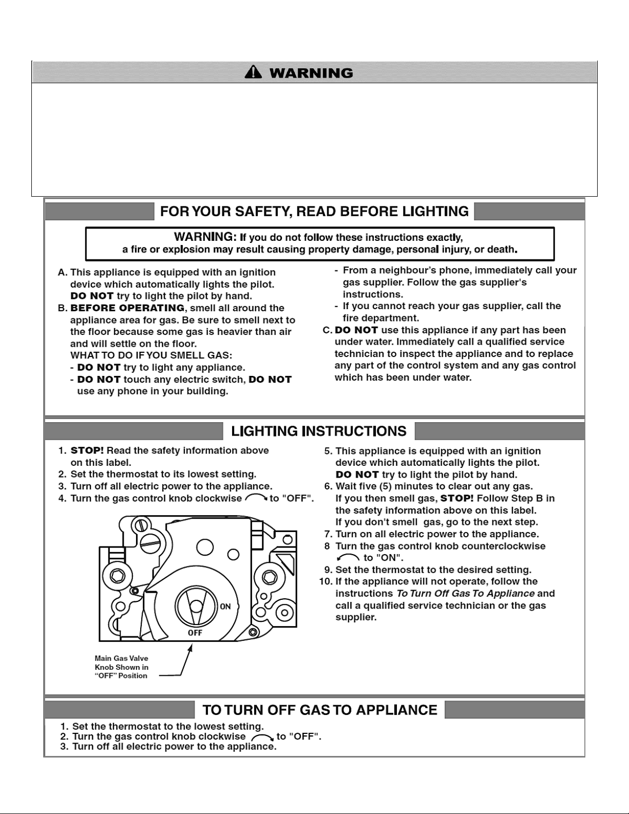
WHAT TO DO IF YOU SMELL GAS
Do not try to light any appliance.
Do not touch any electrical switch.
Do not use any phone in your building.
Immediately call your gas supplier from a neighbor’s phone. Follow the gas supplier’s instructions.
If you cannot reach your gas supplier, call the fire department. Installation and service must be provided by a qualified installer,
service agency, or the gas supplier.
LP-436 REV. 3.21.14
Page 3
3
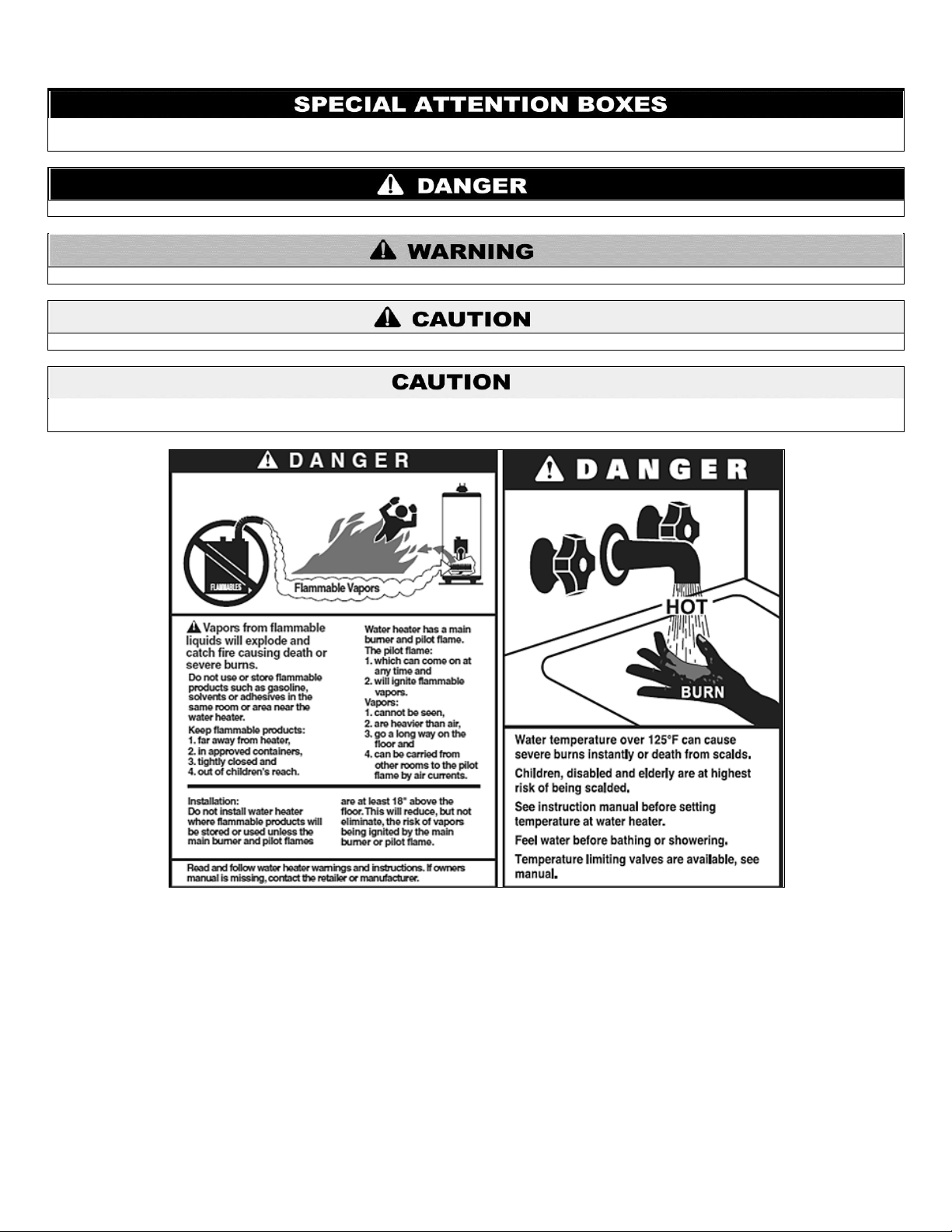
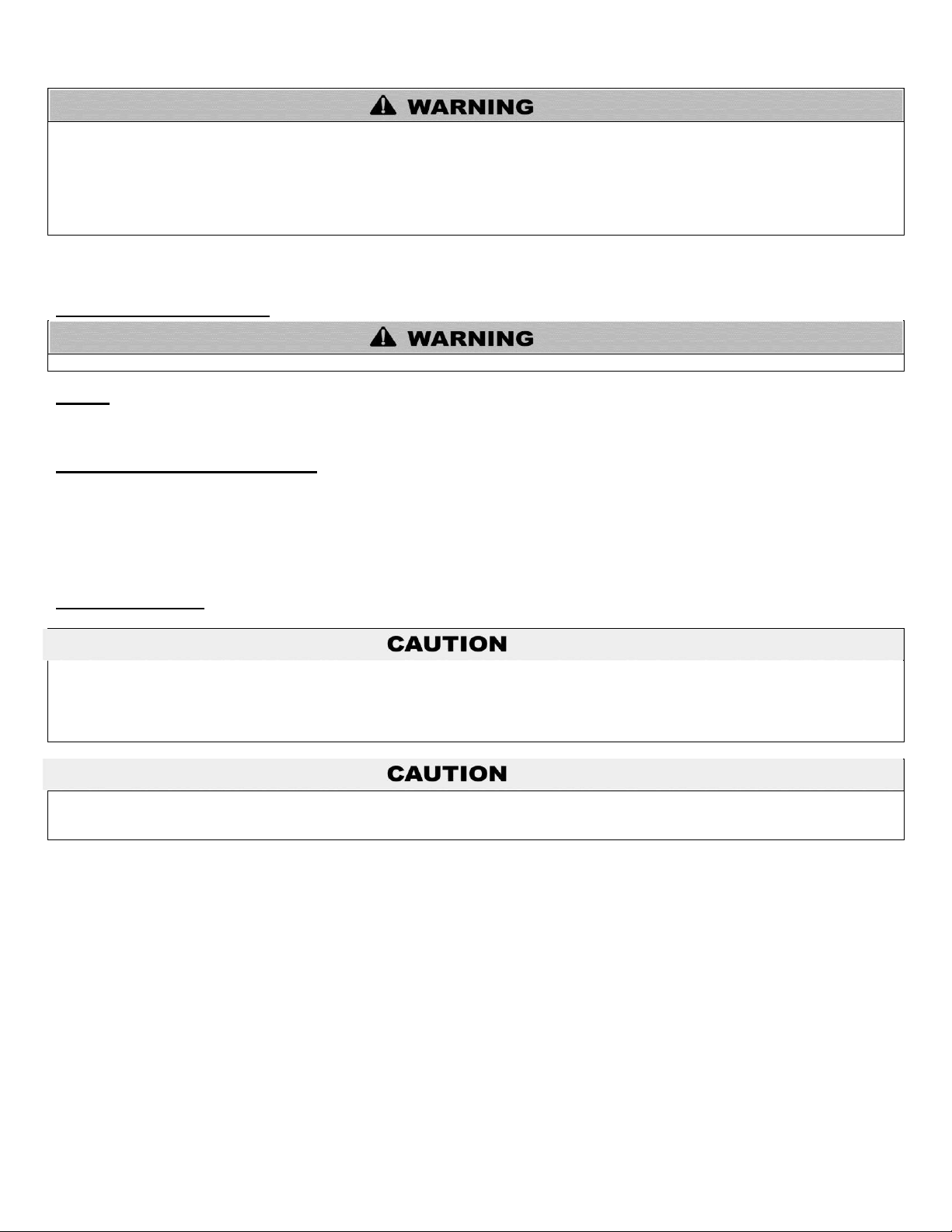
The following defined terms are used throughout this manual to bring attention to the presence of hazards of various risk
levels, or to important product information.
DANGER indicates an imminently hazardous situation which, if not avoided, will result in death or serious injury.
WARNING indicates a potentially hazardous situation which, if not avoided, could result in death or serious injury.
CAUTION indicates a potentially hazardous situation which, if not avoided, may result in minor or moderate injury.
CAUTION used without the safety alert symbol indicates a potentially hazardous situation which, if not avoided, may result in property
damage.
FOREWORD
This manual is intended to be used in conjunction with other literature provided with the Commercial Gas-Fired Water Heater. This
includes all related control information. It is important that this manual, all other documents included with this system, and additional
publications including the National Fuel Gas Code, ANSI Z223.1 / NFPA 54 (in Canada – CGA No. B149), be reviewed in their entirety
before beginning any work.
Installation should be made in accordance with the regulations of the local code authorities and utility companies which pertain to this
type of water heating equipment.
LP-436 REV. 3.21.14
Page 4
FOR THE INSTALLER
This manual must only be used by a qualified heating installer/service technician. Read all instructions in this manual before installing.
Perform steps in the order given. Failure to comply could result in severe personal injury, death or substantial property damage.
INSTALLER – Read all instructions in this manual before installing. Perform steps in the order given.
USER – This manual is for use only by a qualified heating installer/service technician. Have this heater serviced/inspected by a
qualified service technician annually.
FAILURE TO ADHERE TO THE GUIDELINES ON THIS PAGE CAN RESULT IN SUBSTANTIAL PROPERTY DAMAGE, SEVERE
PERSONAL INJURY, OR DEATH.
This appliance must be installed by qualified and licensed personnel. The installer should be guided by the instructions furnished with
the boiler, and with local codes and utility company requirements. In the absence of local codes, preference should be given to the
National Fuel Gas Code, ANSI Z223.1-2002.
INSTALLATIONS MUST COMPLY WITH:
Local, state, provincial, and national codes, laws, regulations and ordinances.
The latest version of the National Fuel Gas Code, ANSI Z223.1, from American Gas Association Laboratories, 8501 East Pleasant
Valley Road, Cleveland, OH 44131.
In Canada – CGA No. B149 (latest version), from Canadian Gas Association Laboratories, 55 Scarsdale Road, Don Mills, Ontario,
Canada M3B 2R3. Also, Canadian Electrical Code C 22.1, from Canadian Standards Association, 5060 Spectrum Way, Suite 100,
Mississauga, Ontario, Canada L4W 5N6.
Code for the installation of Heat Producing Appliances (latest version), from American Insurance Association, 85 John Street, New
York, NY 11038.
The latest version of the National Electrical Code, NFPA No. 70.
NOTE: The gas manifold and controls met safe lighting and other performance criteria when undergoing tests specified in ANSI
Z21.10.3 – latest edition.
4
TABLE OF CONTENTS
PART 1 – GENERAL SAFETY INFORMATION .......................................................................................................................... 4
A. PRECAUTIONS .......................................................................................................................................................................... 4
B. IMPROPER COMBUSTION ........................................................................................................................................................ 5
C. GAS ............................................................................................................................................................................................ 5
D. WHEN SERVICING THE HEATER ............................................................................................................................................. 5
E. WATER QUALITY ....................................................................................................................................................................... 5
F. OPTIONAL EQUIPMENT ............................................................................................................................................................ 6
PART 2 – INSTALLATION INSTRUCTIONS ............................................................................................................................... 7
PART 3 – OPERATING INSTRUCTIONS.................................................................................................................................. 19
PART 4 – GENERAL MAINTENANCE ...................................................................................................................................... 20
PART 5 – TROUBLESHOOTING GUIDE .................................................................................................................................. 25
MAINTENANCE NOTES .................................................................................................................................................................. 33
HTP CUSTOMER INSTALLATION RECORD FORM...................................................................................................................... 34
PART 1 – GENERAL SAFETY INFORMATION
A. PRECAUTIONS
LP-436 REV. 3.21.14
Page 5
If the heater is exposed to the following, do not operate until all corrective steps have been made by a qualified serviceman:
1. FIRE
2. DAMAGE
3. WATER
Any claims for damage or shortage in shipment must be filed immediately against the transportation company by the consignee. DO
NOT install or attempt to repair any damaged component or parts. If you detect any damage, contact the dealer where the water heater
was purchased or the manufacturer listed on the warranty.
Do not obstruct the flow of combustion and ventilating air. Adequate air is necessary for safe operation.
Chemical imbalance of the water supply may affect efficiency and cause severe damage to the water heater and associated equipment.
HTP recommends having water quality professionally analyzed to determine whether it is necessary to install a water softener. It is
important that the water chemistry on both the domestic hot water and central heating sides are checked before installing the water
heater, as water quality will affect the reliability of the system. Failure of a water heater due to lime scale build-up on the heating
surface, low pH, or other chemical imbalance IS NOT covered by the warranty.
Operating temperatures above 135oF will further accelerate the build-up of lime scale on the heating surface and may shorten the
service life of the water heater. Failure of a heat exchanger due to lime scale build-up on the heating surface, low pH, or other chemical
imbalance IS NOT covered by the warranty.
DO NOT USE THIS APPLIANCE IF ANY PART HAS BEEN UNDERWATER. Immediately call a qualified service technician. Replace
any part of the control unit that has been under water.
B. IMPROPER COMBUSTION
C. GAS
Should overheating occur or gas supply fail to shut off, turn off the manual gas control valve to the water heater. Ensure that the type of
gas supplied corresponds to that which is marked on the rating plate and main gas valve of the water heater.
D. WHEN SERVICING THE HEATER
To avoid electric shock, disconnect electrical supply before performing maintenance.
To avoid severe burns, allow heater to cool.
Do not use petroleum-based cleaning or sealing compounds in a heater system. Gaskets and seals in the system may be
damaged. This can result in substantial property damage.
Do not use “homemade cures” or “heater patent medicines”. Substantial property damage, damage to heater, and/or serious
personal injury may result.
5
E. WATER QUALITY
Water Chemistry
Outlined on the following page are water quality parameters which need to be met in order for the system to operate efficiently for many
years.
Water Hardness
Water hardness is mainly due to the presence of calcium and magnesium salts dissolved in water. The concentration of these salts is
expressed in mg/L, ppm, or grains per gallon as a measure of relative water hardness. Grains per gallon is the common reference
measurement used in the U.S. water heater industry. Hardness expressed as mg/L or ppm may be divided by 17.1 to convert to grains
per gallon. Water may be classified as very soft, slightly hard, moderately hard, or hard based on its hardness number. The minerals in
the water precipitate out as the water is heated and cause accelerated lime scale accumulation on a heat transfer surface. This lime
scale build-up may result in premature failure of the heat exchanger. Operating temperatures above 135oF will further accelerate the
build-up of lime scale on the heating surface and may shorten the service life of the water heater.
Water that is classified as hard and very hard must be softened to avoid heat exchanger failure.
LP-436 REV. 3.21.14
Page 6

CLASSIFICATION
MG/L OR PPM
GRAINS/GAL
Soft
0 – 17.1
0 - 1
Slightly Hard
17.1 – 60
1 – 3.5
Moderately Hard
60 – 120
3.5 – 7.0
Hard
120 – 180
7.0 – 10.5
Very Hard
180 and over
10.5 and over
If the hardness of the water exceeds the maximum level of 7 grains per gallon, water should be softened to a hardness level no lower
than 5 grains per gallon. Water softened as low as 0 to 1 grain per gallon may be under-saturated with respect to calcium carbonate,
resulting in water that is aggressive and corrosive.
pH of Water
pH is a measure of relative acidity, neutrality or alkalinity. Dissolved minerals and gases affect water pH. The pH scale ranges from 0 to
14. Water with a pH of 7.0 is considered neutral. Water with a pH lower than 7 is considered acidic. Water pH higher than 7 is
considered alkaline. A neutral pH (around 7) is desirable for most potable water applications. Corrosion damage and heater failures
resulting from water pH levels of lower than 6 or higher than 8 ARE NOT covered by the warranty. The ideal pH range for water
used in a storage tank or a water heater system is 7.2 to 7.8.
Total Dissolved Solids
Total Dissolved Solids (TDS) is a measurement of all minerals and solids dissolved in a water sample. The concentration of total
dissolved solids is usually expressed in parts per million (ppm).
Water with a high TDS concentration will greatly accelerate lime and scale formation in the hot water system. Most high TDS
concentrations precipitate out of the water when heated. This can generate a scale accumulation on the heat transfer surface that will
greatly reduce the service life of a water heater. This scale accumulation can also impede the ability of the heat exchanger to transfer
heat into the water. A heat exchanger damaged or blocked by lime/scale accumulation must be replaced.
The manufacturer of the water heater has no control of water quality, especially TDS levels in your system. Total dissolved solids in
excess of 2,000 ppm will accelerate lime and scale formation in the heat exchanger. Heat exchanger failure due to total dissolved solids
in excess of 2,000 ppm is a non-warrantable condition. Failure of a water heater due to lime scale build up on the heating surface
IS NOT covered by the warranty.
Hardness: 7 grains
Chloride levels: 100 ppm
pH levels: 6-8
TDS: 2000 ppm
Sodium: 20 mGL
6
F. OPTIONAL EQUIPMENT
Below is a list of optional equipment available from HTP. These additional options may be purchased through your HTP distributor.
High Altitude Kit
Part # 8800P-024 – 125 kBTU
Part # 8800P-025 – 150 kBTU
Part # 8800P-026 – 199.9 kBTU
Part # 8800P-027 – 250 kBTU
Part # 8800P-028 – 300 kBTU
Power Venter
Part # 6060-200 – 125 kBTU
Part # 6060-201 – 150 – 300 kBTU models
Vent Termination Kit
Part # 6060-202 – 125 kBTU
Part # 6060-203 – 150 – 300 kBTU models
LP-436 REV. 3.21.14
Page 7
PART 2 – INSTALLATION INSTRUCTIONS
MODEL
STORAGE
CAPACITY
GALLONS (LITERS)
FUEL
TYPE
INPUT
(BTU)
RECOVERY 90oF / 50oC
GALLONS (LITERS) PER
HOUR
SHIPPING WEIGHT
LBS. (EST.)
CG125N73
72 (272)
N
125,000
135 (511)
429
CG150N73
70 (265)
150,000
162 (613)
CG199N73(X)
68 (257)
199,900
215 (814)
CG250N65
60 (227)
250,000
269 (1018)
465
CG300N65
55 (208)
300,000
323 (1223)
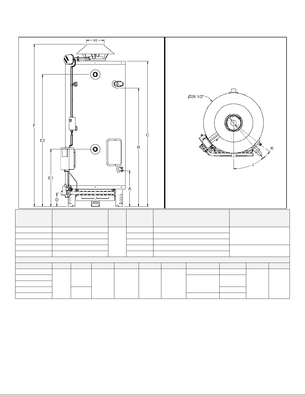
MODEL DIMENSIONS IN INCHES
MODEL
A B C D E1
E2 F H J K
CG125N73
15 ¾
52 ½
64 1/8
5 7/8
25 ¼
58 ¼
69 ¼
5
40.3o
51.2o
CG150N73
70 7/8
6
CG199N73(X)
CG250N65
52 1/8
7
CG300N65
71 5/8
8
Specifications and Dimensions
7
Table 1 – Specifications and Dimensions – NOTE: All Water Heaters Shipped to Operate on Natural Gas – A suffix of “X”
denotes model set for Low NOx operation
Location
This water heater should be located in a clean, dry location, as close as possible to the chimney and to the main use of hot water. This
location must not be subject to freezing temperatures. Make sure the cold water piping is not located directly above the main gas valve
or any other electrical control. This will prevent water and condensation from dripping on the main gas valve during installation and
operation.
The water heater should be positioned so there is easy access to the main gas valve, flue damper, junction box, temperature and
pressure relief valve, and drain valve. Space must be provided at the front of the water heater so that the burner tray assembly can
slide out for service.
LP-436 REV. 3.21.14
Page 8
The water heater must be located close to a suitable freeflowing floor drain. Where a floor drain is not adjacent to the
water heater, a suitable drain pan must be installed under the
water heater. See Figure 10 for proper installation. The drain
pan should be at least 4” (10.2 cm) larger than the diameter of
the water heater, and at least 1” (2.5 cm) deep, providing
access to the drain valve. This pan must not restrict the flow of
ventilation and combustion air. This pan must be piped to a
suitable drain to prevent damage to property in the event of a
water leak from the piping, the temperature and pressure relief
valve, or the water heater. Failure to follow this warning could
result in property damage, severe personal injury, or death.
This water heater IS NOT design certified for installation in a
manufactured (mobile) home or for installation outdoors.
Failure to follow this warning could result in property damage,
severe personal injury, or death.
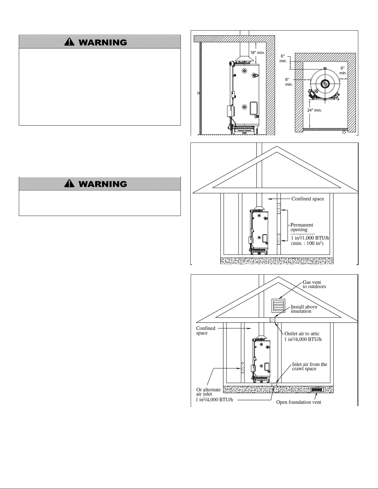
Figure 1 – Minimum Clearances
Figure 2 – All Air from Inside the Building
Figure 3 – Communicating Directly with the Outdoors
All water heaters will leak. The manufacturer, based on
national building codes, has given the necessary
instructions to prevent damage to the building. Under no
circumstances is the manufacturer to be held liable for any
water damage in connection with this water heater. See
Figure 10 for proper installation.
8
This water heater is approved for installation on either a
combustible or non-combustible floor. However, should this water
heater be installed directly on carpeting, the carpeting must be
protected by a wood or metal panel beneath the water heater.
This panel must extend at least 3” (7.6 cm) beyond the width and
depth of the water heater. Should the water heater be installed in
an alcove or closet, the entire floor area must be covered by the
panel. The panel must be strong enough to carry the weight of the
water heater when it is full of water (CG-73 = 1040 lbs., CG-65 =
1010 lbs.)
Minimum Clearances
The minimum clearances from combustible materials for this
water heater are: 6” (15.2 cm) from the sides and rear, 24” (61
cm) from the front, and 18” (45.7 cm) from the top.
Combustion and Ventilation Air Supply
In order for the water heater to operate properly, it must be
supplied with an uninterrupted flow of clean combustion and
ventilation air. The area around the water heater must always be
kept clear so that the flow of combustion and ventilation air is not
blocked. An inadequate supply of air to the water heater will
produce a bright yellow burner flame, causing sooting in the
combustion chamber, on the burners, and in the flue tubes. This
can result in damage to the water heater and serious bodily injury
if not corrected.
Combustion and ventilation air requirements are determined by
the water heater location. Water heaters are installed in either
open (unconfined) spaces or smaller (confined) spaces, such as
closets or small rooms.
Requirements for Unconfined Spaces
An unconfined space is an area with at least 50 cubic feet for each 1,000 BTU/H of the total input rating for all gas-fired appliances
installed in that space. Water heaters installed in unconfined spaces do not usually require outdoor air to function properly. However, in
buildings with tight construction (heavy insulation, vapor barriers, weather stripping, etc.), and particularly in modern buildings,
LP-436 REV. 3.21.14
Page 9
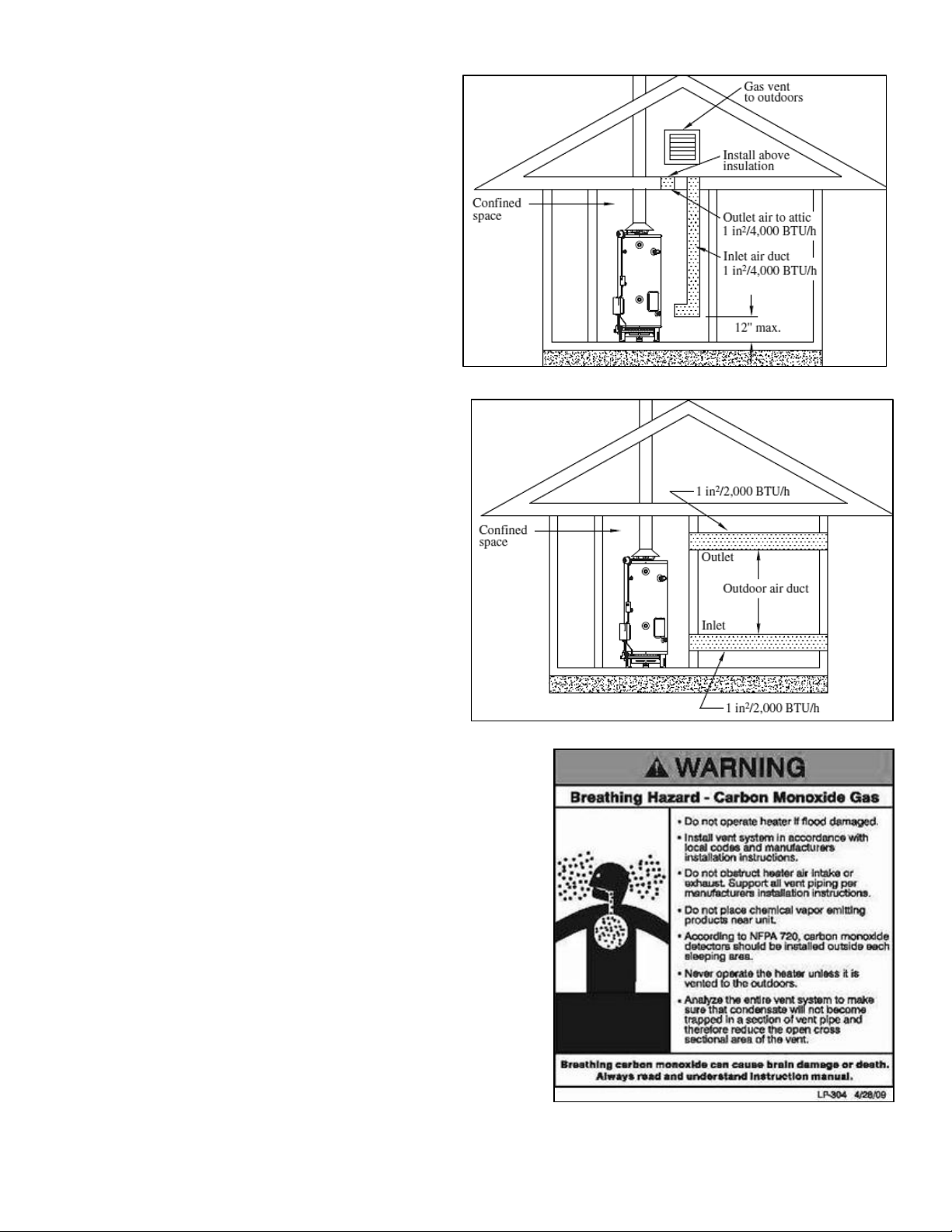
additional fresh air may need to be provided. For instructions
Figure 4 – Communicating with the Outdoors through Vertical Ducts
Figure 5 – Communicating with the Outdoors through Vertical Ducts
on obtaining additional air supply, see the requirements for
confined spaces.
Requirements for Confined Spaces
A confined space is an area where the volume is less than 50
cubic feet for each 1,000 BTU/H of the total input rating for all
gas appliances installed in that space. Water heaters installed
in confined spaces require additional combustion and
ventilation air. This can be provided in two ways:
1. All Air from Inside the Building
The confined space shall be provided with two permanent
openings communicating directly with one or more rooms of
sufficient volume, so that the combined volume of all spaces
meets the criteria for an unconfined space. The total input
rating of all gas appliances installed in the combined space
shall be considered in making this determination.
Each opening shall have a minimum free area of one
square inch per 1,000 BTU/H of the total input rating of all gas
appliances in the confined space, but not less than 100 square
inches. One opening shall commence within 12” (30.5 cm) of the
top and one within 12” (30.5 cm) of the bottom of the enclosure.
See Figure 2.
2. All Air from Outdoors
The confined space shall be provided with two permanent
openings, one commencing within 12” (30.5 cm) of the top and
one commencing within 12” (30.5 cm) of the bottom of the
enclosure. The openings shall communicate directly, or by
ducts, with the outdoors or spaces (crawl or attic) that freely
communicate with the outdoors.
a. When communicating directly with the outdoors, each
opening shall have a minimum free area of one square inch per
4,000 BTU/H of the total input rating of all gas appliances in the
enclosure. See Figure 3.
b. When communicating with the outdoors through vertical
ducts, each opening shall have a minimum free area of
one square inch per 4,000 BTU/H of the total input rating of all gas appliances
in the enclosure. See Figure 4.
c. When communicating with the outdoors through horizontal ducts, each
opening shall have a minimum free area of 1 square inch per 2,000 BTU/H of
the total input rating of all gas appliances in the enclosure. See Figure 5.
When ducts are used, they shall be of the same cross-sectional area as the
free area of the openings to which they connect. The minimum short side
dimension of rectangular air ducts shall not be less than 3” (7.62 cm).
Louvers and Grilles
In calculating free area for ventilation and combustion air supply openings,
consideration must be given to the blocking effect of louvers, grilles, or
screens protecting the openings. Screens must not be smaller than ¼” (6.4
mm) mesh. If the free area through a particular design of louver or grille is
known, it should be used in calculating the size of opening required to provide
the free area specified. If the design and free area is not known, it may be
assumed the wood louvers and grilles will allow 20-25% free area and metal
louvers and grilles will allow 60-75% free area. Louvers and grilles must be
installed in the open position or interconnected with the water heater so that
they are opened automatically during water heater operation.
9
LP-436 REV. 3.21.14
Page 10
10
When installing the venting system, make sure to follow all local codes, or, in the absence of local codes, National Fuel Gas Code,
ANSI Z223.1/NFPA 54 in the United States, or CAN/CSA B149.1, National Gas and Propane Installation Code in Canada. Never
operate the water heater unless it is properly ventilated to the outdoors and has adequate air supply for proper operation. Failure to
properly install the venting system could result in property damage, personal injury, or death.
High heat sources (sources generating heat 100oF / 37oC or greater, such as stove pipes, space heaters, etc.) may damage plastic
components of the water heater as well as plastic vent pipe materials. Such damages ARE NOT covered by warranty. It is
recommended to keep a minimum clearance of 8” from high heat sources. Observe heat source manufacturer instructions, as well as
local, state, provincial, and national codes, laws, regulations and ordinances when installing this water heater and related components
near high heat sources.
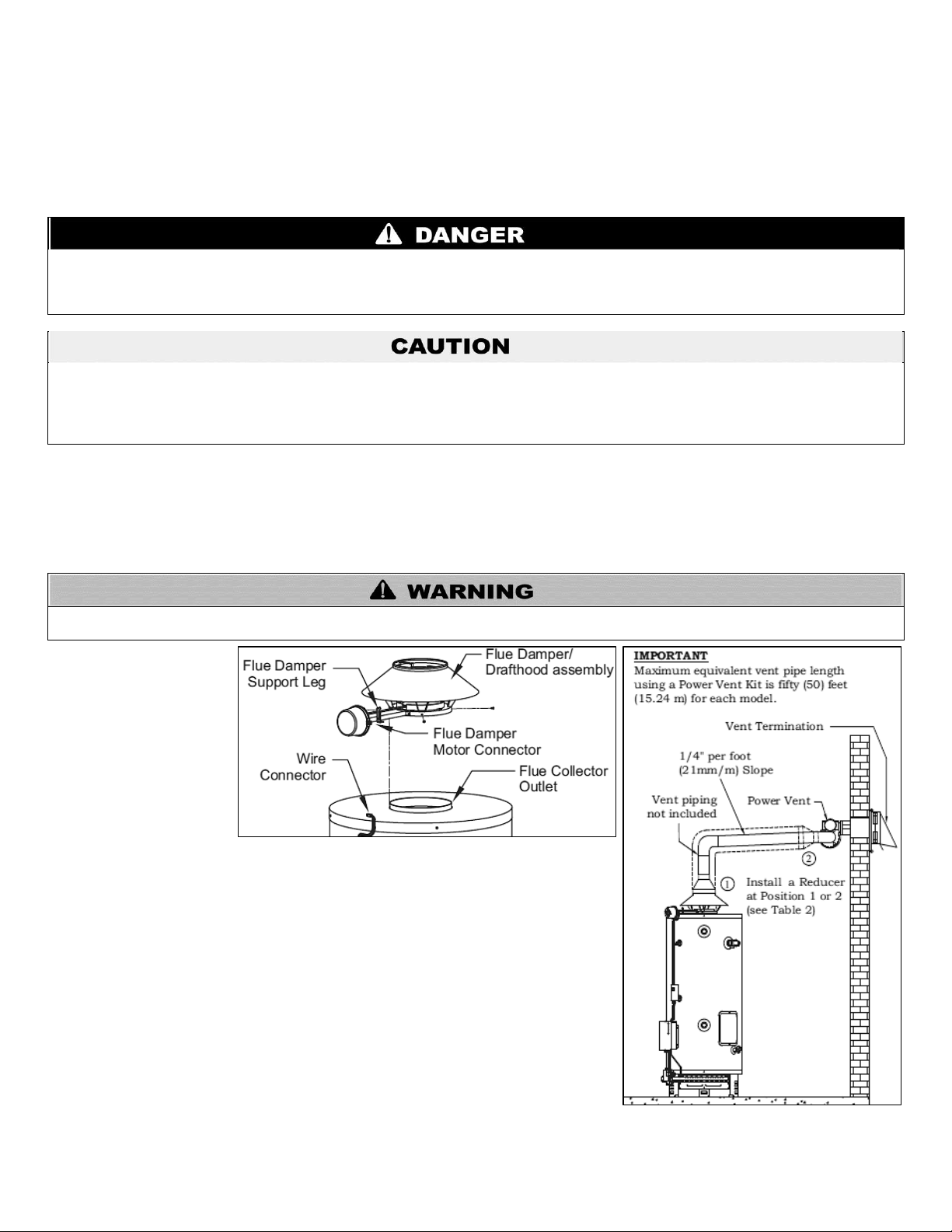
DO NOT modify the flue damper / drafthood assembly in any way. DO NOT turn on the electrical power to the water heater until the flue
damper / drafthood assembly is installed. Failure to follow these instructions can result in property damage, personal injury, or death.
Figure 6 – Flue Damper/Drafthood Assembly
Figure 7 – Power Vent Kit Installation
Corrosive Atmospheres
If this water heater is to be installed in a beauty shop, barber shop, photo processing lab, dry cleaning establishment, a building with an
indoor pool, or near a chemical storage area, it is imperative that the combustion and ventilation air be drawn from outside these areas.
These particular environments contain products such as aerosol sprays, detergents, bleaches, cleaning solvents, refrigerants, and
other volatile compounds that, in addition to being highly flammable, become highly corrosive acid compounds when burned. Exposure
to such compounds can be hazardous and lead to premature product failure. Should the water heater fail due to exposure to such a
corrosive atmosphere, the warranty is void.
Venting
Automatic Flue Damper/Drafthood Assembly
The flue damper/drafthood assembly has been shipped from the factory in a separate box attached to this water heater. Before
installing the flue damper/drafthood assembly, verify that it is the correct model for this water heater (the CG125N73 uses a 5” flue
damper, all other 73 gallon models use a 6” flue damper; CG250N65 uses a 7” flue damper, all other 65 gallon models use an 8” flue
damper). If the wrong assembly has been shipped or is missing completely, immediately contact the dealer where the water heater was
purchased. Never operate this water heater without the manufacturer’s flue damper/drafthood assembly installed.
When installing the water
heater, make sure the
location allows clear
viewing of the flue
damper. When the damper
is in the open position, the
paddle is perpendicular to
the water heater. The flue
damper must be in an
open position when the
water heater’s burners are
operating.
To install the flue damper/drafthood assembly, use the following instructions and secure
all pieces with the provided sheet metal screws. See Figure 6.
1. Remove the flue damper/drafthood assembly from its packaging.
2. Center the assembly over the flue collector outlet.
3. Rotate the assembly so that the wire connector on the water heater can plug into the
flue damper motor connector.
4. Use the wire connector to secure the assembly to the flue connector.
5. Install the flue damper support leg on the assembly.
6. Secure the assembly to the top of the water heater.
7. Plug the wire connector on the water heater into the flue damper motor connector.
Venting System
The venting system must be attached to the drafthood to connect the water heater to the
gas vent or chimney. The vent pipe connecting the water heater must be of the same
size as the drafthood outlet. It is highly recommended to install this water heater on a
LP-436 REV. 3.21.14
Page 11

11
When using an optional power vent kit, the power venter must be properly secured against the outside wall. Failure to properly secure
the power venter can result in exhaust gas leak, property damage, personal injury, or death.
separate venting system from other appliances. In some installations, proper venting may require the use of a larger diameter vent pipe
and/or combined venting with other appliances. Consult the vent tables in the ANSI Z223.1/NFPA 54 in the United States, of CAN/CSA
B149.1 National Gas and Propane Installation Code, in Canada, to correctly size the vent pipe.
When connecting the vent pipe to the water heater, the following instructions must be followed:
Install the vent pipe in such a way as to avoid any unnecessary bends that could create resistance to the flow of combustion
gases.
The length of the horizontal vent pipe must not exceed 75% of the vertical vent pipe height and never exceed 20’ (6.1 m).
All horizontal runs must have a minimum rise of ¼” (21 mm/m) per foot of run. See Figure 7.
All joints must be securely fastened with sheet metal screws or other approved means.
All single wall vent piping must maintain a minimum of 6” (15.2 cm) of clearance from combustible materials.
Venting systems made with single wall piping cannot pass through any attic, inside wall, crawl space, confined space, or any
floor.
The vent piping must be accessible for inspection, cleaning, and replacement.
Optional Side Wall Power Vent Kits
This water heater is approved for installation with a TjernlundTM side wall power vent kit. See Figure 7. This kit can be installed as part
of a new installation or retrofitted onto an existing installation. The kit consists of a power venter and vent termination assembly. See
Table 2 and Figure 9. Vent piping is not included. Before beginning the installation of the power vent kit, make sure that it is the
appropriate kit for your model water heater. See Table 2. Make sure that the water heater is located so all vent terminal clearances will
be respected. See Figure 8. Maximum equivalent vent pipe length is 50’ for each model. For complete instructions on the side wall vent
kit installation, consult the manual that comes with the kit.
LP-436 REV. 3.21.14
Page 12

12
WHEN USING A POWER VENT KIT, THE VENT TERMINATION MUST HAVE:
US Installations
1
Canadian Installations
2
A) Clearance above grade, veranda, porch, deck, or balcony
12”
30 cm
B) Clearance to window or door that may be opened
3’
1.2 m below or to the side of opening; 30
cm above opening
C) Clearance to permanently closed window
*
*
D) Vertical Clearance to ventilated soffit located above the terminal within a horizontal
distance of 2’ from the center line of the terminal
*
*
E) Clearance to unventilated soffit
*
*
F) Clearance to outside corner
*
*
G) Clearance to inside corner
*
*
H) Clearance to each side of center line extended above meter/regulator assembly
3’
*
I) Clearance to service regulator vent outlet
3’
*
J) Clearance to non-mechanical air supply inlet to building or the combustion air inlet
to any other appliance
3’
1.2 m below or to the side of opening; 30
cm above opening
K) Clearance to a mechanical air supply inlet
6’
91 cm above if within 3 m horizontally
L) Clearance above paved sidewalk or paved driveway located on public property
7’
†
2.13 m
M) Clearance under veranda, porch, deck, or balcony
12”
‡
*
MODEL
KIT#
MOTOR
DIMENSIONS (INCHES)
VENT HOOD
ROUGH-IN
INLET /
OUTLET
Watts
Amps
A B C D E F G H I
J
CG125N73
1
95
1.26
7
7/8
7
11
4
7½
(sq)
7
1/8
13
(sq)
8
5/8
7 3/8
11
8
(sq)
4
CG150N73 to
CG300N65
2
224
1.51
9¼
8½
11½
6
8½
(dia)
7
7/8
12
(sq)
9½
9½
10
9
(dia)
6
Figure 8 – Vent Installation Detail
Table 2 – Power Vent Kit Installation Requirements
1
In accordance with current ANSI Z223.1/NFPA 54 National Fuel Gas Code.
2
In accordance with the current CAN/CSA B149.1 National Gas and Propane Installation Code.
*Clearance in accordance with local installation codes and the requirements of the gas supplier.
†
Vent shall not terminate directly above a sidewalk or paved driveway located between two single family dwellings that serves both dwellings.
‡
Permitted only if veranda, porch, deck, or balcony is fully open on a minimum of two sides beneath the floor.
Table 3 – Power Venter Including Terminal - NOTES: Max vent length based on total of straight vent pipe plus 11’ for 6” dia. 90o elbow, 7’ for a
o
4” 90
elbow, 5’ for a 6” 45o elbow, 4’ for a 4” dia. 45o elbow, 4’ for a 8” to 6” reducer, and 5’ for a 6” to 4” reducer.
LP-436 REV. 3.21.14
Page 13

13
Power Venter
Vent Termination
Kit #1
Part # 6060-200
Part # 6060-202
Kit #2
Part # 6060-201
Part # 6060-203
MODEL
KIT
DRAFT
HOOD
OUTLET
VENT
SIZE
VENT
ADAPTER
VENT
REDUCER
LOCATION
CG125N73
1
5”
4”
5”-4”
1
CG150N73
2
6”
6”
Not Req.
-
CG199N73(X)
2
6”
6”
Not Req.
-
CG250N65
2
7”
6”
7”-6”
1
CG300N65
2
8”
6”
8”-6”
1
When the installation is complete, visually inspect the venting system to make sure that all joints are properly connected and all
instructions have been followed. Failure to properly install the venting system can result in property damage, personal injury, or death.
DO NOT plug the temperature and pressure relief valve or its discharge line. DO NOT remove the relief valve. Make sure the relief
valve is properly sized for the water heater. If the relief valve continuously discharges water, call a qualified service technician to correct
the problem. Failure to follow these instructions can result in property damage, personal injury, or death.
Figure 9 – Power Venter and Vent Termination
Table 4 – Power Venter and Vent Termination Part Numbers
Table 5 – Vent Sizing, By Model Number
NOTE: Vent Pipe is Not Included
Water Piping
Refer to Figure 10 for a typical installation. Use of this layout should provide a trouble-free installation for the life of the water heater.
Before making the plumbing connections, locate the COLD water inlet and the HOT water outlet. These fittings are both 1 ½” NPT male
thread. Install a shut-off valve close to the water heater in the cold water line. It is recommended that unions be installed in the cold and
hot water lines so that the water heater can be easily disconnected if service is required.
NOTE: It is recommended to use dielectric unions when connecting to the water heater.
When assembling the hot and cold piping, use food grade pipe joint compound and ensure all fittings are tight. It is imperative that open
flame is not applied to the inlet and outlet fittings, as heat will damage or destroy the plastic lined fittings. This will result in premature
failure of the fittings, which is not covered by warranty.
Temperature and Pressure Relief Valve
To protect from excessive pressure and/or temperature, the manufacturer has installed a temperature and pressure relief valve that
meets the requirements of the Standard for Relief Valves and Automatic Gas Shut-Off Devices for Hot Water Supply Systems, ANSI
Z21.22 in the United States, and CSA 4.4 in Canada. This relief valve has a maximum set pressure that does not exceed the
hydrostatic working pressure of the water heater (150 psi = 1,035 kPa) and a BTU/H rating equal to or greater than the input rating, as
shown on the water heater rating plate. It should never be plugged or removed from the opening marked for it on the water heater.
If this relief valve should need to be replaced, use only a new temperature and pressure relief valve. Never install an old or existing
relief valve, as it may be damaged or inadequate for the working requirements of the new water heater. This new relief valve must meet
all local codes, or, at minimum, the requirements listed above. Never install any other type of valve between the relief valve and the
water heater.
A discharge line must be installed into the relief valve. The discharge line:
Must not be smaller than the outlet pipe size of the relief valve.
Must not terminate less than 6” (15.2 cm) and not more than 12” (30.5 cm) above a floor drain.
Must not be restricted in any way. Do not thread, cap, or in any way restrict the end of this outlet.
Must be of a material capable of withstanding 193oF (90oC) without distortion.
Must be installed to allow complete drainage of the relief valve and discharge line.
Must terminate at an adequate free-flowing drain.
LP-436 REV. 3.21.14
Page 14

Pressure Build-Up in a Water System
NEVER operate the water heater unless it is completely full of water. Failure to follow this instruction can result in premature failure of
the water heater. Such failure IS NOT covered by warranty.
DO NOT attempt to use this water heater with any gas other than the type shown on the water heater rating plate. Failure to follow this
instruction can result in property damage, personal injury, or death.
NEVER use an open flame to test for gas leaks. A fire or explosion could occur, resulting in property damage, personal injury, or death.
High altitude orifices MUST BE installed for water heaters operating above 7,500 feet. Failure to follow this instruction can result in
property damage, personal injury, or death.
When the water heater operates, the heated water expands creating a pressure build-up. This is a natural function and is one of the
reasons for installing a temperature and pressure relief valve. If the cold water supply line has a built-in water meter, check valve, or
pressure-reducing valve, a suitable expansion tank must be installed to prevent pressure build-up or water hammer effect. Otherwise,
the warranty is void. See Figure 10. An indication of pressure build-up is frequent relief valve discharge. If the relief valve discharges
water on a continuous basis, it may indicate a malfunction of the relief valve and a qualified service technician must be called to have
the system checked and the problem corrected.
Filling the Water Heater
Check that all the water piping connections have been made. To fill the water heater:
1. Make sure that the water heater drain valve is closed by turning the knob clockwise.
2. Open the cold water supply manual shut-off valve. This valve must remain open as long as the water heater is in use. NEVER
operate the water heater with the cold water supply manual shut-off valve closed.
3. To make sure the water heater is completely full of water, open hot water faucets to let the air out of the water heater and
plumbing system. Leave the faucets open until a constant flow of water is obtained.
4. Check all of the plumbing connections to make sure there are no leaks.
Gas Connections
14
The gas piping must be installed as indicated in Figure 10. For the correct size of piping for this water heater, consult the National Fuel
Gas Code, ANSI Z223.1 / NFPA 54 in the United States, or CAN/CSA B149.1, National Gas and Propane Installation Code in Canada.
Only new piping with cleanly cut threads may be used, together with a suitable sealing compound that is approved for natural and
propane gases. It is mandatory that a readily accessible manual shut-off valve be installed in the gas supply line. The gas supply
manual shut-off valve must be close to the water heater. A drip leg (sediment trap) must be installed in the gas line ahead of the main
gas valve to prevent dirt from entering it. A union must be installed between the main gas valve and the gas supply manual shut-off
valve for easy maintenance of the water heater.
The water heater and its gas connection must be leak tested before placing the appliance into operation. To leak test the system:
1. Turn on the manual gas shut-off valve near the water heater.
2. Use a soapy water solution to test all connections and fittings for leaks. Bubbles indicate a gas leak.
3. Correct all leaks.
Make sure that the inlet pressure to the water heater does not exceed 14 inches of water column (3.5 kPa) for natural gases.
Pressures in excess of ½ pound per square inch (3.5 kPa) can damage the main gas valve, resulting in a fire or explosion from leaking
gas. For purposes of adjustment, the minimum inlet pressure is indicated on the water heater rating plate.
If any pressure testing of the gas line is undertaken at test pressures in excess of ½ psig (3.5 kPa), the water heater and its gas supply
manual shut-off valve must be disconnected from the gas supply piping system, and the end of the pipe sealed with a female cap. If the
testing is to be undertaken at a test pressure less than ½ psig (3.5 kPa), the gas supply manual shut-off valve must be closed.
NOTE: The input rating of the appliance is based on installation and operation at sea level up to elevations of 2,000 ft. Low NOx models
are certified to operate to 2,000 ft in altitude without adjustment.
Installation Instructions for Water Heaters Approved for Combination Space Heating and Potable Water Heating
When using a water heater for combination space and potable water heating, the instructions provided in this manual and the airhandling unit must be respected, with particular attention paid to the following:
LP-436 REV. 3.21.14
Page 15

All piping and components that are used in the system must be of a nonferrous type suitable for potable water. This also
This water heater uses an external electrical source for power. It must be electrically grounded in accordance with all local codes, or, in
the absence of local codes, the latest edition of the National Electrical Code, ANSI/NFPA 70 in the United States, or CAN/CSA C22.1,
Canadian Electrical Code, in Canada. Failure to properly ground the water heater can result in property damage, personal injury, or
death.
applies to any sealant used.
The water heater must not be connected to any system that has been previously used for non-potable water heating. This
includes piping because existing piping may have been treated with chemicals for cleaning or sealing the system in the past.
If this water heater is to be used for space heating, make sure all safety codes are respected. Pay special attention to safety
valve pressure and expansion tanks.
Do not use toxic chemicals to clean the potable water heating system.
Where water temperature in excess of 140oF (60oC) is required for a space heating application, a mixing valve must be
installed in the potable side of the system. This will temper the water and reduce the risk of scalding.
If the incoming water line to the heater is equipped with a check valve, water meter, or pressure-reducing valve, an expansion
tank must be installed in the system. This will prevent weeping from the water heater relief valve and premature failure of the
heater due to expansion of water during the heating cycle.
Before acquisition of a water heater for space heating, it is necessary to have the area of intended use sized by a qualified
technician. This will ensure that an adequate water heating capacity will be available for both heating and potable water
supply, and that the application will meet all local codes and public utility requirements.
15
Figure 10 – Typical Installation
Wiring
Before lighting your water heater, check that all of the wires have been installed correctly. See Figure 12. Inspect local wiring for defects
before installing this product. Verify that all wiring connections are properly secured. If wiring on the product appears “loose” or
LP-436 REV. 3.21.14
Page 16

damaged when received, immediately call HTP, Inc. customer service. If instructed to replace any of the original wiring, use only 18
If the water heater requires servicing, label all wires prior to
disconnecting. Verify all wiring connections before
relighting the water heater. Wiring errors can result in
property damage, personal injury, or death. Damages to
this product due to improper wiring ARE NOT covered
under warranty.
Settings on Power Venter
Voltage: 24 Volts
Pre-purge: 0 sec.
Post-Purge: 2 min.
Figure 11 – Wiring Power Vent Kit Detail
AWG type or greater wire approved for 221oF (105oC).
If you are installing a side wall power vent kit, use the following instructions to connect the power venter to the water heater. See
Figures 11 and 12.
1. In the electrical box of the water heater, remove the jumper between positions 3 and 4 on the terminal block.
2. Install the wires from the power venter control board to the positions on the terminal block in the electrical box of the water
heater.
If the power venter has been bought through a wholesaler, some settings need to be changed on the control board before putting the
water heater into operation. The voltage needs to be set at 24 Volts. This can be done by moving the red voltage jumper on the 24V
prongs. For detailed instructions on how to adjust the power vent settings, consult the Owner’s
Manual that comes with the Tjernlund Power Venter.
If the power venter has been bought directly from HTP, the settings have been factory adjusted to
match the specifications of the water heater. A label will be affixed on the box stating that it was
factory adjusted to HTP commercial gas water heater specifications.
16
LP-436 REV. 3.21.14
Page 17

17
LP-436 REV. 3.21.14
Page 18

18
LP-436 REV. 3.21.14
Page 19

Installation Checklist
DO NOT LIGHT this water heater if:
It is not full of water.
The gas supplied does not match the type listed on the rating plate.
The flue damper/drafthood assembly has not been installed.
Gasoline or any other flammable vapors or liquids have been stored in the vicinity of the water heater.
Failure to follow these instructions could result in property damage, serious personal injury, or death.
Location
Is the water heater located close to the chimney or the gas vent and the main use of hot water?
Is the water heater protected from freezing temperatures?
Has a drain pan been installed and piped to a free-flowing drain?
Is the main gas valve accessible for servicing?
Have clearances from combustible materials been observed?
Combustion and Ventilation Air Supply
Is the area around the water heater clean and properly ventilated?
Is the fresh air supply free of corrosive elements and flammable vapors?
Does the water heater have access to enough fresh combustion air?
Have the fresh air openings been sized correctly and has consideration been given to the blocking effect of louvers and
grilles?
Venting
Has the manufacturer’s supplied flue damper/drafthood assembly been installed correctly?
Is the vent piping made of an approved material and sized correctly?
Have all horizontal runs of vent pipe been installed with a minimum rise of ¼” per foot of run?
Has all vent piping been secured with sheet metal screws?
Water Piping
Has a temperature and pressure relief valve been installed?
Does this valve have a discharge line installed, and is it piped to a free-flowing drain?
Have all the piping connections been properly installed, and are they leak free?
Is the water heater full of water?
Gas Connections
Is the gas supplied to the water heater the same type indicated on the water heater rating plate (Natural)?
Has the gas line been installed with a manual shut-off valve, union, and drip leg?
Is the gas piping large enough and made of an approved material?
Have all connections been made with an approved joint compound?
Has the gas piping been tested for leaks with a soap and water solution?
Wiring
Has the wiring been properly installed?
Have the electrical connections been checked, and are they secure?
Is the water heater electrically grounded?
19
PART 3 – OPERATING INSTRUCTIONS
Lighting the Water Heater
Before lighting or relighting the water heater, make sure you have read and understood all of the instructions
and warnings in this manual and on the water heater. If you have any questions about lighting the water heater,
immediately contact a qualified installer, service agency, or gas supplier.
LP-436 REV. 3.21.14
Page 20

Drafthood Operation
The higher the temperature setting, the greater the risk of scalding. Hot water
can cause third degree burns in 1 second at 160oF (71oC), 5 seconds at 150oF
(65oC), and 30 seconds at 130oF (54oC). In households where there are
children, physically challenged individuals, or elderly persons, mixing valves
for point of use are necessary as a means of reducing the scalding potential of
hot water. Failure to install a mixing valve can result in serious personal injury
or death.
Should overheating occur or the gas supply fail to shut off, close the gas supply manual shut-off
valve. Failure to follow this instruction can result in serious personal injury or death.
DO NOT STORE or use gasoline or other flammable vapors or liquids around the water heater.
DO NOT BLOCK or in any way restrict the flow of fresh air to the water heater.
DO NOT PUT or store any objects on the top of the water heater.
Failure to follow these instructions can result in property damage, personal injury, or death.
Figure 14 - Thermostat
It is important to check that the ventilation system is working properly once the water
heater main burner has been lit. Wait 10 minutes after lighting the burner. Then
introduce a match or candle around the opening of the drafthood. If the flame is
drawn towards the opening, this indicates proper ventilation. If the flame flutters or is
blown out, combustion gases are escaping from the drafthood opening. If this
occurs, shut the water heater off immediately and locate the problem. Do not try
and operate the water heater again until you are satisfied that the problem has
been corrected.
Water Temperature Regulation
The water temperature for all models is controlled by a thermostat with two sensing
elements. One sensor is located near the top of the tank and the other is near the
center. The thermostat is factory adjusted to its lowest temperature setting. To
adjust the water temperature, insert a small flat head screwdriver into the slotted
screw located in the hole on the front of the thermostat. See Figure 14. Turn the
temperature dial to the desired setting. To maximize the efficiency of the water
heater and reduce the risk of scalding, it is recommended that the dial be adjusted
to the lowest setting that produces an acceptable hot water supply. The dial may be
set from 100oF to 180oF (38oC to 82oC).
When hot water is drawn from the tank in frequent short bursts, a condition known as “stacking” is
created. “Stacking” is the result of increased cycling of the burner and can produce very hot water
temperatures at the hot water outlet. Always remember to check the hot water coming out of any faucet
with your hand before use. This will reduce the risk of scalding related injury.
20
Out of Fuel
If your water heater should run out of gas, proceed as follows:
1. Set the thermostat to the lowest setting.
2. Turn the gas control knob clockwise to “OFF”.
3. Turn off all electric power to the appliance.
4. Once the gas supply has been reestablished, proceed to Lighting Instructions.
PART 4 – GENERAL MAINTENANCE
Housekeeping
Keep the area around the water heater clean and free of dust, lint, and dirt. Vacuum any dirt as
required. Make sure that all of the minimum clearances to combustible materials are being maintained.
Condensation
As moisture from the products of combustion comes in contact with the cold surface of the inner tank, it may condense. This situation
will usually occur:
When the water heater is filled with cold water for the first time.
LP-436 REV. 3.21.14
Page 21

21
If the water heater has been undersized.
When large amounts of hot water are drawn from the water heater in a short period of time, and the refill water is very cold.
Due to the efficiency rating of this gas-fired water heater, it may produce more condensation than previous water heater models.
Condensation forming on the flue tubes will drop on the burner, making a “sizzling” sound. In extreme cases, the condensate may even
extinguish the pilot flame. This condition is not uncommon and must never be misinterpreted as a leaking tank. Excess condensation
will disappear once the water becomes heated.
Because of the large amounts of water that can condense, it is very important that a drain pan be installed under the water heater.
Refer to Figure 10. Under no circumstances is the manufacturer to be held liable for any water damage in connection with this
water heater. If the problem does not go away and water continues to drip after the water heater has heated up, check all of the
plumbing connections to make sure they are not leaking.
Main Burner and Pilot
Every 3 months, slide out the burner rack to inspect the burner ports, pilot, and burner orifices. See Figure 15 for burner assembly. Use
a wire brush and vacuum cleaner to remove any dirt or debris present. In order for the water heater to operate properly after cleaning,
make sure the burner rack is returned to its original position.
Cleaning out the Water Heater
Lime, scale, or sediment may accumulate at the bottom of this water heater. The amount deposited will depend on the hardness of the
water supply where this water heater is installed. The harder the water, the more sediment will accumulate. If this sediment is left
unchecked, it will reduce the efficiency and life of the water heater.
To control sediment build-up:
1. Drain a pail of water through the drain valve once a month.
2. Every 3 months, use the following procedure to clean out the bottom of the water heater through the cleanout hole opening:
a. Drain out the water. (Refer to Draining the Water Heater).
b. Remove the cleanout door on the lower right side of the water heater jacket.
c. Undo the 6 hex head bolts securing the cleanout cover and remove the cover.
d. Remove any excess sediment accumulation from the bottom of the water heater, taking care not to damage the water
heater’s glass lining.
e. Inspect the cleanout cover’s gasket for wear and replace it if necessary.
f. Replace the cleanout cover and cleanout cover door.
g. Refill the water heater (refer to Filling the Water Heater) and turn on the gas (refer to Lighting Instructions).
Temperature and Pressure Relief Valve
Manually operate the temperature and pressure relief valve at least once a year. Stand clear of the outlet to avoid being burned. Lift
and release the operating lever on the valve to make it operate freely. If, after manually operating the valve, it fails to completely reset
and continues to discharge water, replace it with a new valve (refer to Draining the Water Heater).
Venting System Inspection
The venting system must be thoroughly inspected once a year. Check the area where the water heater is located to make sure that
there is enough clean combustion and ventilation air. Remove any possible obstructions that would prevent proper air circulation and
venting. Check the venting system. Make sure all of the connections are securely fastened, and that all of the joints are properly sealed.
If any part of the venting system is damaged, it must be replaced by a qualified service technician. Test the ventilation system to make
sure that it is venting properly (refer to Drafthood Operation).
Anode
This water heater is equipped with multiple anode rods that are designed to prolong the life of the glass-lined tank. By the electrolytic
action, these anodes are slowly consumed, protecting the glass-lined tank from corrosion. Each anode should be checked every 2
years by looking through the cleanout port (refer to Draining the Water Heater). If more than half of an anode has been consumed, it
should be replaced. Instructions on how to change an anode can be obtained from the manufacturer.
The life expectancy of the water heater is reduced where a water softener is introduced to fight hard water. The sodium salts added by
a softener make this water extremely conductive. In these conditions, the anodes are consumed more rapidly and should be inspected
every year.
In certain water conditions, the anodes will react with the water, producing discolored or smelly water. The most common complaint is
hot water that smells like rotten eggs. This phenomenon is the result of the reaction between the anodes and hydrogen sulfide gas
dissolved in the water which occurs frequently in well systems. This problem can usually be eliminated or reduced by changing the
anodes to a type more suitable for these conditions (aluminum anodes) and by chlorinating the water heater and plumbing system. If
the problem persists, special filtration equipment may be required. Under no circumstances are the anodes to be removed from the
water heater on a permanent basis. Removal of the anodes will lead to premature failure of the water heater and void the
warranty.
LP-436 REV. 3.21.14
Page 22

Hydrogen gas can be produced in a hot water system that has not been used for a long period of time (generally 2 weeks or more).
HYDROGEN GAS IS EXTREMELY FLAMMABLE. It is highly recommended to open the hot water faucet in the kitchen for several
minutes before you use any electrical appliances connected to the hot water system, such as a dishwasher or washing machine. If
hydrogen gas is present, there will be an unusual sound, such as air escaping through the pipe, as the hot water faucet is opened. DO
NOT smoke or introduce an open flame near the faucet when it is opened.
Draining the Water Heater
To completely drain the water heater:
1. Turn off gas to the appliance (refer to Turn Off Gas to Appliance).
2. Close the gas supply manual shut-off valve.
3. Close the cold water supply manual shut-off valve.
4. Connect one end of a garden hose to the water heater drain valve and put the other next to a free flowing drain.
5. Open the drain valve by turning the knob counterclockwise.
6. Open a hot water faucet to allow air into the system.
Vacation
If you are planning a vacation or other prolonged absence, it is highly recommended to shut off the gas supply and the cold water
supply to the water heater. This will save energy, protect against property damage in the event the water heater leaks, and prevent the
build-up of hydrogen gas. The water heater and piping should be drained if exposed to freezing temperatures.
Remember to check the water heater thoroughly after it has been shut off for an extended period of time before putting it back in
operation. Make sure that the water heater is completely full of water and that the cold water supply manual shut-off valve is open
before lighting the burner.
Getting Service for your Water Heater
If you are having problems with your water heater, follow these two easy steps:
1. Consult the Troubleshooting Guide in this manual. It will guide you to the most common problems experienced with a gasfired water heater. The solutions you find listed may provide a quick and simple solution to your problem and save time and
money.
2. If the solution listed in the Troubleshooting Guide does not solve the problem, or if your particular problem does not appear
in the guide, contact the installer of the water heater, or the local gas utility.
22
LP-436 REV. 3.21.14
Page 23

23
Item
Description
CG125N73
CG150N73
CG199N73
CG250N65
CG300N65
1
Vent damper 5"- 125 kBTU w/ draft hood and motor
8800P-013
Vent damper 6"- 150 kBTU w/ draft hood and motor
8800P-014
Vent damper 6"- 199 kBTU w/ draft hood and motor
8800P-029
Vent damper 7"- 250 kBTU w/ draft hood and motor
8800P-015
Vent damper 8"- 300 kBTU w/ draft hood and motor
8800P-016
2
Vent damper motor
8800P-012
3
Aquastat with ECO
8800P-002
4
Fuse - 2 Amps
8800P-005
5
Transformer
8800P-003
6
Pilot Module
8800P-007
7
Inlet nipple
8800P-030
8
Ignition wire
8800P-010*
9
Pilot tube
8800P-011*
10
Natural gas control valve
8800P-001*
11
Electronic pilot/spark ignitor assembly
8800P-006*
12
Burner tube natural gas
8800P-004*
13
Drain Valve
8800P-031
14
Hand hole cleanout gasket
8800P-017
15
Cleanout cover with bolts
8800P-019
16
Access door
8800P-018
17
Outlet nipple
8800P-032
18
Nipple - Temperature and Pressure Relief Valve
8800P-033
8800P-034
Figure 15 – Water Heater Assembly
LP-436 REV. 3.21.14
Page 24

19
Temperature & Pressure Relief Valve
8800P-035
8800P-036
20
Anode
8800P-037
21
Baffle
8800P-038
22
Fuel Manifold
8800P-039*
23
Burner Orifices - 125 kBTU
8800P-040
Burner Orifices - 150 kBTU
8800P-041
Burner Orifices - 199 kBTU
8800P-042*
Burner Orifices - 250 kBTU
8800P-043
Burner Orifices - 300 kBTU
8800P-044
24
Burner Assembly - 125 kBTU
8800P-045
Burner Assembly - 150 kBTU
8800P-048
Burner Assembly - 199 kBTU
8800P-046 Burner Assembly – 199 kBTU Low NOx
8800P-054
Burner Assembly - 250 kBTU
8800P-047
Burner Assembly - 300 kBTU
8800P-049
25
Wiring Harness
8800P-050
26
On/Off switch
8800P-008
27
Enclosure-Control Module
8800P-051
28
Control Assembly
8800P-052
29
LED circuit board
8800P-009
30
Burner Box
8800P-053*
Table 6 – Replacement Parts – *NOTE: On Low NOx models, the entire burner assembly must be replaced. These individual
replacement parts ARE NOT available for purchase on Low NOx models.
24
LP-436 REV. 3.21.14
Page 25

PART 5 – TROUBLESHOOTING GUIDE
LED Diagnostic System
This water heater is equipped with an LED (light emitting diode) diagnostic system, which is located in the black electrical box on the
front left hand side of the water heater. The diagnostic system is designed to give the user or qualified service technician a visual
indication of the operational status of the different parts of the water heater’s control system. A fast look at the LED panel will identify
where to begin troubleshooting a non-functioning water heater. A green light means that the sequence is operating properly and a red
light means ongoing action or a problem with the sequence.
25
LP-436 REV. 3.21.14
Page 26

26
LP-436 REV. 3.21.14
Page 27

27
LP-436 REV. 3.21.14
Page 28

28
LP-436 REV. 3.21.14
Page 29

29
LP-436 REV. 3.21.14
Page 30

30
LP-436 REV. 3.21.14
Page 31

31
LP-436 REV. 3.21.14
Page 32

32
LP-436 REV. 3.21.14
Page 33

33
MAINTENANCE NOTES
LP-436 REV. 3.21.14
Page 34

Customer’s Name:
Installation Address:
Date of Installation:
Installer’s Code/Name:
Product Serial Number(s):
Comments:
Installer’s Phone Number:
Signed by Installer:
Signed by Customer:
HTP CUSTOMER INSTALLATION RECORD FORM
The following form should be completed by the installer for you to keep as a record of the installation in case of a warranty claim. After
reading the important notes at the bottom of the page, please also sign this document.
34
IMPORTANT:
Customer: Please only sign after the installer has reviewed the installation, safety, proper operation and maintenance of the
system. In the case that the system has any problems, please call the installer. If you are unable to make contact, please
contact your HTP Sales Representative.
Distributor/Dealer: Please insert contact details.
LP-436 REV. 3.21.14
Page 35

35
Advanced Heating and Hot Water Systems
P.O. Box 429 ∙ 120 Braley Road ∙ East Freetown, MA 02717 ∙ 508-763-8071∙ Fax: 508-763-3769
Limited Warranty for Commercial Glass-Lined Direct-Fired Gas / Electric Water Heaters
HTP warrants each commercial water heater and its parts to be free from defects in materials and workmanship according to the
following terms, conditions, and time periods. The replacement water heater will be warranted for the unexpired portion of the
applicable warranty period of the original water heater. The number of replacement water heaters is limited to one (1) per original unit
purchased. Replacement parts will be warranted for 90 days. UNLESS OTHERWISE NOTED THESE WARRANTIES COMMENCE
ON THE DATE OF INSTALLATION. This limited warranty is only available to the original owner of this water heater, and is nontransferable.
Extended Limited Warranty (1 year – Parts, 5 years – Tank)
Extended Limited Warranty coverage shall apply to commercial water heaters registered with HTP, Inc. online at htproducts.com within
90 days of the installation date. See information provided on the following page of this document for registration details.
Standard Limited Warranty (1 year – Parts, 3 years – Tank)
Standard Limited Warranty coverage shall apply to commercial water heaters NOT registered with HTP, Inc. within 90 days of the
installation date.
COVERAGE
A. Should a defect or malfunction result in a leakage of water within the above-stated warranty periods due to defective material or
workmanship, malfunction, or failure to comply with the above warranty, HTP will replace the defective or malfunctioning water heater
with a replacement of the nearest comparable model available at the time of replacement.
B. If HTP is unable to repair or replace the water heater so as to conform to this warranty after a reasonable number of attempts, HTP
will then provide, at its option, a replacement unit. These remedies are the purchaser’s exclusive remedies for breach of warranty.
C. If government regulations, industry certification, or similar standards require the replacement water heater or part(s) to have features
not found in the defective water heater or part(s), the owner will be charged the difference in price represented by those required
features. If the owner pays the price difference for those required features and/or to upgrade the size and/or other features available on
a new replacement water heater or part(s), the owner will also receive a complete new limited warranty for that replacement water
heater or part(s).
D. If at the time of a request for service the owner cannot provide a copy of the original sales receipt or the warranty registration, the
warranty period for the water heater shall then be deemed to have commenced thirty (30) days after the date of manufacture of the
water heater and NOT the date of installation of the water heater, and be covered by the unexpired portion of the Standard Limited
Warranty detailed above.
E. This warranty extends only to commercial water heaters utilized in heating applications that have been properly installed by qualified
professionals based upon the manufacturer’s installation instructions.
OWNER RESPONSIBILITIES
To avoid the exclusion list in this warranty, the owner or installer must:
1. Maintain the water heater in accordance with the maintenance procedure listed in the manufacturer’s provided instructions.
Preventive maintenance can help avoid any unnecessary breakdown of your water heater and keep it running at optimum efficiency.
2. Maintain all related heating components in good operating condition.
3. Use the water heater in an open system with a properly sized and installed thermal expansion tank.
4. Use the water heater at water pressures not exceeding the working pressure shown on the rating plate.
WARRANTY EXCLUSIONS
This limited warranty will not cover:
1. Any water heater purchased from an unauthorized dealer or online retailer.
2. Any water heater not installed by a qualified heating installer/service technician, or installations that do not conform to ANSI, CSA,
and/or ETL standards, as well as any applicable national or local building codes.
3. Service trips to teach you how to install, use, maintain, or to bring the water heater installation into compliance with local building
codes and regulations.
4. Failure to locate the water heater in an area where leakage of the tank or water line connections and the combination temperature
and relief valve will not result in damage to the area adjacent to the water heater or lower floors of the structure.
5. Any failed components of the heat system not manufactured by HTP as part of the water heater.
6. Water heaters repaired or altered without the prior written approval of HTP.
7. Damages, malfunctions, or failures resulting from failure to install the water heater in accordance with applicable building
codes/ordinances or good plumbing and electrical trade practices.
8. Damages, malfunctions, or failures resulting from improper installation, failure to operate the water heater at pressures not exceeding
the working pressure shown on the rating plate, or failure to operate and maintain the water heater in accordance with the
manufacturer’s provided instructions.
9. Failure to operate the water heater in an open system with a properly sized and installed thermal expansion tank.
10. Failure or performance problems caused by improper sizing of the water heater, expansion device, piping, or the gas supply line,
the venting connection, combustion air openings, electric service voltage, wiring or fusing.
11. Damages, malfunctions, or failures caused by improper conversion from natural gas to LP gas or LP gas to natural gas.
12. Damages, malfunctions, or failures caused by operating the water heater with modified, altered, or unapproved parts.
LP-436 REV. 3.21.14
Page 36

36
13. Damages, malfunctions, or failures caused by abuse, accident, fire, flood, freeze, lightning, acts of God and the like.
14. Tank failures (leaks) caused by operating the water heater in a corrosive or contaminated atmosphere.
15. Damages, malfunctions, or failures caused by operating the water heater with an empty or partially empty tank (“dry firing”), or
failures caused by operating the water heater when it is not supplied with potable water, free to circulate at all times.
16. Failure of the heater due to the accumulation of solid materials and lime deposits.
17. Any damage or failure resulting from improper water chemistry. WATER CHEMISTRY REQUIREMENTS – Sodium less than
20mGL. Water pH between 6.0 and 8.0. Hardness less than 7 grains. Chlorine concentration less than 100 ppm.
18. Damages, malfunctions, or failures caused by the removal of the anodes and/or by not assuring that there are working anodes in
the tank at all times. All anodes must be checked at least once every two years and replaced as necessary.
19. Components of the water heater that are not defective, but must be replaced during the warranty period as a result of reasonable
wear and tear.
20. Damages, malfunctions, or failures caused by subjecting the tank to pressures or firing rates greater than those shown on the rating
label.
21. Damages, malfunctions, or failures resulting from the use of any attachment(s) not supplied by HTP.
22. Water heaters installed outside the fifty states (and the District of Columbia) of the United States of America and Canada.
23. Water heaters moved from the original installation location.
24. Water heaters that have had their rating labels removed.
ONLINE EXTENDED LIMITED WARRANTY REGISTRATION
To register for the extended limited warranty, complete the form located on the HTP website at http://www.htproducts.com/warranty
within 90 days of installation. The form must be completed in full with owner name, email address, and phone number, the address
where the unit is installed and installation date, and unit model and serial numbers. Proof of purchase is required, and may be an
invoice for the product, or a bill from an installing contractor that clearly documents the installation of the unit. To be valid, proof of
purchase must also include the unit serial number. Proof of purchase may be typed or hand written. Submit the proof of purchase to
HTP, Inc. via the directions provided on the website.
PROCEDURES FOR WARRANTY SERVICE REQUESTS
Any claim for warranty assistance must be made promptly. Determine if the water heater is “in-warranty” (that is, within the applicable
warranty period) by reviewing a copy of the original sales receipt or warranty registration. The owner must present a copy of the original
sales receipt or warranty registration for a warranty service request.
If the water heater is “in-warranty”, contact the distributor from whom the water heater was purchased (or the installer) for assistance.
Be prepared to provide the retailer or installer with a copy of the original receipt, complete model and serial numbers, and the date of
installation of the water heater, in addition to explanation of the water heater problem.
Warranty coverage is subject to validation of “in-warranty” coverage by HTP claims department personnel. All alleged defective or
malfunctioning parts must be returned to HTP via the local distribution channels where original purchase was made. NOTE: Any
parts or heaters returned to HTP for warranty analysis will become the property of HTP and will not be returned, even if credit
is denied. If all warranty conditions are satisfied, HTP will provide replacement parts to the retailer.
For questions about the coverage of this warranty, please contact HTP at the address or phone number stated below:
HTP P.O. Box 429 120 Braley Road East Freetown, MA. 02717 Attention: Warranty Service Department
1(800) 323-9651
SERVICE, LABOR AND SHIPPING COSTS
This limited warranty does not extend to any shipping charges, delivery expenses, or administrative fees incurred by the owner in
repairing or replacing the water heater or part(s). This warranty does not extend to labor costs beyond the coverage specified in this
warranty document. All such expenses are the owner’s responsibility.
LIMITATIONS OF YOUR HTP WARRANTY AND REMEDIES
THE FOREGOING WARRANTIES ARE EXCLUSIVE AND ARE GIVEN AND ACCEPTED IN LIEU OF ANY AND ALL OTHER WARRANTIES,
EXPRESS OR IMPLIED, INCLUDING WITHOUT LIMITATION THE IMPLIED WARRANTIES OF MERCHANTABILITY AND FITNESS FOR A
PARTICULAR PURPOSE AND ANY OBLIGATION, LIABILITY, RIGHT, CLAIM OR REMEDY IN CONTRACT OR TORT, WHETHER OR NOT
ARISING FROM HTP’S NEGLIGENCE, ACTUAL OR IMPUTED. THE REMEDIES OF THE PURCHASER SHALL BE LIMITED TO THOSE
PROVIDED HEREIN TO THE EXCLUSION OF ANY OTHER REMEDIES INCLUDING WITHOUT LIMITATION, INCIDENTAL OR CONSEQUENTIAL
DAMAGES, SAID INCIDENTAL AND CONSEQUENTIAL DAMAGES INCLUDING, BUT NOT LIMITED TO, PROPERTY DAMAGE, LOST PROFIT
OR DAMAGES ALLEGED TO HAVE BEEN CAUSED BY ANY FAILURE OF HTP TO MEET ANY OBLIGATION UNDER THIS AGREEMENT
INCLUDING THE OBLIGATION TO REPAIR AND REPLACE SET FORTH ABOVE. NO AGREEMENT VARYING OR EXTENDING THE
FOREGOING WARRANTIES, REMEDIES OR THIS LIMITATION WILL BE BINDING UPON HTP. UNLESS IN WRITING AND SIGNED BY A DULY
AUTHORIZED OFFICER OF HTP. THE WARRANTIES STATED HEREIN ARE NOT TRANSFERABLE AND SHALL BE FOR THE BENEFIT OF THE
ORIGINAL PURCHASER ONLY.
NO OTHER WARRANTIES
This HTP Warranty gives you specific legal rights, and you may also have other rights that vary from state to state. Some states do not allow the
exclusion or limitation of incidental or consequential damages so this limitation or exclusion may not apply to you.
These are the only written warranties applicable to the commercial water heater manufactured and sold by HTP. HTP neither assumes nor authorizes
anyone to assume for it any other obligation or liability in connection with said commercial water heaters.
HTP reserves the right to change specifications or discontinue models without notice.
LP-436 REV. 3.21.14
 Loading...