

HT Italia VEGA 76 User Manual
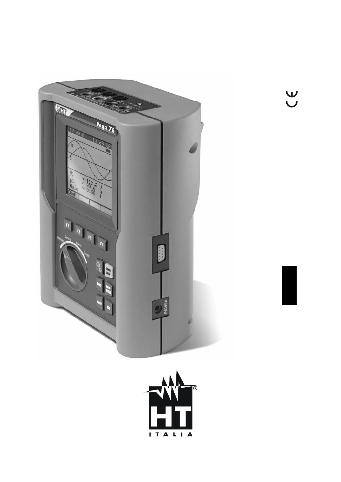
VEGA 76
User’s Manual
© Copyright HT ITALIA 2004 Release EN 2.00 - 08/06/2004


VEGA 76
Contents:
1. PRECAUTIONS AND SAFETY MEASURES ..............................................................3
1.1. GENERAL .............................................................................................................3
1.2. PRELIMINARY INSTRUCTIONS ..........................................................................3
1.3. DURING USE........................................................................................................4
1.4. AFTER USE ..........................................................................................................4
2. GENERAL DESCRIPTION...........................................................................................5
2.1. INTRODUCTION...................................................................................................5
2.2. FUNCTIONS..........................................................................................................5
2.3. INITIAL SCREEN ..................................................................................................5
3. PREPARING THE INSTRUMENT ................................................................................6
3.1. PRELIMINARY CHECK.........................................................................................6
3.2. POWER SUPPLY..................................................................................................6
3.3. CALIBRATION.......................................................................................................6
3.4. STORAGE.............................................................................................................6
4. HOW TO OPERATE.....................................................................................................7
4.1. INSTRUMENT - DESCRIPTION ...........................................................................7
4.2. KEYBOARD - DESCRIPTION...............................................................................7
4.3. DISPLAY - DESCRIPTION....................................................................................8
4.4. BACKLIGHT Function ...........................................................................................8
5. MENU GENERAL.........................................................................................................9
5.1. INITIAL SETTINGS ...............................................................................................9
5.1.1. How to adjust the contrast..............................................................................9
5.1.2. How to set date and time................................................................................9
5.1.3. How to set the language.................................................................................9
5.2. BASIC SETTING: ANALYZER CONFIG .............................................................10
5.2.1. How to set the type of electrical system under test ......................................10
5.2.2. How to set the fundamental frequency.........................................................10
5.2.3. How to set the current range........................................................................10
5.2.4. How to set the type of clamp........................................................................ 11
5.2.5. How to set the value of the transformer voltage ratio (TV RATIO) ...............11
5.2.6. How to enable/disable the password............................................................11
5.3. BASIC SETTING: RECORDER CONFIG............................................................12
5.4. ANALYZER MEMORY ........................................................................................19
5.5. RESET ................................................................................................................20
6. SWITCH FUNCTIONS................................................................................................21
6.1. POSITION "VOLTAGE".......................................................................................21
6.1.1. Symbols........................................................................................................21
6.1.2. "METER" mode............................................................................................22
6.1.3. "HARM" mode..............................................................................................23
6.1.4. "WAVE" mode..............................................................................................24
6.2. POSITION "CURRENT" ......................................................................................25
6.2.1. Symbols........................................................................................................25
6.2.2. “METER" mode ............................................................................................26
6.2.3. “HARM" mode ..............................................................................................27
6.2.4. "WAVE" mode..............................................................................................28
6.3. POSITION "POWER"..........................................................................................29
6.3.1. Symbols........................................................................................................29
6.3.2. "METER" mode............................................................................................30
6.3.2.1. Peak energy demand ...............................................................................31
6.3.3. "WAVE" mode..............................................................................................32
EN - 1

VEGA 76
6.4. POSITION "ENERGY".........................................................................................33
6.4.1. Symbols........................................................................................................33
6.4.2. "METER" mode............................................................................................34
7. STARTING A RECORDING.......................................................................................35
8. DURING A RECORDING...........................................................................................37
9. STOPPING A RECORDING OR AN ENERGY MEASUREMENT.............................38
10. CONNECTING THE INSTRUMENT TO A PC..........................................................39
11. MEASURING PROCEDURES..................................................................................40
11.1. USING THE INSTRUMENT IN A SINGLE PHASE SYSTEM.............................40
11.2. USING THE INSTRUMENT IN A THREE PHASE 4 WIRE SYSTEM.................41
11.3. USING THE INSTRUMENT IN A THREE PHASE 3 WIRE SYSTEM.................42
12. MAINTENANCE........................................................................................................43
12.1. GENERAL...........................................................................................................43
12.2. BATTERY REPLACEMENT................................................................................ 43
12.3. CLEANING..........................................................................................................43
13. TECHNICAL SPECIFICATIONS...............................................................................44
13.1. FEATURES.........................................................................................................44
13.1.1. Voltage measurement (Autoranging)............................................................44
13.1.2. Detection of voltage anomalies: manual range selection..............................44
13.1.3. Current measurement (using external transducer) .......................................44
13.1.4. Power measurement (cosϕ: 0.5c – 0.5i).......................................................44
13.1.5. Cosϕ measurement......................................................................................44
13.1.6. Measurement of harmonics..........................................................................45
13.1.7. Frequency measurement.............................................................................. 45
13.1.8. Compliance...................................................................................................45
13.1.9. Temperature drift..........................................................................................45
13.1.10. Safety ........................................................................................................... 45
13.1.11. General Features..........................................................................................45
13.2. ENVIRONMENT .................................................................................................46
13.2.1. Environmental conditions..............................................................................46
13.2.2. EMC..............................................................................................................46
13.3. ACCESSORIES..................................................................................................46
13.3.1. Standard accessories...................................................................................46
13.3.2. Optional accessories ....................................................................................46
14. APPENDIX 1 – MESSAGES DISPLAYED ...............................................................47
15. APPENDIX 2 – RECORDABLE PARAMETERS: SYMBOLS..................................48
16. APPENDIX 3 – THEORETICAL OUTLINES.............................................................49
16.1. VOLTAGE ANOMALIES (VOLTAGE SAG AND SURGE)..................................49
16.2. VOLTAGE AND CURRENT HARMONICS.........................................................49
16.2.1. Theory ..........................................................................................................49
16.2.2. Limit values for harmonics............................................................................50
16.2.3. Presence of harmonics: causes....................................................................51
16.2.4. Presence of harmonics: consequences........................................................51
16.3. POWER AND POWER FACTOR: DEFINITIONS...............................................52
16.3.1. Conventions on powers and power factors...................................................53
16.3.2. 3 Phase 3 Wire System................................................................................54
16.4. MEASURING METHOD: OUTLINES..................................................................55
16.4.1. Integration periods........................................................................................55
16.4.2. Power factor calculations..............................................................................55
17. AFTER-SALE SERVICE...........................................................................................56
17.1. WARRANTY .......................................................................................................56
17.2. SERVICE............................................................................................................56
EN - 2
VEGA 76
1. PRECAUTIONS AND SAFETY MEASURES
1.1. GENERAL
This instrument has been designed in compliance with Standard EN 61010.
For your own safety and to avoid damaging the instrument follow the
procedures described in this instruction manual and read carefully all notes
preceded by this symbol .
When taking measurements:
• avoid doing that in humid or wet places - make sur e that humidity is within the limits
indicated in section “environmental conditions”.
• avoid doing that in rooms where explosive gas, combustible gas, steam or excessive
dust is present.
• keep you insulated from the object under test.
• do not touch exposed metal parts such as test lead ends, sockets, fixing objects,
circuits etc.
• avoid doing that if you notice anomalous conditions such as breakages, deformations,
fractures, leakages of battery liquid, blind display etc.
The following symbols are used:
CAUTION - refer to the instruction manual - an improper use may damage the
instrument or its components
CAUTION
HIGH VOLTAGE: risk of electrical shocks
1.2. PRELIMINARY INSTRUCTIONS
• This instrument has been designed for use in environments of pollution degree 2.
• It can be used for voltage and current measurements on installations of overvoltage
category III 600V~ phase to phase / 300V~ phase to earth or CATII 350V phase to
earth up to (and no more than) 2000 meters altitude.
• You are recommended to respect the usual safety regulations aimed at protecting you
against dangerous currents and protecting the instrument against improper use.
• Only the original accessories supplied along with the instrument guarantee compliance
with the safety Standards in force. They must be in a good conditions and, if necessary,
replaced with identical ones.
• Do not test nor connect to any circuit exceeding the specified overload protection.
• Do not take measurements under environmental conditions exceeding the limits
indicated in this manual.
• Before connecting cables, test probes, crocodiles and clamps to the installation to be
tested make sure that the rotary selector is positioned on the right function.
EN - 3

VEGA 76
1.3. DURING USE
CAUTION
An improper use may damage the instrument and/or its components or
injure the operator.
• When the instrument is connected to the circuit under test do not touch any unused
terminal.
• When measuring current, other currents located near the leads may affect the
measuring accuracy.
• When measuring current, always position the wire in the very middle of the jaws in
order to obtain the highest accuracy.
• A measured value remains constant if the "HOLD" function is active. Should you notice
that the measured value remains unchanged, disable the “HOLD” function.
1.4. AFTER USE
• After use, turn off the instrument by pressing ON/OFF for a few seconds.
• If you expect not to use the instrument for a long time please keep to the storage
instructions described at paragraph 3.4.
EN - 4
VEGA 76
2. GENERAL DESCRIPTION
2.1. INTRODUCTION
VEGA 76 represents a new approach to the world of electrical measurements. Computer
assisted instruments like this permit an easy and fast analysis of a huge quantity of data.
2.2. FUNCTIONS
The instrument can:
• display in real time the electrical parameters of single phase and three-phase
systems (with and without neutral wire)
• perform a harmonic analysis of voltages and currents
• perform a direct energy measurement (without storing data).
• memorize (by pressing SAVE) the sampled values of the parameters present at the
instrument’s input by generating a "Smp" record inside the memory. It’s possible to
analyze memorized data ONLY by transferring them to a PC.
• record simultaneously (by pressing START after a proper setting): RMS values of
voltages, currents, corresponding harmonics, active, reactive and apparent powers,
power factors and cosϕ, active, reactive and apparent energies, voltage anomalies
(voltage sags and surges) with 10ms resolution. It’s possible to analyze recorded
data ONLY by transferring them to a PC.
Please note the difference between memorize and record. These terms
will be used repeatedly in this manual. Please focus on their definitions and
distinctions.
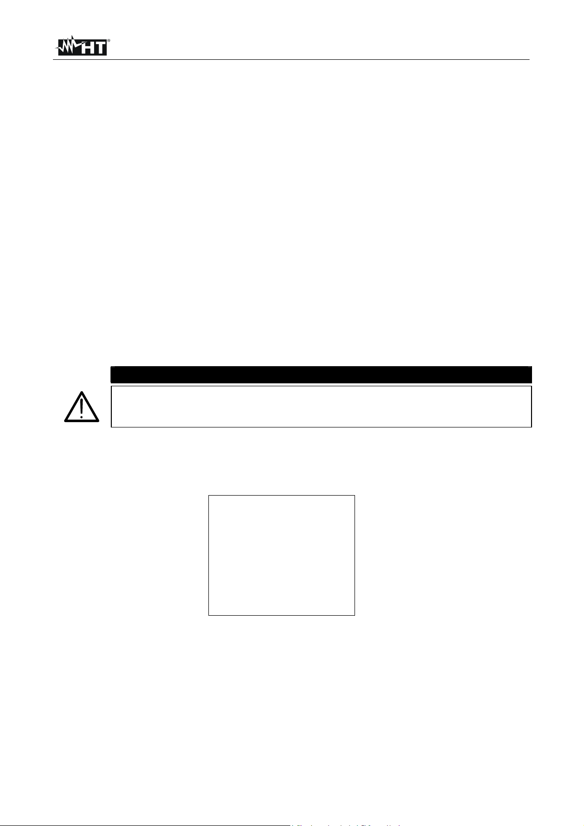
2.3. INITIAL SCREEN
When turning on the instrument by pressing ON/OFF, this screen will appear for a few
seconds:
CAUTION
Vega 76
HT ITALIA
SN: 00000000
CALIBRATION DATE
BAUD RATE 57600
Here you can see:
• serial number of the instrument (SN.:)
• firmware software release (VER.:)
• calibration date (CALIBRATION:)
• transmission speed through serial I/O (Baud Rate)
VER:x.xx
00.00.00
EN - 5
VEGA 76
3. PREPARING THE INSTRUMENT
3.1. PRELIMINARY CHECK
This instrument was checked both mechanically and electrically prior to shipment. All
possible cares and precautions were taken to let you receive the instrument in perfect
conditions. Notwithstanding we suggest you to check it rapidly (eventual damages may
have occurred during transport – if so please contact the local distributor from whom you
bought the item).
Make sure that all standard accessories mentioned in paragraph 13.3 are included.
Should you have to return back the instrument for any reason please follow the
instructions mentioned in paragraph 17.
3.2. POWER SUPPLY
The instrument can be powered by batteries (refer to paragraph 13.1.11 for details on
model, no. and battery life) and by an external power supply (refer to paragraph 13.3.1 for
details on the model) supplied with the instrument as a standard accessory. When
batteries are low, a low battery indication is displayed.
To replace/insert batteries follow the instructions indicated in paragraph 12.2.
For recordings use ALWAYS the external power supply (although the
instrument allows the operator to perform a recording using internal
batteries).
The instrument applies sophisticated algorithms to prolong the battery life. Particularly:
• it automatically switches off the backlight after 5 seconds.
• If the instrument is displaying in real time (and the external power supply is not
connected), after about 5 minutes from the last pressure on keys or selector rotation
the instrument automatically turns off ("AUTOPOWER OFF" procedure).
• If the instrument is recording or is measuring energy (and the external power supply is
not connected), after about 5 minutes from the last pressure on keys or selector
rotation the instrument starts a special procedure to save batteries ("ECONOMY
MODE"): the instrument keeps recording but the display is turned off.
3.3. CALIBRATION
The instrument complies with the technical specifications contained in this manual and
such compliance is guaranteed for 1 year. Annual recalibration is recommended.
3.4. STORAGE
After a period of storage in extreme environmental conditions exceeding the limits
mentioned in paragraph 13.2 let the instrument resume normal measuring conditions
before using it.
CAUTION
EN - 6
VEGA 76
4. HOW TO OPERATE
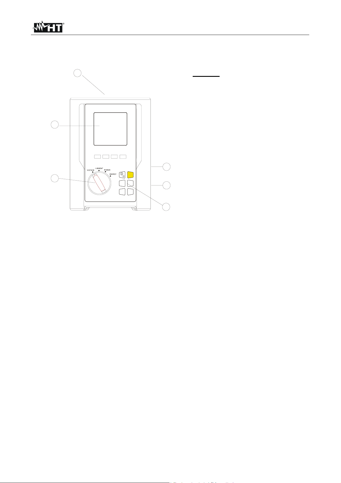
4.1. INSTRUMENT - DESCRIPTION
1
4
F1 F2 F3 F4
Legend:
1. Inputs for voltage and current
2. RS232 serial output
3. Plug for external power supply
4. Display
5. Selector switch
6. Keyboard
START
5
STOP
HOLD
SAVE
ENTER
ESC
ESC
MENU
3
6
4.2. KEYBOARD - DESCRIPTION
The following keys are available.
ON/OFF: turning on – turning off / Backlight ON (automatic switching off after
5 sec.)
F1, F2, F3, F4: multifunction keys. The various functions are deducible from the
symbols shown on the bottom of the display.
MENU: by pressing MENU it’s possible to check and modify the
recording parameters.
ESC: to leave a menu or a sub-menu.
ENTER/HOLD: double function key:
ENTER: to confirm the settings made
HOLD: to block the value updating in real time on all
screens. This function is disabled when recording
or measuring energy. When this function is active
it’s not possible to record or take energy
measurements.
2
SAVE: to save a record of “Smp” type (see paragraph
5.4) containing
the instantaneous values of voltage and current present on the
instrument inputs. This function is disabled during a recording.
START/STOP: to start/stop manually a recording (see chapter 7).
EN - 7
VEGA 76
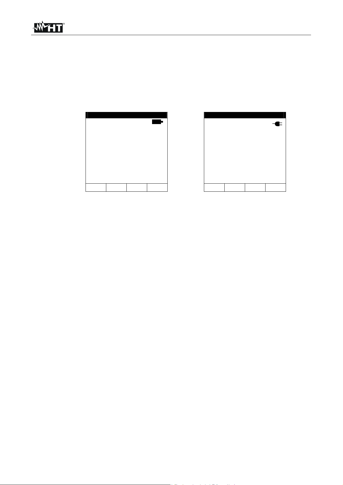
4.3. DISPLAY - DESCRIPTION
The display is a graphic module with a resolution of128 x 128 pixels (16384 pixels overall).
Each pixel has a dimension of 0.5mm x 0.5mm, the visible area is a square of 73mm x
73mm.
The first line of the display shows date and time. If not correct, you can set the exact ones
according to the procedure described at paragraph 5.1.2.
On the top right corner of the display you can always see a battery indicator and, if the
external power supply is connected, the corresponding symbol.
27.09.00 17:35:12 27.09.00 17:35:12
V1 = 230.2 V
V2 = 230.5 V
V3 = 230.6 V
V12 = 384.2 V
V23 = 385.4 V
V31 = 383.7 V
freq = 50.0 Hz
Phseq = 123
VOLTAGE
HARM WAVE
V1 = 230.2 V
V2 = 230.5 V
V3 = 230.6 V
V12 = 384.2 V
V23 = 385.4 V
V31 = 383.7 V
freq = 50.0 Hz
Phseq = 123
HARM WAVE
VOLTAGE
These symbols will be omitted in the following illustrations.
4.4. BACKLIGHT FUNCTION
When the instrument is turned on, press ON briefly to activate the backlight. The backlight
automatically turns off after 5 seconds. If batteries are too low the instrument automatically
disables the backlight function. A repeated use of the backlight function affects the battery
life.
EN - 8
VEGA 76
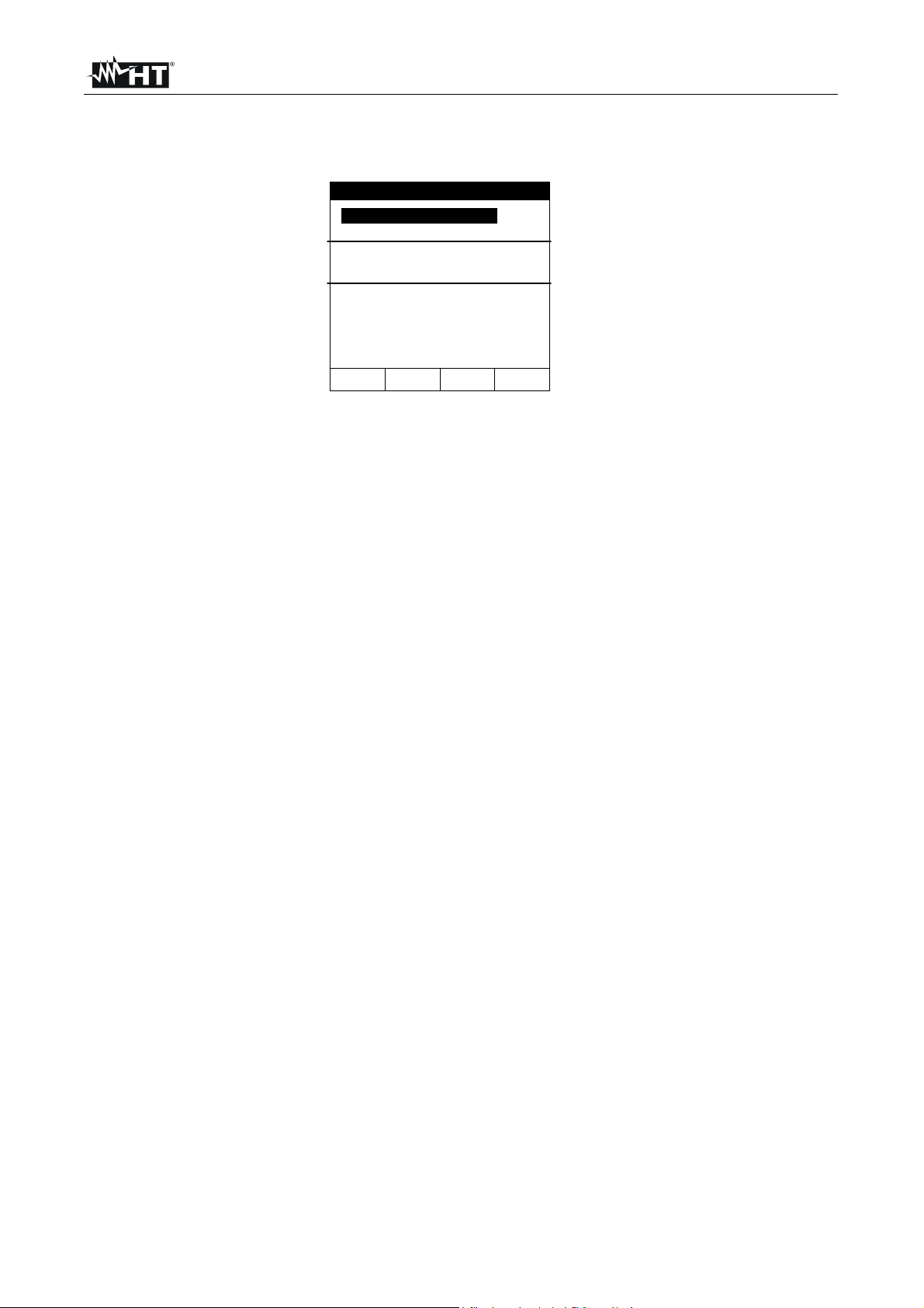
5. MENU GENERAL
By pressing MENU the following screen will be displayed:
MENU GENERAL
ANALYZER MEMORY
RESET
ANALYZER CONFIG
RECORDER CONFIG
CONTRAST
DATE&TIME
LANGUAGE
↓ ↑
It’s not possible to enter the MENU during a recording or a Real Time Energy
measurement.
5.1. INITIAL SETTINGS
5.1.1. How to adjust the contrast
By pressing the multifunction keys F1 and F2 position the cursor on CONTRAST and
confirm it by pressing ENTER.
By pressing the multifunction keys F3 and F4, adjust the contrast (higher values
correspond to a higher contrast, lower values correspond to a lower contrast). Press
ENTER to SAVE the change or press ESC to quit the modification.
This setting will remain unchanged also after turning off the instrument.
5.1.2. How to set date and time
By pressing the multifunction keys F1 and F2 position the cursor on DATE&TIME and
confirm by pressing ENTER.
By pressing the multifunction keys F1 and F2 position the cursor on the Date format
(FORMAT) and by pressing the F3 or F4 keys select one of the following Date formats:
DD.MM.YY (2 digits for day, 2 digits for Month, 2 digits for Year)
or
MM.DD.YY (2 digits for Month, 2 digits for Day, 2 digits for Year)
By pressing the multifunction keys F1 and F2 position the cursor on the value to be
modified and change the value by pressing F3 and F4.
The time is expressed as hh:mm (2 digits for hours, 2 digits for minutes) on a 24-hours
basis.
Press ENTER to SAVE the change or press ESC to quit the modification.
This setting will remain unchanged also after turning off the instrument.
5.1.3. How to set the language By pressing the multifunction keys F1 and F2 position the cursor on LANGUAGE (EN) or LINGUA (IT) and confirm by pressing ENTER.
By pressing the multifunction keys F1 and F2 position the cursor on the desired language
and press ENTER to SAVE the change or ESC to quit the modification.
This setting will remain unchanged also after turning off the instrument.
EN - 9
VEGA 76
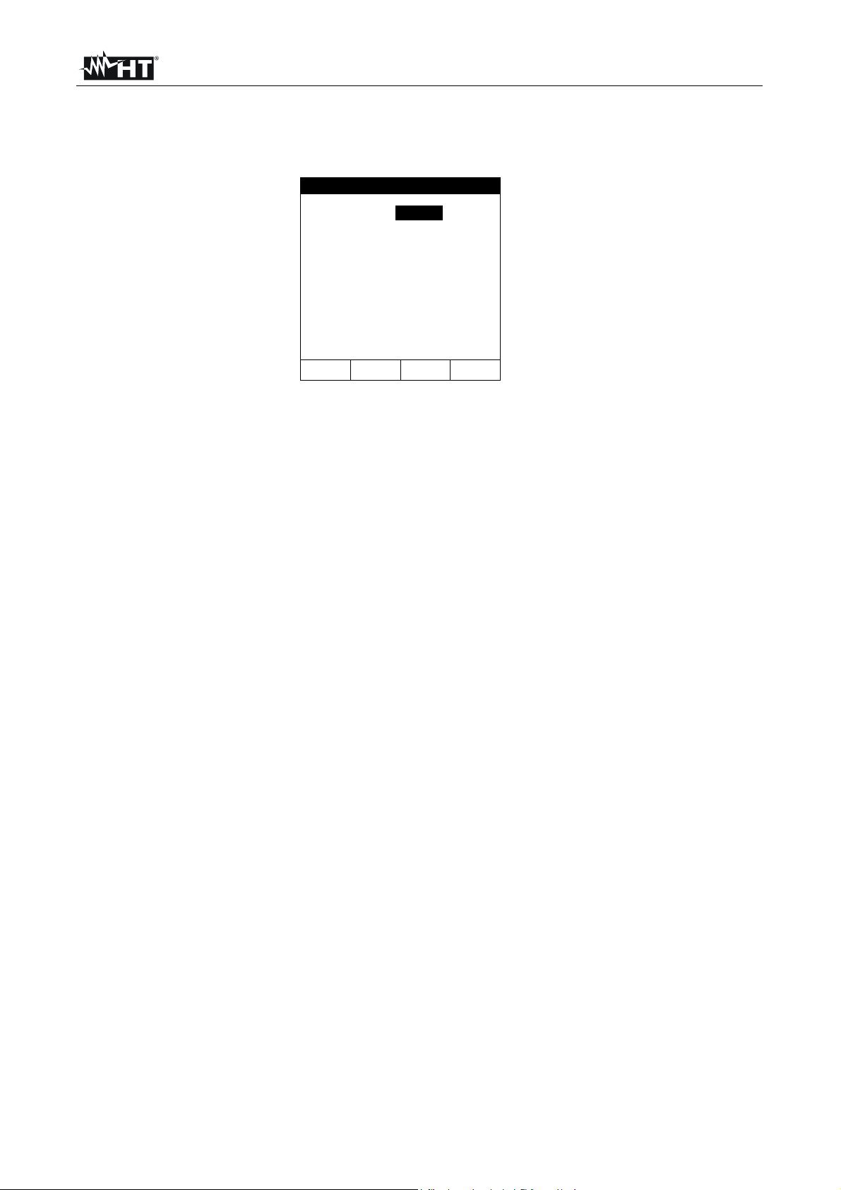
5.2. BASIC SETTING: ANALYZER CONFIG
By selecting ANALYZER CONFIG and pressing ENTER, the following screen will be
displayed:
ANALYZER CONFIG
SYSTEM :3PH4W
FREQUENCY:50HZ
CURRENT RANGE:1000A
CLAMP TYPE: STD
TV RATIO:0001
PASSWORD:ON
↓ ↑
+
-
This page of settings can be confirmed by pressing ENTER or cancelled by pressing ESC.
5.2.1. How to set the type of electrical system under test
This parameter permits to select the type of electrical system under test among the
following configurations:
• SINGLE: single-phase system
• 3PH3W: 3-wire system (three-phase system without neutral) (see paragraph 16.3.2)
• 3PH4W: 4-wire system (three-phase system with neutral)
The connections to the instrument inputs will have to be in accordance with the type of
system selected.
Position the cursor on the corresponding word by pressing the multifunction keys F1 and
F2 and set the desired value by pressing the multifunction keys F3 and F4.
5.2.2. How to set the fundamental frequency Position the cursor on the corresponding word by pressing the multifunction keys F1 and F2 and select the network frequency between the possible values 50Hz and 60Hz by
pressing the multifunction keys F3 and F4. This parameter is important ONLY if the input
voltage is not sufficient to recognize the frequency value (for example, only current clamps
are connected). In this case the instrument generates an internal synchronism equal to the
value of the set frequency.
5.2.3. How to set the current range The value of this parameter must be always equal to the full scale of the current clamps used to take the measurement. In case multi-scale clamps are used, the value of
this parameter must be equal to the scale selected on the clamps.
Set the desired value by pressing the multifunction keys F3 and F4.
EN - 10

VEGA 76
5.2.4. How to set the type of clamp
The value of this parameter must be always equal to the type of clamp being used.
Three types of clamps are available:
• STD: standard clamps or current transformers
• FlexINT: flexible clamps without integrator
• FlexEXT: flexible clamps with integrator
Set the desired value by pressing the multifunction keys F3 and F4.
CAUTION
If FlexINT is chosen, the current range can be set only at 1000A or 3000A.
5.2.5. How to set the value of the transformer voltage ratio (TV RATIO)
The instrument can be also interfaced with step-down transformers of the equipment under
test: it can display the value of the voltages present on the primary winding of these
transformers. To do this it will be necessary to set the value of the transformers’ windings
ratio from 2:1 to 3000:1. The default is set at 1:1 for measurements of none transformer
systems.
Select “TV RATIO” in the ANALYZER CONFIG menu. Set the desired value by pressing
the multifunction keys F3 and F4.
5.2.6. How to enable/disable the password
The instrument is provided with a protective routine to avoid the risk of being disturbed or
interrupted during a recording or an energy measurement. Once a recording or a direct
energy measurement has been started (with the option “PASSWORD” enabled), after
about 3 minutes from the last pressure on keys or selector rotation it won’t be possible to
press START/STOP to stop the recording, “PASSWORD” will be displayed and it will be
necessary to insert the password.
In order to insert the password (which is not changeable), press the multifunction keys in
the following sequence (within 10 seconds):
F1, F4, F3, F2
If you wait more than 10 seconds the display will return to the meter mode and the
instrument will continue recording. If you insert a wrong password the message “Password
error” will be displayed under “PASSWORD”. After a few seconds the display will return to
meter mode and the instrument will continue recording. In order to enable/disable this
option the correct password must be entered. The display will return to meter mode and
START/STOP will have to be pressed again to stop the recording. You will then need to
re-enter the “ANALYZER CONFIG” menu and scroll up or down to the item “PASSWORD:
ON” by pressing the multifunction keys F1 and F2. Then turn off the password by pressing
the multifunction keys F3 and F4.
EN - 11

VEGA 76
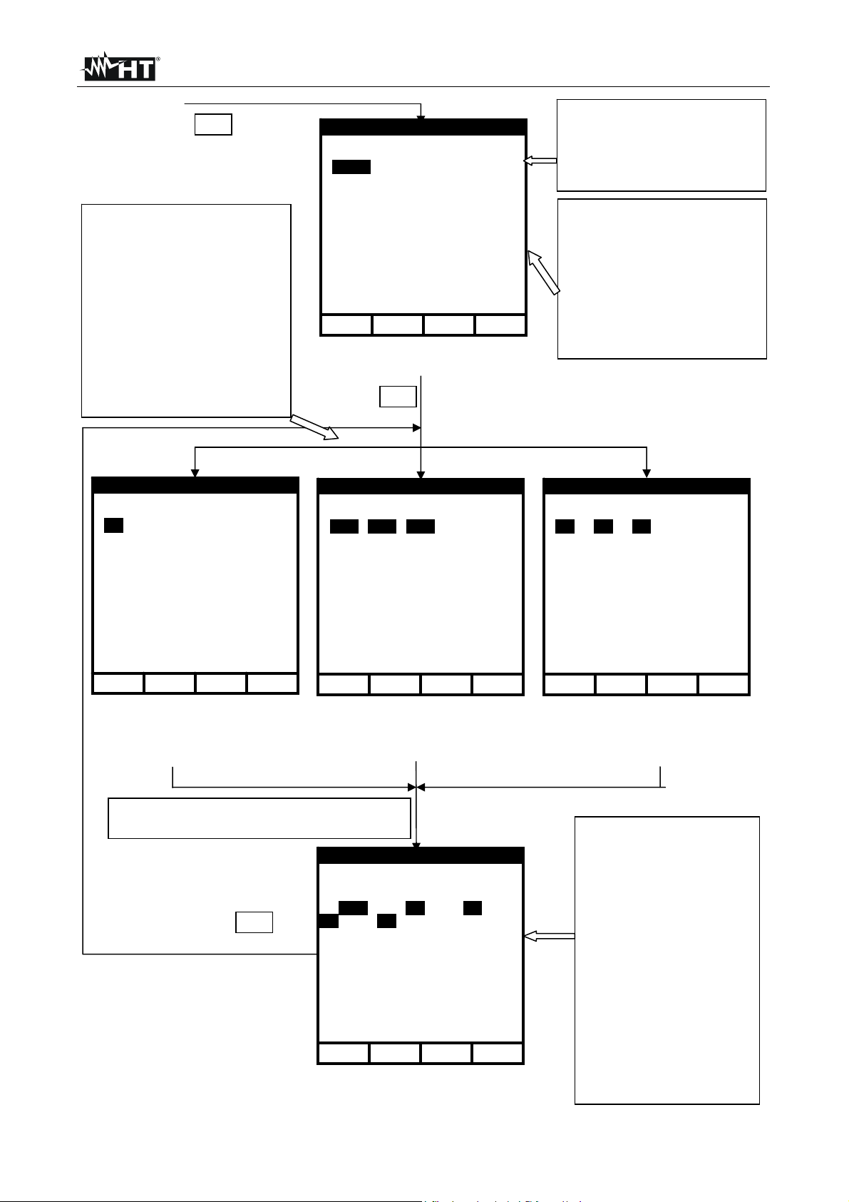
5.3. BASIC SETTING: RECORDER CONFIG
This option permits to check and eventually modify the recording parameters and the
selected parameters (up to a maximum of 64). The calculation of the selected values is not
affected by the selector’s position. If the number of selected values exceeds 64 the
message "too many param" will be displayed. The MENU mode is divided into 4 separate
sub-pages:
1st page: This page permits to set the START/ STOP mode (AUTO or MANUAL),
the START and STOP time if AUTO mode is selected, the Integration
Period value, the Enabling/Disabling of Voltage Anomalies detection, the
Enabling/Disabling of Harmonics detection. Press ENTER to confirm the
settings and pass to the following page.
Press ESC to leave the Menu without modifying the existing parameters.
2nd page: This page is dedicated to the settings related to the VOLTAGE recording.
Press ENTER to confirm the settings and pass to the following page.
Press ESC to leave this page without modifying the existing parameters.
From this page you can enter the sub-page “Harmonics” which permits to
select the voltage harmonics to be recorded.
Press ENTER to confirm the settings and leave the “Menu Harmonics".
Press ESC to leave the "Menu Harmonics" without modifying the existing
parameters.
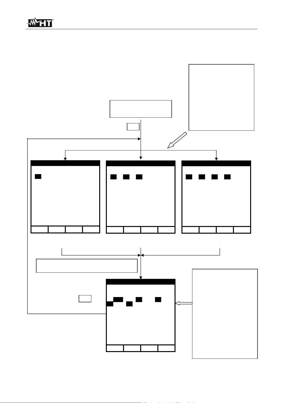
3rd page: This page is dedicated to the settings related to the CURRENT
recording.
Press ENTER to confirm the settings and pass to the following page.
Press ESC to leave this page without modifying the existing parameters.
From this page you can enter the sub-page “Harmonics” which permits to
select the current harmonics to be recorded.
Press ENTER to confirm the settings and leave the “Menu Harmonics".
Press ESC to leave the "Menu Harmonics" without modifying the existing
parameters.
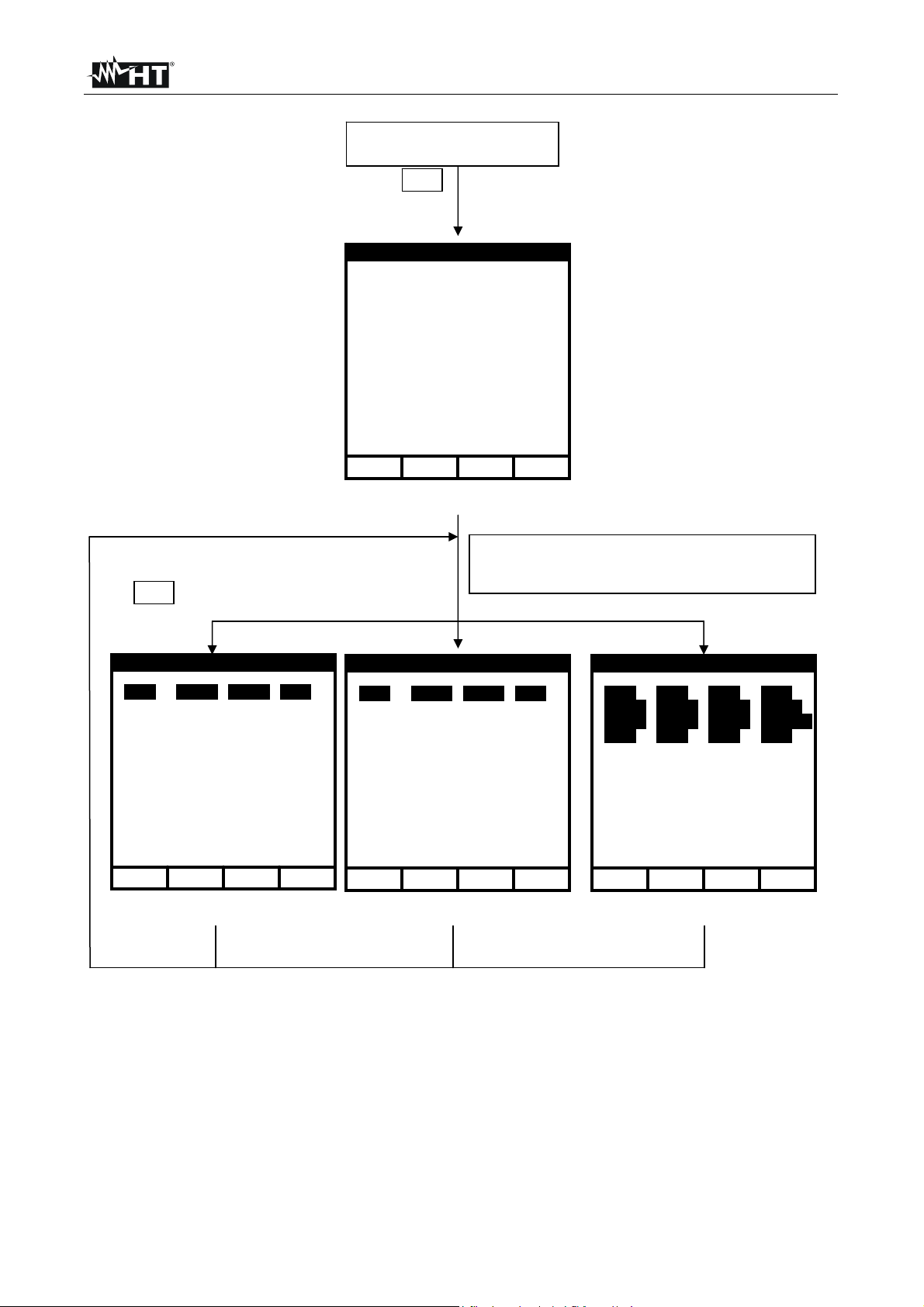
4th page: Menu composed of two sub-pages dedicated to the selection of the
POWERS and ENERGIES to be recorded. From this page you can enter
the sub-page “POWER” and “ENERGY” which permits to select the
parameters to be recorded.
By selecting the active powers for the recording, the corresponding active
energies will be automatically selected.
By selecting the reactive powers for the recording, the corresponding reactive
energies will be selected.
Press ENTER to confirm the settings.
Press ESC to leave the "Menu" without modifying the existing parameters.
The various pages of the "RECORDER CONFIG" can be schemed as follows:
EN - 12
VEGA 76
↑
↑
↑
MENU
Use the multifunction keys F1, F2
to position the cursor on the
desired word and use the
multifunction keys F3 / F4 to select
/ deselect the desired parameter
(it’s selected if marked in black).
Press ENTER to confirm and leave
the Menu keeping the settings
made.
Press ESC to leave the Menu
without modifying the existing
parameters.
RECORDER CONFIG
START
MANU
STOP
MANU
INT. PERIOD: 15min
HARM REC: ON
ANOM REC: ON
↓
st
1
Page of the RECORDER
CONFIG MENU
ENTER
+ -
To Select MANUAL or AUTOMATIC
start/stop mode, place the cursor on
MANU or AUTO using the
multifunction key F1 or F2 and select
the desired mode using F3 or F4.
Use the multifunction keys F1, F2 to
position the cursor on the desired
word and use the multifunction keys
F3 / F4 to modify the value.
Press ENTER to confirm and proceed
inside the Menu the Menu keeping
the settings made.
Press ESC to leave the Menu without
modifying the existing parameters.
RECORDER CONFIG
VOLTAGE:
V1
HARM. REC:Pg (ON)
Vref P-N: 230V
LIM+: 06% (243.8V)
LIM-: 10% (207.0V)
RECORDER CONFIG
VOLTAGE REC:
V12 V32 V31
HARM. REC:Pg (ON)
Vref P-P: 400V
LIM+: 06% (424.0V)
LIM-: 10% (360.0V)
RECORDER CONFIG
VOLTAGE REC:
V1 V2 V3
V12 V32 V31
HARM. REC:Pg (ON)
Vref P-N: 230V
LIM+: 06% (243.8V)
LIM-: 10% (207.0V)
↓ ↑
Example of 2
phase mode with ANOM flag
enabled
+ -
nd
page in single-
wire” three-phase mode with
If you want to change Voltage Harm. Selection place the
cursor on the corresponding “Pg” symbol then Press F3
VOLTAGE HARMONICS
ENTER
Thd DC 01 02 03 04
05 06 07 08 09 10 11
12 13 14 15 16 17 18
19 20 21 22 23 24 25
26 27 28 29 30 31 32
33 34 35 36 37 38 39
40 41 42 43 44 45 46
47 48 49
↓
Example of 2
↓
Example of sub-page
"VOLTAGE HARMONICS"
ANOM flag enabled
RECORDER CONFIG
nd
page in “3-
+ -
+ -
↓ ↑
Example of 2
three-phase mode with ANOM
flag enabled
Use the multifunction keys F1,
F2 to position the cursor on the
desired voltage harmonic and
use the multifunction keys F3 /
F4 to select / deselect (it’s
selected if highlighted in
black).
Press ENTER to confirm.
Press ESC to leave the Menu
without modifying the existing
settings.
The instrument will record the
values of the selected
harmonics corresponding to
the voltages selected in one of
the two pages of the Menu
previously illustrated.
+ -
nd
page in “4-wire”
EN - 13
VEGA 76
↑
↑
of RECORDER CONFIG MENU
From 2nd page
ENTER
Use the multifunction keys F1,
F2 to position the cursor on the
desired word and use the
multifunction keys F3 / F4 to
modify the value or select /
deselect the desired parameter
(it’s selected if marked in black).
Press ENTER to confirm.
Press ESC to leave the Menu
without modifying the existing
settings.
RECORDER CONFIG
CURRENT REC:
I1
HARM. REC:Pg (ON)
RECORDER CONFIG
CURRENT REC:
I1 I2 I3
HARM. REC: Pg (ON)
RECORDER CONFIG
CURRENT REC:
I1 I2 I3 IN
HARM. REC:Pg (ON)
↓ ↑
Example of 3
phase mode
+ -
rd
page in single-
↓
Example of 3rd page in “3-wire”
If you want to change Current Harm. Selection place
Cursor on the corresponding “Pg” symbol then Press F3
CURRENT HARMONICS
ENTER
Thd DC 01 02 03 04
05 06 07 08 09 10 11
12 13 14 15 16 17 18
19 20 21 22 23 24 25
26 27 28 29 30 31 32
33 34 35 36 37 38 39
40 41 42 43 44 45 46
47 48 49
↓
"CURRENT HARMONICS"
three-phase mode
RECORDER CONFIG
Example of sub-page
+ -
+ -
↓ ↑
Example of 3rd page in “4-wire”
three-phase mode
Use the multifunction keys F1,
F2 to position the cursor on the
desired current harmonic and
use the multifunction keys F3 /
F4 to select / deselect (it’s
selected if marked in black).
Press ENTER to confirm.
Press ESC to leave the Menu
without modifying the existing
settings.
The instrument will record the
values of the selected harmonics
corresponding to the currents
selected in one of the two pages
of the Menu previously
illustrated.
+ -
EN - 14

VEGA 76
↑
↑
of RECORDER CONFIG MENU
From 3rd page
ENTER
RECORDER CONFIG
CO-GENERATION:ON
POWER:Pg
ENERGY:Pg
↓
Example of 4th page
+ -
ENTER
In order to select the POWER to be recorded use the
multifunction keys F1, F2 to position the cursor on the
corresponding “Pg” Symbol and then press F3
RECORDER CONFIG
P1 Q1i Q1c S1
Pf1 dPf1
↓ ↑
Example of POWER sub-page in
single-phase mode
+ -
RECORDER CONFIG
Pt P12 P32
Qti Q12i Q32i
Qtc Q12c Q32c
St S12 S32
Pft dPft
↓
Example of POWER sub-page
in “3-wire” three-phase mode
+ -
RECORDER CONFIG
Pt P1 P2 P3
Qti Q1i Q2i Q3i
Qtc Q1c Q2c Q3c
St S1 S2 S3
Pfi Pf1 Pf2 Pf3
dPfi dPf1 dPf2 dPf3
↓ ↑
Example of POWER sub-page in
“4-wire” three-phase mode
+ -
By selecting the active powers for the recording, the corresponding active energies will be
automatically selected.
By selecting the reactive powers for the recording, the corresponding reactive energies will be
automatically selected.
EN - 15
VEGA 76
↑
↑
y
of RECORDER CONFIG MENU
From 3rd page
ENTER
RECORDER CONFIG
CO-GENERATION:ON
POWER:Pg
ENERGY:Pg
↓
Example of 4th page
+ -
ENTER
In order to select the ENERGIES to be recorded use the
multifunction ke
corresponding “Pg” Symbol and then press F3
s F1, F2 to position the cursor on the
RECORDER CONFIG
Ea1 Eri1 Erc1 Es1
↓ ↑
Example of ENERGY sub-page
in single-phase mode
+ -
RECORDER CONFIG
Eat Erit Erct Est
↓
Example of ENERGY sub-page
in “3-wire” three-phase mode
+ -
RECORDER CONFIG
Eat Ea1 Ea2 Ea3
Erit Eri1 Eri2 Eri3
Erct Erc1 Erc2 Earc3
Est Es1 Es2 Es3
↓ ↑
Example of ENERGY sub-page
in “4-wire” three-phase mode
+ -
By selecting/deselecting the active energies for the recording, the corresponding active powers
will be automatically selected/deselected.
By selecting/deselecting the reactive energies for the recording, the corresponding reactive
powers will be selected/deselected
By selecting/deselecting the reactive energies for the recording, the corresponding reactive
powers will be selected/deselected.
EN - 16
 Loading...