

HT Italia PQA819, PQA820 User Manual

Copyright HT ITALIA 2014 Version EN 2.01 - 26/05/2014
PQA819 – PQA820
User manual

PQA819 - PQA820
EN – 1
Table of contents
1. PRECAUTIONS AND SAFETY MEASURES ........................................................... 3
1.1. Preliminary instructions .................................................................................................... 3
1.2. During use ........................................................................................................................ 4
1.3. After use ........................................................................................................................... 4
1.4. Definition of measurement (overvoltage) category .......................................................... 4
2. GENERAL DESCRIPTION ....................................................................................... 5
2.1. Foreword .......................................................................................................................... 5
2.2. Instrument functions ......................................................................................................... 5
3. PREPARATION FOR USE ....................................................................................... 6
3.1. Initial checks ..................................................................................................................... 6
3.2. Instrument power supply .................................................................................................. 6
3.3. Calibration ........................................................................................................................ 6
3.4. Storage ............................................................................................................................. 6
4. NOMENCLATURE .................................................................................................... 7
4.1. Instrument description ...................................................................................................... 7
4.2. Keyboard description ....................................................................................................... 7
4.3. Description of the LED ..................................................................................................... 7
5. INITIAL SETTINGS ................................................................................................... 8
5.1. Setting the electrical system ............................................................................................ 8
5.2. Setting type of clamp ...................................................................................................... 11
5.3. Setting the clamp's full scale .......................................................................................... 11
5.4. Setting the value of transformation ratio of VTs ............................................................. 11
5.5. Setting limits for voltage anomalies ............................................................................... 11
5.6. Setting the integration period ......................................................................................... 11
5.7. Setting a programmed start and stop ............................................................................. 12
5.8. Setting the instrument's date and time ........................................................................... 12
6. MEASURING PROCEDURES ................................................................................ 13
6.1. Connection in a single-phase system ............................................................................ 13
6.2. Connection in a three-phase 3-wire system ................................................................... 14
6.3. Connection in a three-phase 4-wire system ................................................................... 15
7. RECORDING OF ELECTRICAL PARAMETERS ................................................... 16
7.1. Starting recording ........................................................................................................... 16
7.2. While recording .............................................................................................................. 16
7.3. Stopping recording ......................................................................................................... 16
8. MEMORY MANAGEMENTS ................................................................................... 17
8.1. Clear data ....................................................................................................................... 17
9. TRANSFERRING DATA TO THE MANAGEMENT SOFTWARE .......................... 18
9.1. Transferring data via USB port....................................................................................... 18
9.2. Transferring data via WiFi .............................................................................................. 18
9.3. Connection to iOS/Android devices through WiFi .......................................................... 18
10. MAINTENANCE ...................................................................................................... 19
10.1. General information ................................................................................................ 19
10.2. Cleaning the instrument .......................................................................................... 19
10.3. End of life ................................................................................................................ 19
11. TECHNICAL SPECIFICATIONS............................................................................. 20
11.1. Technical characteristics ........................................................................................ 20
11.2. Reference guidelines .............................................................................................. 21
11.3. General characteristics ........................................................................................... 21
11.4. Environment............................................................................................................ 21
11.4.1. Environmental conditions for use ............................................................................... 21
11.5. Accessories ............................................................................................................ 21
12. APPENDIX – THEORETICAL OUTLINE ................................................................ 22

PQA819 - PQA820
EN – 2
12.1. Voltage Anomalies .................................................................................................. 22
12.2. Voltage and current harmonics ............................................................................... 23
12.2.1. Limit values for harmonics ......................................................................................... 24
12.2.2. Causes of the presence of harmonics ........................................................................ 24
12.2.3. Consequence of the presence of harmonics .............................................................. 25
12.3. Definitions of power and power factor .................................................................... 26
12.3.1. Conventions on powers and power factors ................................................................ 27
12.4. Information on the measuring method .................................................................... 29
12.4.1. Integration period ....................................................................................................... 29
12.4.2. Calculation of the power factor ................................................................................... 29
13. SERVICE ................................................................................................................ 30
13.1. Warranty conditions ................................................................................................ 30
13.2. Service .................................................................................................................... 30
PQA819 - PQA820
EN – 3
1. PRECAUTIONS AND SAFETY MEASURES
The instrument has been designed in compliance with directive IEC/EN61010-1 relevant to
electronic measuring instruments. For your safety and in order to prevent damaging the
instrument, please carefully follow the procedures described in this manual and read all
notes preceded by the symbol with the utmost attention.
Before and after carrying out the measurements, carefully observe the following
instructions:
Do not carry out any voltage or current measurement in humid environments.
Do not carry out any measurements in case gas, explosive materials or flammables are
present, or in dusty environments.
Avoid any contact with the circuit being measured if no measurements are being
carried out.
Avoid any contact with exposed metal parts, with unused measuring probes, circuits,
etc.
Do not carry out any measurement in case you find anomalies in the instrument such
as deformation, breaks, substance leaks, absence of display on the screen, etc.
In this manual, and on the instrument, the following symbols are used:
Warning: observe the instructions given in this manual; improper use could
damage the instrument or its components.
High voltage danger: electrical shock hazard.
Double-insulated meter
AC voltage or current
The voltage values indicated to the left of this symbol are referred to the ground
1.1. PRELIMINARY INSTRUCTIONS
This instrument has been designed for use in environments of pollution degree 2.
It can be used for voltage and current measurements on installations with overvoltage
category CAT IV 300V AC to earth and maximum rated voltage between inputs 415V
AC
Please take the standard safety precautions aimed at protecting you against dangerous
electrical currents and protecting the instrument against incorrect use
Only the accessories provided together with the instrument will guarantee safety
standards. They must be in good conditions and be replaced with identical models,
when necessary.
Do not test circuits exceeding the specified current and voltage limits.
Before connecting cables, alligator clips and clamps to the circuit being measured,
check that the desired configuration has been set.

PQA819 - PQA820
EN – 4
1.2. DURING USE
Please carefully read the following recommendations and instructions:
CAUTION
Failure to comply with the caution notes and/or instructions may damage
the instrument and/or its components or be a source of danger for the
operator.
When the instrument is connected to the circuit under test, do not touch any unused
terminal.
During current measurement, any other current near the clamp may affect
measurement precision.
When measuring current, always put the conductor as near as possible to the middle of
the clamp jaw, to obtain the most accurate reading.
1.3. AFTER USE
When measures are completed, switch off the instrument by pressing ON/OFF key.
If the instrument is not to be used for a long time, please follow the instructions for
storage described in § 3.4
1.4. DEFINITION OF MEASUREMENT (OVERVOLTAGE) CATEGORY
Standard “IEC/EN61010-1: Safety requirements for electrical equipment for measurement,
control and laboratory use, Part 1: General requirements” defines what measurement
category, commonly called overvoltage category, is. § 6.7.4: Measured circuits, reads:
(OMISSIS)
Circuits are divided into the following measurement categories:
Measurement category IV is for measurements performed at the source of the low-
voltage installation.
Examples are electricity meters and measurements on primary overcurrent protection
devices and ripple control units.
Measurement category III is for measurements performed on installations inside
buildings.
Examples are measurements on distribution boards, circuit breakers, wiring, including
cables, bus-bars, junction boxes, switches, socket-outlets in the fixed installation, and
equipment for industrial use and some other equipment, for example, stationary motors
with permanent connection to fixed installation.
Measurement category II is for measurements performed on circuits directly
connected to the low-voltage installation.
Examples are measurements on household appliances, portable tools and similar
equipment.
Measurement category I is for measurements performed on circuits not directly
connected to MAINS.
Examples are measurements on circuits not derived from MAINS, and specially
protected (internal) MAINS-derived circuits. In the latter case, transient stresses are
variable; for that reason, the standard requires that the transient withstand capability of
the equipment is made known to the user
PQA819 - PQA820
EN – 5
2. GENERAL DESCRIPTION
2.1. FOREWORD
This manual refers to PQA819 and PQA820 models. In the whole manual, the word
“instrument” generically indicates PQA820 model, unless otherwise indicated. The
instrument allows for a totally new approach to electric measurements. Using computeraided instruments allows analyzing a huge amount of data with a simplicity and speed
impossible to obtain with any other system.
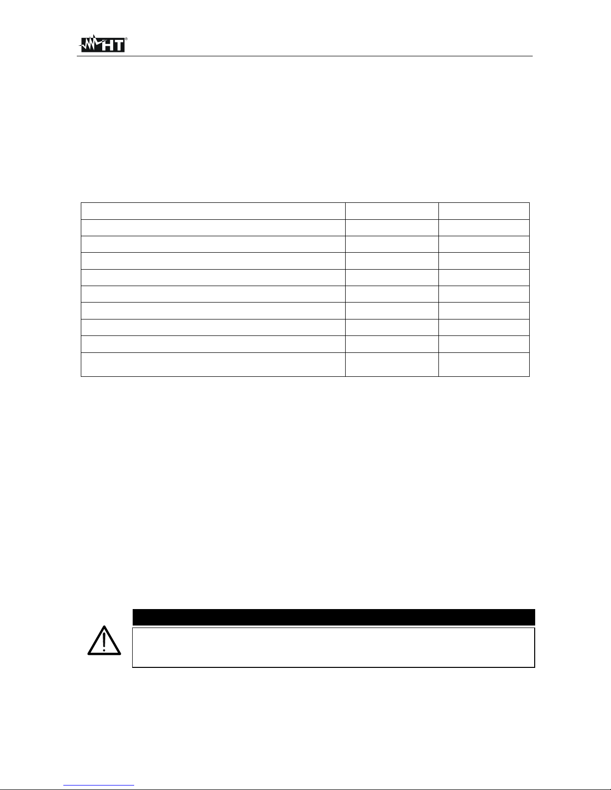
The differences between the models are listed in the following Table 1
Function description PQA819 PQA820
Recording of neutral current
Recording of voltage anomalies (sags, swells)
Recording of voltage unbalance
Recording of voltage/current harmonics up to 49th order
Recording of apparent power
Recording of generated power/energy
Recording of generated power factor / Cos
Number of selectable parameters 44 (fixed) 383 (fixed)
Recording autonomy (days)
> 230
(@ IP=15min)
> 30
(@ IP=10min)
Table 1: Differences between model PQA819 and PQA820
2.2. INSTRUMENT FUNCTIONS
The instrument allows performing the following functions:
A real-time display (with connection to PC and/or iOS/Android devices) of the values
of the electric quantities of a single-phase or three-phase system with or without neutral
and of the harmonic analysis of voltages and currents
Recording (through the appropriate setting) over time of the values of AC/DC voltages,
voltage unbalance (PQA820), voltage anomalies (sags, swells) with a resolution of
10ms (PQA820), AC/DC currents, neutral current (PQA820) of the values of the
relevant harmonics (PQA820), THD% value, of the values of active, reactive and
apparent powers (PQA820), of power factors and cos, of the values of active and
reactive energies, where recording is intended as saving in the instrument's memory
the values taken by the electrical quantities over time.
CAUTION
These terms will be used several times in this manual. We therefore invite
you to try and immediately focus the distinctions between the definitions
listed above.
PQA819 - PQA820
EN – 6
3. PREPARATION FOR USE
3.1. INITIAL CHECKS
Before shipping, the instrument has been checked from an electric as well as mechanical
point of view. All possible precautions have been taken so that the instrument is delivered
undamaged. However, we recommend generally checking the instrument in order to detect
possible damage suffered during transport. In case anomalies are found, immediately
contact the forwarding agent. We also recommend checking that the packaging contains
all components indicated in § 11.5. In case of discrepancy, please contact the Dealer. In
case the instrument should be replaced, please carefully follow the instructions given in §
13.
3.2. INSTRUMENT POWER SUPPLY
The instrument may be supplied in two ways:
External supply: red and yellow terminals (rated voltage field: 100 415V, 50/60Hz).
Internal supply: internal rechargeable batteries through red and yellow terminals.
CAUTION
When recording, we recommend ALWAYS using the external supply
If the external supply fails, the instrument automatically switches to the
internal supply provided by rechargeable batteries
3.3. CALIBRATION
The instrument has the technical specifications described in this manual. The instrument's
performance is guaranteed for one year starting from the date of purchase.
3.4. STORAGE
In order to guarantee precise measurement, after a long storage time under extreme
environmental conditions, wait for the instrument to come back to normal condition (see §
11.4.1).
PQA819 - PQA820
EN – 7
4. NOMENCLATURE
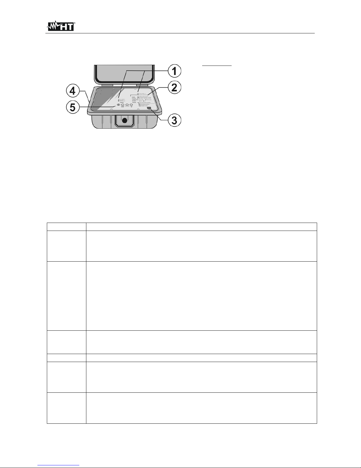
4.1. INSTRUMENT DESCRIPTION
CAPTION:
1. Indication LEDs
2. Description of the indication LEDs
3. USB port
4. Voltage and Current inputs
5. Keyboard
Fig. 1: Instrument description
4.2. KEYBOARD DESCRIPTION
The keyboard includes the following keys:
ON/OFF: pressing this key to switches the instrument on. Press the key approx. 2s to
switches the instrument off. If the instrument do not switch off press and hold this key
for at least 5s
START/STOP: for manually starting and stopping recording (see § 7 and 7.3).
SYSTEM: It allows for the selection of the electrical system (Single phase, Three phase 3-
wire and 4-wire)
WiFi/RF: it allows for the selection of the communication mode, WiFi or RF (only for the
communication with other HT instruments).
4.3. DESCRIPTION OF THE LED
LED Description
POWER
It describes the status and supply mode of the instrument:
Off: instrument switched off
Flashing green: instrument switched on supplied by internal batteries
Flashing red: internal batteries almost flat
STATUS
It described the instrument status:
Off: No recording in progress
Flashing green: Recording in progress
Green: Instrument waiting to start recording. Recording will always start at
the beginning of the minute after the START button has been pressed
/ receipt of the start recording control
Flashing red: Memory full
Red: Internal error – use the management software to identify the type of
malfunction. Some of them may also prevent recording.
RF/WiFi
It described what communication mode is currently set in the instrument:
Off: WiFi mode
Flashing green: RF mode (only for connection with other HT instruments)
CONNECTION It indicates if a WiFi or RF connection is active (according to the communication mode set)
SYSTEM
It indicates the electrical system currently set:
Off: Single-phase mode
Flashing green: Three-phase without neutral mode
Green: Three-phase with neutral mode
ERROR
It indicates possible connection errors:
Off: No error detected
Flashing red: Phase sequence incorrect
Red: One of the active powers measured by the instrument is negative.
Table 2: Description of LEDs
PQA819 - PQA820
EN – 8
5. INITIAL SETTINGS
CAUTION
The instrument may be configured only through the relevant management
software, except for the selection of the electrical system, which may also be
performed through the SYSTEM key in the instrument's keyboard
5.1. SETTING THE ELECTRICAL SYSTEM
This parameter allows selecting the type of electrical system to be analyzed. It is possible
to select the electrical system through the SYSTEM button in the instrument's keyboard.
Following configurations are available:
Single-phase system
Three-phase system without neutral (3-wires)
Three-phase system with neutral (4-wires)
Each electrical system is associated with a list of parameters automatically recorded by
the instrument (not modifiable).
SYMBOL DESCRIPTION
V1 RMS value of voltage of Phase 1 or DC
Freq. Mains frequency
I1 RMS value of Phase 1 current or DC
THDV1%, Harmonic distortion percentage factor of Phase 1 voltage
DCV1, Har1V1, ,Har49V1 Voltage harmonics of Phase 1 (PQA820)
THDI1% Harmonic distortion percentage factor of Phase 1 curre nt
DCI1, Har1I1, ,Har49I1 Current harmonics of Phase 1 (PQA820)
P1+ Absorbed active power Phase 1
Ea1+ Absorbed active energy Phase 1
Q1i+ Absorbed inductive reactive power Phase 1
Er1i+ Absorbed inductive reactive energy Phase 1
Q1c+ Absorbed capacitive reactive power Phase 1
Er1c+ Absorbed capacitive reactive energy Phase 1
S1+ Absorbed apparent power Phase 1 (PQA820)
Es1+ Absorbed appar ent energy Phase 1 (PQA820)
Pf1i+ Value of the absorbed inductive power factor of Phase 1
dPf1i+ +
Value of the absorbed inductive cos
of Phase 1
Pf1c+ Value of the absorbed capacitive power factor of Phase 1
dPf1c+
Value of the absorbed capacitive cos
of Phase 1
P1- Generated active power Phase 1 (PQA820)
Ea1- Generated active energy Phase 1 (PQA820)
Q1i- Generated inductive reactive power Phase 1 (PQA820)
Er1i- Generated inductive reactive en ergy Phase 1 (PQA82 0)
Q1c- Generated capacitive reactive power Phase 1 (PQA820)
Er1c- Generated capacitive reactive energy Phase 1 (PQA820)
S1- Generated apparent power Phase 1 (PQA820)
Es1- Generated apparent energy Phase 1 (PQA820)
Pf1i- Value of the generated inductive power factor of Phase 1 (PQA820)
dPf1i-
Value of the generated inductive cos
of Phase 1 (PQA820)
Pf1c- Value of the generated capacitive power factor of Phase 1 (PQA820)
dPf1c-
Value of the generated capacitive cos
of Phase 1 (PQA820)
Table 3: List of the parameters automatically recorded for a single-phase system
PQA819 - PQA820
EN – 9
SYMBOL DESCRIPTION
V1PE, V2PE, V3PE RMS value of voltage of Phase 1, Phase 2, Phase 3 with respect to PE
V12, V23, V31 RMS value of delta voltages
Freq. Mains frequency
I1, I2, I3 RMS value of current of Phase 1, Phase 2, Phase 3 neutr al
THDV1%, THDV2%, THDV3% Harmonic distortion percentage factor of voltage of Phase 1, Phase 2, Phase 3
DCVx, Har1Vx, ,Har49Vx (x=1,2,3) - Voltage harmonics of Phase 1, Phase 2, Phas e 3 (PQA820)
THDI1%, THDI2%, THDI3% Harmonic distortion percentage factor of current of Phase 1, Phase 2, P hase 3
DCIx, Har1Ix, ,Har49Ix (x=1,2,3) - Current harmonics of Phase 1, Phase 2, Phase 3 (PQA820)
u2, uo Unbalance of voltages - Percentage value of the negative sequence (PQA820)
uo Unbalance of voltages - Percentage value of the zero sequence (PQA820)
Pt+, P1+, P2+, P3+ Absorbed active power Total, Phase 1, Phase 2, Phase 3
Eat+, Ea1+, Ea2+, Ea3+ Absorbed active energy Total, Phase 1, Phase 2, Phase 3
Qti+, Q1i+, Q2i+, Q3i+ Absorbed inductive reactive power Total, Phase 1, Phase 2, Phase 3
Erti+, Er1i+, Er2i+, Er3i+ Absorbed inductive reactive energy Total, Phase 1, Phase 2, Phase 3
Qtc+, Q1c+, Q2c+, Q3c+ Absorbed capacitive reactive power Total, Phase 1, Phase 2, Phase 3
Ertc+, Er1c+, Er2c+, Er3c+ Absorbed capacitive reactive energy Total, Phase 1, Phase 2, Phase 3
St+, S1+, S2+, S3+ Absorbed apparent power Total, Phase 1, Phase 2, Phase 3 (PQA820)
Est+, Es1+, Es2+, Es3+ Absorbed apparent energy Total, Phase 1, Phase 2, Phase 3 (PQA820)
Pfti+, Pf1i+, Pf2i+, Pf3i+ Values of the absorbed inductive power factors Total, Phase 1, Phase 2, Phase 3
dPfti+, dPf1i+,d Pf2i+, dPf3i+
Values of the absorbed inductive cos
Total, Phase 1, Phase 2, Phase 3
Pftc+, Pf1c+, Pf2c+, Pf3c+ Values of the absorbed capacitive power factors Total, Ph ase 1, Phase 2, Phase 3
dPftc+, dPf1c+, dPf2c+, dPf3c+
Values of the absorbed capacitive cos
Total. Phase 1, Phase 2, Phase 3
Pt-, P1-, P2-, P3- Generated active power Total, Phase 1, Phase 2, Phase 3 (PQA820)
Eat-, Ea1-, Ea2-, Ea3- Generated active energy Total, Phase 1, Phase 2, Phase 3 (PQA820)
Qti-, Q1i-, Q2i-, Q3i- Generated inductive reactive power Total, Phase 1, Phase 2, Phase 3 (PQA820)
Erti-, Er1i-, Er2i-, Er3i- Generated inductive reactive energy Total, Phase 1, Phase 2, Phase 3 (PQA820)
Qtc-, Q1c-, Q2c-, Q3c- Generated capacitive reactive power Total, Phase 1, Phase 2, Phase 3 (PQA820)
Ertc-, Er1c-, Er2c-, Er3c- Generated capacitive reactive energy Total, Phase 1, Phase 2, Phase 3(PQA820)
St-, S1-, S2-, S3- Generated apparent power Total, Phase 1, Phase 2, Phase 3 (PQA820)
Est-, Es1-, Es2-, Es3- Generated apparent energy Total, Phase 1, Phase 2, Phase 3 (PQA8 20)
Pfti-, Pf1i-, Pf2i-, Pf3i- Generated inductive power factors Total, Phase 1, Phase 2, Phase 3 (PQA820)
dPfti-, dPf1i-,d Pf2i-, dPf3i-
Generated inductive cos
Total, Phase 1, Phase 2, Phase 3 (PQA820)
Pftc-, Pf1c-, Pf2c-, Pf3c- Generated capacitive power factors Total, Phase 1, Phase 2, Phase 3 (PQA820)
dPftc-, dPf1c-, dPf2c-, dPf3c-
Generated capacitive cos
Total, Phase 1, Phase 2, Phase 3 (PQA820)
Table 4: List of the parameters automatica lly recorded for a three-phase 3-wire system
 Loading...