

HT Italia HT61, HT62 User Manual

Copyright HT ITALIA 2017 Version EN 2.00 - 17/07/2017
ENGLISH
User manual

HT61 - HT62
EN - 1
Table of contents:
1. PRECAUTIONS AND SAFETY MEASURES ............................................................... 2
1.1. Preliminary instructions ..................................................................................................... 2
1.2. During use ......................................................................................................................... 3
1.3. After use ............................................................................................................................ 3
1.4. Definition of Measurement (Overvoltage) category ........................................................... 3
2. GENERAL DESCRIPTION ........................................................................................... 4
2.1. Measuring average values andTRMS values .................................................................... 4
2.2. Definition of true root mean square value and Crest factor ............................................... 4
3. PREPARATION FOR USE ........................................................................................... 5
3.1. Initial checks ...................................................................................................................... 5
3.2. Instrument power supply ................................................................................................... 5
3.3. Storage .............................................................................................................................. 5
4. NOMENCLATURE ........................................................................................................ 6
4.1. Description of the instrument ............................................................................................. 6
4.2. Description of function keys .............................................................................................. 7
4.2.1. HOLD key .............................................................................................................................. 7
4.2.2. RANGE key ................................................................................................................................ 7
4.2.3. MAX MIN key .............................................................................................................................. 7
4.2.4. Hz% key ...................................................................................................................................... 7
4.2.5. REL key ...................................................................................................................................... 7
4.2.6. MODE key .................................................................................................................................. 7
4.2.7. LoZ feature ................................................................................................................................. 8
4.2.8. Disabling the Auto Power Off function ........................................................................................ 8
5. OPERATING INSTRUCTIONS ..................................................................................... 9
5.1. DC Voltage measurement ................................................................................................. 9
5.2. AC Voltage measurement ............................................................................................... 10
5.3. AC/DC Voltage measurement with low impedance (LoZ) ............................................... 11
5.4. Frequency and Duty Cycle measurement ....................................................................... 12
5.5. Resistance measurement and Continuity test ................................................................. 13
5.6. Diode test ........................................................................................................................ 14
5.7. Capacitance measurement (HT62) ................................................................................. 15
5.8. Temperature measurement with K probe (HT62) ............................................................ 16
5.9. DC Current measurement ............................................................................................... 17
5.10. AC Current measurement ............................................................................................... 18
6. MAINTENANCE ......................................................................................................... 19
6.1. Replacing the batteries and the internal fuses ................................................................ 19
6.2. Cleaning the instrument .................................................................................................. 19
6.3. End of life ........................................................................................................................ 19
7. TECHNICAL SPECIFICATIONS ................................................................................ 20
7.1. Technical characteristics ................................................................................................. 20
7.1.1. Reference standards ................................................................................................................ 22
7.1.2. General characteristics ............................................................................................................. 22
7.2. Environment .................................................................................................................... 22
7.2.1. Environmental conditions for use ............................................................................................. 22
7.3. Accessories ..................................................................................................................... 22
7.3.1. Accessories provided ............................................................................................................... 22
7.3.2. Optional accessories ................................................................................................................ 22
8. ASSISTANCE ............................................................................................................. 23
8.1. Warranty conditions ......................................................................................................... 23
8.2. Assistance ....................................................................................................................... 23
HT61 - HT62
EN - 2
1. PRECAUTIONS AND SAFETY MEASURES
In this manual, the word “instrument” generically indicates models HT61 and HT62 if not
specified otherwise. The instrument has been designed in compliance with standard
IEC/EN61010-1 relevant to electronic measuring instruments. For your safety and in order
to prevent damaging the instrument, please carefully follow the procedures described in
this manual and read all notes preceded by symbol with the utmost attention.
Before and after carrying out measurements, carefully observe the following instructions:
Do not carry out any measurement in humid environments.
Do not carry out any measurements in case gas, explosive materials or flammables are
present, or in dusty environments.
Avoid any contact with the circuit being measured if no measurements are being
carried out.
Avoid any contact with exposed metal parts, with unused measuring probes or circuits
Do not carry out any measurement in case you find anomalies in the instrument such
as deformation, breaks, substance leaks, absence of display on the screen, etc.
Pay special attention when measuring voltages higher than 20V, since a risk of
electrical shock exists.
In this manual, and on the instrument, the following symbols are used:
Warning: observe the instructions given in this manual; improper use could
damage the instrument or its components.
Double-insulated meter
AC voltage
DC voltage or current
Connection to earth
1.1. PRELIMINARY INSTRUCTIONS
This instrument has been designed for use in environments of pollution degree 2.
It can be used for VOLTAGE and CURRENT measurements on installations with CAT
IV 600V and CAT III 1000V.
We recommend following the normal safety rules devised by the procedures for
carrying out operations on live systems and using the prescribed PPE to protect the
user against dangerous currents and the instrument against incorrect use.
In case the lack of indication of the presence of voltage may represent a danger for the
operator, always carry out a continuity measurement before carrying out the
measurement on the live system, in order to confirm the correct connection and
condition of the leads.
Only the leads supplied with the instrument guarantee compliance with the safety
standards. They must be in good conditions and be replaced with identical models,
when necessary.
Do not test circuits exceeding the specified voltage limits.
Do not perform any test under environmental conditions exceeding the limits indicated
in § 6.2.1.
Check that the battery is correctly inserted.
Make sure that the LCD display and the rotary switch indicate the same function.

HT61 - HT62
EN - 3
1.2. DURING USE
Please carefully read the following recommendations and instructions:
CAUTION
Failure to comply with the caution notes and/or instructions may damage
the instrument and/or its components or be a source of danger for the
operator.
Before activating the rotary switch, disconnect the test leads from the circuit being
measured.
When the instrument is connected to the circuit being measured, do not touch any
unused terminal.
Do not measure resistance in case external voltages are present; even if the
instrument is protected, an excessive voltage may cause malfunction.
While measuring, if the value or the sign of the quantity being measured remain
unchanged, check if the HOLD function is enabled.
1.3. AFTER USE
When measurement is complete, set the rotary switch to OFF to switch off the
instrument.
If the instrument is not to be used for a long time, remove the batteries.
1.4. DEFINITION OF MEASUREMENT (OVERVOLTAGE) CATEGORY
Standard “IEC/EN61010-1: Safety requirements for electrical equipment for measurement,
control and laboratory use, Part 1: General requirements”, defines what measurement
category, commonly called overvoltage category, is. § 6.7.4: Measured circuits, reads:
(OMISSIS)
Circuits are divided into the following measurement categories:
Measurement Category IV is for measurements performed at the source of the low-
voltage installation.
Examples are electricity meters and measurements on primary overcurrent protection
devices and ripple control units.
Measurement Category III is for measurements performed on installations inside
buildings.
Examples are measurements on distribution boards, circuit breakers, wiring, including
cables, bus-bars, junction boxes, switches, socket-outlets in the fixed installation, and
equipment for industrial use and some other equipment, for example, stationary motors
with permanent connection to fixed installation.
Measurement Category II is for measurements performed on circuits directly
connected to the low-voltage installation.
Examples are measurements on household appliances, portable tools and similar
equipment.
Measurement Category I is for measurements performed on circuits not directly
connected to MAINS.
Examples are measurements on circuits not derived from MAINS, and specially
protected (internal) MAINS-derived circuits. In the latter case, transient stresses are
variable; for that reason, the standard requires that the transient withstand capability of
the equipment is made known to the user.

HT61 - HT62
EN - 4
2. GENERAL DESCRIPTION
The instrument carries out the following measurements:
DC Voltage
AC TRMS voltage
DC/AC voltage with low impedance (LoZ)
DC Current
AC TRMS Current
Resistance and Continuity test
Diode test
Capacitance (HT62)
Current and voltage frequency
Duty Cycle
Temperature with K probe (HT62)
Each of these functions can be selected by means of the appropriate switch. The
instrument is also equipped with function keys (see § 4.2), an analogue bargraph and
backlight. The instrument is also equipped with an Auto Power OFF function (which can be
disabled), which automatically switches off the instrument 15 minutes after the last time a
function key was pressed or the rotary switch was turned. To switch on the instrument
again, turn the rotary switch.
2.1. MEASURING AVERAGE VALUES ANDTRMS VALUES
Measuring instruments of alternating quantities are divided into two big families:
AVERAGE-VALUE meters: instruments measuring the value of the sole wave at
fundamental frequency (50 or 60 Hz).
TRMS (True Root Mean Square) VALUE meters: instruments measuring the TRMS
value of the quantity being tested.
With a perfectly sinusoidal wave, the two families of instruments provide identical results.
With distorted waves, instead, the readings shall differ. Average-value meters provide the
RMS value of the sole fundamental wave; TRMS meters, instead, provide the RMS value
of the whole wave, including harmonics (within the instruments bandwidth). Therefore, by
measuring the same quantity with instruments from both families, the values obtained are
identical only if the wave is perfectly sinusoidal. In case it is distorted, TRMS meters shall
provide higher values than the values read by average-value meters.
2.2. DEFINITION OF TRUE ROOT MEAN SQUARE VALUE AND CREST FACTOR
The root mean square value of current is defined as follows: “In a time equal to a period,
an alternating current with a root mean square value of 1A intensity, circulating on a
resistor, dissipates the same energy that, during the same time, would be dissipated by a
direct current with an intensity of 1A". This definition results in the numeric expression:
G=
Tt
t
dttg
T
0
0
)(
1
2
The root mean square value is indicated with the acronym RMS.
The Crest Factor is defined as the relationship between the Peak Value of a signal and its
RMS value: CF (G)=
RMS
p
G
G
This value changes with the signal waveform, for a purely
sinusoidal wave it is
2
=1.41. In case of distortion, the Crest Factor takes higher values
as wave distortion increases.
HT61 - HT62
EN - 5
3. PREPARATION FOR USE
3.1. INITIAL CHECKS
Before shipping, the instrument has been checked from an electric as well as mechanical
point of view. All possible precautions have been taken so that the instrument is delivered
undamaged.
However, we recommend generally checking the instrument in order to detect possible
damage suffered during transport. In case anomalies are found, immediately contact the
forwarding agent.
We also recommend checking that the packaging contains all components indicated in §
6.3.1. In case of discrepancy, please contact the Dealer.
In case the instrument should be returned, please follow the instructions given in § 7.
3.2. INSTRUMENT POWER SUPPLY
The instrument is supplied with 1x9V alkaline battery type IEC 6F22, included in the
package. When the battery is flat, the symbol
“ ” appears on the display. o
replace/insert the battery, see § 6.1.
3.3. STORAGE
In order to guarantee precise measurement, after a long storage time under extreme
environmental conditions, wait for the instrument to come back to normal condition (see §
6.2.1).
HT61 - HT62
EN - 6
4. NOMENCLATURE
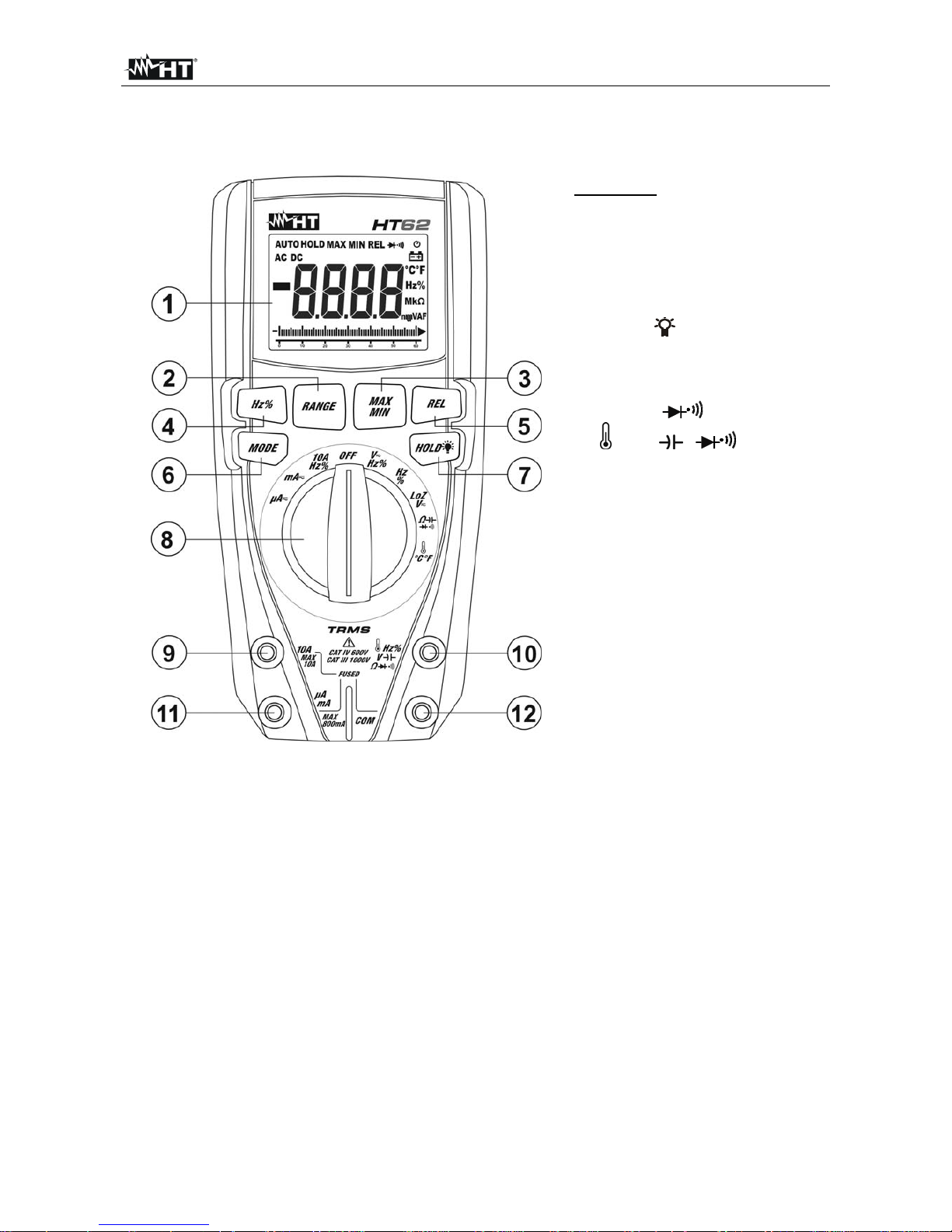
4.1. DESCRIPTION OF THE INSTRUMENT
CAPTION:
1. LCD display
2. RANGE key
3. MAXMIN key
4. Hz% key
5. REL key
6. MODE key
7. HOLD key
8. Rotary selector switch
9. Input terminal 10A
10. Input terminal
VHz% (HT61) or
Hz%V (HT62).
11. Input terminal mAA
12. Input terminal COM
Fig. 1: Description of the instrument
HT61 - HT62
EN - 7
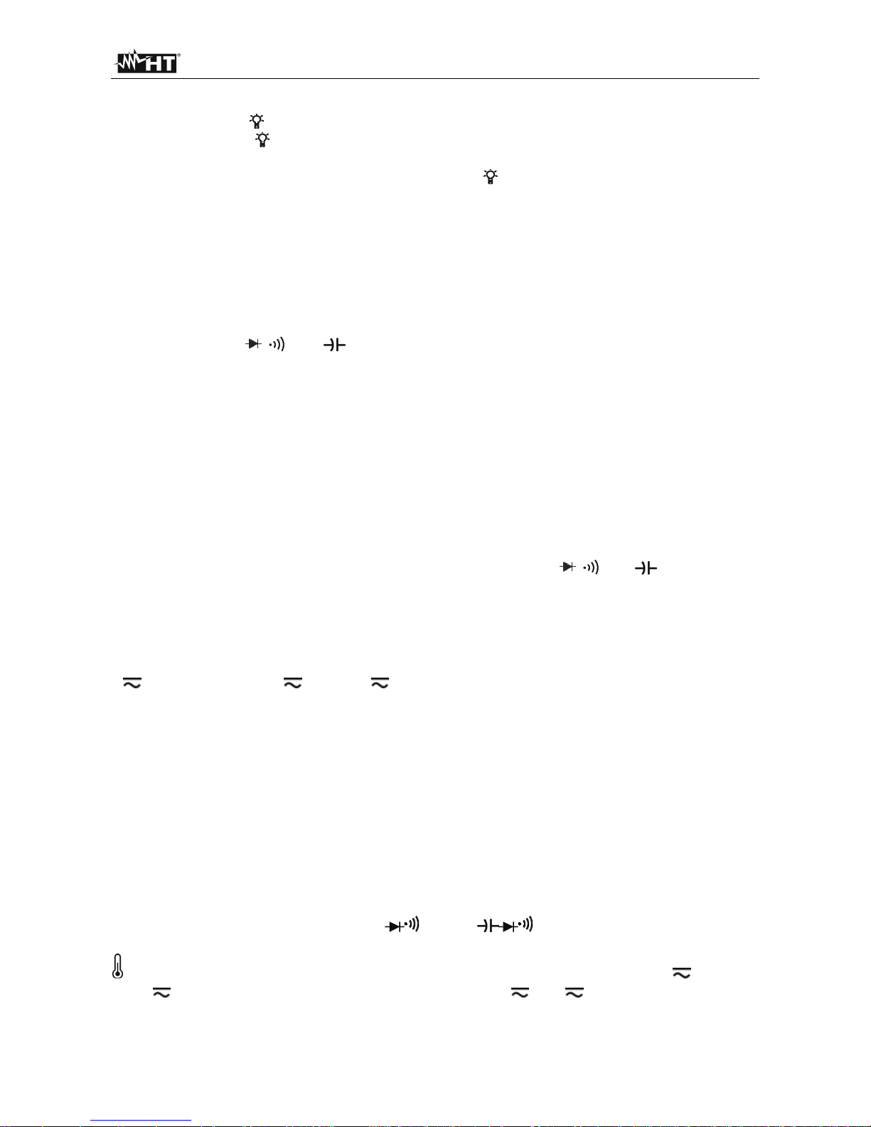
4.2. DESCRIPTION OF FUNCTION KEYS
4.2.1. HOLD key
Pressing the HOLD key freezes the value of the measured quantity on the display. After
pressing this key, the message “HOLD” appears on the display. Press the HOLD key again
to exit the function. Press and hold the HOLD key for a long time in order to
activate/deactivate the display’s backlight. This function is activated in any position of the
rotary switch and is automatically deactivated after approx. 10s.
4.2.2. RANGE key
Press the RANGE key to activate the manual mode and to disable the Autorange function.
The symbol “AUTO” disappears from the upper left part of the display. In manual mode,
press the RANGE key to change measuring range: the relevant decimal point will change
its position. The RANGE key is not active in Frequency measurement and Duty cycle test
and in positions
and (HT62) of the rotary switch. In Autorange mode, the
instrument selects the most appropriate ratio for carrying out measurement. If a reading is
higher than the maximum measurable value, the indication
“O.L” appears on the display.
Press and hold the RANGE key for more than 1 second to exit the manual mode.
4.2.3. MAX MIN key
Pressing the MAX MIN key once activates the detection of maximum and minimum values
of the quantity being tested. Both values are constantly updated and are displayed
cyclically every time the same key is pressed again. The display shows the symbol
associated with the selected function: “MAX” for maximum value and “MIN” for minimum
value. The MAX MIN key is not active when the HOLD function is activated. Pressing the
MAX MIN key the “AUTO” and bargraph disappears. The MAX MIN key is not active in
Frequency measurement and Duty cycle test and in positions and (HT62) of the
rotary switch. Press and hold the MAX MIN key for more than 1 second or turn the selector
to exit the function.
4.2.4. Hz% key
Press the Hz% key to select frequency measurement and duty cycle test in positions
V Hz %, 10AHz%, mA (AC), A (AC) and Hz% of the rotary switch. The frequency
range is different in the different positions.
4.2.5. REL key
Press the REL key to activate relative measurement. The instrument zeroes the display
and saves the displayed value as a reference value which subsequent measurements will
be referred to. The symbol “REL” appears on the display. This function is not active for the
following measurements: Hz, Duty Cycle, Continuity Test, Diode test and Temperature
(HT62). Pressing the REL key the “AUTO” and bargraph disappears Press the key again
to exit the function.
4.2.6. MODE key
Pressing the MODE key allows selecting a double function on the rotary switch. In
particular, it is active in position and (HT62) to select diode test,
continuity test, capacitance measurement (HT62) and resistance measurement, in position
°C°F (HT62) to select temperature measurement in °C or °F, in positions V Hz% and
LoZV for AC or DC voltage selection and mA , A to select AC or DC
measurements
 Loading...